Egress scheduling
On 7730 SXR platforms, the traffic management unit (TMU) uses egress schedulers to manage the distribution of scheduling resources available to process egress traffic. Two configurable egress scheduling policies are supported:
- Queue scheduling policy (at subinterface [CVLAN] and interface-queue level)
- Scheduling class scheduling policy (at interface level)
The following diagram shows the flow of traffic from queues through example queue schedulers and scheduling class schedulers.
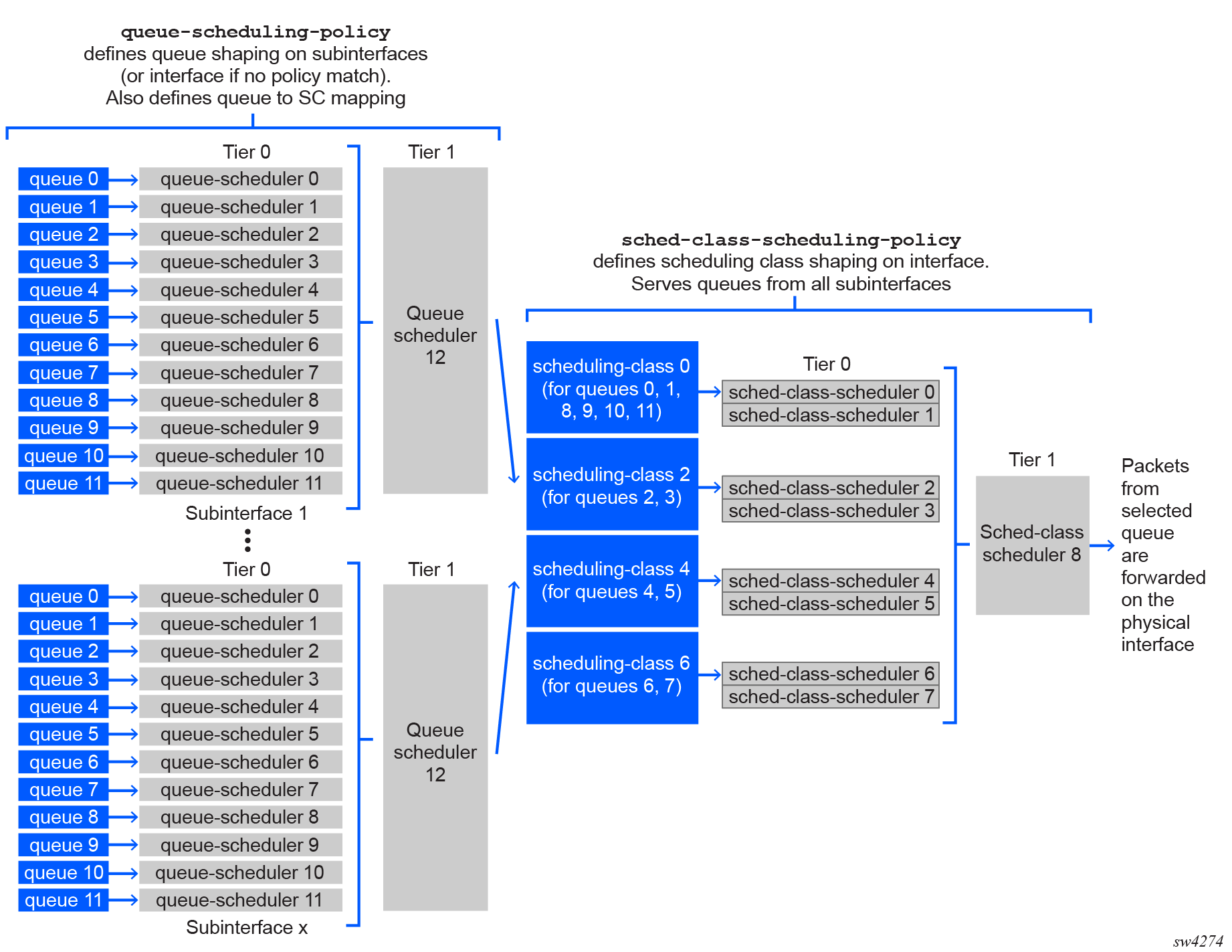
Queue scheduling policy (at subinterface [CVLAN] and interface-queue level)
Queue scheduling policies manage the distribution of scheduling resources available to process traffic in egress queues. The following figure illustrates the default queue scheduling policy.
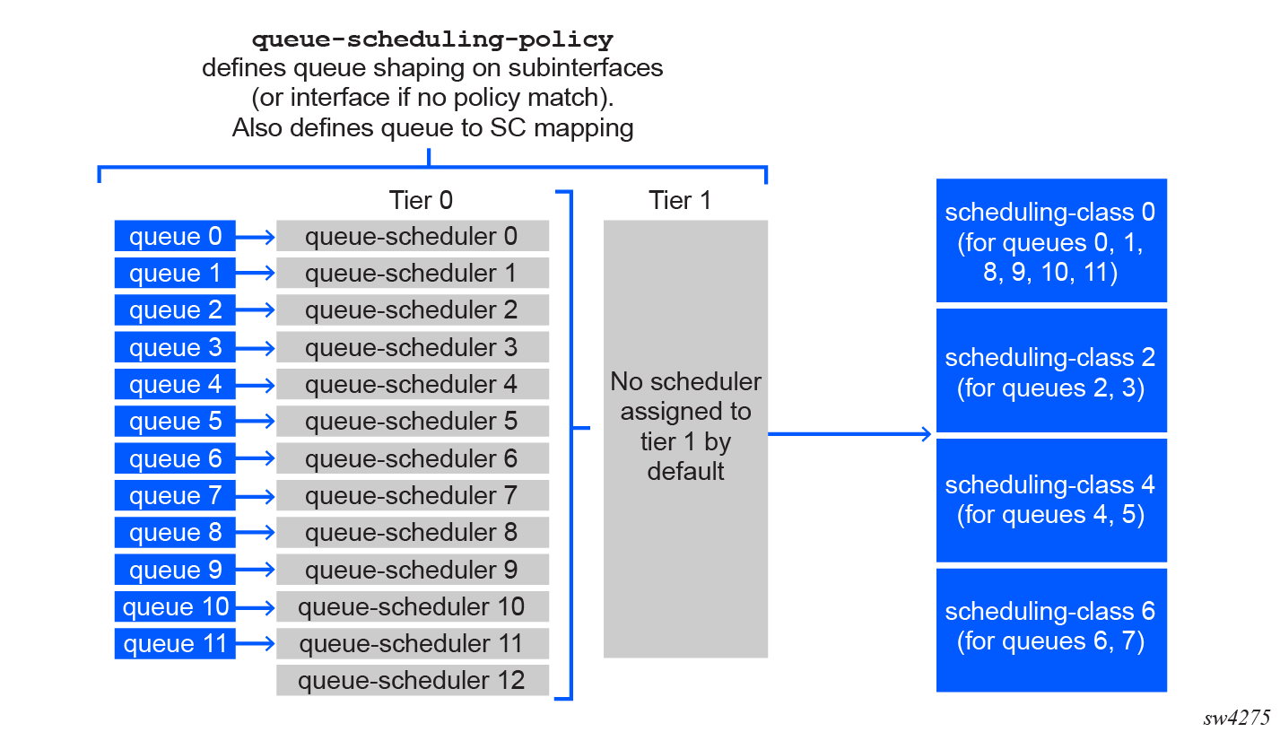
The queue scheduling policies define the following hierarchy of scheduling tiers:
- Tier 0: Up to 12 schedulers, each of which can provide shaping for single or multiple queues. The egress queues are processed initially by tier 0 schedulers, which in turn feed into the tier 1 scheduler.
- Tier 1: One scheduler, which provides aggregate-level shaping for all queues.
A total of 13 tier 0 and tier 1 schedulers can be defined. Within a queue scheduling policy, each defined queue must be mapped as an input to one of the tier 0 schedulers. The tier 0 schedulers are in turn mapped as inputs to the tier 1 scheduler. For each queue scheduler, shaper bucket thresholds determine how the scheduling resources are distributed by the scheduler.
The queue scheduling policies are applied at subinterface-level (such as CVLANs) to manage the defined subinterface queues. They are also applied at interface-level for any traffic that does not match any policies defined for subinterfaces.
The queue scheduling policies also support the mapping of each of the 12 egress queues to one of four scheduling classes: 0, 2, 4, and 6. If multiple queues are assigned to the same tier 0 scheduler, they must also be assigned to the same scheduling class.
The queues within a tier 0 scheduler draw bandwidth proportional to their weights. The tier 0 scheduler draws bandwidth based on the scheduling class. The tier 0 schedulers with higher scheduling classes are scheduled ahead of the lower scheduling classes and are capped by their rate. The scheduler rate can be defined as an absolute value (from 64Kb/s to 400Gb/s), or as a percentage value of the line rate.
The interface-level scheduling class schedulers provide further shaping.
Scheduling class scheduling policy (at interface level)
Scheduling class scheduling policies manage the distribution of scheduling resources available to process traffic in scheduling classes. The following figure illustrates the default scheduling class scheduling policy.
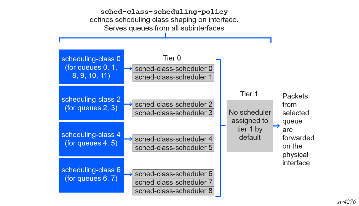
Similar to queue scheduling policies, the scheduling class scheduling policies define the following hierarchy of scheduling tiers:
- Tier 0: Up to 8 schedulers, each of which can provide shaping for single or multiple scheduling classes exiting the queue schedulers. The scheduling classes are processed initially by tier 0 schedulers, which in turn feed into the tier 1 scheduler.
- Tier 1: One scheduler, which provides aggregate-level shaping for all scheduling classes.
A total of 9 tier 0 and tier 1 schedulers can be defined. Also similar to queue schedulers, shaper bucket thresholds determine how the scheduling resources are distributed by the scheduler within each scheduling class scheduler.
The scheduling class scheduling policies are applied at interface level.
Queue and scheduling class policies applied to interface and subinterface
The following diagram shows the flow of packet processing through the queue and scheduling class scheduler policies applied to a subinterface and to an interface.
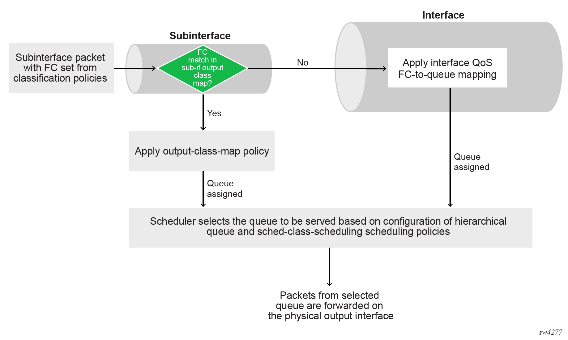
When a packet arrives on a subinterface for queueing at egress, the system performs the following steps.
-
Compare the packet FC (derived from one of the ingress classification policies) against the subinterface queue policies.
- If a match is found, assign a queue for the packet based on the output class map policy.
- If no match is found, assign the packet to a queue based on the interface-level FC-to-queue mapping.
-
The queues are scheduled based on the configured queue and scheduling class policies. The tier-1 scheduler allocates available bandwidth to its children serving the higher scheduling classes first and allocating the remaining bandwidth until none remains. And within a scheduling class, the available bandwidth is allocated to children in a weighted fair manner.
Queue scheduling policy example
The queue scheduling hierarchy consists of queues feeding multiple tier 0 schedulers which in turn feed into a single tier 1 scheduler that aggregates all queues from tier 0.
The following example shows the queue scheduling policy configuration for three queues, where scheduler 4 in tier 1 is configured with the inputs auto-input parameter, which indicates that all tier 0 schedulers are inputs to scheduler 4. (The auto-input option cannot be set for a tier 0 scheduler.)
--{ candidate shared default }--[  ]--
# info qos scheduler-policies queue-scheduling-policy test-sub-interface
    qos {
        scheduler-policies {
            queue-scheduling-policy test-sub-interface {
                queue af1-queue {
                    scheduling {
                        scheduling-class 4
                        weight 2
                        packet-length-adjustment {
                            add 0
                        }
                    }
                }
                queue af2-queue {
                    scheduling {
                        scheduling-class 4
                        weight 4
                        packet-length-adjustment {
                            add 0
                        }
                    }
                }
                queue be-queue {
                    scheduling {
                        scheduling-class 0
                        packet-length-adjustment {
                            add 0
                        }
                    }
                }
                queue ef-queue {
                    scheduling {
                        scheduling-class 6
                        packet-length-adjustment {
                            add 0
                        }
                    }
                }
                scheduler 0 {
                    tier 0
                    rate {
                        peak-rate-percentage 100
                    }
                    inputs {
                        queue [
                            be-queue
                        ]
                    }
                }
                scheduler 1 {
                    tier 0
                    rate {
                        peak-rate-percentage 80
                    }
                    inputs {
                        queue [
                            af1-queue
                            af2-queue
                        ]
                    }
                }
                scheduler 2 {
                    tier 0
                    rate {
                        peak-rate-percentage 20
                    }
                    inputs {
                        queue [
                            expedite-queue
                        ]
                    }
                }
                scheduler 4 {
                    tier 1
                    rate {
                        peak-rate-kbps 7000
                    }
                    inputs {
                        inputs auto-input
                    }
                }
            }
        }
    }
Scheduling class scheduling policy example
At interface-level, the scheduling hierarchy consists of scheduling classes feeding multiple tier 0 schedulers which in turn feed into a single tier 1 scheduler that aggregates all scheduling-classes from tier 0.
The following example shows the scheduling class scheduling policy configuration for three scheduling classes.
Similar to the queue policy, the tier 1 scheduler 2 is configured with the inputs auto-input parameter, which indicates that all tier 0 schedulers are inputs to this scheduler. (If the auto-input option is set for a tier 0 scheduler, all defined queues are inputs to this scheduler. In that case, none of other tier 0 schedulers can have queues defined as explicit inputs.)
--{ candidate shared default }--[  ]--
# info qos scheduler-policies sched-class-scheduling-policy sched-class-scheduling-policy-name
    qos {
        scheduler-policies {
            sched-class-scheduling-policy sched-class-scheduling-policy-name {
                scheduler 1 {
                    tier 0
                    rate {
                        peak-rate-kbps 10000
                        pir-adaptation-rule closest
                    }
                    inputs {
                        scheduling-class [
                            0
                            4
                        ]
                    }
                }
                scheduler 2 {
                    tier 1
                    rate {
                        peak-rate-kbps 10000
                        pir-adaptation-rule closest
                    }
                    inputs {
                        inputs auto-input
                    }
                }
                scheduler 3 {
                    tier 0
                    rate {
                        peak-rate-kbps 2000
                        pir-adaptation-rule closest
                    }
                    inputs {
                        scheduling-class [
                            6
                        ]
                    }
                }
            }
        }
    }
Default scheduling policy settings
Default interface queues
The following table shows the default settings applied to the interface-level queues. At interface level, all 12 queues are created by default. The table lists default settings for all queues, including the scheduling-related parameters.
| default-queue-name | queue-index | committed-burst-size | maximum-burst-size | peak-rate-percent | weight | scheduling-class |
|---|---|---|---|---|---|---|
| queue-0 | 0 | default | max | 100 | 1 | 0 |
| queue-1 | 1 | default | max | 100 | 1 | 0 |
| queue-2 | 2 | default | max | 100 | 1 | 2 |
| queue-3 | 3 | default | max | 100 | 1 | 2 |
| queue-4 | 4 | default | max | 100 | 1 | 4 |
| queue-5 | 5 | default | max | 100 | 1 | 4 |
| queue-6 | 6 | default | max | 100 | 1 | 6 |
| queue-7 | 7 | default | max | 100 | 1 | 6 |
| queue-8 | 8 | default | max | 100 | 1 | 0 |
| queue-9 | 9 | default | max | 100 | 1 | 0 |
| queue-10 | 10 | default | max | 100 | 1 | 0 |
| queue-11 | 11 | default | max | 100 | 1 | 0 |
To change the queue scheduling parameters, assign a custom queue scheduling policy to the interface. Similarly, to modify default scheduling behavior between scheduling classes at the interface level, assign a custom scheduling class scheduling policy to an interface.
Default subinterface queues
At subinterface level, local queues are created only after an output class map is assigned to the subinterface. By default, the queue parameters are set as described in the interface table above, using the queue-index as a key. To change queue scheduling parameters, assign a custom queue scheduling policy to the subinterface.
Default scheduling threshold policies
By default, the system provides the following two non-configurable scheduling threshold policies:
- per-scheduling-class
- single
The following diagram shows the default scheduling threshold policies. Both tier 0 schedulers are assigned the default scheduling-threshold-policy single, while both tier 1 schedulers are assigned the default scheduling-threshold-policy per-scheduling-class.

Custom-defined scheduling threshold policies are not supported.
Scheduling threshold policy: per-scheduling-class
The per-scheduling-class policy ensures that each scheduling class is assigned a distinct priority level within a shaper bucket.
The shaping of scheduling classes occurs in relation to the shaper token level. This process can be illustrated by considering scheduling class 3, which is associated with threshold level 3. If the token level is below threshold level 3, but above threshold level 2, queues associated with scheduling class 3 are shaped to enforce the overall rate of the bucket. Queues associated with scheduling class 3 are not shaped by this bucket if the shaper token level is at or above threhold level 3, or if the token level drops below threshold level 2.
The per-scheduling-class policy is assigned to tier 1 schedulers by default, both in the queue scheduling policies and the scheduling class scheduling policies. These settings are non-configurable.
The default per-scheduling-class policy is as follows:
qos {
   scheduling-policies {
      scheduling-threshold-policy "per-scheduling-class" {
         threshold 0 {
            maximum-scheduling-class 0
         }
         threshold 2 {
            maximum-scheduling-class 2
         }
         threshold 4 {
            maximum-scheduling-class 4
         }
         threshold 6 {
            maximum-scheduling-class 6
         }
      }
   }
}
Scheduling threshold policy: single
The single scheduling threshold policy places all scheduling classes on the first threshold level, avoiding multiple priority levels and the corresponding increases in burst tolerance.
The single policy is assigned to tier 0 schedulers by default, in both the queue scheduling policy and scheduling class scheduling policy. This setting is non-configurable.
qos {
   scheduling-policies {
      scheduling-threshold-policy "single" {
         threshold 0 {
            maximum-scheduling-class 6
         }
      }
   }
}
Modifying threshold level bucket depths
The size of the shaper buckets for all threshold levels used in the default scheduling threshold policies are defined in relation to the burst-allowance and threshold-separation parameters. These parameters are defined for queues and scheduling classes using queue scheduling policies and scheduling class scheduler policies.
Configuring queue scheduling policies
To configure queue scheduling policies, use the qos scheduler-policies queue-scheduling-policy command.
Configure a tier 0 queue scheduling policy
The following example shows a custom configuration for one queue and one scheduler in a tier 0 queue scheduling policy. The queue is assigned a scheduling class and weight, while the scheduler is assigned tier, burst, threshold-separation, and rate parameters and associated queues.
--{ * candidate shared default }--[  ]--
# info qos scheduler-policies queue-scheduling-policy custom-tier-0-queue-policy
    qos {
        scheduler-policies {
            queue-scheduling-policy custom-tier-0-queue-policy {
                queue queue-01 {
                    scheduling {
                        scheduling-class 0
                        weight 10
                    }
                }
                scheduler 0 {
                    tier 0
                    burst-allowance 10000
                    threshold-separation 28672
                    rate {
                        peak-rate-percentage 80
                    }
                    inputs {
                        queue [
                            queue-01
                        ]
                    }
                }
            }
        }
    }
Configure a tier 1 queue scheduling policy
The following example shows a custom configuration for all queues in a tier 1 queue scheduling policy. The scheduler is assigned a tier, burst, threshold-separation, and rate parameters. All queues egressing the tier 0 schedulers feed into this single tier 1 scheduler using the inputs auto-input option.
--{ candidate shared default }--[  ]--
# info qos scheduler-policies queue-scheduling-policy custom-tier-1-queue-policy
    qos {
        scheduler-policies {
            queue-scheduling-policy custom-tier-1-scheduling-policy {
                scheduler 14 {
                    tier 1
                    burst-allowance 11000
                    threshold-separation 28672
                    rate {
                        peak-rate-percentage 100
                    }
                    inputs {
                        inputs auto-input
                    }
                }
            }
        }
    }
Applying queue scheduling policies to subinterfaces
To apply queue scheduling policies to egress traffic on a subinterface, specify the required policy using the qos interfaces interface output scheduler command.
Apply queue scheduling policies to a subinterface
The following example shows a tier 0 queue scheduling policy applied to a subinterface.
--{ * candidate shared default }--[  ]--
# info qos interfaces
    qos {
        interfaces {
            interface eth-1/1.1 {
                interface-ref {
                    interface ethernet-1/1
                    subinterface 1
                }
                output {
                    scheduler {
                        queue-scheduling-policy custom-tier-0-queue-policy
                    }
                }
            }
        }
    }
Configuring scheduling class scheduling policies
To configure scheduling class scheduling policies, use the qos scheduler-policies sched-class-scheduling-policy <name> command.
Configure a tier 0 scheduling class scheduling policy
The following example shows a custom configuration for one scheduler included in a tier 0 scheduling class scheduling policy. The scheduler is assigned tier, burst, threshold-separation, and rate parameters, and associated scheduling classes.
--{ * candidate shared default }--[  ]--
# info qos scheduler-policies sched-class-scheduling-policy custom-tier-0-sched-class-policy
    qos {
        scheduler-policies {
            sched-class-scheduling-policy custom-tier-0-sched-class-policy {
                scheduler 0 {
                    tier 0
                    burst-allowance 10000
                    threshold-separation 28672
                    rate {
                        peak-rate-percentage 90
                    }
                    inputs {
                        scheduling-class [
                            0
                            2
                        ]
                    }
                }
            }
        }
    }
Configure a tier 1 scheduling class scheduling policy
The following example shows a custom configuration for a tier 1 scheduling class scheduling policy. The scheduler is assigned tier, burst, threshold-separation, and rate parameters. All scheduling classes egressing the tier 0 schedulers feed into this single tier 1 scheduler using the inputs auto-input option.
--{ candidate shared default }--[  ]--
# info qos scheduler-policies queue-scheduling-policy custom-tier-1-queue-policy
    qos {
        scheduler-policies {
            queue-scheduling-policy custom-tier-1-scheduling-policy {
                scheduler 14 {
                    tier 1
                    burst-allowance 11000
                    threshold-separation 28672
                    rate {
                        peak-rate-percentage 100
                    }
                    inputs {
                        inputs auto-input
                    }
                }
            }
        }
    }
Applying scheduling class scheduling policies to interfaces
To apply scheduling class scheduling policies to egress traffic on an interface, specify the required policy using the qos interfaces interface output scheduler command.
Apply scheduling class scheduling policies to an interface
The following example shows a tier 0 scheduling class scheduling policy applied to a an interface.
--{ * candidate shared default }--[  ]--
# info qos interfaces
    qos {
        interfaces {
            interface eth-1/1 {
                interface-ref {
                    interface ethernet-1/1
                }
                output {
                    scheduler {
                        sched-class-scheduling-policy custom-tier-0-sched-class-policy
                    }
                }
            }
        }
    }
Scheduling priority mapping table
The scheduling priority mapping table is a global table that maps individual scheduling classes into three scheduling priorities at the hardware level. Scheduling priority 0 is the lowest priority, and priority 2 is the highest.
The following table shows the default settings:
| Scheduling class | Scheduling priority |
|---|---|
| 0 | 0 |
| 2 | 0 |
| 4 | 1 |
| 6 | 2 |
Configuring the scheduling priority mapping table
To configure the scheduling priority mapping table, use the qos scheduler-policies scheduling-priority-mapping-table command.
Configure scheduling priority mapping table
--{ * candidate shared default }--[  ]--
# info qos scheduler-policies scheduling-priority-mapping-table
    qos {
        scheduler-policies {
            scheduling-priority-mapping-table {
                scheduling-class 0 {
                    scheduling-priority 0
                }
                scheduling-class 2 {
                    scheduling-priority 0
                }
                scheduling-class 4 {
                    scheduling-priority 1
                }
                scheduling-class 6 {
                    scheduling-priority 2
                }
            }
        }
    }
Egress queue scheduling resource management
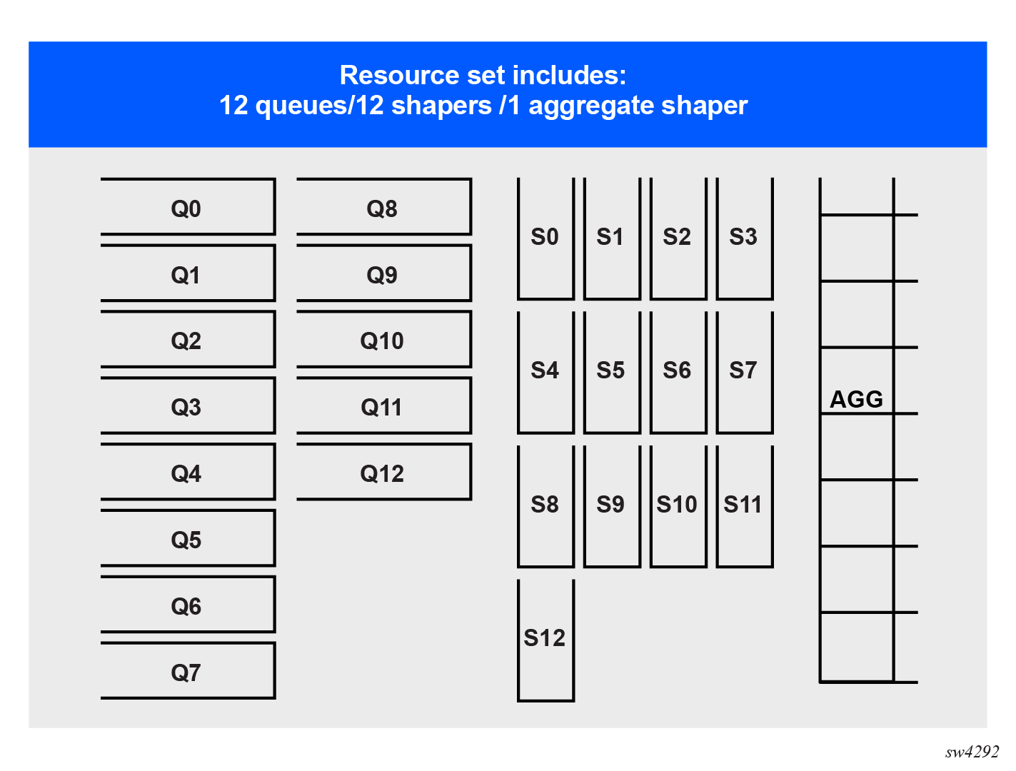
The resource management of output queues, tier 0 queue schedulers, and tier 1 queue schedulers is based on resource sets consisting of:
- 12 output queues
- 12 tier 0 queue schedulers
- one tier 1 queue scheduler
Every subinterface that is created is allocated a resource set regardless of the number of local queues configured in its associated output class map and regardless of the number of schedulers configured in its associated queue scheduling policy. This is to prevent changes in any of the scheduling policies from causing depletion of resources for the subinterface.
The following diagram shows a resource set consisting of queues, tier 0 schedulers, and a single tier 1 scheduler.
At the highest level, all resource sets are collected into two resource set pools. Each resource set pool contains 62 resource groups. And each resource groups contains 256 resource sets.
These resource groups are allocated to interface group resource pools, defining the interface-level resource sets that subinterfaces require to process queues.
At interface level, every interface is statically mapped to an interface group resource pool. The resource groups are dynamically allocated to the interface group resource pool based on demand. On an interface, all subinterfaces associated with the given interface group resource pool share the available resource sets.
The following figure shows the organization of resource sets to interfaces and subinterfaces.
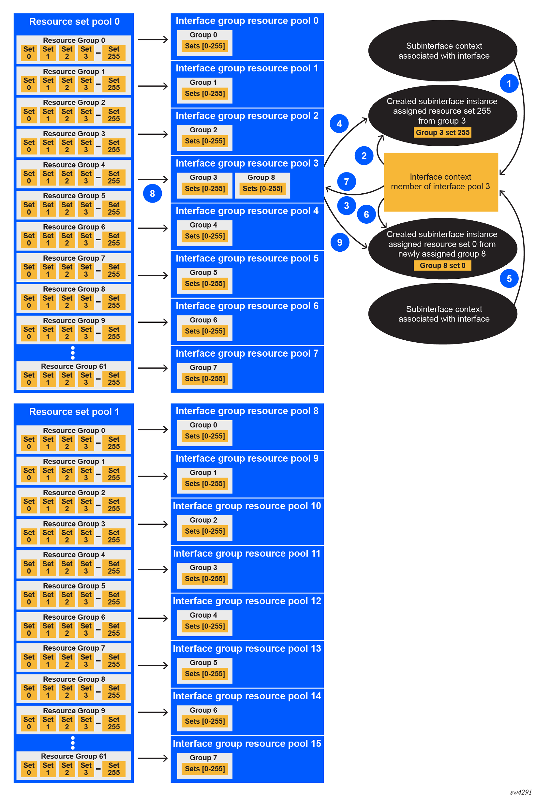
At system initialization, every interface group resource pool is allocated a single resource group from the corresponding resource set pool.
As the individual subinterfaces are created, the resource sets are allocated from the corresponding resource group. If a new subinterface is created and all resource sets in a group are already allocated, a new resource group is allocated to the interface group resource pool. This allocation is persistent, such that when a resource group is allocated to an interface group resource pool, it remains allocated even if all corresponding resource sets become free.
If subinterface queues are mapped to interface queues as a result of exhaustion of available resources, the output-class-map-pending flag indicates the interfaces that failed to allocate the queue resources. To view this flag, use the info from state qos interfaces interface output output-class-map-pending command.
In the system state information, a container is available under scheduling-resources-pools listing the scheduling resource pools individual interfaces are using resources from. This mapping is static, but it is platform dependent.
--{ candidate shared default }--[ ] --
# info from state qos interfaces interface eth1 output scheduler
    scheduling-resources-pools {
        resource-set-pool 1
        interface-group-resource-pool 12
    }
There is also a state table under qos resource-set-pool that tracks the utilization of the individual resource groups and their allocation to interface group resource pools.
--{ candidate shared default }--[ ] --
# info from state platform linecard 1 forwarding-complex 1 qos
    qos {
        ...
        resource-set-pool 0 {
        ...
        }
        resource-set-pool 1 {
           interface-group-resource-pool 8 {
               resource-group 0 {
                   resource-set-used 253
                   resource-set-free 3
               }
           }
           interface-group-resource-pool 9 {
               resource-group 1 {
                   resource-set-used 0
                   resource-set-free 256
               }
           }
            interface-group-resource-pool 10 {
               resource-group 2 {
                   resource-set-used 0
                   resource-set-free 256
               }
           }
           interface-group-resource-pool 11 {
               resource-group 3 {
                   resource-set-used 255
                   resource-set-free 1
               }
               resource-group 8 {
                   resource-set-used 1
                   resource-set-free 255
               }
           }
           ...
           interface-group-resource-pool 15 {
               resource-group 7 {
                   resource-set-used 255
                   resource-set-free 1
               }
           }
        }
    }
Each configured subinterface requires one resource set at minimum. However, if the subinterface is created on a LAG, one resource set per LAG member is allocated. Depending on the configuration, this can lead to depletion of the resources. In such a case, the subinterface points to interface-based queues (remote-output-queue) overriding any output class map configuration. If the resource set in the corresponding interface group resource pool becomes available, the system automatically assigns it to the subinterface waiting for such a resource set.