QoS resource management tables
On 7730 SXR platforms, resource management tables define how different internal resources are used in times of overload. The resource management tables are global, such that the same configuration applies to all forwarding complexes in the system.
The resource management tables govern the behavior of the following internal resources.
- Buffer segments
These are 512 byte buffer segments. As packets arrive, the first 384 bytes of the packet are sent to the thread processing the packet. The remaining portion of the packet is assigned to buffer segments in memory. If the packet is forwarded without queuing, the portion in the thread buffer does not consume a buffer segment. If the packet is queued, the thread portion is moved into memory, consuming a buffer segment. When the assigned buffer segments are sent to the transmit pipeline for forwarding, the buffer segments are freed.
- Packet IDs
Packet ID is the resource at each slice (400G or I/O) that tracks the ordering of in-flight packets. As packets are received, they are assigned a packet ID context in the receiving slice’s Re-Order-Engine (ROE). The packet is then handed off to a thread for processing. The packet ID is initially placed in the main ROE context for the slice. Early in processing, the thread makes a request to the ROE to move the packet’s ID from the main reordering queue to an ROE subcontext queue (one of 1024 per slice). The ROE context waits for the packet ID to reach the head of the main queue and then moves the packet ID to the specified subcontext queue. As the thread finishes processing the packet, it is either moved into a queue for future egress forwarding or sent directly to the target port's transmit pipeline. This only happens when the packet ID reaches the head of the subcontext’s queue. This mechanism keeps packets in order based on the subcontext, preventing out-of-order forwarding.
A limited number of packet IDs exist and the slice’s ROE can exhaust its free list of packet IDs in the rare case where packets are arriving faster than being released. Longer processing times in the thread are a primary cause of packet ID exhaustion. To mitigate this issue, the ROE subcontexts are grouped based on expected processing time. This minimizes head-of-line blocking within the subcontexts.
- Header buffers
Each thread has two header buffers used to process packets. When the system first comes up, each thread advertises one of the header buffers to an I/O slice and waits for a packet to be assigned by the slice’s scatter block. Just before processing is finished for the first packet, the other header buffer is advertised to allow another packet to be assigned to the thread to allow the thread to minimize the amount of time the thread is idle between packets. While the thread is processing the new packet, the system works in the background to flush the older header buffer. When the older header buffer is flushed and the thread has neared the end of processing the newer packet, the old header buffer is advertised as available. The alternate advertising of the thread’s header buffers continues in this fashion.
The following three tables control the logic related to resource management on 7730 SXR platforms:
- Forwarding class resource priority table
- Resource utilization zones table
- Drop zone table
Forwarding class resource priority table
The forwarding class resource priority table maps forwarding class and profile combinations for unicast and multicast traffic into one of four priorities (0 to 3); where 0 corresponds to the lowest priority and 3 is the highest.
The following shows the default settings for the forwarding class resource priority table:
| Default FC name | FC index | Priority | in-plus | in | out | exceed | in-low | out-low |
|---|---|---|---|---|---|---|---|---|
| fc0 | 0 | unicast priority | 0 | 0 | 0 | 0 | 0 | 0 |
| multicast priority | 0 | 0 | 0 | 0 | 0 | 0 | ||
| fc1 | 1 | unicast priority | 0 | 0 | 0 | 0 | 0 | 0 |
| multicast priority | 0 | 0 | 0 | 0 | 0 | 0 | ||
| fc2 | 2 | unicast priority | 1 | 1 | 0 | 0 | 0 | 0 |
| multicast priority | 1 | 1 | 0 | 0 | 0 | 0 | ||
| fc3 | 3 | unicast priority | 1 | 1 | 0 | 0 | 0 | 0 |
| multicast priority | 1 | 1 | 0 | 0 | 0 | 0 | ||
| fc4 | 4 | unicast priority | 2 | 2 | 1 | 1 | 0 | 0 |
| multicast priority | 2 | 2 | 1 | 1 | 0 | 0 | ||
| fc5 | 5 | unicast priority | 2 | 2 | 1 | 1 | 0 | 0 |
| multicast priority | 2 | 2 | 1 | 1 | 0 | 0 | ||
| fc6 | 6 | unicast priority | 3 | 3 | 2 | 2 | 0 | 0 |
| multicast priority | 3 | 3 | 2 | 2 | 0 | 0 | ||
| fc7 | 7 | unicast priority | 3 | 3 | 2 | 2 | 0 | 0 |
| multicast priority | 3 | 3 | 2 | 2 | 0 | 0 | ||
| fc8 | 8 | unicast priority | 0 | 0 | 0 | 0 | 0 | 0 |
| multicast priority | 0 | 0 | 0 | 0 | 0 | 0 | ||
| fc9 | 9 | unicast priority | 0 | 0 | 0 | 0 | 0 | 0 |
| multicast priority | 0 | 0 | 0 | 0 | 0 | 0 | ||
| fc10 | 10 | unicast priority | 0 | 0 | 0 | 0 | 0 | 0 |
| multicast priority | 0 | 0 | 0 | 0 | 0 | 0 | ||
| fc11 | 11 | unicast priority | 0 | 0 | 0 | 0 | 0 | 0 |
| multicast priority | 0 | 0 | 0 | 0 | 0 | 0 | ||
| fc12 | 12 | unicast priority | 0 | 0 | 0 | 0 | 0 | 0 |
| multicast priority | 0 | 0 | 0 | 0 | 0 | 0 | ||
| fc13 | 13 | unicast priority | 0 | 0 | 0 | 0 | 0 | 0 |
| multicast priority | 0 | 0 | 0 | 0 | 0 | 0 | ||
| fc14 | 14 | unicast priority | 0 | 0 | 0 | 0 | 0 | 0 |
| multicast priority | 0 | 0 | 0 | 0 | 0 | 0 | ||
| fc15 | 15 | unicast priority | 0 | 0 | 0 | 0 | 0 | 0 |
| multicast priority | 0 | 0 | 0 | 0 | 0 | 0 |
Resource utilization thresholds table
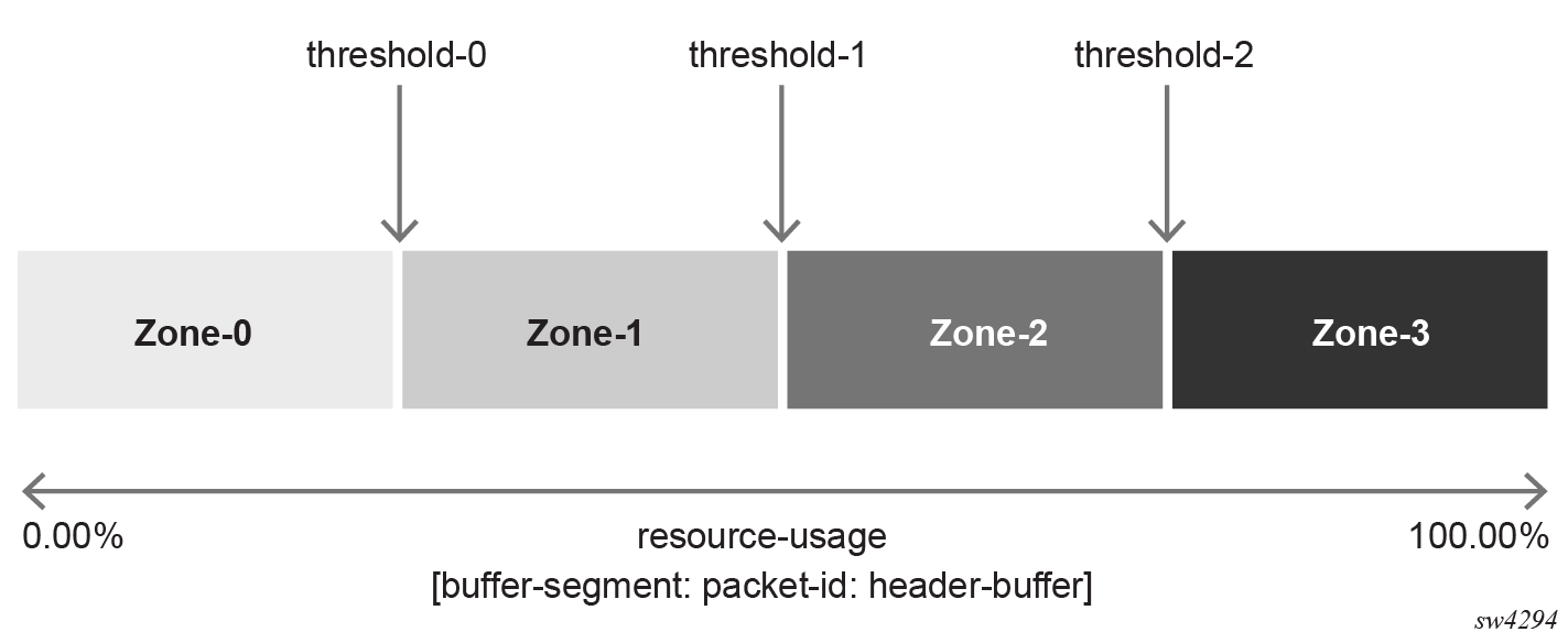
The utilization of the individual resources (buffer segments, packet IDs, and header buffers) are divided into zones defined by the utilization thresholds for each resource. As packets arrive, the current zone for each resource is sent to the thread processing the packet. When the thread determines the resource priority for the current packet, it identifies the configured zone where that resource priority can cause an early discard of the packet. If the drop-zone has been exceeded, the thread discards the packet and increments the resource discard counter. If the drop-zone has not been exceeded, processing continues. As utilization increases and decreases, the current zone for each resource changes accordingly.
Conceptually, every resource is divided into four zones by configuring three thresholds, as shown in the figure below. Zone 0 indicates no congestion and therefore no drop is experienced while the resource utilization is within this zone.

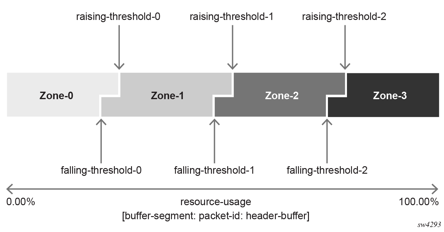
In practice, there are two thresholds defining each zone: the rising threshold and the falling threshold. Each threshold defines the boundaries between individual zones and are defined in term of percentage value (with granularity to 2 decimals) of the maximum resource value, as shown in the following figure.

The default values for the resource utilization zones table are defined as follows.
| threshold-0 | threshold-1 | threshold-2 | ||||
|---|---|---|---|---|---|---|
| rising | falling | rising | falling | rising | falling | |
| segment-buffer | 80 | 78 | 84 | 82 | 90 | 88 |
| packet-id | 80 | 78 | 84 | 82 | 90 | 88 |
| header-buffer | 88 | 86 | 92 | 90 | 96 | 94 |
Drop zone table
The drop zone table defines specific drop zones in which packets that correspond to a given resource priority are dropped. The drop zones are defined separately for unicast and multicast traffic. The resource priorities are defined by the mapping in the forwarding class resource priority table.
The default settings for the drop zone table are as follows.
| Drop zone | Unicast priority | Multicast priority | ||||||
|---|---|---|---|---|---|---|---|---|
| 0 | 1 | 2 | 3 | 0 | 1 | 2 | 3 | |
| buffer-segment-drop-zone | 1 | 2 | 2 | 3 | 2 | 2 | 3 | 3 |
| packet-id-drop-zone | 1 | 2 | 2 | 3 | 2 | 2 | 3 | 3 |
| header-buffer-drop-zone | 1 | 2 | 2 | 3 | 2 | 2 | 3 | 3 |
Configuring the forwarding class resource priority table
To configure the forwarding class resource priority table, use the qos resource-management forwarding-class-resource-priority command.
Configure the forwarding class resource priority table
The following example shows the configuration of priority values for unicast and multicast traffic for forwarding-class fc1 with profile out.
--{ + candidate shared default }--[  ]--
# info qos resource-management
    qos {
        resource-management {
            forwarding-class-resource-priority {
                forwarding-class fc1 {
                    profile out {
                        unicast-resource-priority 1
                        multicast-resource-priority 0
                    }
                }
            }
        }
    }
Configuring the resource utlization thresholds table
To configure the resource utlization thresholds table, use the qos resource-management resource-utilization-thresholds command.
Configure the resource utlization zones table
The following example configures custom threshold values for the buffer segment, packet ID, and header buffer resources.
--{ + candidate shared default }--[  ]--
# info qos resource-management resource-utilization-thresholds threshold 1
    qos {
        resource-management {
            resource-utilization-thresholds {
                threshold 1 {
                    buffer-segment {
                        rising-threshold-value 88.00
                        falling-threshold-value 83.00
                    }
                    packet-id {
                        rising-threshold-value 88.00
                        falling-threshold-value 83.00
                    }
                    header-buffer {
                        rising-threshold-value 88.00
                        falling-threshold-value 83.00
                    }
                }
            }
        }
    }
Configuring the drop zone table
To configure the drop zone table, use the qos resource-management drop-zones command.
Configure the drop zone table
--{ + candidate shared default }--[  ]--
# info qos resource-management drop-zones
    qos {
        resource-management {
            drop-zones {
                unicast-priority 1 {
                    buffer-segment-drop-zone 1
                    packet-id-drop-zone 1
                    header-buffer-drop-zone 1
                }
                multicast-priority 1 {
                    buffer-segment-drop-zone 1
                    packet-id-drop-zone 1
                    header-buffer-drop-zone 1
                }
            }
        }
    }