Mirroring
Mirroring copies IPv4 and IPv6 packets seen on a specified source, such as an interface (port) or subinterface (VLAN), or matching an ACL entry, and sends the packets to a specific destination, such as a locally attached traffic analyzer or a tunnel toward a remote destination.
By default, the mirrored packets include IPv4/IPv6 headers, as well as Ethernet headers. Traffic from multiple sources can be mirrored to a single destination, although traffic from a specific source cannot be mirrored to multiple destinations.
Mirror sources
The source for mirrored traffic can be an interface or subinterface or an ACL filter.
-
Interfaces / subinterfaces
A mirror source can be an interface, including all subinterfaces within that interface. The source can be a single interface (for example,
interface
                        ethernet-1/1
) or a LAG (for example,interface lag1). Either a LAG member or LAG port can be mirrored. When a LAG port is configured as a mirror source, mirroring is enabled on all ports making up the LAG.The source can be a specific VLAN; that is, a subinterface within an interface where VLAN tagging is enabled (for example,
interface ethernet-1/1.1orlag1.1).You can configure mirroring for traffic in a specific direction (ingress only, egress only) or bidirectional traffic (both ingress and egress).
It is possible for the mirror source operational state to be down due to resource exhaustion. If the mirror source is not mirroring packets, check the operational state of the mirror sources .
-
ACL filters
A mirror source can be an IPv4 or IPv6 ACL filter, applied under one or more interfaces or subinterfaces. Traffic matching entries in the ingress ACL filter (regardless of whether the action is accept or drop), can be mirrored to the destination.
The following table lists hardware platform support for each mirror source.
| Source | 7220 IXR-D2/D3 | 7220 IXR-D2L/D3L | 7220 IXR-D4/D5 | 7250 IXR-6e/10e |
|---|---|---|---|---|
| Interface (ingress) | Yes | Yes | Yes | Yes |
| Interface (egress) | Yes | Yes | Yes | Yes |
| Subinterface (ingress) | Yes | Yes | Yes | Yes |
| Subinterface (egress) | Yes | Yes | No | Yes |
| ACL filter (ingress) | Yes | Yes | Yes | Yes |
| ACL filter (egress) | No | No | No | No |
Mirror destinations
Traffic from the mirror source can be copied to a local destination (local mirroring) or encapsulated into a tunnel to a remote destination (remote mirroring).
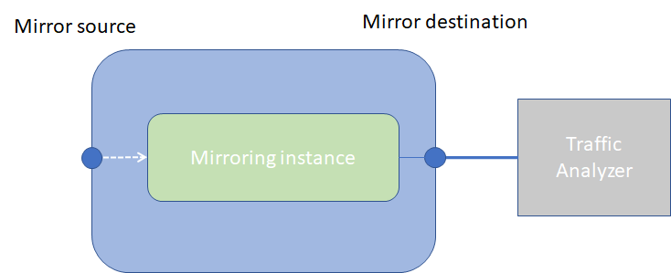
Local mirroring
In a local mirroring configuration, both the mirror source and mirror destination reside on the same SR Linux node, as shown in Local mirroring.
In this configuration, the local destination is a Switched Port Analyzer (SPAN).
For local mirroring, the following hardware types are supported:
-
7220 IXR-D2/D2L/D3/D3L
-
7220 IXR-D4/D5
-
7250 IXR-6e/10e
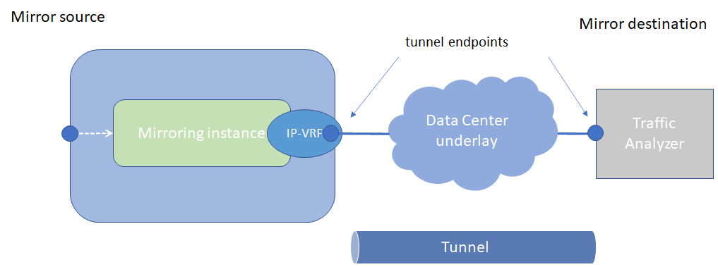
Remote mirroring
In a remote mirroring configuration, the mirror source and mirror destination are on different nodes. The mirror source resides on the SR Linux node, and the mirrored packets are encapsulated into a tunnel toward the mirror destination.
Remote mirroring shows a remote mirroring configuration. In this configuration, the remote destination is an Encapsulated Remote Switched Port Analyzer (ERSPAN).
Tunnel endpoints are defined within a specific network-instance, where the local tunnel endpoint IP address can be either a loopback subinterface address or any subinterface address within that network-instance.
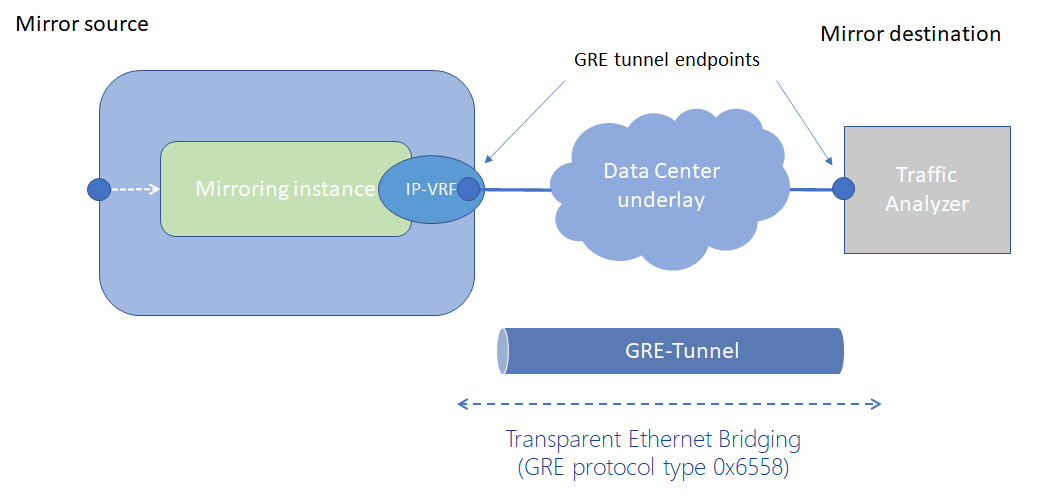
Mirroring to underlay (ERSPAN+GRE)
In a mirroring-to-underlay (ERSPAN+GRE) configuration, the mirrored packets, including IPv4/IPv6 header as well as Ethernet header, are tunneled using Transparent Ethernet Bridging (GRE protocol type 0x6558) or L3oGRE (protocol type 0x88be for 7250 IXR-6e/10e platforms only) toward the remote destination.
Mirroring to underlay shows a mirroring-to-underlay configuration.
For remote mirroring, the following hardware types are supported.
| Destination | 7220 IXR-D2/D3 | 7220 IXR-D2L/D3L | 7220 IXR-D4/D5 | 7250 IXR-6e/10e |
|---|---|---|---|---|
| Underlay destination (GRE+ERSPAN) - IPv4 (ingress and egress | Yes | Yes | Yes | Yes |
| Underlay destination (GRE+ERSPAN) - IPv6 (ingress-direction mirroring) | Yes | Yes | Yes | Yes |
| Underlay destination (GRE+ERSPAN) - IPv6 (egress-direction mirroring) | No | No | Yes | Yes |
Configuring mirroring
To configure mirroring, you configure a mirroring-instance, which specifies the source and destination for the mirrored traffic. Multiple mirror sources can have a single destination, although traffic from a specific source cannot be mirrored to multiple destinations. Only one mirror destination can be configured per mirroring-instance. A mirror destination cannot be reused in multiple mirroring instances.
Within a mirroring-instance, if an interface is configured as mirror source, a subinterface within that interface cannot be added as another mirror source. If a LAG is defined as mirror destination, only the first 8 members of the LAG carry mirrored traffic. Note that on 7220 IXR-D4 and D5 platforms, a mirror destination port cannot be a LAG.
Mirrored traffic is considered Best Effort (BE) Forwarding Class.
Configuring mirroring sources
To configure mirroring, you specify the source and destination for mirrored traffic within a mirroring-instance. The source in a mirroring-instance can be traffic on a specified interface, subinterface, or LAG, or can be packets matching an ACL entry.
interface source
The following example shows a mirroring-instance configuration with an interface as the source for mirrored traffic:
--{ * candidate shared default }--[ ]--
# info system mirroring
system {
mirroring {
mirroring-instance 1 {
admin-state enable
mirror-source {
interface ethernet-1/5 {
direction ingress-egress
}
}
}
}
}
ACL source
The following example configures an ACL with an entry that matches TCP packets and applies the ACL to a subinterface. A mirroring-instance is configured that uses packets matching the ACL as the source for mirrored traffic.
--{ * candidate shared default }--[ ]--
# info acl acl-filter ip_tcp type ipv4
acl {
acl-filter ip_tcp type ipv4 {
entry 1000 {
description Match_TCP_Protocol
match {
ipv4 {
protocol tcp
}
}
action {
accept {
}
}
}
}
}
--{ +* candidate shared default }--[ ]--
# info acl interface ethernet-1/1.1
acl {
interface ethernet-1/1.1 {
interface-ref {
interface ethernet-1/1
subinterface 1
}
input {
acl-filter ip_tcp type ipv4 {
}
}
}
}--{ * candidate shared default }--[ ]--
# info system mirroring
system {
mirroring {
mirroring-instance 1 {
admin-state enable
mirror-source {
acl {
acl-filter ip_tcp type ipv4 {
entry 1000 {
}
}
}
}
}
}
}
Configuring mirroring destinations
In a mirroring-instance, you specify the destination for the mirrored traffic. The mirroring destination can be a local destination residing on the same SR Linux node as the mirroring source, or a remote destination where the mirrored traffic is sent via a tunnel. The tunneled traffic can be encapsulated with GRE protocol type 0x6558 or 0x88BE (7250 IXR-6e/10e platforms only).
Local destination
The following example enables a subinterface to be a local mirror destination:
--{ * candidate shared default }--[ ]--
# info from running interface ethernet-1/4 subinterface 1
interface ethernet-1/4 {
subinterface 1 {
type local-mirror-dest
admin-state enable
vlan {
encap {
single-tagged {
vlan-id 1127
}
}
}
local-mirror-destination {
admin-state enable
}
}
}The following example configures a mirroring-instance where traffic from the mirror source is mirrored to the subinterface enabled as a local mirror destination:
--{ * candidate shared default }--[ ]--
# info system mirroring
system {
mirroring {
mirroring-instance 1 {
admin-state enable
mirror-source {
interface ethernet-2/1 {
direction ingress-egress
}
}
mirror-destination {
local ethernet-1/4.1
}
}
}
}
Remote destination using underlay
The following example configures a mirroring-instance that specifies the mirrored traffic be encapsulated into a tunnel within a network-instance. The mirrored traffic is encapsulated into a tunnel using L2oGRE to the remote destination.
--{ * candidate shared default }--[ ]--
# info system mirroring
system {
mirroring {
mirroring-instance 1 {
admin-state enable
mirror-source {
interface ethernet-2/1 {
direction ingress-egress
}
}
mirror-destination {
remote {
encap l2ogre
network-instance IPVRF-1 {
tunnel-end-points {
src-ipv4 192.168.1.53
dst-ipv4 192.168.1.153
}
}
}
}
}
}
}
Displaying mirroring information
Use the info from state command to display mirroring configuration information.
--{ * candidate shared default }--[ ]--
# info from state system mirroring mirroring-instance 2
system {
mirroring {
mirroring-instance 2 {
admin-state enable
oper-state down
oper-down-reason local-mirror-subif-down
mirror-source {
interface lag1 {
direction ingress-egress
}
}
mirror-destination {
local lag25.1
}
}
}
}
Displaying mirroring statistics
On 7220 IXR-D2/D3 platforms, you can display the statistics per mirror destination interface using the info from state interface * statistics command. Refer to the out-mirrored-packets and the out-mirrored-octets fields.
On 7220 IXR-D4/D5 and 7250 IXR-6e/10e platforms, mirror destination statistics are not supported per-interface; it is only possible to display per-mirror-destination statistics. The statistics show the number of packets sent to the mirror destination.
On 7220 IXR-D4/D5 platforms, the statistics only include the number of packets mirrored in either the ingress or the egress direction. On 7250 IXR-6e/10e platforms, the statistics include the number of packets in the ingress direction and the number of octets mirrored in either the ingress or the egress direction.
The octet count for ERSPAN includes the GRE header (not just the actual mirror packet). The interfaces that egress the mirrored packet must adjust the MTU size to accommodate that additional GRE header. If the MTU size is smaller than the GRE packet, the mirrored packet is dropped.
There are no packet drop statistics for mirror destinations. The statistics represent all packets that have been successfully mirrored and sent to the mirror destination. It is possible for mirrored packets to be dropped due to over-congestion of multiple mirror sources to the same mirror destination. Mirrored packet drops can also occur because a mirror destination interface can be used for regular data traffic forwarding.
Mirroring statistics on 7220 IXR-D2/D3 platforms
--{ running }--[  ]--
# info from state interface ethernet-1/48 statistics | filter fields out-mirror-octets out-mirror-packets
    interface ethernet-1/48 {
        statistics {
            out-mirror-octets 0
            out-mirror-packets 0
        }
Mirroring statistics on 7220 IXR-D5 platform
--{ running }--[  ]--
# info from state system mirroring mirroring-instance * mirror-destination statistics
    system {
        mirroring {
            mirroring-instance eight {
                mirror-destination {
                    statistics {
                        ingress-mirrored-packets 22135
                        egress-mirrored-packets 22132
                    }
                }
            }
            mirroring-instance five {
                mirror-destination {
                    statistics {
                        ingress-mirrored-packets 6353567
                        egress-mirrored-packets 0
                    }
                }
            }
        }
    }
Mirroring statistics on 7250 IXR-6e/10e platforms
--{ running }--[  ]--
# info from state system mirroring mirroring-instance ixia_one mirror-destination statistics
    system {
        mirroring {
            mirroring-instance ixia_one {
                mirror-destination {
                    statistics {
                        ingress-mirrored-packets 7417657
                        ingress-mirrored-octets 10384702600
                        egress-mirrored-octets 0
                    }
                }
            }
        }
    }