
MPLS LDP LFA using ISIS as IGP
This chapter describes Multi-Protocol Label Switching (MPLS) Label Distribution Protocol (LDP) Loop Free Alternate (LFA) using Intermediate System to Intermediate System (IS-IS) as the Interior Gateway Protocol (IGP).
Topics in this chapter include:
Applicability
The configuration in this chapter corresponds to SR Linux Release 26.7.3. There are no prerequisites for this configuration.
Overview
LDP LFA improves convergence in case of a single link or single node failure in the network. Convergence times are in the order of tens of milliseconds. This is important to some application services, such as voice over IP (VoIP), which are sensitive to traffic loss when running over the MPLS network.
Without LFA, link or node failures inside an MPLS LDP network result in traffic loss in the order of hundreds of milliseconds. The reason for that is that LDP depends on the convergence of the underlying IGP (IS-IS sending link state PDUs (LSPs) in this case). After IGP convergence, LDP itself needs to compute new primary Next Hop Label Forwarding Entries (NHLFEs) for all affected Forwarding Equivalence Classes (FECs). Finally, the different Label Forwarding Information Bases (LFIBs) are updated.
When LFA is configured on a node, the node computes primary NHLFEs for all FECs and, in addition, the node computes backup NHLFEs for all FECs. The backup NHLFE corresponds to the label received for the same FEC from a Loop-Free Alternate (LFA) next hop, see RFC 5286.
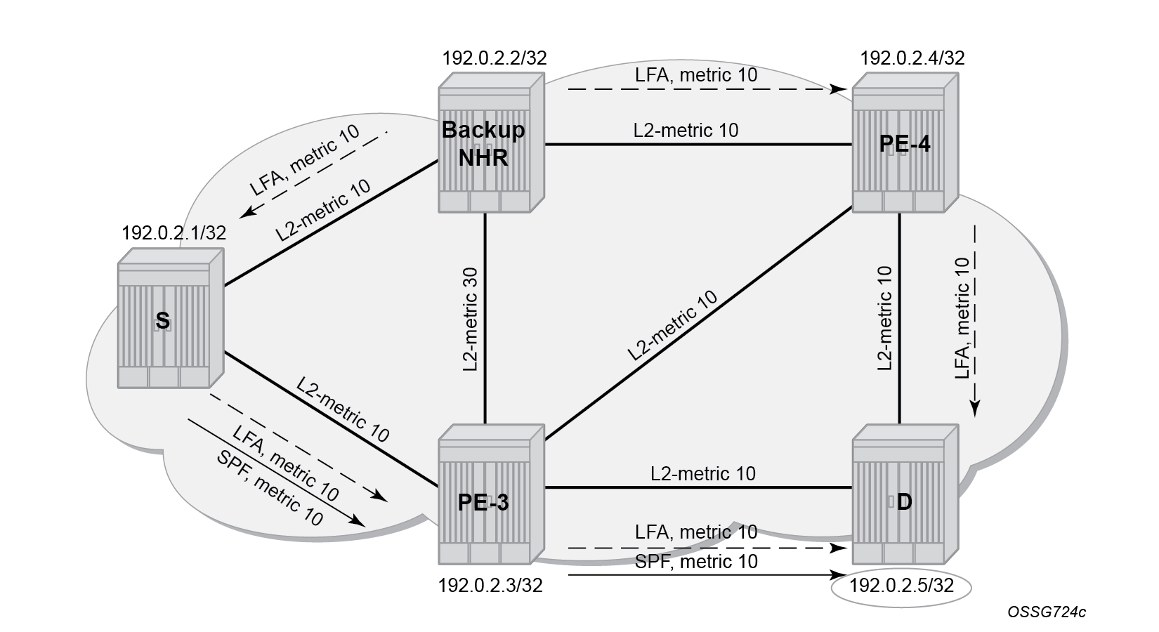
The SR Linux software has implemented inequality 1 (link criterion) and inequality 3 (node criterion) of RFC 5286. The LFA next hop computation is based on the IGP metric, similar to the Shortest Path Tree (SPT) computation that is part of standard link-state routing functionality, .
The underlying LFA formulas appear in the following format:
Inequality 1:
SP(backup NHR, D) < SP(backup NHR, S) + SP(S, D)Inequality 3:
SP(backup NHR, D) < SP(backup NHR, PN) + SP(PN, D)- SP is shortest IGP metric path
- NHR is next hop router
- D is destination
- S is source node or upstream node doing the actual LFA next-hop computation
- PN is protected node
Configuration
This section includes the following:
The subsection Additional topics includes:
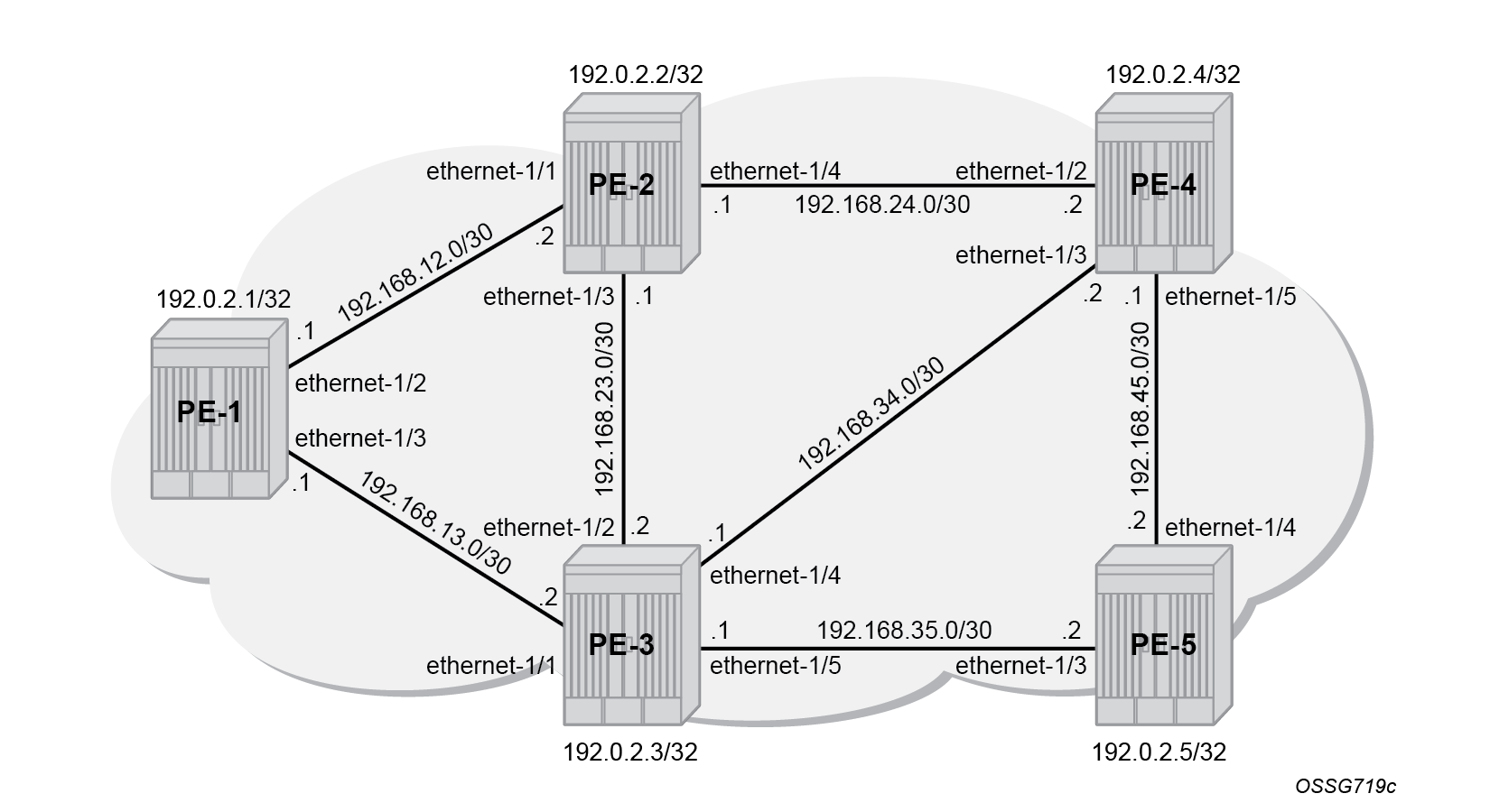
Initial example topology shows the example topology with five PEs in the same autonomous system.
Configure the IP/MPLS network
The system addresses and IP interface addresses are configured according to Initial example topology. An interior gateway protocol (IGP) is needed to distribute routing information to all PEs. In this case, the IGP is IS-IS where each PE is acting as a level 2 router. On PE-1, the IS-IS configuration is as follows. The configuration is similar on the other PEs.
# On PE-1:
enter candidate
    network-instance default protocols isis instance 0 {
                    admin-state enable
                    level-capability L2
                    net [
                        49.0000.1920.0000.2001.00
                    ]
                    interface ethernet-1/2.0 {
                        admin-state enable
                        circuit-type point-to-point
                    }
                    interface ethernet-1/3.0 {
                        admin-state enable
                        circuit-type point-to-point
                    }
                    interface system0.0 {
                    }
                    level 2 {
                    }
IS-IS interfaces are set up as type point-to-point to improve convergence because no Designated Router/Backup Designated Router (DR/BDR) election process is done. The show / network-instance default protocols isis adjacency command on PE-1 verifies that the IS-IS adjacencies are up:
--{ + running }--[  ]--
A:admin@PE-1# show / network-instance default protocols isis adjacency
----------------------------------------------------------------------------------------------------------------------------------------------
Network Instance: default
Instance        : 0
Instance Id     : 0
+----------------+--------------------+-----------------+--------------+--------------+-------+--------------------------+--------------------
| Interface Name | Neighbor System Id | Adjacency Level |  Ip Address  | Ipv6 Address | State |     Last transition      | Remaining holdtime
+================+====================+=================+==============+==============+=======+==========================+====================
| ethernet-1/2.0 | 1920.0000.2002     | L2              | 192.168.12.2 | ::           | up    | 2026-10-27T07:40:55.400Z | 26
| ethernet-1/3.0 | 1920.0000.2003     | L2              | 192.168.13.2 | ::           | up    | 2026-10-27T07:41:08.100Z | 21
+----------------+--------------------+-----------------+--------------+--------------+-------+--------------------------+--------------------
----------------------------------------------------------------------------------------------------------------------------------------------
Adjacency Count: 2
----------------------------------------------------------------------------------------------------------------------------------------------
The show / network-instance default ipv4 route command verifies which IP interface addresses or subnets are known on the PE:
--{ running }--[  ]--
A:admin@PE-1# show / network-instance default ipv4 route
=========================================================================================================================================================
IPv4-unicast route table for default network-instance
---------------------------------------------------------------------------------------------------------------------------------------------------------
Flags: > (best), * (unviable), ! (failed)
     : L (leaked route from another network-instance)
     : B (backup NHG active and displayed)
     : S (statistics supported)
     : D (dynamic LB), R (resilient LB)
---------------------------------------------------------------------------------------------------------------------------------------------------------
Prefix               Route Type   Metric   Pref    Flags    Next-Hop(s)
---------------------------------------------------------------------------------------------------------------------------------------------------------
192.0.2.2/32         isis         10       18      >        192.168.12.2(ethernet-1/2.0)
192.0.2.3/32         isis         10       18      >        192.168.13.2(ethernet-1/3.0)
192.0.2.4/32         isis         20       18      >        192.168.12.2(ethernet-1/2.0)
192.0.2.5/32         isis         20       18      >        192.168.13.2(ethernet-1/3.0)
192.168.12.0/30      local        0        0       >        192.168.12.1(ethernet-1/2.0)
192.168.13.0/30      local        0        0       >        192.168.13.1(ethernet-1/3.0)
192.168.23.0/30      isis         20       18      >        192.168.12.2(ethernet-1/2.0)
192.168.24.0/30      isis         20       18      >        192.168.12.2(ethernet-1/2.0)
192.168.34.0/30      isis         20       18      >        192.168.13.2(ethernet-1/3.0)
192.168.35.0/30      isis         20       18      >        192.168.13.2(ethernet-1/3.0)
192.168.45.0/30      isis         30       18      >        192.168.12.2(ethernet-1/2.0)

{ + running }--[  ]--
A:admin@PE-1# info from state / network-instance default route-table ipv4-unicast route * id * route-type * route-owner * origin-network-instance * | as table | filter fields
active metric preference next-hop-group next-hop-group-network-instance
+---------------+-------------------+-----------+-----------------+---------------+---------------+-------+-----------+-----------+--------------------+---------------+
|   Network-    |    Ipv4-prefix    |    Id     |   Route-type    |  Route-owner  |    Origin-    | Activ |  Metric   | Preferenc |   Next-hop-group   |   Next-hop-   |
|   instance    |                   |           |                 |               |   network-    |   e   |           |     e     |                    |    group-     |
|               |                   |           |                 |               |   instance    |       |           |           |                    |   network-    |
|               |                   |           |                 |               |               |       |           |           |                    |   instance    |
+===============+===================+===========+=================+===============+===============+=======+===========+===========+====================+===============+
| default       | 192.0.2.1/32      |         8 | host            | net_inst_mgr  | default       | true  |         0 |         0 |           34341615 | default       |
| default       | 192.0.2.2/32      |         0 | isis            | isis_mgr      | default       | true  |        10 |        18 |           34341623 | default       |
| default       | 192.0.2.3/32      |         0 | isis            | isis_mgr      | default       | true  |        10 |        18 |           34341627 | default       |
| default       | 192.0.2.4/32      |         0 | isis            | isis_mgr      | default       | true  |        20 |        18 |           34341623 | default       |
| default       | 192.0.2.5/32      |         0 | isis            | isis_mgr      | default       | true  |        20 |        18 |           34341627 | default       |
| default       | 192.168.12.0/30   |         6 | local           | net_inst_mgr  | default       | true  |         0 |         0 |           34341622 | default       |
| default       | 192.168.12.1/32   |         6 | host            | net_inst_mgr  | default       | true  |         0 |         0 |           34341621 | default       |
| default       | 192.168.12.3/32   |         6 | host            | net_inst_mgr  | default       | true  |         0 |         0 |           34341618 | default       |
| default       | 192.168.13.0/30   |         7 | local           | net_inst_mgr  | default       | true  |         0 |         0 |           34341626 | default       |
| default       | 192.168.13.1/32   |         7 | host            | net_inst_mgr  | default       | true  |         0 |         0 |           34341625 | default       |
| default       | 192.168.13.3/32   |         7 | host            | net_inst_mgr  | default       | true  |         0 |         0 |           34341618 | default       |
| default       | 192.168.23.0/30   |         0 | isis            | isis_mgr      | default       | true  |        20 |        18 |           34341623 | default       |
| default       | 192.168.24.0/30   |         0 | isis            | isis_mgr      | default       | true  |        20 |        18 |           34341623 | default       |
| default       | 192.168.34.0/30   |         0 | isis            | isis_mgr      | default       | true  |        20 |        18 |           34341627 | default       |
| default       | 192.168.35.0/30   |         0 | isis            | isis_mgr      | default       | true  |        20 |        18 |           34341627 | default       |
| default       | 192.168.45.0/30   |         0 | isis            | isis_mgr      | default       | true  |        30 |        18 |           34341623 | default       |
+---------------+-------------------+-----------+-----------------+---------------+---------------+-------+-----------+-----------+--------------------+---------------+
Initially, the default IS-IS Level 2 metric (10) applies to all interfaces.
The next step in the process of setting up the IP/MPLS network is setting up interface-LDP sessions on all interfaces. The LDP configuration on PE-1 is as follows:
# On PE-1:
# Configure LDP dynamic label block - on all nodes
enter candidate
    system mpls label-ranges dynamic dlb-ldp {
                    start-label 20000
                    end-label 20999

# Configure LDP sessions - per node
enter candidate
    network-instance default protocols ldp {
                admin-state enable
                dynamic-label-block dlb-ldp
                discovery {
                    interfaces {
                        interface ethernet-1/2.0 {
                            ipv4 {
                                admin-state enable
                            }
                        }
                        interface ethernet-1/3.0 {
                            ipv4 {
                                admin-state enable
                            }
                        }
                    }
                }
The routes in the IPv4 route table remain the same. There is now a full mesh of LDP label switched paths (LSPs) set up between all system interfaces of the PEs. The LSPs are visible in the MPLS route table.
--{ running }--[  ]--
A:admin@PE-1# show / network-instance default route-table mpls
+---------+-----------+-------------+-----------------+------------------------+----------------------+------------------+
| Label   | Operation | Type        | Next Net-Inst   | Next-hop IP (Type)     | Next-hop             | Next-hop MPLS    |
|         |           |             |                 |                        | Subinterface         | labels           |
+=========+===========+=============+=================+========================+======================+==================+
| 20000   | POP       | ldp         | default         |                        |                      |                  |
| 20001   | SWAP      | ldp         | N/A             | 192.168.12.2 (mpls)    | ethernet-1/2.0       | 20000            |
| 20002   | SWAP      | ldp         | N/A             | 192.168.13.2 (mpls)    | ethernet-1/3.0       | 20000            |
| 20003   | SWAP      | ldp         | N/A             | 192.168.12.2 (mpls)    | ethernet-1/2.0       | 20003            |
| 20004   | SWAP      | ldp         | N/A             | 192.168.13.2 (mpls)    | ethernet-1/3.0       | 20004            |
+---------+-----------+-------------+-----------------+------------------------+----------------------+------------------+
The tunnel table on PE-1 looks as follows:
--{ running }--[  ]--
A:admin@PE-1# show / network-instance default tunnel-table ipv4
-----------------------------------------------------------------------------------------------------------------------------------------------------------------------------------------------------
IPv4 tunnel table of network-instance "default"
-----------------------------------------------------------------------------------------------------------------------------------------------------------------------------------------------------
+-----------------------------------+----------------+----------+-----+----------+---------+--------------------------+---------------------+---------------------+---------------------------------+
|            IPv4 Prefix            |  Tunnel Type   |  Tunnel  | FIB |  Metric  | Prefere |       Last Update        |   Backup Nexthops   |   Next-hop (Type)   |            Next-hop             |
|                                   |                |    ID    |     |          |   nce   |                          |                     |                     |                                 |
+===================================+================+==========+=====+==========+=========+==========================+=====================+=====================+=================================+
| 192.0.2.2/32                      | ldp            | 65537    | Y   | 10       | 9       | 2026-10-27T07:41:03.427Z |                     | 192.168.12.2 (mpls) | ethernet-1/2.0                  |
| 192.0.2.3/32                      | ldp            | 65538    | Y   | 10       | 9       | 2026-10-27T07:41:15.645Z |                     | 192.168.13.2 (mpls) | ethernet-1/3.0                  |
| 192.0.2.4/32                      | ldp            | 65539    | Y   | 20       | 9       | 2026-10-27T07:41:28.688Z |                     | 192.168.12.2 (mpls) | ethernet-1/2.0                  |
| 192.0.2.5/32                      | ldp            | 65540    | Y   | 20       | 9       | 2026-10-27T07:41:40.450Z |                     | 192.168.13.2 (mpls) | ethernet-1/3.0                  |
+-----------------------------------+----------------+----------+-----+----------+---------+--------------------------+---------------------+---------------------+---------------------------------+
-----------------------------------------------------------------------------------------------------------------------------------------------------------------------------------------------------
4 LDP tunnels, 4 active, 0 inactive
-----------------------------------------------------------------------------------------------------------------------------------------------------------------------------------------------------
The LDP LSP metric follows the IGP cost. Optionally, LSP metrics can be applied but that is beyond the scope for this chapter.
Without LFA, only a FEC that is learned from the LDP peer with the shortest path to that FEC (primary next hop) can be used in forwarding.
Enable LDP LFA and verify
Because LDP LFA is using LFA next-hop computation by the IGP, as described in RFC 5286, LFA must be enabled in the IGP context, as follows:
# On PE-1:
enter candidate
    network-instance default protocols isis instance 0 {
                loopfree-alternate {
                    admin-state enable
The info from state with-context / network-instance default protocols isis instance 0 loopfree-alternate command on PE-1 verifies that only LFA is enabled in IS-IS:
--{ running }--[  ]--
A:admin@PE-1# info from state with-context / network-instance default protocols isis instance 0 loopfree-alternate
    network-instance default {
        protocols {
            isis {
                instance 0 {
                    loopfree-alternate {
                        admin-state enable
                        augment-route-table false
                        multi-homed-prefix {
                            admin-state disable
                            preference none
                        }
                        remote-lfa {
                            admin-state disable
                            max-pq-cost 0
                            node-protect {
                                admin-state disable
                                max-pq-nodes 0
                            }
                        }
                        ti-lfa {
                            admin-state disable
                            max-sr-policy-lfa-labels 0
                            max-srv6-lfa-sids 0
                            node-protect {
                                admin-state disable
                            }
                        }
Remote LFA (RLFA) and Topology-independent LFA (TI-LFA) are disabled (by default), because they are beyond the scope of this chapter.
After enabling LFA inside the IGP context, LFA needs to be enabled within the LDP context, as follows:
# On PE-1:
enter candidate
    network-instance default protocols ldp {
            loopfree-alternate {
                admin-state enable
This chapter describes LFA for unicast LDP.
After enabling LFA for IS-IS and LDP, the software computes for each LDP FEC in the network both a primary and a backup NHLFE. The primary NHLFE corresponds to the label of the FEC received from the primary next-hop as per standard LDP resolution of the FEC prefix in the Routing Table Manager (RTM). The backup NHLFE corresponds to the label received for the same FEC from an LFA next hop.
For point-to-point interfaces, when multiple LFA next hops are found for a primary next hop, the following selection criteria are used:
-
SPF prefers the node-protect type over the link-protect type.
-
If there is more than one LFA next hop within the selected type, then SPF selects an LFA next hop with the lowest cost.
-
If there is more than one LFA next hop with the same cost, then SPF selects the first one. This is not a deterministic selection and it varies following each SPF computation.
In the example topology (see Initial example topology), all IS-IS links have a default level 2 metric of 10. This results in all four nodes and all IS-IS routes learned by PE-1 being LFA protected: the LFA node coverage on PE-1 is 4/4=100%; the LFA link coverage on PE-1 is 9/9=100%.
The show / network-instance default ipv4 route type isis command confirms that all routes are protected:
--{ running }--[  ]--
A:admin@PE-1# show / network-instance default ipv4 route type isis
=========================================================================================================================================================
IPv4-unicast route table for default network-instance
---------------------------------------------------------------------------------------------------------------------------------------------------------
Flags: > (best), * (unviable), ! (failed)
     : L (leaked route from another network-instance)
     : B (backup NHG active and displayed)
     : S (statistics supported)
     : D (dynamic LB), R (resilient LB)
---------------------------------------------------------------------------------------------------------------------------------------------------------
Prefix               Route Type   Metric   Pref    Flags    Next-Hop(s)
---------------------------------------------------------------------------------------------------------------------------------------------------------
192.0.2.2/32         isis         10       18      >        192.168.12.2(ethernet-1/2.0)
                                                              backup:192.168.13.2(ethernet-1/3.0)
192.0.2.3/32         isis         10       18      >        192.168.13.2(ethernet-1/3.0)
                                                              backup:192.168.12.2(ethernet-1/2.0)
192.0.2.4/32         isis         20       18      >        192.168.12.2(ethernet-1/2.0)
                                                              backup:192.168.13.2(ethernet-1/3.0)
192.0.2.5/32         isis         20       18      >        192.168.13.2(ethernet-1/3.0)
                                                              backup:192.168.12.2(ethernet-1/2.0)
192.168.23.0/30      isis         20       18      >        192.168.12.2(ethernet-1/2.0)
                                                              backup:192.168.13.2(ethernet-1/3.0)
192.168.24.0/30      isis         20       18      >        192.168.12.2(ethernet-1/2.0)
                                                              backup:192.168.13.2(ethernet-1/3.0)
192.168.34.0/30      isis         20       18      >        192.168.13.2(ethernet-1/3.0)
                                                              backup:192.168.12.2(ethernet-1/2.0)
192.168.35.0/30      isis         20       18      >        192.168.13.2(ethernet-1/3.0)
                                                              backup:192.168.12.2(ethernet-1/2.0)
192.168.45.0/30      isis         30       18      >        192.168.12.2(ethernet-1/2.0)
                                                              backup:192.168.13.2(ethernet-1/3.0)
All remote nodes can be reached via primary and alternate paths, as follows:
--{ + running }--[  ]--
A:admin@PE-1# info from state / network-instance default protocols ldp ipv4 bindings received-prefix-fec prefix-fec * lsr-id * label-space-id 0 next-hop * | as table | filter fields *
+--------------+-------------------+--------------+-------------------------+-----------+--------------+-------------+------------------------+--------------+
|   Network-   |  Prefix-fec fec   |  Prefix-fec  | Prefix-fec label-space- |   Index   |   Next-hop   |  Next-hop-  |       Interface        | Outer-label  |
|   instance   |                   |    lsr-id    |           id            |           |              |    type     |                        |              |
+==============+===================+==============+=========================+===========+==============+=============+========================+==============+
| default      | 192.0.2.2/32      | 192.0.2.2    |                       0 |         1 | 192.168.12.2 | primary     | ethernet-1/2.0         |              |
| default      | 192.0.2.2/32      | 192.0.2.3    |                       0 |         1 | 192.168.13.2 | alternate   | ethernet-1/3.0         |              |
| default      | 192.0.2.3/32      | 192.0.2.2    |                       0 |         1 | 192.168.12.2 | alternate   | ethernet-1/2.0         |              |
| default      | 192.0.2.3/32      | 192.0.2.3    |                       0 |         1 | 192.168.13.2 | primary     | ethernet-1/3.0         |              |
| default      | 192.0.2.4/32      | 192.0.2.2    |                       0 |         1 | 192.168.12.2 | primary     | ethernet-1/2.0         |              |
| default      | 192.0.2.4/32      | 192.0.2.3    |                       0 |         1 | 192.168.13.2 | alternate   | ethernet-1/3.0         |              |
| default      | 192.0.2.5/32      | 192.0.2.2    |                       0 |         1 | 192.168.12.2 | alternate   | ethernet-1/2.0         |              |
| default      | 192.0.2.5/32      | 192.0.2.3    |                       0 |         1 | 192.168.13.2 | primary     | ethernet-1/3.0         |              |
+--------------+-------------------+--------------+-------------------------+-----------+--------------+-------------+------------------------+--------------+
As an example, detail for one node (PE-4) for which LFA protection is is in place, is shown as follows:
--{ + running }--[  ]--
A:admin@PE-1# show network-instance default ipv4 route 192.0.2.4/32 detail
================================================================================
Prefix: 192.0.2.4/32
--------------------------------------------------------------------------------
Active                : yes
Route Type            : isis
Route Owner           : isis_mgr, 2026-10-27T07:48:20.806Z (6 minutes ago)
Id                    : 0
Leakable              : no
Leaked                : no
Metric                : 20
Preference            : 18
Internal Tags         : isis-reach-type = 0x4
Dynamic LB            : no
Resilient Hash        : no
FIB Suppressed        : no
FIB Failed            : no
Next-Hop-Group        : 34341631
  Net-Instance        : default
  FIB Failed          : no
  Primary NH Count    : 1
  Backup NH Count     : 1
  Primary NH          : 34341625
    LB Weight         : 1
    Type              : direct
    IP Address        : 192.168.12.2
    Subinterface      : ethernet-1/2.0
  Backup NH           : 34341621
    Type              : direct
    IP Address        : 192.168.13.2
    Subinterface      : ethernet-1/3.0
The LSPs remain the same. The next hops are recomputed. The MPLS tunnel table is updated.
The show / network-instance default protocols ldp ipv4 fec received command on PE-1 verifies that LFA is enabled in LDP: a FEC that is learned from another LDP peer (LFA next hop) than from the one with the shortest path to that FEC (primary next hop) can also be used in forwarding. An example for prefix 192.0.2.4/32 is as follows:
--{ running }--[  ]--
A:admin@PE-1# show / network-instance default protocols ldp ipv4 fec received prefix 192.0.2.4/32
=========================================================================================================================================================
Net-Inst default LDP IPv4: Received FEC prefixes table (prefix=192.0.2.4/32)
=========================================================================================================================================================
Received FEC prefixes
---------------------------------------------------------------------------------------------------------------------------------------------------------
+--------------------------------------------------------------------------------------------+
| FEC prefix           Peer LDP ID                 Label                Ingress   Used in    |
|                                                                       LSR       Forwarding |
+============================================================================================+
| 192.0.2.4/32         192.0.2.2:0                 20003                true      true       |
| 192.0.2.4/32         192.0.2.3:0                 20003                true      true       |
+--------------------------------------------------------------------------------------------+
---------------------------------------------------------------------------------------------------------------------------------------------------------
Total received FEC prefixes  : 2 (2 used in forwarding)
=========================================================================================================================================================
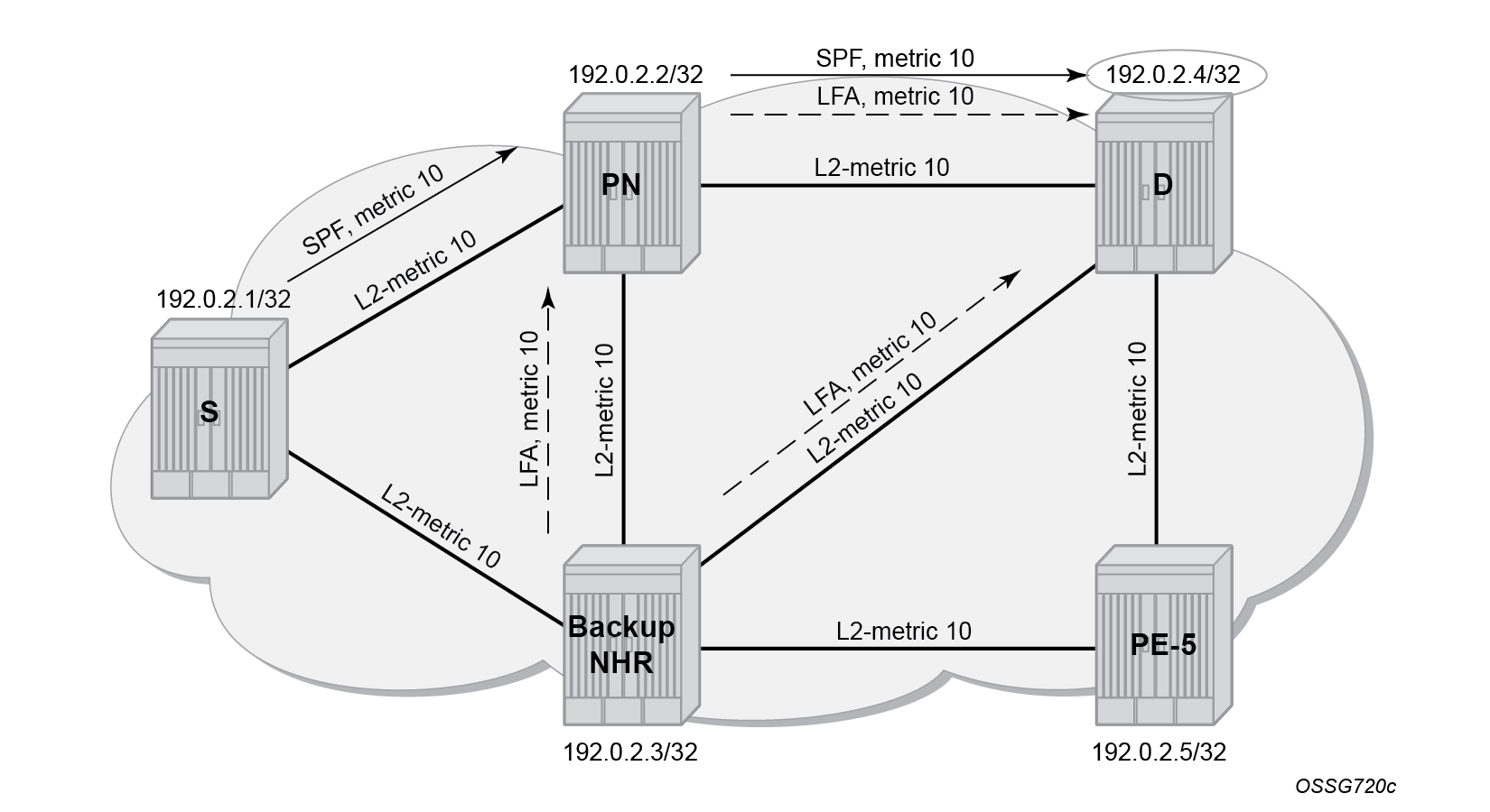
On PE-1, node PE-4 (192.0.2.4/32) has a primary SPF next-hop pointing toward PE-2 (192.168.12.2) and an LFA next-hop pointing toward PE-3 (192.168.13.2).
The inequality 3 formula on PE-1 for prefix 192.0.2.4/32 results in the following:
Inequality 3:
SP(backup NHR, D) < SP(backup NHR, PN) + SP(PN, D) or
   SP(PE-3, PE-4) < SP(PE-3, PE-2) + SP(PE-2, PE-4) or
               10 < 10 + 10 => OK
This means that inequality 3 is met. The calculated LFA next-hop for prefix 192.0.2.4/32 on PE-1 is protecting node PE-2, see LFA computation: inequality 3 for prefix PE-4 (D) on PE-1 (S) for a graphical representation.
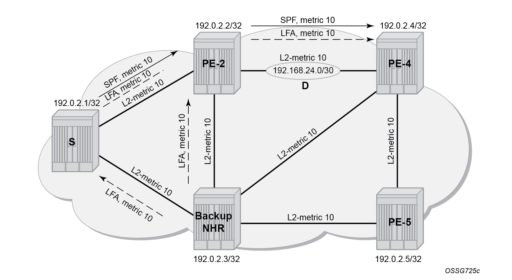
On PE-1, the link between PE-2 and PE-4 has a primary SPF next-hop pointing toward PE-2 (192.168.12.2) and an LFA next-hop pointing toward PE-3 (192.168.13.2).
The inequality 1 formula on PE-1 for prefix 192.168.24.0/30 results in the following:
Inequality 1:
SP(backup NHR, D) < SP(backup NHR, S) + SP(S, D) or
      SP(PE-3, D) < SP(PE-3, PE-1) + SP(PE-1, D) or
          10 + 10 < 10 + (10 + 10) => OK
This means that inequality 1 is also met. The calculated LFA next-hop for prefix 192.168.24.0/30 on PE-1 is protecting the link between PE-2 and PE-4, see LFA computation: inequality 1 for prefix NW 192.168.24.0/30 (D) on PE-1 (S) for a graphical representation.
Enable synchronization timer
Within an MPLS network using LDP, it is common practice to enable a synchronization timer between LDP and the IGP. Also, when LDP LFA is enabled, a situation can occur in which a synchronization timer between IGP and LDP helps: the revert scenario. When the interface for the previous primary next hop is restored, IGP may re-converge before LDP completed the FEC exchange with its neighbor over that interface. This may cause LDP to remove the LFA next hop from the FEC and blackhole traffic.
To avoid traffic being blackholed, it is recommended to enable IGP-LDP synchronization on the interface. The time is expressed in seconds and can have a value between 1 and 1800 seconds. It is also possible to configure an end-of-LIB option to optimize the synchronization time. On PE-1, the following configures the LDP synchronization timer with a value of 10 seconds on all interfaces:
# On PE-1:
enter candidate
    network-instance default protocols isis instance 0 {
                    ldp-synchronization {    # Can be configured globally or per interface.
                        hold-down-timer 10    # Metric is infinite for 10 seconds - LDP needs time to converge
                        end-of-lib true    # Restore the metric to normal after an end-of-lib message is received (meaning: LDP has all the labels from the neighbor)
The configuration on the other nodes is similar.
When this timer is enabled, the IGP advertises a link in the network with an infinite metric, when its interface is restored. When the ldp-synchronization hold-down-timer is started, LDP adjacencies are brought up together with a label exchange. When the ldp-synchronization hold-down-timer expires, the normal metric is advertised in the network again.
Verify data path
Data path verification is performed using an IP VRF service between PE-1 and PE-5. The VRF1 configuration on PE-1 is as follows:
# on PE-1:
enter candidate
    network-instance default {
        protocols {
            bgp {
                admin-state enable
                autonomous-system 64496
                router-id 192.0.2.1               # on PE-5: 192.0.2.5
                afi-safi l3vpn-ipv4-unicast {
                    admin-state enable
                }
                group grp-IBGP {
                    admin-state enable
                    peer-as 64496
                }
                neighbor 192.0.2.5 {              # on PE-5: 192.0.2.1
                    admin-state enable
                    peer-group grp-IBGP
                }
            }
        }
    }
    system {
        mpls {
            label-ranges {      # Configure dynamic label range for IP VRFs
                dynamic dlb-ip-vrfs {
                    start-label 10000
                    end-label 19999
                }
            }
            services {
                network-instance {
                    dynamic-label-block dlb-ip-vrfs
                }
            }
        }
    }
    interface lo0 {
        admin-state enable
        subinterface 0 {
            admin-state enable
            description loopback_VRF1
            ipv4 {
                admin-state enable
                address 172.31.1.1/32 {            # on PE-5: 172.16.5.1/32
                    primary
                }
            }
        }
        info
    }
    network-instance VRF1 {
        type ip-vrf
        admin-state enable
        interface lo0.0 {
            interface-ref {
                interface lo0
                subinterface 0
            }
        }
        protocols {
            bgp-ipvpn {
                bgp-instance 1 {
                    admin-state enable
                    mpls {
                        next-hop-resolution {
                            allowed-tunnel-types [
                                ldp
                            ]
                        }
                    }
                }
            }
            bgp-vpn {
                bgp-instance 1 {
                    route-distinguisher {
                        rd 192.0.2.1:1                # on PE-5: 192.0.2.5:1
                    }
                    route-target {
                        export-rt target:64496:1
                        import-rt target:64496:1
                    }
                }
            }
The VRF1 configuration on PE-5 is similar.
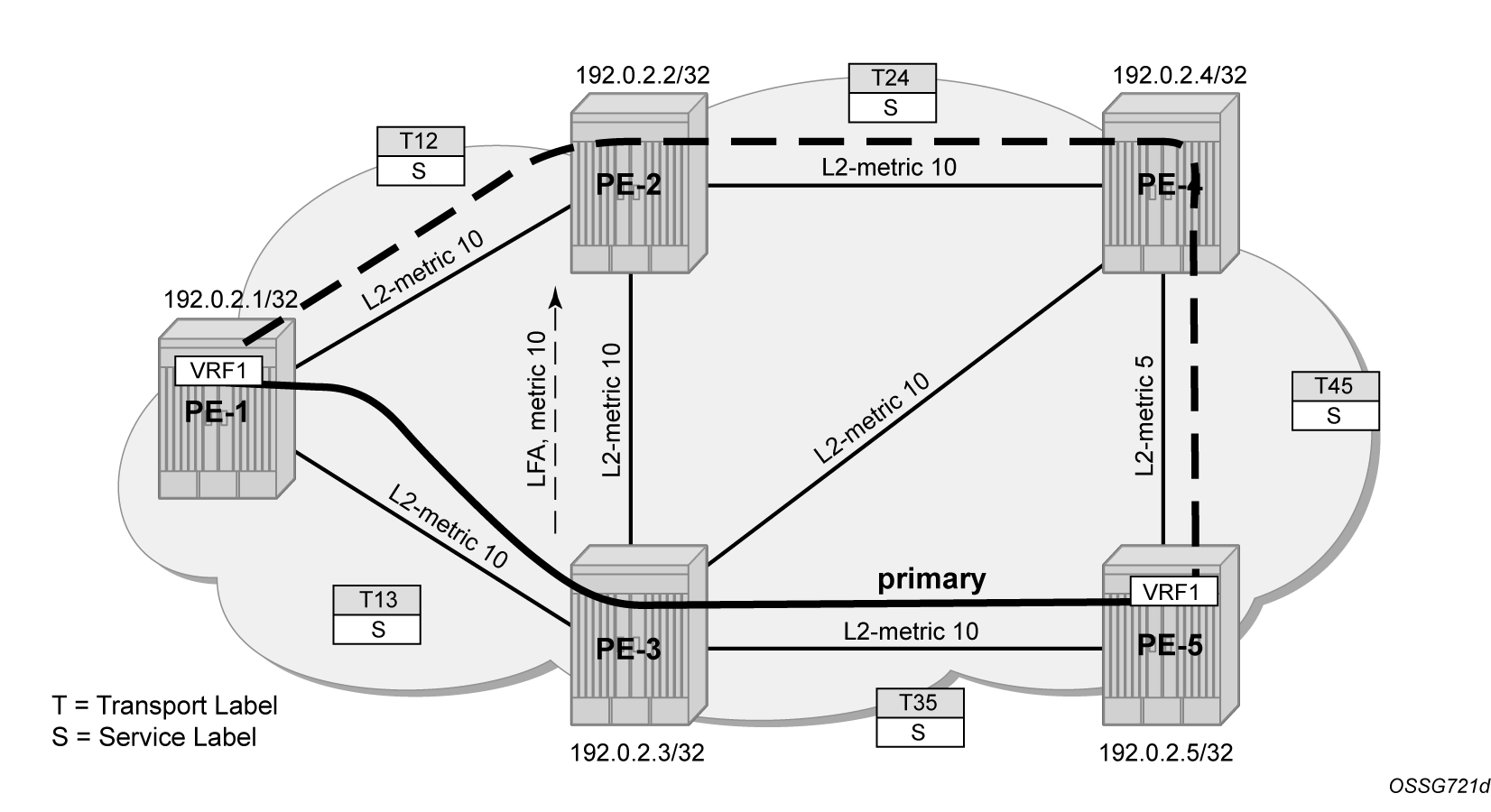
The IS-IS Level 2 metric value on the interface between PE-4 and PE-5 is decreased to 5, see Data verification for VRF1 in the direction from PE-1 to PE-5.
# On PE-4, PE-5:
enter candidate
    network-instance default protocols isis instance 0 {
                    interface ethernet-1/5.0 {    # ethernet-1/4.0 for PE-5
                        level 2 {
                            metric 5
Data verification for VRF1 in the direction from PE-1 to PE-5 shows the preferred data path for VRF1 via PE-3 and the LFA for PE-5 that is protecting node PE-3.
All routes are still protected, but the route from PE-1 to 192.168.45.0/30 has a lower overall metric:
--{ running }--[  ]--
A:admin@PE-1# show / network-instance default ipv4 route type isis
=========================================================================================================================================================
IPv4-unicast route table for default network-instance
---------------------------------------------------------------------------------------------------------------------------------------------------------
Flags: > (best), * (unviable), ! (failed)
     : L (leaked route from another network-instance)
     : B (backup NHG active and displayed)
     : S (statistics supported)
     : D (dynamic LB), R (resilient LB)
---------------------------------------------------------------------------------------------------------------------------------------------------------
Prefix               Route Type   Metric   Pref    Flags    Next-Hop(s)
---------------------------------------------------------------------------------------------------------------------------------------------------------
192.0.2.2/32         isis         10       18      >        192.168.12.2(ethernet-1/2.0)
                                                              backup:192.168.13.2(ethernet-1/3.0)
192.0.2.3/32         isis         10       18      >        192.168.13.2(ethernet-1/3.0)
                                                              backup:192.168.12.2(ethernet-1/2.0)
192.0.2.4/32         isis         20       18      >        192.168.12.2(ethernet-1/2.0)
                                                              backup:192.168.13.2(ethernet-1/3.0)
192.0.2.5/32         isis         20       18      >        192.168.13.2(ethernet-1/3.0)
                                                              backup:192.168.12.2(ethernet-1/2.0)
192.168.23.0/30      isis         20       18      >        192.168.12.2(ethernet-1/2.0)
                                                              backup:192.168.13.2(ethernet-1/3.0)
192.168.24.0/30      isis         20       18      >        192.168.12.2(ethernet-1/2.0)
                                                              backup:192.168.13.2(ethernet-1/3.0)
192.168.34.0/30      isis         20       18      >        192.168.13.2(ethernet-1/3.0)
                                                              backup:192.168.12.2(ethernet-1/2.0)
192.168.35.0/30      isis         20       18      >        192.168.13.2(ethernet-1/3.0)
                                                              backup:192.168.12.2(ethernet-1/2.0)
192.168.45.0/30      isis         25       18      >        192.168.12.2(ethernet-1/2.0)
                                                              backup:192.168.13.2(ethernet-1/3.0)
In this setup, the following LFA for prefix PE-5 from PE-1 is protecting the node PE-3:
--{ running }--[  ]--
A:admin@PE-1# show / network-instance default ipv4 route 192.0.2.5/32
=========================================================================================================================================================
IPv4-unicast route table for default network-instance
---------------------------------------------------------------------------------------------------------------------------------------------------------
Flags: > (best), * (unviable), ! (failed)
     : L (leaked route from another network-instance)
     : B (backup NHG active and displayed)
     : S (statistics supported)
     : D (dynamic LB), R (resilient LB)
---------------------------------------------------------------------------------------------------------------------------------------------------------
Prefix               Route Type   Metric   Pref    Flags    Next-Hop(s)
---------------------------------------------------------------------------------------------------------------------------------------------------------
192.0.2.5/32         isis         20       18      >        192.168.13.2(ethernet-1/3.0)
                                                              backup:192.168.12.2(ethernet-1/2.0)
In normal conditions, MPLS traffic from PE-1 toward PE-5 over VRF1 has two MPLS labels: an outer transport label provided by LDP, swapped on each intermediate LSR and an inner service label, the same end-to-end. See the following show commands.
The service label S is 10000 on PE-1 and PE-5. The LDP label range starts at 20000.
--{ + running }--[  ]--
A:admin@PE-1# show / network-instance default route-table mpls
+---------+-----------+-------------+-----------------+------------------------+----------------------+------------------+
| Label   | Operation | Type        | Next Net-Inst   | Next-hop IP (Type)     | Next-hop             | Next-hop MPLS    |
|         |           |             |                 |                        | Subinterface         | labels           |
+=========+===========+=============+=================+========================+======================+==================+
| 10000   |           | network-    | VRF1            |                        |                      |                  |
|         |           | instance    |                 |                        |                      |                  |
| 20000   | POP       | ldp         | default         |                        |                      |                  |
| 20001   | SWAP      | ldp         | N/A             | 192.168.12.2 (mpls)    | ethernet-1/2.0       | 20000            |
| 20002   | SWAP      | ldp         | N/A             | 192.168.13.2 (mpls)    | ethernet-1/3.0       | 20000            |
| 20003   | SWAP      | ldp         | N/A             | 192.168.12.2 (mpls)    | ethernet-1/2.0       | 20003            |
| 20004   | SWAP      | ldp         | N/A             | 192.168.13.2 (mpls)    | ethernet-1/3.0       | 20004            |
+---------+-----------+-------------+-----------------+------------------------+----------------------+------------------+
The transport LDP label between PE-1 and PE-3 (on the primary route) for prefix 192.0.2.5/32 is T13=20004:
--{ running }--[  ]--
A:admin@PE-1# show / network-instance default protocols ldp ipv4 fec received prefix 192.0.2.5/32
=========================================================================================================================================================
Net-Inst default LDP IPv4: Received FEC prefixes table (prefix=192.0.2.5/32)
=========================================================================================================================================================
Received FEC prefixes
---------------------------------------------------------------------------------------------------------------------------------------------------------
+--------------------------------------------------------------------------------------------+
| FEC prefix           Peer LDP ID                 Label                Ingress   Used in    |
|                                                                       LSR       Forwarding |
+============================================================================================+
| 192.0.2.5/32         192.0.2.2:0                 20004                true      true       |
| 192.0.2.5/32         192.0.2.3:0                 20004                true      true       |
+--------------------------------------------------------------------------------------------+
---------------------------------------------------------------------------------------------------------------------------------------------------------
Total received FEC prefixes  : 2 (2 used in forwarding)
=========================================================================================================================================================
The transport LDP label between PE-3 and PE-5 (on the primary route) for prefix 192.0.2.5/32 is T35=20000:
--{ running }--[  ]--
A:admin@PE-3# show / network-instance default protocols ldp ipv4 fec received prefix 192.0.2.5/32
=========================================================================================================================================================
Net-Inst default LDP IPv4: Received FEC prefixes table (prefix=192.0.2.5/32)
=========================================================================================================================================================
Received FEC prefixes
---------------------------------------------------------------------------------------------------------------------------------------------------------
+--------------------------------------------------------------------------------------------+
| FEC prefix           Peer LDP ID                 Label                Ingress   Used in    |
|                                                                       LSR       Forwarding |
+============================================================================================+
| 192.0.2.5/32         192.0.2.1:0                 20004                true      false      |
| 192.0.2.5/32         192.0.2.2:0                 20004                true      false      |
| 192.0.2.5/32         192.0.2.4:0                 20004                true      true       |
| 192.0.2.5/32         192.0.2.5:0                 20000                true      true       |
+--------------------------------------------------------------------------------------------+
---------------------------------------------------------------------------------------------------------------------------------------------------------
Total received FEC prefixes  : 4 (2 used in forwarding)
=========================================================================================================================================================
When PE-3 fails, PE-1 performs an immediate swap to LFA next-hop for prefix 192.0.2.5/32 bypassing PE-3. The failure of PE-3 is simulated in this setup by disabling network-instance default on PE-3.
# On PE-3:
enter candidate
    network-instance default {
        admin-state disable
The service label remains the same; only the transport labels can change on the network ports from PE-1 to PE-2, from PE-2 to PE-4, and from PE-4 to PE-5. See the following show commands.
The service label is still 10000.
The transport LDP label value between PE-1 and PE-2 (on the alternate route) for prefix 192.0.2.5/32 is T12=20004, the same label as before the failure of PE-3:
--{ running }--[  ]--
A:admin@PE-1# show / network-instance default protocols ldp ipv4 fec received prefix 192.0.2.5/32
=========================================================================================================================================================
Net-Inst default LDP IPv4: Received FEC prefixes table (prefix=192.0.2.5/32)
=========================================================================================================================================================
Received FEC prefixes
---------------------------------------------------------------------------------------------------------------------------------------------------------
+--------------------------------------------------------------------------------------------+
| FEC prefix           Peer LDP ID                 Label                Ingress   Used in    |
|                                                                       LSR       Forwarding |
+============================================================================================+
| 192.0.2.5/32         192.0.2.2:0                 20004                true      true       |
+--------------------------------------------------------------------------------------------+
---------------------------------------------------------------------------------------------------------------------------------------------------------
Total received FEC prefixes  : 1 (1 used in forwarding)
=========================================================================================================================================================
The transport LDP label between PE-2 and PE-4 for prefix 192.0.2.5/32 is T24=20004:
--{ running }--[  ]--
A:admin@PE-2# show / network-instance default protocols ldp ipv4 fec received prefix 192.0.2.5/32
=========================================================================================================================================================
Net-Inst default LDP IPv4: Received FEC prefixes table (prefix=192.0.2.5/32)
=========================================================================================================================================================
Received FEC prefixes
---------------------------------------------------------------------------------------------------------------------------------------------------------
+--------------------------------------------------------------------------------------------+
| FEC prefix           Peer LDP ID                 Label                Ingress   Used in    |
|                                                                       LSR       Forwarding |
+============================================================================================+
| 192.0.2.5/32         192.0.2.1:0                 20004                true      false      |
| 192.0.2.5/32         192.0.2.4:0                 20004                true      true       |
+--------------------------------------------------------------------------------------------+
---------------------------------------------------------------------------------------------------------------------------------------------------------
Total received FEC prefixes  : 2 (1 used in forwarding)
=========================================================================================================================================================
The transport LDP label between PE-4 and PE-5 for prefix 192.0.2.5/32 is T45=20000):
--{ running }--[  ]--
A:admin@PE-4# show / network-instance default protocols ldp ipv4 fec received prefix 192.0.2.5/32
=========================================================================================================================================================
Net-Inst default LDP IPv4: Received FEC prefixes table (prefix=192.0.2.5/32)
=========================================================================================================================================================
Received FEC prefixes
---------------------------------------------------------------------------------------------------------------------------------------------------------
+--------------------------------------------------------------------------------------------+
| FEC prefix           Peer LDP ID                 Label                Ingress   Used in    |
|                                                                       LSR       Forwarding |
+============================================================================================+
| 192.0.2.5/32         192.0.2.2:0                 20004                true      false      |
| 192.0.2.5/32         192.0.2.5:0                 20000                true      true       |
+--------------------------------------------------------------------------------------------+
---------------------------------------------------------------------------------------------------------------------------------------------------------
Total received FEC prefixes  : 2 (1 used in forwarding)
=========================================================================================================================================================
On PE-4 and PE-5, the default level 2 metrics are restored, as follows:
# On PE-4, PE-5:
enter candidate
    network-instance default protocols isis instance 0 {
                    interface ethernet-1/5.0 {    # ethernet-1/4.0 for PE-5
                        level 2 {
                            delete metric
Enable network-instance default on PE-3 again.
# On PE-3:
enter candidate
    network-instance default {
        admin-state enable
Additional topics
Metric change
Increase the IS-IS Level 2 metric values on the interfaces between PE-2 and PE-3 to 30. LFA paths for some nodes and links are no longer possible.
# On PE-2, PE-3:
enter candidate
    network-instance default protocols isis instance 0 {
                    interface ethernet-1/3.0 {    # ethernet-1/2.0 for PE-3
                        level 2 {
                            metric 30
On PE-1, the inequality 3 formula finds LFA next-hop coverages for prefix PE-4 and PE-5. The inequality formula 1 finds LFA next-hop coverages for prefix PE-4, PE-5, and the subnet between PE-4 and PE-5. This can be derived from:
--{ running }--[  ]--
A:admin@PE-1# show / network-instance default ipv4 route
=========================================================================================================================================================
IPv4-unicast route table for default network-instance
---------------------------------------------------------------------------------------------------------------------------------------------------------
Flags: > (best), * (unviable), ! (failed)
     : L (leaked route from another network-instance)
     : B (backup NHG active and displayed)
     : S (statistics supported)
     : D (dynamic LB), R (resilient LB)
---------------------------------------------------------------------------------------------------------------------------------------------------------
Prefix               Route Type   Metric   Pref    Flags    Next-Hop(s)
---------------------------------------------------------------------------------------------------------------------------------------------------------
192.0.2.2/32         isis         10       18      >        192.168.12.2(ethernet-1/2.0)
192.0.2.3/32         isis         10       18      >        192.168.13.2(ethernet-1/3.0)
192.0.2.4/32         isis         20       18      >        192.168.12.2(ethernet-1/2.0)
                                                              backup:192.168.13.2(ethernet-1/3.0)
192.0.2.5/32         isis         20       18      >        192.168.13.2(ethernet-1/3.0)
                                                              backup:192.168.12.2(ethernet-1/2.0)
192.168.12.0/30      local        0        0       >        192.168.12.1(ethernet-1/2.0)
192.168.13.0/30      local        0        0       >        192.168.13.1(ethernet-1/3.0)
192.168.23.0/30      isis         40       18      >        192.168.12.2(ethernet-1/2.0)
192.168.24.0/30      isis         20       18      >        192.168.12.2(ethernet-1/2.0)
192.168.34.0/30      isis         20       18      >        192.168.13.2(ethernet-1/3.0)
192.168.35.0/30      isis         20       18      >        192.168.13.2(ethernet-1/3.0)
192.168.45.0/30      isis         30       18      >        192.168.12.2(ethernet-1/2.0)
                                                              backup:192.168.13.2(ethernet-1/3.0)
Both inequality formulas are visualized in LFA computation: inequality 3 for prefix PE-5 (D) on PE-1 (S) and LFA computation: inequality 1 for prefix PE-5 (D) on PE-1 (S) for prefix 192.0.2.5/32 (= PE-5) on PE-1 which serves as the source node for LFA next-hop computation.
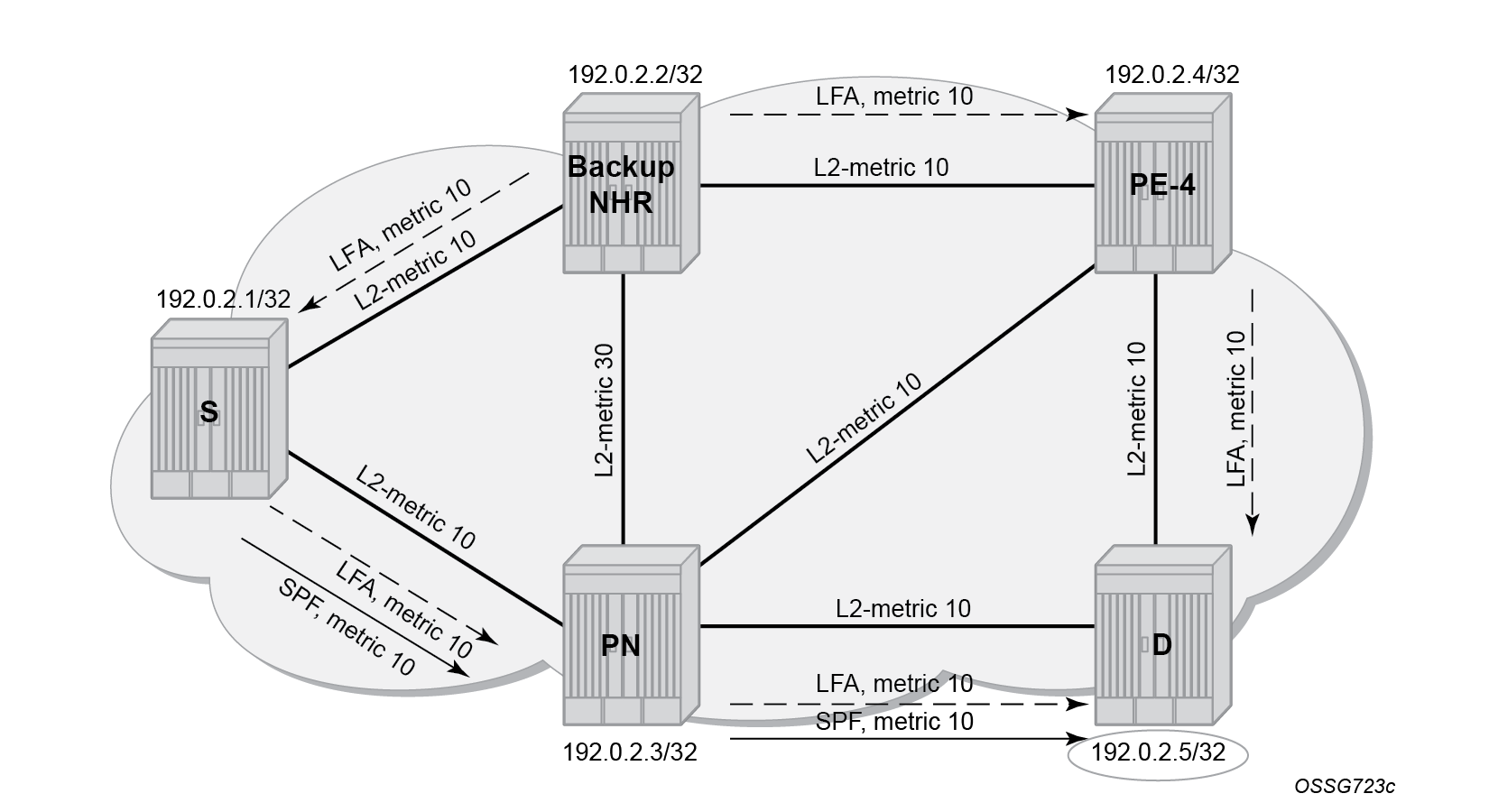
SP(backup NHR, D) < SP(backup NHR, PN) + SP(PN, D)For a node LFA next-hop computation of prefix 192.0.2.5/32 (D) on PE-1, this means that the shortest path from backup next-hop router PE-2 toward destination PE-5 must be smaller than the sum of the shortest path from backup next-hop router PE-2 toward protected node PE-3 and the shortest path from protected node PE-3 to destination PE-5.
The shortest path from backup next-hop router PE-2 toward destination PE-5 is going via PE-4, using IS-IS level 2 metric 10 for interface int-PE-2-PE-4 and IS-IS level 2 metric 10 for interface int-PE-4-PE-5. The shortest path from backup next-hop router PE-2 toward protected node PE-3 is going via PE-1, using IS-IS level 2 metric 10 for interface int-PE-2-PE-1 and IS-IS level 2 metric 10 for interface int-PE-1-PE-3. The shortest path from protected node PE-3 to destination PE-5 uses IS-IS level 2 metric 10 for interface int-PE-3-PE-5. The computation is as follows:
Prefix 192.0.2.5/32: SP(PE-2, PE-5) < SP(PE-2, PE-3) + SP(PE-3, PE-5)
                          (10 + 10) < (10 + 10) + 10 => OK
Inequality 1 formula:
SP(backup NHR, D) < SP(backup NHR, S) + SP(S, D)For a link LFA next-hop computation of prefix 192.0.2.5/32 (D) on PE-1, this means that the shortest path from backup next-hop router PE-2 toward destination PE-5 must be smaller than the sum of the shortest path from backup next-hop router PE-2 toward source PE-1 and the shortest path from source PE-1 to destination PE-5.
The shortest path from backup next-hop router PE-2 toward destination PE-5 is going over PE-4, using IS-IS level 2 metric 10 for interface int-PE-2-PE-4 and IS-IS level 2 metric 10 for interface int-PE-4-PE-5. The shortest path from backup next-hop router PE-2 toward source PE-1 uses IS-IS level 2 metric 10 for interface int-PE-2-PE-1. The shortest path from source PE-1 to destination PE-5 follows the normal SPF computation, going over PE-3, using IS-IS level 2 metric 10 for interface int-PE-1-PE-3, and IS-IS level 2 metric 10 for interface int-PE-3-PE-5.
The computation is as follows:
Prefix 192.0.2.5/32: SP(PE-2,PE-5) < SP(PE-2,PE-1) + SP(PE-1,PE-5)
                         (10 + 10) < 10 + (10 + 10) => OK
Considering all inequality 3 computations, only two out of four are valid (OK). So, the LFA node coverage on PE-1 is 2/4=50%.
Considering all inequality 1 computations, only three out of nine are valid (OK). So, the LFA IPv4 link coverage on PE-1 is 3/9=33%.
Restore the default IS-IS Level 2 metrics on PE-2 and PE-3.
IS-IS overload
As stated in RFC 3137, sometimes it is useful and desirable for a router not to be a transit node. For those cases, it is also desirable not to have that router used as transit node during the LFA next-hop computation. Within the IS-IS protocol, this is achieved by configuring IS-IS overload. When other routers detect that IS-IS overload is configured, they only use this router for packets destined for the overloaded router's directly connected networks and IP prefixes.
As an example, configure IS-IS overload on PE-2, as follows:
# On PE-2:
enter candidate
    network-instance default protocols isis instance 0 {
                    overload {
                        immediate {
                            set-bit true
The overload flag is advertised in the IS-IS link state database for LSP 1920.0000.2002.00-00 that corresponds with PE-2. This indicates to the other PEs that PE-2 is not available as a transit node and also not as a backup next hop node.
--{ running }--[  ]--
A:admin@PE-1# info from state with-context / network-instance default protocols isis instance 0 level 2
    network-instance default {
        protocols {
            isis {
                instance 0 {
                    level 2 {
                        metric-style wide
                        loopfree-alternate-exclude false
                        ---snip---
                        link-state-database {
                            lsp 1920.0000.2001.00-00 {
                                ---snip---
                            }
                            lsp 1920.0000.2002.00-00 {
                                pdu-type level-2
                                ---snip---
                                is-type 3
                                ---snip---
                                flags [
                                    overload
                                ]
                                tlvs {
                                    ---snip---
                                }
                            }
                            lsp 1920.0000.2003.00-00 {
                                ---snip---
                            }
                            lsp 1920.0000.2004.00-00 {
                                ---snip---
                            }
                            lsp 1920.0000.2005.00-00 {
                                ---snip---
                            }
The primary path from PE-1 to PE-5 goes via PE-3. This is also the case for the primary path from PE-1 to 192.168.45.0/30. There is no alternate path for the primary paths that go via PE-3. PE-3 still acts as the backup node for the primary paths that go via PE-2.
--{ + running }--[  ]--
A:admin@PE-1# info from state / network-instance default protocols ldp ipv4 bindings received-prefix-fec prefix-fec * lsr-id * label-space-id 0 next-hop * | as table | filter fields *
+---------------+--------------------+---------------+-------------------------+-----------+---------------+--------------+------------------------+---------------+
|   Network-    |   Prefix-fec fec   |  Prefix-fec   | Prefix-fec label-space- |   Index   |   Next-hop    |  Next-hop-   |       Interface        |  Outer-label  |
|   instance    |                    |    lsr-id     |           id            |           |               |     type     |                        |               |
+===============+====================+===============+=========================+===========+===============+==============+========================+===============+
| default       | 192.0.2.2/32       | 192.0.2.2     |                       0 |         1 | 192.168.12.2  | primary      | ethernet-1/2.0         |               |
| default       | 192.0.2.2/32       | 192.0.2.3     |                       0 |         1 | 192.168.13.2  | alternate    | ethernet-1/3.0         |               |
| default       | 192.0.2.3/32       | 192.0.2.3     |                       0 |         1 | 192.168.13.2  | primary      | ethernet-1/3.0         |               |
| default       | 192.0.2.4/32       | 192.0.2.3     |                       0 |         1 | 192.168.13.2  | primary      | ethernet-1/3.0         |               |
| default       | 192.0.2.5/32       | 192.0.2.3     |                       0 |         1 | 192.168.13.2  | primary      | ethernet-1/3.0         |               |
+---------------+--------------------+---------------+-------------------------+-----------+---------------+--------------+------------------------+---------------+
Only three paths from PE-1 are LFA protected.
--{ running }--[  ]--
A:admin@PE-1# show / network-instance default ipv4 route
=========================================================================================================================================================
IPv4-unicast route table for default network-instance
---------------------------------------------------------------------------------------------------------------------------------------------------------
Flags: > (best), * (unviable), ! (failed)
     : L (leaked route from another network-instance)
     : B (backup NHG active and displayed)
     : S (statistics supported)
     : D (dynamic LB), R (resilient LB)
---------------------------------------------------------------------------------------------------------------------------------------------------------
Prefix               Route Type   Metric   Pref    Flags    Next-Hop(s)
---------------------------------------------------------------------------------------------------------------------------------------------------------
192.0.2.2/32         isis         10       18      >        192.168.12.2(ethernet-1/2.0)
                                                              backup:192.168.13.2(ethernet-1/3.0)
192.0.2.3/32         isis         10       18      >        192.168.13.2(ethernet-1/3.0)
192.0.2.4/32         isis         20       18      >        192.168.13.2(ethernet-1/3.0)
192.0.2.5/32         isis         20       18      >        192.168.13.2(ethernet-1/3.0)
192.168.12.0/30      local        0        0       >        192.168.12.1(ethernet-1/2.0)
192.168.13.0/30      local        0        0       >        192.168.13.1(ethernet-1/3.0)
192.168.23.0/30      isis         20       18      >        192.168.12.2(ethernet-1/2.0)
                                                              backup:192.168.13.2(ethernet-1/3.0)
192.168.24.0/30      isis         20       18      >        192.168.12.2(ethernet-1/2.0)
                                                              backup:192.168.13.2(ethernet-1/3.0)
192.168.34.0/30      isis         20       18      >        192.168.13.2(ethernet-1/3.0)
192.168.35.0/30      isis         20       18      >        192.168.13.2(ethernet-1/3.0)
192.168.45.0/30      isis         30       18      >        192.168.13.2(ethernet-1/3.0)
With IS-IS set-bit true on PE-2 configured with default settings for overload, the LFA coverage on PE-1 changes as follows.
Considering all inequality 3 computations, only one out of four is valid (OK): node protection is only possible for prefix 192.0.2.2/32. So, the LFA node coverage on PE-1 is 1/4=25%.
Considering all inequality 1 computations, only three out of nine are valid (OK). So, the LFA IPv4 link coverage on PE-1 is 3/9=33%.
On PE-1, only three inequality 1 computations are possible, as seen in the previous show commands. The inequality 1 computation on PE-1 for destination 192.168.24.0/30 is as follows:
SP(backup NHR,D) < SP(backup NHR,S) + SP(S,D)
      SP(PE-3,D) < SP(PE-3,PE-1) + SP(PE-1,D)
         10 + 10 < 10 + (10 + 10) => OK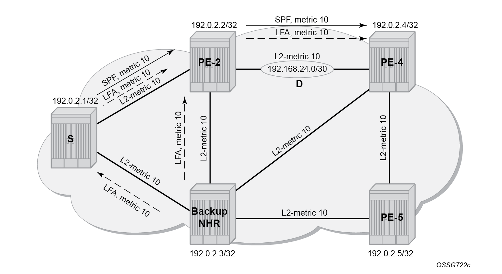
Remove the overload configuration on PE-2, as follows:
# On PE-2:
enter candidate
    network-instance default protocols isis instance 0 {
                    delete overload
Conclusion
In production MPLS networks where LFA needs to be deployed, LDP LFA improves convergence in case of a single link or single node failure in the network. The two main advantages of using LDP LFA are the simple configuration and the fact that LFA next-hop computation is a local decision, which means there are no interoperability issues when working in a multi-vendor environment. The main disadvantage of using LDP LFA is that LFA next-hop computation has to deal with the source-route paradigm (inequality formulas exclude a path going over the original source router).