NAT Stateless Dual-Homing
This chapter describes NAT stateless dual-homing.
Topics in this chapter include:
Applicability
The information and configuration in this chapter are based on SR OS Release 14.0.R4.
Overview
With the IPv4 address space almost consumed, many operators are deploying Network Address Translation (NAT) at centralized or semi-centralized points in their IP/MPLS networks. The NAT function is implemented using Carrier Grade NAT (CGN) nodes, which typically support tens of thousands of clients/subscribers. Therefore, a failure of one of these nodes would be considered a significant event.
Many operators consider a stateful failover mechanism between CGN nodes to be too demanding with regard to control plane requirements and state synchronization of NAT bindings. A reasonable compromise appears to be a stateless failover mechanism, capable of providing failover between geo-redundant CGN devices, but with manageable control plane implications.
This chapter describes the NAT stateless dual-homing feature supported in SR OS. NAT stateless dual-homing is supported for Large-Scale NAT and NAT64, and this chapter describes how both can be supported, either independently or together.
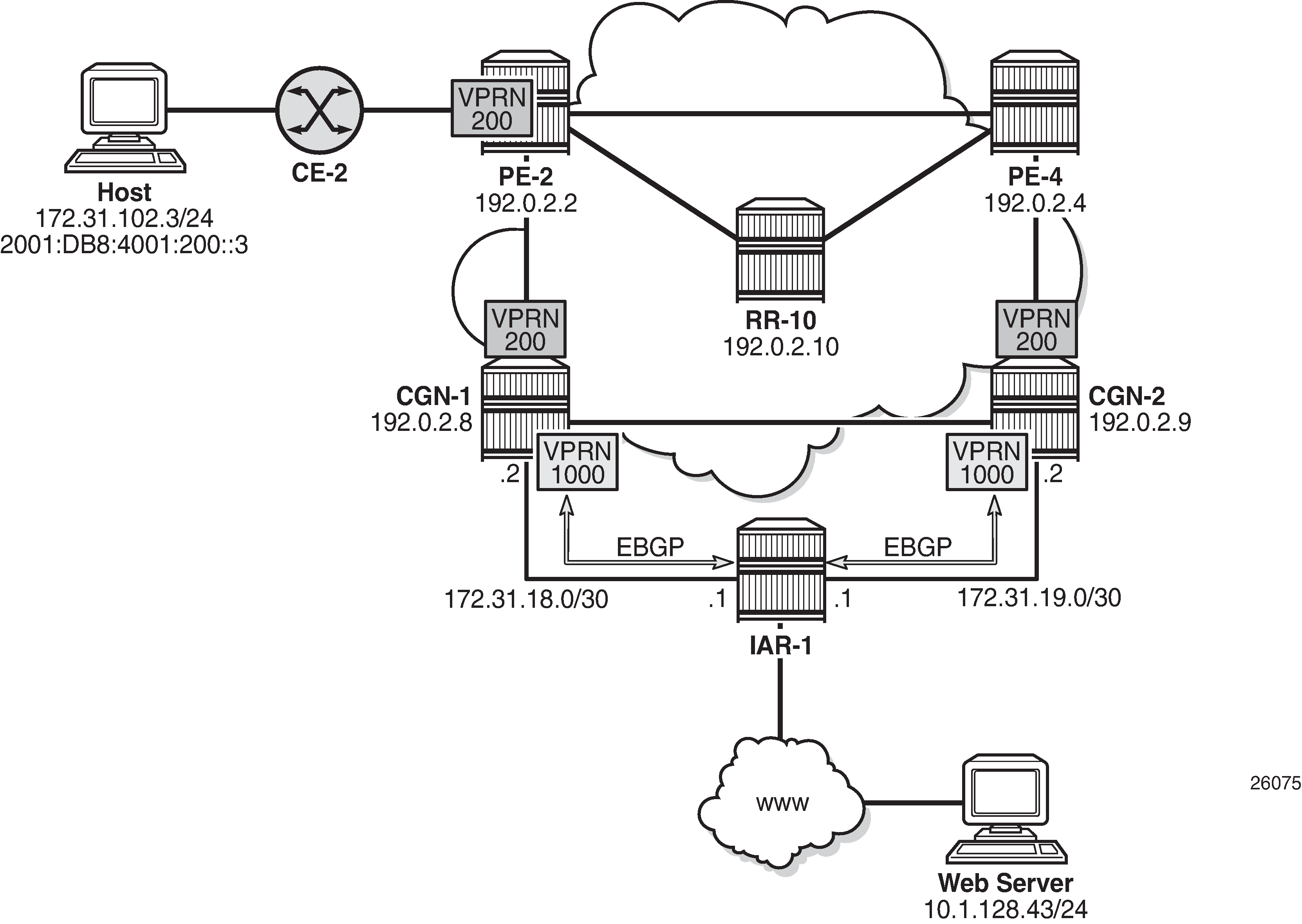
Example Topology
The topology shown in Example Topology is an example of the use of NAT stateless dual-homing. PE-2, PE-4, RR-10, CGN-1, and CGN-2 form part of Autonomous System 64496 and run IS-IS level 2 and LDP. PE-2, PE-4, CGN-1, and CGN-2 are clients of Route Reflector RR-10 and peer with the VPN-IPv4 and VPN-IPv6 address families.
IAR-1 acts as an Internet Service Provider (ISP) edge router belonging to AS 65535, and provides Internet access to AS 65596. CGN-1 and CGN-2 are configured with a VPRN (1000) that serves as a NAT outside routing VPN Routing and Forwarding (VRF) instance. In this VRF, both CGN-1 and CGN-2 peer with IAR-1 in EBGP for the IPv4 address family. CGN-1 and CGN-2 advertise the relevant NAT outside pools to IAR-1, and IAR-1 advertises a default route to both CGN-1 and CGN-2. IAR-1 has IP connectivity to a web server at 10.1.128.43/24.
CE-2 is connected to PE-2 and is part of VPRN 200. CE-2 has an IPv4 host (172.31.102.3) that serves to test NAT44 connectivity to the web server, and an IPv6 host (2001:DB8:4001:200::3) that serves to test NAT64 connectivity to the web server.
Configuration
To support NAT functionality, some form of Integrated Services Adapter (ISA) or Integrated Services Module (ISM) is required, as listed in the Applicability section. In this example, CGN-1 and CGN-2 both have a single MS-ISA card, which is configured as MDA type isa-bb, as follows:
configure
    card 1
        card-type iom3-xp-b
        mda 2
            mda-type isa-bb
            no shutdown
        exit
        no shutdown
    exit
The MS-ISA is then configured to become a member of one or more nat-group. Up to fourteen MS-ISAs can be configured to belong to up to four NAT groups. When more than one MS-ISA is configured in a NAT group, the MS-ISAs can work in active-standby mode or active-active mode.
In active-standby mode, one or more MS-ISAs act as standby, and in normal operation, are idle. If an active MS-ISA fails, one standby MS-ISA accepts the traffic from the failed card. In the active-standby scenario, the mapping between failed card and standby card can always be considered to be 1:1. In active-active mode, all of the MS-ISAs in the NAT group are active, and if one MS-ISA in the group fails, the load is distributed across the remaining active MS-ISAs in the group.
The default setting is active-standby. In both active-standby and active-active modes, the dynamically created NAT bindings are not synchronized between cards. Therefore, a failover will cause an interruption in traffic until the NAT bindings are re-initiated by the clients/subscribers behind the NAT.
The NAT group also requires that an active-mda-limit is configured, as follows, which allows the operator to specify how many MDAs (MS-ISAs) will be active in the group. Any operational MDAs above this configured limit will be considered spare MDAs. Finally, the nat-group must be placed in a no shutdown state.
configure
    isa
        nat-group 1 create
            active-mda-limit 1
            mda 1/2
            no shutdown
        exit
    exit
NAT Outside Context
The NAT outside function is responsible for creation of the NAT bindings, using outside IP addresses defined in outside pools (together with their associated ports), and for advertising the address ranges in those pools to upstream routers. The NAT stateless dual-homing redundancy mechanism is based on ownership of an outside pool, where each member of a redundant pair can assume either an active (master) or standby role for an outside pool. This active/standby role is determined by the presence of a monitor prefix. Both CGN nodes of a redundant pair implement the following:
Advertise a unique route into the routing instance that the NAT outside function resides in. This is known as the export route and may be advertised into the Global Routing Table (GRT) or a VPRN instance. For example, CGN-1 advertises (exports) prefix P1 while CGN-2 advertises prefix P2.
Check for the presence of a configured route in the routing instance that the NAT outside function resides in. This is known as the monitor route. Continuing the preceding example, CGN-1 monitors prefix P2 while CGN-2 monitors prefix P1.
Therefore, the export route of CGN-1 becomes the monitor route of CGN-2, and the export route of CGN-2 becomes the monitor route of CGN-1. The redundancy mechanism thereafter checks the (virtual) routing table of the NAT outside function for the presence of the monitor route. If it is not present, the redundancy state for the pool is set to active and the following occurs (subject to routing policy):
The redundancy export route is populated in the NAT outside routing instance and advertised externally in the relevant routing instance.
The outside pool address is populated in the NAT outside routing instance and advertised externally in the relevant routing instance.
Routes that need to become active in any associated NAT inside routing instances, to attract traffic to the active CGN node, are populated in the relevant routing tables. For example, NAT64 translator routes and/or NAT44 steering routes, both of which are described later in this chapter, are populated.
If the monitor route is present, the redundancy state for the pool is set to standby and the following occurs:
The redundancy export route is not populated in the NAT outside routing instance and is, therefore, not eligible to be advertised externally.
The outside pool address is not populated in the NAT outside routing instance and is, therefore, not eligible to be advertised externally.
Routes that need to become active in any associated NAT inside routing instances, to attract traffic to the active CGN node, are not populated in the relevant routing tables.
There are no configurable options for selection of active/standby CGN nodes. The status of a node is based on the presence of the monitor route. In the event of a collision during redundancy startup, hardcoded debounce timers ensure that only a single CGN node is selected as active.
The first of two following examples shows the configuration of VPRN 1000 (the NAT outside VRF) at CGN-2, with the second configuration showing the vrf-export and vrf-import policy statements. For advertising and importing routes from/to the VRF, there are two requirements: to advertise the export redundancy route and to import the monitor route. This is the purpose of the ‟vrf1000-export” and ‟vrf1000-import” policy statements. Other VPRN parameters are generic and, therefore, not discussed here.
The VPRN contains an interface, ‟to-IAR-1”, which has an associated EBGP peering session to IAR-1. The export policy under the BGP neighbor context will be described later in this chapter. That policy contains sufficient logic to advertise the NAT outside pools.
The NAT pools are configured in the nat>outside context. The first configuration provides an example of a single pool, ‟4-to-4”, which will be used for NAT44. As well as a name, the pool requires association with a NAT group, and definition of the type of NAT that will be configured; in this case, large-scale. The mode of the pool is set to napt to indicate N:1 NAT, and the address-range that will be used for outside addressing is 10.1.4.1 to 10.1.4.254.
The relevant and required parameters for stateless dual-homing are configured in the redundancy context. In this example, CGN-2 exports prefix 192.168.0.249/32 and monitors prefix 192.168.0.248/32. Conversely, CGN-1 exports prefix 192.168.0.248/32 and monitors prefix 192.168.0.249/32. The redundancy node and the pool must be placed into a no shutdown state.
*A:CGN-2#
configure
    service
        vprn 1000 customer 1 create
            vrf-import "vrf1000-import"
            vrf-export "vrf1000-export"
            autonomous-system 64496
            route-distinguisher 64496:1000
            auto-bind-tunnel
                resolution any
            exit
            interface "to-IAR-1" create
                address 172.31.19.2/30
                sap 1/1/2:200 create
                exit
            exit
            aggregate 10.1.4.0/24 summary-only
            bgp
                group "EBGP"
                    family ipv4
                    peer-as 65535
                    split-horizon
                    neighbor 172.31.19.1
                        authentication-key <password>
                        export "vrf1000-ebgp-export"
                    exit
                exit
                no shutdown
            exit
            nat
                outside
                    pool "4-to-4" nat-group 1 type large-scale create
                        redundancy
                            export 192.168.0.249/32
                            monitor 192.168.0.248/32
                            no shutdown
                        exit
                        mode napt
                        address-range 10.1.4.1 10.1.4.254 create
                        exit
                        no shutdown
                    exit
                exit
            exit
            service-name "NAT-Outside"
            no shutdown
        exit
    exit
*A:CGN-2#
configure
   router
        policy-options
            begin
            prefix-list "vrf1000-nat-export"
                prefix 192.168.0.249/32 exact
            exit
            community "vrf1000-export" members "target:64496:1000"
            community "vrf1000-import" members "target:64496:1000"
            policy-statement "vrf1000-export"
                entry 10
                    from
                        protocol nat
                        prefix-list "vrf1000-nat-export"
                    exit
                    to
                        protocol bgp-vpn
                    exit
                    action accept
                        community add "vrf1000-export"
                    exit
                exit
            exit
            policy-statement "vrf1000-import"
                entry 10
                    from
                        community "vrf1000-import"
                    exit
                    action accept
                    exit
                exit
                default-action drop
                exit
            exit
After the redundancy node and pool are placed into a no shutdown state, the master and standby can be elected, based on the previously described criteria. In this example, CGN-2 becomes the active CGN node for the pool ‟4-to-4”. This is shown using the following command, where the Active field shows true. Conversely, the same output at CGN-1 shows the Active field as false.
*A:CGN-2# show router 1000 nat pool "4-to-4"

===============================================================================
NAT Pool 4-to-4
===============================================================================
Description                           : (Not Specified)
ISA NAT Group                         : 1
Pool type                             : largeScale
Applications                          : (None)
Admin state                           : inService
Mode                                  : napt
Port forwarding dyn blocks reserved   : 0
Port forwarding range                 : 1 - 1023
Port reservation                      : 128 blocks
Block usage High Watermark (%)        : 90
Block usage Low Watermark (%)         : 20
Subscriber limit per IP address       : 65535
Active                                : true
Deterministic port reservation        : (Not Specified)
Last Mgmt Change                      : 10/06/2016 11:29:41
===============================================================================

===============================================================================
NAT address ranges of pool 4-to-4
===============================================================================
Range                                                          Drain Num-blk
-------------------------------------------------------------------------------
10.1.4.1 - 10.1.4.254                                                0
-------------------------------------------------------------------------------
No. of ranges: 1
===============================================================================

===============================================================================
NAT members of pool 4-to-4 ISA NAT group 1
===============================================================================
Member                                                        Block-Usage-% Hi
-------------------------------------------------------------------------------
1                                                             < 1           N
-------------------------------------------------------------------------------
No. of members: 1
===============================================================================

===============================================================================
Dual-Homing
===============================================================================
Type                                  : Leader
Export route                          : 192.168.0.249/32
Monitor route                         : 192.168.0.248/32
Admin state                           : inService
Dual-Homing State                     : Active
===============================================================================

===============================================================================
Dual-Homing fate-share-group
===============================================================================
Router         Pool                                                   Type
-------------------------------------------------------------------------------
vprn1000       4-to-4                                                 Leader
-------------------------------------------------------------------------------
No. of pools: 1
===============================================================================
Although the entire 10.1.4.0/24 block is allocated for NAT outside addressing, the address range shown in the preceding output does not include the network address (10.1.4.0/24) or broadcast address (10.1.4.255/24). Therefore, the address range does not include the entire /24 prefix and has to be fragmented into a number of longer prefixes, known through protocol NAT, to cover the 10.1.4.1-10.1.4.255 range. This is shown in the route table of VPRN 1000, following, and is due to the whole subnet not being defined in the address-range configuration. (If the address range was 10.1.4.0-10.1.4.255, there would be a single entry of 10.1.4.0/24 in the route table of VPRN 1000.)
*A:CGN-2# show router 1000 route-table 10.1.4.0/24 longer

===============================================================================
Route Table (Service: 1000)
===============================================================================
Dest Prefix[Flags]                            Type    Proto     Age        Pref
      Next Hop[Interface Name]                                    Metric
-------------------------------------------------------------------------------
10.1.4.0/24                                   Blackh* Aggr      00h01m34s  130
       Black Hole                                                   0
10.1.4.1/32                                   Remote  NAT       00h01m34s  0
       NAT outside to mda 1/2                                       0
10.1.4.2/31                                   Remote  NAT       00h01m34s  0
       NAT outside to mda 1/2                                       0
10.1.4.4/30                                   Remote  NAT       00h01m34s  0
       NAT outside to mda 1/2                                       0
10.1.4.8/29                                   Remote  NAT       00h01m34s  0
       NAT outside to mda 1/2                                       0
10.1.4.16/28                                  Remote  NAT       00h01m34s  0
       NAT outside to mda 1/2                                       0
10.1.4.32/27                                  Remote  NAT       00h01m34s  0
       NAT outside to mda 1/2                                       0
10.1.4.64/26                                  Remote  NAT       00h01m34s  0
       NAT outside to mda 1/2                                       0
10.1.4.128/26                                 Remote  NAT       00h01m34s  0
       NAT outside to mda 1/2                                       0
10.1.4.192/27                                 Remote  NAT       00h01m34s  0
       NAT outside to mda 1/2                                       0
10.1.4.224/28                                 Remote  NAT       00h01m34s  0
       NAT outside to mda 1/2                                       0
10.1.4.240/29                                 Remote  NAT       00h01m34s  0
       NAT outside to mda 1/2                                       0
10.1.4.248/30                                 Remote  NAT       00h01m34s  0
       NAT outside to mda 1/2                                       0
10.1.4.252/31                                 Remote  NAT       00h01m36s  0
       NAT outside to mda 1/2                                       0
10.1.4.254/32                                 Remote  NAT       00h01m36s  0
       NAT outside to mda 1/2                                       0
-------------------------------------------------------------------------------
No. of Routes: 15
Flags: n = Number of times nexthop is repeated
       B = BGP backup route available
       L = LFA nexthop available
       S = Sticky ECMP requested
===============================================================================
* indicates that the corresponding row element may have been truncated.
CGN-2 advertising all of these longer prefixes to the edge router of the ISP is not wanted. The ISP may even enforce a minimum /24 prefix length. Therefore, the preceding configuration of VPRN 1000 shows an aggregate command for the 10.1.4.0/24 prefix with the argument summary-only. When at least one of the more-specific prefixes in the 10.1.4.0/24 range is populated in the route table of VPRN 1000, the aggregate becomes active and can be used by the route policy for exporting to IAR-1, while suppressing the more-specific routes.
The following output shows that outside pool prefixes are not populated in the NAT outside routing context at the standby CGN node (CGN-1). Even with the aggregate command configured at both CGN nodes, the aggregate prefix will only become active at the active CGN node. Therefore, only the active CGN node will advertise that aggregate prefix upstream.
*A:CGN-1# show router 1000 route-table 10.1.4.0/24 longer

===============================================================================
Route Table (Service: 1000)
===============================================================================
Dest Prefix[Flags]                            Type    Proto     Age        Pref
      Next Hop[Interface Name]                                    Metric
-------------------------------------------------------------------------------
-------------------------------------------------------------------------------
No. of Routes: 0
Flags: n = Number of times nexthop is repeated
       B = BGP backup route available
       L = LFA nexthop available
       S = Sticky ECMP requested
===============================================================================
So far, only one pool has been defined that could be used for stateless dual-homing for both NAT44 and NAT64. However, to allow for independent address management of each of these functions, a separate outside pool is created for each. The following configuration shows two pools in the nat>outside context of VPRN 1000: the pool ‟4-to-4”, which is for NAT44 purposes, and the pool ‟6-to-4”, which is for NAT64 purposes.
The address range defined in the ‟6-to-4” pool is 10.1.6.1 to 10.1.6.254. As with the range 10.1.4.1 to 10.1.4.254 in the ‟4-to-4” pool, an aggregate command is configured to advertise the 10.1.6.0/24 prefix, while suppressing the more-specific prefixes.
With the redundancy node in the ‟6-to-4” pool, there are instances where traffic from a NAT inside routing context may be mapped to multiple outside pools, which in a stateless dual-homed environment may cause the NAT function to fail. For example, assume a NAT outside context has two pools, P1 and P2, where pool P1 is active and pool P2 is standby. An active pool can trigger the advertisement of inside and outside prefixes, and traffic will be attracted to this CGN node. When traffic arrives, it may be mapped to pool P1 on the active CGN node, due to the NAT mapping criteria. However, traffic may also be mapped to pool P2, due to the mapping criteria; this traffic will fail because the pool P2 is active on the redundant CGN node.
To ensure that this traffic failure does not happen, a group of pools accessed by the same inside routing context must all be active on the same CGN node simultaneously. To achieve this, SR OS uses a Pool Fate Sharing Group (PFSG). The PFSG ensures that all co-located pools accessed by the same inside routing context are either active or standby; not a combination of both. This is achieved by having a leader pool and follower pools.
If the leader pool is active, all follower pools are active. If the leader pool is standby, all follower pools are standby. This is enabled in the redundancy context of the ‟6-to-4” pool using the follow command. The follow command configures the pool as a follower and allows the user to access the routing context and outside pool of the leader pool. In the following example, pool ‟4-to-4” is a leader pool and pool ‟6-to-4” is a follower pool, which always assumes the same state as that of the leader.
*A:CGN-2#
configure
    service
        vprn 1000 customer 1 create
            aggregate 10.1.4.0/24 summary-only
            aggregate 10.1.6.0/24 summary-only
            nat
                outside
                    pool "4-to-4" nat-group 1 type large-scale create
                        redundancy
                            export 192.168.0.249/32
                            monitor 192.168.0.248/32
                            no shutdown
                        exit
                        mode napt
                        address-range 10.1.4.1 10.1.4.254 create
                        exit
                        no shutdown
                    exit
                    pool "6-to-4" nat-group 1 type large-scale create
                        redundancy
                            follow router 1000 pool "4-to-4"
                        exit
                        mode napt
                        address-range 10.1.6.1 10.1.6.254 create
                        exit
                        no shutdown
                    exit
                exit
            exit
The following output shows a PFSG with leaders and followers in the operational state of pool ‟6-to-4” at CGN-2. The pool state is active, but the Dual-Homing Type field indicates that this pool is a follower. Therefore, the state is derived from the state of the leader pool, which is pool ‟4-to-4” in router 1000. The output also contains a list of all the pools that are part of the same PFSG.
*A:CGN-2# show router 1000 nat pool "6-to-4"

===============================================================================
NAT Pool 6-to-4
===============================================================================
Description                           : (Not Specified)
ISA NAT Group                         : 1
Pool type                             : largeScale
Applications                          : (None)
Admin state                           : inService
Mode                                  : napt
Port forwarding dyn blocks reserved   : 0
Port forwarding range                 : 1 - 1023
Port reservation                      : 128 blocks
Block usage High Watermark (%)        : 90
Block usage Low Watermark (%)         : 20
Subscriber limit per IP address       : 65535
Active                                : true
Deterministic port reservation        : (Not Specified)
Last Mgmt Change                      : 10/06/2016 13:09:07
===============================================================================

===============================================================================
NAT address ranges of pool 6-to-4
===============================================================================
Range                                                          Drain Num-blk
-------------------------------------------------------------------------------
10.1.6.1 - 10.1.6.254                                                0
-------------------------------------------------------------------------------
No. of ranges: 1
===============================================================================

===============================================================================
NAT members of pool 6-to-4 ISA NAT group 1
===============================================================================
Member                                                        Block-Usage-% Hi
-------------------------------------------------------------------------------
1                                                             < 1           N
-------------------------------------------------------------------------------
No. of members: 1
===============================================================================

===============================================================================
Dual-Homing
===============================================================================
Type                                  : Follower
Follow-pool                           : "4-to-4" router 1000
Dual-Homing State                     : Active
===============================================================================

===============================================================================
Dual-Homing fate-share-group
===============================================================================
Router         Pool                                                   Type
-------------------------------------------------------------------------------
vprn1000       4-to-4                                                 Leader
vprn1000       6-to-4                                                 Follower
-------------------------------------------------------------------------------
No. of pools: 2
===============================================================================
NAT Policies
NAT policies allow for definition of NAT attributes such as:
filtering behavior (endpoint-independent or address-and-port-dependent)
NAT mapping timeouts
per-user session/flow limits
configuration of Application Level Gateway (ALG) protocols
high/low resource watermarks.
These attributes are generic NAT configuration parameters that are beyond the scope of this chapter.
A NAT policy also references the routing context and name of the outside pool used for the creation of NAT bindings associated with the policy. Therefore, if multiple outside pools are needed, multiple NAT policies must also be used. The following shows the configuration of the required NAT policies at CGN-2.
Because two outside pools exist in VPRN 1000 (the pool ‟4-to-4” for NAT44 and the pool ‟6-to-4” for NAT64), two policies are created using the nat-policy parameter. The nat-policy ‟NAT44” uses the pool keyword to access the ‟4-to-4” pool in router 1000, while the nat-policy ‟NAT64” uses the same pool keyword to access the ‟6-to-4” pool in router 1000. In this example, the same outside routing context is used for both NAT policies, but the outside routing contexts can also be different for each policy.
configure
    service
        nat
            nat-policy "NAT44" create
                pool "4-to-4" router 1000
            exit
            nat-policy "NAT64" create
                pool "6-to-4" router 1000
            exit
        exit
NAT Inside Context
The NAT inside routing context is the interface toward the customer or end user. There can be multiple NAT inside routing contexts mapped to a single NAT outside context (the relationship can be 1:1 or N:1). This is possible even if overlapping addresses are used in two or more NAT inside routing contexts because the NAT flow mapping tuple consists of the parameters {routing-instance, inside-IP, inside-port} mapped to {routing-instance, outside-IP, outside-port}.
The NAT inside routing context is responsible for two main functions:
Diverting some or all traffic toward the NAT function (ISA board).
Attracting traffic that should be subject to NAT toward it. This should be conditional because only the master CGNAT node should attract traffic toward itself.
For diverting traffic toward the NAT function, there are two approaches:
The first approach is to use IP filters with action nat to divert matched traffic into the ISA. Traffic subject to NAT can have a different inside and outside routing context, or the same routing context can be used for both inside and outside.
The second approach is a routing-based approach using a destination-prefix in the nat>inside context. Any traffic with a destination address matching the defined destination-prefix is forwarded to the ISA for NAT. When the destination-prefix approach is used, different routing contexts must be used for inside and outside.
For NAT44, both the IP filter and destination-prefix approaches are permitted. For NAT64, the diversion to NAT is only supported using IPv6 filters. The example setup in this chapter consists of both NAT44 and NAT64. Therefore, for the purpose of standardization across the NAT44 and NAT64 functions, the IP filter-based approach is used for both.
In Example Topology, CE-2 is connected to PE-2 and is part of VPRN 200. To provide Internet access with stateless NAT dual-homing to VPRN 200, it is extended to both CGN-1 and CGN-2 as a NAT inside VRF. The following shows the configuration of VPRN 200 at CGN-2 with a similar configuration also applied at CGN-1.
Because one of the main functions of the NAT inside routing context is to attract traffic toward the (active) CGN node, this is configured in the nat>inside context. The redundancy parameter provides a context for the configuration of NAT44 redundancy when the diversion to NAT is implemented with IP filters. In this redundancy context, the peer command is used to configure the address of the redundant peer (in this case CGN-1). If upstream traffic that is subject to NAT inadvertently arrives at the CGN node that is standby for the outside pool used for the NAT mapping, this parameter provides a forwarding address for that traffic. However, if destination-prefix based redirect to NAT is used instead of IP filters, only a nat-policy and destination-prefix need to be configured in the NAT inside routing context.
The steering-route command is optional. It allows for configuration of a (non-default) prefix/length that is only active in the routing table of the NAT inside routing context of the active CGN node. When this steering route is active in the routing table, it can either be advertised directly using the route-policy framework, or it can be used as an indirect next-hop to advertise some other prefix. This latter approach is used in the following configuration example, where the steering-route of 192.168.203.1/32 is used as an indirect next-hop for the static-route-entry of 0.0.0.0/0. This creates the following dependencies:
If the CGN node is active, the steering route of 192.168.203.1/32 becomes active in the routing table of VPRN 200.
When 192.168.203.1/32 is active, it becomes a valid indirect next-hop for 0.0.0.0/0, so this route also becomes active in the routing table.
When the default route is active, it can be exported to the rest of the VPN using the route-policy framework.
In the first of three following configurations, the vrf-export command accesses a policy with the name vrf200-export. The second configuration shows the contents of that policy, where entry 10 accesses a prefix-list (vrf200-lsn44-default) containing the default route and advertises it into BGP-VPN, with the relevant Route-Target (target:64496:200) and Origin (origin:64496:200) Extended Communities attached.
The Origin Extended Community is used by the redundant CGN peer to drop the default route, as shown in entry 10 of the corresponding vrf200-import policy in the same configuration. The reason for dropping the default route at the standby CGN node is that the vrf200-export policy only requires that a default route is present in the routing table in order to source/advertise a default route itself. If the standby CGN node imports the default route from the active CGN node into the routing table, the standby will also attempt to advertise a default route, which is not wanted.
The nat64 command provides the context to configure the NAT64 redundancy parameters. In the case of NAT64, the CGN node becomes a translator between the IPv6 and IPv4 address families and needs to advertise the NAT64 translator address that will be used by IPv6 clients to embed IPv4 addresses. In the first configuration, the address 2001:DB8:122:344::/96 is used as the NAT64 translator address. As with NAT44, the advertisement of this address is conditional and must only be advertised by the active CGN node. This is ensured because the prefix is only present in the routing table of the active CGN, not the standby CGN.
Entry 20 of the vrf200-export policy shown in the second configuration provides the relevant policy rules to ensure that this IPv6 prefix is advertised into BGP-VPN with the relevant Route-Target value when the prefix is present in the routing table.
The last parameter in the nat>inside context is the nat-policy, which is known as the default NAT policy and must exist in the nat>inside context. When multiple NAT policies are used in a single NAT inside routing context, the default NAT policy is used for any traffic that is not matched (using the destination-prefix for NAT44 or IPv4/IPv6 filters for NAT44/NAT64) and associated with an explicit NAT policy. The default NAT policy can reference a separate NAT policy, or it can reference a NAT policy that is already in use.
As previously described, the intention is to use IP filters to implement the diversion to NAT. The relevant IPv4 and IPv6 filter IDs (ID number 200 in both cases) are shown in the third configuration. The IPv4 filter has no match criteria in this example; it has action nat using nat-policy ‟NAT44”, which accesses the outside pool ‟4-to-4” in VPRN 1000. The IPv6 filter also has no match criteria and has action nat, but distinguishes between DSLite (DSLite is not supported for NAT stateless dual-homing) and NAT64, using the nat-type argument. The nat-policy that should be used is the policy ‟NAT64”, which accesses the outside pool ‟6-to-4” in VPRN 1000. These IP filters need to match traffic that ingresses the redundant CGN nodes from the MPLS side of VPRN 200 and are, therefore, applied in the network>ingress context in the first configuration.
The remainder of the VPRN parameters are generic and are not explained here.
*A:CGN-2#
configure
    service
        vprn 200 customer 1 create
            vrf-import "vrf200-import"
            vrf-export "vrf200-export"
            route-distinguisher 64496:200
            auto-bind-tunnel
                resolution any
                exit
            exit
            static-route-entry 0.0.0.0/0
                indirect 192.168.203.1
                    no shutdown
                exit
            exit
            nat
                inside
                    nat-policy "NAT44"
                    nat64
                        prefix 2001:db8:122:344::/96
                        no shutdown
                    exit
                    redundancy
                        peer 192.0.2.8
                        steering-route 192.168.203.1/32
                    exit
                exit
            exit
            network
                ingress
                    filter ip 200
                    filter ipv6 200
                exit
            exit
            no shutdown
        exit
*A:CGN-2#
configure
    router
        policy-options
            begin
            prefix-list "vrf200-lsn44-default"
                prefix 0.0.0.0/0 exact
            exit
            prefix-list "vrf200-nat64-translator"
                prefix 2001:db8:122:344::/96 exact
            exit
            community "vrf200-soo" members "origin:64496:200"
            community "vrf200-export" members "target:64496:200"
            community "vrf200-import" members "target:64496:200"
            policy-statement "vrf200-export"
                entry 10
                    from
                        prefix-list "vrf200-lsn44-default"
                    exit
                    to
                        protocol bgp-vpn
                    exit
                    action accept
                        community add "vrf200-soo" "vrf200-export"
                    exit
                exit
                entry 20
                    from
                        prefix-list "vrf200-nat64-translator"
                    exit
                    to
                        protocol bgp-vpn
                    exit
                    action accept
                        community add "vrf200-export"
                    exit
                exit
            exit
            policy-statement "vrf200-import"
                entry 10
                    from
                        community "vrf200-soo"
                    exit
                    action reject
                exit
                entry 20
                    from
                        community "vrf200-import"
                    exit
                    action accept
                    exit
                exit
            exit
*A:CGN-2#
configure
    filter
        ip-filter 200 create
            entry 10 create
                action
                    nat nat-policy "NAT44"
                exit
            exit
        exit
        ipv6-filter 200 create
            entry 10 create
                action
                    nat nat-type nat64 nat-policy "NAT64"
                exit
            exit
        exit
    exit
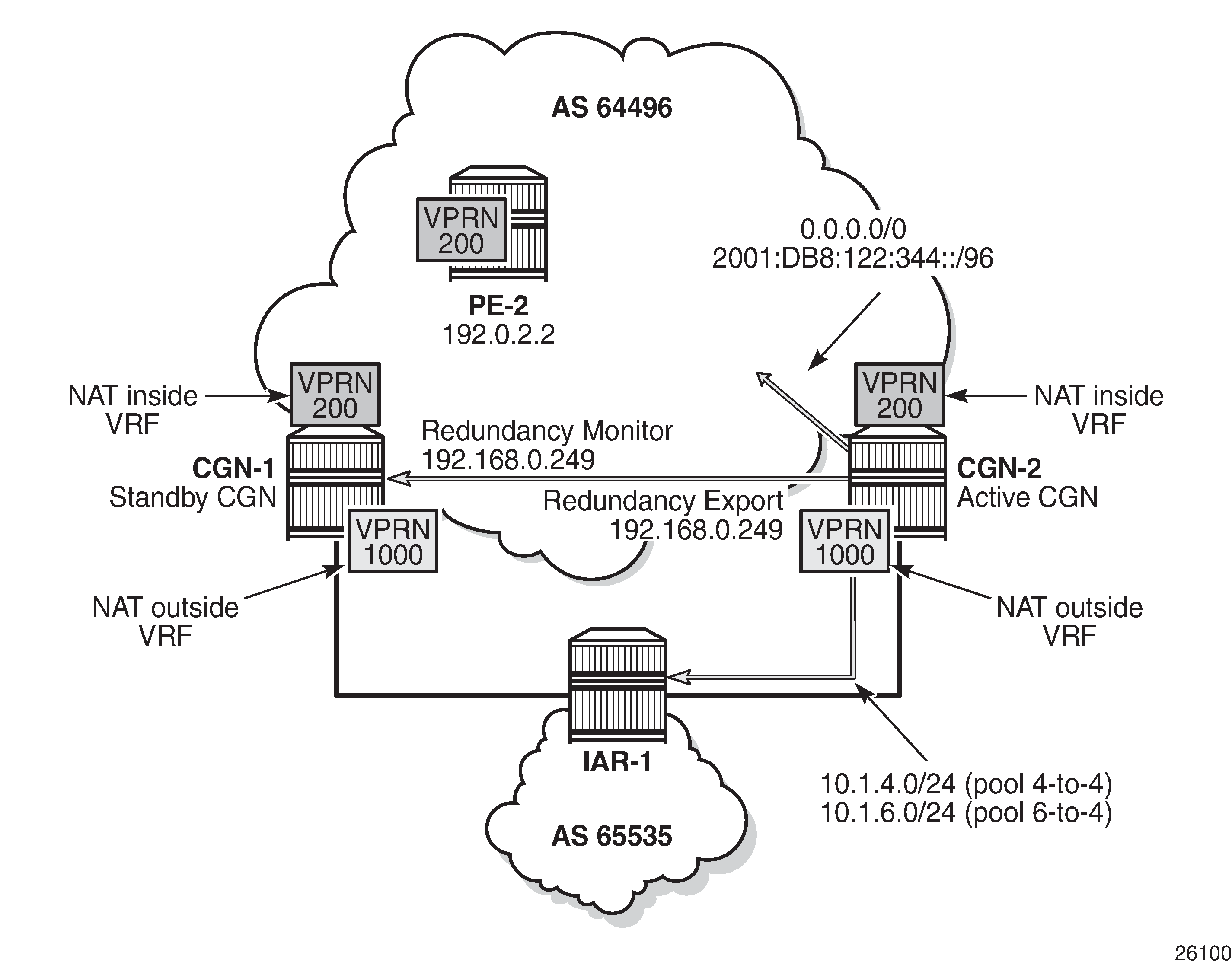
Verification of the Active CGN Node
After the configuration of the inside and NAT outside routing contexts, with the associated NAT policies, the state of the stateless redundant CGN nodes can be verified; see Redundancy Status.
The following two outputs show that the pool ‟4-to-4” is a leader at both CGN-1 and CGN-2 (for which pool ‟6-to-4” is a follower), and that CGN-2 is the active CGN node.
*A:CGN-2# show router 1000 nat pool "4-to-4" | match "Dual-Homing State" pre-lines 6
Dual-Homing
===============================================================================
Type                                  : Leader
Export route                          : 192.168.0.249/32
Monitor route                         : 192.168.0.248/32
Admin state                           : inService
Dual-Homing State                     : Active
*A:CGN-1# show router 1000 nat pool "4-to-4" | match "Dual-Homing State" pre-lines 6
Dual-Homing
===============================================================================
Type                                  : Leader
Export route                          : 192.168.0.248/32
Monitor route                         : 192.168.0.249/32
Admin state                           : inService
Dual-Homing State                     : Standby
Although the redundancy export route is populated in the NAT outside routing table and advertised externally by the active CGN node (if permitted by route-policy), it is not populated in the NAT outside routing table of the standby CGN, which is not advertised externally. The following two outputs show that CGN-2 advertises its export route (192.168.0.249/32) into IPv4 BGP-VPN, but CGN-1 does not advertise its own export route because the monitor route (192.168.0.249/32) is present.
*A:CGN-2# show router bgp routes vpn-ipv4 rd 64496:1000 hunt
---snip---
-------------------------------------------------------------------------------
RIB Out Entries
-------------------------------------------------------------------------------
Network        : 192.168.0.249/32
Nexthop        : 192.0.2.9
Route Dist.    : 64496:1000             VPN Label      : 262128
Path Id        : None
To             : 192.0.2.10
Res. Nexthop   : n/a
Local Pref.    : 100                    Interface Name : NotAvailable
Aggregator AS  : None                   Aggregator     : None
Atomic Aggr.   : Not Atomic             MED            : 0
AIGP Metric    : None
Connector      : None
Community      : target:64496:1000
Cluster        : No Cluster Members
Originator Id  : None                   Peer Router Id : 192.0.2.10
Origin         : IGP
AS-Path        : No As-Path
Route Tag      : 0
Neighbor-AS    : N/A
Orig Validation: N/A
Source Class   : 0                      Dest Class     : 0

-------------------------------------------------------------------------------
*A:CGN-1# show router 1000 route-table 192.168.0.249/32

===============================================================================
Route Table (Service: 1000)
===============================================================================
Dest Prefix[Flags]                            Type    Proto     Age        Pref
      Next Hop[Interface Name]                                    Metric
-------------------------------------------------------------------------------
192.168.0.249/32                              Remote  BGP VPN   06d03h21m  170
       192.0.2.9 (tunneled)                                         0
-------------------------------------------------------------------------------
No. of Routes: 1
Flags: n = Number of times nexthop is repeated
       B = BGP backup route available
       L = LFA nexthop available
       S = Sticky ECMP requested


*A:CGN-1# show router bgp routes vpn-ipv4 rd 64496:1000 hunt
---snip---
-------------------------------------------------------------------------------

RIB Out Entries
-------------------------------------------------------------------------------
-------------------------------------------------------------------------------
As well as the export/monitor routes, the outside pools are populated in the NAT outside routing context and advertised by the active CGN node. The outside pools are summarized as 10.1.4.0/24 (pool ‟4-to-4”) and 10.1.6.0/24 (pool ‟6-to-4‟) using the aggregate command in VPRN 1000. Because the (more-explicit) NAT outside pool addresses are only populated in the route table of the active CGN node, the aggregate will also only be populated in the routing table of the active CGN node. Therefore, the following policy is applied to the EBGP peering session with IAR-1 at both CGN-1 and CGN-2. The output following the policy example shows that CGN-2 advertises both of the NAT outside pools to IAR-1, while CGN-1 advertises no outside pool prefixes to IAR-1.
configure
    router
        policy-options
            begin
            policy-statement "vrf1000-ebgp-export"
                entry 10
                    from
                        protocol aggregate
                    exit
                    to
                        protocol bgp
                    exit
                    action accept
                        origin igp
                    exit
                exit
                default-action drop
                exit
            exit
            commit
*A:CGN-2# show router 1000 bgp neighbor 172.31.19.1 advertised-routes
===============================================================================
 BGP Router ID:192.0.2.9        AS:64496       Local AS:64496
===============================================================================
 Legend -
 Status codes  : u - used, s - suppressed, h - history, d - decayed, * - valid
                 l - leaked, x - stale, > - best, b - backup, p - purge
 Origin codes  : i - IGP, e - EGP, ? - incomplete

===============================================================================
BGP IPv4 Routes
===============================================================================
Flag  Network                                            LocalPref   MED
      Nexthop (Router)                                   Path-Id     Label
      As-Path
-------------------------------------------------------------------------------
i     10.1.4.0/24                                        n/a         None
      172.31.19.2                                         None        -
      64496
i     10.1.6.0/24                                        n/a         None
      172.31.19.2                                         None        -
      64496
-------------------------------------------------------------------------------
Routes : 2
===============================================================================

*A:CGN-1# show router 1000 bgp neighbor 172.31.18.1 advertised-routes
===============================================================================
 BGP Router ID:192.0.2.8        AS:64496       Local AS:64496
===============================================================================
 Legend -
 Status codes  : u - used, s - suppressed, h - history, d - decayed, * - valid
                 l - leaked, x - stale, > - best, b - backup, p - purge
 Origin codes  : i - IGP, e - EGP, ? - incomplete

===============================================================================
BGP IPv4 Routes
===============================================================================
Flag  Network                                            LocalPref   MED
      Nexthop (Router)                                   Path-Id     Label
      As-Path
-------------------------------------------------------------------------------
No Matching Entries Found
===============================================================================
In the NAT inside routing instance, any routes that are used to attract traffic are populated in the relevant route tables of the active CGN node and must be advertised externally. For the NAT44 function, the steering route 192.168.203.1/32 populates the route table of the active CGN node, and this route is used as an indirect next-hop for a static-route-entry to a default route. For the NAT64 function, the NAT64 translator address 2001:DB8:122:344::/96 is used to attract IPv6 traffic with IPv4-embedded addresses.
The first of the two following outputs shows that CGN-2 is advertising the NAT44 default route as a VPN-IPv4 prefix and the NAT64 translator address as a VPN-IPv6 prefix. Both routes are advertised with the relevant Route-Target for VPRN 200 (target:64496:200) and, therefore, will be imported by PE-2 and subsequently advertised to CE-2. The second output shows the same commands entered at CGN-1 and verifies that because CGN-1 is the standby CGN node, it is not advertising either VPN-IPv4/VPN-IPv6 prefix.
*A:CGN-2# show router bgp routes vpn-ipv4 rd 64496:200 hunt
===============================================================================
 BGP Router ID:192.0.2.9        AS:64496       Local AS:64496
===============================================================================
 Legend -
 Status codes  : u - used, s - suppressed, h - history, d - decayed, * - valid
                 l - leaked, x - stale, > - best, b - backup, p - purge
 Origin codes  : i - IGP, e - EGP, ? - incomplete

===============================================================================
BGP VPN-IPv4 Routes
===============================================================================
---snip---
-------------------------------------------------------------------------------
RIB Out Entries
-------------------------------------------------------------------------------
Network        : 0.0.0.0/0
Nexthop        : 192.0.2.9
Route Dist.    : 64496:200              VPN Label      : 262141
Path Id        : None
To             : 192.0.2.10
Res. Nexthop   : n/a
Local Pref.    : 100                    Interface Name : NotAvailable
Aggregator AS  : None                   Aggregator     : None
Atomic Aggr.   : Not Atomic             MED            : None
AIGP Metric    : None
Connector      : None
Community      : target:64496:200
Cluster        : No Cluster Members
Originator Id  : None                   Peer Router Id : 192.0.2.10
Origin         : IGP
AS-Path        : No As-Path
Route Tag      : 0
Neighbor-AS    : N/A
Orig Validation: N/A
Source Class   : 0                      Dest Class     : 0

-------------------------------------------------------------------------------


*A:CGN-2# show router bgp routes vpn-ipv6 rd 64496:200 hunt
===============================================================================
 BGP Router ID:192.0.2.9        AS:64496       Local AS:64496
===============================================================================
 Legend -
 Status codes  : u - used, s - suppressed, h - history, d - decayed, * - valid
                 l - leaked, x - stale, > - best, b - backup, p - purge
 Origin codes  : i - IGP, e - EGP, ? - incomplete

===============================================================================
BGP VPN-IPv6 Routes
===============================================================================
---snip---
-------------------------------------------------------------------------------
RIB Out Entries
-------------------------------------------------------------------------------
Network        : 2001:db8:122:344::/96
Nexthop        : ::ffff:192.0.2.9
Route Dist.    : 64496:200              VPN Label      : 262141
Path Id        : None
To             : 192.0.2.10
Res. Nexthop   : n/a
Local Pref.    : 100                    Interface Name : NotAvailable
Aggregator AS  : None                   Aggregator     : None
Atomic Aggr.   : Not Atomic             MED            : 0
AIGP Metric    : None
Connector      : None
Community      : target:64496:200
Cluster        : No Cluster Members
Originator Id  : None                   Peer Router Id : 192.0.2.10
Origin         : IGP
AS-Path        : No As-Path
Route Tag      : 0
Neighbor-AS    : N/A
Orig Validation: N/A
Source Class   : 0                      Dest Class     : 0

-------------------------------------------------------------------------------
*A:CGN-1# show router bgp routes vpn-ipv4 rd 64496:200 hunt
===============================================================================
 BGP Router ID:192.0.2.8        AS:64496       Local AS:64496
===============================================================================
 Legend -
 Status codes  : u - used, s - suppressed, h - history, d - decayed, * - valid
                 l - leaked, x - stale, > - best, b - backup, p - purge
 Origin codes  : i - IGP, e - EGP, ? - incomplete

===============================================================================
BGP VPN-IPv4 Routes
===============================================================================
---snip---
-------------------------------------------------------------------------------
RIB Out Entries
-------------------------------------------------------------------------------
-------------------------------------------------------------------------------


*A:CGN-1# show router bgp routes vpn-ipv6 rd 64496:200 hunt
===============================================================================
 BGP Router ID:192.0.2.8        AS:64496       Local AS:64496
===============================================================================
 Legend -
 Status codes  : u - used, s - suppressed, h - history, d - decayed, * - valid
                 l - leaked, x - stale, > - best, b - backup, p - purge
 Origin codes  : i - IGP, e - EGP, ? - incomplete

===============================================================================
BGP VPN-IPv6 Routes
===============================================================================
---snip---
-------------------------------------------------------------------------------
RIB Out Entries
-------------------------------------------------------------------------------
-------------------------------------------------------------------------------
Verification of Data Path
The host connected to CE-2 and the web server accessible from IAR-1 are used to verify the end-to-end data path for both NAT44 and NAT64.
NAT44
The host connected to CE-2 initiates an IPv4 UDP session toward the web server with a source address of 172.31.102.3 and a destination address of 10.1.128.43. The source port used is 1357, and the destination port is 80.
A two-way data transfer is verified as successful. The following output shows the details of the NAT44 binding at CGN-2, the active CGN node. The inside IP address and port are as described, while the allocated outside IP address is 10.1.4.254 using outside port 1047.
*A:CGN-2# tools dump nat sessions inside-ip 172.31.102.3

===============================================================================
Matched 1 session on Slot #1 MDA #2
===============================================================================
Owner               : LSN-Host@172.31.102.3
Router              : 200
Policy              : NAT44
FlowType            : UDP               Timeout (sec)       : 300
Inside IP Addr      : 172.31.102.3
Inside Port         : 1357
Outside IP Addr     : 10.1.4.254
Outside Port        : 1047
Foreign IP Addr     : 10.1.128.43
Foreign Port        : 80
Dest IP Addr        : 10.1.128.43
Nat Group           : 1
Nat Group Member    : 1
-------------------------------------------------------------------------------
===============================================================================
NAT64
The host connected to CE-2 also initiates an IPv6 UDP session toward the web server with a source address of 2001:DB8:4001:200::3 and a destination address of 2001:DB8:122:344::A01:802B. The destination address represents the NAT64 translator address (2001:DB8:122:344::/96) and the embedded IPv4 address (10.1.128.43) translated into colon-hexidecimal format (A01:802B). The source port is 2468 and the destination port is 80.
A two-way data transfer is verified as successful. The following output shows the details of the NAT64 binding at CGN-2. Again, the inside IPv6 address and port are as described, while the allocated outside IP address is 10.1.6.254 using outside port 1032.
*A:CGN-2# tools dump nat sessions inside-ip 2001:db8:4001:200::3

===============================================================================
Matched 1 session on Slot #1 MDA #2
===============================================================================
Owner               : NAT64-Sub@2001:db8:4001:200::3
Router              : 200
Policy              : NAT64
FlowType            : UDP               Timeout (sec)       : 300
Inside IP Addr      : 2001:db8:4001:200::3
                                        Inside Port         : 2468
Outside IP Addr     : 10.1.6.254
Outside Port        : 1032
Foreign IP Addr     : 10.1.128.43
Foreign Port        : 80
Dest IP Addr        : 10.1.128.43
Nat Group           : 1
Nat Group Member    : 1
-------------------------------------------------------------------------------
===============================================================================
Failover
Before simulating a failover test, an IPv4 UDP session is established between the host connected to CE-2 and the web server, to ensure data-path continuity during the failure.
CGN-2 is the active CGN node; to simulate a failure of the MS-ISA board, it is placed into a shutdown state.
*A:CGN-2# configure card 1 mda 2 shutdown

1 2016/10/13 15:10:21.39 UTC WARNING: SNMP #2004 Base 1/2/nat-in-ip
"Interface 1/2/nat-in-ip is not operational"

2 2016/10/13 15:10:21.39 UTC MINOR: NAT #2024 Base NAT
"The state of NAT group 1 changed to out-of-service."
Post-Failover Redundancy State shows the example topology in the post-failover redundancy state.
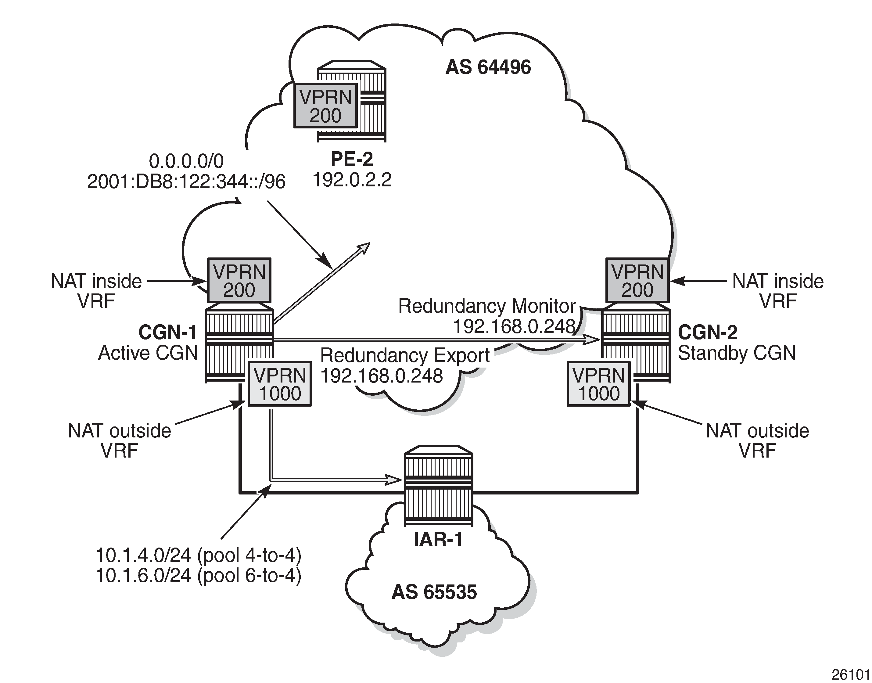
Because the MS-ISA in slot 1/2 is the only MDA in nat-group 1, it is sufficient to force the NAT group down. After nat-group 1 is declared down at CGN-2, the following actions take place:
CGN-2 transitions the active state to false for the leader outside pool and any follower pools because its admin state changed to down, as follows:
22 2016/10/13 15:10:21.40 UTC WARNING: NAT #2017 vprn1000 NAT redundancy
"The Large Scale NAT activity changed to false for pool "4-to-4" - state changed
 to "Down"."

23 2016/10/13 15:10:21.40 UTC WARNING: NAT #2017 vprn1000 NAT redundancy
"The Large Scale NAT activity changed to false for pool "6-to-4" - state changed
 to "Down"."
CGN-2 withdraws the redundancy export route (192.168.0.249/32) from the NAT outside routing context (VPRN 1000). This means that the monitor route is no longer present in the routing table of CGN-1. Therefore, CGN-1 transitions to an active state and advertises its own export route. In this example, where BGP is used to advertise monitor routes, the Minimum Route Advertisement Interval is configured for 1 second, to reduce re-convergence times. However, when the monitor route is withdrawn at the standby CGN node, the system will wait for 10 seconds to ensure that this is not a route flap before declaring itself active. This is a non-configurable timer.
6 2016/10/13 15:10:31.53 UTC WARNING: NAT #2017 vprn1000 NAT redundancy
"The Large Scale NAT activity changed to true for pool "4-to-4" - state changed
to "Active"."

8 2016/10/13 15:10:31.53 UTC WARNING: NAT #2017 vprn1000 NAT redundancy
"The Large Scale NAT activity changed to true for pool "6-to-4" - state changed
to "Active"
Because CGN-2 is now standby, the outside pool addresses are no longer present in the routing table of the outside routing context (VPRN 1000). Therefore, they are withdrawn by CGN-2 in the EBGP peering session to IAR-1. Conversely, because CGN-1 is now active, it advertises the outside pools to IAR-1.
The NAT44 redundancy steering route (192.168.203.1/32) is no longer active in the NAT inside (VPRN 200) routing table at CGN-2. Therefore, the default route no longer has a valid next-hop, so the route is withdrawn. Conversely, the steering route is now present in the routing table of VPRN 200 at CGN-1. Therefore, the default route becomes active, and is advertised into VPRN 200 as a VPN-IPv4 prefix.
The NAT64 translator address is no longer active in the NAT inside (VPRN 200) IPv6 routing table at CGN-2, so the address is withdrawn. Conversely, the NAT64 translator address is now present in the IPv6 routing table of VPRN 200 at CGN-1 and is advertised into VPRN 200 as a VPN-IPv6 prefix.
The operational state of the outside pools can be verified at CGN-1, as follows:
*A:CGN-1# show router 1000 nat pool "4-to-4" | match "Dual-Homing" post-lines 12
Dual-Homing
===============================================================================
Type                                  : Leader
Export route                          : 192.168.0.248/32
Monitor route                         : 192.168.0.249/32
Admin state                           : inService
Dual-Homing State                     : Active
===============================================================================

===============================================================================
Dual-Homing fate-share-group
===============================================================================
Router         Pool                                                   Type
-------------------------------------------------------------------------------
vprn1000       4-to-4                                                 Leader
vprn1000       6-to-4                                                 Follower
-------------------------------------------------------------------------------
No. of pools: 2
===============================================================================
Finally, the integrity of the IPv4 UDP session between the host connected to CE-2 and the web server is verified, and the associated NAT binding is shown at CGN-1, as follows:
*A:CGN-1# tools dump nat sessions inside-ip 172.31.102.3

===============================================================================
Matched 1 session on Slot #1 MDA #2
===============================================================================
Owner               : LSN-Host@172.31.102.3
Router              : 200
Policy              : NAT44
FlowType            : UDP               Timeout (sec)       : 300
Inside IP Addr      : 172.31.102.3
Inside Port         : 1357
Outside IP Addr     : 10.1.4.254
Outside Port        : 1049
Foreign IP Addr     : 10.1.128.43
Foreign Port        : 80
Dest IP Addr        : 10.1.128.43
Nat Group           : 1
Nat Group Member    : 1
-------------------------------------------------------------------------------
===============================================================================
When the failure is resolved at CGN-2 and the MS-ISA comes back online, the failover mechanism is non-revertive. This is because CGN-2 already has the CGN-1 export route present in the routing table of the NAT outside routing context (VPRN 1000) as its monitor route. The following output at CGN-2 shows the MS-ISA and NAT group 1 transitioning to in-service, followed by the active state of the outside pools changing from down to standby.
*A:CGN-2# configure card 1 mda 2 no shutdown


9 2016/10/13 15:55:10.39 UTC MINOR: NAT #2024 Base NAT
"The state of NAT group 1 changed to in-service."

10 2016/10/13 15:55:10.39 UTC MINOR: NAT #2025 Base NAT
"The NAT group 1 is not degraded."

17 2016/10/13 15:55:10.40 UTC WARNING: NAT #2017 vprn1000 NAT redundancy
"The Large Scale NAT activity changed to false for pool "4-to-4" - state changed
 to "Standby"."

18 2016/10/13 15:55:10.39 UTC WARNING: NAT #2017 vprn1000 NAT redundancy
"The Large Scale NAT activity changed to false for pool "6-to-4" - state changed
 to "Standby"."

19 2016/10/13 15:55:10.39 UTC MINOR: NAT #2020 Base NAT
"The NAT MDA 1/2 is now active in group 1."
Conclusion
NAT stateless dual-homing provides a compromise between a lack of redundancy and the protocol and state synchronization requirements for stateful NAT redundancy. This is particularly true when CGN nodes provide a gateway to the Internet where Service Level Agreements (SLAs) are often difficult to guarantee.
This chapter provides an example of how NAT stateless dual-homing is configured and describes how SR OS provides the redundancy mechanism for NAT44 and NAT64. The example in this chapter does not represent the only way that NAT stateless dual-homing can be delivered. It uses VPRNs in both the inside and outside routing contexts, but the GRT is also an option for either. It uses IP filtering for NAT diversion for both NAT44 and NAT64, but a routing-based approach using destination-prefix is also option for NAT44. It uses BGP in the NAT outside routing context and BGP-VPN in the NAT inside routing context to advertise redundancy routes externally, but any routing protocol that can be accessed through the route-policy framework is applicable.