Segment Routing – Traffic Engineered Tunnels
This chapter provides information about Segment Routing – Traffic Engineered Tunnels.
Topics in this chapter include:
Applicability
This chapter was initially written for SR OS Release 14.0.R7, but the CLI in the current edition corresponds to SR OS Release 21.2.R1.
Overview
Segment Routing (SR) is described in the chapter Segment Routing with IS-IS Control Plane, where the advertisement of node prefix segment identifiers (SIDs) cause the automatic creation of ECMP-aware shortest path MPLS tunnels on each SR-aware router. Each node prefix SID is a globally unique value and becomes an MPLS label in the MPLS data plane. The label is advertised and learned by each SR-capable router using control plane extensions to the IS-IS and OSPF protocols.
It is also possible to create source-routed traffic-engineered end-to-end segment routing paths, where routing constraints such as strict or loose hops can be used to determine a data path to be taken through a network.
These are known as Segment Routing Traffic Engineered (SR-TE) Label Switched Paths (LSPs) and use the same command line construct as that used in configuring RSVP-TE LSPs. However, SR-TE LSPs differ in that there is no mid-point state; each intermediate and tail-end router is unaware of the presence of the LSP because there is no signaling protocol used to create the path. The path can be computed locally by the ingress PE or by offloading the path computation to an external controller.
If a packet is forwarded through the SR tunnel, each router along the path will read the top label and forward the packet according to the SR tunnel table entry for that label.
This chapter describes the configuration of SR-TE LSPs with locally-computed source-routed paths and how they can be used in the data plane of Layer 2 and Layer 3 services. In the cases described, an SR-TE LSP containing a number of strict or loose hops is created at the head-end router and used to construct an LSP by translating the IP addresses configured in the MPLS path to an SID. This results in an MPLS path with state at the head end only, comprising a stack of SIDs, where each SID is an MPLS label.
In this chapter, OSPF is used to advertise the SIDs and a set of extensions to OSPF have been defined, which require additional configuration on each network router.
The LSP is instantiated—the state is operationally "up"—and a tunnel table entry is created that is owned by the SR-TE protocol. Any data packet that is resolved to use the resulting tunnel has the label stack imposed at the head-end router and is forwarded out of the appropriate next-hop interface. This interface is determined by the topmost label in the stack.
If the label is a node SID, the outgoing interface is determined by the IGP—the shortest path to the router that the node SID represents.
If the label is a local adjacency SID, the outgoing interface is the local interface for which this SID is generated by the IGP.
The segments referenced can be a prefix segment, such as a node segment or an adjacency segment, which represents a specific adjacency between two nodes. The SIDs are used as MPLS labels.
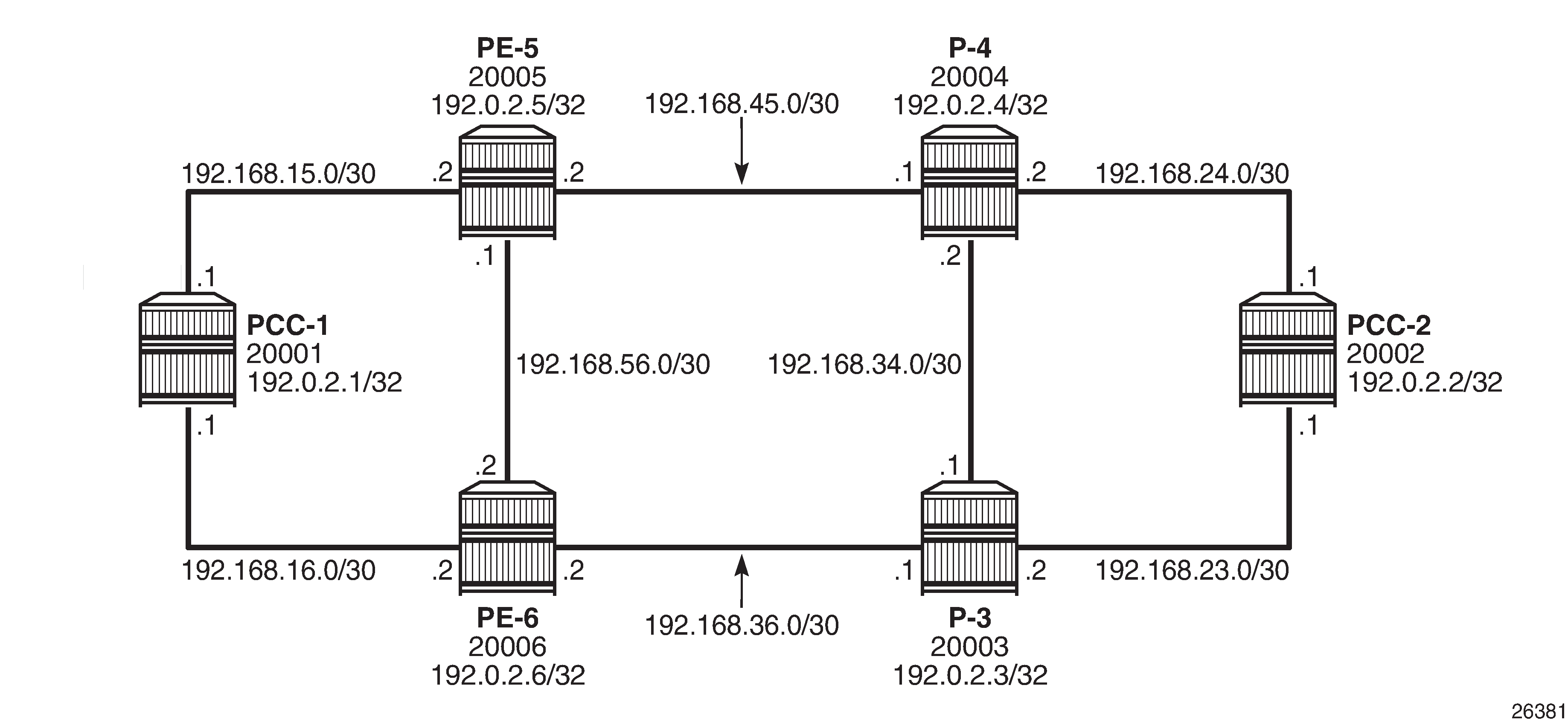
In the following configuration examples, the LSP path is created at the head-end router, and computed by translating a list of hops containing IP addresses into a list of SIDs, by examining the OSPF TE database. The head-end router is referred to as a Path Computation Client (PCC). Segment routing network schematic shows the example topology used, and a pair of bidirectional connected SR-TE LSPs between PCC-1 and PCC-2 will be configured to illustrate SR-TE LSPs. All interfaces between PCC-1 and its neighbors have the OSPF metric set to 1000. Similarly, for PCC-2, the OSPF metric is also set to 1000 between itself and its neighbors. The OSPF metric on router interfaces between the core routers P-3, P-4, PE-5, and PE-6 are set to 100.
Configuration
MPLS label range
The MPLS label range must be configured. This represents the Segment Routing Global Block (SRGB) from which node SIDs are allocated. The choice of SRGB in this example is the same as that chosen in the chapter Segment Routing with IS-IS Control Plane, where the label block is the same for each router. The SRGB is a contiguous range within the dynamic range 18432 to 524287, as shown in the following output:
*A:PCC-1# show router mpls-labels label-range

===============================================================================
Label Ranges
===============================================================================
Label Type      Start Label End Label   Aging       Available   Total
-------------------------------------------------------------------------------
Static          32          18431       -           18400       18400
Dynamic         18432       524287      0           505856      505856
Seg-Route   0           0           -           0           0
 ===============================================================================
In this example, a range of 1000 labels is chosen. For operational simplicity, Nokia recommends that the same label range is chosen for each router. However, this is not an explicit requirement.
A label range of 20000 to 20999 for SR is configured with the following command:
# on all nodes:
configure
    router Base
        mpls-labels
            sr-labels start 20000 end 20999
When the SRGB label range has been configured, the MPLS label range looks as follows:
*A:PCC-1# show router mpls-labels label-range

===============================================================================
Label Ranges
===============================================================================
Label Type      Start Label End Label   Aging       Available   Total
-------------------------------------------------------------------------------
Static          32          18431       -           18400       18400
Dynamic         18432       524287      0           504856      505856
Seg-Route   20000       20999       -           0           1000
===============================================================================
Global OSPF configuration
The first step is to configure OSPF on each router, as shown in Segment routing network schematic. All router interfaces are members of a single backbone area: area 0.0.0.0.
The configuration for PCC-1 to enable OSPF is:
# on PCC-1:
configure
    router Base
        ospf 0
            area 0.0.0.0
                interface "system"
                    no shutdown
                exit
                interface "int-PCC-1-PE-5"
                    interface-type point-to-point
                    metric 1000
                    no shutdown
                exit
                interface "int-PCC-1-PE-6"
                    interface-type point-to-point
                    metric 1000
                    no shutdown
                exit
            exit
            no shutdown
The configuration for all other nodes is the same, apart from the IP addresses. The IP addresses can be derived from Segment routing network schematic.
For each router to be segment-routing capable, additional configuration within the ospf 0 context is required. For PCC-1, this is as follows:
# on PCC-1:
configure
    router Base
        ospf 0
            traffic-engineering
            advertise-router-capability area
            segment-routing
                prefix-sid-range global
                no shutdown
            exit
            area 0.0.0.0
                interface "system"
                    node-sid label 20001
                    no shutdown
                exit
            exit
            no shutdown
The router capability is enabled using the advertise-router-capability area command, which defines the flooding scope of the opaque LSA used for this purpose as area. Traffic engineering is also enabled.
Also, MPLS must be enabled on each interface within the configure router mpls context, and RSVP must be enabled using configure router rsvp no shutdown to ensure that OSPF opaque LSAs are generated.
A node SID is manually configured as a label, equivalent to the absolute node SID value. It is possible to configure the node SID as an index. Indexing is explained in the chapter Segment Routing with IS-IS Control Plane.
Finally, segment routing is enabled, along with the prefix-sid-range command that states that the node prefix SID values of all routers within the network will be within the range of the global block.
The value of the prefix-sid-range must be the same for all routers; in this case, the range is always 1000.
The following output taken from PCC-1 shows the prefix SIDs configured on the routers in the network and advertised using OSPF. This will be identical for all routers in the network.
*A:PCC-1# show router ospf prefix-sids

=========================================================================
Rtr Base OSPFv2 Instance 0 Prefix-Sids
=========================================================================
Prefix                             Area            RtType     SID
                                   Adv-Rtr         SRMS       Flags
-------------------------------------------------------------------------
192.0.2.1/32                       0.0.0.0         INTRA-AREA 1
                                   192.0.2.1       N          NnP
192.0.2.2/32                       0.0.0.0         INTRA-AREA 2
                                   192.0.2.2       N          NnP
192.0.2.3/32                       0.0.0.0         INTRA-AREA 3
                                   192.0.2.3       N          NnP
192.0.2.4/32                       0.0.0.0         INTRA-AREA 4
                                   192.0.2.4       N          NnP
192.0.2.5/32                       0.0.0.0         INTRA-AREA 5
                                   192.0.2.5       N          NnP
192.0.2.6/32                       0.0.0.0         INTRA-AREA 6
                                   192.0.2.6       N          NnP
-------------------------------------------------------------------------
No. of Prefix/SIDs: 6
SRMS      : Y/N = prefix SID advertised by SR Mapping Server (Y) or not (N)
S   = SRMS prefix SID is selected to be programmed
SID Flags : N = Node-SID

nP = no penultimate hop POP

            M = Mapping server

            E = Explicit-Null

            V = Prefix-SID carries a value

            L = value/index has local significance

            A = Attached flag

            B = Backup flag

            I = Inter Area flag
=========================================================================
The prefix SID for each node is displayed as an index; for example, 1. The absolute value of the node SID is obtained by adding the (label_base) + (advertised SID index) = node prefix SID. The base label value for each router is chosen to be 20000, so the node prefix SID for PCC-1, for example, is 20000 + 1 = 20001.
Adjacency SIDs are generated by OSPF for each interface link, and are advertised within the extended link opaque LSA using the adjacency SID sub-TLV. The following output shows the extended link opaque LSAs of PCC-1. There are two network links, so there are two LSAs, with link state IDs of 8.0.0.3 and 8.0.0.4.
*A:PCC-1# show router ospf opaque-database adv-router 192.0.2.1 detail

===============================================================================
Rtr Base OSPFv2 Instance 0 Opaque Link State Database (type: All) (detail)
===============================================================================
---snip---
-------------------------------------------------------------------------------
Opaque LSA
-------------------------------------------------------------------------------
Area Id          : 0.0.0.0              Adv Router Id    : 192.0.2.1
Link State Id    : 8.0.0.3              LSA Type         : Area Opaque
Sequence No      : 0x80000001           Checksum         : 0x2582
Age              : 138                  Length           : 48
Options          :  E
Advertisement    : Extended Link
    TLV Extended link (1) Len 24  :
        link Type=P2P (1)  Id=192.0.2.5 Data=192.168.15.1
        Sub-TLV Adj-SID (2) len 7 :
            Flags=Value Local (0x60)
            MT-ID=0 Weight=0 SID/Index/Label=524287
-------------------------------------------------------------------------------
Opaque LSA
-------------------------------------------------------------------------------
Area Id          : 0.0.0.0              Adv Router Id    : 192.0.2.1
Link State Id    : 8.0.0.4              LSA Type         : Area Opaque
Sequence No      : 0x80000001           Checksum         : 0x1d88
Age              : 138                  Length           : 48
Options          :  E
Advertisement    : Extended Link
    TLV Extended link (1) Len 24  :
        link Type=P2P (1)  Id=192.0.2.6 Data=192.168.16.1
        Sub-TLV Adj-SID (2) len 7 :
            Flags=Value Local (0x60)
            MT-ID=0 Weight=0 SID/Index/Label=524286
===============================================================================
The adjacency SID for interface on PCC-1 toward PE-5 is 524287, and the adjacency SID for the interface toward PE-6 is 524286.
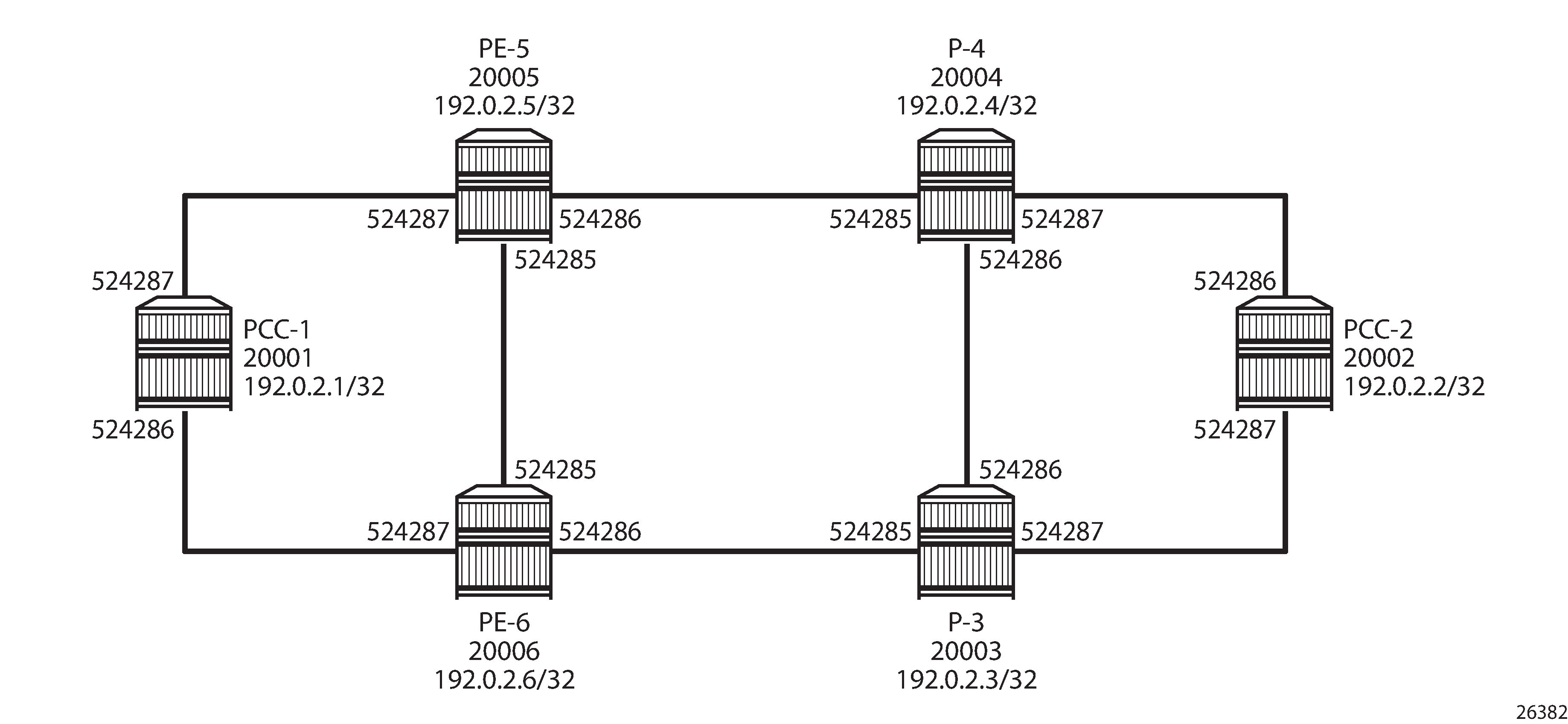
A full collection of SIDs for the whole network is shown in Node and adjacency SIDs.
Segment routing TE-LSPs
This section describes SR-TE LSPs that are configured on the head-end router (the PCC). The path taken through the network is computed locally by the PCC. To influence the path taken, a series of strict and/or loose hops are configured in an MPLS path.
SR-TE LSPs configured with a loose path that contains no hops is effectively a shortest path tunnel to the destination node. The destination address is resolved to the node SID of the tail-end router.
PCC-initiated and computed LSP – strict path
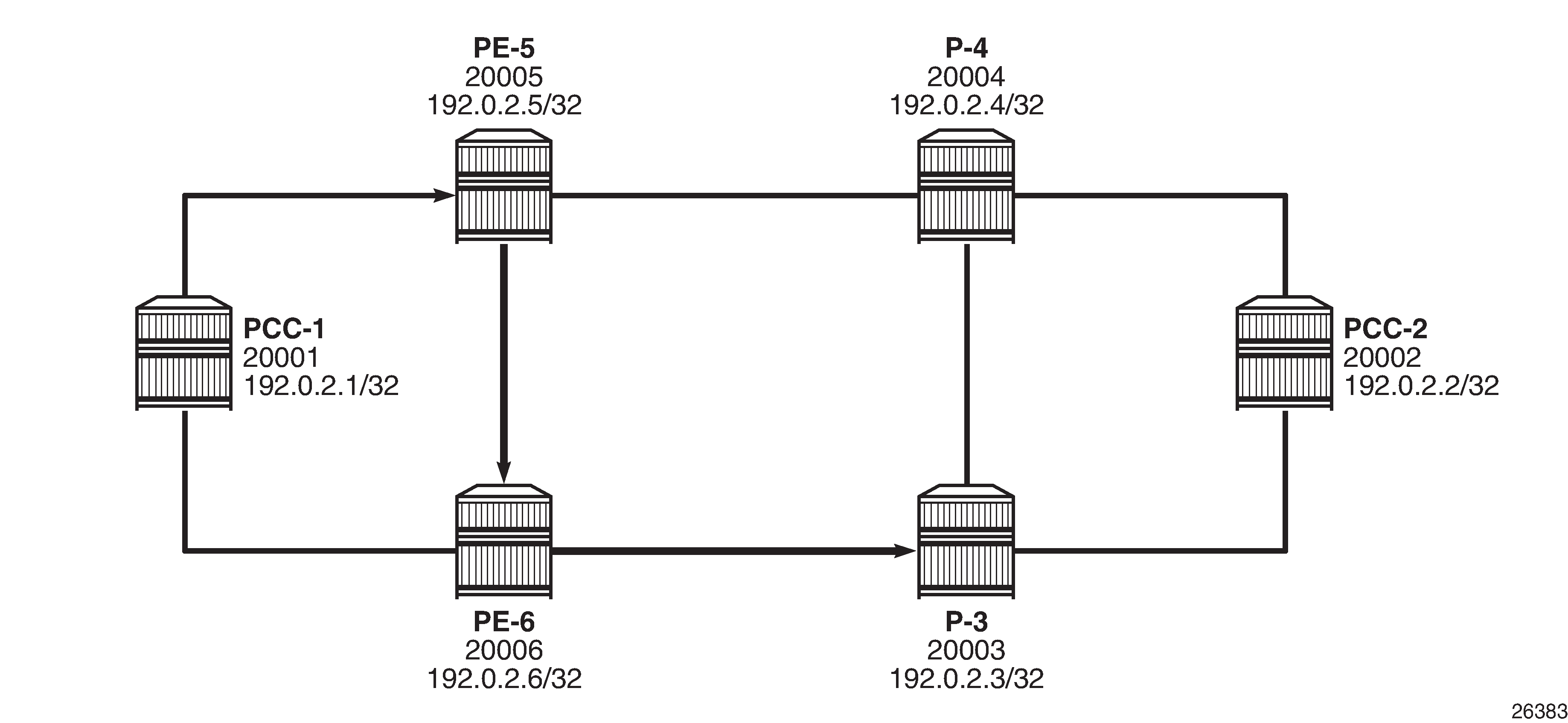
Consider an SR-TE LSP configured on PCC-1, with tail end at PCC-2. Assume there is a requirement for the LSP to avoid the link from PE-5 to P-4 during normal working, so a strict path from PCC-1 via PE-5 to PE-6, and then on to P-3 is required before being forwarded to PCC-2. This is shown in PCC computed strict path between PCC-1 and PCC-2.
To meet these requirements, an MPLS path is configured containing the following strict hops, using the system addresses to identify the hops. The following configures the MPLS path required on PCC-1. This uses the identical CLI construct as an MPLS path used in configuring an RSVP-TE LSP.
# on PCC-1:
configure
    router Base
        mpls
            path "PCC-controlled-strict-path"
                hop 1 192.0.2.5 strict
                hop 2 192.0.2.6 strict
                hop 3 192.0.2.3 strict
                no shutdown
            exit
The SR-TE LSP is configured on PCC-1 as follows:
# on PCC-1:
configure
    router Base
        mpls
            lsp "PCC-1-PCC-2-PCC-strict-lsp" sr-te
                to 192.0.2.2
                primary "PCC-controlled-strict-path"
                exit
                no shutdown
            exit
Again, the same CLI construct as an RSVP-TE LSP is used, except for the sr-te keyword at creation time. If the sr-te keyword is not used, the LSP is signaled as an RSVP-TE LSP. The LSP configuration references the previously-created MPLS path as the primary path.
When placed in a no shutdown state, the LSP path status is as shown in the following output:
*A:PCC-1# show router mpls sr-te-lsp "PCC-1-PCC-2-PCC-strict-lsp" path detail

===============================================================================
MPLS SR-TE LSP PCC-1-PCC-2-PCC-strict-lsp
Path  (Detail)
===============================================================================
Legend :
S      - Strict                      L      - Loose
A-SID  - Adjacency SID               N-SID  - Node SID
    +      - Inherited
===============================================================================
-------------------------------------------------------------------------------
LSP SR-TE PCC-1-PCC-2-PCC-strict-lsp
Path  PCC-controlled-strict-path
-------------------------------------------------------------------------------
LSP Name    : PCC-1-PCC-2-PCC-strict-lsp
Path LSP ID      : 43520
From             : 192.0.2.1
To               : 192.0.2.2
Admin State      : Up                      Oper State        : Up
Path Name   : PCC-controlled-strict-path
Path Type        : Primary
Path Admin       : Up                      Path Oper         : Up
Path Up Time     : 0d 00:00:10             Path Down Time    : 0d 00:00:00
Retry Limit      : 0                       Retry Timer       : 30 sec
Retry Attempt    : 0                       Next Retry In     : 0 sec

PathCompMethod   : none                    OperPathCompMethod: none
MetricType       : igp                     Oper MetricType   : igp
LocalSrProt      : preferred               Oper LocalSrProt  : N/A
LabelStackRed    : Disabled                Oper LabelStackRed: N/A

Bandwidth        : No Reservation          Oper Bandwidth    : 0 Mbps
Hop Limit        : 255                     Oper HopLimit     : 255
Setup Priority   : 7                       Oper SetupPriority: 7
Hold Priority    : 0                       Oper HoldPriority : 0
Inter-area       : N/A

PCE Updt ID      : 0                       PCE Updt State    : None
PCE Upd Fail Code: noError

PCE Report       : Disabled+               Oper PCE Report   : Disabled
PCE Control      : Disabled                Oper PCE Control  : Disabled

Include Groups   :                         Oper IncludeGroups:
None                                           None
Exclude Groups   :                         Oper ExcludeGroups:
None                                           None
Last Resignal    : n/a

IGP/TE Metric    : 16777215                Oper Metric       : 16777215
Oper MTU         : 1548                    Path Trans        : 1
Failure Code     : noError
Failure Node     : n/a
Explicit Hops    :
                  192.0.2.5(S)
               -> 192.0.2.6(S)
               -> 192.0.2.3(S)
Actual Hops      :
    192.168.15.2(192.0.2.5)(A-SID)               Record Label        : 524287
 -> 192.168.56.2(192.0.2.6)(A-SID)               Record Label        : 524285
 -> 192.168.36.1(192.0.2.3)(A-SID)               Record Label        : 524286
 -> 192.0.2.2(192.0.2.2)(N-SID)                  Record Label        : 20002

BFD Configuration and State
Template         : None                    Ping Interval     : N/A
Enable           : False                   State             : notApplicable
WaitForUpTimer   : 4 sec                   OperWaitForUpTimer: 0 sec
WaitForUpTmLeft  : 0
StartFail Rsn    : N/A

===============================================================================
The Actual Hops output shows the address of the upstream router facing the configured strict hop (in brackets) referenced in the MPLS path, plus a loose hop for the destination hop of 192.0.2.2.
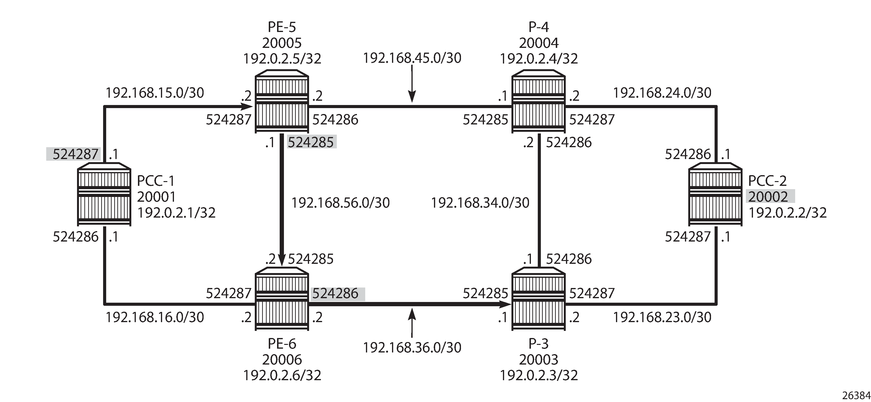
The interface addresses are translated into SIDs to be used as MPLS labels, by the head-end PCC router, PCC-1, by examining the OSPF TE database. Each strict hop is always translated into an adjacency SID (A-SID), and a loose hop is always translated into a node SID (N-SID). This is shown in PCC computed LSP hop-to-label translation.
When the LSP is connected, the Tunnel Table Manager (TTM) adds an entry for the SR-TE LSP. This LSP is available for the provisioning of services that use the TTM. The following output shows the tunnel table for PCC-1, which includes the shortest-path tunnels to all other routers in the network, plus the entry for the provisioned SR-TE LSP. The default preference for an SR-TE LSP in the tunnel table is 8.
*A:PCC-1# show router tunnel-table

===============================================================================
IPv4 Tunnel Table (Router: Base)
===============================================================================
Destination           Owner     Encap TunnelId  Pref   Nexthop        Metric
   Color
-------------------------------------------------------------------------------
192.0.2.2/32          sr-te     MPLS  655362    8      192.168.15.2   16777215
192.0.2.2/32          ospf (0)  MPLS  524291    10     192.168.15.2   2100
192.0.2.3/32          ospf (0)  MPLS  524294    10     192.168.16.2   1100
192.0.2.4/32          ospf (0)  MPLS  524292    10     192.168.15.2   1100
192.0.2.5/32          ospf (0)  MPLS  524293    10     192.168.15.2   1000
192.0.2.6/32          ospf (0)  MPLS  524295    10     192.168.16.2   1000
192.168.15.2/32       ospf (0)  MPLS  524289    10     192.168.15.2   0
192.168.16.2/32       ospf (0)  MPLS  524290    10     192.168.16.2   0
-------------------------------------------------------------------------------
Flags: B = BGP or MPLS backup hop available
       L = Loop-Free Alternate (LFA) hop available
       E = Inactive best-external BGP route
       k = RIB-API or Forwarding Policy backup hop
===============================================================================
The value of the metric is set to 16777215 (infinity – 1), because there is no CSPF and the head-end router is unaware of the full topology between head- and tail-end router.
PCC-initiated and computed LSP – loose path
Consider an LSP configured on PCC-2, with the tail end at PCC-1. There is a requirement for traffic on the LSP to pass through PE-6 before reaching PCC-1, so a loose path of PCC-2 to PE-6 before being forwarded to PCC-1 is required.
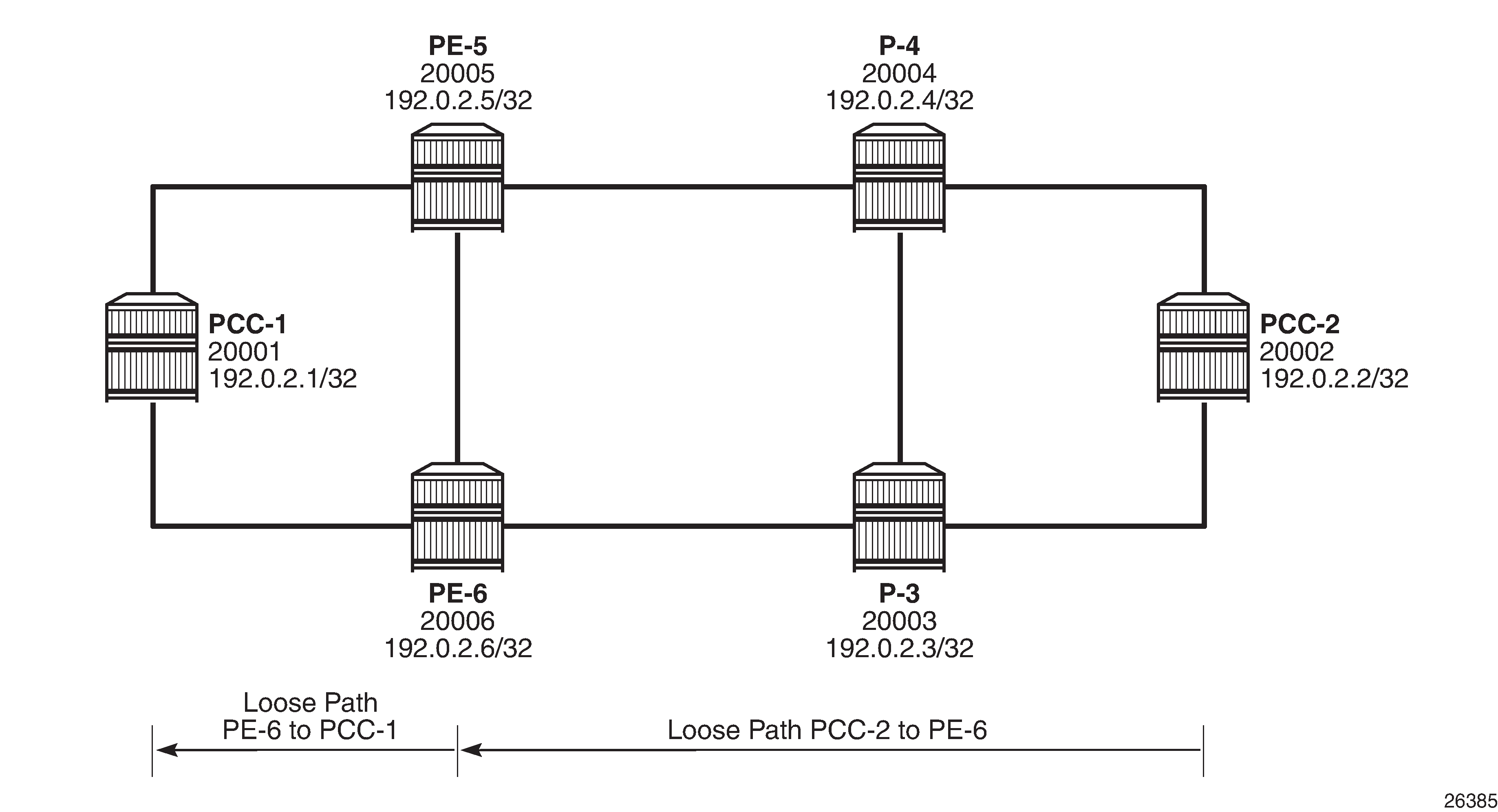
SR-TE LSP with loose path shows the concept of the loose path. The following configures the MPLS path containing a loose hop on PCC-2:
# on PCC-2:
configure
    router Base
        mpls
            path "PCC-controlled-loose-path"
                hop 1 192.0.2.6 loose
                no shutdown
            exit
The SR-TE LSP configuration, which references the previously created MPLS path as the primary path, is as follows:
# on PCC-2:
configure
    router Base
        mpls
            lsp "PCC-2-PCC-1-PCC-loose-lsp" sr-te
                to 192.0.2.1
                primary "PCC-controlled-loose-path"
                exit
                no shutdown
            exit
When placed in a no shutdown state, the LSP path status becomes operationally up, as in the following output:
*A:PCC-2# show router mpls sr-te-lsp "PCC-2-PCC-1-PCC-loose-lsp" path detail

===============================================================================
MPLS SR-TE LSP PCC-2-PCC-1-PCC-loose-lsp
Path  (Detail)
===============================================================================
Legend :
    S      - Strict                      L      - Loose
A-SID  - Adjacency SID               N-SID  - Node SID
    +      - Inherited
===============================================================================
-------------------------------------------------------------------------------
LSP SR-TE PCC-2-PCC-1-PCC-loose-lsp
Path  PCC-controlled-loose-path
-------------------------------------------------------------------------------
LSP Name    : PCC-2-PCC-1-PCC-loose-lsp
Path LSP ID      : 512
From             : 192.0.2.2
To               : 192.0.2.1
Admin State      : Up                      Oper State        : Up
Path Name   : PCC-controlled-loose-path
Path Type        : Primary
Path Admin       : Up                      Path Oper         : Up
Path Up Time     : 0d 00:00:10             Path Down Time    : 0d 00:00:00
Retry Limit      : 0                       Retry Timer       : 30 sec
Retry Attempt    : 0                       Next Retry In     : 0 sec

PathCompMethod   : none                    OperPathCompMethod: none
MetricType       : igp                     Oper MetricType   : igp
LocalSrProt      : preferred               Oper LocalSrProt  : N/A
LabelStackRed    : Disabled                Oper LabelStackRed: N/A

Bandwidth        : No Reservation          Oper Bandwidth    : 0 Mbps
Hop Limit        : 255                     Oper HopLimit     : 255
Setup Priority   : 7                       Oper SetupPriority: 7
Hold Priority    : 0                       Oper HoldPriority : 0
Inter-area       : N/A

PCE Updt ID      : 0                       PCE Updt State    : None
PCE Upd Fail Code: noError

PCE Report       : Disabled+               Oper PCE Report   : Disabled
PCE Control      : Disabled                Oper PCE Control  : Disabled

Include Groups   :                         Oper IncludeGroups:
None                                           None
Exclude Groups   :                         Oper ExcludeGroups:
None                                           None
Last Resignal    : n/a

IGP/TE Metric    : 16777215                Oper Metric       : 16777215
Oper MTU         : 1556                    Path Trans        : 1
Failure Code     : noError
Failure Node     : n/a
Explicit Hops    :
                  192.0.2.6(L)
Actual Hops      :
    192.0.2.6(192.0.2.6)(N-SID)                  Record Label        : 20006
 -> 192.0.2.1(192.0.2.1)(N-SID)                  Record Label        : 20001

BFD Configuration and State
Template         : None                    Ping Interval     : N/A
Enable           : False                   State             : notApplicable
WaitForUpTimer   : 4 sec                   OperWaitForUpTimer: 0 sec
WaitForUpTmLeft  : 0
StartFail Rsn    : N/A

===============================================================================
The Actual Hops in the MPLS path are the configured loose hop plus a hop for the destination of 192.0.2.1.
Again, the configured hop addresses are translated into labels by the head-end PCC router, PCC-2, by examining the OSPF TE database. The hop-to-label translation always translates a loose hop to a node SID (N-SID).
The LSP is installed by the TTM into the tunnel table, alongside OSPF advertised shortest path tunnels, for use by the TTM users.
*A:PCC-2# show router tunnel-table

===============================================================================
IPv4 Tunnel Table (Router: Base)
===============================================================================
Destination           Owner     Encap TunnelId  Pref   Nexthop        Metric
   Color
-------------------------------------------------------------------------------
192.0.2.1/32          sr-te     MPLS  655362    8      192.0.2.6      16777215
192.0.2.1/32          ospf (0)  MPLS  524291    10     192.168.23.2   2100
192.0.2.3/32          ospf (0)  MPLS  524292    10     192.168.23.2   1000
192.0.2.4/32          ospf (0)  MPLS  524293    10     192.168.24.2   1000
192.0.2.5/32          ospf (0)  MPLS  524294    10     192.168.24.2   1100
192.0.2.6/32          ospf (0)  MPLS  524295    10     192.168.23.2   1100
192.168.23.2/32       ospf (0)  MPLS  524289    10     192.168.23.2   0
192.168.24.2/32       ospf (0)  MPLS  524290    10     192.168.24.2   0
-------------------------------------------------------------------------------
Flags: B = BGP or MPLS backup hop available
       L = Loop-Free Alternate (LFA) hop available
       E = Inactive best-external BGP route
       k = RIB-API or Forwarding Policy backup hop
===============================================================================
Service provisioning – VPRN
SR-TE tunnels are another MPLS tunnel type, and can be used in the context of auto-bind-tunnel for resolving BGP next hops for IPv4 routes within a VPRN.
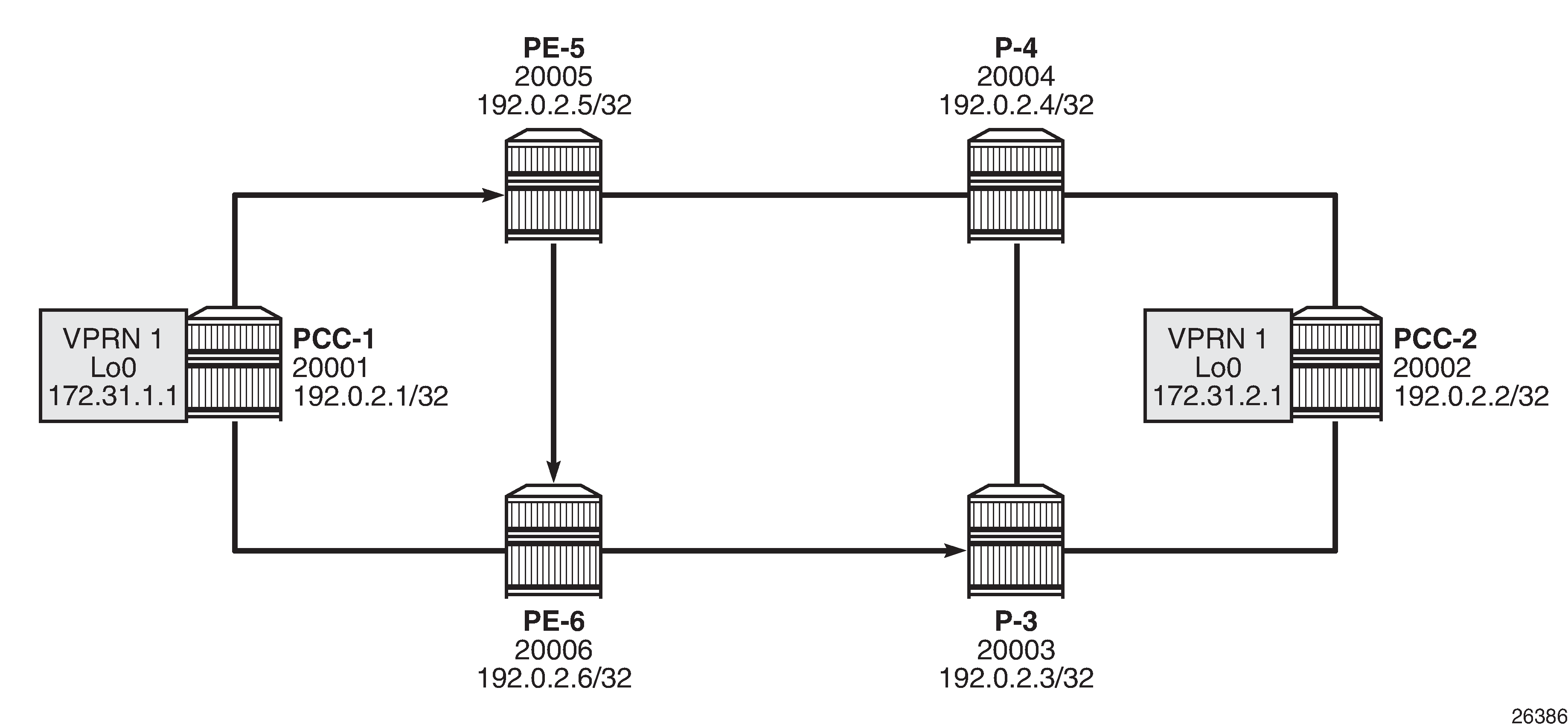
VPRN service schematic shows a VPRN service, configured on PCC-1 and PCC-2. The following configures the VPRN 1 on PCC-1. It includes a local interface using a /32 loopback address, which will be used to verify that routing is working correctly.
# on PCC-1:
configure
    service
        vprn 1 name "VPRN 1" customer 1 create
            autonomous-system 65545
            interface "loopback" create
                address 172.31.1.1/32
                loopback
            exit
            bgp-ipvpn
                mpls
                    auto-bind-tunnel
                        resolution-filter
                            sr-te
                        exit
                        resolution filter
                    exit
                    route-distinguisher 65545:1
                    vrf-target target:65545:1
                    no shutdown
                exit
            exit
            no shutdown
The auto-bind-tunnel command has the resolution-filter option set to sr-te, so that any BGP routes received will have the next-hop resolved to an SR-TE LSP. The VPRN configuration on PCC-2 also uses auto-bind-tunnel sr-te.
# on PCC-2:
configure
    service
        vprn 1 name "VPRN 1" customer 1 create
            autonomous-system 65545
            interface "loopback" create
                address 172.31.2.1/32
                loopback
            exit
            bgp-ipvpn
                mpls
                    auto-bind-tunnel
                        resolution-filter
                            sr-te
                        exit
                        resolution filter
                    exit
                    route-distinguisher 65545:1
                    vrf-target target:65545:1
                    no shutdown
                exit
            exit
            no shutdown
Examination of the VPRN route table shows that the route prefix representing the IP address of the loopback address configured in VPRN 1 is shown, and is resolved via the SR-TE tunnel.
*A:PCC-1# show router 1 route-table

===============================================================================
Route Table (Service: 1)
===============================================================================
Dest Prefix[Flags]                            Type    Proto     Age        Pref
      Next Hop[Interface Name]                                    Metric
-------------------------------------------------------------------------------
172.31.1.1/32                                 Local   Local     00h02m11s  0
       loopback                                                     0
172.31.2.1/32                                 Remote  BGP VPN   00h01m19s  170
       192.0.2.2 (tunneled:SR-TE:655362)                            16777215
-------------------------------------------------------------------------------
No. of Routes: 2
Flags: n = Number of times nexthop is repeated
       B = BGP backup route available
       L = LFA nexthop available
       S = Sticky ECMP requested
===============================================================================
Connectivity is verified by sending a ping from the loopback interface within VPRN 1 on PCC-1 to the loopback address within VPRN 1 on PCC-2, as follows:
*A:PCC-1# ping router 1 172.31.2.1 source 172.31.1.1
PING 172.31.2.1 56 data bytes
64 bytes from 172.31.2.1: icmp_seq=1 ttl=64 time=4.78ms.
64 bytes from 172.31.2.1: icmp_seq=2 ttl=64 time=4.67ms.
64 bytes from 172.31.2.1: icmp_seq=3 ttl=64 time=4.64ms.
64 bytes from 172.31.2.1: icmp_seq=4 ttl=64 time=4.63ms.
64 bytes from 172.31.2.1: icmp_seq=5 ttl=64 time=4.47ms.

---- 172.31.2.1 PING Statistics ----
5 packets transmitted, 5 packets received, 0.00% packet loss
round-trip min = 4.47ms, avg = 4.64ms, max = 4.78ms, stddev = 0.099ms
For completeness, a ping is sent in the opposite direction, between the PCC-2 VPRN 1 interface to PCC-1 VPRN 1, as follows:
*A:PCC-2# ping router 1 172.31.1.1 source 172.31.2.1
PING 172.31.1.1 56 data bytes
64 bytes from 172.31.1.1: icmp_seq=1 ttl=64 time=4.71ms.
64 bytes from 172.31.1.1: icmp_seq=2 ttl=64 time=4.73ms.
64 bytes from 172.31.1.1: icmp_seq=3 ttl=64 time=5.05ms.
64 bytes from 172.31.1.1: icmp_seq=4 ttl=64 time=4.81ms.
64 bytes from 172.31.1.1: icmp_seq=5 ttl=64 time=4.47ms.

---- 172.31.1.1 PING Statistics ----
5 packets transmitted, 5 packets received, 0.00% packet loss
round-trip min = 4.47ms, avg = 4.75ms, max = 5.05ms, stddev = 0.186ms
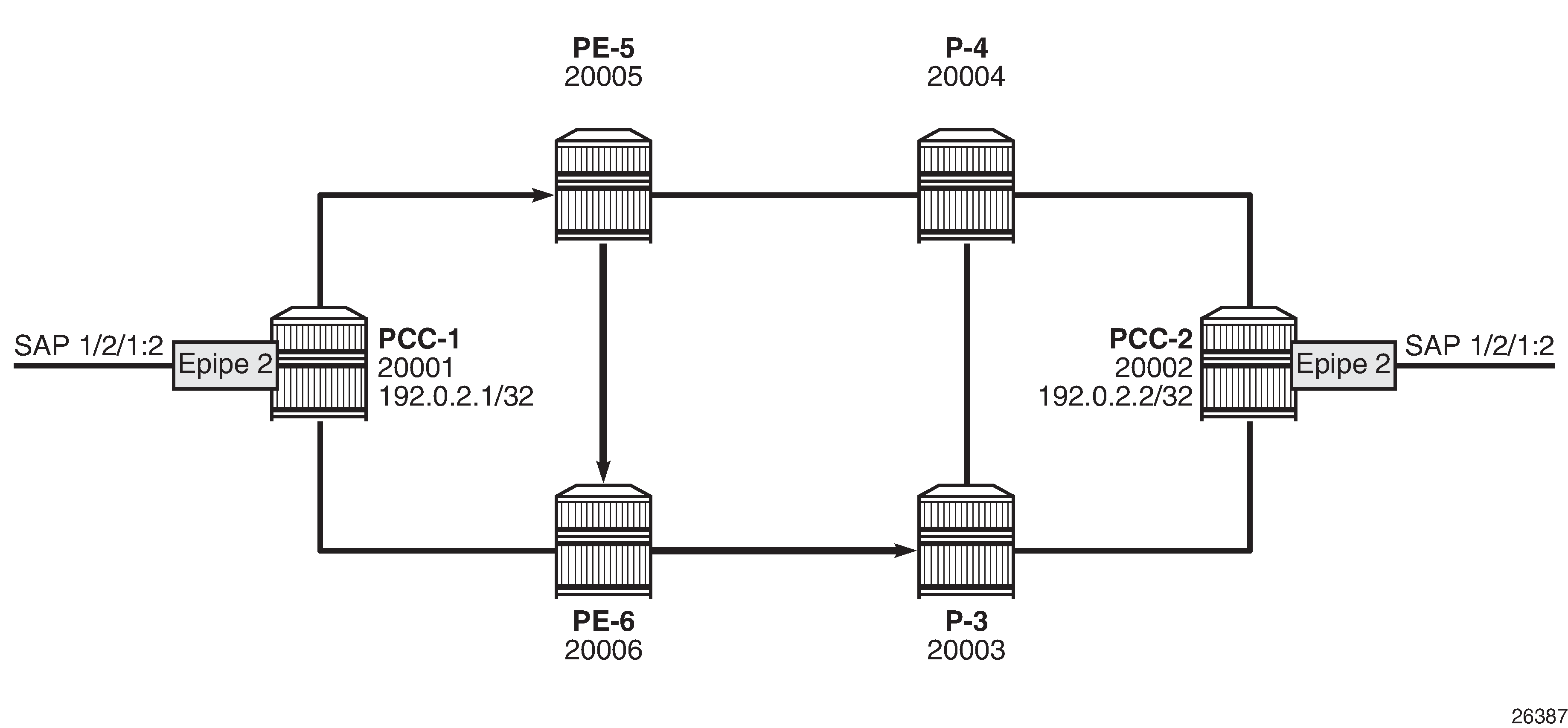
Layer 2 service provisioning – SR-TE
SR-TE tunnels can also be bound as a transport tunnel within SDPs. To illustrate this, consider the following example of a simple Epipe connected between PCC-1 and PCC-2, as shown in Epipe service schematic.
Create an SDP on PCC-1, with far end on PCC-2, and bind it to the previously created SR-TE LSP:
# on PCC-1:
configure
    service
        sdp 12 mpls create
            far-end 192.0.2.2
            sr-te-lsp "PCC-1-PCC-2-PCC-strict-lsp"
            no shutdown
        exit
Create an Epipe on PCC-1:
# on PCC-1:
configure
    service
        epipe 2 name "Epipe 2" customer 1 create
            sap 1/2/1:2 create
            exit
            spoke-sdp 12:2 create
            exit
            no shutdown
        exit
Similarly, for PCC-2, create an MPLS SDP and explicitly bind the SR-TE LSP, as follows:
# on PCC-2:
configure
    service
        sdp 21 mpls create
            far-end 192.0.2.1
            sr-te-lsp "PCC-2-PCC-1-PCC-loose-lsp"
            no shutdown
        exit
Configure Epipe 2 on PCC-2, referencing the SDP as a spoke-SDP:
# on PCC-2:
configure
    service
        epipe 2 name "Epipe 2" customer 1 create
            sap 1/2/1:2 create
            exit
            spoke-sdp 21:2 create
            exit
            no shutdown
        exit
Service verification
The state of SDP 12 on PCC-1 is shown in the following output:
*A:PCC-1# show service sdp

============================================================================
Services: Service Destination Points
============================================================================
SdpId  AdmMTU  OprMTU  Far End          Adm  Opr         Del     LSP   Sig
----------------------------------------------------------------------------
12     0       1544    192.0.2.2        Up   Up          MPLS    T     TLDP
----------------------------------------------------------------------------
Number of SDPs : 1
----------------------------------------------------------------------------
Legend: R = RSVP, L = LDP, B = BGP, M = MPLS-TP, n/a = Not Applicable
        I = SR-ISIS, O = SR-OSPF, T = SR-TE, F = FPE
============================================================================
The output shows the LSP type as an SR-TE LSP - "T".
On PCC-1, the following output shows the base state of the Epipe service entities:
*A:PCC-1# show service id 2 base

===============================================================================
Service Basic Information
===============================================================================
Service Id        : 2                   Vpn Id            : 0
Service Type      : Epipe
MACSec enabled    : no
Name              : Epipe 2
Description       : (Not Specified)
Customer Id       : 1                   Creation Origin   : manual
Last Status Change: 04/08/2021 13:29:11
Last Mgmt Change  : 04/08/2021 13:28:31
Test Service      : No
Admin State       : Up                  Oper State        : Up
MTU               : 1514
Vc Switching      : False
SAP Count         : 1                   SDP Bind Count    : 1
Per Svc Hashing   : Disabled
Vxlan Src Tep Ip  : N/A
Force QTag Fwd    : Disabled
Oper Group        : <none>

-------------------------------------------------------------------------------
Service Access & Destination Points
-------------------------------------------------------------------------------
Identifier                               Type         AdmMTU  OprMTU  Adm  Opr
-------------------------------------------------------------------------------
sap:1/2/1:2                              q-tag        1518    1518    Up   Up
sdp:12:2 S(192.0.2.2)                    Spok         0       1544    Up   Up
===============================================================================
Similarly, on PCC-2, the status of SDP 21 is as follows:
*A:PCC-2# show service sdp

============================================================================
Services: Service Destination Points
============================================================================
SdpId  AdmMTU  OprMTU  Far End          Adm  Opr         Del     LSP   Sig
----------------------------------------------------------------------------
21     0       1552    192.0.2.1        Up   Up          MPLS    T     TLDP
----------------------------------------------------------------------------
Number of SDPs : 1
----------------------------------------------------------------------------
Legend: R = RSVP, L = LDP, B = BGP, M = MPLS-TP, n/a = Not Applicable
        I = SR-ISIS, O = SR-OSPF, T = SR-TE, F = FPE
============================================================================
The state of the Epipe service on PCC-2 is shown in the following output:
*A:PCC-2# show service id 2 base

===============================================================================
Service Basic Information
===============================================================================
Service Id        : 2                   Vpn Id            : 0
Service Type      : Epipe
MACSec enabled    : no
Name              : Epipe 2
Description       : (Not Specified)
Customer Id       : 1                   Creation Origin   : manual
Last Status Change: 04/08/2021 13:29:11
Last Mgmt Change  : 04/08/2021 13:28:58
Test Service      : No
Admin State       : Up                  Oper State        : Up
MTU               : 1514
Vc Switching      : False
SAP Count         : 1                   SDP Bind Count    : 1
Per Svc Hashing   : Disabled
Vxlan Src Tep Ip  : N/A
Force QTag Fwd    : Disabled
Oper Group        : <none>

-------------------------------------------------------------------------------
Service Access & Destination Points
-------------------------------------------------------------------------------
Identifier                               Type         AdmMTU  OprMTU  Adm  Opr
-------------------------------------------------------------------------------
sap:1/2/1:2                              q-tag        1518    1518    Up   Up
sdp:21:2 S(192.0.2.1)                    Spok         0       1552    Up   Up
===============================================================================
Conclusion
Segment routing LSPs extend the use of MPLS labels into traffic engineering applications. This chapter provides the configuration for router instantiated and controlled SR-TE LSPs along with some examples of the application in a VPRN and Epipe. The chapter also shows the associated commands and outputs that can be used for verifying and troubleshooting.