Segment Routing over IPv6
This chapter provides information about Segment Routing over IPv6.
Topics in this chapter include:
Applicability
The information and configuration in this chapter are based on SR OS Release 21.10.R1. Segment Routing over IPv6 (SRv6) is supported on FP4-based equipment in SR OS Release 21.5.R2 and later.
Overview
Segment Routing (SR) provides control over the forwarding paths without any need for path signaling, as described in chapter Segment Routing with IS-IS Control Plane for SR over IPv4. An SR tunnel contains a list of one or more segments. Each segment is identified by a segment identifier (SID). For SR over IPv4, the SIDs are MPLS labels from a configured SR-label range.
SRv6 provides IPv6 transport with both shortest path and source routing capabilities. SRv6 is a framework for the programmability of IPv6, which utilizes the large IPv6 address space. SRv6 data path encapsulation models each SID using a 128-bit IPv6 address, with differences for shortest-path routing and source routing.
In shortest-path routing, the destination SID is encoded in the Destination Address (DA) field of the outer IPv6 header, as shown in SRv6 shortest path routing .
Header type |
Parameter encoding |
|---|---|
IPv6 |
Next header = IP SA = 2001:db8::2:1 DA= 2001:db8:aaaa:101:0:1000:: |
IP |
Version 4, IHL=20 SA= 10.1.2.1 DA = 10.3.2.1 Protocol = UDP ... |
In source routing, the SIDs of the nodes the packet must traverse are encoded as a SID list in the Segment Routing Header (SRH). The next SID in a segment list to forward the packet to is copied from the SRH into the DA field of the outer IPv6 header. The SID in the DA field determines the termination of the current segment. At the segment endpoint node, the next header (in this case, SRH) is examined and the next active SID is copied to the DA field. SRv6 source routing shows an example with SRv6 source routed path segment list in the SRH.
Header type |
Parameter encoding |
|---|---|
IPv6 |
Next header = SRH SA = 2001:db8::2:1 DA= 2001:db8:aaaa:111:0:1000:: |
SRH |
Segments left = 2 Segment 0 - 2001:db8:aaaa:102:0:1000:: Segment 1 - 2001:db8:aaaa:112:0:1000:: Segment 2 - 2001:db8:aaaa:111:0:1000:: Next Header = IP |
SRv6 SID
An SRv6 SID is a routable IPv6 prefix when it is set as the IPv6 header DA.
IPv6 router interface addresses are not SRv6 SIDs.
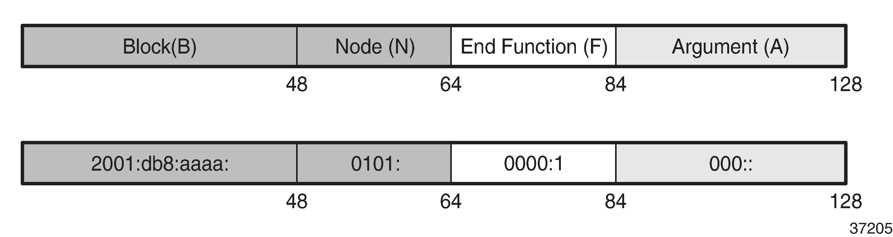
SRv6 SID encoding shows that the 128-bit address of an SRv6 SID is split into three constituent parts: locator, function, argument.
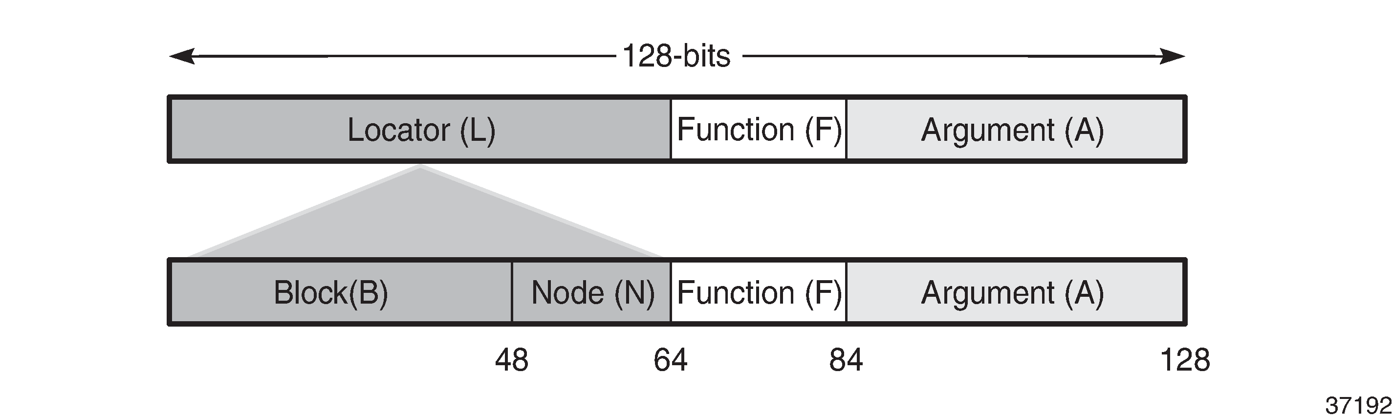
The locator is a summary IPv6 prefix for a set of SIDs instantiated on an SRv6-capable router. The locator:
must be explicitly configured
is advertised using IS-IS
can be associated with a topology and/or Flex-Algorithm
provides reachability to all SIDs originated by a router if the locator part of the SRv6 SID is routable
comprises the L most significant bits of the SID, with L ranging from 4 to 96 bits
has format B:N
All routers in a domain have the same block address B.
Each router in the domain has its own node-specific address N.
The function is an opaque identification of a local behavior bound to the segment, as described in RFC 8986. SRv6 endpoint behaviors supported in SR OS Release 21.10.R1 lists the SRv6 endpoint behaviors supported in SR OS Release 21.10.R1.
Table 3. SRv6 endpoint behaviors supported in SR OS Release 21.10.R1 Function name
Role or behavior
Description
End
Endpoint
Equivalent to a node SID
End.X
Endpoint with an L3 cross-connect (X-connect)
Equivalent to an adjacency SID
LAN-End.X
Endpoint with an L3 cross-connect (X-connect)
Equivalent to an adjacency SID associated with a broadcast interface
End.DT4
De-encapsulate and perform an IPv4 table lookup
VPRN table lookup: per-VRF SID for the VPN-IPv4 address family
Prefix lookup in the global IPv4 routing table
End.DT6
De-encapsulate and perform an IPv6 table lookup
VPRN table lookup: per-VRF SID for the VPN-IPv6 address family
Prefix lookup in the global IPv6 routing table
End.DT46
De-encapsulate and perform IPv4 and IPv6 table lookups
VPRN table lookup: both IPv4 and IPv6 - equivalent to per-VRF label
VPN-IPv4 and VPN-IPv6 routes are advertised with a single label in the same VRF
The argument, which is not a configurable field in SR OS Release 21.10.R1, is set to all zeros.
SRv6 SID encoding example shows an example of an SRv6 SID with the following:
B = 48 bits
N = 16 bits
L = B + N = 48 bits + 16 bits = 64 bits
F = 20 bits
The remaining 44 bits (A) are set to zero.
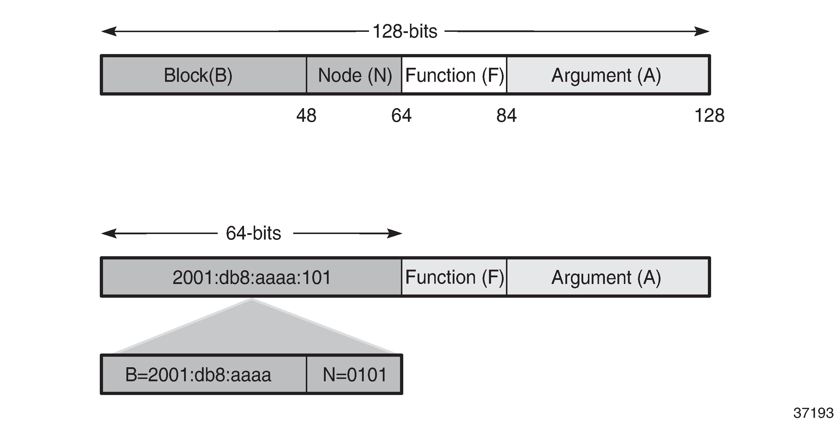
The /64 locator part for a set of routers in a routing domain consists of:
a common 48-bit block, for example, 2001:db8:aaaa::/48
a unique 16-bit node identifier allocated in the range from 0000 to ffff
Some examples:
locator for PE-1 = 2001:db8:aaaa:101::/64
locator for PE-2 = 2001:db8:aaaa:102::/64
locator for PE-3 = 2001:db8:aaaa:103::/64
The local router installs the locator in its IPv6 route table and FIB. The locator prefix is advertised in IS-IS in the SRv6 locator sub-TLV. Each remote router populates its route table and FIB with the locator prefixes, including the tunneled next-hop to the originating router.
The function field has a configurable length, ranging from 20 to 96 bits. By default, the function field has 20 bits. The function field is used to assign End and End.X SIDs, which are used by remote routers to create repair tunnels for remote and topology-independent loopfree-alternate (RLFA and TI-LFA) backup paths.
An End function is statically configured in SR OS:
By default, the number of static functions is 1.
For example, the End function with value 1 in the 20-bit format is represented as 00001 in hexadecimal, followed by the zeros of the argument field.
The End SID (node SID) for PE-1 equals 2001:db8:aaaa:101:0:1000::/128, as shown in End SID for PE-1
Figure 3. End SID for PE-1 
The End.X function can be statically configured or automatically assigned by the system.
In case of static configuration, the number of static functions must be increased.
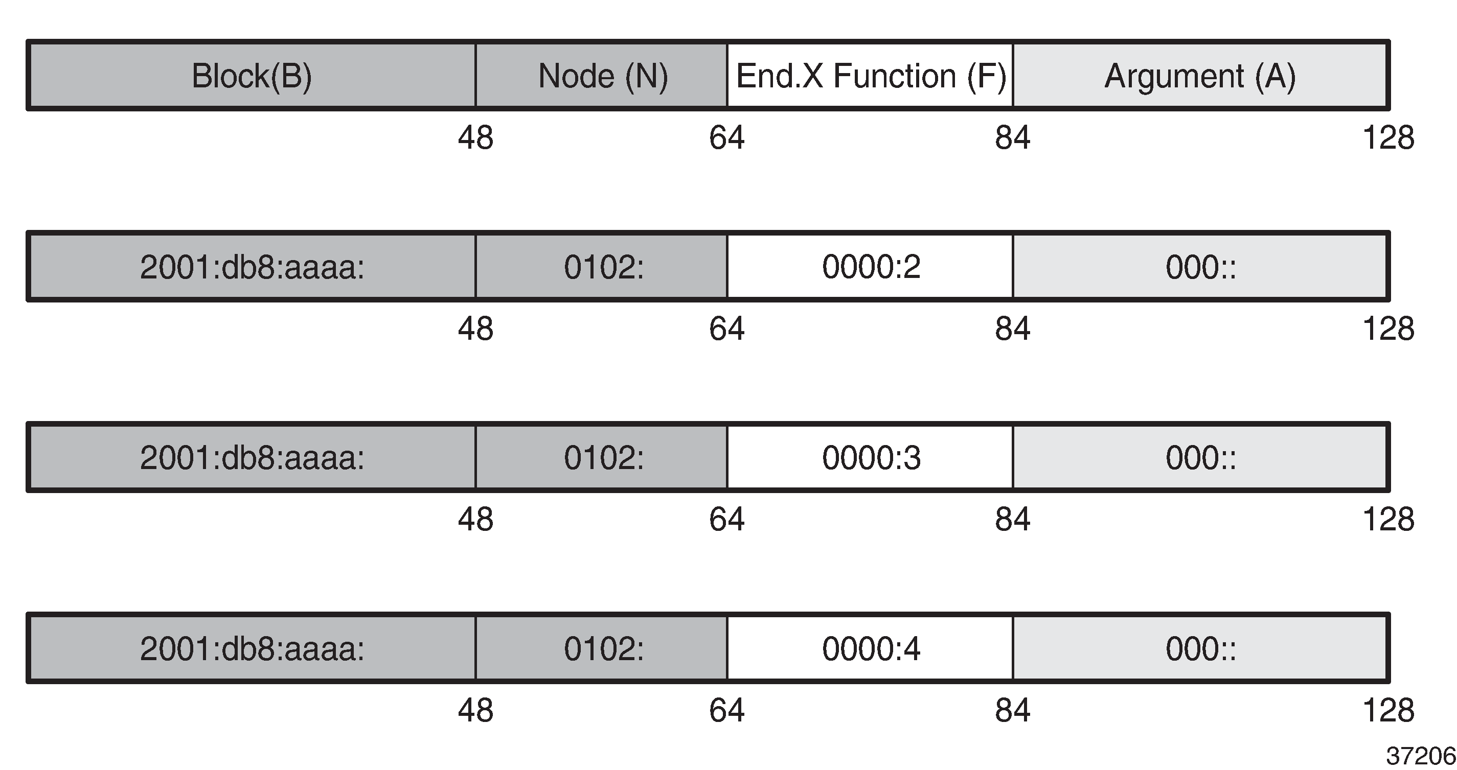
For the function with value 2 in a function field of 20 bits, the corresponding hexadecimal pattern is 00002, followed by the zeros of the argument field.
The End.X SID (adjacency SID) for PE-1 equals 2001:db8:aaaa:101:0:2000::/128, as shown in End.X SID for PE-1.
Figure 4. End.X SID for PE-1 
IPv6 header and SRH
This section describes how source routing works with the insertion of an SRH.
SR OS Release 21.10 has no mechanism for computing a source-routed path for normal data traffic flow; for example, there is no equivalent to the SR-TE or SR-policy label stack for source routing. The use of the SRH is restricted to repair tunnels computed by the TI-LFA process. When a link or node failure occurs, the Point of Local Repair (PLR) inserts an appropriate SRH for SRv6 traffic that is to be routed around the failure during IGP convergence.
Different SR node types are defined: source node, transit node, and segment endpoint node. To enable source routing on the IPv6 source router, the SRH contains an ordered list of one or more SRv6 SIDs.
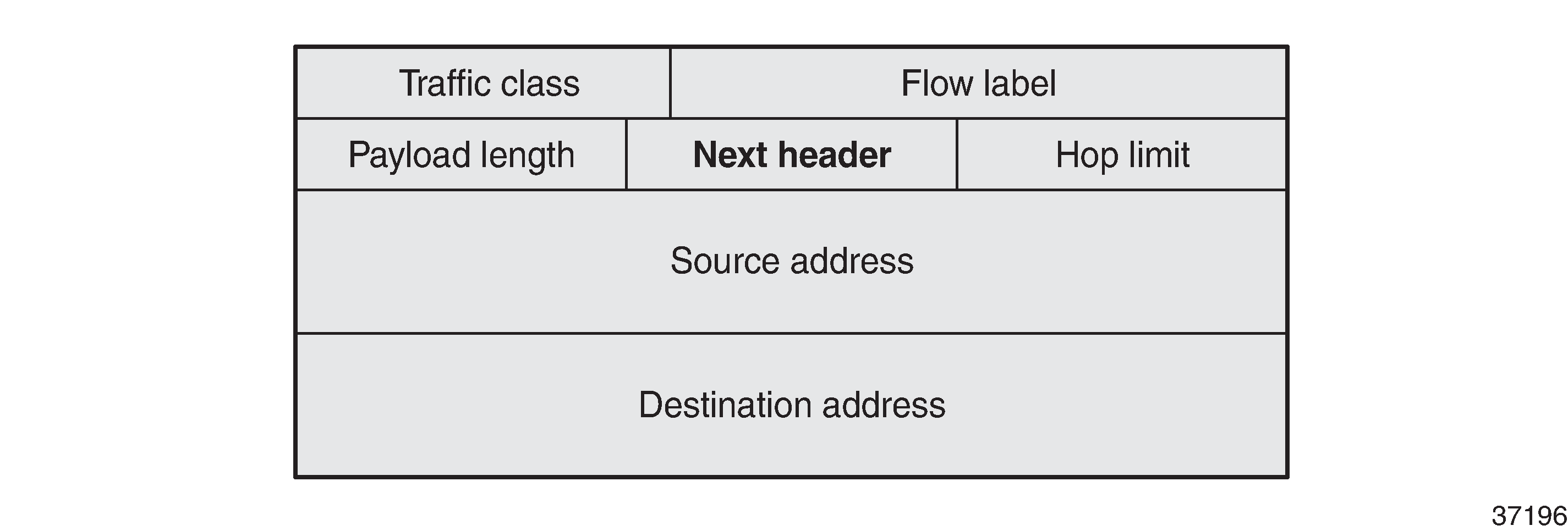
IPv6 header defined in RFC 8200 shows the IPv6 header where the next header field must be coded as 43 when the IPv6 extension header, which follows the IPv6 header, is an SRH.
Position of the SRH in the protocol stack shows that the header following the IPv6 header sits between the IPv6 header and upper layer protocols, such as TCP or UDP.

SRH defined in RFC 8754 shows the SRH.
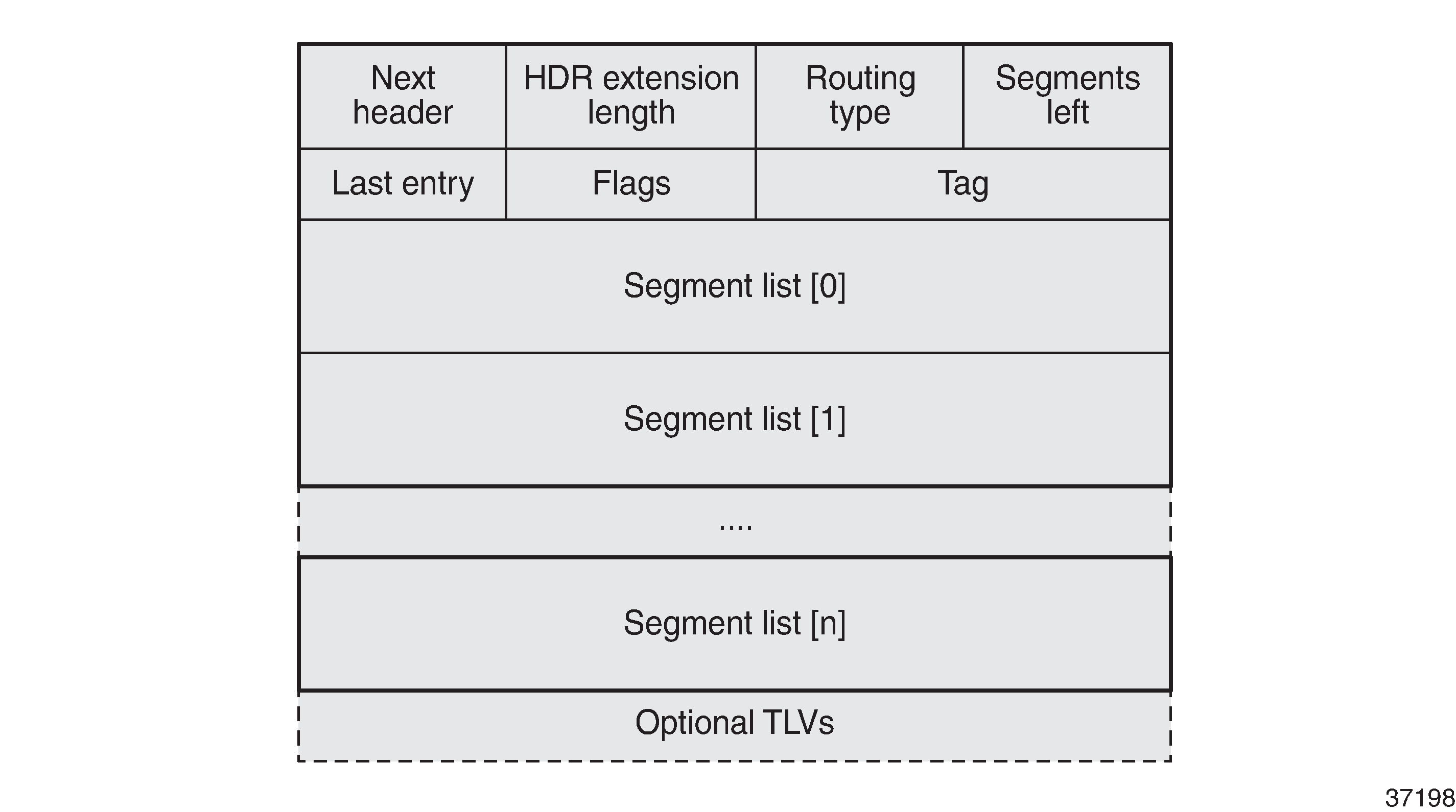
The SRH is derived from the IPv6 routing header as defined in RFC 8200. The SRH fields are:
Next header: defines the type of header following SRH, for example, TCP or UDP.
Routing type for SRH: 4.
Segments left: the number of explicitly listed intermediate nodes still to be traversed before reaching the final destination.
Last entry: contains the zero-based index of the last element of the segment list.
Segment list [n]: a 128-bit IPv6 address representing the nth segment in the segment list. The segment list is encoded in reverse numerical order: segment list [0] is the first element in the segment list and contains the last segment of the SR path, segment list [1] contains the penultimate segment of the SR path, and so on.
SRv6 node types shows the SR node types: source node, transit node, and segment endpoint node for an SRv6 packet flow from R0 to R5 via hops R1, R3, and R5.
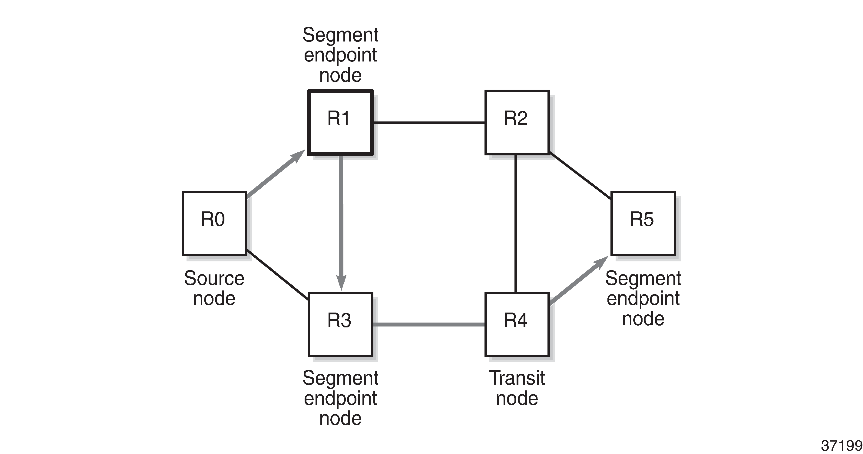
The intermediate hops R1, R3, and R5 are programmed in the segment list of the SRH.
The SRv6 node types defined in RFC 8754 are:
SR source node
Any node that originates an IPv6 packet with a segment (that is, an SRv6 SID) in the DA field of the IPv6 header.
The IPv6 packet leaving the SR source node may or may not contain an SRH. This includes either:
a host originating an IPv6 packet
an SR domain ingress router encapsulating a received packet in an outer IPv6 header, followed by an optional SRH
In this example, R0 acts as an SR source node and includes an SRH containing a segment list.
SR transit node
Any node forwarding an IPv6 packet where the DA of the packet is not locally configured as a segment or a local interface. A transit node need not be capable of processing a segment or SRH.
In this example, R4 acts as an SR transit node. It forwards the SRv6 packet without processing the SRH.
SR segment endpoint node
Any node receiving an IPv6 packet where the DA of that packet is locally configured as a segment or local interface.
In this example, R1, R3, and R5 are SR segment endpoint nodes. These nodes interrogate the SRH as part of packet processing.
Data forwarding of SRv6 encapsulated packets using SRv6 SIDs shows the data forwarding of SRv6 encapsulated packets using SRv6 SIDs at R0 and R1.
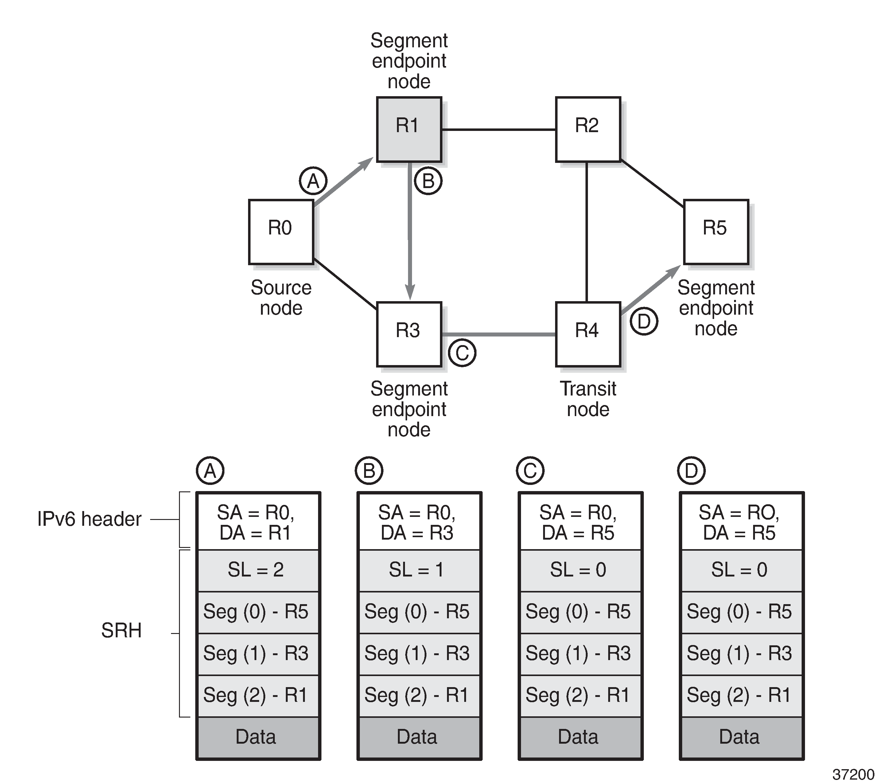
Source node R0 tunnels an SRv6 packet to destination R5, segment (0), in the SRH.
The segment list contains SRv6 SIDs associated with each hop, such as the End SID. The first segment endpoint is the last segment in the list, segment (2) in the example. The Segments Left (SL) field is set to a value matching the highest segment list number (2).
SRH is only used by routers where the DA is equal to a local address. The IPv6 source address is set to the local IPv6 address of R0. The IPv6 DA in the IPv6 header is set to the segment list entry indexed in the SL field; in this case, R1.
The packet is forwarded to R1.
At R1, the incoming packet has the IPv6 DA matching R1.
R1 removes the IPv6 header and processes the SRH. The SL is decremented to SL 1, which corresponds to segment (1) = R3.
R1 adds an IPv6 header with DA equal to the SID for R3.
R1 forwards the packet to R3.
At R3, the incoming packet has the IPv6 DA matching R3.
R3 removes the IPv6 header and processes the SRH. The SL is decremented to SL 0, which corresponds to segment (0) = R5.
R3 adds an IPv6 header with DA equal to the SID for R5.
R3 forwards the packet to R5.
At R4, the incoming packet has the IPv6 DA matching R5, so the packet is forwarded to R5 without processing the SRH header and without changing the IPv6 DA.
At R5, the incoming packet has the IPv6 DA matching R5, so the IPv6 header is removed and the SRH header is processed. The SL value 0 cannot be decreased anymore, so R5 removes the SRH and the packet is sent for further processing, for example, to a particular VPRN.
The IPv6 SID at segment (0) may contain an opaque behavior value (function) that indicates to the destination node that further processing is required, such as a VPRN table lookup.
Data path support: forwarding path extensions
SRv6 data traffic requires additional processing at both the ingress and egress data planes. This processing is performed via an internal cross connect in the form of port cross-connect (PXC) ports. SRv6 traffic is steered from the input to a PXC port, where it is internally looped for additional processing.
The PXC port is associated with the SRv6 application using a Forwarding Path Extension (FPE). An origination (egress) FPE and termination (ingress) FPE are associated with SRv6. The additional processing in the SRv6 data path is as follows:
Ingress PE node
At the origination FPE data path, L2 and L3 service packets are received and the SRv6 encapsulation header is pushed for the primary path and for the backup path based on the index passed by the service context in the internal packet header.
The hop-limit field in the outer IPv6 header of the SRv6 tunnel is set to 255.
At the termination FPE data path, a lookup is done on the DA field in the outer IPv6 header, and the packet is forwarded to one of the candidate egress network IP interfaces based on a hash of the flow label and SA/DA fields of the outer IPv6 packet header.
Egress PE node
At the origination FPE data path of the incoming router interface, a longest prefix match of the DA in the outer IPv6 header is performed in the SRv6 SID FIB.
If there is a match against a local locator prefix, the packet is forwarded to the termination FPE for service SID termination processing.
The termination FPE does an Ingress Label Map (ILM) lookup on the service label and forwards the packet to the service context for further processing.
At the origination FPE data path, the SRH is processed. The SRv6 encapsulation is removed, and a service label is inserted into the inner packet with label value derived from the function field.
Transit router
Transit routers do not require FPEs.
Transit routers receiving SRv6-encapsulated packets make forwarding decisions based on the IPv6 route table lookups.
SRH processing modes
SR OS supports two SRH processing modes at the end of the SRv6 tunnel:
Ultimate SRH Pop (USP), where the ultimate SR segment endpoint node processes and removes the SRH
Penultimate SRH Pop (PSP), where the penultimate SR segment endpoint node processes and removes the SRH
USP mode
In the following example, source node PE-2 sends a packet to SR segment endpoint node PE-1 via intermediate hops P-2 and P-1. USP mode - egress router PE-1 processes and removes SRH shows how penultimate SR segment endpoint node P-1 and ultimate SR segment endpoint node PE-1 process the SRH in the packet.
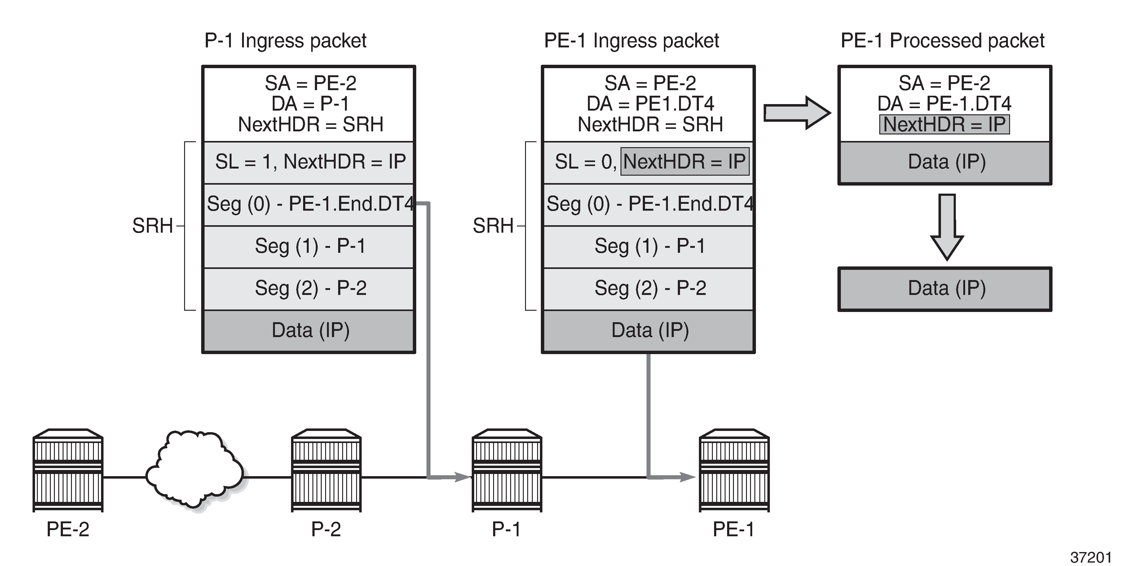
Source node PE-2 sends a packet with SRH with three segments in the segment list: Seg(2) for P-2, Seg(1) for P-1, and Seg(0) for destination PE-1. P-1, P-2, and PE-1 are SR segment endpoint nodes. Penultimate SR segment endpoint node P-1 decrements the value in the SL field in the SRH from 1 to 0 and copies the PE-1 SID from segment 0 into the IPv6 header DA. Ultimate SR segment endpoint node PE-1 receives the packet with the DA equal to PE-1.End.DT4 and SL 0 and processes the packet by:
updating the Next Header field in the IPv6 header with the Next Header field of the SRH
removing the SRH from the IPv6 extension header chain
processing the next header in the packet, which is achieved using the origination FPE data path
In this example, the IPv6 SID at segment (0) "PE-1.End.DT4" contains a function indicating to the destination node that a VPRN table lookup is required.
PSP mode
As stated in RFC 8986, a penultimate SR segment endpoint node is one that, as part of the SID processing, copies the last SID from the SRH into the IPv6 DA and decrements the SL value from one to zero.
Penultimate SRH hop P-2 processes and removes the SRH shows how penultimate SR segment endpoint node P-2 processes the packet toward PE-1. P-1 is an SR transit node in this example, so it does not process an SRH.
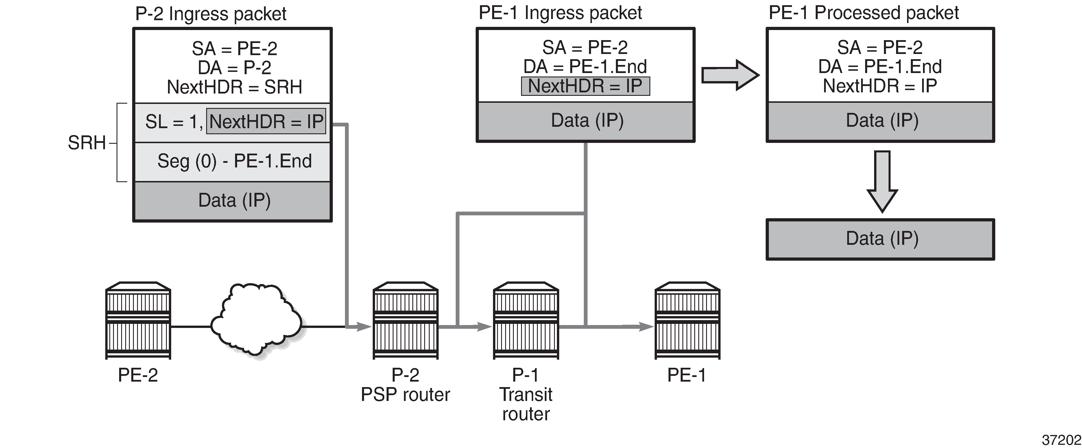
The PSP operation is controlled by the SR source node. SR source node PE-2 is aware that the PE-1.End SID has SRH mode PSP. PE-2 sends a packet to PE-1 with the DA set to P-2 in the IPv6 header. The SRH contains one SID in the segment list: Seg(0) PE-1.End. The SL is set to 1.
Penultimate SR segment endpoint node P-2 processes the packet by:
decrementing the IPv6 hop limit by 1
decrementing the SL by 1, so SL = 0
updating the IPv6 DA with the PE-1.End node SID from the segment list
updating the Next Header field in the IPv6 header to the Next Header field of the SRH
removing the SRH from the IPv6 extension header chain
submitting the packet to the MPLS engine for transmission
At transit node P-1, the packet is forwarded based on the RTM lookup for IPv6 DA in the IPv6 header.
At the destination node PE-1, the IPv6 header is removed and additional processing of the next header in the packet is done via an origination FPE data path.
Configuration
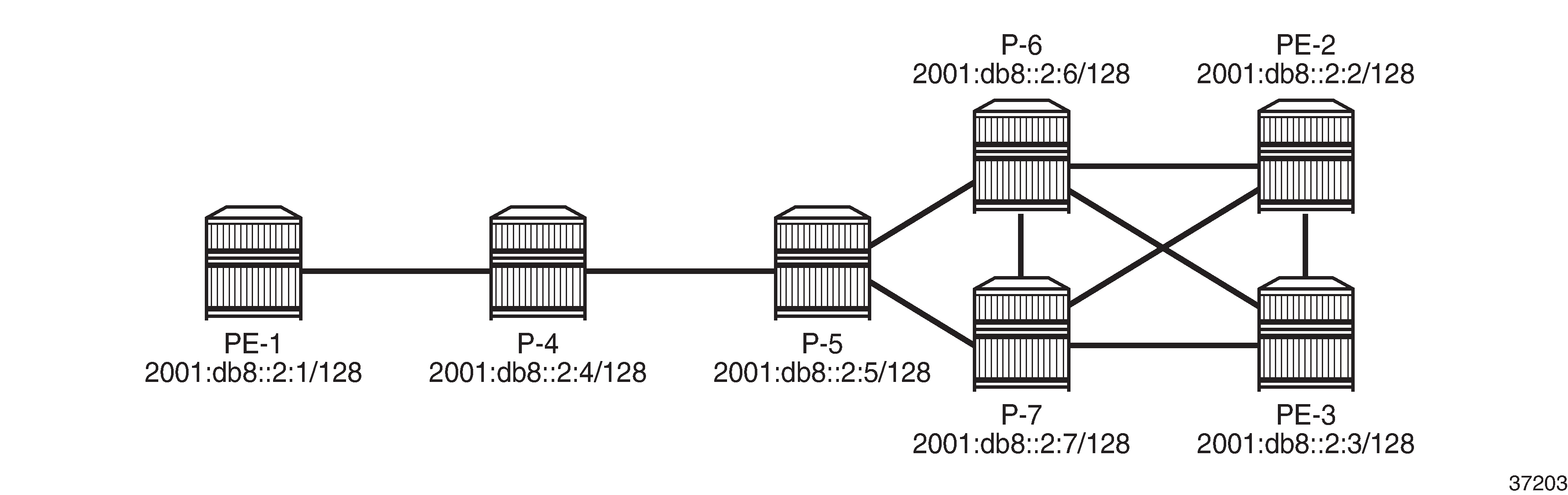
Example topology shows the example topology with seven SRv6-capable routers (with FP4).
PXC
SRv6 traffic is steered from input to a PXC port, where it is internally looped for additional processing. PXC can use either an internally looped physical port or an internal loopback in the FP4 MAC chip.
In case of an internally looped physical port, configure PXC on the physical port, as shown in the following example for PXC 5 on physical port 1/1/c5/1:
# on all SRv6-capable nodes:
configure
    port-xc
        pxc 5 create
            port 1/1/c5/1
            no shutdown
        exit
    exit
    port pxc-5.a
        no shutdown
    exit
    port pxc-5.b
        no shutdown
    exit
    port 1/1/c5/1
        no shutdown
    exit
exit
In case of internal loopbacks in the FP4 MAC chip, map PXC 1 and PXC 2 to internal loopbacks. It is possible to map PXC 1 and PXC 2 to the same loopback on the same MAC chip, but that is not configured here.
# on all SRv6-capable nodes:
configure
    card 1
        mda 1
            xconnect
                mac 1 create
                    loopback 1 create
                    exit
                    loopback 2 create
                    exit
                exit
            exit
            no shutdown
        exit
    exit
    port-xc
        pxc 1 create
            port 1/1/m1/1
            no shutdown
        exit
        pxc 2 create
            port 1/1/m1/2       # or loopback 1/1/m1/1 (same as PXC 1)
            no shutdown
        exit
    exit
    port pxc-1.a
        no shutdown
    exit
    port pxc-1.b
        no shutdown
    exit
    port pxc-2.a
        no shutdown
    exit
    port pxc-2.b
        no shutdown
    exit
    port 1/1/m1/1
        no shutdown
    exit
    port 1/1/m1/2
        no shutdown
    exit
exit
There are several MAC chips per FP4-complex (hardware dependent). The operator configures the location of the loopback. The PXC loopback must be referenced as a port ID to enable loopback. The following show datapath command includes the internal loopbacks 1/1/m1/1 and 1/1/m1/2:
*A:PE-2# show datapath 1 detail

===============================================================================
Card    [XIOM/]MDA  FP  TAP   MAC Chip Num   Connector      Port
-------------------------------------------------------------------------------
1       1           1   1     1              c1             1/1/c1/1
1       1           1   1     1              c1             1/1/c1/2
1       1           1   1     1              c1             1/1/c1/3
1       1           1   1     1              c1             1/1/c1/4
---snip---

1       1           2   1     6              c36            1/1/c36/1
1       1           2   1     6              c36            1/1/c36/2
1       1           2   1     6              c36            1/1/c36/3
1       1           2   1     6              c36            1/1/c36/4
1       1           1   1     1              N/A            1/1/m1/1
1       1           1   1     1              N/A            1/1/m1/2
===============================================================================
In this example, PXC loopbacks are configured on MDA 1/1, which has two MAC chips with MAC chip numbers m1 and m2. The two internal loopbacks are configured on MAC chip number m1.
Nokia recommends selecting cards and MAC chips connected to faceplate ports with lower bandwidth utilization for internal PXCs.
In this example, all nodes can act as SR segment endpoint nodes; there are no SR transit nodes. Perform the following steps to enable SRv6 on the nodes:
Allocate an address block B for all routers in a domain; for example, 2001:db8:aaaa::/48.
Allocate a unique node address N for each router; for example, 0101 for PE-1.
Configure a locator for each router in the format B:N:: and set the prefix length of the locator; for example, /64.
Add FPE to configure the data path.
Configure the End function (the SRv6 equivalent for node SID) for each router locator.
Configure the End.X functions (the SRv6 equivalent for adjacency SIDs) for each router associated with locator.
Advertise the locator in IS-IS level 1 or 2, as required.
Locator B:N::
SRv6 router locator prefixes shows the router locator prefixes for the seven nodes in the sample topology.
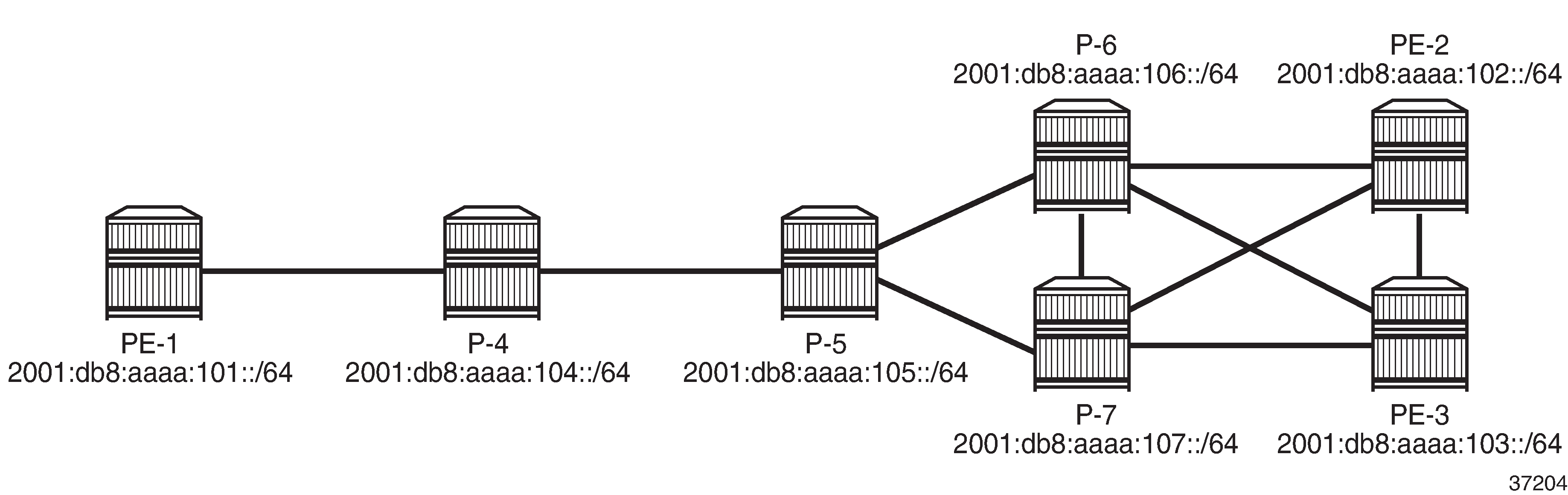
Configure the SRv6 address block B and the locator prefix on the nodes. The following example shows SRv6 address block B 2001:db8:aaaa::/48 and locator prefix 2001:db8:aaaa:101::/64 in the dedicated segment-routing-v6 context on PE-1:
# on PE-1:
configure
    router Base
        segment-routing
            segment-routing-v6
                locator "PE-1_loc"
                    block-length 48
                    prefix
                        ip-prefix 2001:db8:aaaa:101::/64
                    exit
                    no shutdown
                exit
The configuration on the other nodes is similar with the locator prefixes as shown in SRv6 router locator prefixes.
FPE
SRv6 packet processing requires an ingress (termination) FPE and an egress (origination) FPE. FPE 1 is configured as srv6 origination; FPE 2 as srv6 termination. FPE 1 is configured as origination-fpe in the global segment-routing-v6 context; FPE 2 is configured as termination-fpe in the locator context. On PE-1, the configuration is as follows:
# on PE-1:
configure
    fwd-path-ext
        fpe 1 create
            path pxc 1
            srv6 origination
                interface-a
                exit
                interface-b
                exit
            exit
        exit
        fpe 2 create
            path pxc 2
            srv6 termination
                interface-a
                exit
                interface-b
                exit
            exit
        exit
    exit
    router Base
        segment-routing
            segment-routing-v6
                origination-fpe 1
                source-address 2001:db8::2:1
                locator "PE-1_loc"
                    block-length 48
                    termination-fpe 2
                    prefix
                        ip-prefix 2001:db8:aaaa:101::/64
                    exit
                    no shutdown
                exit
            exit
The configuration on the other nodes is similar.
The following command for FPE 1 shows that SRv6 is enabled and operationally up and the SRv6 type is origination:
*A:PE-1# show fwd-path-ext fpe 1

===============================================================================
FPE Id: 1
===============================================================================
Description        : (Not Specified)
Multi-Path         : Disabled
Path               : pxc 1
Pw Port            : Disabled                          Oper     : down
Sub Mgmt Extension : Disabled                          Oper     : N/A
Vxlan Termination  : Disabled                          Oper     : down
Segment-Routing V6 : Enabled                           Oper     : up
SRv6 Type          : origination
If-A Qos Policy    : default
If-B MTU           : 9786 bytes                        Oper MTU : 1556 bytes
If-B Qos Policy    : default
===============================================================================
The following command for FPE 2 shows that SRv6 is enabled and operationally up and the SRv6 type is termination:
*A:PE-1# show fwd-path-ext fpe 2

===============================================================================
FPE Id: 2
===============================================================================
Description        : (Not Specified)
Multi-Path         : Disabled
Path               : pxc 2
Pw Port            : Disabled                          Oper     : down
Sub Mgmt Extension : Disabled                          Oper     : N/A
Vxlan Termination  : Disabled                          Oper     : down
Segment-Routing V6 : Enabled                           Oper     : up
SRv6 Type          : termination
If-A Qos Policy    : default
If-B MTU           : 0 bytes                           Oper MTU : 1556 bytes
If-B Qos Policy    : default
===============================================================================
The following command on PE-1 shows the associations for FPE 1. FPE 1 is an origination FPE, so it is not associated with a locator.
*A:PE-1# show fwd-path-ext associations fpe 1

===============================================================================
Segment-routing V6 associations
===============================================================================
Srv6
-------------------------------------------------------------------------------
Origination-fpe
===============================================================================

===============================================================================
Segment-routing V6 Locator associations
===============================================================================
Locator
-------------------------------------------------------------------------------
===============================================================================
The following command on PE-1 shows the associations for FPE 2. FPE 2 is a termination FPE associated with locator "PE-1_loc".
*A:PE-1# show fwd-path-ext associations fpe 2

===============================================================================
Segment-routing V6 associations
===============================================================================
Srv6
-------------------------------------------------------------------------------
===============================================================================

===============================================================================
Segment-routing V6 Locator associations
===============================================================================
Locator
-------------------------------------------------------------------------------
PE-1_loc
===============================================================================
Functions
End function
The SRv6 End function is configured in the SRv6 End SID that is the equivalent for IPv4 node SIDs. SRv6 End SID on PE-1 shows an example with End function value 1 on PE-1:
The SRv6 End function is statically configured in the segment-routing-v6>base-routing-instance>locator context, as follows:
# on PE-1:
configure
    router Base
        segment-routing
            segment-routing-v6
                locator "PE-1_loc"
                    block-length 48
                    function-length 20          # default
                exit
                base-routing-instance
                    locator "PE-1_loc"
                        function
                            end 1               # function value = 1
                                srh-mode usp
                            exit
                        exit
                    exit
                exit
The configuration on the other nodes is similar.
By default, the function-length is 20. The value function end 1 defines a function value of 1 inserted into the 20-bit function field. The srh-mode determines whether USP or PSP mode is used to process and remove the SRH. The default SRH mode is PSP.
A node can have one or two End functions. If both PSP and USP modes are used, a unique End function can be configured for each SRH mode. This requires the increase of the number static functions allowed, because the default value is 1; static-function max-entries is configured for this purpose. As an example, this is configured on PE-1 only:
# on PE-1:
configure
    router Base
        segment-routing
            segment-routing-v6
                locator "PE-1_loc"
                    static-function
                        max-entries 2           # 2 static functions (end 1, end 2)
                    exit
                exit
                base-routing-instance
                    locator "PE-1_loc"
                        function
                            end 1               # End function value = 1
                                srh-mode usp    # Ultimate SRH Pop
                            exit
                            end 2               # End function value = 2
                                srh-mode psp    # Penultimate SRH Pop (default)
                            exit
                        exit
                    exit
                exit
The following command shows the End SID values for the locators in the base routing instance on PE-1:
*A:PE-1# show router segment-routing-v6 local-sid end

===============================================================================
Segment Routing v6 Local SIDs
===============================================================================
SID                                               Type           Function
  Locator
  Context
-------------------------------------------------------------------------------
2001:db8:aaaa:101:0:1000::                        End            1
  PE-1_loc
  Base
2001:db8:aaaa:101:0:2000::                        End            2
  PE-1_loc
  Base
-------------------------------------------------------------------------------
SIDs : 2
-------------------------------------------------------------------------------
===============================================================================
The following command on PE-1 shows the End SIDs plus SRH mode for the locators in the base routing instance:
*A:PE-1# show router segment-routing-v6 base-routing-instance end

===============================================================================
Segment Routing v6 Base Routing Instance
===============================================================================
Locator
  Type       Function    SID                                     Status/InstId
    SRH-mode Protection  Interface
-------------------------------------------------------------------------------
PE-1_loc
  End                  1 2001:db8:aaaa:101:0:1000::              ok
    USP
  End                  2 2001:db8:aaaa:101:0:2000::              ok
    PSP
-------------------------------------------------------------------------------
  Auto-allocated End.X:
-------------------------------------------------------------------------------
-------------------------------------------------------------------------------
===============================================================================
Legend: * - System allocated
End.X function
The SRv6 End.X SID is the equivalent to IPv4 adjacency SIDs. SRv6 End.X SIDs on PE-2 shows an example with End.X function values 2, 3, and 4 on PE-2:
End.X function SIDs can be allocated dynamically or configured as static SIDs.
For dynamically-allocated End.X function SIDs, the configuration is as follows:
# on PE-2:
configure
    router Base
        segment-routing
            segment-routing-v6
                base-routing-instance
                    locator "PE-2_loc"
                        function
                            end-x-auto-allocate srh-mode usp protection protected
                        exit
                    exit
                exit
            exit
        exit
        isis 0
            advertise-router-capability area
            level 2
                wide-metrics-only
            exit
            segment-routing-v6
                locator "PE-2_loc"
                    level-capability level-2
                    level 1
                        no metric
                    exit
                    level 2
                        metric 10
                    exit
                exit
                no shutdown
            exit
            ---snip---
PE-2 has three neighbors, so three End.X functions are automatically allocated. Each End.X SID is associated with a locator. In this example, the number of static functions is 1 and the automatically allocated End.X functions get values 2, 3, and 4. The PSP and USP protection modes specify whether the link is eligible for xLFA protection.
If TI-LFA is enabled, the protection mode must be set to Protected for the IGP to generate an End.X SID.
The following commands on PE-2 shows all local SIDs, including the End SID as well as End.X SIDs.
*A:PE-2# show router segment-routing-v6 local-sid

===============================================================================
Segment Routing v6 Local SIDs
===============================================================================
SID                                               Type           Function
  Locator
  Context
-------------------------------------------------------------------------------
2001:db8:aaaa:102:0:1000::                        End            1
  PE-2_loc
  Base
2001:db8:aaaa:102:0:2000::                        End.X          2
  PE-2_loc
    None
2001:db8:aaaa:102:0:3000::                        End.X          3
  PE-2_loc
    None
2001:db8:aaaa:102:0:4000::                        End.X          4
  PE-2_loc
    None
-------------------------------------------------------------------------------
SIDs : 4
-------------------------------------------------------------------------------
===============================================================================
*A:PE-2# show router segment-routing-v6 base-routing-instance

===============================================================================
Segment Routing v6 Base Routing Instance
===============================================================================
Locator
  Type       Function    SID                                     Status/InstId
    SRH-mode Protection  Interface
-------------------------------------------------------------------------------
PE-2_loc
  End                  1 2001:db8:aaaa:102:0:1000::              ok
    USP
-------------------------------------------------------------------------------
  Auto-allocated End.X: USP Protected,
-------------------------------------------------------------------------------
  End.X               *2 2001:db8:aaaa:102:0:2000::              0
    USP        Protected int-PE-2-PE-3
    ISIS Level: L2 Mac Address: 02:18:01:01:00:0b Nbr Sys Id: 1920.0000.2003
  End.X               *3 2001:db8:aaaa:102:0:3000::              0
    USP        Protected int-PE-2-P-6
    ISIS Level: L2 Mac Address: 02:24:01:01:00:01 Nbr Sys Id: 1920.0000.2006
  End.X               *4 2001:db8:aaaa:102:0:4000::              0
    USP        Protected int-PE-2-P-7
    ISIS Level: L2 Mac Address: 02:28:01:01:00:15 Nbr Sys Id: 1920.0000.2007
-------------------------------------------------------------------------------
===============================================================================
Legend: * - System allocated
The End.X function can be created as a static SID, persistent through a reboot or link flap. The maximum number of static functions must be increased because additional static entries are required: one for each neighbor of PE-3, as follows:
# on PE-3:
configure
    router Base
        segment-routing
            segment-routing-v6
                locator "PE-3_loc"
                    static-function
                        max-entries 4       # 1 End function + 3 End.X functions
                    exit
                exit
                base-routing-instance
                    locator "PE-3_loc"
                        function
                            end-x 2
                                srh-mode usp
                                protection protected        # default setting
                                interface "int-PE-3-PE-2"
                            exit
                            end-x 3
                                srh-mode usp
                                protection protected        # default setting
                                interface "int-PE-3-P-6"
                            exit
                            end-x 4
                                srh-mode usp
                                protection protected        # default setting
                                interface "int-PE-3-P-7"
                            exit
                        exit
                    exit
                exit
The following commands show the configured End.X SIDs on PE-3:
*A:PE-3# show router segment-routing-v6 local-sid end-x

===============================================================================
Segment Routing v6 Local SIDs
===============================================================================
SID                                               Type           Function
  Locator
  Context
-------------------------------------------------------------------------------
2001:db8:aaaa:103:0:2000::                        End.X          2
  PE-3_loc
  Base
2001:db8:aaaa:103:0:3000::                        End.X          3
  PE-3_loc
  Base
2001:db8:aaaa:103:0:4000::                        End.X          4
  PE-3_loc
  Base
-------------------------------------------------------------------------------
SIDs : 3
-------------------------------------------------------------------------------
===============================================================================
*A:PE-3# show router segment-routing-v6 base-routing-instance end-x

===============================================================================
Segment Routing v6 Base Routing Instance
===============================================================================
Locator
  Type       Function    SID                                     Status/InstId
    SRH-mode Protection  Interface
-------------------------------------------------------------------------------
PE-3_loc
  End.X                2 2001:db8:aaaa:103:0:2000::              ok
    USP        Protected int-PE-3-PE-2
  End.X                3 2001:db8:aaaa:103:0:3000::              ok
    USP        Protected int-PE-3-P-6
  End.X                4 2001:db8:aaaa:103:0:4000::              ok
    USP        Protected int-PE-3-P-7
-------------------------------------------------------------------------------
  Auto-allocated End.X:
-------------------------------------------------------------------------------
-------------------------------------------------------------------------------
===============================================================================
SRv6 configuration summary example
The following summarizes the SRv6 configuration on PE-2:
# on PE-2:
configure
    card 1
        card-type xcm-2s
        mda 1
            mda-type s36-100gb-qsfp28
            xconnect
                mac 1 create
                    loopback 1 create          # create internal MAC-chip loopback
                    exit
                    loopback 2 create
                    exit
                exit
            exit
            no shutdown
        exit
        no shutdown
    exit
    port-xc
        pxc 1 create
            port 1/1/m1/1                      # enable internal loopback port
            no shutdown
        exit
        pxc 2 create
            port 1/1/m1/2                      # enable internal loopback port
            no shutdown
        exit
    exit
    port 1/1/m1/1
        no shutdown
    exit
    port 1/1/m1/2
        no shutdown
    exit
    port pxc-1.a
        ethernet
        exit
        no shutdown
    exit
    port pxc-1.b
        ethernet
        exit
        no shutdown
    exit
    port pxc-2.a
        ethernet
        exit
        no shutdown
    exit
    port pxc-2.b
        ethernet
        exit
        no shutdown
    exit
    fwd-path-ext
        fpe 1 create                        # map FPE 1 to PXC 1
            path pxc 1
            srv6 origination
                interface-a
                exit
                interface-b
                exit
            exit
        exit
        fpe 2 create
            path pxc 2                      # map FPE 2 to PXC 2
            srv6 termination
                interface-a
                exit
                interface-b
                exit
            exit
        exit
    exit
    router Base
        segment-routing
            segment-routing-v6
                origination-fpe 1
                source-address 2001:db8::2:2
                locator "PE-2_loc"
                    block-length 48
                    termination-fpe 2
                    prefix
                        ip-prefix 2001:db8:aaaa:102::/64
                    exit
                    static-function
                    exit
                    no shutdown
                exit
                base-routing-instance
                    locator "PE-2_loc"
                        function
                            end-x-auto-allocate srh-mode usp protection protected
                            end 1
                                srh-mode usp
                            exit
                        exit
                    exit
                exit
            exit
        exit
        isis 0
            router-id 192.0.2.2
            level-capability level-2
            area-id 49.0001
            traffic-engineering
            traffic-engineering-options
                ipv6
                application-link-attributes
                exit
            exit
            advertise-passive-only
            advertise-router-capability area
            loopfree-alternates
                remote-lfa
                exit
                ti-lfa
                exit
            exit
            ipv6-routing native
            level 2
                wide-metrics-only
            exit
            segment-routing-v6
                locator "PE-2_loc"
                    level-capability level-2
                    level 1
                    exit
                    level 2
                        metric 10
                    exit
                exit
                no shutdown
            exit
            ---snip---
Route table and tunnel table support
Each SRv6-enabled router advertises a locator prefix. Each router in the SRv6 domain installs resolved locator prefixes from received SRv6 locator TLVs. The following shows the SRv6 locator TLV on PE-2:
*A:PE-2# show router isis database PE-2 detail | match "SRv6 Locator" post-lines 6
  SRv6 Locator  :
    MT ID : 0
    Metric: ( ) 10 Algo:0
    Prefix   : 2001:db8:aaaa:102::/64
    Sub TLV   :
      End-SID   : 2001:db8:aaaa:102:0:1000::, flags:0x0, endpoint:End-USP
All SRv6 locators are populated in an IPv6 tunnel table and are programmed into an IPv6 FIB, so they can be displayed in the IPv6 route table. In SR OS Release 21.10 and later, a tunnel table entry is created for remote locator prefixes that have two or more ECMP next hops. A tunnel table entry is also created for remote locator prefixes with a primary and backup LFA next hop. If the remote locator prefix has no alternative path (ECMP or LFA), no tunnel table entry is created.
The IPv6 tunnel table is populated by the SR module after receipt of:
an End or End.X SID from IS-IS
an End.DT4 or End.DT6 SID from BGP
The following command shows the SRv6 tunnels on PE-2:
*A:PE-2# show router tunnel-table ipv6

===============================================================================
IPv6 Tunnel Table (Router: Base)
===============================================================================
Destination                                     Owner     Encap TunnelId  Pref
Nexthop                                         Color           Metric
-------------------------------------------------------------------------------
2001:db8:aaaa:101::/64 [L]                      srv6-isis SRV6  524292    0
  fe80::23:ffff:fe00:0-"int-PE-2-P-6"                             50
2001:db8:aaaa:102:0:2000::/128 [L]              srv6-isis SRV6  524289    0
  fe80::17:ffff:fe00:0-"int-PE-2-PE-3"                            10
2001:db8:aaaa:102:0:3000::/128 [L]              srv6-isis SRV6  524290    0
  fe80::23:ffff:fe00:0-"int-PE-2-P-6"                             10
2001:db8:aaaa:102:0:4000::/128 [L]              srv6-isis SRV6  524291    0
  fe80::27:ffff:fe00:0-"int-PE-2-P-7"                             10
2001:db8:aaaa:103::/64 [L]                      srv6-isis SRV6  524293    0
  fe80::17:ffff:fe00:0-"int-PE-2-PE-3"                            20
2001:db8:aaaa:104::/64 [L]                      srv6-isis SRV6  524294    0
  fe80::23:ffff:fe00:0-"int-PE-2-P-6"                             40
2001:db8:aaaa:105::/64 [L]                      srv6-isis SRV6  524295    0
  fe80::23:ffff:fe00:0-"int-PE-2-P-6"                             30
2001:db8:aaaa:106::/64 [L]                      srv6-isis SRV6  524296    0
  fe80::23:ffff:fe00:0-"int-PE-2-P-6"                             20
2001:db8:aaaa:107::/64 [L]                      srv6-isis SRV6  524297    0
  fe80::27:ffff:fe00:0-"int-PE-2-P-7"                             20
-------------------------------------------------------------------------------
Flags: B = BGP or MPLS backup hop available
       L = Loop-Free Alternate (LFA) hop available
       E = Inactive best-external BGP route
       k = RIB-API or Forwarding Policy backup hop
===============================================================================
The following shows the IPv6 FP-tunnel table on PE-2. For locator prefix 2001:db8:aaaa:101::/64, tunnel ID 524292 has primary next hop fe80::23:ffff:fe00:0-"int-PE-2-P-6" and backup next hop fe80::27:ffff:fe00:0-"int-PE-2-P-7".
*A:PE-2# show router fp-tunnel-table 1 ipv6

===============================================================================
IPv6 Tunnel Table Display

Legend:
label stack is ordered from bottom-most to top-most
B - FRR Backup
===============================================================================
Destination                                  Protocol         Tunnel-ID
  Lbl/SID
    NextHop                                                   Intf/Tunnel
  Lbl/SID (backup)
    NextHop   (backup)
-------------------------------------------------------------------------------
2001:db8:aaaa:101::/64                       SRV6              524292
  -
    fe80::23:ffff:fe00:0-"int-PE-2-P-6"                        1/1/c2/1:1000
  -
    fe80::27:ffff:fe00:0-"int-PE-2-P-7"(B)                     1/1/c3/1:1000
2001:db8:aaaa:103::/64                       SRV6              524293
  -
    fe80::17:ffff:fe00:0-"int-PE-2-PE-3"                       1/1/c1/1:1000
  -
    fe80::23:ffff:fe00:0-"int-PE-2-P-6"(B)                     1/1/c2/1:1000
2001:db8:aaaa:104::/64                       SRV6              524294
  -
    fe80::23:ffff:fe00:0-"int-PE-2-P-6"                        1/1/c2/1:1000
  -
    fe80::27:ffff:fe00:0-"int-PE-2-P-7"(B)                     1/1/c3/1:1000
2001:db8:aaaa:105::/64                       SRV6              524295
  -
    fe80::23:ffff:fe00:0-"int-PE-2-P-6"                        1/1/c2/1:1000
  -
    fe80::27:ffff:fe00:0-"int-PE-2-P-7"(B)                     1/1/c3/1:1000
2001:db8:aaaa:106::/64                       SRV6              524296
  -
    fe80::23:ffff:fe00:0-"int-PE-2-P-6"                        1/1/c2/1:1000
  -
    fe80::17:ffff:fe00:0-"int-PE-2-PE-3"(B)                    1/1/c1/1:1000
2001:db8:aaaa:107::/64                       SRV6              524297
  -
    fe80::27:ffff:fe00:0-"int-PE-2-P-7"                        1/1/c3/1:1000
  -
    fe80::17:ffff:fe00:0-"int-PE-2-PE-3"(B)                    1/1/c1/1:1000
2001:db8:aaaa:102:0:2000::/128               SRV6              524289
  -
    fe80::17:ffff:fe00:0-"int-PE-2-PE-3"                       1/1/c1/1:1000
  2001:db8:aaaa:103:0:1000::
    fe80::23:ffff:fe00:0-"int-PE-2-P-6"(B)                     1/1/c2/1:1000
2001:db8:aaaa:102:0:3000::/128               SRV6              524290
  -
    fe80::23:ffff:fe00:0-"int-PE-2-P-6"                        1/1/c2/1:1000
  2001:db8:aaaa:106:0:1000::
    fe80::17:ffff:fe00:0-"int-PE-2-PE-3"(B)                    1/1/c1/1:1000
2001:db8:aaaa:102:0:4000::/128               SRV6              524291
  -
    fe80::27:ffff:fe00:0-"int-PE-2-P-7"                        1/1/c3/1:1000
  2001:db8:aaaa:107:0:1000::
    fe80::17:ffff:fe00:0-"int-PE-2-PE-3"(B)                    1/1/c1/1:1000
-------------------------------------------------------------------------------
Total Entries : 9
-------------------------------------------------------------------------------
===============================================================================
The IPv6 route table on PE-2 contains the following prefixes with shared block 2001:db8:aaaa::/48.
*A:PE-2# show router route-table ipv6 2001:db8:aaaa::/48 longer

===============================================================================
IPv6 Route Table (Router: Base)
===============================================================================
Dest Prefix[Flags]                            Type    Proto     Age        Pref
      Next Hop[Interface Name]                                    Metric
-------------------------------------------------------------------------------
2001:db8:aaaa:101::/64                        Remote  ISIS      00h06m17s  18
       2001:db8:aaaa:101::/64 (tunneled:SRV6-ISIS)                  50
2001:db8:aaaa:102::/64                        Local   SRV6      00h41m51s  3
       fe80::201-"_tmnx_fpe_2.a"                                    0
2001:db8:aaaa:102:0:1000::/128                Local   SRV6      00h39m33s  3
       Black Hole                                                   0
2001:db8:aaaa:102:0:2000::/128                Local   ISIS      00h06m18s  18
       2001:db8:aaaa:102:0:2000:: (tunneled:SRV6-ISIS)              10
2001:db8:aaaa:102:0:3000::/128                Local   ISIS      00h06m18s  18
       2001:db8:aaaa:102:0:3000:: (tunneled:SRV6-ISIS)              10
2001:db8:aaaa:102:0:4000::/128                Local   ISIS      00h06m18s  18
       2001:db8:aaaa:102:0:4000:: (tunneled:SRV6-ISIS)              10
2001:db8:aaaa:103::/64                        Remote  ISIS      00h06m09s  18
       2001:db8:aaaa:103::/64 (tunneled:SRV6-ISIS)                  20
2001:db8:aaaa:104::/64                        Remote  ISIS      00h06m02s  18
       2001:db8:aaaa:104::/64 (tunneled:SRV6-ISIS)                  40
2001:db8:aaaa:105::/64                        Remote  ISIS      00h05m50s  18
       2001:db8:aaaa:105::/64 (tunneled:SRV6-ISIS)                  30
2001:db8:aaaa:106::/64                        Remote  ISIS      00h05m45s  18
       2001:db8:aaaa:106::/64 (tunneled:SRV6-ISIS)                  20
2001:db8:aaaa:107::/64                        Remote  ISIS      00h05m38s  18
       2001:db8:aaaa:107::/64 (tunneled:SRV6-ISIS)                  20
-------------------------------------------------------------------------------
No. of Routes: 11
Flags: n = Number of times nexthop is repeated
       B = BGP backup route available
       L = LFA nexthop available
       S = Sticky ECMP requested
===============================================================================
The following command on PE-2 shows the corresponding FIB:
*A:PE-2# show router fib 1 ipv6 2001:db8:aaaa::/48 longer

===============================================================================
FIB Display
===============================================================================
Prefix [Flags]                                              Protocol
  NextHop
-------------------------------------------------------------------------------
2001:db8:aaaa:101::/64                                      ISIS
  2001:db8:aaaa:101::/64 (Transport:SRV6:524292)
2001:db8:aaaa:102::/64                                      SRV6
  fe80::201 (_tmnx_fpe_2.a)
2001:db8:aaaa:102:0:1000::/128                              SRV6
  Blackhole
2001:db8:aaaa:102:0:2000::/128                              ISIS
  2001:db8:aaaa:102:0:2000:: (Transport:SRV6:524289)
2001:db8:aaaa:102:0:3000::/128                              ISIS
  2001:db8:aaaa:102:0:3000:: (Transport:SRV6:524290)
2001:db8:aaaa:102:0:4000::/128                              ISIS
  2001:db8:aaaa:102:0:4000:: (Transport:SRV6:524291)
2001:db8:aaaa:103::/64                                      ISIS
  2001:db8:aaaa:103::/64 (Transport:SRV6:524293)
2001:db8:aaaa:104::/64                                      ISIS
  2001:db8:aaaa:104::/64 (Transport:SRV6:524294)
2001:db8:aaaa:105::/64                                      ISIS
  2001:db8:aaaa:105::/64 (Transport:SRV6:524295)
2001:db8:aaaa:106::/64                                      ISIS
  2001:db8:aaaa:106::/64 (Transport:SRV6:524296)
2001:db8:aaaa:107::/64                                      ISIS
  2001:db8:aaaa:107::/64 (Transport:SRV6:524297)
-------------------------------------------------------------------------------
Total Entries : 11
-------------------------------------------------------------------------------
===============================================================================
Conclusion
SRv6 offers both shortest path and source routing capabilities. SRv6 can be deployed as an IPv6 transport for implementing services across a service provider network.