PCEP Support for RSVP-TE LSPs
This chapter provides information about PCEP Support for RSVP-TE LSPs.
Topics in this chapter include:
Applicability
The information and configuration in this chapter is based on SR OS Release 15.0.R1.
Overview
This chapter describes how to use an external controller to compute RSVP-TE LSPs.
Without external controller, the source-routed path computation of an RSVP-TE LSP is achieved by the head end router examining its own Traffic Engineering database (TE-DB) and computing an end-to-end path comprising a list of IP hops. For this to be achieved, the cspf keyword must be enabled within the LSP CLI construct of the LSP.
The computed path is inserted into the Explicit Route Object (ERO) of the RSVP Path message, and forwarded out of the interface toward the first hop router, determined by the first entry in the ERO. At each hop, the relevant router will examine the ERO within the Path message, and forward the message toward the next downstream router through the outgoing interface indicated by the top address in the ERO. The router then removes the top ERO entry and forwards the Path message. At the same time, the router creates an entry in the Record Route Object (RRO) that matches the address of the incoming interface (the address of the interface through which the Path message is received).
It is possible for a head end router to request an external controller to compute a path between head and tail end routers, rather than compute it locally. This is useful when, for example, the LSP is to be terminated on a router in a different routing domain from the source router, for which it has no view of the topology. The external controller must be aware of the end-to-end topology; it must have a complete TE topology database of all areas that it can use to compute an end-to-end path.
The external controller that computes a path is the Path Computation Element (PCE). In this case, it is the Network Resources Controller - Path (NRC-P), which runs within the Network Services Platform (NSP). The networking interface to the NRC-P is the Virtual Service Router - Network Resources Controller (VSR-NRC). The VSR-NRC is a virtual SR (vSR) OS instance that can run on a Linux server. The instance has a physical interface into the network, and collects topology information along with signaled path computation requests from head end routers.
Network Services Platform Block Diagram shows a block diagram of the NSP layout. The NRC-P and its path computation elements are highlighted.
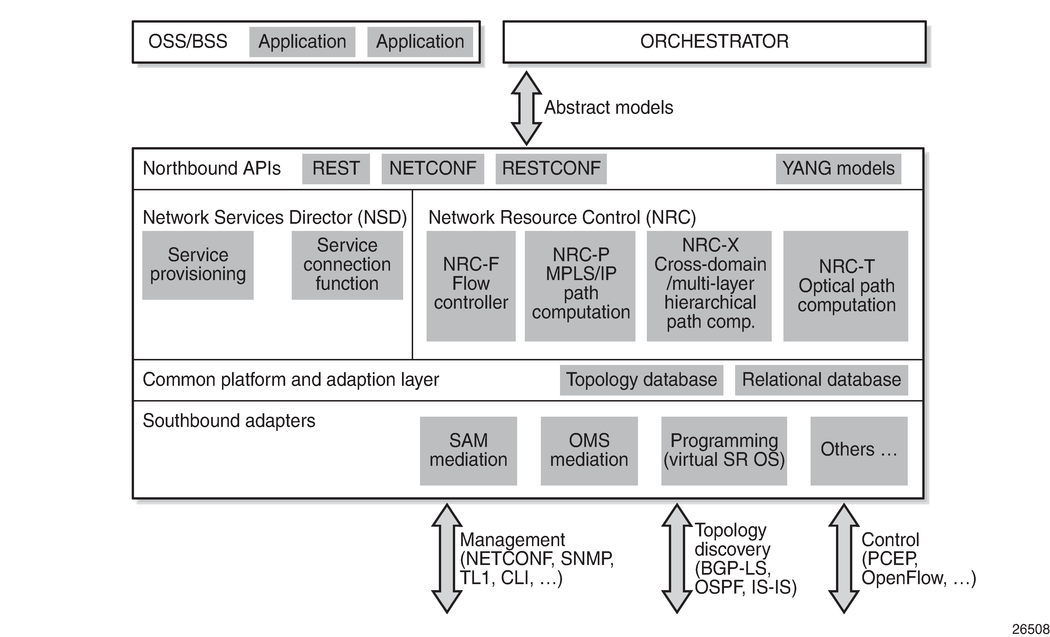
The creation of the vSR OS instance is outside the scope of this chapter. Also, there are several ways that the NRC-P can learn the network topology. For this chapter, it is just assumed that the NRC-P communication is configured, and that the complete topology database has been learned.
The following configuration describes how the NRC-P can compute an RSVP-TE LSP, for a:
path with no constraints (zero hop path)
path that is constrained using strict hops
primary and secondary standby path, constrained and diversely-routed using admin groups
Configuration
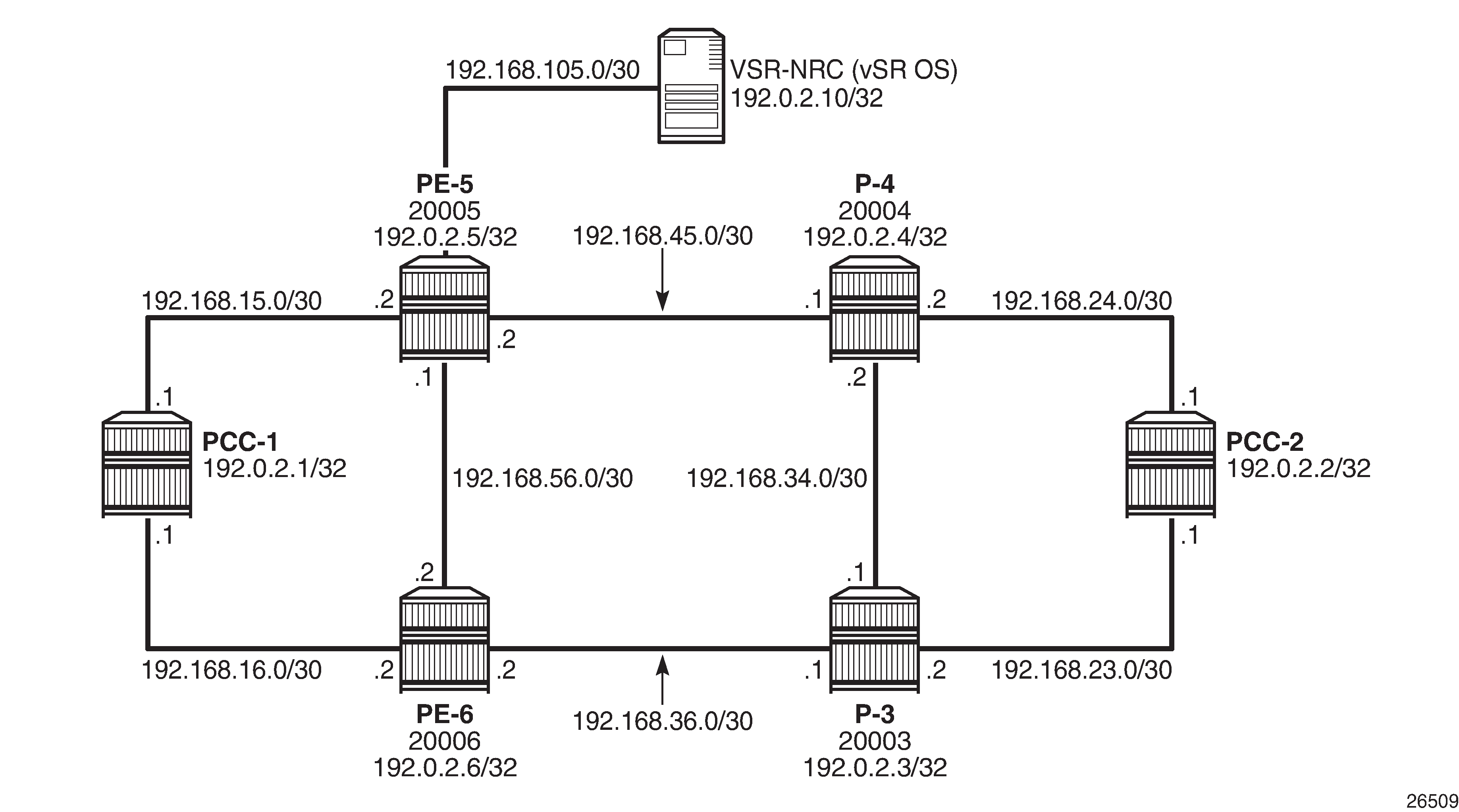
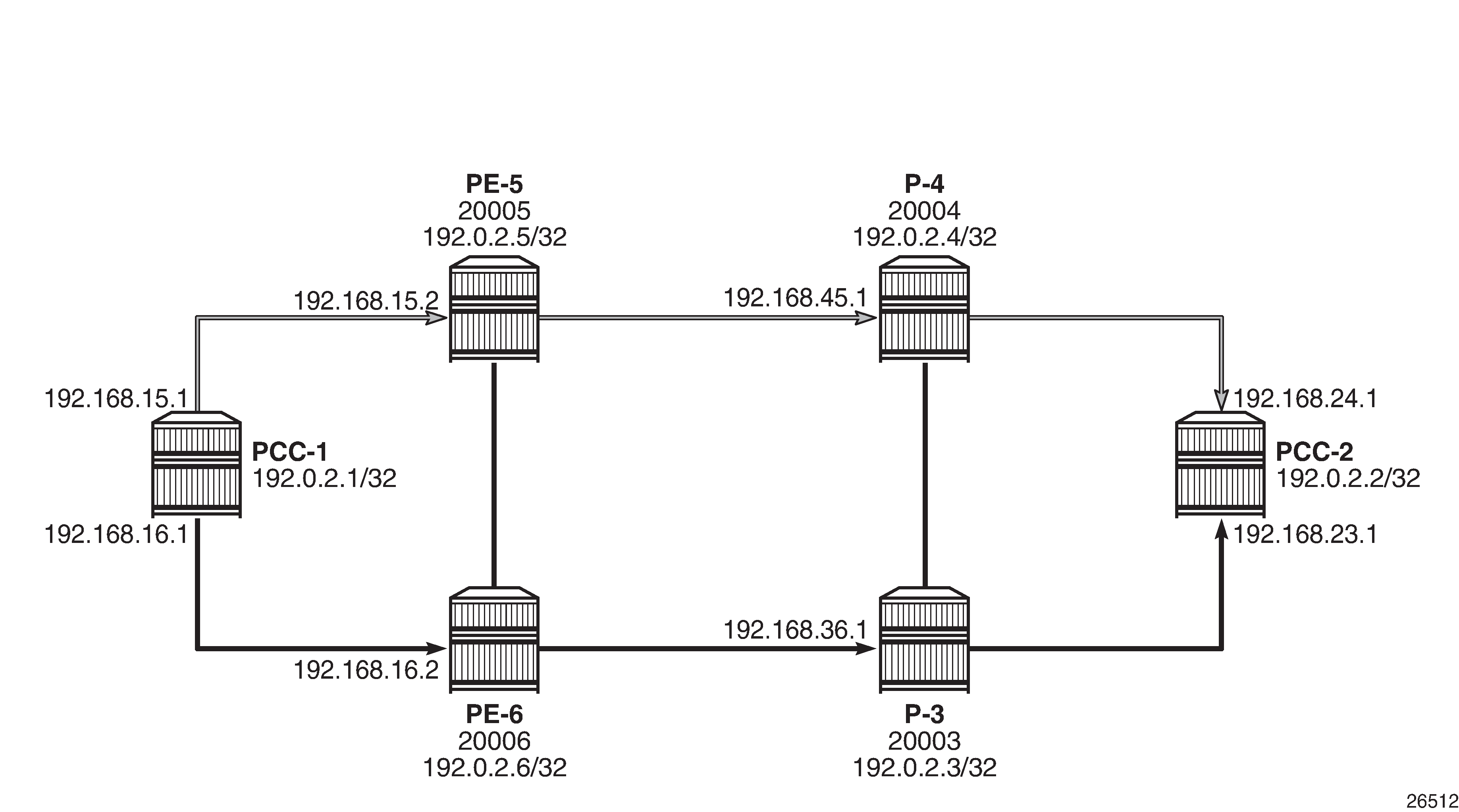
Example Topology shows the example topology. The VSR-NRC is connected to the network at PE-5. This vSR OS runs an IS-IS instance so that it is reachable by all routers in the network. For clarity, the NSP/NRC-P has been removed from the diagram. The NRC-P will be referred to as the Path Computation Element (PCE) throughout the remainder of the chapter.
Global IS-IS Configuration
The first step is to configure IS-IS on each router seen in Example Topology. All routers are members of a single level 2 area 49.0001.
The configuration for Path Computation Client PCC-1 to enable IS-IS is as follows:
A:PCC-1>config>router>isis# info
----------------------------------------------
            level-capability level-2
            area-id 49.0001
            level 2
                wide-metrics-only
            exit
            interface "system"
                level-capability level-2
                ipv4-node-sid index 420
                no shutdown
            exit
            interface "int-PCC-1-PE-5"
                level-capability level-2
                interface-type point-to-point
                level 2
                    metric 1000
                exit
                no shutdown
            exit
            interface "int-PCC-1-PE-6"
                level-capability level-2
                interface-type point-to-point
                level 2
                    metric 1000
                exit
                no shutdown
            exit
            no shutdown
The configuration for all other nodes is the same, apart from the IP addresses. The IP addresses can be derived from Example Topology.
Path Computation Element Protocol (PCEP)
The PCE is a vSR OS router instance serving as an interface between the physical network and the NRC-P. The instance has a direct physical connection to the network, and has a northbound interface toward the PCE within the NSP. The PCE communicates with its PCCs using the TCP-based protocol, PCEP. The TCP session is initiated by each client, but must be enabled on the PCE, as follows:
*A:PCE# configure router pcep
----------------------------------------------
            pce
                local-address 192.0.2.10
                no shutdown
            exit
----------------------------------------------
The local address is the system address, and is used as the source address for PCEP messaging between itself and the PCCs, when in-band communication is used. The management routing instance could also be used for out-of-band PCEP communication.
On each PCC, the PCE configuration specifies the VSR-NRC as the peer, using the local address of the PCE as the peer address, as follows:
A:PCC-1# configure router pcep
----------------------------------------------
            pcc
                local-address 192.0.2.1
                peer 192.0.2.10
                    no shutdown
                exit
                no shutdown
            exit
----------------------------------------------
Again, the local address is configured and is used as the source address for PCEP messages by the PCC. For in-band communication, the system address is used.
The following output shows the state of the PCEP sessions on the PCE. There are two sessions: one to each of PCC-1 and PCC-2.
*A:PCE# show router pcep pce peer

===============================================================================
PCEP Path Computation Element (PCE) Peer Info
===============================================================================
Peer                       Sync State             Oper Keepalive/Oper DeadTimer
-------------------------------------------------------------------------------
192.0.2.1:4189           done                   30/120
192.0.2.2:4189           done                   30/120
-------------------------------------------------------------------------------
No. of Peers: 2
===============================================================================
The PCEP session to PCC-1 is shown in more detail in the following output. The peer capabilities show that the computation of RSVP paths is supported. Stateful delegation capability is negotiated between the PCE and PCC. The PCC can delegate control of an LSP to the PCE so that if there is a requirement to modify the existing path of the LSP, the PCE will resignal a new path using a PCEP update message.
This PCEP session requires stateful PCE, so that the state of the LSP (both RSVP and Segment Routing TE (SR-TE) is reported to the PCE by the PCC. This state change could be a change in configuration, or any change due to a received PCE update.
*A:PCE# show router pcep pce peer 192.0.2.1

===============================================================================
PCEP Path Computation Element (PCE) Peer Info
===============================================================================
IP Address             : 192.0.2.1    Port                    : 4189
Sync State             : done
Peer Capabilities      : stateful-delegate stateful-pce segment-rt-path rsvp-
                         path
Speaker ID             : 2a:e1:ff:00:00:00
Session Establish Time : 8d 00:00:21
Oper Keepalive         : 30 seconds     Oper DeadTimer          : 120 seconds
===============================================================================
PCE Computed RSVP-TE LSP with Zero-hop Path
The following output shows an RSVP-TE LSP configured on PCC-1 with the tail end on PCC-2.
*A:PCC-1# configure router mpls
----------------------------------------------
    path "pce-controlled"
         no shutdown
    exit
    lsp "LSP-PCC-1-PCC-2"
                to 192.0.2.2
                cspf
                pce-computation
                pce-report enable
                pce-control
                primary "pce-controlled"
                exit
                no shutdown
            exit
The MPLS path is a loose path containing no hops and is applied as a primary path within the LSP construct.
The pce-computation command forces a PCEP Request by the router to the PCE for a valid path between PCC-1 and PCC-2, computed by the NRC-P. The PCE replies using a PCEP Reply with a valid path, or a no-path message if no valid path exists.
The PCC reports the state of the LSP to the PCE if the pce-report enable command is configured.
The pce-control command allows the router to delegate control of the LSP to the PCE. Because the PCE is aware of the full topology, if an event occurs that affects the state of the LSP, for example, a link or node failure, then the PCE will send a PCEP Update with a list of hops representing a new path (if a new path is available).
Debug: PCEP Messaging when LSP is Enabled
The following output shows the PCEP messaging in the form of debug, when the LSP is placed in a "no shutdown" state.
The PCC sends a PCReq message to the PCE, requesting the computation of an RSVP-TE Path. Because the PST(SegRt) field is set to zero, the path request is not a segment routing path request, so must be an RSVP-TE request. The PCEP LSP-ID (PLSP-ID) is set by the PCC. This value is used in all PCEP messages between PCE and PCC for the lifetime of the LSP. In this case, the value is set to 38. When the PCC or PCE sends a PCEP message with this value set, it refers to this specific LSP.
The source and destination addresses are 192.0.2.1 and 192.0.2.2, respectively. The LSP name and path name are shown in text form: LSP-PCC-1-PCC-2::pce-controlled.
10 2017/02/16 15:13:23.18 UTC MINOR: DEBUG #2001 Base PCC
"PCC: [TX-Msg: REQUEST ][001 23:53:12.130]
  Svec :{numOfReq 1}{nodeDiverse F linkDiverse F srlgDiverse F}
    Request: {id 29 PST(SegRt) 0 srcAddr 192.0.2.1 destAddr 192.0.2.2}
             {PLspId 38 tunnelId:3 lspId: 9736 lspName LSP-PCC-1-PCC-2::pce-controlled}
             {{bw 0 (0) isOpt: F}}
             {{setup 7 hold 0 exclAny 0 inclAny 0 inclAll 0 isOpt: F}}
             {{igp-met 16777215 B:F BVal:0 C:T isOpt: F}}
             {{hop-cnt 0 B:T BVal:255 C:T isOpt: F}}
The following shows the PCReply received by the PCC from the PCE, showing that a valid path has been computed within the constraints of the path request, and contains a list of strict IPv4 hops (isLoose flag is set to F (false), for each hop).
12 2017/02/16 15:13:23.26 UTC MINOR: DEBUG #2001 Base PCC
"PCC: [RX-Msg: REPLY ][001 23:53:12.210]
[Peer 192.0.2.10]
  Request: {id 29} {} Response has calculated path
        {{Total Paths: 1}}
          Path: {PST(SegRt) 0}
            {{ctype IPv4 addr 192.168.15.2/32 isLoose F}}
            {{ctype IPv4 addr 192.168.45.1/32 isLoose F}}
            {{ctype IPv4 addr 192.168.24.1/32 isLoose F}}
            {{Attr: {bw 0 te-metric 0 igp 1110 hop 3}}}
            {{      {setup 7 hold 0 exclAny 0 inclAny 0 inclAll 0}}}
Upon receipt of the PCReply, PCC-1 will signal the LSP with an RSVP Path message, as shown in the following output. The Path message contains an ERO comprising the same hops as those received in the PCReply.
29 2017/02/16 15:26:16.87 UTC MINOR: DEBUG #2001 Base RSVP
"RSVP: PATH Msg
Send PATH From:192.0.2.1, To:192.0.2.2
          TTL:255, Checksum:0xc440, Flags:0x1
MSG ID     - Flags:0x1, Epoch:10790745, MsgId:128
Session    - EndPt:192.0.2.2, TunnId:3, ExtTunnId:192.0.2.1
SessAttr   - Name:LSP-PCC-1-PCC-2::pce-controlled
             SetupPri:7, HoldPri:0, Flags:0x6
RSVPHop    - Ctype:1, Addr:192.168.15.1, LIH:2
TimeValue  - RefreshPeriod:180
SendTempl  - Sender:192.0.2.1, LspId:9740
SendTSpec  - Ctype:QOS, CDR:0.000 bps, PBS:0.000 bps, PDR:infinity
             MPU:20, MTU:8686
LabelReq   - IfType:General, L3ProtID:2048
RRO        - IpAddr:192.168.15.1, Flags:0x0
ERO        - IPv4Prefix 192.168.15.2/32, Strict
             IPv4Prefix 192.168.45.1/32, Strict
             IPv4Prefix 192.168.24.1/32, Strict
"
PCC-1 receives an RSVP Resv message with the RRO containing a list of hops, with a label mapping per hop.
30 2017/02/16 15:26:16.88 UTC MINOR: DEBUG #2001 Base RSVP
"RSVP: RESV Msg
Recv RESV From:192.168.15.2, To:192.168.15.1
          TTL:255, Checksum:0xfa6a, Flags:0x1
MSG ID     - Flags:0x1, Epoch:14080719, MsgId:35
Session    - EndPt:192.0.2.2, TunnId:3, ExtTunnId:192.0.2.1
RSVPHop    - Ctype:1, Addr:192.168.15.2, LIH:2
TimeValue  - RefreshPeriod:180
Style      - SE
FlowSpec   - Ctype:QOS, CDR:0.000 bps, PBS:0.000 bps, PDR:infinity
             MPU:20, MTU:8686, RSpecRate:0, RSpecSlack:0
FilterSpec - Sender:192.0.2.1, LspId:9740, Label:262120
LspAttr    - Attribute Flags TLV  0x400000
RRO        - InterfaceIp:192.168.15.2, Flags:0x0
             Label:262120, Flags:0x1
             InterfaceIp:192.168.45.1, Flags:0x0
             Label:262105, Flags:0x1
             InterfaceIp:192.168.24.1, Flags:0x0
             Label:262134, Flags:0x1
The PCC then sends a PC LSP State Report message to the PCE with the state of the LSP set to Admin=1 (up), and OperState = 2 (up and carrying traffic).
The ERO is a copy of the ERO contained in the PCReply, and the RRO is a copy of the RRO contained in the RSVP Resv message.
"PCC: [TX-Msg: REPORT ][002 00:06:05.830]
[Peer 192.0.2.10]
  Report : {srpId:0 PST(SegRt):0 PLspId:40 lspId: 9740 tunnelId:3}
    {Sync 0 Rem 0 AdminState 1 OperState 2 Delegate 1 Create 0}
    {srcAddr 192.0.2.1 destAddr 192.0.2.2 extTunnelId :: pathName LSP-PCC-1-PCC-2::
                                                         pce-controlled}
    {Binding Type: 0 Binding Val : 0}
    Lsp Constraints:
             {{bw 0 isOpt: F}}
             {{setup 7 hold 0 exclAny 0 inclAny 0 inclAll 0 isOpt: F}}
             {{igp-met 16777215 B:F BVal:0 C:T isOpt: F}}
             {{hop-cnt 0 B:T BVal:255 C:T isOpt: F}}
      Ero Path:
            {{ctype IPv4 addr 192.168.15.2/32 isLoose F}}
            {{ctype IPv4 addr 192.168.45.1/32 isLoose F}}
            {{ctype IPv4 addr 192.168.24.1/32 isLoose F}}
            {{Attr: {bw 0 te-metric 0 igp 1110 hop 4}}}
            {{      {setup 7 hold 0 exclAny 0 inclAny 0 inclAll 0}}}
      RRO:
            {{type IPv4 addr 192.168.15.1/32 Flag 0}}
            {{type IPv4 addr 192.168.15.2/32 Flag 0}}
            {{type Label label c-type 1 label 262120}}
            {{type IPv4 addr 192.168.45.1/32 Flag 0}}
            {{type Label label c-type 1 label 262105}}
            {{type IPv4 addr 192.168.24.1/32 Flag 0}}
            {{type Label label c-type 1 label 262134}}
      {Lsp Err NA RsvpErr 0 LspDbVersion 0}
When the LSP has connected, the following show command output shows the state of the LSP Path.
*A:PCC-1# show router mpls lsp "LSP-PCC-1-PCC-2" path detail

===============================================================================
MPLS LSP LSP-PCC-1-PCC-2 Path  (Detail)
===============================================================================
Legend :
    @ - Detour Available              # - Detour In Use
    b - Bandwidth Protected           n - Node Protected
    s - Soft Preemption
    S - Strict                        L - Loose
    A - ABR                           + - Inherited
===============================================================================
-------------------------------------------------------------------------------
LSP LSP-PCC-1-PCC-2 Path pce-controlled
-------------------------------------------------------------------------------
LSP Name         : LSP-PCC-1-PCC-2
Path LSP ID      : 9740
From             : 192.0.2.1          To                   : 192.0.2.2
Admin State      : Up                   Oper State           : Up
Path Name        : pce-controlled       Path Type            : Primary
Path Admin       : Up                   Path Oper            : Up
Out Interface    : 1/1/1:220            Out Label            : 262114
Path Up Time     : 0d 00:09:06          Path Down Time       : 0d 00:00:00
Retry Limit      : 0                    Retry Timer          : 30 sec
Retry Attempt    : 0                    Next Retry In        : 0 sec
BFD Template     : None                 BFD Ping Interval    : 60
BFD Enable       : False

Adspec           : Disabled             Oper Adspec          : Disabled
CSPF             : Enabled              Oper CSPF            : Enabled
Least Fill       : Disabled             Oper LeastFill       : Disabled
FRR              : Disabled             Oper FRR             : Disabled
Propogate Adm Grp: Disabled             Oper Prop Adm Grp    : Disabled
Inter-area       : False

PCE Updt ID      : 0

PCE Report       : Enabled              Oper PCE Report      : Enabled
PCE Control      : Enabled              Oper PCE Control     : Disabled
PCE Compute      : Enabled              Oper PCE Compute     : Disabled

Neg MTU          : 8686                 Oper MTU             : 8686
Bandwidth        : No Reservation       Oper Bandwidth       : 0 Mbps
Hop Limit        : 255                  Oper HopLimit        : 255
Record Route     : Record               Oper Record Route    : Record
Record Label     : Record               Oper Record Label    : Record
Setup Priority   : 7                    Oper Setup Priority  : 7
Hold Priority    : 0                    Oper Hold Priority   : 0
Class Type       : 0                    Oper CT              : 0
Backup CT        : None
MainCT Retry     : n/a
    Rem          :
MainCT Retry     : 0
    Limit        :
Include Groups   :                      Oper Include Groups  :
None                                           None
Exclude Groups   :                      Oper Exclude Groups  :
None                                           None

Adaptive         : Enabled              Oper Metric          : 1110
Preference       : n/a
Path Trans       : 3                    CSPF Queries         : 2
Failure Code     : noError
Failure Node     : n/a
Explicit Hops    :
    No Hops Specified
Actual Hops      :
    192.168.15.1 (192.0.2.1)                    Record Label        : N/A
 -> 192.168.15.2 (192.0.2.5)                    Record Label        : 262120
 -> 192.168.45.1 (192.0.2.4)                    Record Label        : 262105
 -> 192.168.24.1 (192.0.2.2)                    Record Label        : 262134
Computed Hops    :
    192.168.15.1(S)
 -> 192.168.15.2(S)
 -> 192.168.45.1(S)
 -> 192.168.24.1(S)
Resignal Eligible: False
Last Resignal    : n/a                  CSPF Metric          : 1110
===============================================================================
PCE-Computed RSVP-TE LSP with Strict Hop Path
It is possible for the PCC to influence the path computed by the PCE by including a primary path with one or more explicit hops. This path is translated into a list of hops in the Include Route Object (IRO) in the PCEP PC Request, which is sent from the PCC to the PCE at the time of the path request.
The PCE will take the hops listed in the IRO into account when computing an end-to-end path, as the following example shows.
RSVP-TE LSP with Strict Hops shows an RSVP-TE LSP with source PCC-1 and destination PCC-2, which has a requirement to follow a path via PE-5, PE-6, and P-3.
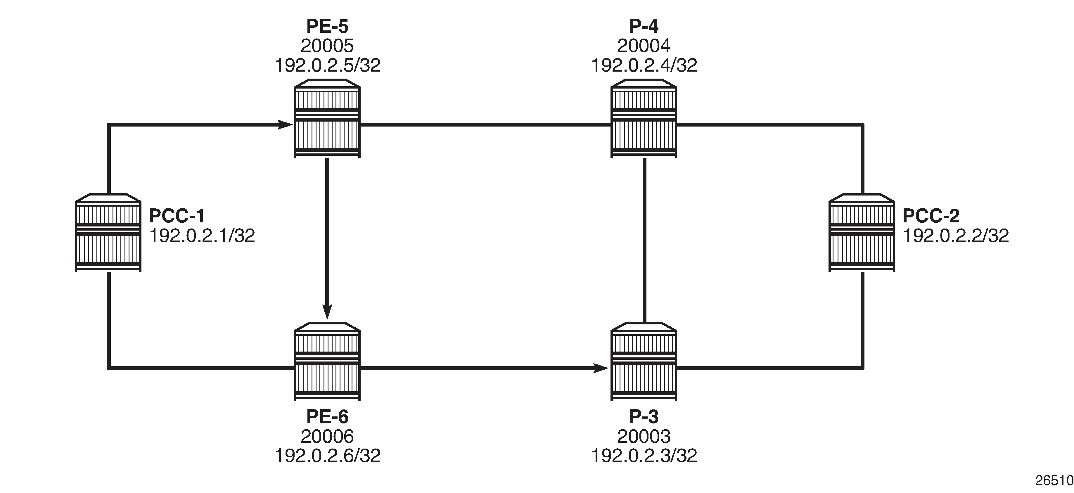
The following output shows the path converted to a list of strict hops.
*A:PCC-1>config>router>mpls# path pce-controlled-strict
----------------------------------------------
                hop 1 192.0.2.5 strict
                hop 2 192.0.2.6 strict
                hop 3 192.0.2.3 strict
                no shutdown
The use of strict hops requires that each consecutive hop must be contiguous from the previous hop. Applying this path to an RSVP-TE LSP with PCEP commands included is as follows:
*A:PCC-1>config>router>mpls# lsp "PCC-1-PCC-2-RSVP-PCE-strict-001"
----------------------------------------------
                to 192.0.2.2
                cspf
                pce-computation
                pce-report enable
                pce-control
                primary "pce-controlled-strict"
                exit
                no shutdown
The following show command output shows that the LSP path is connected.
*A:PCC-1# show router mpls lsp "PCC-1-PCC-2-RSVP-PCE-strict-001" path detail

===============================================================================
MPLS LSP PCC-1-PCC-2-RSVP-PCE-strict-001 Path  (Detail)
===============================================================================
Legend :
    @ - Detour Available              # - Detour In Use
    b - Bandwidth Protected           n - Node Protected
    s - Soft Preemption
    S - Strict                        L - Loose
    A - ABR                           + - Inherited
===============================================================================
-------------------------------------------------------------------------------
LSP PCC-1-PCC-2-RSVP-PCE-strict-001 Path pce-controlled-strict
-------------------------------------------------------------------------------
LSP Name         : PCC-1-PCC-2-RSVP-PCE-strict-001
Path LSP ID      : 31746
From             : 192.0.2.1          To                   : 192.0.2.2
Admin State      : Up                   Oper State           : Up
Path Name        : pce-controlled-      Path Type            : Primary
                   strict
Path Admin       : Up                   Path Oper            : Up
Out Interface    : 1/1/1:220            Out Label            : 262088
Path Up Time     : 0d 00:00:53          Path Down Time       : 0d 00:00:00
Retry Limit      : 0                    Retry Timer          : 30 sec
Retry Attempt    : 0                    Next Retry In        : 0 sec
BFD Template     : None                 BFD Ping Interval    : 60
BFD Enable       : False

Adspec           : Disabled             Oper Adspec          : Disabled
CSPF             : Enabled              Oper CSPF            : Enabled
Least Fill       : Disabled             Oper LeastFill       : Disabled
FRR              : Disabled             Oper FRR             : Disabled
Propogate Adm Grp: Disabled             Oper Prop Adm Grp    : Disabled
Inter-area       : False

PCE Updt ID      : 0

PCE Report       : Enabled              Oper PCE Report      : Enabled
PCE Control      : Enabled              Oper PCE Control     : Enabled
PCE Compute      : Enabled              Oper PCE Compute     : Enabled

Neg MTU          : 8686                 Oper MTU             : 8686
Bandwidth        : No Reservation       Oper Bandwidth       : 0 Mbps
Hop Limit        : 255                  Oper HopLimit        : 255
Record Route     : Record               Oper Record Route    : Record
Record Label     : Record               Oper Record Label    : Record
Setup Priority   : 7                    Oper Setup Priority  : 7
Hold Priority    : 0                    Oper Hold Priority   : 0
Class Type       : 0                    Oper CT              : 0
Backup CT        : None
MainCT Retry     : n/a
    Rem          :
MainCT Retry     : 0
    Limit        :
Include Groups   :                      Oper Include Groups  :
None                                           None
Exclude Groups   :                      Oper Exclude Groups  :
None                                           None

Adaptive         : Enabled              Oper Metric          : 2200
Preference       : n/a
Path Trans       : 3                    CSPF Queries         : 0
Failure Code     : noError
Failure Node     : n/a
Explicit Hops    :
    192.0.2.5(S)      -> 192.0.2.6(S)      -> 192.0.2.3(S)
Actual Hops      :
    192.168.15.1 (192.0.2.1)                    Record Label        : N/A
 -> 192.168.15.2 (192.0.2.5)                    Record Label        : 262088
 -> 192.168.56.2 (192.0.2.6)                    Record Label        : 262088
 -> 192.168.36.1 (192.0.2.3)                    Record Label        : 262070
 -> 192.168.23.1 (192.0.2.2)                    Record Label        : 262112
Computed Hops    :
    192.168.15.2(S)
 -> 192.168.56.2(S)
 -> 192.168.36.1(S)
 -> 192.168.23.1(S)
Resignal Eligible: False
Last Resignal    : n/a                  CSPF Metric          : 2200
The explicit hops of the path configuration are shown, with the "(S)" signifying that the hops are configured as strict hops. The "Actual Hops" show that the strict hops are enforced as per the RSVP-TE LSP configuration. The "Computed Hops" are taken from the Path object in PCEP Reply, as shown in the following debug output.
Debug: PCEP Messaging for Path Computation
The PCC sends a PCReq message to the PCE requesting the computation of an RSVP-TE Path. The source and destination addresses are 192.0.2.1 and 192.0.2.2, respectively. The LSP name and path name are shown in text form: PCC-1-PCC-2-RSVP-PCE-strict-001::pce-controlled-strict. The request contains an IRO, containing the configured hops from the MPLS path configuration. Each hop contains an isLoose flag set to F (false), which implies that the hop is strict (that is, not loose). The following debug output shows the PCEP messaging.
UTC MINOR: DEBUG #2001 Base PCC
"PCC: [TX-Msg: REQUEST ]
  Svec :{numOfReq 1}{nodeDiverse F linkDiverse F srlgDiverse F}
    Request: {id 13281 PST(SegRt) 0 srcAddr 192.0.2.1 destAddr 192.0.2.2}
             {PLspId 13314 tunnelId:2 lspId: 31746 lspName PCC-1-PCC-2-RSVP-PCE-strict-001::pce-controlled-strict}
             {{bw 0 (0) isOpt: F}}
             {{setup 7 hold 0 exclAny 0 inclAny 0 inclAll 0 isOpt: F}}
             {{igp-met 16777215 B:F BVal:0 C:T isOpt: F}}
             {{hop-cnt 0 B:T BVal:255 C:T isOpt: F}}
             {{iro isOpt: F}}
                 {{ctype IPv4 addr 192.0.2.5/0 isLoose F}}
                 {{ctype IPv4 addr 192.0.2.6/0 isLoose F}}
                 {{ctype IPv4 addr 192.0.2.3/0 isLoose F}}
"
The PCReply received by PCC-1 from the PCE has computed a valid path. This is shown in the following output.
6 2017/03/15 15:36:05.55 UTC MINOR: DEBUG #2001 Base PCC
"PCC: [RX-Msg: REPLY ][022 01:06:53.520]
[Peer 192.0.2.10]
  Request: {id 13281} {} Response has calculated path
        {{Total Paths: 1}}
          Path: {PST(SegRt) 0}
            {{ctype IPv4 addr 192.168.15.2/32 isLoose F}}
            {{ctype IPv4 addr 192.168.56.2/32 isLoose F}}
            {{ctype IPv4 addr 192.168.36.1/32 isLoose F}}
            {{ctype IPv4 addr 192.168.23.1/32 isLoose F}}
            {{Attr: {bw 0 te-metric 0 igp 2200 hop 4}}}
            {{      {setup 7 hold 0 exclAny 0 inclAny 0 inclAll 0}}}
"
The path in the PCReply is the path replicated in the "Computed Hops" of the preceding show router mpls lsp path detail command output.
Upon receipt of the PCReply from the PCE, the PCC uses the computed hops from the PCReply in the ERO of the RSVP Path message.
7 2017/03/15 15:36:05.54 UTC MINOR: DEBUG #2001 Base RSVP
"RSVP: PATH Msg
Send PATH From:192.0.2.1, To:192.0.2.2
          TTL:255, Checksum:0x5311, Flags:0x1
MSG ID     - Flags:0x1, Epoch:2387139, MsgId:8165
Session    - EndPt:192.0.2.2, TunnId:2, ExtTunnId:192.0.2.1
SessAttr   - Name:PCC-1-PCC-2-RSVP-PCE-strict-001::pce-controlled-strict
             SetupPri:7, HoldPri:0, Flags:0x6
RSVPHop    - Ctype:1, Addr:192.168.15.1, LIH:2
TimeValue  - RefreshPeriod:180
SendTempl  - Sender:192.0.2.1, LspId:31746
SendTSpec  - Ctype:QOS, CDR:0.000 bps, PBS:0.000 bps, PDR:infinity
             MPU:20, MTU:8686
LabelReq   - IfType:General, L3ProtID:2048
RRO        - IpAddr:192.168.15.1, Flags:0x0
ERO        - IPv4Prefix 192.168.15.2/32, Strict
             IPv4Prefix 192.168.56.2/32, Strict
             IPv4Prefix 192.168.36.1/32, Strict
             IPv4Prefix 192.168.23.1/32, Strict
"
A PCEP Report is then sent to the PCE when the path is connected.
8 2017/03/15 15:36:05.56 UTC MINOR: DEBUG #2001 Base PCC
"PCC: [TX-Msg: REPORT ][022 01:06:53.540]
[Peer 192.0.2.10]
  Report : {srpId:0 PST(SegRt):0 PLspId:13314 lspId: 31746 tunnelId:2}
    {Sync 0 Rem 0 AdminState 1 OperState 2 Delegate 1 Create 0}
    {srcAddr 192.0.2.1 destAddr 192.0.2.2 extTunnelId ::
                   pathName PCC-1-PCC-2-rsvp-pce-strict-001::pce-controlled-strict}
    {Binding Type: 0 Binding Val : 0}
    Lsp Constraints:
             {{bw 0 isOpt: F}}
             {{setup 7 hold 0 exclAny 0 inclAny 0 inclAll 0 isOpt: F}}
             {{igp-met 16777215 B:F BVal:0 C:T isOpt: F}}
             {{hop-cnt 0 B:T BVal:255 C:T isOpt: F}}
             {{iro isOpt: F}}
                 {{ctype IPv4 addr 192.0.2.5/0 isLoose F}}
                 {{ctype IPv4 addr 192.0.2.6/0 isLoose F}}
                 {{ctype IPv4 addr 192.0.2.3/0 isLoose F}}
      Ero Path:
            {{ctype IPv4 addr 192.168.15.2/32 isLoose F}}
            {{ctype IPv4 addr 192.168.56.2/32 isLoose F}}
            {{ctype IPv4 addr 192.168.36.1/32 isLoose F}}
            {{ctype IPv4 addr 192.168.23.1/32 isLoose F}}
            {{Attr: {bw 0 te-metric 0 igp 2200 hop 5}}}
            {{      {setup 7 hold 0 exclAny 0 inclAny 0 inclAll 0}}}
      RRO:
            {{type IPv4 addr 192.168.15.1/32 Flag 0}}
            {{type IPv4 addr 192.168.15.2/32 Flag 0}}
            {{type Label label c-type 1 label 262088}}
            {{type IPv4 addr 192.168.56.2/32 Flag 0}}
            {{type Label label c-type 1 label 262088}}
            {{type IPv4 addr 192.168.36.1/32 Flag 0}}
            {{type Label label c-type 1 label 262070}}
            {{type IPv4 addr 192.168.23.1/32 Flag 0}}
            {{type Label label c-type 1 label 262112}}
      {Lsp Err NA RsvpErr 0 LspDbVersion 0}
"
PCE-Computed RSVP-TE LSP with Primary and Secondary Paths using Admin Groups for Diversity
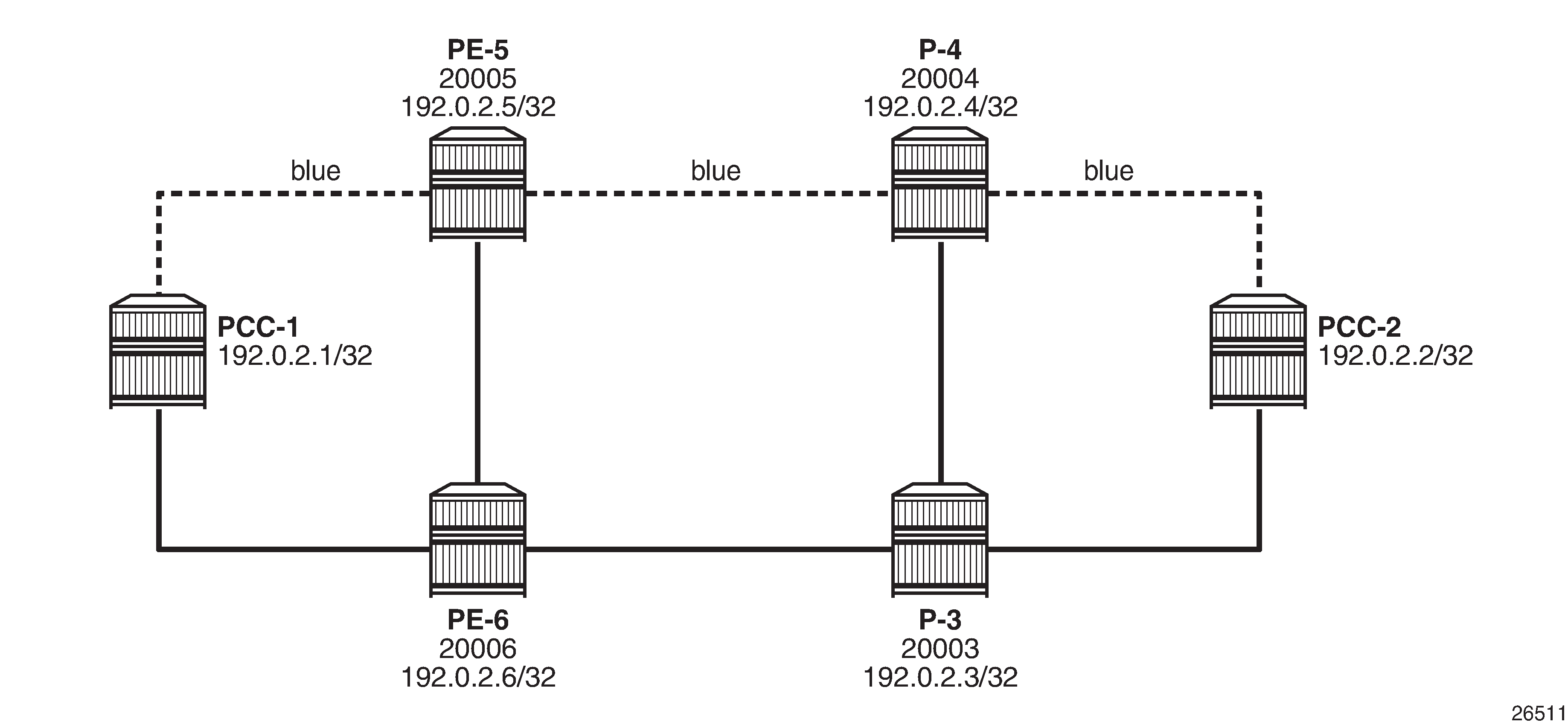
The PCE can compute primary and secondary paths on behalf of the PCC. Admin groups can be used to ensure that the zero-hop paths are diverse.
Admin Groups shows that there are two diverse paths between PCC-1 and PCC-2. The upper path via PE-5 and P-4 will have interfaces configured with an admin group called "blue".
Admin groups are configured under the configure router context, and are applied to the router interface under the configure router mpls context. The following output is an example of an admin group created and applied on router PCC-1.
A:PCC-1>config>router# info
--------------------------------------------------
        if-attribute
            admin-group "blue" value 10
        exit
        mpls
            interface "int-PCC-1-PE-5"
                admin-group "blue"
                no shutdown
            exit
        exit
Similarly, for PE-5, the admin group configuration is as follows:
A:PE-5>config>router# info
--------------------------------------------------
        if-attribute
            admin-group "blue" value 10
        exit
        mpls
             interface "int-PE-5-PCC-1"
                admin-group "blue"
                no shutdown
            exit
            interface "int-PE-5-P-4"
                admin-group "blue"
                no shutdown
            exit
       exit
The admin group is also configured on P-4 and on PCC-2, so that there is a continuous path between PCC-1 and PCC-2 comprising interfaces that are included in the admin group. The value argument within the admin group configuration must be configured with the same value on each router; in this case, 10.
The presence of the admin group on each interface is advertised by IS-IS, so that each router is aware of all interfaces in the admin group. The PCE is also aware of the admin groups via its topology database.
In this example, a primary and secondary path will be used, so it is necessary to configure two separate MPLS path statements, as in the following output (primary and secondary paths of the same LSP cannot use the same MPLS path).
*A:PCC-1>config>router>mpls# info
----------------------------------------------
            path "pce-secondary"
                no shutdown
            exit
            path "pce-controlled"
                no shutdown
            exit
These path statements are applied within the configuration of the LSP and the admin group constraints are applied to each path, as in the following output.
            lsp "PCC-1-PCC-2-RSVP-PCE-ag-001"
                to 192.0.2.2
                cspf
                pce-computation
                pce-report enable
                pce-control
                primary "pce-controlled"
                    include "blue"
                exit
                secondary "pce-secondary"
                    standby
                    exclude "blue"
                exit
                no shutdown
The primary path must follow the path where the interfaces are included in the admin group "blue", whereas the secondary must not use any interface in the admin group; therefore, the exclude "blue" command within the secondary context. The secondary is configured as standby, so will be connected.
Debug: PCEP Requests for Primary and Secondary Paths
When the LSP is placed into a "no shutdown" state, the router initiates a separate PCEP Request for each of the primary and secondary paths, as shown in the following debug output.
#Primary Path Request
UTC MINOR: DEBUG #2001 Base PCC
"PCC: [TX-Msg: REQUEST ][023 00:15:04.160]
  Svec :{numOfReq 1}{nodeDiverse F linkDiverse F srlgDiverse F}
    Request: {id 13284 PST(SegRt) 0 srcAddr 192.0.2.1 destAddr 192.0.2.2}
             {PLspId 13317 tunnelId:4 lspId: 49158
                     lspName PCC-1-PCC-2-rsvp-pce-ag-001::pce-controlled}
             {{bw 0 (0) isOpt: F}}
             {{setup 7 hold 0 exclAny 0 inclAny 1024 inclAll 0 isOpt: F}}
             {{igp-met 16777215 B:F BVal:0 C:T isOpt: F}}
             {{hop-cnt 0 B:T BVal:255 C:T isOpt: F}}
"

#Secondary Path Request
UTC MINOR: DEBUG #2001 Base PCC
"PCC: [TX-Msg: REQUEST ][023 00:15:04.160]
  Svec :{numOfReq 1}{nodeDiverse F linkDiverse F srlgDiverse F}
    Request: {id 13285 PST(SegRt) 0 srcAddr 192.0.2.1 destAddr 192.0.2.2}
             {PLspId 13318 tunnelId:4 lspId: 49154
                     lspName PCC-1-PCC-2-rsvp-pce-ag-001::pce-secondary}
             {{bw 0 (0) isOpt: F}}
             {{setup 7 hold 0 exclAny 1024 inclAny 0 inclAll 0 isOpt: F}}
             {{igp-met 16777215 B:F BVal:0 C:T isOpt: F}}
             {{hop-cnt 0 B:T BVal:255 C:T isOpt: F}}
"
The PCEP message exchange can be identified by the request ID, and the textual LSP Name and path name are visible. The request message also shows that the admin group is signaled via the "inclAny 1024" and "exclAny 1024". The argument of 1024 corresponds to the original value of 10, where the admin group argument signaled = 2value = (210) = 1024, as configured within the configure router if-attribute context.
The following debug output corresponds to the PCReply to the PCReq for the primary path - they have the same request ID of 13284. A valid path has been computed and a list of strict hops (isLoose = F) is returned.
22 2017/03/16 14:44:16.29 UTC MINOR: DEBUG #2001 Base PCC
"PCC: [RX-Msg: REPLY ][023 00:15:04.260]
[Peer 192.0.2.10]
  Request: {id 13284} {} Response has calculated path
        {{Total Paths: 1}}
          Path: {PST(SegRt) 0}
            {{ctype IPv4 addr 192.168.15.2/32 isLoose F}}
            {{ctype IPv4 addr 192.168.45.1/32 isLoose F}}
            {{ctype IPv4 addr 192.168.24.1/32 isLoose F}}
            {{Attr: {bw 0 te-metric 0 igp 2100 hop 3}}}
            {{      {setup 7 hold 0 exclAny 0 inclAny 1024 inclAll 0}}}
"
When the PCEP Reply is received with a valid path, PCC-1 originates an RSVP Path message, as in the following debug output.
23 2017/03/16 14:44:16.29 UTC MINOR: DEBUG #2001 Base RSVP
"RSVP: PATH Msg
Send PATH From:192.0.2.1, To:192.0.2.2
          TTL:255, Checksum:0x6575, Flags:0x1
MSG ID     - Flags:0x1, Epoch:2387139, MsgId:8389
Session    - EndPt:192.0.2.2, TunnId:4, ExtTunnId:192.0.2.1
SessAttr   - Name:PCC-1-PCC-2-RSVP-PCE-ag-001::pce-controlled
             SetupPri:7, HoldPri:0, Flags:0x6
RSVPHop    - Ctype:1, Addr:192.168.15.1, LIH:2
TimeValue  - RefreshPeriod:180
SendTempl  - Sender:192.0.2.1, LspId:49158
SendTSpec  - Ctype:QOS, CDR:0.000 bps, PBS:0.000 bps, PDR:infinity
             MPU:20, MTU:8686
LabelReq   - IfType:General, L3ProtID:2048
RRO        - IpAddr:192.168.15.1, Flags:0x0
ERO        - IPv4Prefix 192.168.15.2/32, Strict
             IPv4Prefix 192.168.45.1/32, Strict
             IPv4Prefix 192.168.24.1/32, Strict
"
An RSVP Resv message is received, as follows:
24 2017/03/16 14:44:16.30 UTC MINOR: DEBUG #2001 Base RSVP
"RSVP: RESV Msg
Recv RESV From:192.168.15.2, To:192.168.15.1
          TTL:255, Checksum:0xcda7, Flags:0x1
MSG ID     - Flags:0x1, Epoch:16280838, MsgId:185
Session    - EndPt:192.0.2.2, TunnId:4, ExtTunnId:192.0.2.1
FlowSpec   - Ctype:QOS, CDR:0.000 bps, PBS:0.000 bps, PDR:infinity
             MPU:20, MTU:8686, RSpecRate:0, RSpecSlack:0
FilterSpec - Sender:192.0.2.1, LspId:49158, Label:262107
LspAttr    - Attribute Flags TLV  0x400000
RRO        - InterfaceIp:192.168.15.2, Flags:0x0
             Label:262107, Flags:0x1
             InterfaceIp:192.168.45.1, Flags:0x0
             Label:262090, Flags:0x1
             InterfaceIp:192.168.24.1, Flags:0x0
             Label:262136, Flags:0x1
"
PCC-1 now originates a PCEP Report and forwards it to the PCE, reporting the state of the LSP.
UTC MINOR: DEBUG #2001 Base PCC
"PCC: [TX-Msg: REPORT ][023 00:15:04.270]
[Peer 192.0.2.10]
  Report : {srpId:0 PST(SegRt):0 PLspId:13317 lspId: 49158 tunnelId:4}
    {Sync 0 Rem 0 AdminState 1 OperState 2 Delegate 1 Create 0}
    {srcAddr 192.0.2.1 destAddr 192.0.2.2 extTunnelId :: pathName PCC-1-PCC-2-
rsvp-pce-ag-001::pce-controlled}
    {Binding Type: 0 Binding Val : 0}
    Lsp Constraints:
             {{bw 0 isOpt: F}}
             {{setup 7 hold 0 exclAny 0 inclAny 1024 inclAll 0 isOpt: F}}
             {{igp-met 16777215 B:F BVal:0 C:T isOpt: F}}
             {{hop-cnt 0 B:T BVal:255 C:T isOpt: F}}
      Ero Path:
            {{ctype IPv4 addr 192.168.15.2/32 isLoose F}}
            {{ctype IPv4 addr 192.168.45.1/32 isLoose F}}
            {{ctype IPv4 addr 192.168.24.1/32 isLoose F}}
            {{Attr: {bw 0 te-metric 0 igp 2100 hop 4}}}
            {{      {setup 7 hold 0 exclAny 0 inclAny 1024 inclAll 0}}}
      RRO:
            {{type IPv4 addr 192.168.15.1/32 Flag 0}}
            {{type IPv4 addr 192.168.15.2/32 Flag 0}}
            {{type Label label c-type 1 label 262107}}
            {{type IPv4 addr 192.168.45.1/32 Flag 0}}
            {{type Label label c-type 1 label 262090}}
            {{type IPv4 addr 192.168.24.1/32 Flag 0}}
            {{type Label label c-type 1 label 262136}}
      {Lsp Err NA RsvpErr 0 LspDbVersion 0}
"
A valid path for the secondary LSP path is shown in the second PCEP Reply with a request ID of 13285. The message also contains a non-zero value (set to 1024) for the exclAny parameter, so that the computation excludes the "blue" admin group.
The list of hops is shown in the following output.
UTC MINOR: DEBUG #2001 Base PCC
"PCC: [RX-Msg: REPLY ][023 00:15:04.290]
[Peer 192.0.2.10]
  Request: {id 13285} {} Response has calculated path
        {{Total Paths: 1}}
          Path: {PST(SegRt) 0}
            {{ctype IPv4 addr 192.168.16.2/32 isLoose F}}
            {{ctype IPv4 addr 192.168.36.1/32 isLoose F}}
            {{ctype IPv4 addr 192.168.23.1/32 isLoose F}}
            {{Attr: {bw 0 te-metric 0 igp 2100 hop 3}}}
            {{      {setup 7 hold 0 exclAny 1024 inclAny 0 inclAll 0}}}
"
When the PCEP Reply is received, the list of hops is used within the ERO of the RSVP Path message.
UTC MINOR: DEBUG #2001 Base RSVP
"RSVP: PATH Msg
Send PATH From:192.0.2.1, To:192.0.2.2
          TTL:255, Checksum:0xd66a, Flags:0x1
MSG ID     - Flags:0x1, Epoch:2387139, MsgId:8390
Session    - EndPt:192.0.2.2, TunnId:4, ExtTunnId:192.0.2.1
SessAttr   - Name:PCC-1-PCC-2-RSVP-PCE-ag-001::pce-secondary
             SetupPri:7, HoldPri:0, Flags:0x6
RSVPHop    - Ctype:1, Addr:192.168.16.1, LIH:3
TimeValue  - RefreshPeriod:180
SendTempl  - Sender:192.0.2.1, LspId:49154
SendTSpec  - Ctype:QOS, CDR:0.000 bps, PBS:0.000 bps, PDR:infinity
             MPU:20, MTU:8690
LabelReq   - IfType:General, L3ProtID:2048
RRO        - IpAddr:192.168.16.1, Flags:0x0
ERO        - IPv4Prefix 192.168.16.2/32, Strict
             IPv4Prefix 192.168.36.1/32, Strict
             IPv4Prefix 192.168.23.1/32, Strict
"
An RSVP Resv message is received containing the RRO with the label allocations for each hop.
29 2017/03/16 14:44:16.32 UTC MINOR: DEBUG #2001 Base RSVP
"RSVP: RESV Msg
Recv RESV From:192.168.16.2, To:192.168.16.1
          TTL:255, Checksum:0xdf1f, Flags:0x1
MSG ID     - Flags:0x1, Epoch:5527111, MsgId:200
Session    - EndPt:192.0.2.2, TunnId:4, ExtTunnId:192.0.2.1
FlowSpec   - Ctype:QOS, CDR:0.000 bps, PBS:0.000 bps, PDR:infinity
             MPU:20, MTU:8690, RSpecRate:0, RSpecSlack:0
FilterSpec - Sender:192.0.2.1, LspId:49154, Label:262112
LspAttr    - Attribute Flags TLV  0x400000
RRO        - InterfaceIp:192.168.16.2, Flags:0x0
             Label:262112, Flags:0x1
             InterfaceIp:192.168.36.1, Flags:0x0
             Label:262068, Flags:0x1
             InterfaceIp:192.168.23.1, Flags:0x0
             Label:262111, Flags:0x1
"
When PCC-1 receives an RSVP Resv message in response to the Path message, it will send a PCEP Report to the PCE to report the state of the secondary LSP path.
UTC MINOR: DEBUG #2001 Base PCC
"PCC: [TX-Msg: REPORT ][023 00:15:04.300]
[Peer 192.0.2.10]
  Report : {srpId:0 PST(SegRt):0 PLspId:13318 lspId: 49154 tunnelId:4}
    {Sync 0 Rem 0 AdminState 1 OperState 1 Delegate 1 Create 0}
    {srcAddr 192.0.2.1 destAddr 192.0.2.2 extTunnelId :: pathName PCC-1-PCC-2-
rsvp-pce-ag-001::pce-secondary}
    {Binding Type: 0 Binding Val : 0}
    Lsp Constraints:
             {{bw 0 isOpt: F}}
             {{setup 7 hold 0 exclAny 1024 inclAny 0 inclAll 0 isOpt: F}}
             {{igp-met 16777215 B:F BVal:0 C:T isOpt: F}}
             {{hop-cnt 0 B:T BVal:255 C:T isOpt: F}}
      Ero Path:
            {{ctype IPv4 addr 192.168.16.2/32 isLoose F}}
            {{ctype IPv4 addr 192.168.36.1/32 isLoose F}}
            {{ctype IPv4 addr 192.168.23.1/32 isLoose F}}
            {{Attr: {bw 0 te-metric 0 igp 2100 hop 4}}}
            {{      {setup 7 hold 0 exclAny 1024 inclAny 0 inclAll 0}}}
      RRO:
            {{type IPv4 addr 192.168.16.1/32 Flag 0}}
            {{type IPv4 addr 192.168.16.2/32 Flag 0}}
            {{type Label label c-type 1 label 262112}}
            {{type IPv4 addr 192.168.36.1/32 Flag 0}}
            {{type Label label c-type 1 label 262068}}
            {{type IPv4 addr 192.168.23.1/32 Flag 0}}
            {{type Label label c-type 1 label 262111}}
      {Lsp Err NA RsvpErr 0 LspDbVersion 0}
Verification
The following show command output shows the state of the primary path after connection.
A:PCC-1# show router mpls lsp "PCC-1-PCC-2-RSVP-PCE-ag-001" path "pce-controlled" detail
===============================================================================
MPLS LSP PCC-1-PCC-2-RSVP-PCE-ag-001 Path pce-controlled (Detail)
===============================================================================
Legend :
    @ - Detour Available              # - Detour In Use
    b - Bandwidth Protected           n - Node Protected
    s - Soft Preemption
    S - Strict                        L - Loose
    A - ABR                           + - Inherited
===============================================================================
-------------------------------------------------------------------------------
LSP PCC-1-PCC-2-RSVP-PCE-ag-001 Path pce-controlled
-------------------------------------------------------------------------------
LSP Name         : PCC-1-PCC-2-RSVP-PCE-ag-001
Path LSP ID      : 49158
From             : 192.0.2.1          To                   : 192.0.2.2
Admin State      : Up                   Oper State           : Up
Path Name        : pce-controlled       Path Type            : Primary
Path Admin       : Up                   Path Oper            : Up
Out Interface    : 1/1/1:220            Out Label            : 262107
Path Up Time     : 0d 00:36:46          Path Down Time       : 0d 00:00:00
Retry Limit      : 0                    Retry Timer          : 30 sec
Retry Attempt    : 0                    Next Retry In        : 0 sec
BFD Template     : None                 BFD Ping Interval    : 60
BFD Enable       : False

Adspec           : Disabled             Oper Adspec          : Disabled
CSPF             : Enabled              Oper CSPF            : Enabled
Least Fill       : Disabled             Oper LeastFill       : Disabled
FRR              : Disabled             Oper FRR             : Disabled
Propogate Adm Grp: Disabled             Oper Prop Adm Grp    : Disabled
Inter-area       : False

PCE Updt ID      : 0

PCE Report       : Enabled              Oper PCE Report      : Enabled
PCE Control      : Enabled              Oper PCE Control     : Enabled
PCE Compute      : Enabled              Oper PCE Compute     : Enabled

Neg MTU          : 8686                 Oper MTU             : 8686
Bandwidth        : No Reservation       Oper Bandwidth       : 0 Mbps
Hop Limit        : 255                  Oper HopLimit        : 255
Record Route     : Record               Oper Record Route    : Record
Record Label     : Record               Oper Record Label    : Record
Setup Priority   : 7                    Oper Setup Priority  : 7
Hold Priority    : 0                    Oper Hold Priority   : 0
Class Type       : 0                    Oper CT              : 0
Backup CT        : None
MainCT Retry     : n/a
    Rem          :
MainCT Retry     : 0
    Limit        :
Include Groups   :                      Oper Include Groups  :
blue                                           blue
Exclude Groups   :                      Oper Exclude Groups  :
None                                           None

Adaptive         : Enabled              Oper Metric          : 2100
Preference       : n/a
Path Trans       : 5                    CSPF Queries         : 0
Failure Code     : noError
Failure Node     : n/a
Explicit Hops    :
    No Hops Specified
Actual Hops      :
    192.168.15.1 (192.0.2.1)                    Record Label        : N/A
 -> 192.168.15.2 (192.0.2.5)                    Record Label        : 262107
 -> 192.168.45.1 (192.0.2.4)                    Record Label        : 262090
 -> 192.168.24.1 (192.0.2.2)                    Record Label        : 262136
Computed Hops    :
    192.168.15.2(S)
 -> 192.168.45.1(S)
 -> 192.168.24.1(S)
Resignal Eligible: False
Last Resignal    : n/a                  CSPF Metric          : 2100
Comparing the Actual Hop with the addresses in Diverse Primary and Secondary Paths , the path signaled uses the router interfaces configured with the admin group "blue".
The following output shows that the Actual Hops for the secondary path excludes the admin group "blue", as in Diverse Primary and Secondary Paths . The output also shows that the "exclude groups" and "oper exclude groups" are marked with the admin group "blue".
A:PCC-1# show router mpls lsp "PCC-1-PCC-2-RSVP-PCE-ag-001" path "pce-secondary" detail

===============================================================================
MPLS LSP PCC-1-PCC-2-RSVP-PCE-ag-001 Path pce-secondary (Detail)
===============================================================================
Legend :
    @ - Detour Available              # - Detour In Use
    b - Bandwidth Protected           n - Node Protected
    s - Soft Preemption
    S - Strict                        L - Loose
    A - ABR                           + - Inherited
===============================================================================
-------------------------------------------------------------------------------
LSP PCC-1-PCC-2-RSVP-PCE-ag-001 Path pce-secondary
-------------------------------------------------------------------------------
LSP Name         : PCC-1-PCC-2-RSVP-PCE-ag-001
Path LSP ID      : 49154
From             : 192.0.2.1          To                   : 192.0.2.2
Admin State      : Up                   Oper State           : Up
Path Name        : pce-secondary        Path Type            : Standby
Path Admin       : Up                   Path Oper            : Up
Out Interface    : 1/1/2                Out Label            : 262112
Path Up Time     : 0d 00:44:02          Path Down Time       : 0d 00:00:00
Retry Limit      : 0                    Retry Timer          : 30 sec
Retry Attempt    : 0                    Next Retry In        : 0 sec
BFD Template     : None                 BFD Ping Interval    : 60
BFD Enable       : False

Adspec           : Disabled             Oper Adspec          : Disabled
CSPF             : Enabled              Oper CSPF            : Enabled
Least Fill       : Disabled             Oper LeastFill       : Disabled
Propogate Adm Grp: Disabled             Oper Prop Adm Grp    : Disabled
Inter-area       : False

PCE Updt ID      : 0

PCE Report       : Enabled              Oper PCE Report      : Enabled
PCE Control      : Enabled              Oper PCE Control     : Enabled
PCE Compute      : Enabled              Oper PCE Compute     : Enabled

Neg MTU          : 8690                 Oper MTU             : 8690
Bandwidth        : No Reservation       Oper Bandwidth       : 0 Mbps
Hop Limit        : 255                  Oper HopLimit        : 255
Record Route     : Record               Oper Record Route    : Record
Record Label     : Record               Oper Record Label    : Record
Setup Priority   : 7                    Oper Setup Priority  : 7
Hold Priority    : 0                    Oper Hold Priority   : 0
Class Type       : 0                    Oper CT              : 0
Include Groups   :                      Oper Include Groups  :
None                                           None
Exclude Groups   :                      Oper Exclude Groups  :
blue                                           blue

Adaptive         : Enabled              Oper Metric          : 2100
Preference       : 255
Path Trans       : 1                    CSPF Queries         : 0
Failure Code     : noError
Failure Node     : n/a
Explicit Hops    :
    No Hops Specified
Actual Hops      :
    192.168.16.1 (192.0.2.1)                    Record Label        : N/A
 -> 192.168.16.2 (192.0.2.6)                    Record Label        : 262112
 -> 192.168.36.1 (192.0.2.3)                    Record Label        : 262068
 -> 192.168.23.1 (192.0.2.2)                    Record Label        : 262111
Computed Hops    :
    192.168.16.2(S)
 -> 192.168.36.1(S)
 -> 192.168.23.1(S)
Srlg             : Disabled
Srlg Disjoint    : False
Resignal Eligible: False
Last Resignal    : n/a                  CSPF Metric          : 2100
===============================================================================
Conclusion
PCEP support for RSVP-TE LSPs extends the use of MPLS labels into traffic engineering applications This example provides the configuration for PCE controlled and computed RSVP-TE LSPs together with the associated commands and outputs that can be used for verifying and troubleshooting.