Procedure 12-5: Back out OC-12 UPSR to OC-48 UPSR upgrade
 Overview
|
NOTICE Service-disruption hazard |
If a node has been taken out of the Ring Upgrade Mode, the node cannot be returned to the original pre-upgrade state without affecting service.
All nodes connected to the UPSR using single-rate circuit packs in the Main slots or multirate circuit packs in the Main/Function/Growth slots must be in the provisioned Ring Upgrade Mode.
Use this procedure to back out an OC-12 UPSR to OC-48 UPSR upgrade.
Backing out of an upgrade in progress returns all nodes in the ring to their pre-upgrade state.
To temporarily stop the upgrade refer to Procedure 12-6: Suspend OC-12 UPSR to OC-48 UPSR upgrade.
 Privilege level
|
NOTICE Equipment damage |
Rocking circuit packs back and forth when removing or installing them can damage circuit pack and/or shelf connectors.
Do not rock circuit packs back and forth when removing or installing them. Carefully slide circuit packs into or out of the shelf slot.
|
NOTICE Service-disruption hazard |
Removing or installing circuit packs during a System Reset can cause system errors.
Do not remove or install a circuit pack during a System Reset. If a System Reset occurs, wait until the System Reset is complete, then remove or install the circuit pack.
 Before you begin
Prior to performing this procedure:
-
Refer to Laser safety and Electrostatic discharge in Chapter 1, Safety.
-
Review the applicable Alcatel-Lucent 1665 Data Multiplexer Extend (DMXtend) Software Release Description for any detailed procedures or cautions that may apply to this backout procedure. If required, refer to the Alcatel-Lucent 1665 Data Multiplexer (DMX) Customer Release Notes.
-
If required, review the Alcatel-Lucent 1665 Data Multiplexer (DMX) User Operations Guide, 365-372-301 for procedures or cautions that may apply to this backout procedure.
-
Determine the local operating procedures for removing a circuit pack/pluggable transmission module. Local operating procedures for removing a circuit pack/pluggable transmission module may vary. One method is to disconnect the optical fibers and remove the circuit pack/pluggable transmission module. Another method is to verify the circuit pack/port active/standby status, perform manual switches if the circuit pack/port is active, and then disconnect the optical fibers and remove the circuit pack/pluggable transmission module.
Steps
Important!
This procedure starts at the last node upgraded.
When optical fibers are disconnected during this procedure, inc. LOS, section DCC channel failed, and neighbor SYSCTL CP unavailable alarms are reported. The holdover mode active condition may also be reported depending on the provisioned system timing mode.
Complete the following steps to back out of an OC-12 UPSR to OC-48 UPSR upgrade.
1 |
From office records and work instructions, determine the network configuration and current status of the upgrade. | ||||||||||||||||
2 |
Identify the last node that was upgraded.
Reference: Procedure 14-2: Connect Personal Computer (PC) and establish WaveStar® CIT session | ||||||||||||||||
3 |
Reference: Procedure 12-5.3: Verify active/standby status of circuit pack/port to be backed out | ||||||||||||||||
4 |
Important! At the starting node, the OC-48 OLIU circuit pack in Main slot M2 must be first replaced with the temporary replacement LNW52 OC-48 OLIU circuit pack. The temporary replacement LNW52 OC-48 OLIU circuit pack maintains traffic while backing out of the upgrade. As a final step in backing out the ring upgrade, this temporary replacement LNW52 OC-48 OLIU circuit pack is replaced with the original OC-12 OLIU circuit pack. If the circuit pack is active for timing and/or transmission, opening the latch causes timing and/or transmission switches. Transmission hits (less than 60 ms) will occur for each separate protection switch. Open the faceplate latch on the OC-48 OLIU circuit pack in Main slot M2. Disconnect the optical fibers from the OC-48 OLIU circuit pack in Main slot M2. Then replace the OC-48 OLIU circuit pack in Main slot M2 with the temporary replacement OC-48 OLIU circuit pack. Result: The system reports an unexpected CP type alarm for Main slot M2. Alarms may also be reported at other nodes in the ring. Reference: Procedure 4-2: Install OLIU circuit packs in Main slots | ||||||||||||||||
5 |
Measure the optical receive power of the receive fiber using an optical power meter. Select the appropriate LBO to attenuate the receive signal to the middle of the allowable optical receive power range. (Refer to the Alcatel-Lucent 1665 Data Multiplexer Extend (DMXtend) Applications and Planning Guide, 365-372-324 for the SONET optical specifications of the OC-48 OLIU circuit packs.) | ||||||||||||||||
6 |
Clean all fiber connectors, and connect the transmit and receive optical fibers to the temporary replacement OC-48 OLIU circuit pack in Main slot M2. Reference: Procedure 14-3: Clean optical fibers, dual LC adapters and LC lightguide buildouts (LBOs) | ||||||||||||||||
7 |
Important! The UPD/INIT button does not work during this upgrade. At the System View select Configuration → Update System → Upgrade. Select main-2 as the Directed Slot Choice and click OK. Result: A dialog box appears asking you to confirm executing this command. Click Yes. The temporary replacement OC-48 OLIU circuit pack in Main slot M2 is tested and autoprovisioned. The system performs an automatic path protection switch, and all traffic is now active on Main slot M2. Transmission hits (less than 60 ms) occur as traffic switches from the circuit pack in Main slot M1 to the circuit pack in Main slot M2. The unexpected CP type alarm for Main slot M2 clears, and the system reports an unexpected CP type alarm for Main slot M1. Alarms may also be reported at other nodes in the ring. | ||||||||||||||||
8 |
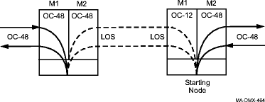
Important! If the circuit pack/port is active for timing and/or transmission, opening the latch or disconnecting fibers causes timing and/or transmission switches. Transmission hits (less than 60 ms) will occur for each separate protection switch. Do not reconnect the optical fibers until instructed to do so. The optical fibers are reconnected after the OC-48 circuit pack/port is backed out at each end of the optical span. Reference: This completes the first phase of the backout at the starting node. The backout at the starting node will be completed after backing out of all the other nodes in the ring. The following figure shows the state of the starting node and the adjacent optical spans. Important! If the original OC-12 port in Main slot M1 at the starting node is equipped with a multirate pluggable transmission module, inc. LOF alarms are reported.  | ||||||||||||||||
9 |
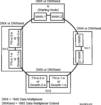
Log in to the adjacent node connected to Main/Function/Growth slot 1. (Refer to the UPSR example at the end of the procedure.) Reference: Procedure 14-2: Connect Personal Computer (PC) and establish WaveStar® CIT session | ||||||||||||||||
10 |
Determine how the node is connected to the UPSR and back out the upgrade at the node.
| ||||||||||||||||
11 |
Except for the starting node, has the upgrade been backed out of all nodes in the UPSR?
| ||||||||||||||||
12 |
Log in to the starting node. (Refer to the UPSR example at the end of the procedure.) Reference: Procedure 14-2: Connect Personal Computer (PC) and establish WaveStar® CIT session | ||||||||||||||||
13 |
Important! The UPD/INIT button does not work during this procedure.
| ||||||||||||||||
14 |
If required, verify the active/standby status of the OC-48 OLIU circuit pack/port in Main slot M2 and perform manual switches to switch traffic away from an active circuit pack/port. Reference: Procedure 12-5.3: Verify active/standby status of circuit pack/port to be backed out | ||||||||||||||||
15 |
Important! If the circuit pack/port is active for timing and/or transmission, opening the latch causes timing and/or transmission switches. Transmission hits (less than 60 ms) will occur for each separate protection switch. Reference: | ||||||||||||||||
16 |
If required at both ends of the optical span to be backed out, perform the following to connect the original OC-12 OLIU circuit pack/port in Main slot M2 and the required OC-12 OLIU circuit pack/port at the opposite end of the original OC-12 optical span:
Result: The inc. OC12 LOS alarms clear. Transmission is now supported on the original OC-12 optical span. Reference: Procedure 14-4: Perform connection and verification of optical facility | ||||||||||||||||
17 |
Important! Perform this step only if the opposite end of the original optical span is an OC-12 port in a Function/Growth group and the Optical Synchronization Source is to be reprovisioned to the original OC-12 port. If required at the opposite end of the original optical span, select Configuration → Timing/Sync to reprovision the Optical Synchronization Source to the original OC-12 port on the OC-12 OLIU circuit pack in slot 1 of the Function/Growth group. Reference: Procedure 6-5: Network Element synchronization provisioning | ||||||||||||||||
18 |
Important! At nodes connected to the UPSR using single-rate circuit packs in the Main slots and multirate circuit packs in the Main/Function/Growth slots, the system reports the ring upgrade mode standing condition (not alarmed) in the NE Alarm List until the node is manually provisioned back to the Normal mode. At nodes connected to the UPSR using single-rate circuit packs in the Main slots and multirate circuit packs in the Main/Function/Growth slots, click the Alarm List button in the top right corner of the System View to view the NE Alarm List and verify that no alarms or standing conditions are present (except ring upgrade mode and ABN condition). Refer to the appropriate trouble-clearing procedures to clear all existing alarms and standing conditions (except ring upgrade mode and ABN condition) before continuing with this procedure. Reference:
| ||||||||||||||||
19 |
Important! This completes the backout procedure, except for taking the nodes connected to the UPSR using the Main slots out of the Ring Upgrade Mode. The decision to take these nodes out of the Ring Upgrade Mode or leave them depends on the reason the back out was necessary, and what is required before again starting the upgrade. In the Ring Upgrade Mode, UPSR cross-connections cannot be created or removed. If required at each node connected to the UPSR using single-rate circuit packs in the Main slots and multirate circuit packs in the Main/Function/Growth slots, select Configuration → Normal Mode. Result: A dialog box appears asking you to confirm changing the NE Mode to Normal mode. Click Yes. The ABN LED is turned off on the SYSCTL circuit pack faceplate and the Ring Upgrade Mode will be removed from the WaveStar® CIT alarm list. End of steps |
UPSR example
