Services overview
Topics in this chapter include:
Overview
A service is a type of communication connection from one place to another. These communication connections have particular attributes and characteristics that are needed to provide a specific communications link through which an information flow or exchange can occur. The 7705 SAR-Hm series of routers support the following services:
Layer 2 Virtual Leased Line (VLL) and BGP virtual private wire services (VPWS)
Layer 2 virtual private LAN services (VPLS) and BGP VPLS services
Layer 3 IP VPN services (VPRN)
serial transport using raw socket and IP transport services
transporting WLAN interface traffic over a service
The service model uses (logical) service entities to construct a service. These logical entities provide a uniform, service-centric configuration and management model for service provisioning (see Nokia service model for more information). Different services can be created on the same node at the same time, and each service is uniquely identified by a service ID.
The supported services provide connectivity between a service access point (SAP) on one node and a SAP on a remote node. A SAP is a logical point where data traffic enters and exits a service. SAPs on the node are associated with Ethernet ports, VLANs, access router interfaces, serial ports, or the WLAN interface.
A connection between two SAPs on the same router is known as a local service. A connection between SAPs on a local and a remote router is known as a distributed service. SAP-to-SAP local services are supported for Ethernet and WLAN-based services. SAP-to-SAP local services are not supported for serial port and raw socket IP transport services.
Distributed services use service destination points (SDPs) to direct traffic from a local router to a remote router through a service tunnel. An SDP is created on the local router and identifies the endpoint of a logical unidirectional service tunnel. Traffic enters the tunnel at the SDP on the local router and exits the tunnel at the remote router. Hence, a service tunnel provides a path from one service router to another. Because an SDP is unidirectional, two service tunnels are needed for bidirectional communication between two service routers (one SDP on each router). The only supported SDP tunnel type is GRE-MPLS tunnels.
SDPs are configured on each participating service router or are auto-bound to the far-end router depending on the requirements and type of service. When configuring SDPs on the source router, the address of the destination router must be specified. When using the auto-bind function for SDPs, configuring individual SDPs between service routers is not required. The node uses BGP advertised information to perform the auto-bind SDP function to the far-end routers. For more information about auto-bind, see SDP binding.
After SDPs are created, they are bound to a specific service, or the service is enabled with auto-bind SDPs, to create a binding to the transport tunnels. In both cases, the SAPs that are part of the service use the bound SDPs as the transport for data traffic between nodes. The binding process is needed to associate the far-end devices to the service; otherwise, far-end devices are not able to participate in the service.
Service types
The 7705 SAR-Hm series of routers offers the following types of services:
-
Virtual Leased Line (VLL) services
-
Ethernet VLL (Epipe)—a PWE3 Ethernet service over MPLS or GRE tunnels for Ethernet frames on 7705 SAR-Hm nodes.
-
-
BGP Virtual Private Wire Services (VPWS)
-
BGP VPWS is a point-to-point Layer 2 VPN service based on RFC 6624 (Layer 2 Virtual Private Networks using BGP for Auto-Discovery and Signaling) which in turn uses the BGP pseudowire signaling concepts from RFC 4761, Virtual Private LAN Services Using BGP for Auto-Discovery and Signaling.
-
-
Internet Enhanced Service (IES)
-
IES is a direct Internet access service where the SAP is assigned an IP interface for routed connectivity.
-
-
Virtual Private LAN Service (VPLS)
-
VPLS provides a Layer 2 multipoint VPN service to end customers. Sites in a VPLS instance appear to be on the same LAN regardless of their location. The 7705 SAR-Hm series nodes can participate in BGP VPLS-based services and traditional T-LDP signaled services.
-
-
Virtual Private Routed Network Service (VPRN)
-
VPRN provides a Layer 3 VPN service to end customers. VPRN services provide MP-BGP peering with other PEs, configurable QoS policy and filtering, and VRF import and export policies.
-
Pseudowire service types lists the supported pseudowire (PW) service types. The values are as defined in RFC 4446.
|
PW service type (Ethertype) |
Value |
|---|---|
|
Ethernet tagged mode |
0x0004 |
|
Ethernet raw |
0x0005 |
Nokia service model
The 7705 SAR-Hm series of routers is deployed at the customer provider edge (PE). Services are provisioned on the router in order to facilitate the transport of communications data across an IP/MPLS network using the Ethernet or wireless interfaces available on the node. The data is formatted so that it can be transported in encapsulation tunnels created using Layer 3 generic routing encapsulation (GRE) MPLS.
The Nokia service model has four main logical components, referred to as (logical) service entities. The entities are: applications, service types, service access points (SAPs), and service destination points (SDPs) (see Service entities). In accordance with the service model, the operator uses the (logical) service entities to construct an end-to-end service. The service entities are designed to provide a uniform, service-centric model for service provisioning. This service-centric design implies the following characteristics.
-
Multiple services can be bound to a single application.
-
Multiple service types can be bound to a single tunnel.
-
Tunnel configurations are independent of the services they carry.
-
Changes are made to a single service entity rather than to multiple ports on multiple devices. It is easier to change one tunnel rather than several services.
-
The operational integrity of a service entity (such as a service tunnel or service endpoint) can be verified by one operation rather than through the verification of dozens of parameters, thereby simplifying management operations, network scalability, and performance.
-
A failure in the network core can be correlated to specific subscribers and services.
-
The following policies are applied to various services:
-
QoS policies
-
filter policies (IP and MAC)
-
Additional properties can be configured for bandwidth assignments and class of service on the appropriate entity.
Service entities
The basic (logical) service entities in the service model used to construct an end-to-end service are:
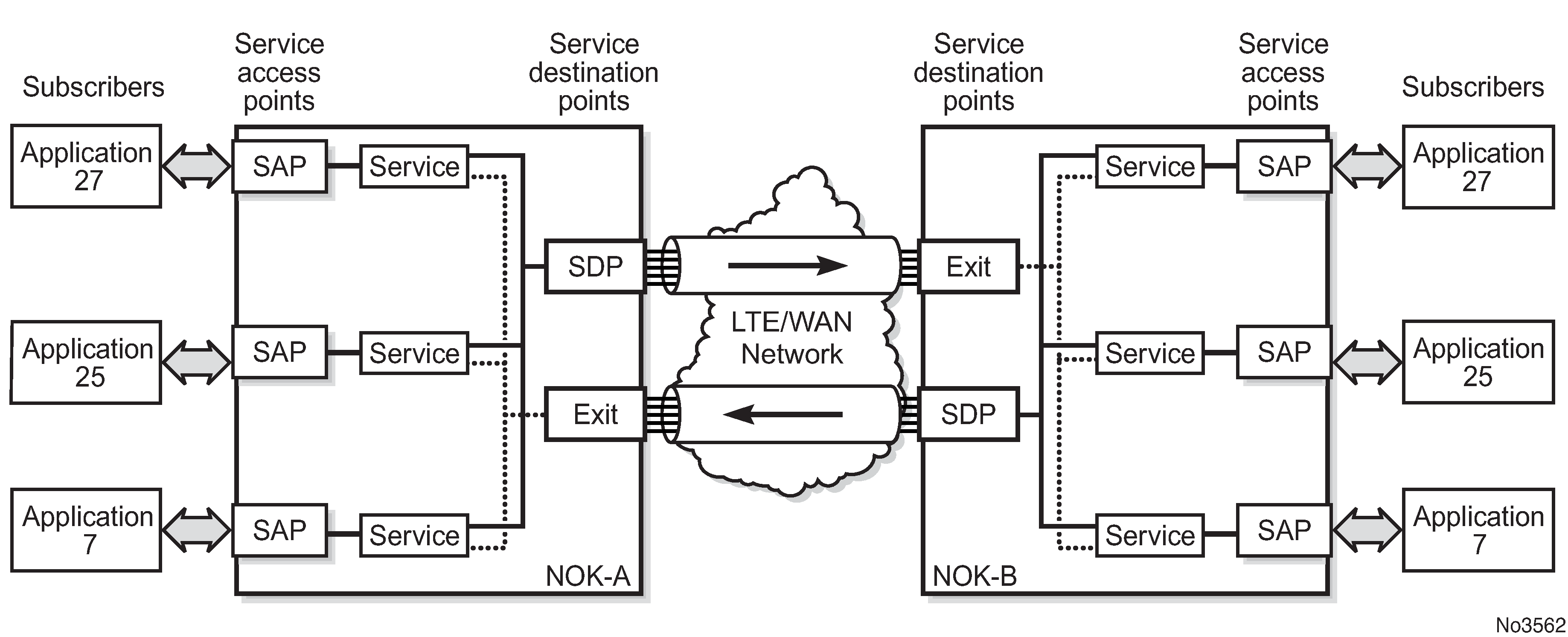
Service entities and the service model shows an example of how the service entities relate to the service model. An application attachment point (for example, an Ethernet port, VLAN, or serial port) connects to a SAP. The SDPs define the entrance and exit points of service tunnels, which carry one-way traffic between the two routers (NOK-A and NOK-B). Configured SDPs are bound to a service or the service is auto-bound which automatically creates tunnels to far-end nodes. The binding of the service to SDPs is the final step in enabling the end-to-end service. In Service entities and the service model, the entrance and exit points are over the wireless interface.
Traffic encapsulation occurs at the SAP and SDP. The 7705 SAR-Hm series supports the following SAP encapsulation types:
-
Ethernet untagged or tagged
-
IP
-
raw serial character data on the serial ports
The 7705 SAR-Hm series supports GRE-MPLS encapsulation for SDPs.
For information about SAP encapsulation types, see SAP encapsulation types and identifiers. For information about SDP encapsulation types, see SDP encapsulation types.
Applications
Every application must have a customer ID, which is assigned when the application service is created. To provision a service, a customer ID must be associated with the service at the time of service creation.
Service types
Service types provide the traffic adaptation needed by customer attachment circuits (ACs). This (logical) service entity adapts customer traffic to service tunnel requirements. A VLL service is a point-to-point MPLS-based emulation service, also called Virtual Private Wire Service (VPWS). The 7705 SAR-Hm series provides Ethernet VLL (Epipe) service and BGP VPLS-based Layer 2 service.
The series also provides Ethernet layer (MAC-based) VPLS service (including management VPLS), raw socket IP transport service, as well as IP layer VPRN and IES services, that offer any-to-any connectivity within a Virtual Routing Domain or Generic Routing Domain, respectively.
Service names
A service ID number must be associated with a service at the time of service creation. When the service is created, an optional service name can be assigned to the service for use by commands that reference the service.
Service access points (SAPs)
Topics in this section include:
A service access point (SAP) is the point at which a service begins (ingress) or ends (egress) and represents the access point associated with a service. A SAP may be a physical port or a logical entity within a physical port. For example, a SAP may be an Ethernet port or a VLAN that is identified by an Ethernet port and a VLAN tag. Each application service connection is configured to use only one SAP.
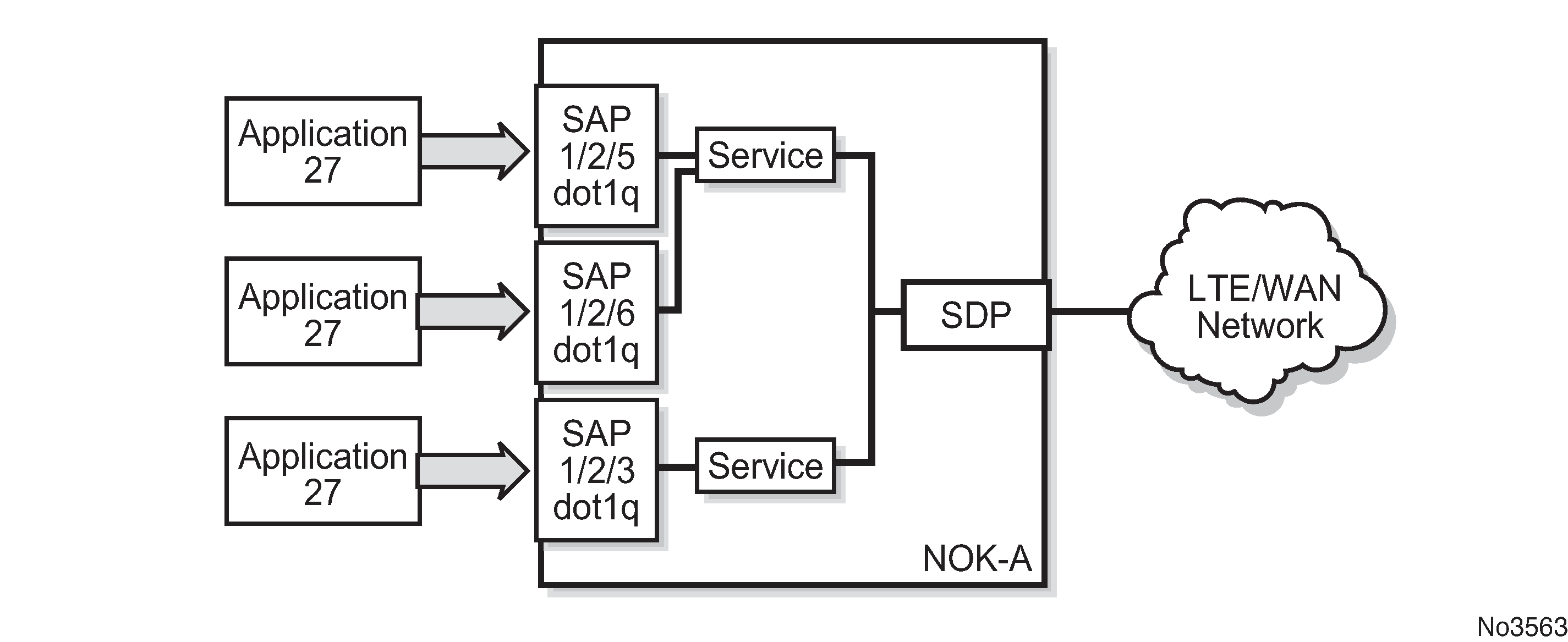
A SAP identifies the application interface point for a service on a service router. Service access point (SAP) shows two applications connected to the same service via two different SAPs. The SAP identifiers are 1/2/5 and 1/2/6, which represent the physical ports associated with these SAPs. The physical port information should be configured before provisioning a service. For more information about configuring a port, see the 7705 SAR-Hm and SAR-Hmc Interface Configuration Guide.
The 7705 SAR-Hm series supports VLL, VPWS, VPLS, and VPRN services. For each service type, the SAP has slightly different parameters; see Layer 2 and Layer 3 services for information.
In general, SAPs are logical endpoints that are local to the node and are uniquely identified by:
the physical Ethernet port
the physical serial port
the encapsulation type for the service
the encapsulation identifier (ID), which is the optional VLAN ID for Epipes
Depending on the encapsulation, a physical port can have more than one SAP associated with it (for example, a port may have several VLANs, where each VLAN has an associated SAP). SAPs can only be created on ports designated as "access" in the physical port configuration.
SAPs cannot be created on ports designated as core-facing "network" ports because these ports have a different set of features enabled in software.
SAP encapsulation types and identifiers
The SAP encapsulation type is an access property of the Ethernet port used for the service. It identifies the protocol that is used to provide the service.
The encapsulation ID for Ethernet ports is an optional suffix that is appended to a port-id to specify a logical sub-element for a SAP. For example, port-id:qtag1 represents a port that can be tagged to use IEEE 802.1Q encapsulation (referred to as dot1q), where each individual tag can identify with an individual service.
Ethernet encapsulations
The following encapsulation service options are available on Ethernet ports:
null—supports a single service on the port; for example, where a single customer with a single service customer edge (CE) device is attached to the port.
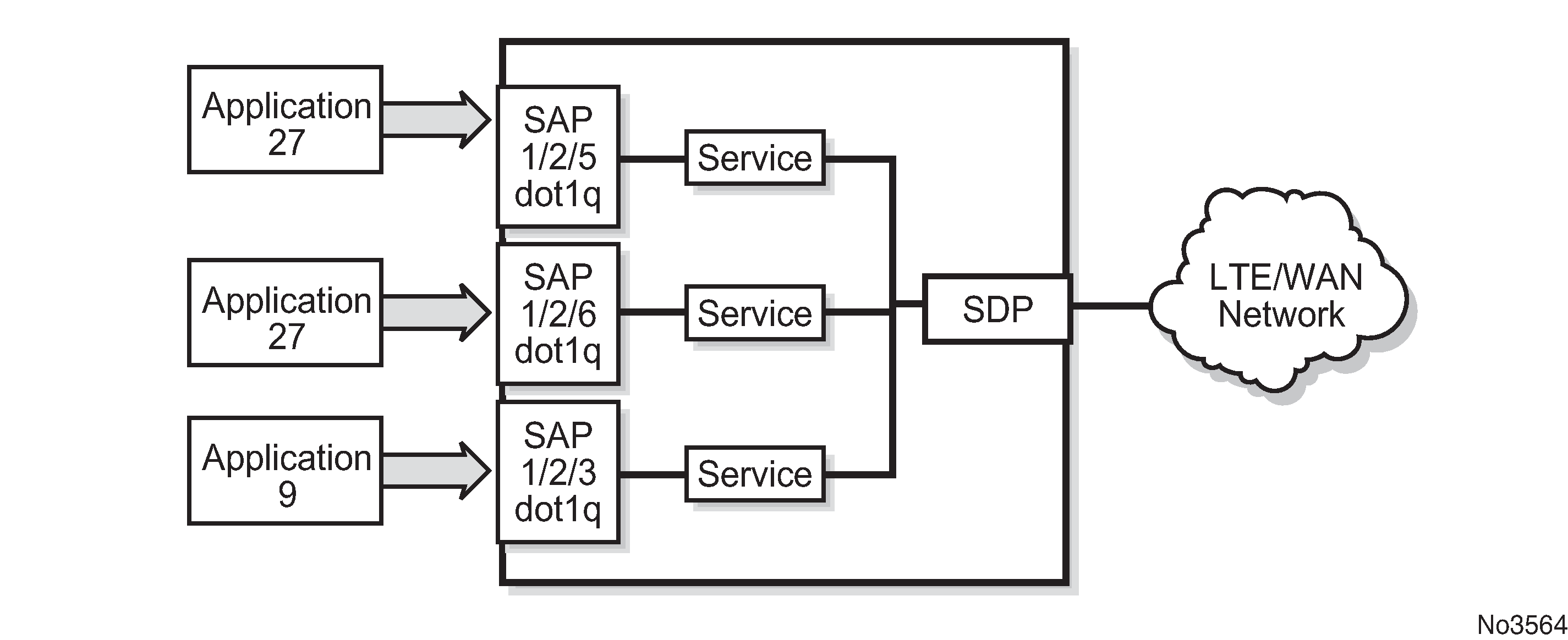
dot1q—supports multiple services for one customer or services for multiple customers (see Multiple SAPs on a single port). For example, dot1q could be used when the Ethernet port is connected to a multi-tenant unit device with multiple downstream customers. The encapsulation ID used to distinguish an individual service is the VLAN ID in the IEEE 802.1Q header.
Default SAP on a dot1q port
The 7705 SAR-Hm series of routers supports default SAP functionality on dot1q- encapsulated ports. On dot1q-encapsulated ports where a default SAP is configured, all packets with Q-tags not matching any other explicitly defined SAPs are assigned to the default SAP for transport. A default SAP is defined in the CLI using the character "*" as a Q-tag, where the "*" means "all".
One of the applications where the default SAP feature can be used is for an access connection of an application that uses the whole port to access Layer 2 services. The internal VLAN tags are transparent to the service. This (the use of a whole port) can be provided by a null-encapsulated port. A dedicated VLAN (not used by the user) can be used to provide management to this application.
In this type of environment, two SAPs logically exist, a management SAP and a service SAP. The management SAP can be created by specifying a VLAN tag that is reserved to manage the application. The service SAP covers all other VLANs and behaves as a SAP on a null-encapsulated port.
There are a few constraints related to the use of a default SAP on a dot1q-encapsulated port:
The default SAP is supported only on VPLS, and Epipe VLL and VPWS services and cannot be created in IES and VPRN services because IES and VPRN services cannot preserve VLAN tag markings.
For VPLS SAPs with STP enabled, STP listens to untagged and null-tagged BPDUs only. All other tagged BPDUs are forwarded like other customer packets. This is the same behavior as null-encapsulated ports.
IGMP snooping is not supported on a default SAP. By not allowing IGMP snooping of a default SAP, all IGMP packets will be transparently forwarded.
The default SAP and the SAP defined by explicit null encapsulation are mutually exclusive (for example, 1/1/1:* and 1/1/1:0 are mutually exclusive). This avoids conflict as to which SAP untagged frames should be associated with.
SAP configuration considerations
In addition to being an entry or exit point for service traffic, a SAP has to be configured for a service and, therefore, has properties. When configuring a SAP, consider the following.
A SAP is a local entity and is only locally unique to a specific device. The same SAP ID value can be used on another service router.
There are no default SAPs. All subscriber service SAPs must be created.
The default administrative state for a SAP at creation time is administratively enabled.
When a SAP is deleted, all configuration parameters for the SAP are also deleted.
A SAP is owned by and associated with the service in which it is created.
An Ethernet port with a dot1q encapsulation type means that the traffic for the SAP is identified based on a specific IEEE 802.1Q VLAN ID value. The VLAN ID is stripped off at SAP ingress and the appropriate VLAN ID is placed on at SAP egress. As a result, VLAN IDs only have local significance, so the VLAN IDs for the SAPs for a service need not be the same at each SAP.
If a port is administratively shut down, all SAPs on that port will be operationally out of service.
A SAP cannot be deleted until it has been administratively disabled (shut down).
Each SAP can have one of the following policies assigned to it:
Ingress QoS policy
Egress QoS policy
Ingress filter policy (for Epipe VLL and VPWS SAPs, VPLS SAPs, VPRN SAPs, IES SAPs, and IES in-band management SAPs)
Egress filter policy (for VPRN and IES SAPs, and for VPLS SAPs (Ethernet SAPs only))
Service Destination Points (SDPs)
Topics in this section include:
An SDP identifies the endpoint of a logical unidirectional service tunnel. The service tunnel provides a path from one service router to another.
In more general terms, SDP refers to the service tunnel itself. The SDP terminates at the far-end router, which is responsible for directing the flow of packets to the correct service egress SAPs on that device.
-
Service Destination Point
-
Service Distribution Point
-
Service Destination Path
-
Service Distribution Path
-
Service Delivery Path
When an SDP is bound to a service, the service is referred to as a distributed service. A distributed service consists of a configuration with at least one SAP on a local node, one SAP on a remote node, and an SDP binding that binds the service to the service tunnel. Multiple SDPs to different far-end nodes are bound to a service to provide transport for SAPs to other nodes participating in that service.
When configured, an SDP has the following characteristics.
-
An SDP is locally unique to a participating service router. The same SDP ID can appear on other service routers.
-
An SDP uses either the system IP address or the cellular PDN interface IP address of the far-end edge router to locate its destination.
-
An SDP is not specific to any one service or to any type of service. When an SDP is created, services are bound to the SDP. An SDP can also have more than one service type associated with it.
-
All services bound to an SDP use the same SDP (transport) encapsulation type defined for the SDP (for example, GRE-MPLS).
-
An SDP is a service entity used for service management. Even though the SDP configuration and the services carried within it are independent, they are related objects. Operations on the SDP affect all the services associated with the SDP. For example, the operational and administrative state of an SDP controls the state of services bound to the SDP.
-
An SDP tunnel from a local device to the far-end device (router) requires a return SDP tunnel from the far end back to the local device. Each device must have an SDP defined for every remote router to which it wants to provide service. The SDP must be created before a distributed service can be configured.
-
An SDP can be used to provide PW redundancy, where up to four spoke SDPs can be assigned to a service endpoint that acts as the managing entity to ensure service connection. For information about pseudowire redundancy, see the 7450 ESS, 7750 SR, 7950 XRS, and VSR Layer 2 Services and EVPN Guide, "Pseudo-wire redundancy".
SDP binding
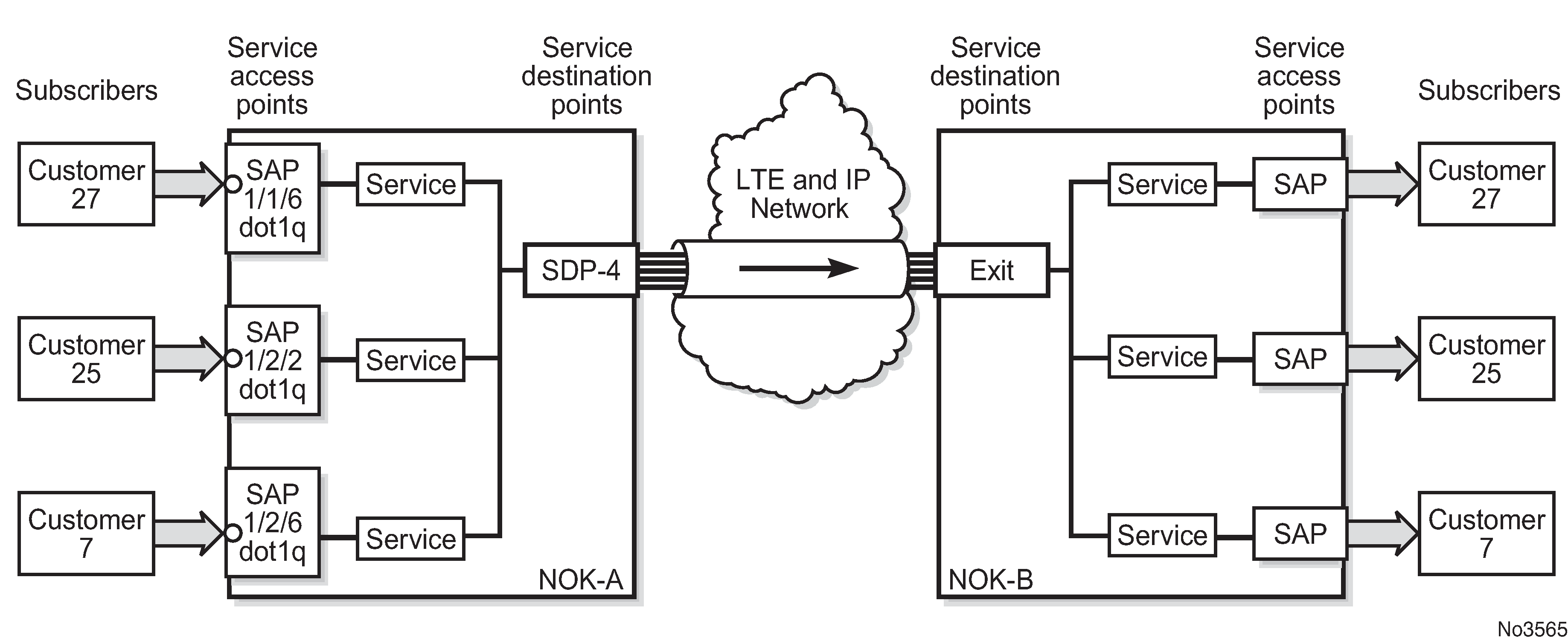
To configure a distributed service pointing from NOK-A to NOK-B, the SDP ID on the NOK-A side (see SDP tunnel pointing from NOK-A to NOK-B) must be specified during service creation in order to bind the service to the tunnel (the SDP). Otherwise, service traffic is not directed to a far-end point and the far-end devices cannot participate in the service (there is no service). To configure a distributed service pointing from NOK-B to NOK-A, a return SDP on the NOK-B side must similarly be specified.
SDP configuration and binding is required for:
Layer 2 services that use T-LDP signaling
Layer 3 services that do not use multi-protocol BGP(MP-BGP) to advertise routes with auto-bind
For Layer 3 VPRN services that use MP-BGP to advertise routes, auto-bind can be configured on the service to automatically bind that service to SDPs with reachability to remote nodes that are participating in MP-BGP.
The VPRN auto-bind function has the following characteristics.
SDPs can be configured while auto-bind is enabled.
Configuring SDPs when auto-bind is enabled is not required to transport VPRN services between nodes participating in the same VPRN.
Configured SDPs have higher precedence and the node will select the configured SDP and its attributes to tunnel traffic to the far-end node.
Auto-bind does not require a return path SDP from a far-end router as long as auto-bind is enabled on that far-end router for the service. If auto-bind is not enabled on the far-end router, then a return path SDP to the local 7705 SAR-Hm series node is required.
For Layer 2 services that use BGP signaling (BGP-VPLS and BGP-VPWS) to exchange label information for the service, auto-gre can be configured on the pseudowire template of the service to automatically bind that service to SDPs with reachability to remote nodes that are participating in the BGP-signaled Layer 2 service. For information about the auto-GRE function available for BGP-VPLS and BGP-VPWS, see the 7450 ESS, 7750 SR, 7950 XRS, and VSR Layer 2 Services and EVPN Guide.
Spoke and mesh SDPs
There are two types of SDPs: spoke and mesh. The type of SDP defines how flooded traffic (or broadcast traffic, such as an ARP request) is propagated. For point-to-point PW/VLL services, spoke SDPs are the only way to bind services to the far-end router. For VPLS, mesh and spoke SDP bindings are allowed.
A spoke SDP that is bound to a service operates like a traditional bridge port. Flooded traffic that is received on the spoke SDP is transmitted to all the spoke SDPs, mesh SDPs, and SAPs to which it is connected. Flooded traffic is not transmitted back toward the port from which it was received.
In contrast, a mesh SDP that is bound to a service operates like a single bridge port. Flooded traffic received on a mesh SDP is transmitted to all spoke SDPs and SAPs to which it is connected. Flooded traffic is not transmitted to any other mesh SDPs or back toward the port from which it was received. This property of mesh SDPs is important for multi-node networks; mesh SDPs are used to prevent the creation of routing loops.
SDP encapsulation types
The Nokia service model uses encapsulation tunnels (also referred to as service tunnels) through the core to interconnect service routers. An SDP is a logical way of referencing the entrance to an encapsulation tunnel.
The 7705 SAR-Hm series supports Layer 2 or Layer 3 services within generic routing encapsulation (GRE-MPLS encapsulation).
An SDP has an implicit maximum transmission unit (MTU) value because services are carried in encapsulation tunnels and an SDP is an entrance to the tunnel. The MTU is configurable (in octets), where the transmitted frame can be no larger than the MTU.
GRE encapsulation
Generic routing encapsulation (GRE) tunnels are used to transport network layer packets over a Layer 3 network such as an LTE or WLAN interface.
GRE-MPLS SDPs are supported on network interfaces.
GRE format
In accordance with RFC 2784, a GRE encapsulated packet has the following format:
delivery header
GRE header
payload packet
Delivery header
The delivery header is always an IPv4 header.
GRE header
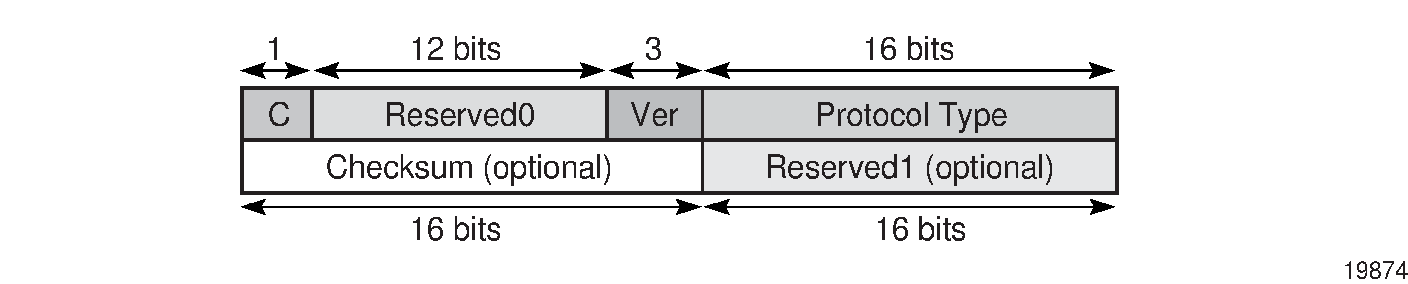
The GRE header format is shown in GRE header and described in GRE header descriptions.
Field |
Description |
|---|---|
C |
Specifies whether there is a checksum in the header If set to 1, both the checksum and reserved1 fields must be present In the network egress (transmit) direction, the C bit is always set to 0; therefore, the checksum and reserved1 fields are omitted from the header. The GRE header is therefore always 4 bytes (32 bits) in the network egress direction. In the network ingress direction, the C bit validity is checked. If it is set to a non-zero value, the GRE packet is discarded and the IP discards counter is increased. |
Reserved0 |
Indicates whether the header contains optional fields The first 5 bits of the field are always set to 0 and bits 6 to 12 are reserved for future use and also set to 0 |
Ver |
Always set to 000 for GRE At network ingress, if a GRE packet is received with the version field set to any value other than 000, the packet is discarded and the IP discards counter is increased |
Protocol type |
Specifies the protocol type of the original payload packet—identical to Ethertype with the only supported option being MPLS unicast (0x8847) |
Checksum (optional) |
Not applicable |
Reserved1 (optional) |
Not applicable |
Payload packet
The payload encapsulation format depends on the type of service that is being carried over GRE-MPLS. The payload encapsulation format for GRE services is shown in GRE service payload packet over Ethernet and described in GRE service payload packet descriptions.

Field |
Description |
|---|---|
Eth |
The Layer 2 transport header The only Layer 2 protocol supported is Ethernet MTU size depends on the encapsulation type (14 bytes for null encapsulation and 18 bytes for dot1q encapsulation) The Ethertype is always set to IP (0x800) |
IP |
Indicates the transport protocol IPv4 is the transport protocol for GRE-MPLS |
GRE |
Indicates the encapsulation protocol |
MPLS service header |
The MPLS service label identifies the service and the specific service element being transported For VLL and VPWS services, the label references the pseudowire that was statically configured, or signaled via T-LDP or BGP signaling For VPLS services, the label references a particular VPLS pseudowire that was signaled via T-LDP or BGP signaling to allow the end-to-end VPLS service For VPRN services, the label references either a spoke SDP pseudowire associated with the VPRN, or an MP-BGP advertised route that has been signaled via BGP to allow the end-to-end VPRN service |
CW for VLL and VPWS |
The pseudowire Control word (CW) is a 32-bit (4-byte) field that is inserted between the VC label and the Layer 2 frame For more information about the Control word, see "Pseudo-wire Control word" in the 7450 ESS, 7750 SR, 7950 XRS, and VSR Layer 2 Services and EVPN Guide. |
Services payload |
The services payload is the payload of the service being encapsulated For VLL, VPWS, and VPLS, this is a Layer 2 frame with either null or with dot.1q encapsulation For VPRN, this is a Layer 3 IPv4 or IPv6 packet without Layer 2 information |
At network egress over a cellular port, the destination IP address of the GRE-MPLS IP header is always the far-end IP address that was either configured for the SDP, or learned through BGP routing. If the far-end address is for a cellular port on another 7705 SAR-Hm series node, then that address could be either the system IP address or the cellular PDN interface IP address, depending on the mode of operation deployed at that far-end location. The source IP address of the GRE-MPLS IP header is always set to the cellular PDN interface IP address. This address may be statically configured or dynamically assigned to a cellular port. For information about the PDN router interface modes of operation and how the PDN router interface IP address is assigned, see PDN router interfaces.
At the cellular port network ingress, the destination IP address in the IP header is the same as the cellular PDN interface IP address, because this IP address is the only address reachable over the LTE network. The source IP address of the IP header matches the far-end IP address associated with the GRE-MPLS tunnel. If the packet originates from another cellular port over the cellular network, the source IP address matches the cellular IP address used by the remote node. If the packet originates from another node that is Ethernet connected, then the source IP address is typically the system IP address of those nodes.
At network egress over an Ethernet interface, the source IP address is always set to the node system IP address; the destination IP address is set to one of the following:
the system IP address of the service router on which the GRE SDP is configured
the far-end interface address
a loopback address
GRE SDP tunnel fragmentation and reassembly
It is possible to transport services over GRE-MPLS tunnels when the service MTU is larger than the cellular interface MTU. This requires the GRE-MPLS packets to be fragmented and reassembled using GRE SDP fragmentation and reassembly operations. For information, see the 7450 ESS, 7750 SR, 7950 XRS, and VSR Services Overview Guide, "GRE SDP tunnel fragmentation and reassembly".
GRE SDP termination on router interface IP address
In some applications, an Ethernet interface is required to operate as a network interface and originate and terminate GRE-MPLS packets. If the application requires that GRE-MPLS packets terminate on the interface IP address instead of on the system IP address, then GRE SDP termination on the router interface IP address functionality is available. For information, see the 7450 ESS, 7750 SR, 7950 XRS, and VSR Services Overview Guide, "GRE SDP termination on router interface IP address".
SDP ping
For general information about SDP ping support, see the 7450 ESS, 7750 SR, 7950 XRS, and VSR OAM and Diagnostics Guide, "SDP ping".
Services over the cellular PDN interface
When configuring services to and from the node over the cellular PDN interface, the following points should be considered:
-
The mode of operation that is required for the cellular PDN interface, either static cellular system IPv4, static cellular interface IPv4, dynamic cellular interface IPv4, static cellular interface IPv6, or dynamic cellular interface IPv6. See PDN router interfaces for information about each mode of operation.
-
The service type that is required; for example, a VLL, VPLS, or VPRN. See Layer 2 and Layer 3 services for information about supported service types.
-
The signaling type that is required, either T-LDP, BGP, or both. See MPLS and Router configuration for information about configuring signaling and routing.
-
The routing and reachability of the node for each configured service type when the node is operating with two SIMs. For information about dual SIM deployment, see the 7705 SAR-Hm and SAR-Hmc Interface Configuration Guide, "Dual SIM Deployment".
The combinations of points from the list above will result in different configuration requirements when enabling services over a cellular port.
The mode of operation of the cellular port for each enabled SIM is the main consideration when enabling services over cellular. IPv4 modes of operation on the cellular PDN interface shows an example of the IPv4 modes of operation. The points to consider for enabling services over cellular for each mode of operation are described below.
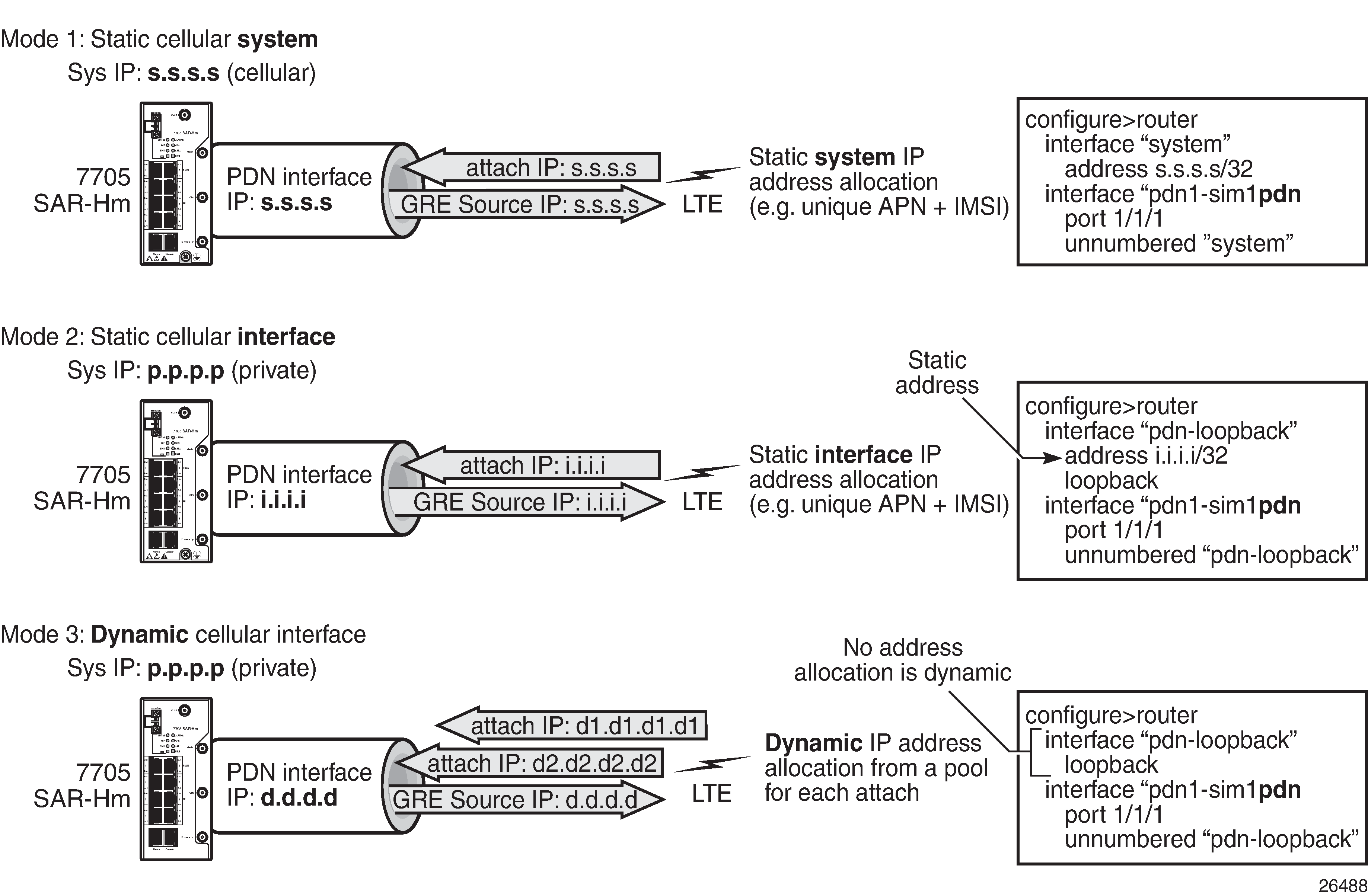
Static cellular system IPv4 mode
When a PDN router interface is configured for static cellular system IPv4 mode, consider the following points when setting up a service over a PDN router interface and its associated cellular port:
The system IP address used to manage the node is the same as the cellular PDN interface IP address that gets assigned during the cellular attachment procedure.
SDPs that are destined for the local node from other nodes must be configured to use the system IP address (identical to the cellular IP address) of the local node as the far-end address.
T-LDP signaling sessions from the local node to peers use the system IP address as the local address for these sessions. This is the default behavior of the SR OS. The T-LDP sessions from peer nodes to the local node must be established to the system IP address.
BGP sessions from the local node to peers where BGP VPWS, BGP VPLS, MP-BGP, or BGP routing is required for services use the system IP address as the local address for sessions. This is the default behavior of the SR OS. BGP sessions from peer nodes to the local node must be established to the system IP address.
Static cellular system IPv4 mode supports all service types.
In a dual SIM deployment, static cellular system IPv4 mode requires that the same IP address be allocated for both SIMs. The single system IP address allocation depends on this requirement being met. This requirement can be challenging to meet in most deployment models. Static cellular interface IP mode or dynamic cellular interface IP mode should be considered when dual SIM is required, as these modes allow different IP addresses to be allocated for each SIM.
Static cellular interface IPv4 mode
When a PDN router interface is configured for static cellular interface IPv4 mode, consider the following points when setting up a service over a PDN router interface and its associated cellular port:
The system IP address used to manage the node is not the same as one of the cellular PDN interface IP addresses assigned during the cellular attachment procedure.
SDPs that are destined for the local node from other nodes must be configured to use the PDN interface IP address of the local node as the far-end address. They must not use the system IP address of the local node as the far-end address.
T-LDP signaling sessions from the local node to peers must use the PDN interface IP address as the source IP address for these sessions; otherwise, GRE-MPLS services will not function properly. Operators must use the local-lsr-id LDP command to specify that the PDN router interface address is the local LSR ID on this 7705 SAR-Hm for these T-LDP sessions. For information about configuring the local-lsr-id command, see the 7450 ESS, 7750 SR, 7950 XRS, and VSR Classic CLI Command Reference Guide. When the local-lsr-id is configured, T-LDP sets the source IP address of session packets to the PDN interface IP address.
BGP sessions from the local node to peers where BGP VPWS, BGP VPLS, MP-BGP, and BGP routing is required for services must use the PDN interface IP address as the source IP address for these sessions. If these sessions do not use the PDN interface IP address as the source IP address, then GRE-MPLS services that require BGP-advertised information will not function properly.
Operators must configure the BGP local-address command to specify that the PDN router interface is the local address on the local 7705 SAR-Hm series node for these BGP sessions. For information about configuring the BGP local address, see Using a router interface address as the BGP local address. When the local-address is configured, BGP sets the source IP address of session packets to the PDN interface IP address.
Static cellular interface IPv4 mode supports all service types.
When dual SIM operation is required, the points listed above must be considered for each PDN router interface configured for each SIM.
Dynamic cellular interface IPv4 mode
When a PDN router interface is configured for dynamic cellular interface IPv4 mode, consider the following points when setting up a service a over PDN router interface and its associated cellular port:
The system IP address used to manage the node is not the same as the cellular PDN interface IP address assigned during the cellular attachment procedure.
The PDN interface IP address changes every time the PDN reattaches to the cellular network
SDP configurations cannot be made from other nodes to the local node. The changing IP address of the PDN interface during each PDN attachment procedure inhibits the static configuration needed to manually configure SDPs.
T-LDP signaling sessions cannot be established toward the local node because the changing PDN interface IP address inhibits the static configuration of T-LDP sessions toward the PDN interface.
BGP sessions cannot be established toward the local node because the changing PDN interface IP address inhibits the static configuration of BGP sessions toward the PDN interface.
BGP sessions from the local node to peers where MP-BGP and BGP routing is required for services must use the PDN interface IP address as the source IP address for these sessions. Operators must specify the loopback interface of the PDN router interface when configuring the BGP local-address command. For information about configuring the BGP local address, see Using a router interface address as the BGP local address. When the local-address command is configured with the loopback interface of the PDN router interface, BGP sets the source IP address of session packets to the PDN interface IP address.
BGP far-end peering nodes to the local node must be configured with the dynamic-neighbor command using an IP address range that matches the possible PDN router interface attachment IP addresses on the local node. This allows the PDN interface IP address to dynamically change and re-establish BGP sessions to the same far-end peering node. For information about the dynamic-neighbor command, see the 7450 ESS, 7750 SR, 7950 XRS, and VSR Classic CLI Command Reference Guide.
Only services that use auto-bind or auto-gre-sdp can operate with dynamic cellular interface IP mode. The 7705 SAR-Hm series supports MP-BGP-based VPRN services with auto-bind, and BGP-VPLS and BGP-VPWS with auto-gre-sdp.
Dynamic cellular interface IP mode does not support the following services:
Layer 2 services that use T-LDP signaling
Layer 3 services that do not use auto-bind
When dual SIM operation is required, the points listed above must be considered for each PDN router interface configured for each SIM.
Static cellular interface IPv6 mode
When a PDN router interface is configured for static cellular interface IPv6 mode, consider the following points when setting up a service over a PDN router interface and its associated cellular port:
GRE-MPLS based services are not supported with static cellular interface IPv6 mode.
Services that are supported using IPSec secure interfaces are supported with static cellular interface IPv6 mode.
In a dual SIM deployment, the points listed above must be considered for each PDN router interface configured for each SIM.
Dynamic cellular interface IPv6 mode
When a PDN router interface is configured for dynamic cellular interface IPv6 mode, consider the following points when setting up a service over a PDN router interface and its associated cellular port:
-
GRE-MPLS based services are not supported with dynamic cellular interface IPv6 mode.
-
Services that are supported using IPSec secure interfaces are supported with dynamic cellular interface IPv6 mode.
In a dual SIM deployment, the points listed above must be considered for each PDN router interface configured for each SIM.
Services over Ethernet with DHCP client
When configuring services over an Ethernet-based router interface that is enabled as a DHCP client, the IP address is dynamically allocated by the DHCP server that the DHCP client communicates with. See DHCP client and Router interface command reference for information about configuring the DHCP client on a router interface.
The IP address allocated by the DHCP server may not be the same address each time the DHCP client issues a DHCP discovery or request message. In any case, the value of the address is not typically known and establishing services over the interface needs to account for this discovered IP address.
Consider the following points when setting up a service over an Ethernet-based router interface.
SDP configurations cannot be made from other nodes to the local node. The potentially changing and unknown IP address inhibits the static configuration that is needed to manually configure SDPs.
T-LDP signaling sessions cannot be established toward the local node because the potentially changing and unknown IP address inhibits the static configuration of T-LDP sessions toward the interface.
BGP sessions cannot be established toward the local node because the potentially changing and unknown IP address inhibits the static configuration of BGP sessions toward the interface.
BGP sessions from the local node to peers where MP-BGP and BGP routing is required for services must use the DHCP client IP address as the source IP address for these sessions. Operators must use the router interface name when configuring the BGP local address. For information about configuring the BGP local address, see Using a router interface address as the BGP local address. When the local-address command is configured with the DHCP client interface, BGP sets the source IP address of session packets to the IP address learned by the DHCP client from the DHCP server.
BGP far-end peering nodes to the local node must be configured with the dynamic-neighbor command using an IP address range that matches the possible DHCP client addresses on the local node. This allows the IP address assigned by the DHCP server to the DHCP client to dynamically change and re-establish BGP sessions to the same far-end peering node. For information about the dynamic-neighbor command, see the 7450 ESS, 7750 SR, 7950 XRS, and VSR Classic CLI Command Reference Guide.
Only services that use auto-bind or auto-gre-sdp can operate over a router interface enabled as a DHCP client. The 7705 SAR-Hm series supports MP-BGP-based VPRN services with auto-bind and BGP-VPLS and BGP-VPWS with auto-gre-sdp.
Router interfaces that are enabled as DHCP clients enabled do not support the following services:
Layer 2 services that use T-LDP signaling
Layer 3 services that do not use auto-bind
Services with the WLAN interface
The WLAN interface can be configured as either an access point (AP) or as a station. For information about the AP and station and how to configure them, see the 7705 SAR-Hm and SAR-Hmc Interface Configuration Guide .
When configured as an AP, the WLAN interface provides SAP-level connectivity to the traffic it sends and receives over the interface from devices that are connected to it. The WLAN AP traffic can be transported over a service to remote locations; for example, to a remote WLAN gateway.
When configured as a station, the WLAN interface operates as a network interface to transport services over WLAN toward a remote AP. The node uses GRE-MPLS encapsulated SDPs to provide Layer 3 transport over the WLAN station interface.
Transporting WLAN access point traffic over services
The WLAN interface can be used as an access point to provide connectivity to other devices. As an access point, the WLAN interface brings device traffic into a service SAP, which is then carried over an SDP and ultimately over a network WAN interface such as an Ethernet port or a cellular port. The port ID of the WLAN interface is used as the SAP ID that binds the WLAN interface to the service. For information about configuring the WLAN MDA and WLAN port parameters to enable the WLAN interface, see the 7705 SAR-Hm and SAR-Hmc Interface Configuration Guide.
To provide services from the WLAN AP to other nodes and devices in the network, a Layer 2 Epipe service is required. The Epipe either connects the WLAN AP to the Nokia WLAN gateway (WLAN-GW) enabled on the VSR or 7750 SR, or back hauls the WLAN AP traffic to other nodes in the network. For information about configuring the WLAN-GW, see the 7450 ESS, 7750 SR, and VSR Triple Play Service Delivery Architecture Guide .
WLAN clients can be optionally authenticated by an AAA server before being allowed access to the WLAN AP and before their traffic can be carried over the transport service.
Layer 2 Epipe service to the WLAN-GW
The WLAN interface AP can connect directly to the WLAN Gateway (WLAN-GW) over a Layer 2 Epipe service. For information about the WLAN-GW, see the 7450 ESS, 7750 SR, and VSR Triple Play Service Delivery Architecture Guide, "WiFi aggregation and offload".
Using an Epipe to connect a WLAN AP to a WLAN-GW illustrates the use of an Epipe service to connect the WLAN AP on a 7705 SAR-Hm to the WLAN-GW.
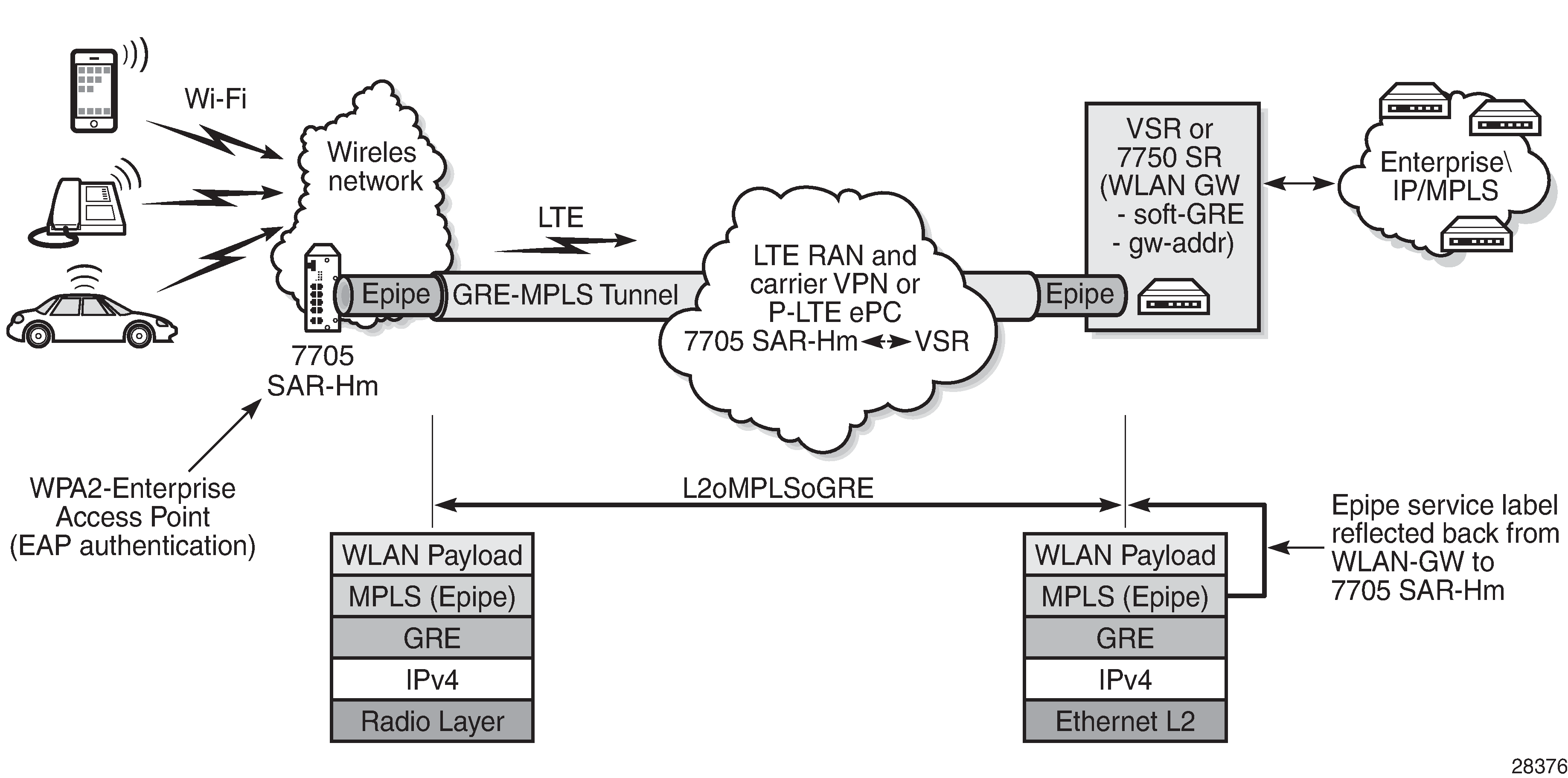
In Using an Epipe to connect a WLAN AP to a WLAN-GW , to connect to the WLAN-GW, the WLAN interface AP port ID must be configured as the L2 SAP of an Epipe service. The Epipe service is configured with a spoke SDP where the far-end address of the SDP (GRE) is configured to reach the gateway address of the WLAN-GW.
There is no signaling required to establish the Epipe service because a static ingress and egress VC label must be configured with the same value. The VC label received by the WLAN-GW from the WLAN AP node (the egress VC label) is reflected back from the WLAN-GW for traffic destined for the WLAN AP node. The 7705 SAR-Hm uses the received VC label (the ingress VC label) to determine that the received traffic is for the Epipe service associated with the WLAN AP SAP.
If the same SSID is used for multiple WLAN APs in the network (for example, an enterprise SSID for a campus-wide WLAN network), the same VC label should be used for each WLAN AP Epipe participating in the same SSID network WLAN service. Using a unique VC label per SSID allows WLAN clients connecting to the SSID to roam between WLAN APs that are broadcasting the same SSID.
The following output shows a configuration example of the SDP and Epipe SAP.
A:ALA-1>config>service# info
----------------------------------------------
...
    epipe 5500 customer 5 vpn 5500 create
        description "WLAN AP mySSIDname to WLAN GW"
        sap 1/4/1 create
            no shutdown
        exit
        spoke-sdp 1:123 create
            description "SDP 1 binding to WLAN GW gw-address"
            ingress
                vc-label 5500
            exit
            egress
                vc-label 5500
            exit
        exit
        no shutdown
    exit
The WLAN AP authenticates users before forwarding their traffic over the Epipe. See the 7705 SAR-Hm and SAR-Hmc Interface Configuration Guide for information about security parameters and supported authentication protocols.
DHCP snooping and DHCP relay must be enabled on the WLAN AP so that attached clients can successfully acquire an IP address from the WLAN GW when they issue DHCP requests. The WLAN AP snoops for DHCP requests and modifies them to include DHCP option 82, specifically the circuit ID sub-option that includes the MAC address of the AP, the SSID of the AP, and the SSID type of either open or secured. The DHCP request is then relayed to the WLAN GW over the Epipe service. To enable DHCP snooping and DHCP relay on the WLAN port, the command config>port>wlan>access-point>dhcp>no shutdown must be executed in the CLI. For more information, see the 7705 SAR-Hm and SAR-Hmc Interface Configuration Guide.
Services over the WLAN station port
The WLAN station port provides network-level connectivity to a WLAN AP to provide end-to-end services between the node and another Nokia router. A network interface configured on the WLAN station acts in a similar fashion to network interfaces configured on Ethernet ports. BGP routing and GRE-MPLS-based SDPs can traverse the network interface on the WLAN station port. The remote AP that the WLAN station port connects to must provide the necessary reachability to another Nokia router that can terminate the services from the node.
Services transport over the WLAN station port illustrates how the WLAN station port connected to an AP can provide end-to-end services between the node and another Nokia router.
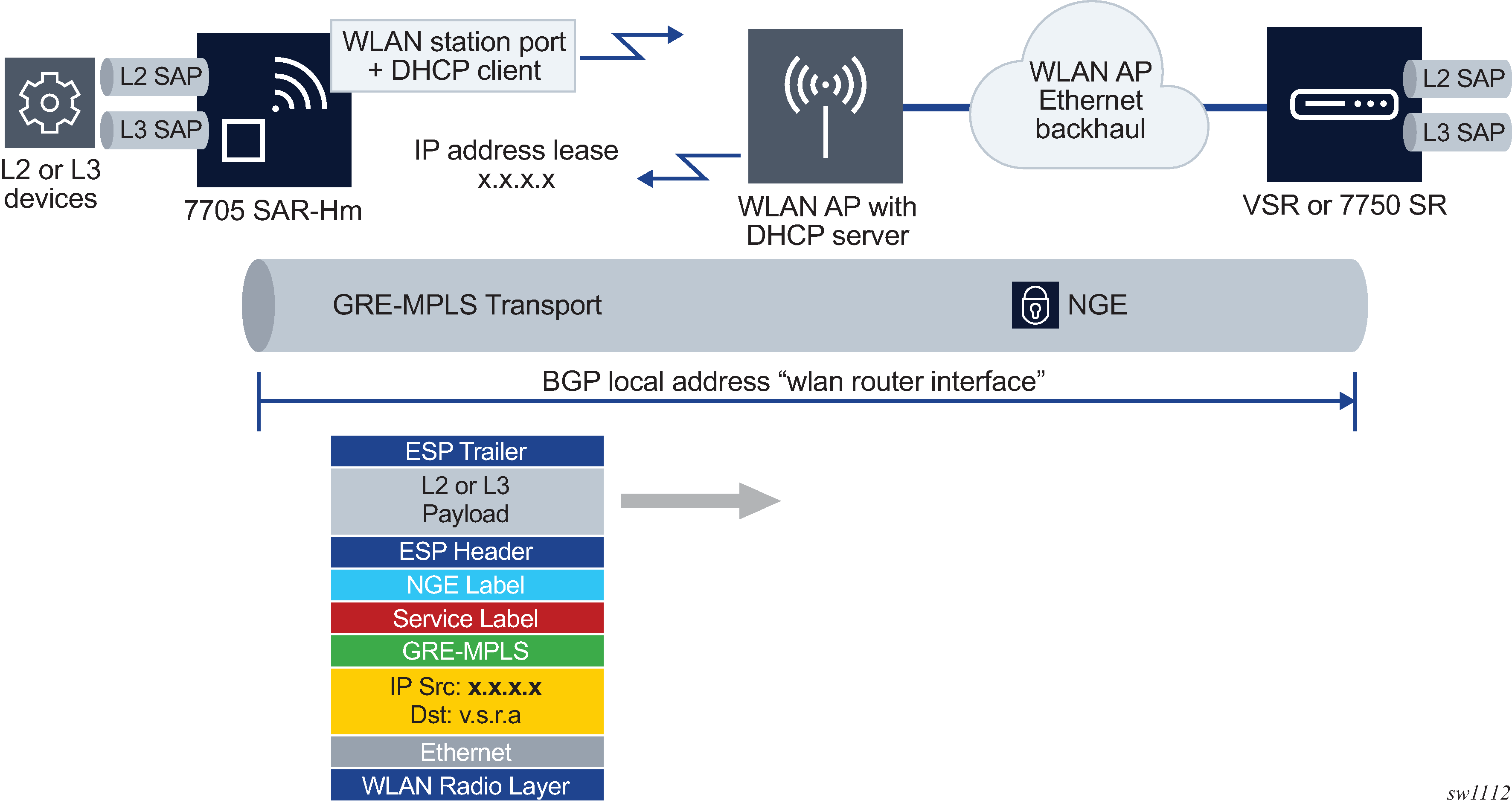
When configuring services over the WLAN station port, the router interface IP address can be configured manually on the router interface or it can be automatically discovered by the DHCP client configured on the router interface.
When the IP address is configured manually, services are established using standard methods to set up services over Ethernet ports because the WLAN station operates as a standard Ethernet port when it is operationally up.
For information about an automatically discovered IP addresses using the DHCP client, see Services over Ethernet with DHCP client.
Stitching services between the cellular interface and a WLAN AP
When extending IP/MPLS services over WLAN from the cellular interface, services can be stitched together from the cellular interface to the WLAN AP interface. Service stitching allows operators to create a hub-and-spoke topology from the stitching node to other WLAN stations over the WLAN AP using the same WLAN network.
Stitching services from a cellular interface to a WLAN AP is an example of stitching services from a cellular interface to the WLAN AP.
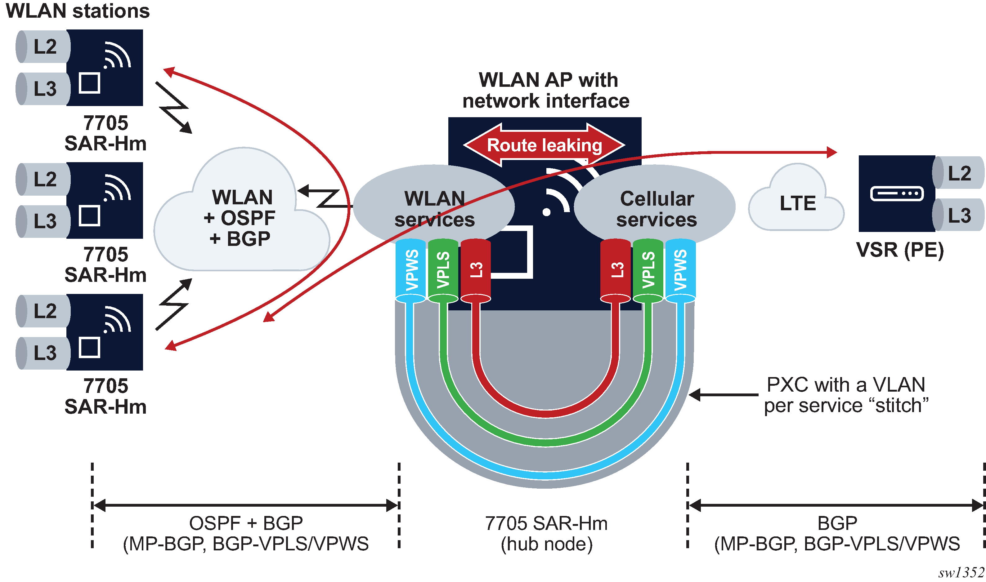
With a hub-and-spoke WLAN topology, Layer 2 or Layer 3 services can be established between the WLAN stations over the same WLAN network. An OSPF and BGP control plane is configured over the WLAN network from each station to the AP, so that each WLAN station learns routing information from the other stations or from the WLAN AP. The control plane also distributes routing information learned from the cellular interface allowing WLAN stations to learn routes to PE nodes reachable over the cellular interface.
When services from a station need to reach a destination over the cellular interface, the services must terminate on the PXC port of the hub 7705 SAR-Hm. The other end of the PXC port then re-originates the traffic over a dedicated service over the cellular interface toward other PEs reachable over the cellular interface.
For Layer 3 VPRN services, routes need to be leaked from the WLAN-side VPRN to the cellular-side VPRN. For VPLS, MAC addresses are learned across the PXC port as needed and re-advertised in BGP-VPLS. For VPWS, the stitch is achieved by extending the Epipe service from WLAN to over cellular.
Daisy chaining
When stitching services between the cellular interface and the WLAN interface, it is possible to create a daisy chain topology; see Daisy chain topology for stitched services.
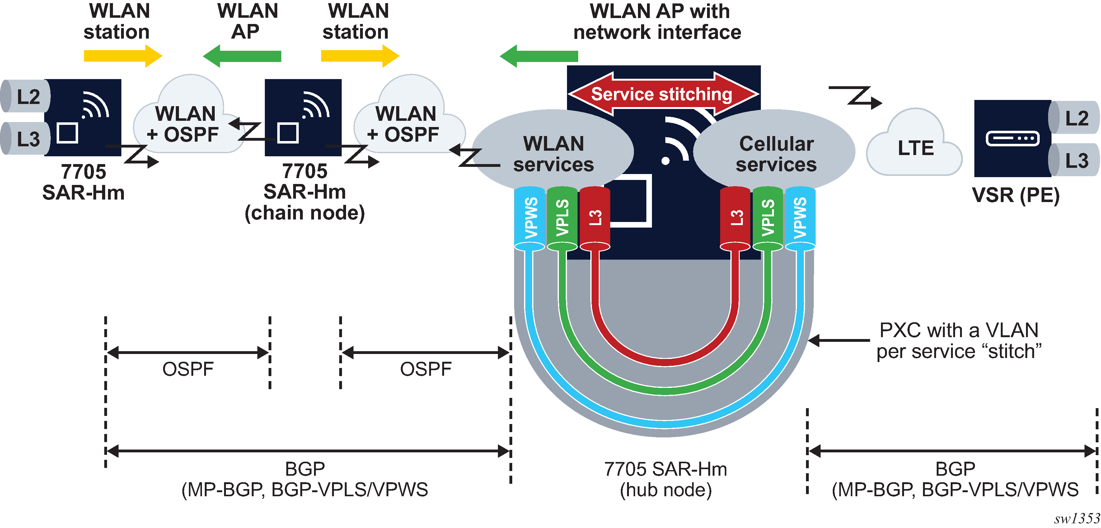
In a daisy chain topology, a hub node is configured as described in section Stitching services between the cellular interface and a WLAN AP and a chain node is introduced to further extend the WLAN network by creating multiple hops between the hub node and the last node in the chain. The OSPF control plane is configured on all WLAN interfaces and BGP is configured from the hub node to the last node in the chain. If services terminate on the chain node, a BGP session is configured between the chain node and the hub node.