Ethernet Virtual Private Networks
This chapter provides an overview and configuration information about Ethernet Virtual Private Networks (EVPNs).
Topics in this chapter include:
Overview and EVPN Applications
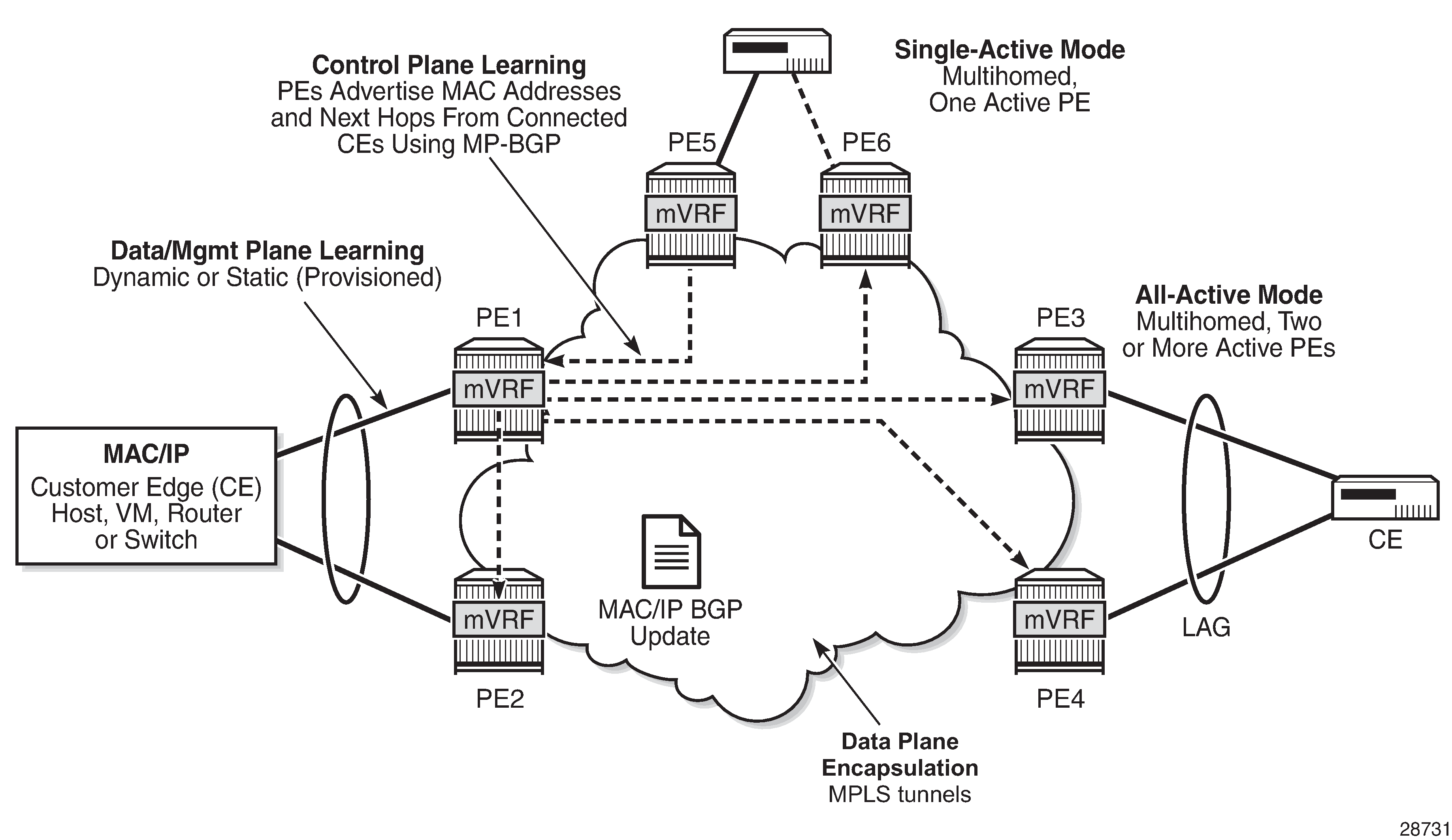
EVPN is an IETF technology as defined in RFC 7432, BGP MPLS-Based Ethernet VPN, that uses a new BGP address family and allows VPLS services to be operated as IP-VPNs, where the MAC addresses and the information to set up the flooding trees are distributed by BGP.
EVPN is designed to fill the gaps in other Layer 2 VPN technologies such as VPLS. The main objective of EVPN is to build Ethernet LAN (E-LAN) services similar to RFC 4364 IP-VPNs while supporting MAC address learning in the control plane (distributed by MP-BGP), efficient multi-destination traffic delivery, and active-active multihoming.
EVPN can be used as the control plane for different data plane encapsulations. The 7705 SAR implementation supports the following data plane encapsulation:
EVPN for MPLS tunnels (EVPN-MPLS)
In EVPN-MPLS, PEs are connected by any type of MPLS tunnel. Typically, EVPN-MPLS is used as an evolutionary step for VPLS services in the WAN, with Data Center Interconnect being one of the main applications.
EVPN for MPLS Tunnels in E-LAN Services
EVPN for MPLS in VPLS Services shows the use of EVPN for MPLS tunnels on the 7705 SAR. In this example, EVPN is used as the control plane for E-LAN services in the WAN.
EVPN-MPLS is standardized in RFC 7432 as a Layer 2 VPN technology that can fill the gaps in VPLS for E-LAN services. A significant number of service providers offering E-LAN services today require EVPN for its multihoming capabilities as well as for the optimization that EVPN provides. EVPN supports all-active multihoming and single-active multihoming.
Although VPLS already supports single-active multihoming, EVPN single-active multihoming is considered to be a superior technology due to its mass-withdrawal capabilities to speed up convergence in scaled environments.
EVPN technology provides significant benefits, including:
superior multihoming capabilities
IP-VPN-like operation and control for E-LAN services
reduction and (in some cases) suppression of the BMU (broadcast, multicast, and unknown unicast) traffic in the network
simple provisioning and management
new set of tools to control the distribution of MAC addresses and ARP entries in the network
EVPN for MPLS Tunnels in E-Line Services
The MPLS network used by EVPN for E-LAN services can also be shared by Ethernet line (E-Line) services using EVPN in the control plane. EVPN for E-Line services (EVPN-VPWS, virtual private wire service) is a simplification of the RFC 7432 procedure, and is supported on the 7705 SAR in compliance with IETF draft-ietf-bess-evpn-vpws.
EVPN for MPLS Tunnels
This section provides information about EVPN for MPLS tunnels:
BGP-EVPN Control Plane for MPLS Tunnels
EVPN Route Types and Usage lists the EVPN route types supported on the 7705 SAR and their use in EVPN-MPLS.
EVPN Route Type |
Use |
|---|---|
Type 1 – Ethernet Auto-Discovery route |
Mass-withdrawal, Ethernet segment identifier (ESI) labels, aliasing |
Type 2 – MAC/IP Advertisement route |
MAC/IP advertisement, IP advertisement for ARP resolution |
Type 3 – Inclusive Multicast Ethernet Tag route |
Flooding tree setup (BMU flooding) |
Type 4 – Ethernet Segment (ES) route |
ES discovery and DF election |
Type 5 – IP Prefix Advertisement route |
IP routing |
If EVPN multihoming is not required, two route types are needed to set up a basic EVPN instance (EVI) (see EVPN-MPLS Route Type 2 and Type 3 (Required Routes and Communities)):
If multihoming is required, two additional route types are needed (see EVPN Route Type 1 and Type 4 ):
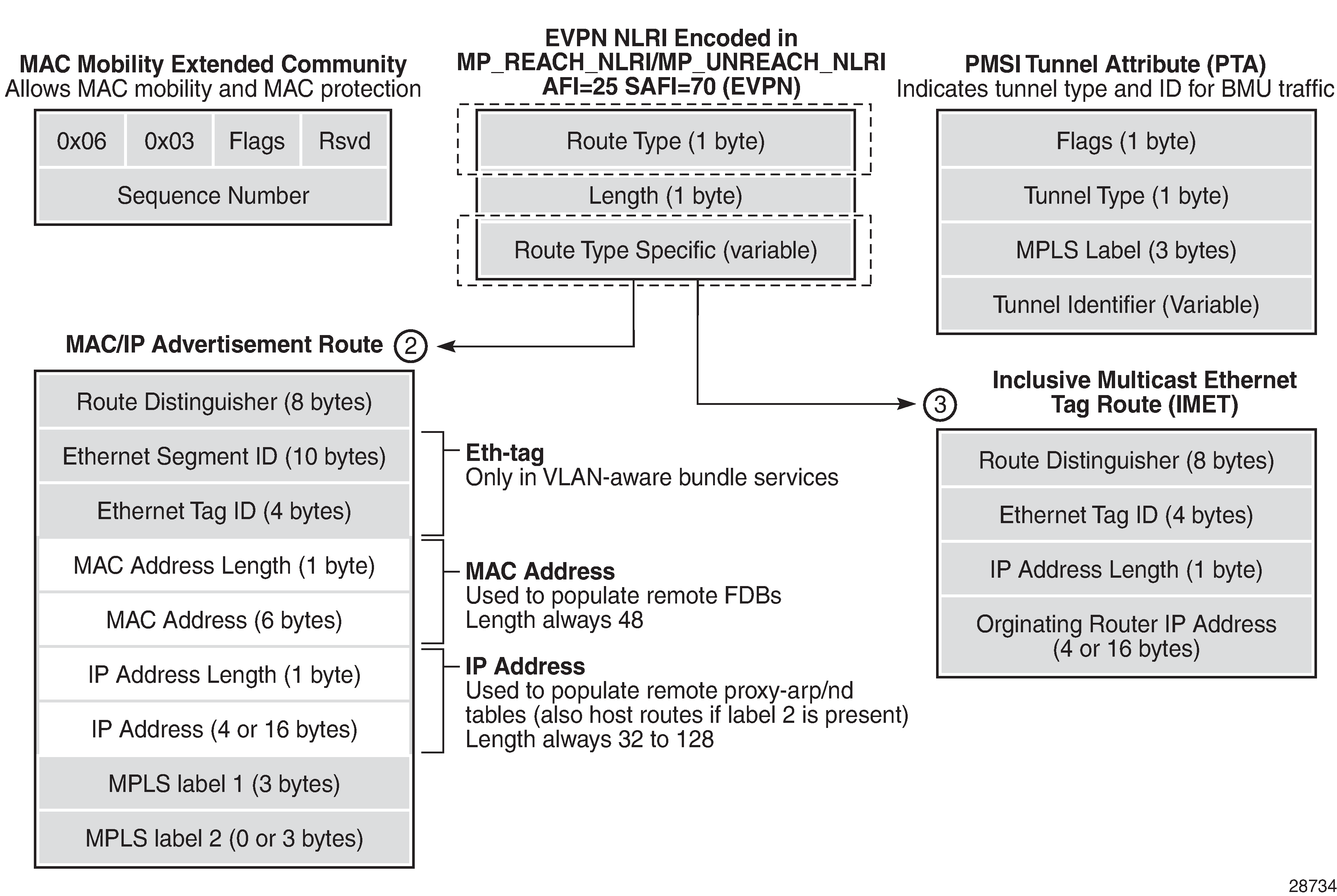
The route fields and extended communities for route types 2 and 3 are shown in EVPN-MPLS Route Type 2 and Type 3 (Required Routes and Communities).
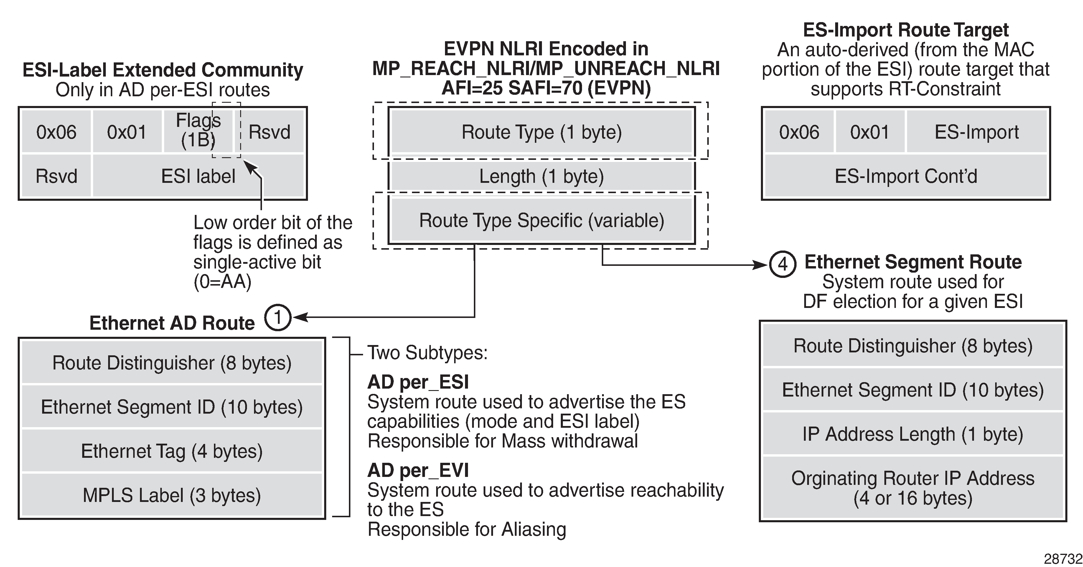
When EVPN multihoming is enabled in the system, two more routes (route types 1 and 4) are required. EVPN Route Type 1 and Type 4 shows the fields in route types 1 and 4 and their associated extended communities.
EVPN Route Type 2 – MAC/IP Advertisement Route
The 7705 SAR generates route type 2 for advertising MAC addresses. If mac-advertisement is enabled, the router generates MAC advertisement routes for the following:
learned MAC addresses on SAPs or SDP bindings
conditional static MAC addresses
Note: The unknown-mac-route command is not supported for EVPN-MPLS services.
Route type 2 uses the fields and values shown in EVPN-MPLS Route Type 2 and Type 3 (Required Routes and Communities) and described in Route Type 2 Fields and Values . For type 2 BGP route key processing, the following fields are considered to be part of the prefix in the NLRI: Ethernet tag ID, MAC address length, MAC address, IP address length, and IP address.
Field |
Value |
|---|---|
Route distinguisher |
Taken from the RD of the VPLS service within the BGP context. The RD can be configured or derived from the bgp-evpn>evi value. |
Ethernet segment identifier (ESI) |
Zero for MAC addresses learned from single-homed CEs and non-zero for MAC addresses learned from multihomed CEs |
Ethernet tag ID |
0 |
MAC address length |
Always 48 |
MAC address |
MAC address learned or statically configured |
IP address and IP address length |
The IP address associated with the MAC address being advertised, with a length of 32 (or 128 for IPv6) In general, any MAC route without an IP address has IPL=0 (IP length) and the IP address is omitted When received, any IPL value not equal to 0, 32, or 128 discards the route |
MPLS label 1 |
Carries the MPLS label allocated by the system to the VPLS service. The label value is encoded in the high-order 20 bits of the field and is the same label used in route type 3 for the same service unless bgp-evpn>mpls>ingress-replication-bum-label is configured in the service. |
MPLS label 2 |
0 |
MAC mobility extended community |
Used for signaling the sequence number in case of MAC moves and the sticky bit in case of advertising conditional static MAC addresses. If a MAC route is received with a MAC mobility extended community, the sequence number and the sticky bit are considered during route selection. |
EVPN Route Type 3 – Inclusive Multicast Ethernet Tag Route
Route type 3 is used for setting up the flooding tree (BMU flooding) for a specified VPLS service. The received inclusive multicast routes add entries to the VPLS flood list in the 7705 SAR. Ingress replication is supported as the tunnel type in route type 3 when BGP-EVPN MPLS is enabled.
EVPN-MPLS Route Type 2 and Type 3 (Required Routes and Communities) shows and Route Type 3 Fields and Values describes the route values used for EVPN-MPLS services. For type 3 BGP route key processing, the following fields are considered to be part of the prefix in the NLRI: Ethernet tag ID, IP address length, and originating router IP address.
Field |
Value |
|
|---|---|---|
Route distinguisher |
Taken from the RD of the VPLS service within the BGP context. The RD can be configured or derived from the bgp-evpn>evi value. |
|
Ethernet tag ID |
0 |
|
IP address length |
Always 32 |
|
Originating router IP address |
Carries the system address (IPv4 only) |
|
PMSI attribute |
The PMSI attribute can have different formats depending on the tunnel type enabled in the service |
|
Tunnel type = ingress replication (6) The route is referred to as an Inclusive Multicast Ethernet Tag IR (IMET-IR) route and the PMSI Tunnel Attribute (PTA) fields are populated as follows: |
||
Flags—Leaf not required MPLS label—Carries the MPLS label allocated for the service in the high-order 20 bits of the label field. Unless bgp-evpn>mpls>ingress-replication-bum-label is configured in the service, the MPLS label used is the same as that used in the MAC/IP routes for the service. Tunnel endpoint—Equal to the originating IP address |
||
EVPN Route Type 1 – Ethernet Auto-Discovery Route (AD Route)
The 7705 SAR generates route type 1 for advertising for multihoming functions. The system can generate the following two subtypes of Ethernet AD routes:
Ethernet AD per-ESI route (Ethernet segment ID)
Ethernet AD per-EVI route (EVPN instance)
The Ethernet AD per-ESI route uses the fields and values shown in EVPN Route Type 1 and Type 4 and described in Route Type 1 Fields and Values (Ethernet AD per-ESI) . For type 1 BGP route key processing, the following fields are considered to be part of the prefix in the NLRI: Ethernet segment identifier and Ethernet tag ID.
Field |
Value |
|---|---|
Route distinguisher |
Taken from the system-level RD or service-level RD |
Ethernet segment identifier (ESI) |
Contains a 10-byte identifier as configured in the system for a specified Ethernet segment |
Ethernet tag ID |
MAX-ET (0xFFFFFFFF). This value is reserved and used only for AD routes per ESI. |
MPLS label |
0 |
ESI label extended community |
Includes the single-active bit (0 for all-active and 1 for single-active) and ESI label for all-active multihoming split-horizon |
Route target extended community |
Taken from the service-level RT or an RT set for the services defined on the Ethernet segment |
The system can send either a separate Ethernet AD per-ESI route per service or several Ethernet AD per-ESI routes aggregating the route targets for multiple services. While both alternatives can interoperate, RFC 7432 states that the EVPN AD per-ES route must be sent with a set of route targets corresponding to all the EVIs defined on the Ethernet segment. Either alternative can be enabled using the ad-per-es-route-target command options.
The default option, evi-rt, configures the system to send a separate AD per-ES route per service.
The evi-rt-set route-distinguisher ip-address option, when enabled, allows the aggregation of routes; that is, a single AD per-ES route with the associated RD (ip-address:1) and a set of EVI route targets are advertised (to a maximum of 128 route targets). If the number of EVIs defined in the Ethernet segment is significantly large for the packet size, the system will send more than one route. For example:
AD per-ES route for EVI-route-set 1 is sent with RD ip-address:1
AD per-ES route for EVI-route-set 2 is sent with RD ip-address:2
The Ethernet AD per-EVI route uses the fields and values shown in EVPN Route Type 1 and Type 4 and described in Route Type 1 Fields and Values (Ethernet AD per-EVI) .
Field |
Value |
|---|---|
Route distinguisher |
Taken from the service-level RD |
Ethernet segment identifier (ESI) |
Contains a 10-byte identifier as configured in the system for a specified Ethernet segment |
Ethernet tag ID |
0 |
MPLS label |
Encodes the unicast label allocated for the service (high-order 20 bits) |
Route target extended community |
Taken from the service-level RT |
EVPN Route Type 4 – Ethernet Segment Route (ES Route)
The 7705 SAR generates route type 4 for multihoming ES discovery and designated forwarder (DF) election.
The Ethernet segment route uses the fields and values shown in EVPN Route Type 1 and Type 4 and described in Route Type 4 Fields and Values . For type 4 BGP route key processing, the following fields are considered to be part of the prefix in the NLRI: Ethernet segment ID, IP address length, and originating router IP address.
Field |
Value |
|---|---|
Route distinguisher |
Taken from the service-level RD |
Ethernet segment identifier (ESI) |
Contains a 10-byte identifier as configured in the system for a specified Ethernet segment |
ES-import route target community |
Automatically derived value from the MAC address portion of the ESI. This extended community is treated as a route target and is supported by RT-constraint (route target BGP family). |
EVPN Route Type 5 – IP Prefix Route
EVPN route type 5 (IP prefix route) is supported for MPLS tunnels. The route fields for route type 5 are shown in EVPN Route Type 5 and described in Route Type 5 Fields and Values . For type 5 BGP route key processing, the following fields are considered to be part of the prefix in the NLRI: Ethernet tag ID, IP prefix length, and IP prefix.
All the routes in EVPN-MPLS are sent with the RFC 5512 tunnel encapsulation extended community, with the tunnel type value set to MPLS.
The router generates route type 5 for advertising IP prefixes in EVPN. The router generates IP prefix advertisement routes for:
IP prefixes existing in a VPRN linked to the integrated routing and bridging (IRB) backhaul r-VPLS service
The IRB interface refers to an r-VPLS service bound to a VPRN IP interface.
Field |
Value |
|---|---|
Route distinguisher |
Taken from the RD configured in the IRB backhaul r-VPLS service within the BGP context |
Ethernet segment identifier (ESI) |
0:0:0:0:0:0:0:0:0:0 |
Ethernet tag ID |
0 |
IP address length |
Any value in the range 0 to 128 |
IP address |
Any valid IPv4 or IPv6 address |
GW IP address |
Can carry two different values: - If different from 0, route type 5 carries the primary IP interface address of the VPRN behind which the IP prefix is known. This is the case for the regular IRB backhaul r-VPLS model. - If 0.0.0.0, the route type 5 is sent with a MAC next-hop extended community that carries the VPRN interface MAC address. This is the case for the EVPN tunnel r-VPLS model. |
MPLS label |
Carries the MPLS label allocated for the service Only one MPLS label can be configured per VPLS service |
RFC 5512 – BGP Tunnel Encapsulation Extended Community
The following routes are sent with the RFC 5512 BGP tunnel encapsulation extended community: route type 2 (MAC/IP), route type 3 (Inclusive Multicast Ethernet Tag), and route type 1 (Ethernet AD per-EVI). Route type 4 (Ethernet segment) and route type 1 (AD per-ESI) routes are not sent with this extended community.
The router processes the following BGP tunnel-encapsulation tunnel values registered by IANA for RFC 5512:
MPLS encapsulation: 10
Any other tunnel value gives the route ‟treat-as-withdraw” status.
If the encapsulation value is MPLS, the BGP validates the high-order 20 bits of the label field, ignoring the low-order 4 bits.
If the encapsulation extended community is not present in a received route, BGP treats the route as an MPLS-based configuration of the config>router>bgp>group>neighbor>def-recv-evpn-encap mpls command. The command is also available at the bgp and group levels.
EVPN-VPLS for MPLS Tunnels
This section provides information on the following topics:
Overview
EVPN can be used in MPLS networks where PEs are interconnected through any type of tunnel, including RSVP-TE, segment routing TE, LDP, BGP, segment routing IS-IS, and segment routing OSPF. The selection of the tunnel to be used in a VPLS service with BGP-EVPN MPLS enabled is based on the auto-bind-tunnel command, which is similar to the way that VPRN services operate.
EVPN-MPLS is modeled using a VPLS service where EVPN-MPLS bindings can coexist with SAPs and SDP bindings. The following output shows an example of a VPLS service with EVPN-MPLS.
*A:PE-1>config>service>vpls# info
----------------------------------------------
  description "evpn-mpls-service"
  bgp
  bgp-evpn
    evi 10
    mpls
      no shutdown
      auto-bind-tunnel resolution any
  sap 1/1/1:1 create
  exit
  spoke-sdp 1:1 create
The bgp-evpn context must be enabled when MPLS is not shutdown. In addition to the mpls>no shutdown command, the minimum set of commands needed to set up the EVPN-MPLS instance are the bgp-evpn>evi and the bgp-evpn>mpls>auto-bind-tunnel resolution commands. Users can also configure other command options. The minimum set and optional commands are listed below:
evi value — the EVPN identifier value (EVI value) is unique in the system and can have a value between 1 and 65535. The EVI value is used for the service-carving algorithm (which is used for multihoming, if configured) and for auto-deriving route target and route distinguishers in the service.
If the evi value is not specified, its value is 0 and no route distinguisher or route targets are auto-derived from it. If the evi value is specified and no other route distinguisher or route targets are configured in the service, the following derivations apply:
the route distinguisher is derived from system-ip:evi value
the route target is derived from autonomous-system:evi value
Note: When the vsi-import and vsi-export policies are configured, the route target must be configured in the policies and the policy values take preference over the values of auto-derived route targets. The operational route target for a service is displayed using the show service id service-id bgp command.When the evi command is configured, a config>service>vpls>bgp command is required—even if the context is empty—to allow the user to see the correct information when using the show>service>id service-id>bgp and show>service>system>bgp-route-distinguisher commands.
Although it is not mandatory, if multihoming is not configured, the configuration of the evi command is enforced for EVPN services with SAPs or SDP bindings defined in the ethernet-segment command. See EVPN Multihoming in VPLS Services for more information about the ethernet-segment command.
The following options are specific to EVPN-MPLS and defined in the bgp-evpn>mpls context:
control-word — this command is required, as per RFC 7432, to avoid frame disordering. The user can enable and disable it so that interoperability with other vendors can be guaranteed.
auto-bind-tunnel — this command is required and allows the user to decide what type of MPLS transport tunnels are used for a particular instance. The command is used in the same way as it is used in VPRN services.
For BGP-EVPN MPLS, bgp is explicitly added to the resolution-filter in EVPN (bgp is implicit in VPRNs).
force-vlan-vc-forwarding — this command allows the system to preserve the VLAN ID and P-bits of the service-delimiting qtag in a new tag added in the customer frame before sending the customer frame to the EVPN core.
split-horizon-group — this command allows the association of a user-created split horizon group with all the EVPN-MPLS destinations. See EVPN and VPLS Integration for more information.
ecmp — this command, when set to a value greater than 1, activates aliasing to the remote PEs that are defined in the same all-active multihoming Ethernet segment. See EVPN Multihoming in VPLS Services for more information.
ingress-replication-bum-label — this command is only enabled when the user wants the PE to advertise a label for BMU traffic (Inclusive Multicast Ethernet Tag routes, route type 3) that is different from the label advertised for unicast traffic (with the MAC/IP routes). This is useful to avoid potential transient packet duplication in all-active multihoming.
In addition to the options above, the following bgp-evpn commands are also available for EVPN-MPLS services:
[no] mac-advertisement
mac-duplication and settings
When EVPN-MPLS is established among some PEs in the network, EVPN unicast and multicast bindings are created on each PE to the remote EVPN destinations. A specified ingress PE creates:
a unicast EVPN-MPLS destination binding to a remote egress PE as soon as a MAC/IP route is received from that egress PE
a multicast EVPN-MPLS destination binding to a remote egress PE, only if the egress PE advertises an Inclusive Multicast Ethernet Tag route (route type 3) with a BMU label. This is only possible if the egress PE is configured with ingress-replication-bum-label.
The unicast and multicast bindings, as well as the MAC addresses learned on them, can be checked using the show commands in the following example. In the example, the remote PE 192.0.2.69 is configured with no ingress-replication-bum-label and PE 192.0.2.70 is configured with ingress-replication-bum-label. Therefore, ‟Dut” has a single EVPN-MPLS destination binding to PE 192.0.2.69 and two bindings (unicast and multicast) to PE 192.0.2.70.
*A:Dut# show service id 1 evpn-mpls

===============================================================================
BGP EVPN-MPLS Dest
===============================================================================
TEP Address     Egr Label     Num. MACs   Mcast           Last Change
                 Transport
-------------------------------------------------------------------------------
192.0.2.69      262118        1           Yes             06/11/2015 19:59:03
                ldp
192.0.2.70      262139        0           Yes             06/11/2015 19:59:03
                ldp
192.0.2.70      262140        1           No              06/11/2015 19:59:03
                ldp
192.0.2.72      262140        0           Yes             06/11/2015 19:59:03
                ldp
192.0.2.72      262141        1           No              06/11/2015 19:59:03
                ldp
192.0.2.73      262139        0           Yes             06/11/2015 19:59:03
                ldp
192.0.2.254     262142        0           Yes             06/11/2015 19:59:03
                bgp
-------------------------------------------------------------------------------
Number of entries : 7
-------------------------------------------------------------------------------
===============================================================================
*A:Dut# show service id 1 fdb detail

===============================================================================
Forwarding Database, Service 1
===============================================================================
ServId    MAC               Source-Identifier        Type     Last Change
                                                     Age
-------------------------------------------------------------------------------
1         00:ca:fe:ca:fe:69 eMpls:                   EvpnS    06/11/15 21:53:48
                            192.0.2.69:262118
1         00:ca:fe:ca:fe:70 eMpls:                   EvpnS    06/11/15 19:59:57
                            192.0.2.70:262140
1         00:ca:fe:ca:fe:72 eMpls:                   EvpnS    06/11/15 19:59:57
                            192.0.2.72:262141
-------------------------------------------------------------------------------
No. of MAC Entries: 3
-------------------------------------------------------------------------------
Legend:  L=Learned O=Oam P=Protected-MAC C=Conditional S=Static
===============================================================================
EVPN and VPLS Integration
The 7705 SAR EVPN implementation supports draft-ietf-bess-evpn-vpls-seamless-integ so that EVPN-MPLS and VPLS can be integrated into the same network and within the same service. This feature is useful for the integration between both technologies and for the migration of VPLS services to EVPN-MPLS.
The following behavior enables the integration of EVPN and SDP bindings in the same VPLS network. An illustration and configuration example follow the list.
Systems with EVPN endpoints and SDP bindings to the same far end bring down the SDP bindings.
The router allows the establishment of an EVPN endpoint and an SDP binding to the same far end but the SDP binding is kept operationally down. Only the EVPN endpoint is operationally up. This is true for spoke SDPs and mesh SDPs.
If there is an existing EVPN endpoint to a specified far end and the establishment of a spoke SDP is attempted, the spoke SDP is set up but kept operationally down with an operational flag indicating that there is an EVPN route to the same far end.
If there is an existing spoke SDP and a valid (used) EVPN route arrives, the EVPN endpoint is set up and the spoke SDP is brought operationally down with an operational flag indicating that there is an EVPN route to the same far end.
If there is an SDP binding and EVPN endpoint to different far-end IP addresses on the same remote PE, both links will be operationally up. This can happen if the SDP binding is terminated in an IPv6 address or IPv4 address that is different from the system address where the EVPN endpoint is terminated.
The user can add spoke SDPs and all the EVPN-MPLS endpoints in the same split horizon group.
The split-horizon-group group-name command under the vpls>bgp-evpn>mpls context allows the EVPN-MPLS endpoints to be added to a split horizon group.
The bgp-evpn>mpls>split-horizon-group must reference a user-configured split horizon group. User-configured split horizon groups can be configured within the service>vpls context. The same group-name can be associated with SAPs, spoke SDPs, and EVPN-MPLS endpoints.
If the split-horizon-group command is not used, the default split horizon group—which contains all the EVPN endpoints—is still used, but it is not possible to refer to it on SAPs and spoke SDPs.
The system disables the advertisement of MAC addresses learned on SAPs and spoke SDPs that are part of an EVPN split horizon group.
When the SAPs and spoke SDPs are configured within the same split horizon group as the EVPN endpoints, MAC addresses are still learned on them but are not advertised in EVPN.
The SAPs and spoke SDPs added to an EVPN split horizon group should not be part of any EVPN multihomed ES. In this case, the PE still advertises the AD per-EVI route for the SAP or spoke SDP, attracting EVPN traffic that could not be forwarded to that SAP or SDP binding.
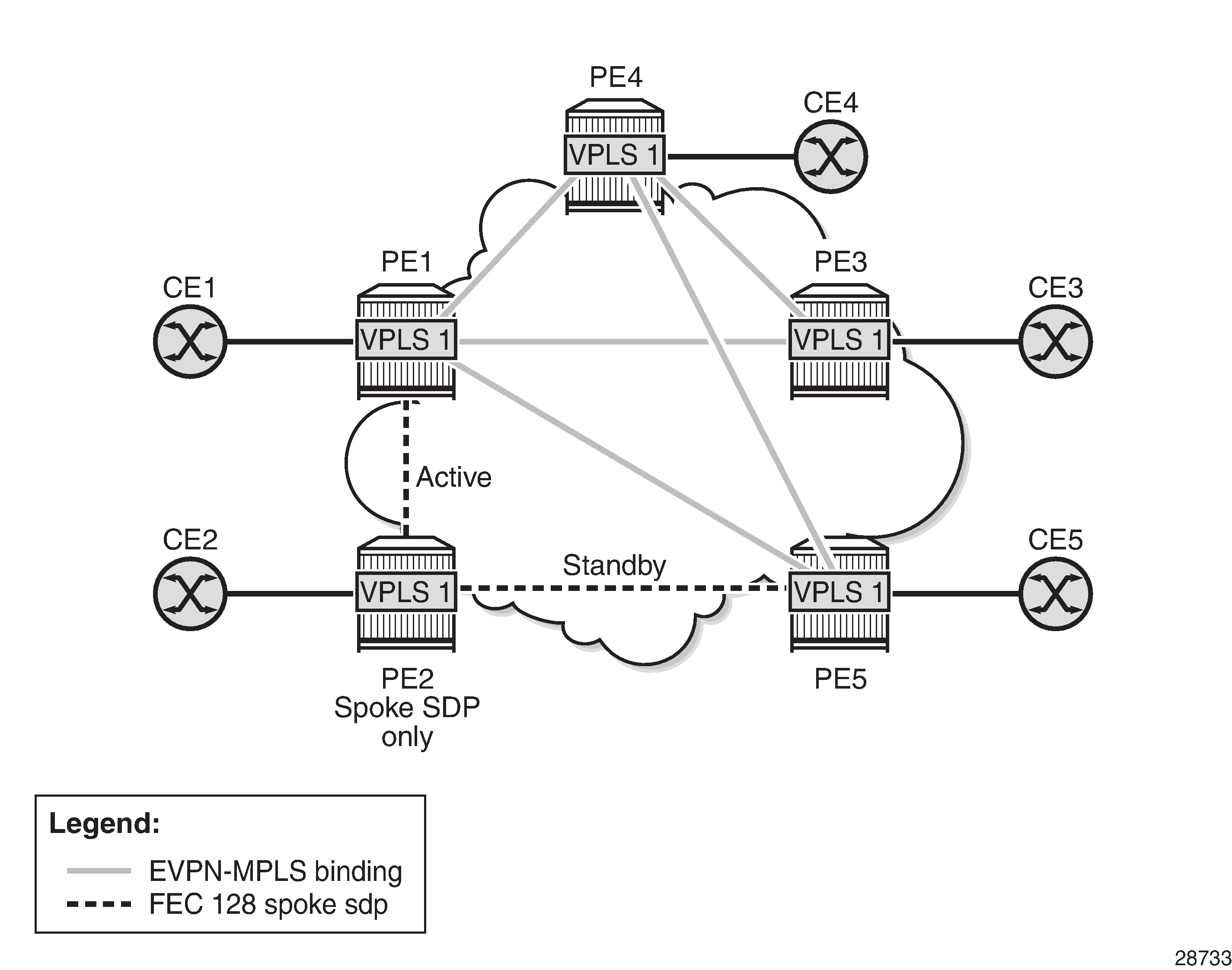
EVPN-VPLS Integration shows an example of EVPN-VPLS integration. In this example, if EVPN and SAPs and spoke SDPs are part of the same split horizon group, the traffic arriving on the SAPs and spoke SDPs is not forwarded to EVPN.
The spoke SDPs on PE2 are not part of an split horizon group, so they can forward traffic to EVPN. Spoke SDPs on PE5 are part of same split horizon group, so they cannot forward traffic to EVPN.
A CLI configuration example for PE1, PE5, and PE2 is provided below.
*A:PE1>config>service# info
----------------------------------------------
vpls 1 customer 1 create
  split-horizon-group "SHG-1" create
  bgp
    route-target target:65000:1
  bgp-evpn
    evi 1
    mpls
      no shutdown
      split-horizon-group SHG-1
  spoke-sdp 12:1 create
  exit
  sap 1/1/1:1 create
  exit
PE5#config>service# info
----------------------------------------------
vpls 1 customer 1 create
    split-horizon-group "SHG-1" create
    exit
    stp
        shutdown
    exit
    endpoint "vpls20" create
    exit
    sap 1/1/7:2 create
        no shutdown
    exit
    spoke-sdp 64:2 split-horizon-group "SHG-1" endpoint "vpls20" create
        no shutdown
    exit
    spoke-sdp 65:2 split-horizon-group "SHG-1" endpoint "vpls20" create
        no shutdown
    exit
    no shutdown
*A:PE2>config>service# info
----------------------------------------------
vpls 1 customer 1 create
  end-point CORE create
    no suppress-standby-signaling
  spoke-sdp 21:1 end-point CORE
    precedence primary
  spoke-sdp 25:1 end-point CORE
PE1, PE3, PE4, and PE5 have BGP-EVPN enabled in VPLS-1. PE2 has active/standby spoke SDPs to PE1 and PE5. In this configuration:
EVPN endpoints are instantiated within the same split horizon group, for example, SHG-1
manual spoke SDPs from PE1 and PE5 to PE2 are not part of SHG-1
EVPN MAC advertisements are as follows.
MAC addresses learned on FEC128 spoke SDPs are advertised normally in EVPN.
MAC addresses learned on spoke SDPs that are part of SHG-1 are not advertised in EVPN because SHG-1 is the split horizon group used for bgp-evpn>mpls. This prevents any data plane MAC addresses learned on the split horizon group from being advertised in EVPN.
BMU operation on PE1 is as follows.
When CE1 sends BMU traffic, PE1 floods it to all the active bindings.
When CE2 sends BMU traffic, PE2 sends it to PE1 (active spoke SDP) and PE1 floods it to all the bindings and SAPs.
When CE5 sends BMU traffic, PE5 floods it to the EVPN PEs. PE1 will flood the traffic to the active spoke SDP and SAPs but never to the EVPN PEs because they are part of the same split horizon group.
Auto-derived Route Distinguisher (RD) in Services
In a VPLS service, a single RD is used per service.
The following rules apply.
-
The VPLS RD is selected based on the following precedence:
-
a manual RD always take precedence when configured
-
if there is no manual configuration, the RD is derived from the bgp-evpn>evi configuration
-
if there is no manual or evi configuration, there will not be an RD and the service will fail
-
-
The selected RD is displayed in the ‟Oper Route Dist” field of the show>service>id>bgp command.
-
The service supports dynamic RD changes, such as a new manual RD configuration.
Note: When the RD changes, the active routes for that VPLS are withdrawn and readvertised with the new RD. -
If the manual mechanism to derive the RD for a specified service is removed from the configuration, the system will select a new RD based on the above rules. In this case, the routes are withdrawn, the new RD is selected from the evi configuration, and the routes are readvertised with the new RD.
Note: This reconfiguration will fail if the new RD already exists in a different VPLS or Epipe service.
EVPN Multihoming in VPLS Services
EVPN multihoming implementation is based on the concept of the Ethernet segment and configured through the ethernet-segment command. An Ethernet segment is a logical structure that can be defined in one or more PEs and identifies the CE (or access network) that is multihomed to the EVPN PEs. An Ethernet segment is associated with port, LAG, or SDP objects and is shared by all the services defined on those objects. For virtual Ethernet segments, individual VID or VC-ID ranges can be associated with the port, LAG, or SDP objects defined in the Ethernet segment.
Each Ethernet segment has a unique identifier called the Ethernet segment identifier (ESI) that is 10 bytes long and is manually configured in the router.
This section describes the behavior of the EVPN multihoming implementation in an EVPN-MPLS service and includes the following topics:
EVPN All-Active Multihoming
This section contains information on the following topics:
all-active multihoming service mode
ES discovery and DF election procedures (all-active multihoming)
aliasing
network failures and convergence for all-active multihoming
As described in RFC 7432, all-active multihoming is only supported on access LAG SAPs. The CE must be configured with a LAG to avoid duplicated packets to the network. The use of LACP is optional.
Three different procedures are implemented in the 7705 SAR to provide all-active multihoming for a specified Ethernet segment:
designated forwarder (DF) election (see DF Election)
split horizon (see Split Horizon)
aliasing (see Aliasing)
DF Election shows the need for DF election in all-active multihoming.
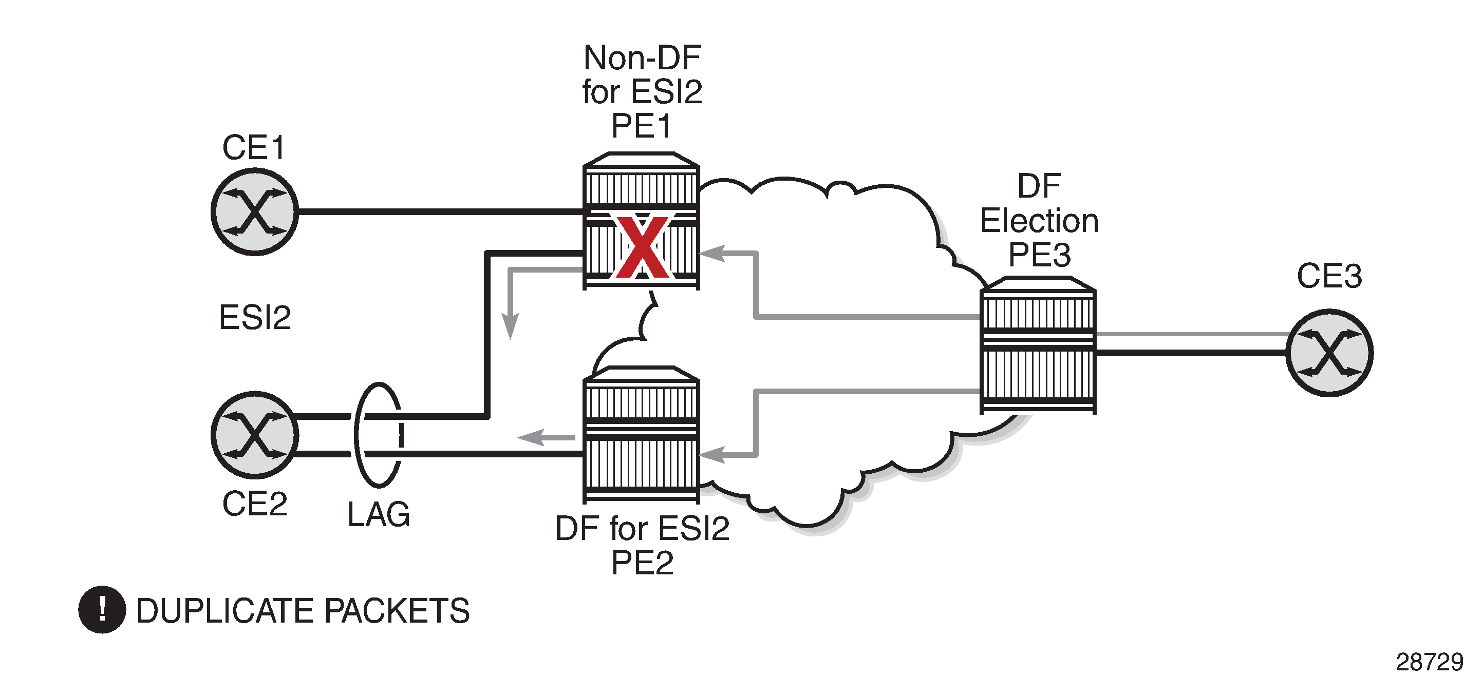
The DF election in an EVPN all-active multihoming scenario avoids duplicate packets on the multihomed CE. The DF election procedure is responsible for electing one DF PE per ESI per service; the other PEs are non-DF for the ESI and service. Only the DF forwards BMU traffic from the EVPN network toward the ES SAPs (the multihomed CE). The non-DF PEs do not forward BMU traffic to the local Ethernet segment SAPs (see ES Discovery and DF Election Procedures (all-active multihoming) for more information).
Split Horizon shows the EVPN split-horizon concept for all-active multihoming.
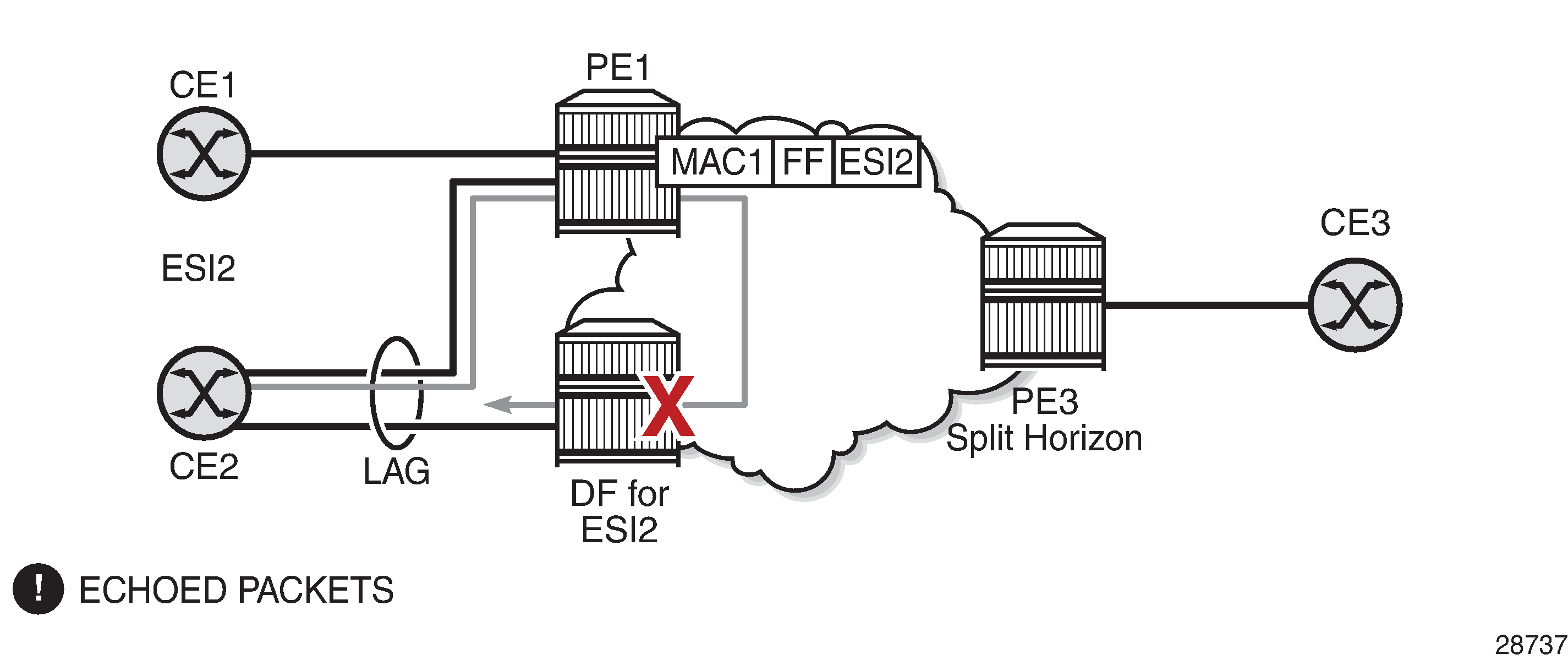
The EVPN split-horizon procedure ensures that the BMU traffic originated by the multihomed PE and sent from the non-DF to the DF is not replicated back to the CE (echoed packets on the CE). To avoid these echoed packets, the non-DF (PE1) sends all the BMU packets to the DF (PE2) with an indication of the source Ethernet segment. That indication is the ESI label (ESI2 in the example), previously signaled by PE2 in the AD per-ESI route for the Ethernet segment. When PE2 receives an EVPN packet (after the EVPN label lookup), PE2 finds the ESI label that identifies its local Ethernet segment (ESI2). The BMU packet is replicated to other local CEs but not to the ESI2 SAP.
Aliasing shows the EVPN aliasing concept for all-active multihoming.
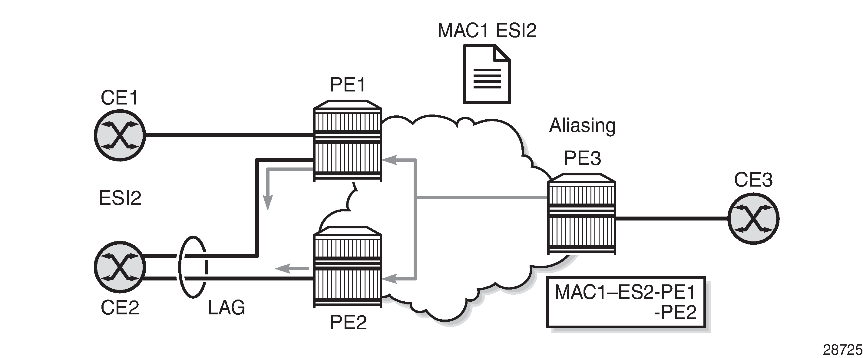
Because CE2 is multihomed to PE1 and PE2 using an all-active Ethernet segment, aliasing is the procedure by which PE3 can load-balance the known unicast traffic between PE1 and PE2, even if the destination MAC address was only advertised by PE1, as shown in the example. When PE3 installs MAC1 in the FDB, it associates MAC1 not only with the advertising PE (PE1) but also with all the PEs advertising the same esi esi (ESI2) for the service. In this example, PE1 and PE2 advertise an AD per-EVI route for ESI2. Therefore, PE3 installs the two next hops associated with MAC1.
Aliasing is enabled by configuring ECMP to be greater than 1 in the bgp-evpn>mpls context (see Aliasing for more information).
All-Active Multihoming Service Model
The following shows an example where the PE1 configuration provides all-active multihoming to the CE2 shown in Aliasing.
*A:PE1>config>lag(1)# info
----------------------------------------------
  mode access
  encap-type dot1q
  port 1/1/2
  lacp active administrative-key 1 system-id 00:00:00:00:00:22
  no shutdown

*A:PE1>config>service>system>bgp-evpn# info
----------------------------------------------
  route-distinguisher 1.1.1.1:0
  ethernet-segment "ESI2" create
    esi 01:12:12:12:12:12:12:12:12:12
    multi-homing all-active
    service-carving
    lag 1
    no shutdown

*A:PE1>config>redundancy>evpn-multi-homing# info
----------------------------------------------
    boot-timer 120
    es-activation-timer 10

*A:PE1>config>service>vpls# info
----------------------------------------------
  description "evpn-mpls-service with all-active multihoming"
  bgp
  bgp-evpn
    evi 10
    mpls
      no shutdown
      auto-bind-tunnel resolution any
  sap lag-1:1 create
  exit
In the same way, PE2 is configured as follows:
*A:PE2>config>lag(1)# info
----------------------------------------------
  mode access
  encap-type dot1q
  port 1/1/1
  lacp active administrative-key 1 system-id 00:00:00:00:00:22
  no shutdown

*A:PE2>config>service>system>bgp-evpn# info
----------------------------------------------
  route-distinguisher 1.1.1.1:0
  ethernet-segment "ESI12" create
    esi 01:12:12:12:12:12:12:12:12:12
    multi-homing all-active
    service-carving
    lag 1
    no shutdown

*A:PE2>config>redundancy>evpn-multi-homing# info
----------------------------------------------
    boot-timer 120
    es-activation-timer 10

*A:PE2>config>service>vpls# info
----------------------------------------------
  description "evpn-mpls-service with all-active multihoming"
  bgp
    route-distinguisher 65001:60
    route-target target:65000:60
  bgp-evpn
    evi 10
    mpls
      no shutdown
      auto-bind-tunnel resolution any
  sap lag-1:1 create
  exit
The preceding configuration enables the all-active multihoming procedures. The following must be considered.
The Ethernet segment must be configured with a name and a 10-byte esi esi value:
config>service>system>bgp-evpn>ethernet-segment name create
config>service>system>bgp-evpn>ethernet-segment>esi esi
When configuring the esi value, the system enforces the rule that the six high-order octets after the type field are not 0 (so that the auto-derived route target for the ES route is different from 0). Otherwise, the entire esi value must be unique in the system.
Only a LAG can be associated with the Ethernet segment. The LAG is used exclusively for EVPN multihoming. Other LAG ports in the system can still be used for MC-LAG and other services.
When the LAG is configured on PE1 and PE2, the same admin-key, system-priority, and system-id must be configured on both PEs so that CE2 responds as though it is connected to the same system.
Only one SAP per service can be part of the same Ethernet segment.
ES Discovery and DF Election Procedures (all-active multihoming)
The Ethernet segment (ES) discovery and DF election is implemented in three steps (described below and illustrated in ES Discovery and DF Election).
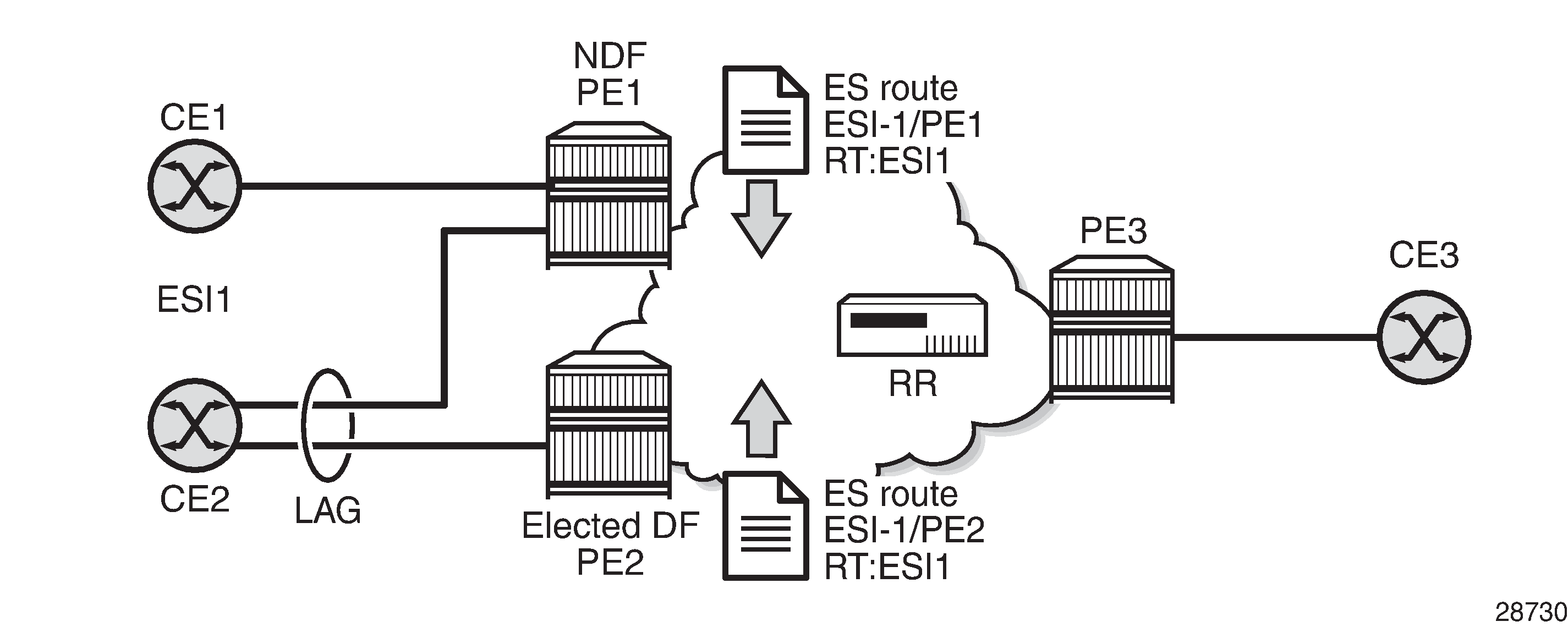
Step 1 – ES Advertisement and Discovery
Ethernet segment ESI-1 is configured as described in the previous section (All-Active Multihoming Service Model), with all the required parameters. When ethernet-segment>no shutdown is executed, PE1 and PE2 advertise an ES route for ESI-1. Both PEs include the route target auto-derived from the MAC address portion of the configured ESI. If the route target address family is configured in the network, it allows the RR to keep the dissemination of the ES routes under control.
In addition to the ES route, PE1 and PE2 advertise AD per-ESI routes and AD per-EVI routes.
AD per-ESI routes announce the Ethernet segment capabilities, including the mode (single-active or all-active) and the ESI label for split horizon.
AD per-EVI routes are advertised so that PE3 knows which services (EVIs) are associated with the ESI. These routes are used by PE3 for its aliasing and backup procedures.
Step 2 – DF Election
When the exchange of ES routes between PE1 and PE2 is complete, both PEs run the DF election for all the services in the Ethernet segment.
PE1 and PE2 elect a DF for an ESI-service pair (that is, per ESI, per service). The default DF election mechanism in the 7705 SAR is service-carving mode auto, as per RFC 7432. It is possible to manually control the method of selecting a DF by using a preference-based algorithm as described in draft-rabadan-bess-evpn-pref-df through the service-carving manual CLI context; see Preference-Based and Non-Revertive Designated Forwarder Election for information.
The following items apply when the default service carving mode is used on a specified PE. The DF election does not occur until the Ethernet segment is configured as no shutdown.
An ordered list of PE IP addresses where ESI-1 resides is built. The IP addresses are obtained from the ‟Origin IP” fields of all the ES routes received for ESI-1 and also include the local system address. The lowest IP address is considered ordinal ‟0” in the list.
The local IP address can only be considered a candidate after a successful ethernet-segment>no shutdown command for a specified service.
Note: The remote PE IP addresses must be present in the local PE RTM so that they can participate in the DF election.A PE only considers a specified remote IP address as a candidate for the DF election algorithm for a specified service if, in addition to the ES route, the corresponding AD per-ESI and per-EVI routes for that PE have been received and properly activated.
All remote PEs receiving the AD per-ES routes (for example, PE3) interpret ESI-1 as all-active if all the PEs send their AD per-ES routes with the single-active bit = 0. Otherwise, if at least one PE sends an AD per-ESI route with the single-active flag set or if the local ESI configuration is single-active, the ESI behavior is single-active.
An es-activation-timer can be configured at the redundancy>bgp-evpn-multi-homing>es-activation-timer level or at the service>system>bgp-evpn>ethernet-segment>es-activation-timer level. This timer, which is 3 seconds by default, delays the transition from non-DF to DF for a specified service after the DF election has run.
This use of the es-activation-timer with a value different from 0 minimizes the risk of loops and packet duplication due to multiple DFs in transient states.
The same es-activation-timer value should be configured for all the PEs that are part of the same ESI. The user can configure a long timer to minimize the risk of loops or duplication or a short timer (even es-activation-timer = 0) to speed up the convergence for non-DF to DF transitions. When the user configures a specific value, the value configured at the Ethernet segment level supersedes the configured global value.
The DF election is triggered by the following events.
The config>service>system>bgp-evpn>eth-seg>no shutdown command triggers the DF election for all the services in the ESI.
Reception of a new update or withdrawal of an ES route (containing an ESI configured locally) triggers the DF election for all the services in the ESI.
Reception of a new update or withdrawal of an AD per-ES route (containing an ESI configured locally) triggers the DF election for all the services associated with the list of route targets received along with the route.
Reception of a new update of an AD per-ES route with a change in the ESI-label extended community (single-active bit or MPLS label) triggers the DF election for all the services associated with the list of route targets received along with the route.
Reception of a new update or withdrawal of an AD per-EVI route (containing an ESI configured locally) triggers the DF election for that service.
When the PE boots up, the boot timer allows the necessary time for the control plane protocols to come up before bringing up the Ethernet segment and running the DF algorithm. The boot timer is configured at the system level (config>redundancy>bgp-evpn-multi-homing>boot-timer) and should have a value long enough to allow the IOMs and BGP sessions to come up before exchanging ES routes and running the DF election for each EVI.
The system does not advertise ES routes until the boot timer expires. This guarantees that the peer ES PEs do not run the DF election until the PE is ready to become the DF, if necessary.
The following show command displays the configured boot timer value as well as the remaining timer value if the system is still in boot stage.
         A:PE1# show redundancy bgp-evpn-multi-homing
         ========================================================================
         Redundancy BGP EVPN Multi-homing Information
         ========================================================================
         Boot-Timer              : 10 secs
         Boot-Timer Remaining    : 0 secs
         ES Activation Timer     : 3 secs
         ========================================================================
When the service-carving mode auto command is configured (auto is the default mode), the DF election algorithm runs the following function to identify the DF for a specified service and ESI:
V mod N = i (ordinal)
where V is the EVI and N is the number of peers, for example:
as shown in ES Discovery and DF Election, PE1 and PE2 are configured with ESI-1. If V = 10 and N = 2, then V mod N = 0, and PE1 would be elected DF—its IP address is lower than PE2's IP address and it is the first PE in the candidate list.
Note: The algorithm uses the configured evi value in the service rather than the service-id. The evi value for a service must match for all the PEs that are part of the ESI. This guarantees that the election algorithm is consistent across all the PEs of the ESI. The evi value must always be configured in a service with SAPs or SDP bindings that are created in an ES.
The user can manually configure the evi identifiers for which the PE is primary, using the commands:
service-carving>mode manual and
service-carving>manual evi start [to to]
The system will be the primary PE, forwarding or multicasting traffic for the evi identifiers included in the configuration. The PE will be secondary (non-DF) for the non-specified EVIs.
If a range is configured but the service-carving mode is not manual, the range has no effect.
Only two PEs are supported when service-carving mode manual is configured. If a third PE is configured with service-carving mode manual for an ESI, the two non-primary PEs remain non-DF regardless of the primary status.
For example, as shown in ES Discovery and DF Election, if PE1 is configured with service-carving manual evi 1 to 100 and PE2 with service-carving manual evi 101 to 200, then PE1 will be the primary PE and PE2 will be the secondary PE.
When service-carving is disabled, the lowest originator IP address will win the election for a specified service and ESI. The following command disables service carving:
config>service>system>bgp-evpn>ethernet-segment>service-carving mode off
The following show command displays the Ethernet segment configuration and DF status for all EVIs configured in the Ethernet segment.
*A:PE1# show service system bgp-evpn ethernet-segment name "ESI-1" all
===============================================================================
Service Ethernet Segment
===============================================================================
Name                    : ESI-1
Admin State             : Up                 Oper State         : Up
ESI                     : 01:00:00:00:00:71:00:00:00:01
Multi-homing            : allActive          Oper Multi-homing  : allActive
Source BMAC LSB         : 71-71
ES BMac Tbl Size        : 8                  ES BMac Entries    : 1
Lag Id                  : 1
ES Activation Timer     : 0 secs
Exp/Imp Route-Target    : target:00:00:00:00:71:00

Svc Carving             : auto
ES SHG Label            : 262142
===============================================================================
===============================================================================
EVI Information
===============================================================================
EVI                 SvcId               Actv Timer Rem      DF
-------------------------------------------------------------------------------
1                   1                   0                   no
-------------------------------------------------------------------------------
Number of entries: 1
===============================================================================
-------------------------------------------------------------------------------
DF Candidate list
-------------------------------------------------------------------------------
EVI                                     DF Address
-------------------------------------------------------------------------------
1                                       192.0.2.69
1                                       192.0.2.72
-------------------------------------------------------------------------------
Number of entries: 2
-------------------------------------------------------------------------------
-------------------------------------------------------------------------------
===============================================================================
ISID Information
===============================================================================
ISID                SvcId               Actv Timer Rem      DF
-------------------------------------------------------------------------------
20001               20001               0                   no
-------------------------------------------------------------------------------
Number of entries: 1
===============================================================================

-------------------------------------------------------------------------------
DF Candidate list
-------------------------------------------------------------------------------
ISID                                    DF Address
-------------------------------------------------------------------------------
20001                                   192.0.2.69
20001                                   192.0.2.72
-------------------------------------------------------------------------------
Number of entries: 2
-------------------------------------------------------------------------------
-------------------------------------------------------------------------------
===============================================================================
BMAC Information
===============================================================================
SvcId                                   BMacAddress
-------------------------------------------------------------------------------
20000                                   00:00:00:00:71:71
-------------------------------------------------------------------------------
Number of entries: 1
===============================================================================
Step 3 – DF and Non-DF Service Behavior
Based on the result of the DF election or the manual service carving, the control plane on the non-DF (PE1) instructs the data path to remove the LAG SAP associated with the ESI from the default flooding list for broadcast and multicast (BM) traffic. Unknown unicast traffic may still be sent if the EVI label is a unicast label and the source MAC address is not associated with the ESI.
On PE1 and PE2, both LAG SAPs learn the same MAC address (coming from the CE). For example, in the following show commands, 00:ca:ca:ba:ce:03 is learned on both the PE1 and PE2 access LAG (on ESI-1). However, PE1 learns the MAC address as ‟Learned” whereas PE2 learns it as ‟Evpn”. This is due to CE2 switching the traffic for that source MAC address to PE1. PE2 learns the MAC address through EVPN but it associates the MAC address with the ESI SAP because the MAC address belongs to the ESI.
*A:PE1# show service id 1 fdb detail
===============================================================================
Forwarding Database, Service 1
===============================================================================
ServId    MAC               Source-Identifier        Type     Last Change
                                                     Age
-------------------------------------------------------------------------------
1         00:ca:ca:ba:ce:03 sap:lag-1:1              L/0      06/11/15 00:14:47
1         00:ca:fe:ca:fe:70 eMpls:                   EvpnS    06/11/15 00:09:06
                            192.0.2.70:262140
1         00:ca:fe:ca:fe:72 eMpls:                   EvpnS    06/11/15 00:09:39
                            192.0.2.72:262141
-------------------------------------------------------------------------------
No. of MAC Entries: 3
-------------------------------------------------------------------------------
Legend:  L=Learned O=Oam P=Protected-MAC C=Conditional S=Static
===============================================================================

*A:PE2# show service id 1 fdb detail
===============================================================================
Forwarding Database, Service 1
===============================================================================
ServId    MAC               Source-Identifier        Type     Last Change
                                                     Age
-------------------------------------------------------------------------------
1         00:ca:ca:ba:ce:03 sap:lag-1:1              Evpn     06/11/15 00:14:47
1         00:ca:fe:ca:fe:69 eMpls:                   EvpnS    06/11/15 00:09:40
                            192.0.2.69:262141
1         00:ca:fe:ca:fe:70 eMpls:                   EvpnS    06/11/15 00:09:40
                            192.0.2.70:262140
-------------------------------------------------------------------------------
No. of MAC Entries: 3
-------------------------------------------------------------------------------
Legend:  L=Learned O=Oam P=Protected-MAC C=Conditional S=Static
===============================================================================
When PE1 (non-DF) and PE2 (DF) exchange BMU packets for evi 1, all the packets are sent with the ESI label included at the bottom of the stack (in both directions). The ESI label advertised by PE1 and PE2 for ESI-1 can be displayed using the following commands:
*A:PE1# show service system bgp-evpn ethernet-segment name "ESI-1"
===============================================================================
Service Ethernet Segment
===============================================================================
Name                    : ESI-1
Admin State             : Up                 Oper State         : Up
ESI                     : 01:00:00:00:00:71:00:00:00:01
Multi-homing            : allActive          Oper Multi-homing  : allActive
Source BMAC LSB         : 71-71
ES BMac Tbl Size        : 8                  ES BMac Entries    : 1
Lag Id                  : 1
ES Activation Timer     : 0 secs
Exp/Imp Route-Target    : target:00:00:00:00:71:00

Svc Carving             : auto
ES SHG Label            : 262142
===============================================================================

*A:PE2# show service system bgp-evpn ethernet-segment name "ESI-1"

===============================================================================
Service Ethernet Segment
===============================================================================
Name                    : ESI-1
Admin State             : Up                 Oper State         : Up
ESI                     : 01:00:00:00:00:71:00:00:00:01
Multi-homing            : allActive          Oper Multi-homing  : allActive
Source BMAC LSB         : 71-71
ES BMac Tbl Size        : 8                  ES BMac Entries    : 0
Lag Id                  : 1
ES Activation Timer     : 20 secs
Exp/Imp Route-Target    : target:00:00:00:00:71:00

Svc Carving             : auto
ES SHG Label            : 262142
===============================================================================
Aliasing
Following the example in ES Discovery and DF Election, if the service configuration on PE3 has ECMP > 1, then PE3 adds PE1 and PE2 to the list of next hops for ESI-1. As soon as PE3 receives a MAC address for ESI-1, it starts load-balancing the flows, per service, between PE1 and PE2 to the remote ESI CE. The following command shows the FDB in PE3.
*A:PE3# show service id 1 fdb detail
===============================================================================
Forwarding Database, Service 1
===============================================================================
ServId    MAC               Source-Identifier        Type     Last Change
                                                     Age
-------------------------------------------------------------------------------
1         00:ca:ca:ba:ce:03 eES:                     Evpn     06/11/15 00:14:47
                            01:00:00:00:00:71:00:00:00:01
1         00:ca:fe:ca:fe:69 eMpls:                   EvpnS    06/11/15 00:09:18
                            192.0.2.69:262141
1         00:ca:fe:ca:fe:70 eMpls:                   EvpnS    06/11/15 00:09:18
                            192.0.2.70:262140
1         00:ca:fe:ca:fe:72 eMpls:                   EvpnS    06/11/15 00:09:39
                            192.0.2.72:262141
-------------------------------------------------------------------------------
No. of MAC Entries: 4
-------------------------------------------------------------------------------
Legend:  L=Learned O=Oam P=Protected-MAC C=Conditional S=Static
===============================================================================
The following command shows all the EVPN-MPLS destination bindings on PE3, including the ES destination bindings.
The Ethernet segment eES:01:00:00:00:00:71:00:00:00:01 is resolved to PE1 and PE2 addresses:
*A:PE3# show service id 1 evpn-mpls
===============================================================================
BGP EVPN-MPLS Dest
===============================================================================
TEP Address     Egr Label     Num. MACs   Mcast           Last Change
                 Transport
-------------------------------------------------------------------------------
192.0.2.69      262140        0           Yes             06/10/2015 14:33:30
                ldp
192.0.2.69      262141        1           No              06/10/2015 14:33:30
                ldp
192.0.2.70      262139        0           Yes             06/10/2015 14:33:30
                ldp
192.0.2.70      262140        1           No              06/10/2015 14:33:30
                ldp
192.0.2.72      262140        0           Yes             06/10/2015 14:33:30
                ldp
192.0.2.72      262141        1           No              06/10/2015 14:33:30
                ldp
192.0.2.73      262139        0           Yes             06/10/2015 14:33:30
                ldp
192.0.2.254     262142        0           Yes             06/10/2015 14:33:30
                bgp
-------------------------------------------------------------------------------
Number of entries : 8
-------------------------------------------------------------------------------
===============================================================================
===============================================================================
BGP EVPN-MPLS Ethernet Segment Dest
===============================================================================
Eth SegId                     TEP Address     Egr Label   Last Change
                                               Transport
-------------------------------------------------------------------------------
01:00:00:00:00:71:00:00:00:01 192.0.2.69      262141      06/10/2015 14:33:30
                                              ldp
01:00:00:00:00:71:00:00:00:01 192.0.2.72      262141      06/10/2015 14:33:30
                                              ldp
01:74:13:00:74:13:00:00:74:13 192.0.2.73      262140      06/10/2015 14:33:30
                                              ldp
-------------------------------------------------------------------------------
Number of entries : 3
-------------------------------------------------------------------------------
===============================================================================
PE3 performs aliasing for all the MAC addresses associated with that ESI. This is possible because PE1 is configured with ECMP > 1:
*A:PE3>config>service>vpls# info
----------------------------------------------
            bgp
            exit
            bgp-evpn
                evi 1
                exit
                mpls
                    ecmp 4
                    auto-bind-tunnel
                        resolution any
                    exit
                    no shutdown
                exit
            exit
            proxy-arp
                shutdown
            exit
            stp
                shutdown
            exit
            sap 1/1/1:2 create
            exit
            no shutdown
Network Failures and Convergence for All-Active Multihoming
All-Active Multihoming ES Failure shows the behavior on the remote PE (PE3) when there is an Ethernet segment failure.
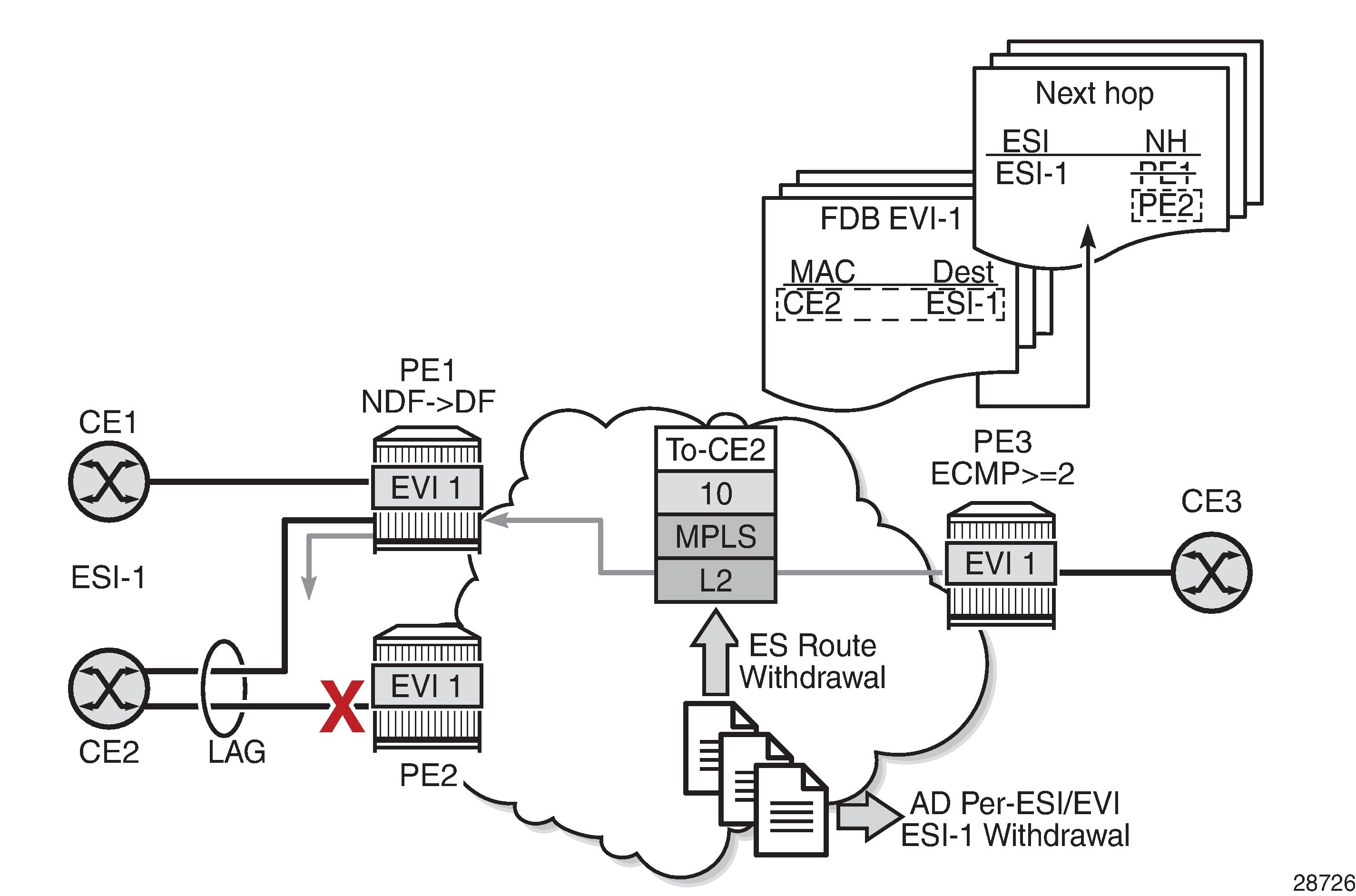
The unicast traffic behavior on PE3 is as follows.
PE3 can only forward MAC DA = CE2 to both PE1 and PE2 when the MAC advertisement route from PE1 or PE2 and the set of Ethernet AD per-ES routes and Ethernet AD per-EVI routes from PE1 and PE2 are active at PE3.
If there is a failure between CE2 and PE2, PE2 withdraws its set of Ethernet AD and ES routes, then PE3 forwards traffic destined for CE2 to PE1 only. PE3 does not need to wait for the withdrawal of the individual MAC address.
The same behavior would be followed if the failure had been at PE1.
If after (2), PE2 withdraws its MAC advertisement route, PE3 treats traffic to MAC DA = CE2 as unknown unicast, unless the MAC address had been previously advertised by PE1.
For BMU traffic, the following events trigger a DF election on a PE and only the DF forwards BMU traffic after the es-activation-timer expiration (if there was a transition from non-DF to DF):
reception of ES route update (local ES shutdown/no shutdown or remote route)
new AD-ES route update or withdrawal
new AD-EVI route update or withdrawal
local ES port or SAP or service shutdown
service-carving range change (affecting the evi)
multihoming mode change (single-active to all-active or all-active to single-active)
Logical Failures on Ethernet Segments and Black Holes
Black Hole Caused by SAP or Service Shutdown shows a black hole caused by a SAP or service shutdown.
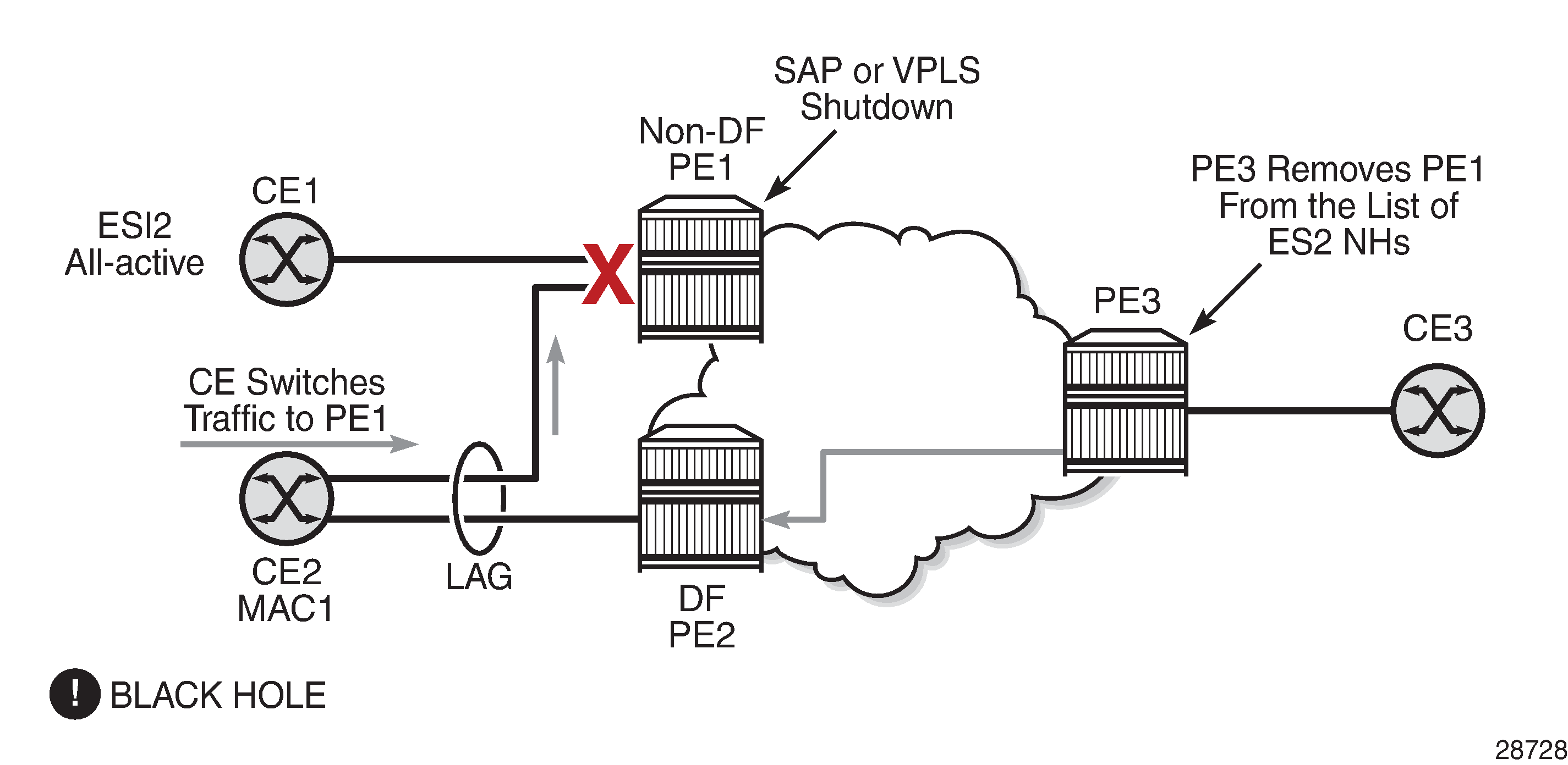
If an individual VPLS service is shutdown in PE1 (the example is also valid for PE2), the corresponding LAG SAP goes operationally down. This event triggers the withdrawal of the AD per-EVI route for that particular SAP. PE3 removes PE1 from its list of aliased next hops and PE2 takes over as DF (if it was not the DF already). However, this does not prevent the network from blackholing the traffic that CE2 switches to the link to PE1. Traffic sent from CE2 to PE2 or traffic from the rest of the CEs to CE2 is unaffected, so this situation is not easily detected on the CE.
The same result occurs if the ES SAP is administratively shutdown instead of the service.
Transient Issues Due to MAC Route Delays
Some situations may cause transient issues to occur, such as a transient packet duplication and a transient black hole. These are shown in Transient Issues Caused by Slow MAC Learning and explained below.
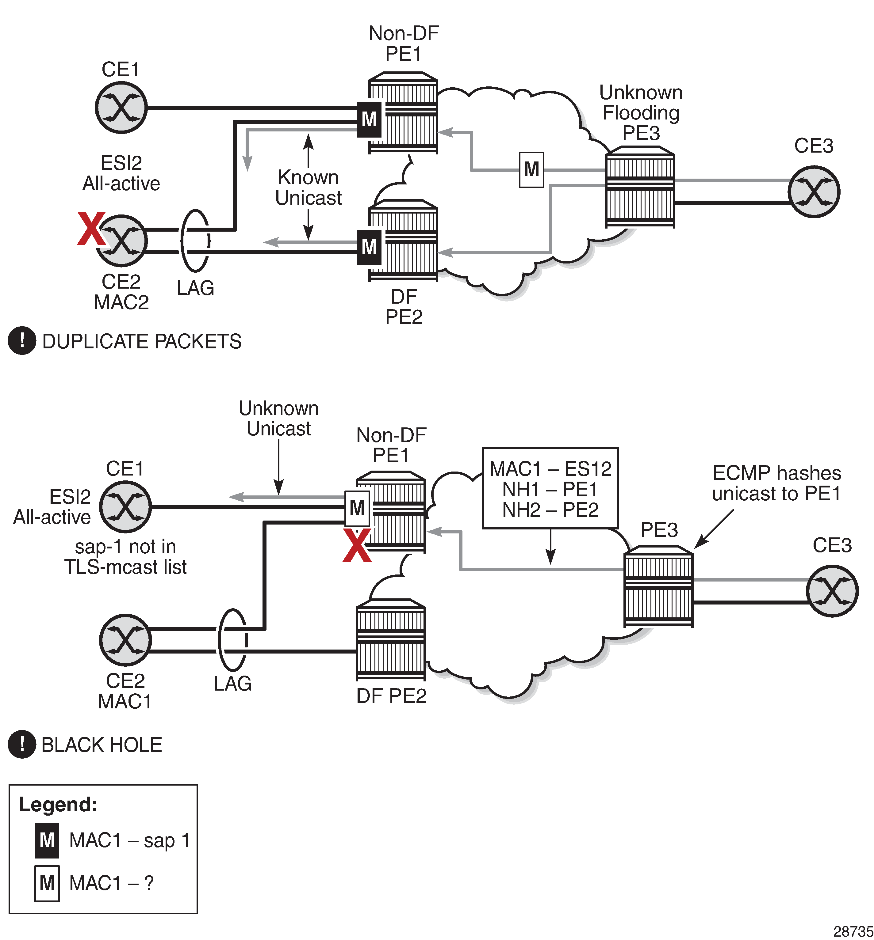
Transient packet duplication caused by delay in PE3 to learn MAC1:
This scenario is illustrated by the diagram at the top in Transient Issues Caused by Slow MAC Learning.
In an all-active multihoming scenario, if a specified MAC address (for example, MAC1), is not learned yet in a remote PE (for example, PE3) but it is known in the two PEs of the ES (for example, PE1 and PE2), the latter PEs might send duplicated packets to the CE.
This issue is solved by the use of the ingress-replication-bum-label command in PE1 and PE2. If the command is configured, PE1 and PE2 will know that the received packet is an unknown unicast packet; therefore, the non-DF (PE1) will not send the packets to the CE and there will not be duplication.
Even if the ingress-replication-bum-label command is not used, this is only a transient situation that is solved as soon as MAC1 is learned in PE3.
Transient black hole caused by delay in PE1 to learn MAC1:
This scenario is illustrated by the diagram at the bottom in Transient Issues Caused by Slow MAC Learning.
In an all-active multihoming scenario, MAC1 is known in PE3 and aliasing is applied to MAC1. However, MAC1 is not known yet in PE1, the non-DF for the ES. If PE3 hashing picks up PE1 as the destination for the aliased MAC1, the packets will be blackholed. This case is solved on the non-DF by not blocking unknown unicast traffic that arrives with a unicast label, which is possible if PE1 and PE2 are configured using ingress-replication-bum-label.
As soon as PE1 learns MAC1, the black hole is resolved even if ingress-replication-bum-label is not used.
EVPN Single-Active Multihoming
This section provides information on the following topics:
single-active multihoming service model
ES and DF Election Procedures (single-active multihoming)
backup PE function
network failures and convergence for single-active multihoming
The 7705 SAR supports single-active multihoming on access SAPs, LAG SAPs, and spoke SDPs for a specified VPLS service. For LAG SAPs, the CE is configured with a different LAG to each PE in the Ethernet segment (as opposed to a single LAG in all-active multihoming).
The following procedures support EVPN single-active multihoming for a specified Ethernet segment:
DF election
As in all-active multihoming, DF election in single-active multihoming determines the forwarding for BMU traffic from the EVPN network to the Ethernet segment CE. Also, in single-active multihoming, DF election determines the forwarding of any traffic (unicast and BMU) in any direction (to or from the CE).
backup PE
In single-active multihoming, the remote PEs do not perform aliasing to the PEs in the Ethernet segment. The remote PEs identify the DF based on the MAC routes and send the unicast flows for the Ethernet segment to the PE in the DF and program a backup PE as an alternative next hop for the remote ESI in case of failure, as shown in Backup PE for PE3.
Figure 13. Backup PE 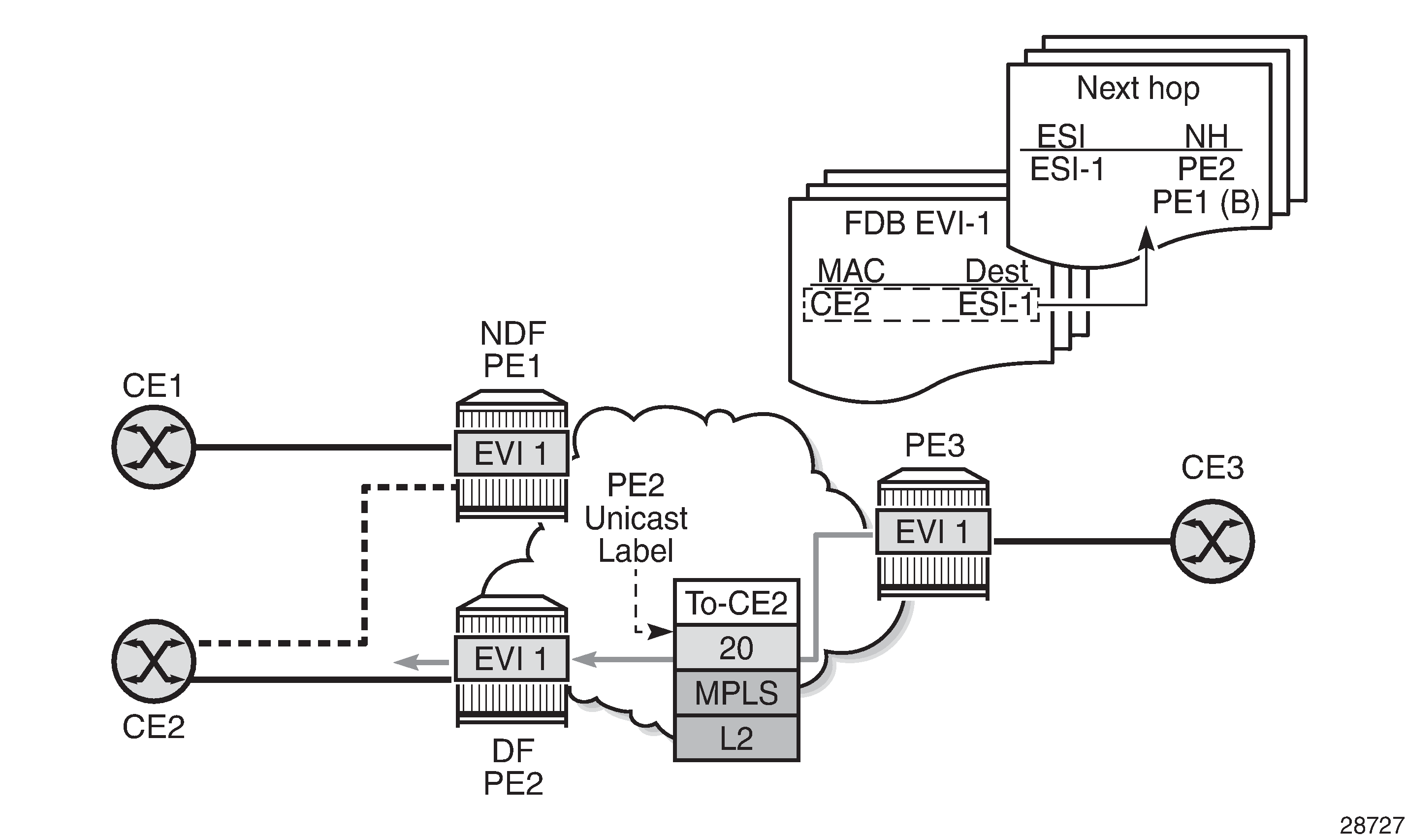
Single-Active Multihoming Service Model
The following is an example of PE1 configuration that provides single-active multihoming to CE2, as shown in Backup PE.
*A:PE1>config>service>system>bgp-evpn# info
----------------------------------------------
  route-distinguisher 1.1.1.1:0
  ethernet-segment "ESI2" create
    esi 01:12:12:12:12:12:12:12:12:12
    multi-homing single-active
    service-carving
    sdp 1
    no shutdown

*A:PE1>config>redundancy>bgp-evpn-multi-homing# info
----------------------------------------------
    boot-timer 120
    es-activation-timer 10

*A:PE1>config>service>vpls# info
----------------------------------------------
  description "evpn-mpls-service with single-active multihoming"
  bgp
  bgp-evpn
    evi 10
    mpls
      no shutdown
      auto-bind-tunnel resolution any
  spoke-sdp 1:1 create
  exit
The PE2 configuration for this scenario is as follows:
*A:PE2>config>service>system>bgp-evpn# info
----------------------------------------------
  route-distinguisher 1.1.1.1:0
  ethernet-segment "ESI2" create
    esi 01:12:12:12:12:12:12:12:12:12
    multi-homing single-active
    service-carving
    sdp 2
    no shutdown

*A:PE2>config>redundancy>bgp-evpn-multi-homing# info
----------------------------------------------
    boot-timer 120
    es-activation-timer 10

*A:PE2>config>service>vpls# info
----------------------------------------------
  description "evpn-mpls-service with single-active multihoming"
  bgp
  bgp-evpn
    evi 10
    mpls
      no shutdown
      auto-bind-tunnel resolution any
  spoke-sdp 2:1 create
  exit
In single-active multihoming, the non-DF PEs for a specified ESI block unicast and BMU traffic in both directions (upstream and downstream) on the object associated with the ESI. Single-active multihoming is similar to all-active multihoming with the following differences.
The Ethernet segment is configured for single-active: service>system>bgp-evpn>ethernet-segment>multi-homing single-active.
The advertisement of the ESI label in an AD per-ESI route is optional for single-active Ethernet segments. By default, the ESI label is used for single-active Ethernet segments. The user can control the no advertisement of the ESI label by using the following command: service>system>bgp-evpn>ethernet-segment>multi-homing single-active no-esi-label.
For single-active multihoming, the Ethernet segment can be associated with a port, SDP, or LAG ID, as shown in Backup PE, where:
a port is used for single-active SAP redundancy without the need for a LAG
an SDP is used for single-active spoke SDP redundancy
a LAG ID is used for single-active LAG redundancy
Note: In the last case (LAG ID for single-active LAG redundancy), the admin-key, system-id, and system-priority values must be different on the PEs that are part of the Ethernet segment.
For single-active multihoming, when the PE is non-DF for the service, the SAPs and spoke SDPs on the Ethernet segment are operationally down and show StandbyForMHProtocol as the reason.
From a service perspective, single-active multihoming can provide redundancy to CEs (multihomed devices (MHD)) or networks (multihomed networks (MHN)) with the following setup:
LAG with or without LACP
In this case, the multihomed ports on the CE are part of different LAGs (one LAG per multihomed PE is used in the CE).
regular Ethernet 802.1q/ad ports
In this case, the multihomed ports on the CE or network are not part of any LAG.
active-standby PWs
In this case, the multihomed CE or network is connected to the PEs through an MPLS network and an active/standby spoke SDP per service. The non-DF PE for each service uses the LDP PW status bits to signal that the spoke SDP is operationally down on the PE side.
ES and DF Election Procedures (single-active multihoming)
In all-active multihoming, the non-DF keeps the SAP operationally up, although it removes the SAP from the default flooding list. See the ES Discovery and DF Election Procedures (all-active multihoming) for more information. In the single-active multihoming implementation, the non-DF brings the SAP or SDP binding operationally down.
The following show commands display the status of the single-active Ethernet segment (ESI-7413) in the non-DF. The associated spoke SDP is operationally down and it signals PW status standby to the multihomed CE.
*A:PE1# show service system bgp-evpn ethernet-segment name "ESI-7413"

===============================================================================
Service Ethernet Segment
===============================================================================
Name                    : ESI-7413
Admin State             : Up                 Oper State         : Up
ESI                     : 01:74:13:00:74:13:00:00:74:13
Multi-homing            : singleActive       Oper Multi-homing  : singleActive
Source BMAC LSB         : <none>
Sdp Id                  : 4
ES Activation Timer     : 0 secs
Exp/Imp Route-Target    : target:74:13:00:74:13:00

Svc Carving             : auto
ES SHG Label            : 262141
===============================================================================


*A:PE1# show service system bgp-evpn ethernet-segment name "ESI-7413" evi 1
===============================================================================
EVI DF and Candidate List
===============================================================================
EVI           SvcId         Actv Timer Rem      DF  DF Last Change
-------------------------------------------------------------------------------
1             1             0                   no  06/11/2015 20:05:32
===============================================================================
===============================================================================
DF Candidates                           Time Added
-------------------------------------------------------------------------------
192.0.2.70                              06/11/2015 20:05:20
192.0.2.73                              06/11/2015 20:05:32
-------------------------------------------------------------------------------
Number of entries: 2
===============================================================================


*A:PE1# show service id 1 base
===============================================================================
Service Basic Information
===============================================================================
Service Id        : 1                   Vpn Id            : 0
Service Type      : VPLS
Name              : (Not Specified)
Description       : (Not Specified)

...<snip>...

-------------------------------------------------------------------------------
Service Access & Destination Points
-------------------------------------------------------------------------------
Identifier                               Type         AdmMTU  OprMTU  Adm  Opr
-------------------------------------------------------------------------------
sap:1/1/1:1                              q-tag        9000    9000    Up   Up
sdp:4:13 S(192.0.2.74)                   Spok         0       8978    Up   Down
===============================================================================
* indicates that the corresponding row element may have been truncated.


*A:PE1# show service id 1 all | match Pw
Local Pw Bits      : pwFwdingStandby
Peer Pw Bits       : None

*A:PE1# show service id 1 all | match Flag
Flags              : StandbyForMHProtocol
Flags              : None
Backup PE Function
A remote PE (PE3 in Backup PE) imports the AD routes per ESI, where the single-active flag is set. PE3 interprets the Ethernet segment as single-active if at least one PE sends an AD per-ESI route with the single-active flag set. MAC addresses for a specified service and ESI are learned from a single PE, that is, the DF for that ESI-EVI pair (per ESI, per EVI).
The remote PE installs both a single EVPN-MPLS destination (TEP, label) for a received MAC address and a backup next hop to the PE for which the AD per-ESI and per-EVI routes are received. For example, in the following show command output, 00:ca:ca:ba:ca:06 is associated with the remote Ethernet segment eES 01:74:13:00:74:13:00:00:74:13. That eES resolves to PE 192.0.2.73, which is the DF on the Ethernet segment.
*A:PE3# show service id 1 fdb detail
===============================================================================
Forwarding Database, Service 1
===============================================================================
ServId    MAC               Source-Identifier        Type     Last Change
                                                     Age
-------------------------------------------------------------------------------
1         00:ca:ca:ba:ca:02 sap:1/1/1:2              L/0      06/12/15 00:33:39
1         00:ca:ca:ba:ca:06 eES:                     Evpn     06/12/15 00:33:39
                            01:74:13:00:74:13:00:00:74:13
1         00:ca:fe:ca:fe:69 eMpls:                   EvpnS    06/11/15 21:53:47
                            192.0.2.69:262118
1         00:ca:fe:ca:fe:70 eMpls:                   EvpnS    06/11/15 19:59:57
                            192.0.2.70:262140
1         00:ca:fe:ca:fe:72 eMpls:                   EvpnS    06/11/15 19:59:57
                            192.0.2.72:262141
-------------------------------------------------------------------------------
No. of MAC Entries: 5
-------------------------------------------------------------------------------
Legend:  L=Learned O=Oam P=Protected-MAC C=Conditional S=Static
===============================================================================

*A:PE3# show service id 1 evpn-mpls
===============================================================================
BGP EVPN-MPLS Dest
===============================================================================
TEP Address     Egr Label     Num. MACs   Mcast           Last Change
                 Transport
-------------------------------------------------------------------------------
192.0.2.69      262118        1           Yes             06/11/2015 19:59:03
                ldp
192.0.2.70      262139        0           Yes             06/11/2015 19:59:03
                ldp
192.0.2.70      262140        1           No              06/11/2015 19:59:03
                ldp
192.0.2.72      262140        0           Yes             06/11/2015 19:59:03
                ldp
192.0.2.72      262141        1           No              06/11/2015 19:59:03
                ldp
192.0.2.73      262139        0           Yes             06/11/2015 19:59:03
                ldp
192.0.2.254     262142        0           Yes             06/11/2015 19:59:03
                bgp
-------------------------------------------------------------------------------
Number of entries : 7
-------------------------------------------------------------------------------
===============================================================================
===============================================================================
BGP EVPN-MPLS Ethernet Segment Dest
===============================================================================
Eth SegId                     TEP Address     Egr Label   Last Change
                                               Transport
-------------------------------------------------------------------------------
01:74:13:00:74:13:00:00:74:13 192.0.2.73      262140      06/11/2015 19:59:03
                                              ldp
-------------------------------------------------------------------------------
Number of entries : 1
-------------------------------------------------------------------------------
===============================================================================
If PE3 sees only two single-active PEs in the same ESI, the second PE is the backup PE. Upon receiving an AD per-ES or per-EVI route withdrawal for the ESI from the primary PE, PE3 starts sending the unicast traffic to the backup PE immediately.
If PE3 receives AD routes for the same ESI and EVI from more than two PEs, the PE does not install any backup route in the data path. Upon receiving an AD per-ES or per-EVI route withdrawal for the ESI, the PE flushes the MAC addresses associated with the ESI.
Network Failures and Convergence for Single-Active Multihoming
Single-Active Multihoming ES Failure shows the remote PE (PE3) behavior when there is an Ethernet segment failure.
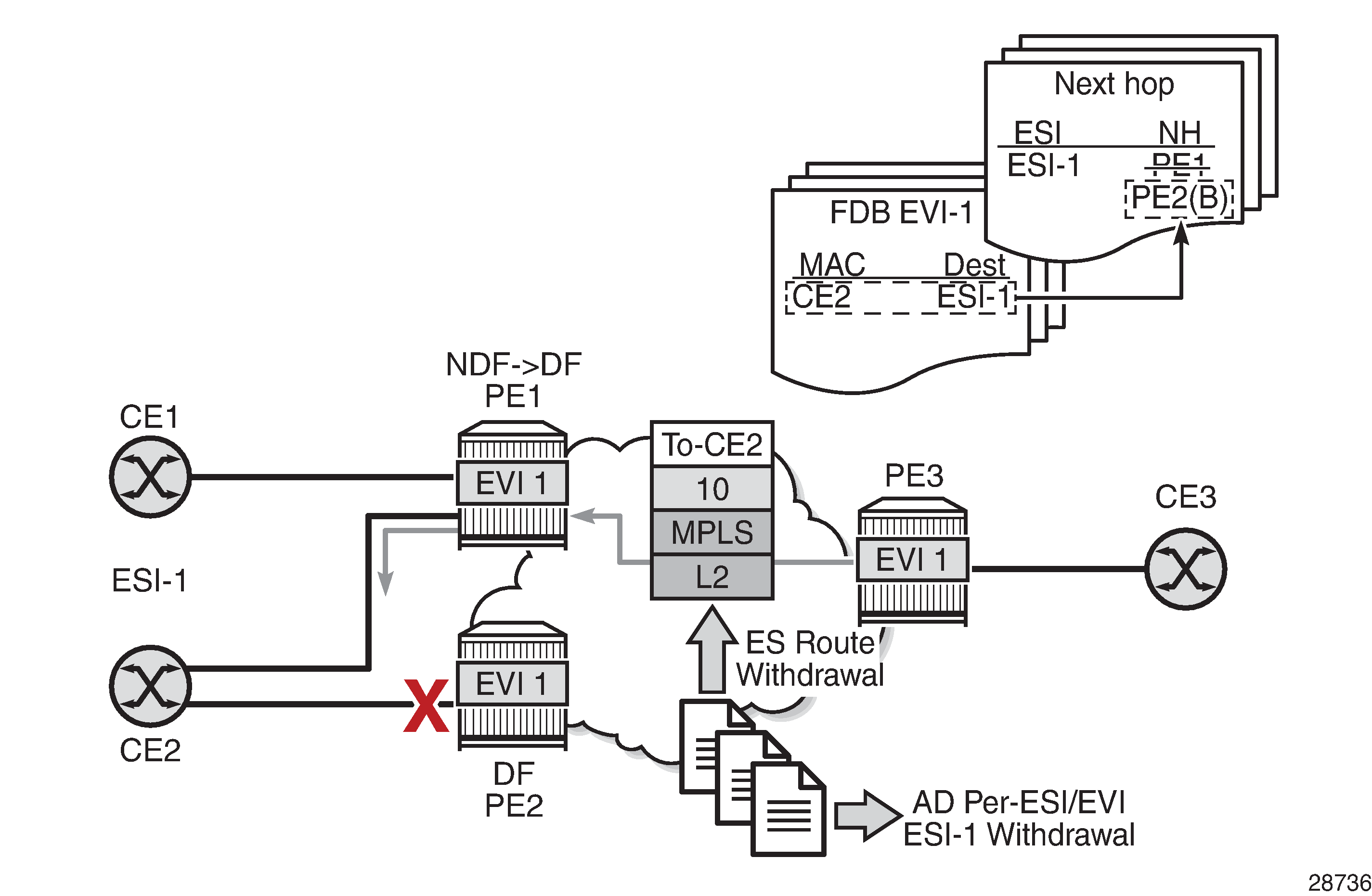
The PE3 behavior for unicast traffic is as follows.
PE3 forwards MAC DA = CE2 to PE2 when the MAC advertisement route came from PE2 and the set of Ethernet AD per-ES routes and Ethernet AD per-EVI routes from PE1 and PE2 are active at PE3.
If there is a failure between CE2 and PE2, PE2 withdraws its set of Ethernet AD and ES routes, then PE3 immediately forwards the traffic destined for CE2 to PE1 only (the backup PE). PE3 does not need to wait for the withdrawal of the individual MAC address.
After PE2 withdraws its MAC advertisement route, PE3 treats traffic to MAC DA = CE2 as unknown unicast, unless the MAC has been previously advertised by PE1.
Also, a DF election on PE1 is triggered. In general, a DF election is triggered by the same events as for all-active multihoming. In this case, the DF forwards traffic to CE2 when the es-activation-timer expiration occurs (the timer activates when there is a transition from non-DF to DF).
EVPN-VPWS for MPLS Tunnels
This section contains information about EVPN-VPWS for MPLS tunnels.
BGP-EVPN Control Plane for EVPN-VPWS
EVPN-VPWS uses route type 1 and route type 4; it does not use route types 2 or 3. EVPN-VPWS BGP Extensions shows the encoding of the required extensions for the Ethernet AD per-EVI routes. The encoding follows the guidelines described in draft-ietf-bess-evpn-vpws.
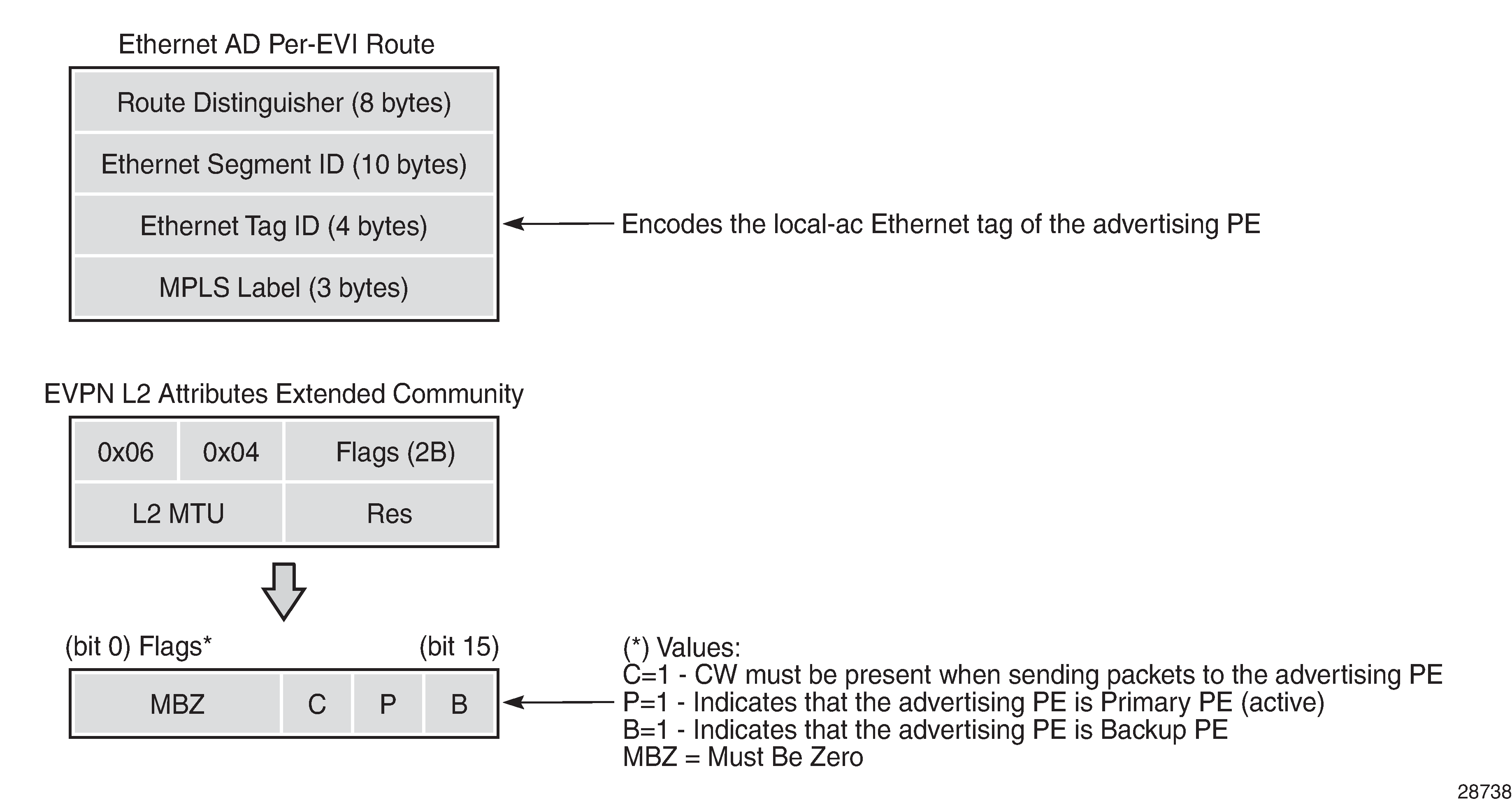
If the advertising PE has an access SAP-SDP or spoke SDP that is not part of an Ethernet segment (ES), the PE populates the fields of the AD per-EVI route with the following values.
Ethernet tag ID field is encoded with the value configured by the user in the service>epipe>bgp-evpn>local-ac-name>eth-tag value command.
RD and MPLS label values are encoded as specified in RFC 7432.
ESI is 0.
The route is sent along an EVPN Layer 2 attributes extended community, as specified in IETF draft-ietf-bess-evpn-vpws, where:
type and subtype are 0x06 and 0x04, as allocated by IANA
flag C is set if control-word is configured in the service
P- and B-flags are zero
Layer 2 MTU is encoded with service-mtu configured in the Epipe service
If the advertising PE has an access SAP-SDP or spoke SDP that is part of an ES, the AD per-EVI route is sent with the information described in the preceding list, with the following minor differences.
The ESI encodes the corresponding non-zero value.
The P- and B-flags are set in the following cases:
all-active multihoming
All PEs that are part of the ES always set the P-flag.
The B-flag is never set in the all-active multihoming ES case.
single-active multihoming
Only the DF PE sets the P-flag for an EVI and the remaining PEs send it as P=0.
Only the backup DF PE sets the B-flag.
If more than two PEs are present in the same single-active ES, the backup PE is the winner of a second DF election (excluding the DF). The remaining non-DF PEs send B=0.
Also, ES and AD per-ES routes are advertised and processed for the Ethernet segment, as described in RFC 7432. The ESI label sent with the AD per-ES route is used by BMU traffic on VPLS services; it is not used for Epipe traffic.
EVPN for MPLS Tunnels in Epipe Services
BGP-EVPN can be enabled in Epipe services with either SAPs or spoke SDPs at the access, as shown in EVPN-MPLS in Epipe Services.
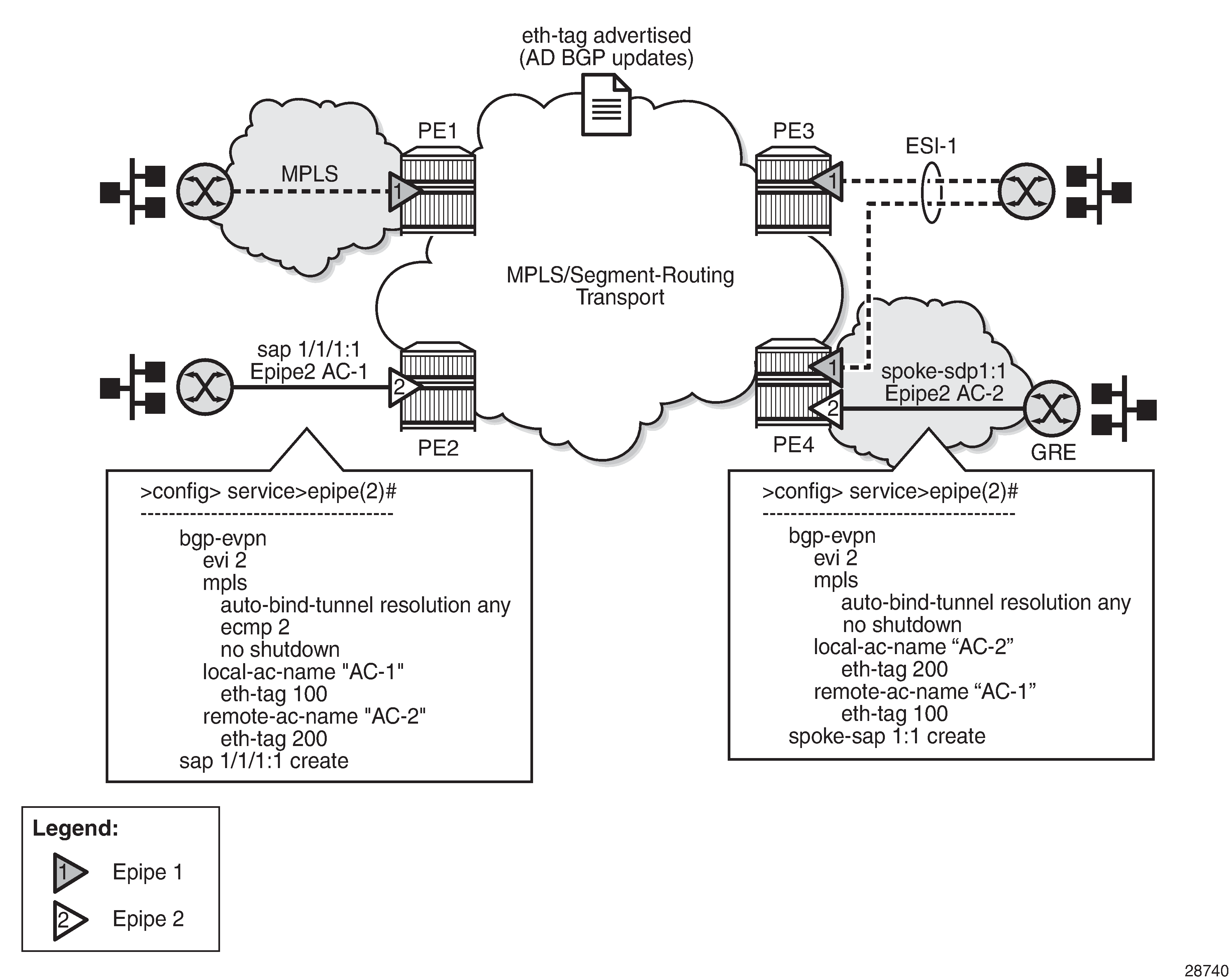
EVPN-VPWS is supported in MPLS networks that also run EVPN-MPLS in VPLS services. From a control plane perspective, EVPN-VPWS is a simplified point-to-point version of RFC 7432 for E-Line services for the following reasons.
-
EVPN-VPWS does not use inclusive multicast or MAC/IP routes.
-
Ethernet AD per-EVI routes are used to advertise the local attachment circuit identifiers at each side of the VPWS instance. The attachment circuit identifiers are configured as local and remote Ethernet tags. When an AD per-EVI route is imported and the Ethernet tag matches the configured remote Ethernet tag, an EVPN-MPLS destination is created for the Epipe.
In the following configuration example, Epipe 2 is an EVPN-VPWS service between PE2 and PE4 (as shown in EVPN-MPLS in Epipe Services):
PE2>config>service>epipe(2)#
-----------------------
  bgp-evpn
    evi 2
    mpls
      auto-bind-tunnel resolution any
      ecmp 2
      no shutdown
    local-ac-name "AC-1"
      eth-tag 100
    remote-ac-name "AC-2"
      eth-tag 200
  sap 1/1/1:1 create


PE4>config>service>epipe(2)#
-----------------------
  bgp-evpn
    evi 2
    mpls
      auto-bind-tunnel resolution any
      no shutdown
    local-ac-name "AC-2"
      eth-tag 200
    remote-ac-name "AC-1"
      eth-tag 100
 spoke-sdp 1:1
The following considerations apply to the configuration.
-
The evi value is used to auto-derive the route target or route distinguisher of the service. The evi values must be unique in the system regardless of the type of service they are assigned (Epipe or VPLS).
-
Support for the following bgp-evpn commands in Epipe services is the same as in VPLS services:
-
mpls>auto-bind-tunnel
-
mpls>control-word
-
mpls>entropy-label
-
mpls>force-vlan-vc-forwarding
-
mpls>shutdown
-
-
The following bgp-evpn commands identify the local and remote attachment circuits, with the configured eth-tag values encoded in the advertised and received AD Ethernet per-EVI routes:
-
local-ac-name ac-name
-
local-ac-name ac-name eth-tag tag-value, where tag-value is 1 to 16777215
-
remote-ac-name ac-name
-
remote-ac-name ac-name eth-tag tag-value, where tag-value is 1 to 16777215
Changes to the remote eth-tag value is allowed without shutting down bgp-evpn>mpls or the Epipe service. The local eth-tag value cannot be changed without using the bgp-evpn>mpls>shutdown command.
Both local and remote eth-tag values are mandatory to bring up the Epipe service.
-
EVPN-VPWS Epipes can also be configured with the following characteristics.
-
Access attachment circuits can be SAPs or spoke SDPs. Only manually configured spoke SDPs are supported; BGP-VPWS and endpoints are not supported. The vc-switching configuration is not supported on bgp-evpn enabled Epipes.
-
EVPN-VPWS Epipes support control-word and entropy-label.
When the bgp-evpn>mpls>control-word command is configured, the PE sets the C-bit in its AD per-EVI advertisement and sends the control word in the data path. In this case, the PE also expects the control word to be received. If there is a mismatch between the received control word and the configured control word, the system will not set up the EVPN destination. As a result, the service will not come up.
-
EVPN-VPWS Epipes can advertise the Layer 2 (service) MTU and check its consistency as follows.
-
The advertised MTU value is taken from the configured service-mtu in the Epipe service.
-
The received Layer 2 MTU is checked and compared with the local value. In case of a mismatch between the received MTU and the configured service-mtu, the system does not set up the EVPN destination. As a result, the service does not come up.
-
The system does not check the network port MTU value.
-
If the received Layer 2 MTU value is 0, the MTU is ignored.
-
Using A/S PW and MC-LAG with EVPN-VPWS Epipes
The use of active/standby (A/S) PW (for access spoke SDPs) and MC-LAG (for access SAPs) provides an alternative redundant solution for EVPN-VPWS that does not use the EVPN multihoming procedures described in IETF draft-ietf-bess-evpn-vpws. A/S PW and MC-LAG Support on EVPN-VPWS shows the use of both mechanisms in a single Epipe.
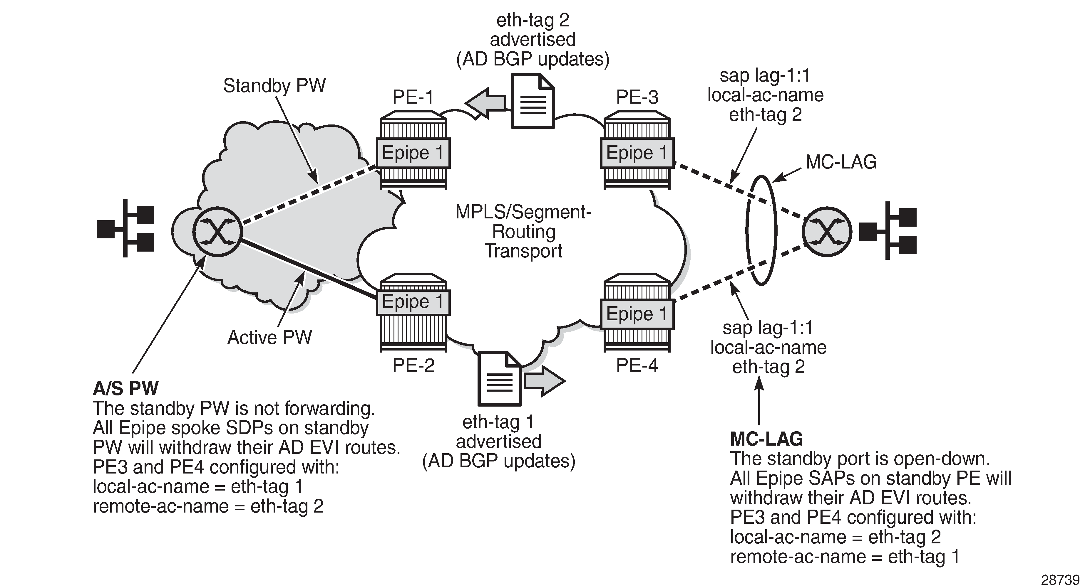
In A/S PW and MC-LAG Support on EVPN-VPWS, an A/S PW connects the CE to PE1 and PE2 (left-hand side of the diagram), and an MC-LAG connects the CE to PE3 and PE4 (right-hand side of the diagram). Because EVPN multihoming is not used, there are no AD per-ES routes or ES routes in this example. The redundancy is handled as follows.
PE1 and PE2 are configured with Epipe 1, where a spoke SDP connects the service in each PE to the access CE. The local-ac-name eth-tag is 1 and the remote-ac-name eth-tag is 2.
PE3 and PE4 are configured with Epipe 1, where each PE has a LAG SAP that belongs to a previously configured MC-LAG construct. The local-ac-name eth-tag is 2 and the remote-ac-name eth-tag is 1.
An endpoint and A/S PW is configured on the CE on the left-hand side of the diagram. PE1 and PE2 are able to advertise eth-tag 1 based on the operational status or the forwarding status of the spoke SDP.
For example, if PE1 receives a standby PW status indication from the CE and the previous status was forward, PE1 withdraws the AD EVI route for eth-tag 1. If PE2 receives a forward PW status indication and the previous status was standby or down, PE2 advertises the AD EVI route for eth-tag 1.
The user can configure MC-LAG for access SAPs using the configuration of PE3 and PE4 shown in A/S PW and MC-LAG Support on EVPN-VPWS. In this case, the MC-LAG determines which of the two chassis is active or standby.
If PE4 becomes the standby chassis, the entire LAG port is brought down. As a result, the SAP goes operationally down and PE4 withdraws any previous AD EVI route for eth-tag 2.
If PE3 becomes the active chassis, the LAG port becomes operationally up. As a result, the SAP and PE3 advertise the AD per-EVI route for eth-tag 2.
EVPN Multihoming for EVPN-VPWS Services
EVPN multihoming is supported for EVPN-VPWS Epipe services with the following considerations.
Single-active and all-active multihoming is supported for SAPs and spoke SDPs.
Ethernet segments (ESs) can be shared between the Epipe and VPLS services for LAGs, ports, and SDPs.
A split-horizon function is not required because there is no traffic between the DF and the non-DF for Epipe services. As a result, the ESI label is never used. For this reason, the ethernet-segment >multi-homing single-active no-esi-label command does not affect Epipe services.
The local Ethernet tag values must match on all PEs that are part of the same ES, regardless of the multihoming mode. The PEs in the ES use the AD per-EVI routes from the peer PEs to validate the PEs as DF election candidates for a specific EVI.
The DF election for Epipes that is defined in an all-active multihoming ES is not relevant because all PEs in the ES function in the same way.
All PEs send P=1 on the AD per-EVI routes.
All PEs can send upstream and downstream traffic, regardless of whether traffic is unicast, multicast, or broadcast (all traffic is treated as unicast in the Epipe services).
Therefore, the following tools command output shows ‟N/A” when all-active multihoming is configured.
*A:PE-2# tools dump service system bgp-evpn ethernet-segment "ESI-12" evi 6000 df
[03/18/2016 20:31:35] All Active VPWS - DF N/A
Aliasing is supported for traffic sent to an Ethernet segment destination. If ECMP is enabled on the ingress PE, per-service load balancing is performed to all PEs that advertise P=1. The PEs that advertise P=0 are not considered as next hops for an ES destination.
Although DF election is not relevant for Epipes in an all-active multihoming ES, it is essential for the following forwarding and backup functions in a single-active multihoming ES.
The PE elected as DF is the primary PE for the Ethernet segment in the Epipe. The primary PE unblocks the SAP or spoke SDP for upstream and downstream traffic. The remaining PEs in the ES bring their ES SAPs or spoke SDPs operationally down.
The DF candidate list is built from the PEs sending ES routes for the same ES and is pruned for a specific service, depending on the availability of the AD per-ES and per-EVI routes.
When the SAP or spoke SDPs (part of the ES) come up, the AD per-EVI routes are sent with P=B=0. The remote PEs do not send traffic at this stage.
The remote PEs do not start sending traffic until the DF election process is completed, the es-activation-timer has expired, and the PEs advertise AD per-EVI routes with P- and B-bits different from 0.
The backup PE function is supported as defined in IETF draft-ietf-bess-evpn-vpws. The primary PE, backup, or none status is signaled by the PEs (part of the same single-active multihoming ES) in the P- or B-flags of the EVPN Layer 2 attributes extended community. EVPN-VPWS Single-active Multihoming shows the advertisement and use of the primary, backup, or none indication by the PEs in the ES.
Figure 18. EVPN-VPWS Single-active Multihoming 
As specified in RFC 7432, the remote PEs in VPLS services have knowledge of the primary PE in the remote single-active ES, based on the advertisement of the MAC/IP routes (because only the DF learns and advertises MAC/IP routes).
Because there are no MAC or IP routes in EVPN-VPWS, the remote PEs can forward the traffic based on the P- and B-bits. The process is described in the following list (see the example in EVPN-VPWS Single-active Multihoming ).
The DF PE for an EVI (PE2 in EVPN-VPWS Single-active Multihoming ) sends P=1 and B=0.
For each ES or EVI, a second DF election is run among the PEs in the backup candidate list to elect the backup PE. The backup PE (PE3 in EVPN-VPWS Single-active Multihoming ) sends P=0 and B=1.
All remaining multihoming PEs (PE4 and PE5) send P=B=0.
At the remote PEs (PE1 in EVPN-VPWS Single-active Multihoming ), the P- and B-flags are used to identify the primary and backup PEs within the ES destination. The traffic is then sent to the primary PE, provided that it is active.
When a remote PE receives the withdrawal of an Ethernet AD per-ES (or EVI) route from the primary PE, the remote PE immediately switches the traffic to the backup PE for the affected EVIs.
The backup PE takes over immediately without waiting for the ES activation timer to expire and bring up its SAP or spoke SDP.
The bgp-evpn mpls ecmp setting also governs the forwarding in single-active multihoming, regardless of the single-active multihoming bit in the AD per-ES route received at the remote PE (PE1 in EVPN-VPWS Single-active Multihoming ).
PE1 always sends the traffic to the primary remote PE (the owner of the P=1 bit). If there are multiple primary PEs and ECMP > 1, PE1 will load-balance the traffic to all the primary PEs, regardless of the multihoming mode.
If the last primary PE withdraws its AD per-EVI or ES route, PE1 sends the traffic to the backup PE or PEs. If there are multiple backup PEs and ECMP > 1, PE1 load-balances the traffic to the backup PEs.
EVPN for MPLS Tunnels in r-VPLS Services
EVPN-MPLS and IP prefix advertisement (enabled by the ip-route-advertisement command) are fully supported in routed VPLS services. The following capabilities are supported in a service where bgp-evpn mpls is enabled:
r-VPLS with VRRP support on VPRN interfaces
r-VPLS support including ip-route-advertisement with regular interfaces
This includes the advertisement and process of IP prefix routes defined in IETF draft-ietf-bess-evpn-prefix-advertisement with the appropriate encoding for EVPN-MPLS.
r-VPLS support including ip-route-advertisement with evpn-tunnel interfaces
r-VPLS with IPv6 support on the VPRN IP interface
Overview
EVPN and MPLS can be enabled on VPLS or r-VPLS services on the 7705 SAR. While the EVPN-VPLS for MPLS Tunnels section focuses on the use of EVPN-MPLS Layer 2 services (that is, how EVPN-MPLS is configured in VPLS services), this section describes how EVPN-MPLS can be used to provide inter-subnet forwarding in r-VPLS and VPRN services. Although inter-subnet forwarding can be provided by regular r-VPLS and VPRN services, EVPN provides an efficient and unified way to populate forwarding databases (FDBs), address resolution protocol (ARP) tables, and routing tables using a single BGP address family. Inter-subnet forwarding in overlay networks would otherwise require data plane learning and the use of routing protocols on a per-VPRN basis.
The 7705 SAR solution for inter-subnet forwarding using EVPN is based on building blocks described in draft-sajassi-l2vpn-evpn-inter-subnet-forwarding and the use of the EVPN IP prefix routes (route type 5) as explained in draft-rabadan-l2vpn-evpnprefix-advertisement.
The IRB interface refers to an r-VPLS service bound to a VPRN IP interface.
EVPN-MPLS Multihoming and Passive VRRP
SAP-based and spoke SDP-based Ethernet segments are supported on r-VPLS services where bgp-evpn mpls is enabled.
EVPN-MPLS Multi-Homing in r-VPLS Services shows an example of EVPN-MPLS multi-homing in r-VPLS services, with the following assumptions.
There are two subnets for a specific customer (for example, EVI1 and EVI2 in EVPN-MPLS Multi-Homing in r-VPLS Services), and a VPRN is instantiated in all the PEs for efficient inter-subnet forwarding.
A backhaul r-VPLS with evpn-tunnel mode enabled is used in the core to interconnect all the VPRNs. EVPN IP prefix routes are used to exchange the prefixes corresponding to the two subnets.
An all-active ES is configured for EVI1 on PE1 and PE2.
A single-active ES is configured for EVI2 on PE3 and PE4.
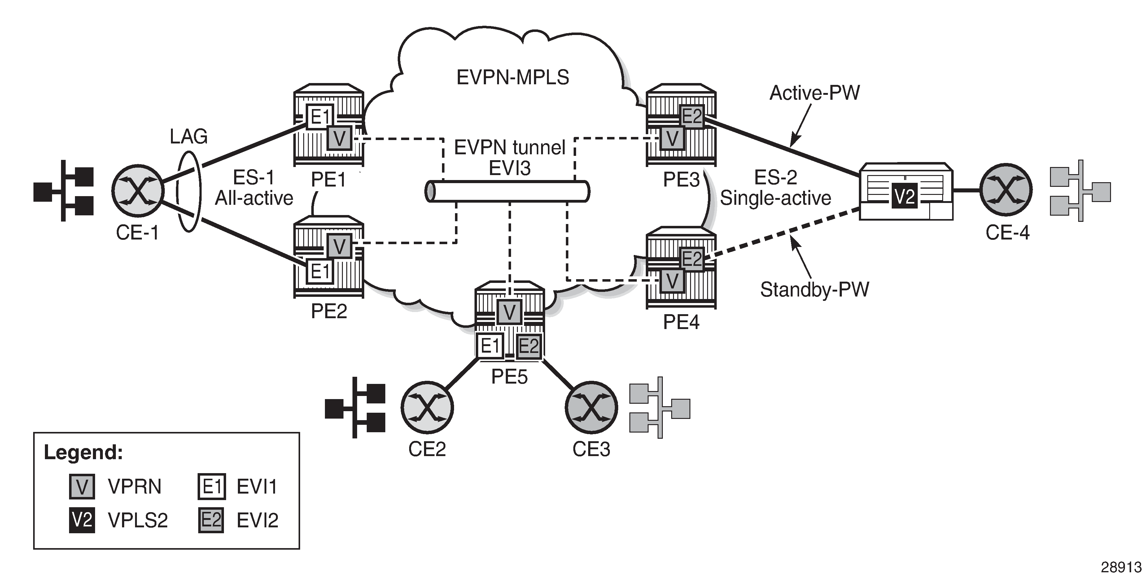
In EVPN-MPLS Multi-Homing in r-VPLS Services, the hosts connected to CE1 and CE4 could use regular VRRP for default gateway redundancy; however, this may not be the most efficient way to provide upstream routing.
For example, if PE1 and PE2 are using regular VRRP, the upstream traffic from CE1 may be hashed to the backup IRB VRRP interface instead of being hashed to the master interface. The same thing may occur for single-active multi-homing and regular VRRP for PE3 and PE4. The traffic from CE4 will be sent to PE3 although PE4 may be the VRRP master. In that case, PE3 will have to send the traffic to PE4 instead of routing it directly.
In both cases, unnecessary bandwidth between the PEs is used to get to the master IRB interface. In addition, VRRP scaling is limited if aggressive keepalive timers are used.
Because of these issues, passive VRRP is recommended as the best method when EVPN-MPLS multi-homing is used in combination with r-VPLS redundant interfaces.
Passive VRRP is a VRRP setting in which the transmission and reception of keepalive messages is completely suppressed, and therefore the VPRN interface always functions as the master. Passive VRRP is enabled by adding the passive keyword to the VRRP instance at creation time (passive mode cannot be enabled or disabled while the protocol is running), as shown in the following examples:
config service vprn interface vrrp virtual-router-id passive
config service vprn interface ipv6 vrrp virtual-router-id passive
For example, if PE1, PE2, and PE5 in EVPN-MPLS Multi-Homing in r-VPLS Services use passive VRRP, then even if each individual r-VPLS interface has a different MAC/IP address, because they share the same VRRP instance 1 and the same backup IP, the three PEs will own the same virtual MAC and virtual IP address (for example, 00-00-5E-00-00-01 and 10.0.0.254). The virtual MAC is auto-derived from 00-00-5E-00-00-VRID, as per RFC 3768. The following is the expected behavior when passive VRRP is used in this example.
All r-VPLS IRB interfaces for EVI1 have their own physical MAC/IP address; they also own the same default gateway virtual MAC and IP address.
All EVI1 hosts have a unique configured default gateway; for example, 10.0.0.254.
When CE1 or CE2 sends upstream traffic to a remote subnet, the packets are routed by the closest PE because the virtual MAC is always local to the PE.
For example, the packets from CE1 hashed to PE1 are routed at PE1. The packets from CE1 hashed to PE2 are routed directly at PE2.
Downstream packets (for example, packets from CE3 to CE1), are routed directly by the PE to CE1, regardless of the PE to which PE5 routed the packets.
For example, the packets from CE3 sent to PE1 are routed to CE1 at PE1. The packets from CE3 sent to PE2 are routed to CE1 at PE2.
In case of ES failure in one of the PEs, the traffic will be forwarded by the available PE.
For example, if the packets routed by PE5 arrive at PE1 and the link to CE1 is down, PE1 will send the packets to PE2. PE2 will forward the packets to CE1 even if the MAC source address of the packets matches the virtual MAC address of PE2. Virtual MAC addresses bypass the r-VPLS interface MAC protection.
The following list summarizes the advantages of using passive VRRP mode versus regular VRRP for EVPN-MPLS multi-homing in r-VPLS services.
Passive VRRP does not require multiple VRRP instances to achieve default gateway load balancing. Only one instance per r-VPLS—hence only one default gateway—is needed for all the hosts.
The convergence time for link or node failures is not impacted by the VRRP convergence because all the nodes in the VRRP instance are master routers.
Passive VRRP scales better than VRRP because it does not use keepalive or BFD messages to detect failures and allow the backup to take over.
MPLS Entropy Label
The router supports the MPLS entropy label (RFC 6790), allowing LSR nodes in a network to load-balance labeled packets in a much more granular fashion than allowed by simply hashing on the standard label stack. The entropy label can be enabled on BGP-EVPN services (VPLS and Epipe). See the ‟MPLS Entropy Labels” section in the 7705 SAR MPLS Guide for more information.
Preference-Based and Non-Revertive Designated Forwarder Election
The 7705 SAR supports the following service carving modes to elect a PE as the designated forwarder (DF) for a specific ES and service: auto, off, and manual. The manual mode supports the preference-based algorithm, which provides a user-controlled method for selecting a DF as described in draft-rabadan-bess-evpn-pref-df.
When an ES is configured to use the preference-based algorithm, the ES route is advertised with the DF election extended community attribute (sub-type 0x06). DF Election Extended Community Attribute shows the DF election extended community.
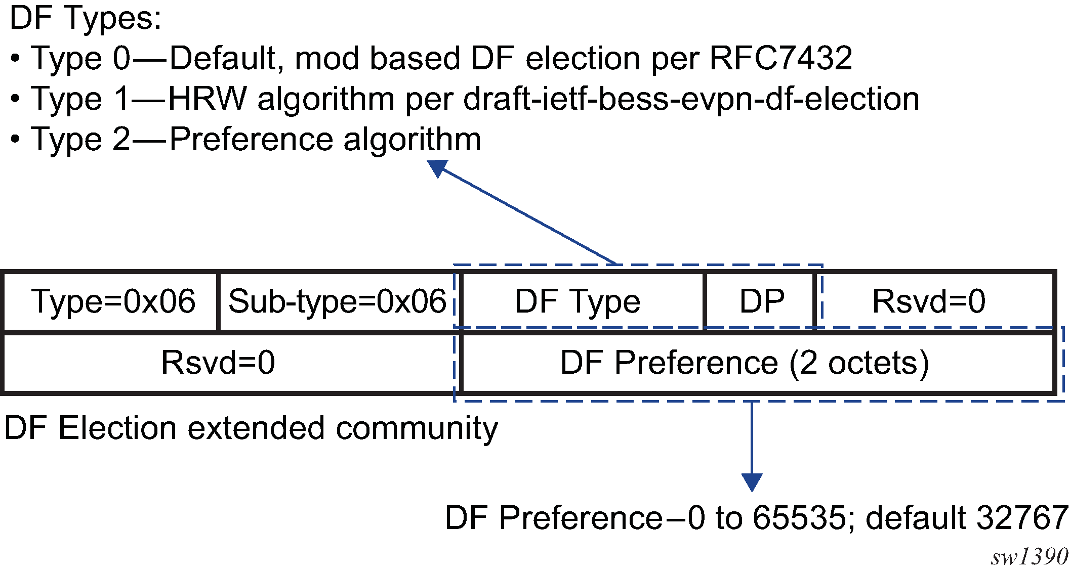
In the extended community, a DF Type 2 preference algorithm is advertised with a 2-byte preference value (32767) when the service-carving>manual>preference create command is configured, triggering preference-based DF election procedures. If any of the PEs exchanging the DF election extended community attribute for a particular ES and EVI do not have a DF Type of 2, all PEs will revert to using the service-carving mode auto election procedure. If there are more than four PEs involved in the preference-based DF election for a particular ES and EVI, the system prunes the ES candidate list to the four PEs with the lowest IP addresses.
The configured preference value is used to determine the DF PE when the preference-based DF election algorithm is run for each service EVI. The preferred DF is the PE with the highest or lowest preference value, depending on whether the highest-preference algorithm or the lowest-preference algorithm is used. By default, the highest-preference algorithm is used to elect a DF. If an EVI value or range of values is explicitly configured, the lowest-preference algorithm is used to elect a DF for those EVIs. When there are equal preference values, the DP bit is the first tiebreaker (a DP of 1 wins over a DP of 0) regardless of whether the highest-preference algorithm or lowest-preference algorithm is in use. The lowest PE IP address is the last-resort tiebreaker. If the preference value is not explicitly configured, the default value is used as the DF preference when the DF election extended community attribute is advertised.
The Don't Preempt (DP) bit is set when the non-revertive option is enabled. Setting the non-revertive option ensures that when a former DF PE comes back up after a failure, it does not take over from an existing active DF PE. By default, the non-revertive option is not set and when a former DF PE comes back after a failure, it will take over from an active DF PE.
The following CLI excerpt shows the commands to enable preference-based DF election on a specific ES:
config>service>system>bgp-evpn>ethernet-segment#
...
service-carving mode {manual | auto | off}
  service-carving manual
  [no] preference [create] [non-revertive]
         value value
         exit
  [no] evi evi [to evi]
# value 0..65535; default 32767
...
The service-carving command must be configured as manual in order to enter the preference context.
The preference command is supported on ESs regardless of the multihoming mode (single-active or all-active) or the service type (VPLS or Epipe). The preference value can be changed on an active ES without first shutting down the ES, making it possible to force a new DF for maintenance or other reasons.
The Don't Preempt (DP) bit in the DF election extended community attribute is set when the non-revertive option is enabled. Setting the non-revertive option ensures that when a former DF PE comes back up after a failure, it does not take over from an existing active DF PE. By default, the non-revertive option is not set and when a former DF PE comes back after a failure, it will take over from an active DF PE.
If the non-revertive option is configured, when the former DF comes back up after a failure and checks existing ES routes, it will advertise an operational preference and DP bit, which does not cause a DF switchover for the ES EVI values.
The following configuration example shows the use of the preference-based algorithm and non-revertive option in an ES defined in PE1 and PE2.
*A:PE-1>config>service>system>bgp-evpn# info
----------------------------------------------
 ethernet-segment "ES1" create
   esi 01:00:00:00:00:12:00:00:00:01
   service-carving manual
       preference non-revertive create
         value 10000
       exit
       evi 2001 to 4000
   exit
   multi-homing single-active
   port 1/1/1
   no shutdown

/* example of vpls 1 - similar config exists for evis 2-4000 */
*A:PE-1>config>service>vpls# info
----------------------------------------------
 vxlan vni 1 create
 exit
 bgp-evpn
   evi 1
   mpls
     ecmp 2
     auto-bind-tunnel
       resolution any
     exit
 sap 1/1/1:1 create
 no shutdown
----------------------------------------------
*A:PE-2>config>service>system>bgp-evpn# info
----------------------------------------------
 ethernet-segment "ES1" create
   esi 01:00:00:00:00:12:00:00:00:01
   service-carving manual
       preference non-revertive create
         value 5000
       exit
       evi 2001 to 4000
   exit
   multi-homing single-active
   port 1/1/1
   no shutdown

*A:PE-2>config>service>vpls# info
----------------------------------------------
 vxlan vni 1 create
 exit
 bgp-evpn
   evi 1
   mpls
     ecmp 2
     auto-bind-tunnel
       resolution any
     exit
 sap 1/1/1:1 create
 no shutdown
----------------------------------------------
Based on the configuration in the preceding example, the PE behaves as follows:
Assuming the ES is no shutdown on both PE1 and PE2, the PEs exchange ES routes, including the [Pref, DP-bit] in the DF election extended community attribute.
For EVIs 1 to 2000, PE2 is immediately promoted to non-designated forwarder (NDF); PE1 becomes the DF and once the es-activation-timer expires, PE1 brings up its SAP in EVIs 1 to 2000.
For EVIs 2001 to 4000, the result is the opposite and PE2 becomes the DF.
If port 1/1/1 on PE1 goes down, PE1 withdraws its ES route and PE2 becomes the DF for EVIs 1 to 2000.
When port 1/1/1 on PE1 comes back up, PE1 compares its ES1 preference with the preferences in the remote PEs in ES1. PE1 advertises the ES route with an ‟in-use operational” preference of 5000 and DP of 0. Because PE2's preference is the same as PE1's operational value but PE2's DP is 1, PE2 continues to be the DF for EVIs 1 to 4000.
Note: The DP bit is the tiebreaker when there are equal preference values, regardless of the choice of highest-preference or lowest-preference algorithm. The lowest PE-IP is the last-resort tiebreaker.PE1's ‟in-use” preference and DP will continue to be [5000,0] until one of the following conditions is true:
PE2 withdraws its ES route, in which case PE1 will re-advertise its administrative preference and DP [10000,DP=1]
The user changes PE1's preference configuration
General EVPN Topics
This section provides information about general topics related to EVPN.
BGP-EVPN MAC Mobility
EVPN defines a mechanism to allow the smooth mobility of MAC addresses. The 7705 SAR supports the MAC mobility extended community in MAC advertisement routes as follows.
The router honors and generates the SEQ (sequence) number in the MAC mobility extended community for MAC moves.
When a MAC address is EVPN-learned and there is an attempt for it to be learned locally, a BGP update is sent with the SEQ number changed to previous_SEQ+1, except when the MAC duplication num-moves value is reached.
If the sequence number is 0 or if the extended community received in the type 2 MAC/IP advertisement route is not included, then the sequence number is interpreted as 0.
For MAC mobility, the following MAC address selection procedure is followed.
If a PE has two or more active remote EVPN routes for the same MAC address, the highest SEQ number is selected. The tiebreaker is the lowest IP address (BGP next-hop IP address).
If a PE has two or more active EVPN routes and the PE is the originator of one of the routes, the highest SEQ number is selected. The tiebreaker is the lowest IP address (BGP next-hop IP address of the remote route is compared to the local system address).
BGP-EVPN MAC Duplication
EVPN defines a mechanism to protect the EVPN service from control plane churn as a result of loops or accidental duplicated MAC addresses. The 7705 SAR supports an enhanced version of this procedure as described in this section.
A situation may arise where the same MAC address is learned by different PEs in the same VPLS because of two or more hosts being incorrectly configured with the same (duplicate) MAC address. In this situation, the traffic originating from these hosts triggers continuous MAC moves among the PEs attached to these hosts. It is important to recognize this situation and avoid incrementing the sequence number in the MAC mobility attribute to infinity.
To remedy the above situation, a router that detects a MAC mobility event by way of local learning starts a window minutes timer (default value is 3 minutes). and if the router detects num-moves value before the timer expires (default value is 5 moves), the router concludes that a duplicate MAC situation has occurred. The router then alerts the operator with a trap message. The offending MAC address can be viewed using the show>service>id n >bgp-evpn command:
10 2018/01/14 01:00:22.91 UTC MINOR: SVCMGR #2331 Base
"VPLS Service 1 has MAC(s)detected as duplicates by EVPN mac-duplication detection."

# show service id 1 bgp-evpn
===============================================================================
BGP EVPN Table
===============================================================================
MAC Advertisement  : Enabled            Unknown MAC Route  : Disabled
VXLAN Admin Status : Disabled           Creation Origin    : manual
MAC Dup Detn Moves : 5                  MAC Dup Detn Window: 3
MAC Dup Detn Retry : 9                  Number of Dup MACs : 1
-------------------------------------------------------------------------------
Detected Duplicate MAC Addresses             Time Detected
-------------------------------------------------------------------------------
00:00:00:00:00:12                            01/14/2014 01:00:23
-------------------------------------------------------------------------------
===============================================================================
After detecting the duplicate address, the router stops sending and processing any BGP MAC advertisement routes for that MAC address until one of the following occurs:
the MAC address is flushed due to a local event (such as a SAP or SDP binding associated with the MAC address failing) or the reception of a remote update with a higher SEQ number (due to a MAC address flush at the remote router)
the retry minutes timer expires, which flushes the MAC address and restarts the process
The num-moves and window values are configurable to allow for the required flexibility in different environments. In scenarios where bgp>rapid-update evpn is configured, the operator may want to configure a shorter window timer than in scenarios where BGP updates are sent every default min-route-advertisement interval.
The MAC duplication parameters can be configured per VPLS service under the bgp-evpn>mac-duplication context, as shown in the following example:
*A:DGW1>config>service>vpls>bgp-evpn# info
----------------------------------------------
       mac-advertisement
       mac-duplication
         detect num-moves 5 window 3
         retry 9
       exit
Conditional Static MAC and Protection
RFC 7432 defines the use of the sticky bit in the MAC mobility extended community to signal static MAC addresses. These addresses must be protected in case there is an attempt to dynamically learn them from a different source.
On the 7705 SAR, any conditional static MAC address is advertised by BGP-EVPN as a static address—that is, with the sticky bit set. An example of the configuration of a conditional static MAC address is shown below:
*A:PE63>config>service>vpls# info
----------------------------------------------
...
            sap 1/1/1:1000 create
            exit
            static-mac
                mac 00:ca:ca:ca:ca:00 create sap 1/1/1:1000 monitor fwd-status
            exit
            no shutdown

*A:PE64# show router bgp routes evpn mac hunt mac-address 00:ca:ca:ca:ca:00
...
===============================================================================
BGP EVPN Mac Routes
===============================================================================
Network        : 0.0.0.0/0
Nexthop        : 192.0.2.63
From           : 192.0.2.63
Res. Nexthop   : 192.168.19.1
Local Pref.    : 100                    Interface Name : NotAvailable
Aggregator AS  : None                   Aggregator     : None
Atomic Aggr.   : Not Atomic             MED            : 0
AIGP Metric    : None
Connector      : None
Community      : target:65000:1000     mac-mobility:Seq: 0/Static
Cluster        : No Cluster Members
Originator Id  : None                   Peer Router Id : 192.0.2.63
Flags          : Used  Valid  Best  IGP
Route Source   : Internal
AS-Path        : No As-Path
EVPN type      : MAC
ESI            : 0:0:0:0:0:0:0:0:0:0    Tag            : 1063
IP Address     : ::                     RD             : 65063:1000
Mac Address    : 00:ca:ca:ca:ca:00      Mac Mobility   : Seq:0
Neighbor-AS    : N/A
Source Class   : 0                      Dest Class     : 0
-------------------------------------------------------------------------------
Routes : 1
===============================================================================
Local static MAC addresses or remote MAC addresses with sticky bit are considered to be protected. A packet entering a SAP or SDP binding is discarded if its source MAC address matches one of the protected MAC addresses.
Blackhole MAC
A blackhole MAC is a local FDB record. It is similar to a conditional static MAC; it is associated with a black hole—similar to a VPRN blackhole static route in VPRNs—instead of a SAP or SDP binding. A blackhole MAC can be added by using the following CLI command:
config>service>vpls>static-mac>mac ieee-address [create] black-hole
The static blackhole MAC can have security applications for certain MAC addresses (for example, replacement of MAC filters).
For example, when a specified blackhole MAC is added to a service (static-mac mac 00:00:ca:fe:ca:fe create black-hole), the following behavior occurs.
The configured MAC address is created as a static MAC address with a ‟black-hole” source identifier.
    *A:PE1# show service id 1 fdb detail
    ===============================================================================
    Forwarding Database, Service 1
    ===============================================================================
    ServId    MAC               Source-Identifier        Type     Last Change
                                                        Age
    -------------------------------------------------------------------------------
    1         00:ca:ca:ba:ca:01 eES:                     Evpn      06/29/15 23:21:34
                                01:00:00:00:00:71:00:00:00:01
    1         00:ca:ca:ba:ca:06 eES:                     Evpn      06/29/15 23:21:34
                                01:74:13:00:74:13:00:00:74:13
    1         00:ca:00:00:00:00 sap:1/1/1:2              CStatic:P 06/29/15 23:20:58
    1         00:ca:fe:ca:fe:00 black-hole               CStatic:P 06/29/15 23:20:00
    1         00:ca:fe:ca:fe:69 eMpls:                   EvpnS:P   06/29/15 20:40:13
                                192.0.2.69:262133
    -------------------------------------------------------------------------------
    No. of MAC Entries: 5
    -------------------------------------------------------------------------------
    Legend:  L=Learned O=Oam P=Protected-MAC C=Conditional S=Static
    ===============================================================================
After the blackhole MAC has been successfully added to the FDB, it is treated like any other protected MAC. The blackhole MAC is added as protected (CStatic:P) and advertised in EVPN as static.
After the blackhole MAC has been successfully added to the FDB, any frame arriving at any SAP, SDP binding, or EVPN endpoint with a MAC DA that is equal to the blackhole MAC is discarded.
CFM Interaction with EVPN Services
Ethernet connectivity and fault management (ETH-CFM) allows the operator to validate and measure Ethernet Layer 2 services using standard IEEE 802.1ag and ITU-T Y.1731 protocols. Each tool performs a unique function and adheres to that tool’s specific PDU and frame format and the associated rules governing the transmission, interception, and process of the PDU. For more information, see the ‟ETH OAM Capabilities” section in the 7705 SAR OAM and Diagnostics Guide.
EVPN provides powerful solution architectures. ETH-CFM is supported in various Layer 2 EVPN architectures. Because the destination Layer 2 MAC address (unicast or multicast) is ETH-CFM tool-dependent (that is, ETH-CC is sent as a Layer 2 multicast and ETH-DM is sent as a Layer 2 unicast), the ETH-CFM function is allowed to multicast and broadcast to the virtual EVPN connections. The Maintenance Endpoint (MEP) does not populate the local Layer 2 MAC address forwarding database (FDB) with the MAC address related to the MEP. This means that the 48-bit IEEE MAC address is not exchanged with peers and all ETH-CFM frames are broadcast across all virtual connections. To prevent the flooding of unicast packets and allow the remote forwarding databases to learn the remote MEP Layer 2 MAC addresses, the command cfm-mac-advertisement must be configured under the config>service>vpls>bgp-evpn context. This allows the MEP Layer 2 IEEE MAC addresses to be exchanged with peers. This command tracks configuration changes and sends the required updates via the EVPN notification process related to a change.
Up MEP and Down MEP creation is supported on SAP connections and on spoke and mesh SDP connections in the EVPN service. There is no support for the creation of ETH-CFM MEPs on the virtual connection.
When MEPs are used in combination with EVPN multihoming, the following must be considered:
Behavior of operationally down MEPs on SAPs or SDPs with EVPN multihoming:
all-active multi-homing: in this case, no ETH-CFM is expected to be used because the SAPs or SDPs on the PEs are operationally up and active. However, the CE has a single LAG and responds as though it is connected to a single system. In addition, cfm-mac-advertisement can lead to traffic loops in all-active multihoming.
single-active multi-homing: operationally down MEPs defined on single-active Ethernet segment SAPs or SDPs do not send any CCMs when the PE is a non-DF for the Ethernet segment and fault-propagation is configured
Behavior of operationally up MEPs on Ethernet segment SAPs or SDPs with EVPN multihoming:
all-active multi-homing: operationally up MEPs defined on non-DF Ethernet segment SAPs or SDPs can send CFM packets. However, they cannot receive CCMs (the SAP or SDP is removed from the default multicast list) or unicast CFM packets (because the MEP MAC address is not installed locally in the FDB, unicast CFM packets are treated as unknown and are not sent to the non-DF MEP).
single-active multi-homing: operationally up MEPs are able to send or receive CFM packets normally
Due to the above considerations, the use of ETH-CFM in EVPN multihomed SAPs or SDPs is only recommended on operationally down MEPs and single-active multihoming. ETH-CFM is used in this case to notify the CE of the DF or non-DF status.
BGP and EVPN Route Selection for EVPN Routes
When two or more EVPN routes are received at a PE, BGP route selection typically takes place when the route key or the routes are equal. When the route key is different but the PE must make a selection (for instance, the same MAC address is advertised in two routes with different RDs), BGP hands over the routes to EVPN and the EVPN application performs the selection.
EVPN and BGP selection criteria are described below.
EVPN route selection for MAC routes
When two or more routes with the same mac-length and mac but different route key are received, BGP hands the routes over to EVPN. EVPN selects the route based on the following tiebreaking order:
Conditional static MAC addresses (local protected MAC addresses)
EVPN static MAC addresses (remote protected MAC addresses)
Data plane learned MAC addresses (regular learning on SAPs and SDP bindings)
EVPN MAC addresses with higher SEQ number
Lowest IP address (next-hop IP address of the EVPN NLRI)
Lowest Ethernet tag (the tag will be 0 for MPLS)
Lowest RD
BGP route selection:
The regular BGP route selection is followed.
Interaction of EVPN and Other Features
This section contains information about the following topics:
Interaction of EVPN-MPLS with Existing VPLS Features
When enabling existing VPLS features in an EVPN-MPLS service, the following must be considered.
EVPN-MPLS is only supported in regular VPLS. Other VPLS types, such as management VPLS (mVPLS), are not supported with EVPN-MPLS.
In general, no router-generated control packets are sent to the EVPN destination bindings, except for ETH-CFM for EVPN-MPLS.
STP and mVPLS services:
STP can be configured in BGP-EVPN services. BPDUs are not sent over the EVPN bindings.
The bgp-evpn command is blocked in mVPLS services; however, a separate mVPLS service can manage a SAP or spoke SDP in a BGP-EVPN service.
The mac-move command can be used in BGP-EVPN VPLS services for SAPs and SDP bindings; however, the MAC addresses being learned through BGP-EVPN will not be considered.
Note: The MAC duplication function already provides protection against MAC moves between EVPN and SAPs and SDP bindings.The disable-learning command and other FDB-related tools only work for data-plane learned MAC addresses.
The mac-protect command cannot be used in conjunction with EVPN.
Note: EVPN provides its own protection mechanism for static MAC addresses.MAC OAM tools are not supported for BGP-EVPN services, including the following commands: mac-ping, mac-trace, mac-populate, mac-purge, and cpe-ping.
SAPs and SDP bindings that belong to a specified ES but are configured on non-BGP-EVPN MPLS-enabled VPLS or Epipe services are kept operationally down with the StandbyForMHProtocol flag.
CPE ping is not supported for EVPN services. CPE ping packets are not sent over EVPN destinations.
Other functions not supported in conjunction with the bgp-evpn command include:
endpoints and attributes
MLD snooping and attributes
BPDU translation
MAC pinning
Routing Policies for BGP-EVPN IP Prefixes
BGP routing policies are supported for IP prefixes imported or exported through BGP-EVPN.
When applying routing policies to control the distribution of prefixes between EVPN and IP-VPN, the user must consider that both families are separate as far as BGP is concerned, and when prefixes are imported in the VPRN routing table, the BGP attributes are lost to the other family. The use of route tags allows the controlled distribution of prefixes across the two families.
IP-VPN Import and EVPN Export BGP Workflow shows an example of how VPN-IPv4 routes are imported into the routing table manager (RTM) and then passed to EVPN for processing.
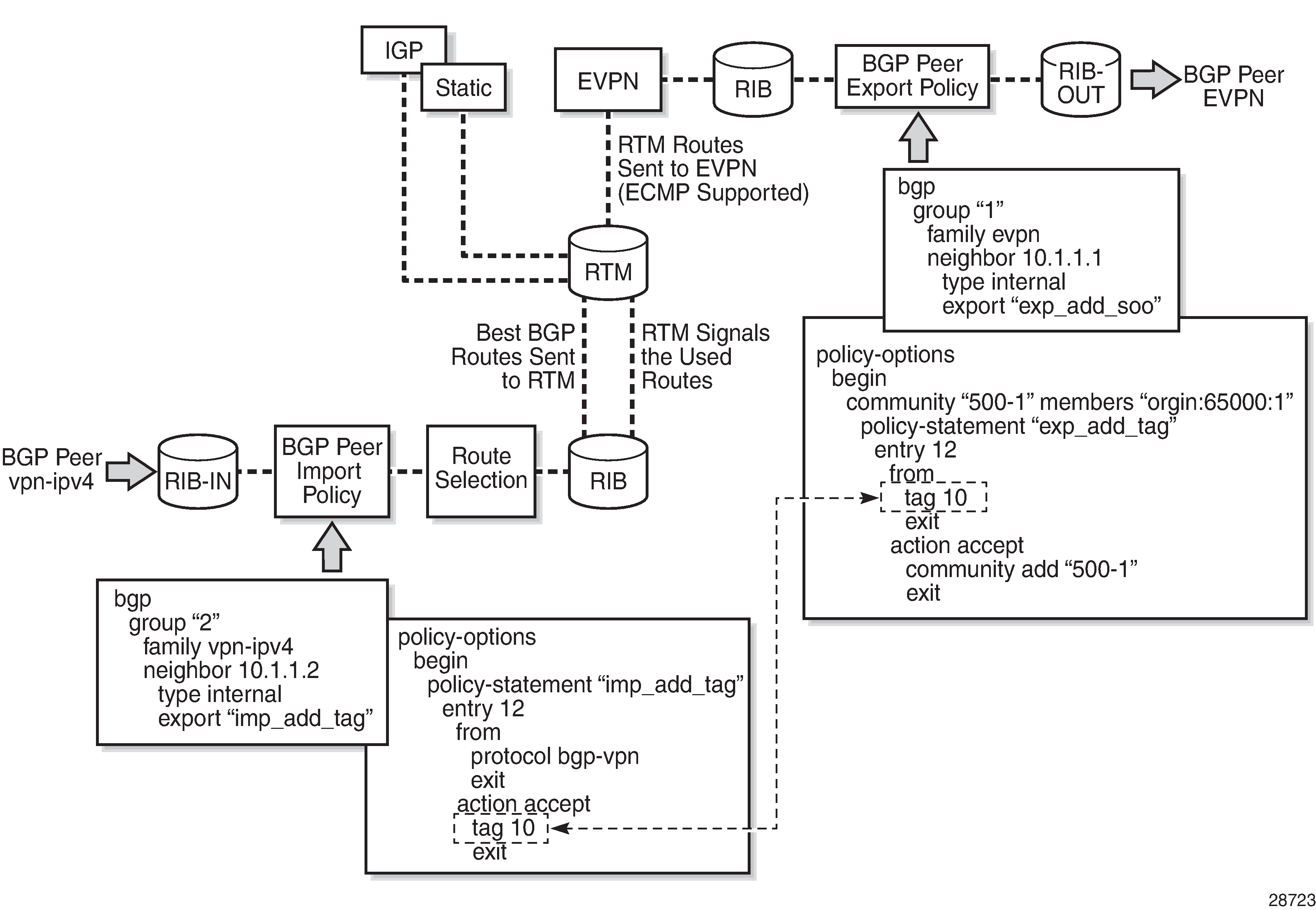
Policy tags can be used to match EVPN IP prefixes that were learned not only from BGP VPN-IPv4 but also from other routing protocols. The tag range supported for each protocol is different:
<tag>  : accepts in decimal or hex
        [0x1..0xFFFFFFFF]H (for OSPF and IS-IS)
        [0x1..0xFFFF]H (for RIP)
        [0x1..0xFF]H (for BGP)
EVPN Import and IP-VPN Export BGP Workflow shows an example of the reverse workflow: routes imported from EVPN and exported from RTM to BGP VPN-IPv4.
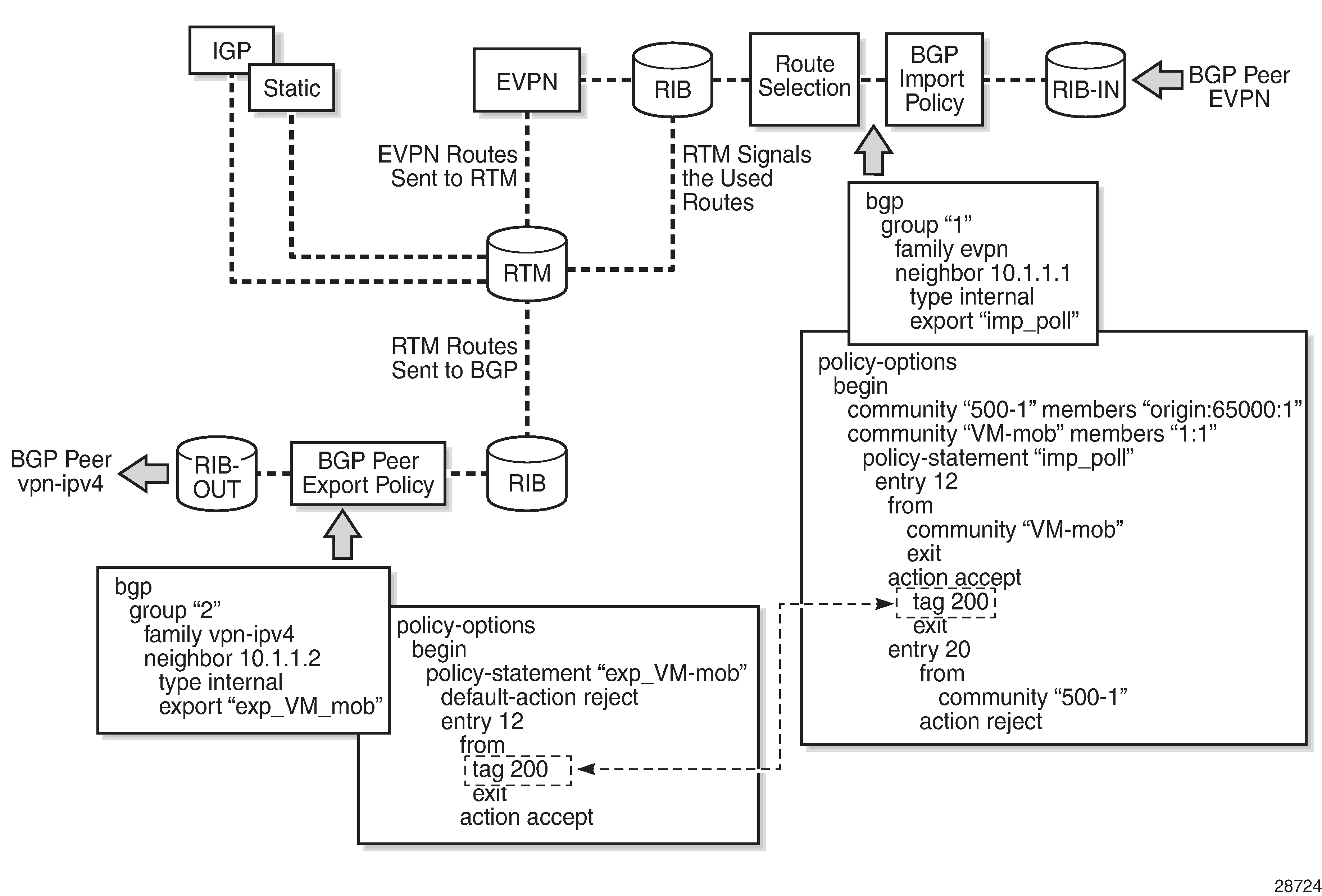
The policy behavior for EVPN IP prefixes is summarized in the following statements:
for EVPN prefix routes received and imported in RTM:
policy entries can match on communities and add tags. This works at the peer level or at the vsi-import level.
policy entries can match on family evpn
for exporting RTM to EVPN prefix routes:
policy entries can match on tags and based on that, add communities, accept, or reject. This works at the peer level or the virtual switch instance (VSI) export level.
Policy entries can add tags for static routes, RIP, OSPF, IS-IS, and BGP that can then be matched on the BGP peer export policy or VSI export policy for EVPN prefix routes.
Configuring an EVPN Service With CLI
This section provides examples for configuring EVPN multihoming for VPLS services using the command line interface:
EVPN All-Active Multihoming Configuration Example
This section shows a configuration example for three 7705 SAR PEs, with the following assumptions.
PE-1 and PE-2 are multihomed to CE-12, which uses a LAG to connect to the network. CE-12 is connected to LAG SAPs configured in an all-active multihoming Ethernet segment.
PE-3 is a remote PE that performs aliasing for traffic destined for the CE-12.
The following configuration excerpt applies to a VPLS-1 on PE-1 and PE-2 and includes the corresponding ethernet-segment and lag commands.
A:PE1# configure lag 1
A:PE1>config>lag# info
----------------------------------------------
        mode access
        encap-type dot1q
        port 1/1/2
        lacp active administrative-key 1 system-id 00:00:00:00:69:72
        no shutdown
----------------------------------------------

A:PE1>config>lag# /configure service system bgp-evpn
A:PE1>config>service>system>bgp-evpn# info
----------------------------------------------
                route-distinguisher 192.0.2.69:0
                ethernet-segment "ESI-71" create
                    esi 0x01000000007100000001
                    es-activation-timer 10
                    service-carving
                        mode auto
                    exit
                    multi-homing all-active
                    lag 1
                    no shutdown
                exit
----------------------------------------------

A:PE1>config>service>system>bgp-evpn# /configure service vpls 1
A:PE1>config>service>vpls# info
----------------------------------------------
            bgp
            exit
            bgp-evpn
                cfm-mac-advertisement
                evi 1
                exit
                mpls
                    ingress-replication-bum-label
                    auto-bind-tunnel
                        resolution any
                    exit
                    no shutdown
                exit
            exit
            stp
                shutdown
            exit
            sap lag-1:1 create
            exit
            no shutdown
----------------------------------------------
A:PE2# configure lag 1
A:PE2>config>lag# info
----------------------------------------------
        mode access
        encap-type dot1q
        port 1/1/3
        lacp active administrative-key 1 system-id 00:00:00:00:69:72
        no shutdown
----------------------------------------------

A:PE2>config>lag# /configure service system bgp-evpn
A:PE2>config>service>system>bgp-evpn# info
----------------------------------------------
                route-distinguisher 192.0.2.72:0
                ethernet-segment "ESI-71" create
                    esi 0x01000000007100000001
                    es-activation-timer 10
                    service-carving
                        mode auto
                    exit
                    multi-homing all-active
                    lag 1
                    no shutdown
                exit
----------------------------------------------

A:PE2>config>service>system>bgp-evpn# /configure service vpls 1
A:PE2>config>service>vpls# info
----------------------------------------------
            bgp
            exit
            bgp-evpn
                cfm-mac-advertisement
                evi 1
                exit
                mpls
                    ingress-replication-bum-label
                    auto-bind-tunnel
                        resolution any
                    exit
                    no shutdown
                exit
            exit
            stp
                shutdown
            exit
            sap lag-1:1 create
            exit
            no shutdown
----------------------------------------------
The configuration on the remote PE (PE-3), which supports aliasing to PE-1 and PE-2 is shown below. PE-3 does not have an Ethernet segment configured. It only requires the VPLS-1 configuration and ECMP > 1 in order to perform aliasing.
*A:PE3>config>service>vpls# info
----------------------------------------------
            bgp
            exit
            bgp-evpn
                cfm-mac-advertisement
                evi 1
                exit
                mpls
                    ingress-replication-bum-label
                    ecmp 4
                    auto-bind-tunnel
                        resolution any
                    exit
                    no shutdown
                exit
            exit
            stp
                shutdown
            exit
            sap 1/1/1:1 create
            exit
            spoke-sdp 4:13 create
                no shutdown
            exit
            no shutdown
----------------------------------------------
EVPN Single-Active Multihoming Configuration Example
To use single-active multihoming on PE-1 and PE-2 instead of all-active multihoming, make the following modifications to the configuration of the EVPN All-Active Multihoming Configuration Example:
change the LAG configuration to single-active
CE-12 will now be configured with two different LAGs; therefore, the admin-key, system-id, and system-priority must be different on PE-1 and PE-2.
change the Ethernet segment configuration to single-active
No changes are needed at the service level on any of the three PEs.
The differences between single-active and all-active multihoming are highlighted in bold in the following configuration excerpts:
A:PE1# configure lag 1
A:PE1>config>lag# info
----------------------------------------------
        mode access
        encap-type dot1q
        port 1/1/2
        lacp active administrative-key 1 system-id 00:00:00:00:69:69
        no shutdown
----------------------------------------------

A:PE1>config>lag# /configure service system bgp-evpn
A:PE1>config>service>system>bgp-evpn# info
----------------------------------------------
                route-distinguisher 192.0.2.69:0
                ethernet-segment "ESI-71" create
                    esi 0x01000000007100000001
                    es-activation-timer 10
                    service-carving
                        mode auto
                    exit
                    multi-homing single-active
                    lag 1
                    no shutdown
                exit
----------------------------------------------

A:PE2# configure lag 1
A:PE2>config>lag# info
----------------------------------------------
        mode access
        encap-type dot1q
        port 1/1/3
        lacp active administrative-key 1 system-id 00:00:00:00:72:72
        no shutdown
----------------------------------------------

A:PE2>config>lag# /configure service system bgp-evpn
A:PE2>config>service>system>bgp-evpn# info
----------------------------------------------
                route-distinguisher 192.0.2.72:0
                ethernet-segment "ESI-71" create
                    esi 0x01000000007100000001
                    es-activation-timer 10
                    service-carving
                        mode auto
                    exit
                    multi-homing single-active
                    lag 1
                    no shutdown
                exit
----------------------------------------------
EVPN-MPLS r-VPLS Configuration Examples
This section contains the following configuration examples:
EVPN can be used as the unified control plane VPN technology, not only for providing Layer 2 connectivity, but also for Layer 3 (inter-subnet forwarding). EVPN for MPLS tunnels, along with multihoming and passive VRRP, provides efficient Layer 2 or Layer 3 connectivity to distributed hosts and routers.
EVPN-MPLS r-VPLS Without Multihoming
The first scenario describes r-VPLS support including IP route advertisement (BGP-EVPN route type 5) with EVPN tunnel interfaces without multihoming. VPLS 101 does not have a connected host, but the linked VPRN has SAP 1/2/1:10. r-VPLS With EVPN Tunnel, Without Multihoming shows an example of topology used for r-VPLS with an EVPN tunnel but without multihoming. IP prefixes are advertised.
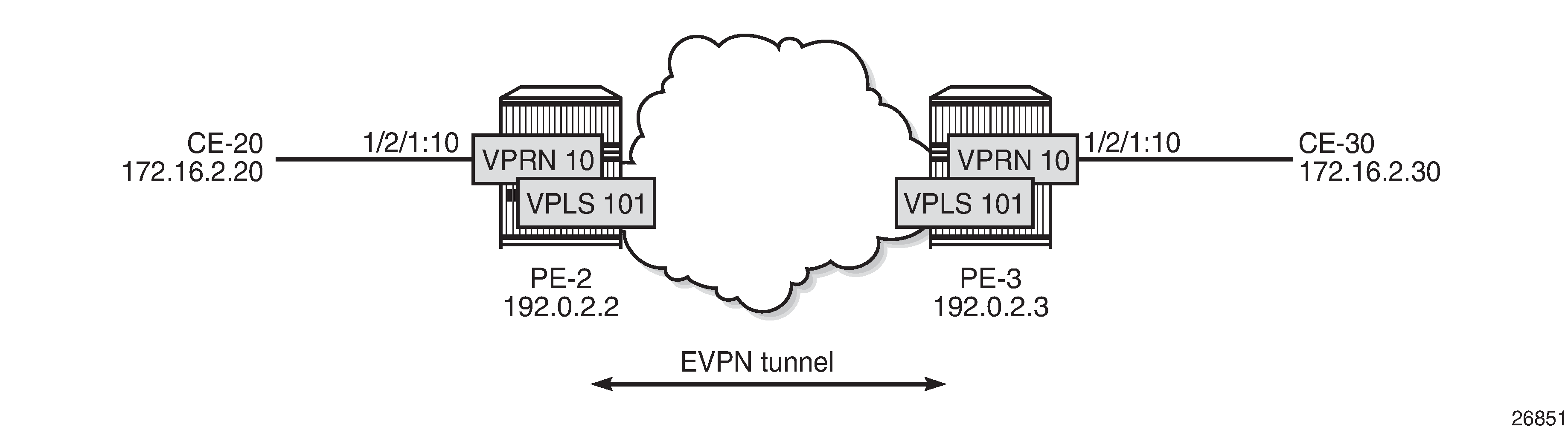
The initial configuration includes the following:
cards, MDAs, ports
router interface between PE-2 and PE-3
IS-IS (or OSPF)
LDP enabled on the router interface between PE-2 and PE-3
BGP is configured for address family EVPN on PE-2 and PE-3. The BGP configuration on PE-2 is as follows. The BGP configuration on PE-3 is similar.
# on PE-2:
configure
    router
        autonomous-system 64500
        bgp
            family evpn
            vpn-apply-import
            vpn-apply-export
            enable-peer-tracking
            rapid-withdrawal
            rapid-update evpn
            group "internal"
                peer-as 64500
                neighbor 192.0.2.3
                exit
            exit
        exit
The CEs are connected to SAP 1/2/1:10 in VPRN 10. r-VPLS 101 is bound to VPRN 10 and VPRN 10 has a dedicated interface ‟int-evi-101” for the EVPN tunnel. In general, if only one route target (RT) is used for import and export in the EVPN-VPLS, it is best to add the EVI and have the route distinguisher (RD) and RT auto-derived from the EVI; this simplifies the configuration and reduces the chance of errors. The service configuration on PE-2 is as follows:
# on PE-2:
configure
    service
        vprn 10 name "VPRN 10" customer 1 create
            route-distinguisher 192.0.2.2:10
            vrf-target target:64500:10
            interface "int-PE-2-CE-20" create
                address 172.16.2.1/24
                sap 1/2/1:10 create
                exit
            exit
            interface "int-evi-101" create
                vpls "evi-101"
  evpn-tunnel
                exit
            exit
            no shutdown
        exit
        vpls 101 name "evi-101" customer 1 create
            allow-ip-int-bind
            exit
            bgp              // RD and RT are not manually configured in BGP context
            exit
            bgp-evpn
                ip-route-advertisement
                evi 101      // RD and RT will be auto-derived from the EVI
                mpls bgp 1
                    auto-bind-tunnel
                        resolution any
                    exit
                    no shutdown
                exit
            exit
            no shutdown
        exit
In the preceding configuration:
the allow-ip-int-binding command is required so that r-VPLS 101 can be bound to VPRN 10
the service name is required and the configured name ‟evi-101” must match the name in the VPRN 10 VPLS interface. The service name is configured at service creation time.
the VPRN 10 VPLS interface is configured with the keyword evpn-tunnel. This configuration has the advantage of not having to allocate IP addresses to the r-VPLS interfaces; however, it cannot be used when the r-VPLS interface has local SAPs.
The configuration is similar on PE-3. The RD must be different on PE-2 and PE-3; this is automatically the case when the RD is auto-derived from the configured EVI, as in the example. The RD on PE-2 is 192.0.2.2:101; on PE-3, the RD is 192.0.2.3:101.
PE-3 receives the following BGP-EVPN IP prefix route for prefix 172.16.2.0/24 from PE-2:
34 2019/09/27 12:21:38.100 UTC MINOR: DEBUG #2001 Base Peer 1: 192.0.2.2
"Peer 1: 192.0.2.2: UPDATE
Peer 1: 192.0.2.2 - Received BGP UPDATE:
    Withdrawn Length = 0
    Total Path Attr Length = 97
    Flag: 0x90 Type: 14 Len: 45 Multiprotocol Reachable NLRI:
        Address Family EVPN
        NextHop len 4 NextHop 192.0.2.2
        Type: EVPN-IP-Prefix Len: 34 RD: 192.0.2.2:101, tag: 0,
ip_prefix: 172.16.2.0/24 gw_ip 0.0.0.0 Label: 8388464
    Flag: 0x40 Type: 1 Len: 1 Origin: 0
    Flag: 0x40 Type: 2 Len: 0 AS Path:
    Flag: 0x80 Type: 4 Len: 4 MED: 0
    Flag: 0x40 Type: 5 Len: 4 Local Preference: 100
    Flag: 0xc0 Type: 16 Len: 24 Extended Community:
        target:64500:101
        mac-nh:04:0b:ff:ff:ff:a2
 bgp-tunnel-encap:MPLS
"
GW IP 0.0.0.0 is an indication that an EVPN tunnel is in use. With EVPN tunnels, no IRB IP address needs to be configured in the VPRN. EVPN tunnels make provisioning easier to automate and save IP addresses from the tenant IP space.
The BGP tunnel encapsulation is MPLS, but the MPLS label in the debug message is not the same as in the service, because the router strips the extra four lowest bits to get the 20-bit MPLS label. In the debug message, the label is 8388464. This is because the debug message is shown before the router can parse the label field and see if it corresponds to an MPLS label (20 bits). The MPLS label is calculated by dividing the label value by 24 (16), as follows: 8388464/16 = 524279.
The MAC next-hop extended community 04:0b:ff:ff:ff:a2 is the MAC address of the interface ‟int-evi-101” in VPRN 10 on PE-2, as follows:
*A:PE-2# show service id 10 interface "int-evi-101" detail | match MAC
MACSec           : N/A
MAC Address      : 04:0b:ff:ff:ff:a2    Mac Accounting    : Disabled
The routing table for VPRN 10 on PE-3 contains the route for prefix 172.16.2.0/24 as the BGP-EVPN route with next-hop ‟int-evi-101” and interface name ‟ET-04:0b:ff:ff:ff:a2” (ET stands for EVPN Tunnel), as follows:
*A:PE-3# show router 10 route-table

===============================================================================
Route Table (Service: 10)
===============================================================================
Dest Prefix[Flags]                            Type    Proto     Age        Pref
      Next Hop[Interface Name]                                    Metric
-------------------------------------------------------------------------------
172.16.2.0/24                                 Remote  BGP EVPN  00h06m45s  169
 int-evi-101 (ET-04:0b:ff:ff:ff:a2)                           0
172.16.3.0/24                                 Local   Local     00h06m48s  0
       int-PE-3-CE-30                                               0
-------------------------------------------------------------------------------
No. of Routes: 2
Flags: n = Number of times nexthop is repeated
       B = BGP backup route available
       L = LFA nexthop available
       S = Sticky ECMP requested
===============================================================================
The forwarding database (FDB) for VPLS 101 on PE-3 shows an entry for MAC address 04:0b:ff:ff:ff:a2 that is learned via EVPN. The MAC address is static (S) and protected (P). The MPLS label is 524279.
*A:PE-3# show service id 101 fdb detail

===============================================================================
Forwarding Database, Service 101
===============================================================================
ServId     MAC               Source-Identifier       Type     Last Change
            Transport:Tnl-Id                         Age
-------------------------------------------------------------------------------
101        04:0b:ff:ff:ff:a2 eMpls:                  EvpnS:P  09/27/19 12:55:59
                             192.0.2.2:524279
           ldp:65538
101        04:0d:ff:ff:ff:a2 cpm                     Intf     09/27/19 12:55:57
-------------------------------------------------------------------------------
No. of MAC Entries: 2
-------------------------------------------------------------------------------
Legend:  L=Learned O=Oam P=Protected-MAC C=Conditional S=Static Lf=Leaf
===============================================================================
When the CEs have IPv6 addresses, the VPRN configuration is similar on the PEs, but the ipv6 context must be enabled on the EVPN tunnel interface so that the router can advertise and process BGP-EVPN type 5 routes with IPv6 prefixes. The configuration of VPLS is identical for IPv4 and IPv6.
# on PE-2:
configure
    service
        vprn 16 name "VPRN 16" customer 1 create
            route-distinguisher 192.0.2.2:16
            vrf-target target:64500:16
            interface "int-PE-2-CE-26" create
                ipv6
                    address 2001:db8:16::2:1/120
                exit
                sap 1/2/1:16 create
                exit
            exit
            interface "int-evi-106" create
                ipv6
                exit
                vpls "evi-106"
                    evpn-tunnel
                exit
            exit
            no shutdown
        exit
        vpls 106 name "evi-106" customer 1 create
            allow-ip-int-bind
            exit
            bgp
            exit
            bgp-evpn
                ip-route-advertisement
                evi 106
                mpls bgp 1
                    auto-bind-tunnel
                        resolution any
                    exit
                    no shutdown
                exit
            exit
            no shutdown
        exit
When advertising IPv6 prefixes, the GW IP field for route type 5 is always populated with the IPv6 address of the r-VPLS interface. In this example, because no specific IPv6 global address is configured, the GW IP will be populated with the auto-created link local address. The following BGP update is received by PE-3 for IPv6 prefix 2001:db8:16::2:0/120:
# on PE-3:
36 2019/09/27 12:21:38.123 UTC MINOR: DEBUG #2001 Base Peer 1: 192.0.2.2
"Peer 1: 192.0.2.2: UPDATE
Peer 1: 192.0.2.2 - Received BGP UPDATE:
    Withdrawn Length = 0
    Total Path Attr Length = 113
    Flag: 0x90 Type: 14 Len: 69 Multiprotocol Reachable NLRI:
        Address Family EVPN
        NextHop len 4 NextHop 192.0.2.2
        Type: EVPN-IP-Prefix Len: 58 RD: 192.0.2.2:106, tag: 0,
ip_prefix: 2001:db8:16::2:0/120 gw_ip fe80::60b:1ff:fe02:1 Label: 8388448
    Flag: 0x40 Type: 1 Len: 1 Origin: 0
    Flag: 0x40 Type: 2 Len: 0 AS Path:
    Flag: 0x80 Type: 4 Len: 4 MED: 0
    Flag: 0x40 Type: 5 Len: 4 Local Preference: 100
    Flag: 0xc0 Type: 16 Len: 16 Extended Community:
        target:64500:106
        bgp-tunnel-encap:MPLS
"
The IPv6 route table on PE-3 is as follows:
*A:PE-3# show router 16 route-table ipv6

===============================================================================
IPv6 Route Table (Service: 16)
===============================================================================
Dest Prefix[Flags]                            Type    Proto     Age        Pref
      Next Hop[Interface Name]                                    Metric
-------------------------------------------------------------------------------
2001:db8:16::2:0/120                          Remote  BGP EVPN  00h17m24s  169
       fe80::60b:1ff:fe02:1-"int-evi-106"                          0
2001:db8:16::3:0/120                          Local   Local     00h17m26s  0
       int-PE-3-CE-36                                               0
-------------------------------------------------------------------------------
No. of Routes: 2
EVPN-MPLS r-VPLS With All-Active Multihoming
EVPN-MPLS r-VPLS With All-Active Multihoming ES shows an example of the topology with all-active multihoming Ethernet segment (ES) ‟ESI-23”.
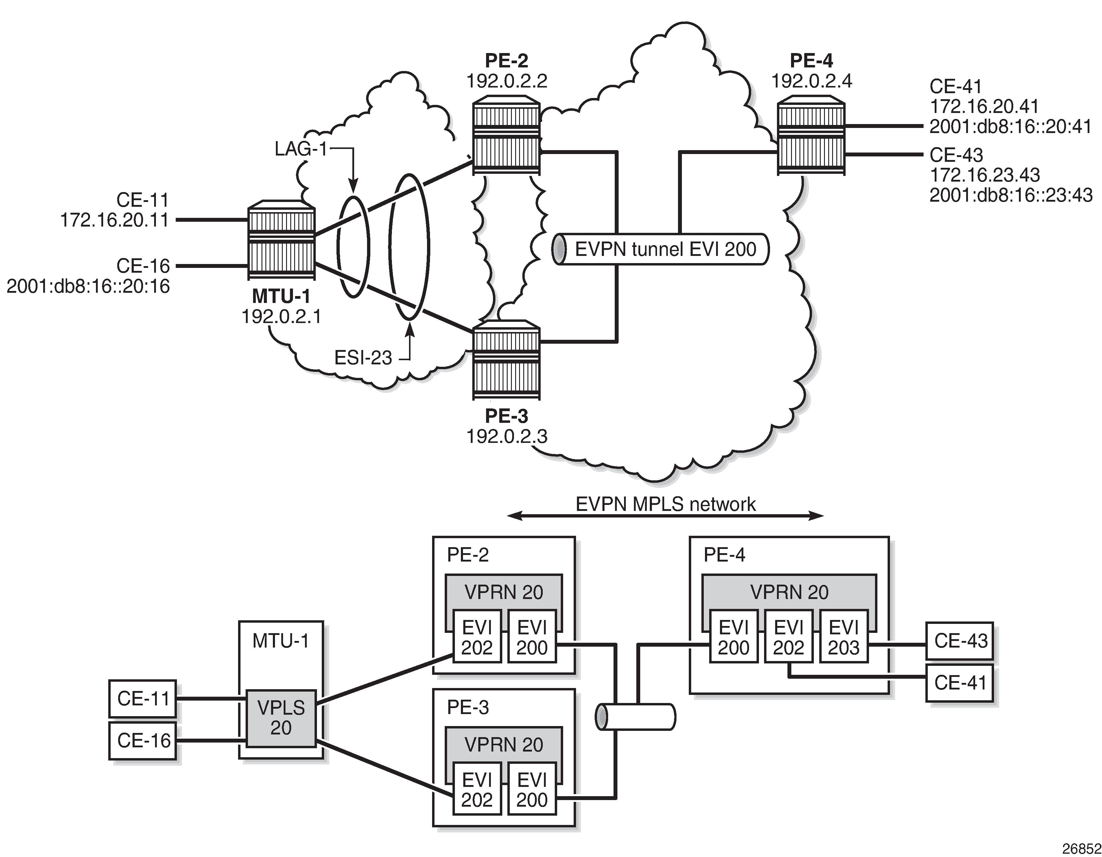
BGP is configured between PE-2, PE-3, and PE-4 for address family EVPN. The configuration on PE-2 is as follows:
# on PE-2:
configure
    router
        autonomous-system 64500
        bgp
            family evpn
            vpn-apply-import
            vpn-apply-export
            enable-peer-tracking
            rapid-withdrawal
            rapid-update evpn
            group "internal"
                peer-as 64500
                neighbor 192.0.2.3
                exit
                neighbor 192.0.2.4
                exit
            exit
        exit
All-active multihoming Ethernet segment ‟ESI-23” is configured on PE-2 and PE-3 as follows:
configure
    service
        system
            bgp-evpn
                ethernet-segment "ESI-23" create
                    esi 01:00:00:00:00:23:00:00:00:01
                    es-activation-timer 3
                    service-carving
                        mode auto
                    exit
                    multi-homing all-active
 lag 1
                    no shutdown
                exit
The following services are configured on the PEs:
VPRN 20 has interfaces bound to VPLS 200 and VPLS 202. On PE-4, VPRN 20 also has an interface bound to VPLS 203.
VPLS 200 is configured as an EVPN tunnel that connects the PEs.
VPLS 202 and VPLS 203 have attachment circuits to CEs.
The services are configured on PE-2 as follows. The configuration on PE-3 and PE-4 is similar.
# on PE-2:
configure
    service
        vprn 20 name "VPRN 20" customer 1 create
            route-distinguisher 192.0.2.2:20
            vrf-target target:64500:20
            interface "int-evi-202" create
                address 172.16.20.2/24
                mac 00:ca:fe:00:02:02
                vrrp 1 passive
 backup 172.16.20.254
                    ping-reply
                    traceroute-reply
                exit
                ipv6
                    address 2001:db8:16::20:2/120
 link-local-address fe80::16:20:2
 vrrp 1 passive
   backup fe80::16:20:fe
                        ping-reply
                        traceroute-reply
                    exit
                exit
                vpls "evi-202"
                exit
            exit
            interface "int-evi-200" create
                ipv6
                exit
                vpls "evi-200"
                    evpn-tunnel
                exit
            exit
            router-advertisement
 interface "int-evi-202"
  use-virtual-mac
  no shutdown
                exit
            exit
            no shutdown
        exit
        vpls 200 name "evi-200" customer 1 create
            allow-ip-int-bind
            exit
            bgp
            exit
            bgp-evpn
                ip-route-advertisement
                evi 200
                mpls bgp 1
                    auto-bind-tunnel
                        resolution any
                    exit
                    no shutdown
                exit
            exit
            no shutdown
        exit
        vpls 202 name "evi-202" customer 1 create
            allow-ip-int-bind
            exit
            bgp
            exit
            bgp-evpn
                evi 202
                mpls bgp 1
                    auto-bind-tunnel
                        resolution any
                    exit
                    no shutdown
                exit
            exit
            sap lag-1:20 create
            exit
            no shutdown
        exit
The IPv6 VRRP backup address is in the same subnet as the link local address of the interface ‟int-evi-202”. The IPv6 address can be set as preferred. Also for IPv6, router advertisement must be enabled and configured to use the virtual MAC address.
Passive VRRP
EVI 202 is configured as an r-VPLS interface with passive VRRP. A passive VRRP VRID instance suppresses the transmission and reception of keepalive messages. All PEs configured with passive VRRP become VRRP masters and take ownership of the virtual IP and MAC addresses.
Each individual r-VPLS interface has a different MAC/IP address on each PE. The MAC/IP addresses for ‟int-evi-202” on PE-2 are MAC 00:ca:fe:00:02:02 and IP 172.16.20.2/24 for IPv4 and the same MAC address with IPv6 2001:db8:16::20:2 and fe80::16:20:2. However, the r-VPLS interfaces on all PEs share the same VRID 1 and backup IP address 172.16.20.254, so the same vMAC/vIP 00:00:5e:00:01:01/172.16.20.254 and vMAC/vIP 00:00:5e:00:02:01/ fe80::16:20:fe are advertised by all PEs. PE-2 advertises the following EVPN MAC routes:
82 2019/09/27 12:20:38.600 UTC MINOR: DEBUG #2001 Base Peer 1: 192.0.2.3
"Peer 1: 192.0.2.3: UPDATE
Peer 1: 192.0.2.3 - Send BGP UPDATE:
    Withdrawn Length = 0
    Total Path Attr Length = 292
    Flag: 0x90 Type: 14 Len: 240 Multiprotocol Reachable NLRI:
        Address Family EVPN
        NextHop len 4 NextHop 192.0.2.2
        Type: EVPN-MAC Len: 49 RD: 192.0.2.2:202 ESI: ESI-0, tag: 0, mac len: 48
mac: 00:00:5e:00:02:01, IP len: 16, IP: fe80::16:20:fe, label1: 8388384
Type: EVPN-MAC Len: 37 RD: 192.0.2.2:202 ESI: ESI-0, tag: 0, mac len: 48
mac: 00:00:5e:00:01:01, IP len: 4, IP: 172.16.20.254, label1: 8388384
        Type: EVPN-MAC Len: 49 RD: 192.0.2.2:202 ESI: ESI-0, tag: 0, mac len: 48
          mac: 00:ca:fe:00:02:02, IP len: 16, IP: fe80::16:20:2, label1: 8388384
        Type: EVPN-MAC Len: 49 RD: 192.0.2.2:202 ESI: ESI-0, tag: 0, mac len: 48
          mac: 00:ca:fe:00:02:02, IP len: 16, IP: 2001:db8:16::20:2, label1: 8388384
        Type: EVPN-MAC Len: 37 RD: 192.0.2.2:202 ESI: ESI-0, tag: 0, mac len: 48
          mac: 00:ca:fe:00:02:02, IP len: 4, IP: 172.16.20.2, label1: 8388384
    Flag: 0x40 Type: 1 Len: 1 Origin: 0
    Flag: 0x40 Type: 2 Len: 0 AS Path:
    Flag: 0x80 Type: 4 Len: 4 MED: 0
    Flag: 0x40 Type: 5 Len: 4 Local Preference: 100
    Flag: 0xc0 Type: 16 Len: 24 Extended Community:
        target:64500:202
        bgp-tunnel-encap:MPLS
        mac-mobility:Seq:0/Static
"
The three PEs advertise the same (anycast) vMAC/vIP in EVI 202 as protected, but each PE keeps its own MAC entry in the FDB. The following FDB output shows that the source identifier for vMAC 00:00:5e:00:01:01 and vMAC 00:00:5e:00:02:01 is the CPM. These two vMAC entries with source identifier CPM are seen on all PEs.
*A:PE-2# show service id 202 fdb detail

===============================================================================
Forwarding Database, Service 202
===============================================================================
ServId     MAC               Source-Identifier       Type     Last Change
            Transport:Tnl-Id                         Age
-------------------------------------------------------------------------------
202        00:00:01:00:00:11 sap:lag-1:20            L/90     09/27/19 12:00:35
202        00:00:01:00:00:16 sap:lag-1:20            L/90     09/27/19 12:00:36
202        00:00:04:00:00:41 eMpls:                  Evpn     09/27/19 11:57:24
                             192.0.2.4:524279
           ldp:65539
202        00:00:5e:00:01:01 cpm                     Intf     09/27/19 12:20:19
202        00:00:5e:00:02:01 cpm                     Intf     09/27/19 12:20:19
202        00:ca:fe:00:02:02 cpm                     Intf     09/27/19 11:56:56
202        00:ca:fe:00:02:03 eMpls:                  EvpnS:P  09/27/19 11:57:12
                             192.0.2.3:524274
           ldp:65537
202        00:ca:fe:00:02:04 eMpls:                  EvpnS:P  09/27/19 11:57:23
                             192.0.2.4:524279
           ldp:65539
-------------------------------------------------------------------------------
No. of MAC Entries: 8
-------------------------------------------------------------------------------
Legend:  L=Learned O=Oam P=Protected-MAC C=Conditional S=Static Lf=Leaf
===============================================================================
The interface MAC 00:ca:fe:00:02:02 is local, so it also has the CPM as source identifier. MAC 00:ca:fe:00:02:03 is the r-VPLS interface MAC for PE-3 and it is learned via EVPN-MPLS (eMpls) as static (S) and protected (P). MAC address 00:ca:fe:00:02:04 on PE-4 is also static and protected.
PE-4 sends the following IP prefix route (BGP-EVPN route type 5) for prefix 172.16.23.0/24 to the other PEs:
35 2019/09/27 12:20:38.600 UTC MINOR: DEBUG #2001 Base Peer 1: 192.0.2.2
"Peer 1: 192.0.2.2: UPDATE
Peer 1: 192.0.2.2 - Send BGP UPDATE:
    Withdrawn Length = 0
    Total Path Attr Length = 97
    Flag: 0x90 Type: 14 Len: 45 Multiprotocol Reachable NLRI:
        Address Family EVPN
        NextHop len 4 NextHop 192.0.2.4
        Type: EVPN-IP-Prefix Len: 34 RD: 192.0.2.4:200, tag: 0,
                             ip_prefix: 172.16.23.0/24 gw_ip 0.0.0.0 Label: 8388384
    Flag: 0x40 Type: 1 Len: 1 Origin: 0
    Flag: 0x40 Type: 2 Len: 0 AS Path:
    Flag: 0x80 Type: 4 Len: 4 MED: 0
    Flag: 0x40 Type: 5 Len: 4 Local Preference: 100
    Flag: 0xc0 Type: 16 Len: 24 Extended Community:
        target:64500:200
        mac-nh:04:0f:ff:00:00:05
        bgp-tunnel-encap:MPLS
"
The IP prefixes are advertised with the next hop equal to the EVPN-tunnel GW MAC ‟int-evi-200”, as follows:
*A:PE-4# show router 20 interface "int-evi-200" detail | match MAC
MACSec           : N/A
MAC Address      : 04:0f:ff:00:00:05    Mac Accounting    : Disabled
The routing table for VPRN 20 on PE-2 contains IP prefix 172.16.23.0/24 with next hop 04:0f:ff:00:00:05, as follows:
*A:PE-2# show router 20 route-table

===============================================================================
Route Table (Service: 20)
===============================================================================
Dest Prefix[Flags]                            Type    Proto     Age        Pref
      Next Hop[Interface Name]                                    Metric
-------------------------------------------------------------------------------
172.16.20.0/24                                Local   Local     00h01m07s  0
       int-evi-202                                                  0
172.16.23.0/24                                Remote  BGP EVPN  00h00m48s  169
int-evi-200 (ET-04:0f:ff:00:00:05)                           0
-------------------------------------------------------------------------------
No. of Routes: 2
The following IPv6 routing table for VPRN 20 on PE-2 contains prefix 2001:db8:16::23:0/120, which has also been advertised by PE-4. The next hop is again ‟int-evi-200”, only this time the link local IPv6 address is displayed (GW IP) instead of the MAC address. The next hop is the GW IP value for route type 5, as long as it is a non-zero value. When the GW IP address is 0, route type 5 is expected to contain a mac-nh extended community. The MAC encoded in the extended community is used as the next hop in that case.
*A:PE-2# show router 20 route-table ipv6

===============================================================================
IPv6 Route Table (Service: 20)
===============================================================================
Dest Prefix[Flags]                            Type    Proto     Age        Pref
      Next Hop[Interface Name]                                    Metric
-------------------------------------------------------------------------------
2001:db8:16::20:0/120                         Local   Local     00h01m06s  0
       int-evi-202                                                  0
2001:db8:16::23:0/120                         Remote  BGP EVPN  00h00m47s  169
 fe80::a3:a899:473e:c489 -"int-evi-200"                        0
-------------------------------------------------------------------------------
No. of Routes: 2
The EVPN tunnel service VPLS 200 has all the MAC addresses of the EVPN interfaces within VPRN 20 as static (S) and protected (P), as follows:
*A:PE-2# show service id "evi-200" fdb detail

===============================================================================
Forwarding Database, Service 200
===============================================================================
ServId     MAC               Source-Identifier       Type     Last Change
            Transport:Tnl-Id                         Age
-------------------------------------------------------------------------------
200        04:0b:ff:00:00:05 cpm                     Intf     09/27/19 12:20:31
200        04:0d:ff:00:00:05 eMpls:                  EvpnS:P  09/27/19 12:20:39
                             192.0.2.3:524275
           ldp:65537
200        04:0f:ff:00:00:05 eMpls:                  EvpnS:P  09/27/19 12:20:51
                             192.0.2.4:524280
           ldp:65539
-------------------------------------------------------------------------------
No. of MAC Entries: 3
-------------------------------------------------------------------------------
Legend:  L=Learned O=Oam P=Protected-MAC C=Conditional S=Static Lf=Leaf
===============================================================================
The VRRP instance in each PE is master, as follows:
*A:PE-2# show router 20 vrrp instance

===============================================================================
VRRP Instances
===============================================================================
Interface Name                   VR Id Own Adm  State       Base Pri   Msg Int
                                 IP        Opr  Pol Id      InUse Pri  Inh Int
-------------------------------------------------------------------------------
int-evi-202                      1     No  Up   Master       100       1
                                 IPv4      Up   n/a         100        No
  Backup Addr: 172.16.20.254
int-evi-202                      1     No  Up   Master       100       1
                                 IPv6      Up   n/a         100        Yes
  Backup Addr: fe80::16:20:fe
-------------------------------------------------------------------------------
Instances : 2
===============================================================================
*A:PE-3# show router 20 vrrp instance

===============================================================================
VRRP Instances
===============================================================================
Interface Name                   VR Id Own Adm  State       Base Pri   Msg Int
                                 IP        Opr  Pol Id      InUse Pri  Inh Int
-------------------------------------------------------------------------------
int-evi-202                      1     No  Up   Master       100       1
                                 IPv4      Up   n/a         100        No
  Backup Addr: 172.16.20.254
int-evi-202                      1     No  Up   Master       100       1
                                 IPv6      Up   n/a         100        Yes
  Backup Addr: fe80::16:20:fe
-------------------------------------------------------------------------------
Instances : 2
===============================================================================
*A:PE-4# show router 20 vrrp instance

===============================================================================
VRRP Instances
===============================================================================
Interface Name                   VR Id Own Adm  State       Base Pri   Msg Int
                                 IP        Opr  Pol Id      InUse Pri  Inh Int
-------------------------------------------------------------------------------
int-evi-202                      1     No  Up   Master       100       1
                                 IPv4      Up   n/a         100        No
  Backup Addr: 172.16.20.254
int-evi-203                      2     No  Up   Master       100       1
                                 IPv4      Up   n/a         100        No
  Backup Addr: 172.16.23.254
int-evi-202                      1     No  Up   Master       100       1
                                 IPv6      Up   n/a         100        Yes
  Backup Addr: fe80::16:20:fe
int-evi-203                      2     No  Up   Master       100       1
                                 IPv6      Up   n/a         100        Yes
  Backup Addr: fe80::16:23:fe
-------------------------------------------------------------------------------
Instances : 4
===============================================================================
Operation
On PE-4, VPRN 20 has one interface bound to VPLS 202 and another interface bound to VPLS 203. CE-41 is attached to VPLS 202 and CE-43 is attached to VPLS 203. When ping messages are sent from CE-41 to CE-43, or vice versa, the messages go via VPRN 20, which has routes to both CEs, as follows:
*A:PE-4# show router 20 route-table

===============================================================================
Route Table (Service: 20)
===============================================================================
Dest Prefix[Flags]                            Type    Proto     Age        Pref
      Next Hop[Interface Name]                                    Metric
-------------------------------------------------------------------------------
172.16.20.0/24                                Local   Local     04h25m52s  0
       int-evi-202                                                  0
172.16.23.0/24                                Local   Local     04h25m51s  0
       int-evi-203                                                  0
-------------------------------------------------------------------------------
No. of Routes: 2
*A:PE-4# show router 20 route-table ipv6

===============================================================================
IPv6 Route Table (Service: 20)
===============================================================================
Dest Prefix[Flags]                            Type    Proto     Age        Pref
      Next Hop[Interface Name]                                    Metric
-------------------------------------------------------------------------------
2001:db8:16::20:0/120                         Local   Local     00h00m50s  0
       int-evi-202                                                  0
2001:db8:16::23:0/120                         Local   Local     00h00m50s  0
       int-evi-203                                                  0
-------------------------------------------------------------------------------
No. of Routes: 2
When traffic is sent between CE-11 and CE-41, which are both associated with VPLS 202, the forwarding is done by VPLS and not via the VPRN. The FDB for VPLS 202 on PE-2 is as follows:
*A:PE-2# show service id 202 fdb detail

===============================================================================
Forwarding Database, Service 202
===============================================================================
ServId     MAC               Source-Identifier       Type     Last Change
            Transport:Tnl-Id                         Age
-------------------------------------------------------------------------------
202        00:00:01:00:00:11 sap:lag-1:20            L/90     09/27/19 12:20:43
202        00:00:01:00:00:16 sap:lag-1:20            L/90     09/27/19 12:20:49
202        00:00:04:00:00:41 eMpls:                  Evpn     09/27/19 12:20:38
192.0.2.4:524275
           ldp:65539
202        00:00:5e:00:01:01 cpm                     Intf     09/27/19 12:20:19
202        00:00:5e:00:02:01 cpm                     Intf     09/27/19 12:20:19
202        00:ca:fe:00:02:02 cpm                     Intf     09/27/19 12:20:18
202        00:ca:fe:00:02:03 eMpls:                  EvpnS:P  09/27/19 12:20:26
                             192.0.2.3:524274
           ldp:65537
202        00:ca:fe:00:02:04 eMpls:                  EvpnS:P  09/27/19 12:20:37
                             192.0.2.4:524275
           ldp:65539
-------------------------------------------------------------------------------
No. of MAC Entries: 8
-------------------------------------------------------------------------------
Legend:  L=Learned O=Oam P=Protected-MAC C=Conditional S=Static Lf=Leaf
===============================================================================
MAC 00:00:01:00:00:11 corresponds to CE-11 and is learned on SAP lag-1:20 on PE-2 and advertised via an EVPN MAC route to the BGP peers. MAC 00:00:04:00:00:41 corresponds to CE-41 and was advertised via an EVPN MAC route from PE-4, where the MAC was learned on SAP 1/2/1:41 of VPLS 202, as shown in the following FDB:
*A:PE-4# show service id 202 fdb detail

===============================================================================
Forwarding Database, Service 202
===============================================================================
ServId     MAC               Source-Identifier       Type     Last Change
            Transport:Tnl-Id                         Age
-------------------------------------------------------------------------------
202        00:00:01:00:00:11 eES:                    Evpn     09/27/19 12:20:04
                             01:00:00:00:00:23:00:00:00:01
202        00:00:01:00:00:16 eES:                    Evpn     09/27/19 12:20:10
                             01:00:00:00:00:23:00:00:00:01
202        00:00:04:00:00:41 sap:1/2/1:41            L/0      09/27/19 12:19:59
202        00:00:5e:00:01:01 cpm                     Intf     09/27/19 12:19:58
202        00:00:5e:00:02:01 cpm                     Intf     09/27/19 12:19:58
202        00:ca:fe:00:02:02 eMpls:                  EvpnS:P  09/27/19 12:19:59
                             192.0.2.2:524274
           ldp:65537
202        00:ca:fe:00:02:03 eMpls:                  EvpnS:P  09/27/19 12:19:59
                             192.0.2.3:524274
           ldp:65539
202        00:ca:fe:00:02:04 cpm                     Intf     09/27/19 12:19:58
-------------------------------------------------------------------------------
No. of MAC Entries: 8
-------------------------------------------------------------------------------
Legend:  L=Learned O=Oam P=Protected-MAC C=Conditional S=Static Lf=Leaf
===============================================================================
The MAC address of CE-43 is not present in the FDB of VPLS 202. The FDB of VPLS 203 shows the MAC address of CE-43, but not of CE-41. Traffic between these two VPLS services goes via the VPRN and cannot use Layer 2 forwarding.
*A:PE-4# show service id 203 fdb detail

===============================================================================
Forwarding Database, Service 203
===============================================================================
ServId     MAC               Source-Identifier       Type     Last Change
            Transport:Tnl-Id                         Age
-------------------------------------------------------------------------------
203        00:00:04:00:00:43 sap:1/2/1:43            L/0      09/27/19 12:20:32
203        00:00:5e:00:01:02 cpm                     Intf     09/27/19 12:20:16
203        00:00:5e:00:02:02 cpm                     Intf     09/27/19 12:20:16
203        00:ca:fe:00:23:04 cpm                     Intf     09/27/19 12:20:16
-------------------------------------------------------------------------------
No. of MAC Entries: 4
-------------------------------------------------------------------------------
Legend:  L=Learned O=Oam P=Protected-MAC C=Conditional S=Static Lf=Leaf
===============================================================================
EVPN-MPLS r-VPLS With Single-Active Multihoming
EVPN-MPLS r-VPLS With Single-Active Multihoming shows an example of topology with single-active multihoming ES ‟ESI-23”. The difference between this figure and EVPN-MPLS r-VPLS With All-Active Multihoming ES is that in EVPN-MPLS r-VPLS With Single-Active Multihoming the ES is single-active and SDPs are used instead of a LAG.
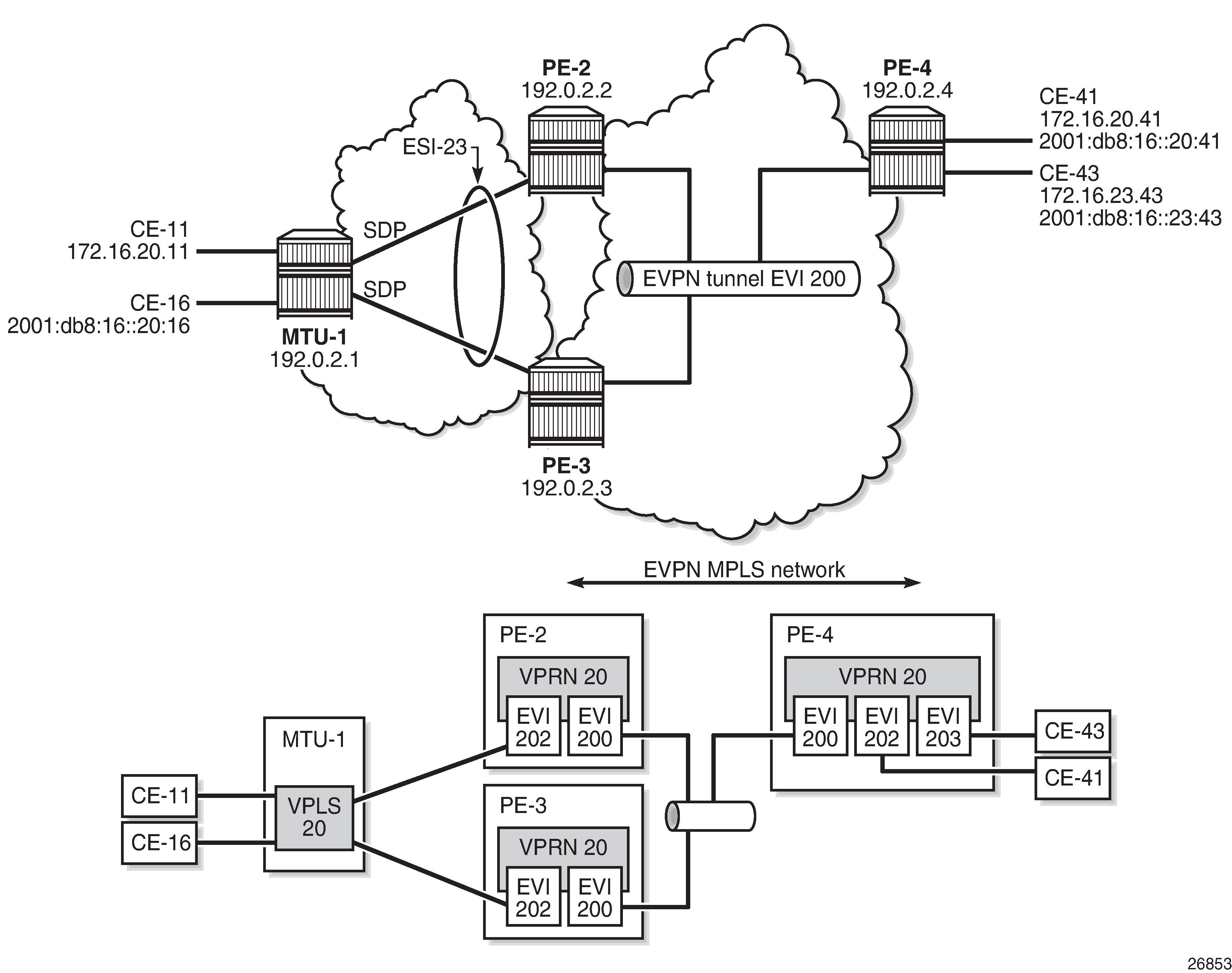
The configuration is modified as follows:
LAG 1 is removed from MTU-1, PE-2, and PE-3
network interfaces are configured between MTU-1 and PE-2/PE-3 with IS-IS and LDP enabled
SDPs are configured
ES ‟ESI-23” is redefined as single-active multihoming. The SDP is associated with this ES.
VPLS 202 on PE-2 and PE-3 no longer has a SAP, but has a spoke SDP instead
no changes are required on VPRN 20 or VPLS 200
The service configuration on PE-2 is as follows. The configuration on PE-3 is similar. No changes are required on PE-4.
*A:PE-2# configure service
*A:PE-2>config>service# info
----------------------------------------------
        system
            bgp-evpn
                ethernet-segment "ESI-23"  create
                    esi 01:00:00:00:00:23:00:00:00:01
                    es-activation-timer 3
                    service-carving
                        mode auto
                    exit
                    multi-homing single-active
sdp 21
                    no shutdown
                exit
            exit
        exit
---snip---
        sdp 21 mpls create
 far-end 192.0.2.1
ldp
            keep-alive
                shutdown
            exit
            no shutdown
        exit
---snip---
        vprn 20 name "VPRN 20" customer 1 create
            route-distinguisher 192.0.2.2:20
            vrf-target target:64500:20
            interface "int-evi-202" create
                address 172.16.20.2/24
                mac 00:ca:fe:00:02:02
                vrrp 1 passive
                    backup 172.16.20.254
                    ping-reply
                    traceroute-reply
                exit
                ipv6
                    address 2001:db8:16::20:2/120
                    link-local-address fe80::16:20:2 dad-disable
                    vrrp 1 passive
                        backup fe80::16:20:fe
                        ping-reply
                        traceroute-reply
                    exit
                exit
                vpls "evi-202"
                exit
            exit
            interface "int-evi-200" create
                ipv6
                exit
                vpls "evi-200"
                    evpn-tunnel
                exit
            exit
            router-advertisement
                interface "int-evi-202"
                    use-virtual-mac
                    no shutdown
                exit
            exit
            no shutdown
        exit
        vpls 200 name "evi-200" customer 1 create
            allow-ip-int-bind
            exit
            bgp
            exit
            bgp-evpn
                ip-route-advertisement
                evi 200
                mpls bgp 1
                    auto-bind-tunnel
                        resolution any
                    exit
                    no shutdown
                exit
            exit
            stp
                shutdown
            exit
            no shutdown
        exit
        vpls 202 name "evi-202" customer 1 create
            allow-ip-int-bind
            exit
            bgp
            exit
            bgp-evpn
                evi 202
                mpls bgp 1
                    auto-bind-tunnel
                        resolution any
                    exit
                    no shutdown
                exit
            exit
            stp
                shutdown
            exit
            spoke-sdp 21:20 create
                no shutdown
            exit
            no shutdown
        exit
PE-2 is the designated forwarder (DF) in the single-active ES, as shown in the following output:
*A:PE-2# show service id 202 ethernet-segment
No sap entries
===============================================================================
SDP Ethernet-Segment Information
===============================================================================
SDP                   Eth-Seg                          Status
-------------------------------------------------------------------------------
21:20                 ESI-23                           DF
===============================================================================
*A:PE-3# show service id 202 ethernet-segment
No sap entries
===============================================================================
SDP Ethernet-Segment Information
===============================================================================
SDP                   Eth-Seg                          Status
-------------------------------------------------------------------------------
31:20                 ESI-23                           NDF
===============================================================================
When traffic is sent between CE-11 and CE-41, the FDB on PE-2 is as follows, where MAC address 00:00:01:00:00:11 corresponds to CE-11 and is learned on spoke SDP 21:20, and MAC address 00:00:04:00:00:41 corresponds to CE-41 and his advertised by PE-4 in an EVPN-MAC route.
*A:PE-2# show service id 202 fdb detail

===============================================================================
Forwarding Database, Service 202
===============================================================================
ServId     MAC               Source-Identifier       Type     Last Change
            Transport:Tnl-Id                         Age
-------------------------------------------------------------------------------
202        00:00:01:00:00:11 sdp:21:20               L/30     09/27/19 12:24:05
202        00:00:01:00:00:16 sdp:21:20               L/30     09/27/19 12:24:10
202        00:00:04:00:00:41 eMpls:                  Evpn     09/27/19 12:20:38
                             192.0.2.4:524275
           ldp:65539
202        00:00:5e:00:01:01 cpm                     Intf     09/27/19 12:20:19
202        00:00:5e:00:02:01 cpm                     Intf     09/27/19 12:20:19
202        00:ca:fe:00:02:02 cpm                     Intf     09/27/19 12:20:18
202        00:ca:fe:00:02:03 eMpls:                  EvpnS:P  09/27/19 12:20:26
                             192.0.2.3:524274
           ldp:65537
202        00:ca:fe:00:02:04 eMpls:                  EvpnS:P  09/27/19 12:20:37
                             192.0.2.4:524275
           ldp:65539
-------------------------------------------------------------------------------
No. of MAC Entries: 8
-------------------------------------------------------------------------------
Legend:  L=Learned O=Oam P=Protected-MAC C=Conditional S=Static Lf=Leaf
===============================================================================
When the SDP between MTU-1 and DF PE-2 goes down, traffic from CE-41 to CE-11 is forwarded by PE-4 to DF PE-2. PE-2 cannot forward the packets to CE-11 directly and will forward the packets to its ES peer PE-3. PE-3 will forward to CE-11 even if the MAC SA matches its own vMAC. Virtual MACs bypass the r-VPLS interface protection, so traffic can be forwarded between the PEs without being dropped.
EVPN Command Reference
Command Hierarchies
Tools Commands (see the Tools section of the 7705 SAR OAM and Diagnostics Guide)
EVPN Configuration Commands
Epipe Commands for EVPN
config
    - service
        - epipe
            - [no] bgp
                - route-distinguisher rd
                - no route-distinguisher
                - route-target {ext-community | export ext-community | import ext-community}
                - no route-target
            - [no] bgp-evpn
                - evi value
                - no evi
                - local-ac-name ac-name
                - no local-ac-name
                    - eth-tag tag-value
                    - no eth-tag
                - mpls
                    - auto-bind-tunnel
                        - ecmp max-ecmp-routes
                        - resolution-filter
                            - [no] bgp
                            - [no] ldp
                            - [no] rsvp
                            - [no] sr-isis
                            - [no] sr-ospf
                            - [no] sr-te
                        - [no] weighted-ecmp
                    - [no] control-word
                    - ecmp max-ecmp-routes
                    - [no] entropy-label
                    - [no] force-vlan-vc-forwarding
                    - [no] shutdown
                - remote-ac-name ac-name
                - no remote-ac-name
                    - eth-tag tag-value
                    - no eth-tag
VPLS Commands for EVPN
config
    - service
        - vpls
            - [no] bgp
                - route-distinguisher rd
                - no route-distinguisher
                - route-target ext-community
                - route-target export ext-community [import ext-community]
                - route-target import ext-community
                - no route-target
                - vsi-export policy-name [policy-name...(up to 5 max)]
                - no vsi-export
                - vsi-import policy-name [policy-name...(up to 5 max)]
                - no vsi-import
            - [no] bgp-evpn
                - [no] cfm-mac-advertisement
                - evi value
                - [no] evi
                - incl-mcast-orig-ip ip-address
                - no incl-mcast-orig-ip
                - [no] ingress-repl-inc-mcast-advertisement
                - ip-route-advertisement [incl-host]
                - no ip-route-advertisement
                - [no] mac-advertisement
                - mac-duplication
                    - detect num-moves num-moves window minutes
                    - retry minutes
                    - [no] retry
                - mpls
                    - auto-bind-tunnel
                        - ecmp max-ecmp-routes
                        - resolution {disabled | any | filter}
                        - resolution-filter
                            - [no] bgp
                            - [no] ldp
                            - [no] rsvp
                            - [no] sr-isis
                            - [no] sr-ospf
                            - [no] sr-te
                        - [no] weighted-ecmp
                    - [no] control-word
                    - ecmp max-ecmp-routes
                    - [no] entropy-label
                    - [no] force-vlan-vc-forwarding
                    - [no] ingress-replication-bum-label
                    - [no] shutdown
                    - split-horizon-group name
                    - no split-horizon-group
            - static-mac
                - mac ieee-address [create] black-hole
                - mac ieee-address [create] sap sap-id monitor {fwd-status}
                - mac ieee-address [create] spoke-sdp sdp-id:vc-id monitor {fwd-status}
                - no mac ieee-address
Epipe and VPLS Services Related Commands for EVPN
config
    - service
        - epipe    (see Epipe Service Configuration Commands)
        - vpls      (see VPLS Command Reference)
VPRN Interface Commands for EVPN
config
    - service
        - vprn
            - interface
                - vpls
                    - [no] evpn-tunnel
Service System Commands for EVPN
config
    - service
        - system
            - [no] bgp-evpn
                - ad-per-es-route-target evi-rt
                - ad-per-es-route-target evi-rt-set route-distinguisher ip-address
                - ethernet-segment name [create]
                - no ethernet-segment name
                    - es-activation-timer seconds
                    - no es-activation-timer
                    - esi esi
                    - no esi
                    - lag lag-id
                    - no lag
                    - multi-homing single-active [no-esi-label]
                    - multi-homing all-active
                    - no multi-homing
                    - port port-id
                    - no port
                    - sdp sdp-id
                    - no sdp
                    - service-carving
                        - manual
                            - evi start [to to]
                            - no evi start
                            - preference [create] [non-revertive]
                            - no preference
                                - value value
                        - mode {manual | auto | off}
                    - [no] shutdown
                - route-distinguisher rd
                - no route-distinguisher
Redundancy Commands for EVPN
config
    - redundancy
        - bgp-evpn-multi-homing
                - boot-timer seconds
                - es-activation-timer seconds
Router BGP Commands for EVPN
See the 7705 SAR Routing Protocols Guide for router BGP command descriptions.
config
    - router
        - [no] bgp
            - def-recv-evpn-encap mpls
            - family [evpn]
            - group name
            - no group
                - def-recv-evpn-encap mpls
                - family [evpn]
                - neighbor ip-address
                    - def-recv-evpn-encap mpls
                    - family [evpn]
            - rapid-update [mvpn-ipv4] [evpn]
            - no rapid-update
Show Commands
show
    - service
        - evpn-mpls [tep-ip-address]
        - id service-id
            - bgp
            - bgp-evpn
            - evpn-mpls
            - evpn-mpls esi esi
            - ethernet-segment [ethernet-segment-name]
        - system
            - bgp-evpn
            - bgp-evpn ethernet-segment
            - bgp-evpn ethernet-segment name name [all]
            - bgp-evpn ethernet-segment name name evi [evi]
            - bgp-route-distinguisher [vpls] [epipe]
            - bgp-route-distinguisher svc
            - bgp-route-distinguisher ad-evi-rt-set
            - bgp-route-distinguisher system
show
    - redundancy
        - bgp-evpn-multi-homing
Command Descriptions
EVPN Configuration Commands
BGP Commands
bgp
Syntax
[no] bgp
Context
config>service>epipe
config>service>vpls
Description
This command enables the context to configure the BGP-related parameters for a BGP Epipe or VPLS.
The no version of the command removes the BGP instance.
route-distinguisher
Syntax
route-distinguisher rd
no route-distinguisher
Context
config>service>epipe>bgp
config>service>vpls>bgp
Description
This command configures the route distinguisher (RD) component that is signaled in the MP-BGP NLRI for Layer 2 VPN and EVPN families. This value is used for the BGP Epipe NLRI and BGP VPLS NLRI when this command is configured.
Alternatively, for BGP-EVPN-enabled Epipe and VPLS services, the route-distinguisher value can be auto-derived from the evi evi value (config>service>epipe>bgp-evpn>evi or config>service>vpls>bgp-evpn>evi) if this command is not configured.
Default
no route-distinguisher
Parameters
- rd
specifies the route distinguisher address
route-target
Syntax
For Epipe:
route-target {ext-community | export ext-community | import ext-community}
no route-target
For VPLS:
route-target ext-community
route-target export ext-community [import ext-community]
route-target import ext-community
no route-target
Context
config>service>epipe>bgp
config>service>vpls>bgp
Description
This command configures the route target (RT) component that is signaled in the related MP-BGP attribute that is used for the BGP Epipe, BGP VPLS, and EVPN when this command is configured in this Epipe or VPLS service.
If this command is not used, the RT is formed automatically using the Epipe or VPLS ID. The extended community can have the same two formats as the Epipe or VPLS ID, that is, a two-octet AS-specific extended community or an IPv4-specific extended community. The extended community can also have a four-octet AS-specific community format. For BGP-EVPN-enabled Epipe and VPLS services, the route target can also be auto-derived from the evi value (config>service>vpls>bgp-evpn>evi or config>service>epipe>bgp-evpn>evi) if this command is not configured.
Default
no route-target
Parameters
- export ext-community
specifies extended communities allowed to be sent to remote PE neighbors
- import ext-community
specifies extended communities allowed to be accepted from remote PE neighbors
- ext-community
specifies the extended community
vsi-export
Syntax
vsi-export policy-name [policy-name ... (up to 5 max)]
no vsi-export
Context
config>service>vpls>bgp
Description
This command specifies the name of the virtual switch instance (VSI) export policies to be used for BGP VPLS when this command is configured in this VPLS service. If multiple policy names are configured, the policies are evaluated in the order in which they are specified. The first policy that matches is applied.
The policy name list is handled by the SNMP agent as a single entity.
Default
no vsi-export
Parameters
- policy-name
specifies a VSI export policy (32 characters maximum)
vsi-import
Syntax
vsi-import policy-name [policy-name ... (up to 5 max)]
no vsi-import
Context
config>service>vpls>bgp
Description
This command specifies the name of the virtual switch instance (VSI) import policies to be used for BGP VPLS when this command is configured in this VPLS service. If multiple policy names are configured, the policies are evaluated in the order in which they are specified. The first policy that matches is applied.
The policy name list is handled by the SNMP agent as a single entity.
Default
no vsi-import
Parameters
- policy-name
specifies a VSI import policy (32 characters maximum)
BGP-EVPN Commands
bgp-evpn
Syntax
[no] bgp-evpn
Context
config>service>epipe
config>service>vpls
Description
This command enables the context to configure the BGP-EVPN parameters in the specified service.
cfm-mac-advertisement
Syntax
[no] cfm-mac-advertisement
Context
config>service>vpls>bgp-evpn
Description
This command enables the advertisement and withdrawal, as appropriate, of the IEEE MAC address associated with the MEP created on a SAP in an EVPN service.
The update occurs each time a MEP is added or deleted or an IEEE MAC address is changed for an MEP on a SAP within the service. The size of the update depends on the number of MEPs in the service affected by the modification.
Only enable this functionality for services that require a resident MAC address to properly forward unicast traffic and that do not perform Layer 2 MAC learning as part of the data plane.
Local MEP IEEE MAC addresses are not stored in the local FDB and therefore cannot be advertised through a control plane to a peer without this command.
The no version of the command disables the functionality and withdraws all previously advertised MEP IEEE MAC addresses.
Default
no cfm-mac-advertisement
evi
Syntax
evi value
[no] evi
Context
config>service>epipe>bgp-evpn
config>service>vpls>bgp-evpn
Description
This command specifies a 2-byte EVPN instance (EVI) that is unique in the system. It is used for the service-carving algorithm for multihoming and for auto-deriving route targets and route distinguishers.
If not specified, the evi value is 0 and there are no route distinguishers or route targets auto-derived from the value. If the evi value is specified and no other route distinguishers or route targets are configured in the service, the following rules apply:
the route distinguisher is derived from system-ip:evi value
the route target is derived from autonomous-system:evi value
If VSI import and VSI export policies are configured, the route target must be configured in the policies and the policy values take preference over the auto-derived route targets. The operational route target for a service is shown using the show>service>id>bgp command.
The no version of the command sets the evi value back to 0.
Default
no evi
Parameters
- value
specifies the EVPN instance
incl-mcast-orig-ip
Syntax
incl-mcast-orig-ip ip-address
no incl-mcast-orig-ip
Context
config>service>vpls>bgp-evpn
Description
This command specifies that the IP address configured with the command is encoded in the originating-ip field of EVPN Inclusive Multicast Routes with tunnel type Ingress Replication (IR) (value 6).
The configured address does not need to be reachable in the base router or have an interface in the base router. The originating IP address is used solely for BGP route-key selection.
The no version of the command withdraws the affected Inclusive Multicast Routes and readvertises the routes with the default system IP address in the originating IP field.
Default
system IP address
Parameters
- ip-address
specifies the IPv4 address value
ingress-repl-inc-mcast-advertisement
Syntax
[no] ingress-repl-inc-mcast-advertisement
Context
config>service>vpls>bgp-evpn
Description
This command enables the advertisement of the inclusive multicast Ethernet tag route with tunnel type ingress-replication in the PMSI tunnel attribute.
Default
ingress-repl-inc-mcast-advertisement
ip-route-advertisement
Syntax
ip-route-advertisement [incl-host]
no ip-route-advertisement
Context
config>service>vpls>bgp-evpn
Description
This command enables or disables the advertisement of IP prefixes in EVPN. When enabled, any active route in the r-VPLS VPRN route table will be advertised in EVPN using the VPLS BGP configuration. The interface host addresses are not advertised in EVPN unless the incl-host parameter is specified.
Default
no ip-route-advertisement
Parameters
- incl-host
specifies to advertise the interface host addresses in EVPN
local-ac-name
Syntax
local-ac-name ac-name
no local-ac-name
Context
config>service>epipe>bgp-evpn
Description
This command enables the context and specifies the attachment circuit name in which the local Ethernet tag value is configured.
Default
no local-ac-name
Parameters
- ac-name
specifies the name of the local attachment circuit
eth-tag
Syntax
eth-tag tag-value
no eth-tag
Context
config>service>epipe>bgp-evpn>local-ac-name
config>service>epipe>bgp-evpn>remote-ac-name
Description
This command configures the Ethernet tag value. When configured in the local-ac-name context, the system uses the value in the advertised AD per-EVI route sent for the attachment circuit. When configured in the remote-ac-name context, the system compares that value with the eth-tag tag-value of the imported AD per-EVI routes for the service. If there is a match, the system creates an EVPN-MPLS destination for the Epipe.
Default
n/a
Parameters
- tag-value
specifies the Ethernet tag value of the attachment circuit
mac-advertisement
Syntax
[no] mac-advertisement
Context
config>service>vpls>bgp-evpn
Description
This command enables the advertisement in BGP of the learned MAC addresses on SAPs and SDP bindings. When the mac-advertisement command is disabled, the local MAC addresses are withdrawn in BGP.
Default
mac-advertisement
mac-duplication
Syntax
mac-duplication
Context
config>service>vpls>bgp-evpn
Description
This command enables the context to configure the BGP-EVPN MAC duplication parameters.
detect
Syntax
detect num-moves num-moves window minutes
Context
config>service>vpls>bgp-evpn>mac-duplication
Description
This command modifies the default behavior of the mac-duplication command. The mac-duplication feature is always enabled by default and monitors the number of moves of a MAC address for a period of time (window).
Default
num-moves 5 window 3
Parameters
- num-moves
specifies the number of MAC moves in a VPLS service. The counter is incremented when a specified MAC is locally relearned in the FDB or flushed from the FDB due to the reception of a better remote EVPN route for that MAC.
- minutes
specifies the duration of the window
retry
Syntax
retry minutes
no retry
Context
config>service>vpls>bgp-evpn>mac-duplication
Description
This command specifies the timer after which the MAC in hold-down state is automatically flushed and the MAC duplication process starts again. This value is expected to be equal to or greater than two times that of the window minutes.
The no form of the command implies that when MAC duplication is detected, MAC updates for that MAC will be held down until the user intervenes or a network event that flushes the MAC occurs.
Default
9
Parameters
- minutes
specifies the BGP EVPN MAC duplication retry
mpls
Syntax
mpls
Context
config>service>epipe>bgp-evpn
config>service>vpls>bgp-evpn
Description
This command enables the context to configure the BGP-EVPN MPLS parameters.
auto-bind-tunnel
Syntax
auto-bind-tunnel
Context
config>service>epipe>bgp-evpn>mpls
config>service>vpls>bgp-evpn>mpls
Description
This command enables the context to configure automatic binding of a BGP-EVPN MPLS service to tunnels to MP-BGP peers.
ecmp
Syntax
ecmp max-ecmp-routes
Context
config>service>epipe>bgp-evpn>mpls>auto-bind-tunnel
config>service>vpls>bgp-evpn>mpls>auto-bind-tunnel
Description
This command enables ECMP for Layer 2 unicast traffic on Epipe or VPLS services for EVPN-MPLS destinations. The command allows the resolution of an EVPN-MPLS next hop to a group of ECMP tunnels of type RSVP-TE or SR-TE and determines the number of Traffic Engineering (TE) tunnels that the EVPN-MPLS next hop can be resolved to. For shortest path tunnels, such as LDP, SR-ISIS, and SR-OSPF, the number of tunnels in the ECMP group is determined by the config>router>ecmp command.
Default
1
Parameters
- max-ecmp-routes
specifies the number of TE tunnels that an EVPN-MPLS next hop can be resolved to
resolution
Syntax
resolution {disabled | any | filter}
Context
config>service>epipe>bgp-evpn>mpls>auto-bind-tunnel
config>service>vpls>bgp-evpn>mpls>auto-bind-tunnel
Description
This command configures the resolution mode in the automatic binding of a BGP-EVPN MPLS service to tunnels to MP-BGP peers.
The user must configure the resolution command to enable auto-bind resolution to tunnels in the tunnel table manager (TTM). The following options are available:
disabled (explicitly set): auto-binding to the tunnel is removed
any: any supported tunnel type in the EVPN context will be selected according to TTM preference
filter: when filter and one or more tunnel types are explicitly specified under the resolution-filter command, only those tunnel types are selected according to TTM preference
The user must set the resolution command to filter in order to activate the list of tunnel types configured under the resolution-filter command.
Default
disabled
Parameters
- any
enables the binding to any supported tunnel type in a BGP-EVPN MPLS context following TTM preference
- disabled
disables the automatic binding of a BGP-EVPN MPLS service to tunnels to MP-BGP peers
- filter
enables the binding to the subset of tunnel types configured under resolution-filter
resolution-filter
Syntax
resolution-filter
Context
config>service>epipe>bgp-evpn>mpls>auto-bind-tunnel
config>service>vpls>bgp-evpn>mpls>auto-bind-tunnel
Description
This command enables the context that allows the configuration of the subset of tunnel types that can be used in the resolution of BGP-EVPN routes within the automatic binding of BGP-EVPN MPLS service to tunnels to MP-BGP peers.
The user must set the resolution command to filter in order to activate the list of tunnel types configured under the resolution-filter command.
The following tunnel types are supported in a BGP-EVPN MPLS context in order of preference: RSVP, SR-TE, LDP, SR-ISIS, SR-OSPF, and BGP.
bgp
Syntax
[no] bgp
Context
config>service>epipe>bgp-evpn>mpls>auto-bind-tunnel>resolution-filter
config>service>vpls>bgp-evpn>mpls>auto-bind-tunnel>resolution-filter
Description
This command selects the BGP tunnel type.
The bgp command instructs BGP-EVPN to search for a BGP LSP to the address of the BGP next hop. If the user does not enable the BGP tunnel type, inter-area or inter-as prefixes will not be resolved.
ldp
Syntax
[no] ldp
Context
config>service>vpls>bgp-evpn>mpls>auto-bind-tunnel>resolution-filter
config>service>epipe>bgp-evpn>mpls>auto-bind-tunnel>resolution-filter
Description
This command selects the LDP tunnel type.
The ldp command instructs BGP to search for an LDP LSP with a FEC prefix corresponding to the address of the BGP next hop.
rsvp
Syntax
[no] rsvp
Context
config>service>vpls>bgp-evpn>mpls>auto-bind-tunnel>resolution-filter
config>service>epipe>bgp-evpn>mpls>auto-bind-tunnel>resolution-filter
Description
This command selects the RSVP-TE tunnel type.
The rsvp command instructs BGP to search for the best metric RSVP-TE LSP to the address of the BGP next hop. This address can correspond to the system interface or to another loopback address used by the BGP instance on the remote node. The LSP metric is provided by MPLS in the tunnel table. If there are multiple RSVP-TE LSPs with the same lowest metric, BGP selects the LSP with the lowest tunnel ID.
sr-isis
Syntax
[no] sr-isis
Context
config>service>vpls>bgp-evpn>mpls>auto-bind-tunnel>resolution-filter
config>service>epipe>bgp-evpn>mpls>auto-bind-tunnel>resolution-filter
Description
This command selects the segment routing (SR) tunnel type programed by an IS-IS instance in the TTM.
When the sr-isis or sr-ospf command is enabled, a segment routing (SR) tunnel to the BGP next hop is selected in the TTM from the lowest numbered IS-IS or OSPF instance.
sr-ospf
Syntax
[no] sr-ospf
Context
config>service>epipe>bgp-evpn>mpls>auto-bind-tunnel>resolution-filter
config>service>vpls>bgp-evpn>mpls>auto-bind-tunnel>resolution-filter
Description
This command selects the segment routing (SR) tunnel type programed by an OSPF instance in the TTM.
When the sr-isis or sr-ospf command is enabled, a segment routing (SR) tunnel to the BGP next hop is selected in the TTM from the lowest numbered IS-IS or OSPF instance.
sr-te
Syntax
[no] sr-te
Context
config>service>epipe>bgp-evpn>mpls>auto-bind-tunnel>resolution-filter
config>service>vpls>bgp-evpn>mpls>auto-bind-tunnel>resolution-filter
Description
This command selects the segment routing traffic engineered LSP programmed in the TTM.
The sr-te command instructs the code to search for the best metric SR-TE LSP to the address of the BGP next hop. The LSP metric is provided by MPLS in the tunnel table. If there are multiple SR-TE LSPs with the same lowest metric, BGP selects the LSP with the lowest tunnel ID.
weighted-ecmp
Syntax
[no] weighted-ecmp
Context
config>service>epipe>bgp-evpn>mpls>auto-bind-tunnel
config>service>vpls>bgp-evpn>mpls>auto-bind-tunnel
Description
This command enables weighted ECMP for packets using tunnels that an Epipe or VPLS automatically binds to. When weighted ECMP is enabled, packets are sprayed across LSPs in the ECMP set according to the outcome of the hash algorithm and the configured load-balancing-weight of each LSP. See the 7250 IXR MPLS Guide, ‟MPLS Commands” for more information about the load-balancing-weight command.
The no form of this command disables weighted ECMP for next-hop tunnel selection.
Default
no weighted-ecmp
control-word
Syntax
[no] control-word
Context
config>service>epipe>bgp-evpn>mpls
config>service>vpls>bgp-evpn>mpls
Description
This command enables the transmission and reception of the control word. As defined in RFC 7432, the use of the control word helps avoid frame disordering.
The control-word command is enabled or disabled for all EVPN-MPLS destinations at the same time.
Default
no control-word
ecmp
Syntax
ecmp max-ecmp-routes
Context
config>service>epipe>bgp-evpn>mpls
config>service>vpls>bgp-evpn>mpls
Description
This command controls the number of paths allowed to reach a specified MAC address when that MAC in the FDB is associated with a remote all-active multihomed Ethernet segment.
The configuration of two or more ECMP paths to a specified MAC enables the aliasing function described in RFC 7432.
Default
0
Parameters
- max-ecmp-routes
specifies the number of paths allowed to the same multihomed MAC address, assuming the MAC is located in an all-active multihomed Ethernet segment
entropy-label
Syntax
[no] entropy-label
Context
config>service>epipe>bgp-evpn>mpls
config>service>vpls>bgp-evpn>mpls
Description
This command inserts the entropy label (EL) and entropy label indicator (ELI) in packets for which at least one LSP in the stack for the far end of the tunnel used by the service has advertised entropy-label capability. If the tunnel is the rsvp type, entropy-label can also be controlled under the config>router>mpls or config>router>mpls>lsp context.
Default
no entropy-label
force-vlan-vc-forwarding
Syntax
[no] force-vlan-vc-forwarding
Context
config>service>epipe>bgp-evpn>mpls
config>service>vpls>bgp-evpn>mpls
Description
This command allows the system to preserve the VLAN ID and 802.1p bits of the service-delimiting qtag in a new tag added in the customer frame before sending it to the EVPN-MPLS destinations.
This command may be used in conjunction with the sap ingress vlan-translation command. If it is used, the configured translated VLAN ID will be the VLAN ID sent to the EVPN-MPLS destinations as opposed to the service-delimiting tag VLAN ID. If the ingress SAP or SDP binding is null-encapsulated, the output VLAN ID and P-bits will be 0.
Default
no force-vlan-vc-forwarding
ingress-replication-bum-label
Syntax
[no] ingress-replication-bum-label
Context
config>service>vpls>bgp-evpn>mpls
Description
This command allows the user to configure the system so that a separate label is sent for BMU (broadcast, multicast, and unknown unicast) traffic in a specified service. By default, the same label is used for unicast and flooded BMU packets when forwarding traffic to remote PEs.
When saving label space, this may cause transient packet duplication for all-active multihoming. By enabling ingress-replication-bum-label, the system will advertise two labels per EVPN VPLS instance, one for unicast and one for BMU traffic. The ingress PE will use the BMU label for flooded traffic to the advertising egress PE so that the egress PE can determine if the unicast traffic has been flooded by the ingress PE. Depending on the scale required in the network, the user may choose between saving label space or avoiding transient packet duplication sent to an all-active multihomed CE for certain MAC addresses.
Default
no ingress-replication-bum-label
shutdown
Syntax
[no] shutdown
Context
config>service>epipe>bgp-evpn>mpls
config>service>vpls>bgp-evpn>mpls
Description
This command controls the administrative state of EVPN-MPLS in the service.
split-horizon-group
Syntax
split-horizon-group name
no split-horizon-group
Context
config>service>vpls>bgp-evpn>mpls
Description
This command allows the user to configure an explicit split horizon group for all BGP-EVPN MPLS destinations that can be shared by other SAPs and spoke SDPs. The use of explicit split horizon groups for EVPN-MPLS and spoke SDPs allows the integration of VPLS and EVPN-MPLS networks.
If the split-horizon-group command under bgp-evpn>mpls is not used, the default split horizon group that contains all the EVPN destinations is still used, but it is not possible to refer to it on SAPs or spoke SDPs. Split horizon groups can be configured within the service context. The same group name can be associated with SAPs, spoke SDPs, and EVPN-MPLS destinations. The configuration of bgp-evpn>mpls>split-horizon-group will only be allowed if bgp-evpn>mpls is shutdown; no changes are allowed when bgp-evpn>mpls is no shutdown.
When the SAPs or spoke SDPs are configured within the same split horizon group as the EVPN-MPLS endpoints, MAC addresses are still learned on them but they are not advertised in BGP-EVPN.
Default
no split-horizon-group
Parameters
- name
specifies the split horizon group name
remote-ac-name
Syntax
remote-ac-name ac-name
no remote-ac-name
Context
config>service>epipe>bgp-evpn
Description
This command enables the context and specifies the attachment circuit name in which the remote Ethernet tag value is configured.
Default
no remote-ac-name
Parameters
- ac-name
specifies the name of the remote attachment circuit
static-mac
Syntax
static-mac
Context
config>service>vpls
Description
This command enables the context that allows the assignment of a set of conditional static MAC addresses to a SAP, spoke SDP, or black-hole. In the FDB, the static MAC address is then associated with the active SAP or spoke SDP.
A set of conditional static MAC addresses can be created within a VPLS supporting BGP-EVPN. Unless they are configured as black-hole, conditional static MAC addresses are dependent on the SAP or SDP state.
Static MAC addresses configured in a BGP-EVPN service are advertised as protected (EVPN signals the MAC address as protected).
mac
Syntax
mac ieee-address [create] black-hole
mac ieee-address [create] sap sap-id monitor {fwd-status}
mac ieee-address [create] spoke-sdp sdp-id:vc-id monitor {fwd-status}
no mac ieee-address
Context
config>service>vpls>static-mac
Description
This command assigns a conditional static MAC address entry to an EVPN VPLS SAP, spoke SDP, or a black hole on the 7705 SAR.
Parameters
- ieee-address
specifies the static MAC address to SAP, SDP binding, or black hole
- sap-id
specifies the SAP ID
- sdp-id
specifies the SDP ID
- vc-id
specifies the virtual circuit ID
- create
mandatory keyword while creating a static MAC
- black-hole
creates a static FDB entry for the MAC address to blackhole traffic
- fwd-status
specifies that this static MAC address will be installed in the FDB based on the forwarding status of the SAP or spoke SDP
Routed VPLS EVPN Commands
evpn-tunnel
Syntax
[no] evpn-tunnel
Context
config>service>vprn>if>vpls
Description
This command enables or disables EVPN tunnel mode for the attached r-VPLS interface. When enabled, no IP address is required for the interface.
The no version of the command disables EVPN tunnel mode.
Default
no evpn-tunnel
EVPN Service System Commands
bgp-evpn
Syntax
[no] bgp-evpn
Context
config>service>system
Description
This command enables the context to configure the BGP-EVPN parameters in the base instance.
ad-per-es-route-target
Syntax
ad-per-es-route-target evi-rt
ad-per-es-route-target evi-rt-set route-distinguisher ip-address
Context
config>service>system>bgp-evpn
Description
This command controls how Ethernet auto-discovery (AD) per-ES routes are generated.
The system can send either a separate Ethernet AD per-ES route per service or several Ethernet AD per-ES routes aggregating the route targets for multiple services. While the two methods can interoperate, RFC 7432 states that the EVPN AD per-ES route must be sent with a set of route targets corresponding to all the EVIs defined on the Ethernet segment. Either method can be enabled using the evi-rt and evi-rt-set options.
The default option, evi-rt, configures the system to send a separate Ethernet AD per-ES route per service.
The evi-rt-set option, when enabled, allows the aggregation of routes; that is, a single AD per-ES route with the associated RD (ip-address:1) and a set of EVI route targets are advertised (to a maximum of 128 route targets). If the number of EVIs defined in the Ethernet segment is significantly large for the packet size, the system will send more than one route. For example:
AD per-ES route for EVI-route-set 1 is sent with RD ip-address:1
AD per-ES route for EVI-route-set 2 is sent with RD ip-address:2
Default
ad-per-es-route-target evi-rt
Parameters
- evi-rt
specifies the option to advertise a separate AD per-ES route per service
- evi-rt-set
specifies the option to advertise a set of AD per-ES routes aggregating the route targets for all the services in the Ethernet segment
- ip-address
specifies the IP address part of the route distinguisher (RD) being used in the evi-rt-set option
ethernet-segment
Syntax
ethernet-segment name [create]
no ethernet-segment name
Context
config>service>system>bgp-evpn
Description
This command configures an Ethernet segment (ES) instance and its corresponding name.
Default
n/a
Parameters
- name
specifies the ES name (28 character s maximum)
- create
mandatory keyword for creating an ES
es-activation-timer
Syntax
es-activation-timer seconds
no es-activation-timer
Context
config>service>system>bgp-evpn>ethernet-segment
Description
This command configures the activation timer for a specified Ethernet segment. This timer delays the activation of the Ethernet segment on a specified PE that has been elected as the designated forwarder (DF). Only when the timer has expired can the SAP associated with an Ethernet segment be activated (for single-active multihoming) or added to the default multicast list (for all-active multihoming).
If this command is not configured, the system uses the value configured in the config>redundancy>bgp-evpn-multi-homing>es-activation-timer context, if it has been configured. Otherwise, the system uses the default value of 3 seconds.
Default
no es-activation-timer
Parameters
- seconds
specifies the delay time for the ES activation timer
esi
Syntax
esi esi
no esi
Context
config>service>system>bgp-evpn>ethernet-segment
Description
This command configures the 10-byte Ethernet segment identifier (ESI) associated with the Ethernet segment that is signaled in the BGP-EVPN routes. The esi value cannot be changed unless the Ethernet segment is shutdown. Reserved esi values (ESI-0 and ESI-MAX) are not allowed.
Default
no esi
Parameters
- esi
specifies the 10-byte ESI
lag
Syntax
lag lag-id
no lag
Context
config>service>system>bgp-evpn>ethernet-segment
Description
This command configures a LAG ID associated with the Ethernet segment. If the Ethernet segment is configured as all-active, only a LAG can be associated with the Ethernet segment. If the Ethernet segment is configured as single-active, a LAG, port, or SDP can be associated with the Ethernet segment. A specified LAG can be part of only one Ethernet segment.
Default
no lag
Parameters
- lag-id
specifies the LAG ID associated with the Ethernet segment
multi-homing
Syntax
multi-homing single-active [no-esi-label]
multi-homing all-active
no multi-homing
Context
config>service>system>bgp-evpn>ethernet-segment
Description
This command configures the multihoming mode for the Ethernet segment as single-active or all-active multihoming, as defined in RFC 7432.
By default, the use of an ESI label is enabled for all-active and single-active as defined in RFC 7432 (for single-active multihoming, the ESI label is used to avoid transient loops).
When single-active no-esi-label is specified, the system does not allocate a label for the ESI and advertises ESI label 0 to peers. Even if the ESI is configured not to send the ESI label, upon receiving an ESI label from a peer, the PE always sends traffic to that peer using the received ESI label.
Default
no multi-homing
Parameters
- single-active
configures single-active mode for the Ethernet segment
- all-active
configures single-active mode for the Ethernet segment
- no-esi-label
configures single-active mode without adding an ESI label for the Ethernet segment
port
Syntax
port port-id
no port
Context
config>service>system>bgp-evpn>ethernet-segment
Description
This command configures a port ID associated with the Ethernet segment. If the Ethernet segment is configured as all-active, only a LAG can be associated with the Ethernet segment. If the Ethernet segment is configured as single-active, a LAG, port, or SDP can be associated with the Ethernet segment. A specified port can be part of only one Ethernet segment. Only Ethernet ports can be added to an Ethernet segment.
Default
no port
Parameters
- port-id
specifies the port ID associated with the Ethernet segment
port-id
slot/mda/port
mw-link-id
mw-link-link-num
link-num
1 to 24
sdp
Syntax
sdp sdp-id
no sdp
Context
config>service>system>bgp-evpn>ethernet-segment
Description
This command configures an SDP ID associated with the Ethernet segment. If the Ethernet segment is configured as all-active, only a LAG can be associated with the Ethernet segment. If the Ethernet segment is configured as single-active, a LAG, port, or SDP can be associated with the Ethernet segment. A specified SDP can be part of only one Ethernet segment. Only user-configured SDPs can be added to an Ethernet segment.
Default
no sdp
Parameters
- sdp-id
specifies the SDP identifier
service-carving
Syntax
service-carving
Context
config>service>system>bgp-evpn>ethernet-segment
Description
This command enables the context to configure service carving in an Ethernet segment. The service carving algorithm determines which PE is the designated forwarder (DF) in a specific ES and for a specific service.
manual
Syntax
manual
Context
config>service>system>bgp-evpn>ethernet-segment>service-carving
Description
This command enables the context to manually configure the service-carving algorithm, that is, to configure the EVIs for which the PE is the DF and configure the DF preference election information.
There are two service-carving manual algorithms for DF election:
manual non-preference
The preference command is not configured for this algorithm. The PE is the DF for the EVIs specified with the evi command. The manual non-preference algorithm only supports two PEs in the Ethernet segment.
manual preference-based
When the preference command is configured, the algorithm uses the configured value to determine the DF election. The highest-preference algorithm is used for EVIs that are not defined with the evi command. The lowest-preference algorithm is used for EVIs that are explicitly defined with the evi command. The preference-based DF election algorithm supports up to four PEs. If there are more than four PEs using the preference-based algorithm for an ESI and EVI, the ES candidate list for the DF preference election will be pruned to the four lowest PE IP addresses.
evi
Syntax
evi start [to to]
no evi start
Context
config>service>system>bgp-evpn>ethernet-segment>service-carving>manual
Description
This command configures the EVI values for which the PE is primary (DF) or the EVI values that use the lowest-preference algorithm.
When the service-carving manual non-preference algorithm is used, the configured EVI values indicate the EVIs for which the PE is the DF.
When the service-carving manual preference-based algorithm is used, the configured EVI values indicate the EVIs that are using the lowest-preference algorithm whereas the undefined EVIs use the highest-preference algorithm.
Default
n/a
Parameters
- start
specifies the initial evi value of the range
- to
specifies the end evi value of the range. If not configured, only the individual start value is considered.
preference
Syntax
preference [create] [non-revertive]
no preference
Context
config>service>system>bgp-evpn>ethernet-segment>service-carving>manual
Description
This command creates the preference context for the ES. The preference context ensures that the PE will run the preference-based DF election algorithm. The non-revertive option ensures that when a former DF PE comes back up after a failure, it does not take over from an existing active DF PE.
Default
no preference
Parameters
- create
mandatory keyword to create the preference context in an ES
- non-revertive
configures a non-revertive ES
value
Syntax
value value
Context
config>service>system>bgp-evpn>ethernet-segment>service-carving>manual>preference
Description
This command modifies the default preference value used for the PE in the ES. An ES shutdown is not required to modify this value.
The value determines the DF PE when the preference-based DF election algorithm is run for each service EVI. The preferred DF is the PE with the highest or lowest preference value, depending on whether the EVIs are configured. By default, the highest-preference algorithm is used to elect a DF. If an EVI value or range of values is explicitly configured, the lowest-preference algorithm is used to elect a DF for those EVIs. If the value is not explicitly configured, the default value is used when the DF preference extended community attribute is advertised.
Default
32767
Parameters
- value
the preference value used in the preference-based DF election algorithm
mode
Syntax
mode {manual | auto | off}
Context
config>service>system>bgp-evpn>ethernet-segment>service-carving
Description
This command configures the service-carving mode. This determines how the DF is elected for a specified Ethernet segment and service.
Default
mode auto
Parameters
- auto
specifies that the service-carving algorithm is as defined in RFC 7432. The DF for the service is calculated based on the modulo function of the service (identified by the evi value) and the number of PEs.
- manual
specifies that the DF is elected based on the configuration of the manual command in the service-carving>manual context
- off
specifies that all the services elect the same DF PE, assuming that the same PEs are active for all the configured services. The PE with the lowest IP address is elected as DF for the Ethernet segment.
shutdown
Syntax
[no] shutdown
Context
config>service>system>bgp-evpn>ethernet-segment
Description
This command changes the administrative status of the Ethernet segment.
The user can configure no shutdown only when the esi, multi-homing, and lag, port, or sdp commands are configured. If the Ethernet segment or the corresponding lag, port, or sdp is shutdown, the Ethernet segment route and the AD per-ES routes will be withdrawn. No changes are allowed when the Ethernet segment is no shutdown.
Default
shutdown
route-distinguisher
Syntax
route-distinguisher rd
no route-distinguisher
Context
config>service>system>bgp-evpn
Description
This command configures the route distinguisher (RD) component that is signaled in the MP-BGP NLRI for EVPN corresponding to the base EVPN instance (route type 4, Ethernet Segment routes). If the route distinguisher component is not configured, the system uses the system IP address as the default route distinguisher for the IP address portion of the RD.
Default
system-ip:0
Parameters
- rd
specifies the IP address
EVPN Redundancy Commands
redundancy
Syntax
redundancy
Context
config
Description
This command enables the context to configure the global redundancy parameters.
bgp-evpn-multi-homing
Syntax
bgp-evpn-multi-homing
Context
config>redundancy
Description
This command enables the context to configure the BGP-EVPN global timers.
boot-timer
Syntax
boot-timer seconds
Context
config>redundancy>bgp-evpn-multihoming
Description
This command allows the necessary time during PE boot-up for the control plane protocols to come up before bringing up the Ethernet segments and running the DF algorithm.
The following considerations apply to the functionality.
The configured boot-timer value must provide enough time to allow the IOM and BGP sessions to come up before exchanging ES routes and running the DF election for each EVI.
The boot timer is synchronized across CSMs and is relative to the system up time; therefore, it is not subject to change or reset upon CSM switchover.
The boot timer is never interrupted. However, the es-activation-timer can be interrupted if a new event triggers the DF election.
The boot timer runs per EVI on the ESs in the system. While the timer is running, the system does not run the DF election for any EVI. When the boot timer expires, the DF election for the EVI is run, and if the system is elected DF for the EVI, the es-activation-timer activates.
The system does not advertise ES routes until the boot timer has expired. This guarantees that the peer ES PEs do not run the DF election until the PE is ready to become the DF, if required.
Default
boot-timer 10
Parameters
- seconds
specifies the delay time used for the boot timer
es-activation-timer
Syntax
es-activation-timer seconds
Context
config>redundancy>bgp-evpn-multi-homing
Description
This command configures the global Ethernet segment activation timer. The timer delays the activation of an Ethernet segment on a specified PE that has been elected as DF. Only when the es-activation-timer has expired can the SAP or SDP binding associated with an Ethernet segment be activated (for single-active multihoming) or added to the default multicast list (for all-active multihoming).
The es-activation-timer configured at the ethernet-segment level supersedes this global es-activation-timer.
Default
es-activation-timer 3
Parameters
- seconds
specifies the delay time for the ES activation timer
Show Commands
evpn-mpls
Syntax
evpn-mpls [tep-ip-address]
Context
show>service
Description
This command displays the remote EVPN-MPLS tunnel endpoints in the system.
Parameters
- tep-ip-address
specifies the IP address of a tunnel endpoint
Output
The following output is an example of EVPN-MPLS tunnel endpoint information, and Service EVPN-MPLS Field Descriptions describes the fields.
Output Example*A:PE70(4)# show service evpn-mpls
===============================================================================
EVPN MPLS Tunnel Endpoints
===============================================================================
EvpnMplsTEP Address EVPN-MPLS Dest ES Dest ES BMac Dest
-------------------------------------------------------------------------------
192.0.2.69 3 1 1
192.0.2.71 2 0 0
192.0.2.72 3 1 1
192.0.2.73 2 1 0
192.0.2.254 1 0 0
-------------------------------------------------------------------------------
Number of EvpnMpls Tunnel Endpoints: 5
-------------------------------------------------------------------------------
===============================================================================
*A:PE70(4)# show service evpn-mpls 192.0.2.69
===============================================================================
BGP EVPN-MPLS Dest
===============================================================================
Service Id                              Egr Label
-------------------------------------------------------------------------------
1                                       262140
1                                       262141
20000                                   262138
-------------------------------------------------------------------------------
===============================================================================

===============================================================================
BGP EVPN-MPLS Ethernet Segment Dest
===============================================================================
Service Id          Eth Seg Id                              Egr Label
-------------------------------------------------------------------------------
1                   01:00:00:00:00:71:00:00:00:01           262141
-------------------------------------------------------------------------------
===============================================================================
===============================================================================
BGP EVPN-MPLS ES BMac Dest
===============================================================================
Service Id               ES BMac                  Egr Label
-------------------------------------------------------------------------------
20000                    00:00:00:00:71:71        262138
-------------------------------------------------------------------------------
===============================================================================
Label |
Description |
|---|---|
EVPN MPLS Tunnel Endpoints |
|
EvpnMplsTEP Address |
The IP address of the remote EVPN MPLS tunnel endpoint |
EVPN-MPLS Dest |
The number of EVPN MPLS destinations |
ES Dest |
The number of Ethernet segment destinations |
ES BMac Dest |
Not applicable |
BGP EVPN-MPLS Dest |
|
Service Id |
The local service ID for the specified EVPN MPLS tunnel endpoint |
Egr Label |
The egress label for the specified EVPN MPLS tunnel endpoint |
BGP EVPN-MPLS Ethernet Segment Dest |
|
Service Id |
The local service ID for the specified EVPN MPLS Ethernet segment destination |
Eth Seg Id |
The Ethernet segment ID for the specified EVPN MPLS Ethernet segment destination |
Egr Label |
The egress label for the specified EVPN MPLS Ethernet segment destination |
BGP EVPN-MPLS ES BMac Dest |
|
Service Id |
Not applicable |
ES BMac |
Not applicable |
Egr Label |
Not applicable |
bgp
Syntax
bgp
Context
show>service>id
Description
This command displays all the information for a specified BGP instance in a service.
Output
The following output is an example of BGP information in a service, and Service ID BGP Field Descriptions describes the fields.
Output Example*A:PE-1# show service id 7000 bgp
===============================================================================
BGP Information
===============================================================================
Vsi-Import : None
Vsi-Export : None
Route Dist : 1:1
Oper Route Dist : 1:1
Oper RD Type : configured
Rte-Target Import : None Rte-Target Export: None
Oper RT Imp Origin : derivedEvi Oper RT Import : 64500:7000
Oper RT Exp Origin : derivedEvi Oper RT Export : 64500:7000
PW-Template Id : None
-------------------------------------------------------------------------------
===============================================================================
Label |
Description |
|---|---|
BGP Information |
|
Vsi-Import |
The name of the virtual switch instance import policy for the specified service |
Vsi-Export |
The name of the virtual switch instance export policy for the specified service |
Route Dist |
The route distinguisher identifier for the specified service |
Oper Route Dist |
The operational route distinguisher identifier for the specified service |
Oper RD Type |
The type of operational route distinguisher for the specified service |
Rte-Target Import |
The route target component that is signaled in the related MP-BGP attribute, specifying communities allowed to be accepted from remote PE neighbors |
Rte-Target Export |
The route target component that is signaled in the related MP-BGP attribute, specifying communities allowed to be sent to remote PE neighbors |
Oper RT Imp Origin |
The operational route target component specifying the originating community accepted from remote PE neighbors |
Oper RT Import |
The operational route target component that is signaled in the related MP-BGP attribute, specifying communities allowed to be accepted from remote PE neighbors |
Oper RT Exp Origin |
The operational route target component specifying the originating community sent to remote PE neighbors |
Oper RT Export |
The operational route target component that is signaled in the related MP-BGP attribute, specifying communities allowed to be sent to remote PE neighbors |
PW-Template Id |
Not applicable |
bgp-evpn
Syntax
bgp-evpn
Context
show>service>id
Description
This command displays the BGP-EVPN parameters configured for a specified service, including the configuration of the mac-advertisement command, as well as the mac-duplication parameters. The command shows the duplicate MAC addresses that mac-duplication has detected.
This command also shows whether the ip-route-advertisement command (and the incl-host parameter) is enabled. If the service is BGP-EVPN MPLS, the command also shows the parameters corresponding to EVPN-MPLS.
Output
The following output is an example of service BGP-EVPN information, and Service BGP-EVPN Field Descriptions describes the fields.
Output Example*A:DutA# show service id 1 bgp-evpn
===============================================================================
BGP EVPN Table
===============================================================================
MAC Advertisement : Enabled Unknown MAC Route : Disabled
CFM MAC Advertise : Enabled
VXLAN Admin Status : Disabled Creation Origin : manual
MAC Dup Detn Moves : 3 MAC Dup Detn Window: 3
MAC Dup Detn Retry : 9 Number of Dup MACs : 0
IP Route Advertise*: Disabled
EVI : 1
Ing Rep Inc McastAd: Enabled
-------------------------------------------------------------------------------
Detected Duplicate MAC Addresses Time Detected
-------------------------------------------------------------------------------
-------------------------------------------------------------------------------
===============================================================================
* indicates that the corresponding row element may have been truncated.
===============================================================================
BGP EVPN MPLS Information
===============================================================================
Admin Status : Enabled
Force Vlan Fwding : Disabled Control Word : Disabled
Split Horizon Group: (Not Specified)
Ingress Rep BUM Lbl: Disabled Max Ecmp Routes : 4
Ingress Ucast Lbl : 262142 Ingress Mcast Lbl : 262142
Entropy Label : Disabled
===============================================================================
===============================================================================
BGP EVPN MPLS Auto Bind Tunnel Information
===============================================================================
Resolution : any
Filter Tunnel Types: (Not Specified)
===============================================================================
Label |
Description |
|---|---|
BGP EVPN Table |
|
MAC Advertisement |
The state of MAC advertising for the service |
Unknown MAC Route |
Not applicable |
CFM MAC Advertise |
The state of the IEEE MAC address associated with the MEP created on a SAP in an EVPN service |
VXLAN Admin Status |
Not applicable |
Creation Origin |
Indicates whether the route creation was manual or automatic |
MAC Dup Detn Moves |
The number of detected moves of a MAC address for the period of time defined by the window parameter |
MAC Dup Detn Window |
The period of time defined by the window parameter for MAC duplication detection |
MAC Dup Detn Retry |
The period of time after which the MAC in hold-down state is automatically flushed and the MAC duplication process starts again |
Number of Dup MACs |
The number of duplicate MAC addresses detected |
IP Route Advertise* |
Not applicable |
EVI |
The EVPN instance |
Ing Rep Inc McastAd |
The state of the advertisement of the inclusive multicast Ethernet tag route with tunnel type ingress-replication in the PMSI tunnel attribute |
Detected Duplicate MAC Addresses |
The MAC address of detected duplicate MACs |
Time Detected |
The time that the duplicated MAC address was detected |
BGP EVPN MPLS Information |
|
Admin Status |
The administrative status of the transport tunnel |
Force Vlan Fwding |
Indicates whether forced VLAN forwarding is enabled or disabled |
Control Word |
Indicates whether the control word for the service is enabled or disabled |
Split Horizon Group |
The name of the split horizon group for all BGP-EVPN MPLS destinations that can be shared by other SAPs and spoke SDPs |
Ingress Rep BUM Lbl |
Indicates whether sending a separate label for BMU (broadcast, multicast, and unknown unicast) traffic in a specified service—in addition to a label for unicast traffic—is enabled or disabled |
Max Ecmp Routes |
The number of paths allowed to reach a specified MAC address when that MAC address in the FDB is associated with a remote all-active multihomed Ethernet segment |
Ingress Ucast Lbl |
The number of ingress unicast labels received |
Ingress Mcast Lbl |
The number of ingress multicast labels received |
Entropy Label |
Indicates whether the insertion of the entropy label (EL) and entropy label indicator (ELI) in packets for which at least one LSP in the stack for the far end of the tunnel used by the service has advertised entropy-label capability is enabled or disabled |
BGP EVPN MPLS Auto Bind Tunnel Information |
|
Resolution |
The configuration of the auto-bind-tunnel command (disabled, any, or filter) |
Filter Tunnel Types |
The tunnel types that can be used in the resolution of BGP-EVPN routes within the automatic binding of BGP-EVPN MPLS service to tunnels to MP-BGP peers |
ethernet-segment
Syntax
ethernet-segment [ethernet-segment-name]
Context
show>service>id
Description
This command displays the SAP and SDP Ethernet segment information.
Parameters
- ethernet-segment-name
specifies the name of the Ethernet segment for which the information is displayed
Output
The following output is an example of service Ethernet segment information, and Service ID Ethernet Segment Field Descriptions describes the fields.
Output Example*A:Sar18 Dut-B>show# service id 7 ethernet-segment
=======================================================
SAP Ethernet-Segment Information
=======================================================
SAP Eth-Seg
-------------------------------------------------------
lag-1:1 eslag1
=======================================================
No sdp entries
*A:Sar18 Dut-B>show#
Label |
Description |
|---|---|
SAP Ethernet-Segment Information |
|
SAP |
The SAP ID |
Eth-Seg |
The Ethernet segment name associated with the specified SAP |
SDP Ethernet-Segment Information |
|
SDP |
The SDP ID |
Eth-Seg |
The Ethernet segment name associated with the specified SDP |
evpn-mpls
Syntax
evpn-mpls
evpn-mpls esi esi
Context
show>service>id
Description
This command displays the existing EVPN-MPLS destinations for a specified service and all related information. The command allows filtering based on the esi esi value (for EVPN multihoming) to display the EVPN-MPLS destinations associated with an ESI.
Parameters
- esi
specifies a 10-byte Ethernet segment identifier (ESI) by which to filter the displayed information
- ieee-address
specifies a 48-bit MAC address by which to filter information. The parameter is entered in the form xx:xx:xx:xx:xx:xx or xx-xx-xx-xx-xx-xx, where xx is a hexadecimal number.
Output
The following output is an example of service EVPN-MPLS information, and Service ID EVPN-MPLS Field Descriptions describes the fields.
Output Example*A:PE1# show service id 1 evpn-mpls
===============================================================================
BGP EVPN-MPLS Dest
===============================================================================
TEP Address Egr Label Num. MACs Mcast Last Change
Transport
-------------------------------------------------------------------------------
192.0.2.69 262140 0 Yes 07/15/2015 19:44:07
ldp
192.0.2.69 262141 2 No 07/15/2015 19:44:07
ldp
192.0.2.70 262139 0 Yes 07/15/2015 19:44:07
ldp
192.0.2.70 262140 1 No 07/15/2015 19:44:07
ldp
192.0.2.72 262140 0 Yes 07/15/2015 19:44:07
ldp
192.0.2.72 262141 1 No 07/15/2015 19:44:07
ldp
192.0.2.73 262139 0 Yes 07/15/2015 19:44:09
ldp
192.0.2.254 262142 1 Yes 07/15/2015 19:44:31
bgp
-------------------------------------------------------------------------------
Number of entries : 8
-------------------------------------------------------------------------------
===============================================================================
===============================================================================
BGP EVPN-MPLS Ethernet Segment Dest
===============================================================================
Eth SegId Num. Macs Last Change
-------------------------------------------------------------------------------
01:00:00:00:00:71:00:00:00:01 2 07/15/2015 20:41:09
01:74:13:00:74:13:00:00:74:13 1 07/15/2015 20:41:07
-------------------------------------------------------------------------------
Number of entries: 2
-------------------------------------------------------------------------------
===============================================================================
===============================================================================
BGP EVPN-MPLS ES BMAC Dest
===============================================================================
vBmacAddr Num. Macs Last Change
-------------------------------------------------------------------------------
No Matching Entries
===============================================================================
*A:PE1# show service id 1 evpn-mpls esi 01:00:00:00:00:71:00:00:00:01
===============================================================================
BGP EVPN-MPLS Ethernet Segment Dest
===============================================================================
Eth SegId                       Num. Macs               Last Change
-------------------------------------------------------------------------------
01:00:00:00:00:71:00:00:00:01   2                       07/15/2015 20:41:09
===============================================================================
===============================================================================
BGP EVPN-MPLS Dest TEP Info
===============================================================================
TEP Address              Egr Label                Last Change
                         Transport
-------------------------------------------------------------------------------
192.0.2.69               262141                   07/15/2015 20:41:09
                         ldp
192.0.2.72               262141                   07/15/2015 20:41:09
                         ldp
-------------------------------------------------------------------------------
Number of entries : 2
-------------------------------------------------------------------------------
===============================================================================
Label |
Description |
|---|---|
BGP EVPN-MPLS Dest |
|
TEP Address |
The tunnel endpoint address |
Egr Label |
The egress label for the tunnel endpoint |
Transport |
The type of transport tunnel for the tunnel endpoint |
Num. MACs |
The number of MAC addresses associated with the transport tunnel |
Mcast |
Indicates whether multicast is used |
Last Change |
The time of the last change to the transport tunnel |
BGP EVPN-MPLS Ethernet Segment Dest |
|
Eth SegId |
The Ethernet segment ID of the tunnel endpoint |
Num. Macs |
The number of MAC addresses associated with the transport endpoint |
Last Change |
The time of the last change to the transport endpoint |
BGP EVPN-MPLS ES BMAC Dest |
|
vBmacAddr |
Not applicable |
Num. Macs |
Not applicable |
Last Change |
Not applicable |
system
Syntax
system
Context
show>service
Description
This command enables the context to display the service system parameters.
bgp-evpn
Syntax
bgp-evpn
bgp-evpn ethernet-segment
bgp-evpn ethernet-segment name name [all]
bgp-evpn ethernet-segment name name evi [evi]
Context
show>service>system
Description
This command shows all the information related to the base EVPN instance, including the base RD used for ES routes, Ethernet segments, or individual Ethernet segment information.
Parameters
- ethernet-segment
displays information for BGP-EVPN Ethernet segments
- name
specifies the name of an Ethernet segment for which to show information
- all
displays all available information for the specified Ethernet segment
- evi
displays information for the specified EVI
Output
The following outputs are examples of service system BGP-EVPN information:
service system BGP-EVPN (Output Example , Service System BGP-EVPN Field Descriptions )
service system BGP-EVPN Ethernet segment name all (Output Example , Service System BGP-EVPN Ethernet Segment Name Field Descriptions )
service system BGP-EVPN Ethernet segment name (Output Example, Service System BGP Route Distinguisher Field Descriptions )
*A:PE1# show service system bgp-evpn
===============================================================================
System BGP EVPN Information
===============================================================================
Eth Seg Route Dist.               : <none>
Eth Seg Oper Route Dist.          : <none>
Eth Seg Oper Route Dist Type      : none
Ad Per ES Route Target            : evi-rt
===============================================================================
*A:PE1# show service system bgp-evpn ethernet-segment
===============================================================================
Service Ethernet Segment
===============================================================================
Name                             ESI                           Admin     Oper
-------------------------------------------------------------------------------
ESI-71                           01:00:00:00:00:71:00:00:00:01 Enabled   Up
-------------------------------------------------------------------------------
Entries found: 1
===============================================================================
Label |
Description |
|---|---|
System BGP EVPN Information |
|
Eth Seg Route Dist. |
The IP address of the Ethernet segment route distinguisher |
Eth Seg Oper Route Dist. |
The IP address of the operational Ethernet segment route distinguisher |
Eth Seg Oper Route Dist Type |
The operational Ethernet segment route distinguisher type |
Ad Per ES Route Target |
The configured option for the ad-per-es-route-target command: evi-rt or evi-rt-set |
Service Ethernet Segment |
|
Name |
The name of the Ethernet segment (ES) |
ESI |
The Ethernet segment identifier |
Admin |
The administrative state of the ES |
Oper |
The operational state of the ES |
*A:7705:Dut-B# show service system bgp-evpn ethernet-segment name "eslag1" all ===============================================================================Service Ethernet Segment===============================================================================Name
                   : eslag1Admin State             : Enabled            Oper State         : UpESI                     : 00:bc:01:00:00:00:00:00:00:01Multi-homing            : allActive          Oper Multi-homing  : allActiveES SHG Label            : 131046             Source BMAC LSB         : <none>             Lag Id                  : 1                  ES Activation Timer     : 0 secs             Exp/Imp Route-Target    : target:bc:01:00:00:00:00Svc Carving             : manual             Oper Svc Carving   : manualCfg Range Type          : lowest-pref
-------------------------------------------------------------------------------
DF Pref Election Information
-------------------------------------------------------------------------------
Preference     Preference     Last Admin Change        Oper Pref      Do No
Mode           Value                                   Value          Preempt
-------------------------------------------------------------------------------
non-revertive  200            01/11/2023 18:38:49      300            Disabled
-------------------------------------------------------------------------------
EVI Ranges: <none>
ISID Ranges: <none>

===============================================================================
EVI Information
===============================================================================
EVI                 SvcId               Actv Timer Rem      DF
-------------------------------------------------------------------------------
1                   1                   0                   no2                   2                   0                   no3                   3                   0                   no4                   4                   0                   no
-------------------------------------------------------------------------------
Number of entries: 4
===============================================================================
-------------------------------------------------------------------------------
DF Candidate list
-------------------------------------------------------------------------------
EVI                                     DF Address
-------------------------------------------------------------------------------
1                                       192.0.2.69
1                                       10.20.1.3
2                                       10.20.1.2
2                                       10.20.1.3
3                                       10.20.1.2
3                                       10.20.1.3
4                                       10.20.1.2
4                                       10.20.1.3
-------------------------------------------------------------------------------
Number of entries: 8
-------------------------------------------------------------------------------
-------------------------------------------------------------------------------

===============================================================================
ISID Information
===============================================================================
ISID                SvcId               Actv Timer Rem      DF
-------------------------------------------------------------------------------
No entries found
===============================================================================

-------------------------------------------------------------------------------
DF Candidate list
-------------------------------------------------------------------------------
ISID                                    DF Address
-------------------------------------------------------------------------------
No entries found
-------------------------------------------------------------------------------
-------------------------------------------------------------------------------

===============================================================================
BMAC Information
===============================================================================
SvcId                                   BMacAddress
-------------------------------------------------------------------------------
No entries found
===============================================================================
Label |
Description |
|---|---|
Service Ethernet Segment |
|
Name |
The Ethernet segment name |
Admin State |
The administrative state of the Ethernet segment |
Oper State |
The operational state of the Ethernet segment |
ESI |
The Ethernet segment identifier |
Multi-homing |
The configured multihoming type |
Oper Multi-homing |
The operational multihoming type |
ES SHG Label |
The split horizon group label for the Ethernet segment |
Source BMAC LSB |
Not applicable |
Lag Id |
The LAG ID for the Ethernet segment |
ES Activation Timer |
The configured value for the Ethernet segment activation timer |
Exp/Imp Route-Target |
The export or import route target |
Svc Carving |
The service-carving algorithm to determine which PE is the designated forwarder (DF) |
Oper Svc Carving |
The operational service-carving mode, either manual or auto |
Cfg Range Type |
Specifies the mode that the configured EVI values are in for the Ethernet segment, either lowest-preference (for manual preference-based service-carving) or primary (for manual non-preference based service-carving) |
EVI Information |
|
EVI |
The EVPN instance (EVI) for the Ethernet segment |
SvcId |
The service ID for the Ethernet segment |
Actv Timer Rem |
The time remaining on the activation timer for the EVI |
DF |
The designated forwarder for the EVI |
DF Candidate list |
|
EVI |
The EVPN instance for the Ethernet segment |
DF Address |
The IP address of the designated forwarder for the EVI |
ISID Information |
|
ISID |
Not applicable |
SvcId |
Not applicable |
Actv Timer Rem |
Not applicable |
DF |
Not applicable |
DF Candidate list |
|
ISID |
Not applicable |
DF Address |
Not applicable |
BMAC Information |
|
SvcId |
Not applicable |
BMacAddress |
Not applicable |
*A:Sar18 Dut-B>show>service>system# bgp-evpn ethernet-segment name "ETH_segment_2"
===============================================================================
Service Ethernet Segment
===============================================================================
Name                    : ETH_segment_2
Admin State             : Disabled           Oper State         : Down
ESI                     : 00:00:55:55:55:55:55:55:55:55
Multi-homing            : all-active         Oper Multi-homing  : all-active
ES SHG Label            : None
Source BMAC LSB         : <none>
ES Activation Timer     : 3 secs (default)
Exp/Imp Route-Target    : <none>
Svc Carving             : auto
===============================================================================
*A:PE-2# show service system bgp-evpn ethernet-segment name "ETH_segment_2" evi
===============================================================================
EVI Information
===============================================================================
EVI                 SvcId               Actv Timer Rem      DF
-------------------------------------------------------------------------------
5                   5                   0                   yes
30                  30                  0                   yes
-------------------------------------------------------------------------------
Number of entries: 2
===============================================================================

*A:7705:Dut-B# show service system bgp-evpn ethernet-segment name "eslag1" evi 1
===============================================================================
EVI DF and Candidate List
===============================================================================
EVI           SvcId         Actv Timer Rem      DF  DF Last Change
-------------------------------------------------------------------------------
1             1             0                   no  01/11/2023 18:38:514
===============================================================================

===============================================================================
DF Candidates                           Time Added           Oper Pref  Do Not
                                                               Value    Preempt
-------------------------------------------------------------------------------
10.20.1.2                               01/11/2023 18:39:58  300        Disabl*
10.20.1.3                               01/11/2023 18:38:51  300        Enabled
-------------------------------------------------------------------------------
Number of entries: 2
===============================================================================
* indicates that the corresponding row element may have been truncated.
*A:7705:Dut-B#
bgp-route-distinguisher
Syntax
bgp-route-distinguisher [vpls] [epipe]
bgp-route-distinguisher svc
bgp-route-distinguisher ad-evi-rt-set
bgp-route-distinguisher system
Context
show>service>system
Description
This command shows the information related to BGP route distinguishers for BGP-EVPN service.
Parameters
- vpls
displays VPLS-related service BGP route distinguisher information
- epipe
displays Epipe-related service BGP route distinguisher information
- svc
displays service BGP route distinguisher information
- ad-evi-rt-set
displays BGP-EVPN Ethernet segment AD EVI RT set route distinguishers
- system
displays service system BGP route distinguisher information
Output
The following output is an example of BGP route distinguisher information, and Service System BGP Route Distinguisher Field Descriptions describes the fields.
Output Example (BGP Route Distinguisher VPLS)A:7705:Dut-C# show service system bgp-route-distinguisher vpls
===============================================================================
Service Route Distinguishers
===============================================================================
Svc Id Type Oper Route-Distinguisher Route-Distinguisher
-------------------------------------------------------------------------------
1 vpls 10.20.1.3:1 configured
-------------------------------------------------------------------------------
Number of RD Entries: 1
===============================================================================
===============================================================================
Service System BGP Route Distinguisher Information
===============================================================================
Oper Route Distinguisher Type
-------------------------------------------------------------------------------
Auto-rd <none>
Ethernet-segment 10.20.1.3:0 default
EVI RT Set RD Range 10.10.10.3:1-10.10.10.3:512 configured
===============================================================================
===============================================================================
BGP EVPN Ethernet Segment AD EVI RT Set Route Distinguishers
===============================================================================
Eth Seg EVI Svc ID Route Distinguisher
-------------------------------------------------------------------------------
eslag1 1 1 10.10.10.3:1
-------------------------------------------------------------------------------
Number of Entries: 1
Label |
Description |
|---|---|
Service Route Distinguishers |
|
Svc Id |
The service ID |
Type |
The service type |
Oper Route-Distinguisher |
The operational route distinguisher |
Route-Distinguisher |
The type of route distinguisher |
Service System BGP Route Distinguisher Information |
|
Oper Route Distinguisher |
The operational route distinguisher for the BGP route distinguisher for the service system |
Type |
The type of BGP route distinguisher for the service system |
BGP EVPN Ethernet Segment AD EVI RT Set Route Distinguishers |
|
Eth Seg |
The Ethernet segment name for the AD EVI RT set |
EVI |
The EVI ID for the AD EVI RT set |
Svc ID |
The service ID associated with the AD EVI RT set |
Route Distinguisher |
The route distinguisher for the AD EVI RT set |
redundancy
Syntax
redundancy
Context
show
Description
This command enables the context for the display of global redundancy parameters.
bgp-evpn-multi-homing
Syntax
bgp-evpn-multi-homing
Context
show>redundancy
Description
This command shows the information related to the EVPN global timers.
Output
The following output is an example of BGP-EVPN multihoming information, and Redundancy BGP-EVPN Multihoming Field Descriptions describes the fields.
Output Example*A:PE2# show redundancy bgp-evpn-multi-homing
===============================================================================
Redundancy BGP EVPN Multi-homing Information
===============================================================================
Boot-Timer : 10 secs
Boot-Timer Remaining : 0 secs
ES Activation Timer : 3 secs
===============================================================================
Label |
Description |
|---|---|
Redundancy BGP EVPN Multi-homing Information |
|
Boot-Timer |
The value of the BGP EVPN boot timer |
Boot-Timer Remaining |
The time remaining on the BGP EVPN boot timer |
ES Activation Timer |
The value of the Ethernet segment activation timer |