IPSec
This chapter provides information to configure security parameters.
Topics in this chapter include:
IPSec Overview
This section contains the following topics:
IPSec Implementation
This section contains the following topics:
IPSec Overview
IPSec is a structure of open standards to ensure private, secure communications over Internet Protocol (IP) networks by using cryptographic security services.
For IPSec, the 7705 SAR supports VPRN for the private side of the tunnel and IES or VPRN for the public side of the tunnel. In IPSec Implementation Architecture , a public service instance (IES, VPRN, or network) connects to the public network and a private service instance (VPRN) connects to the private network, which originates the traffic that is to be encrypted.
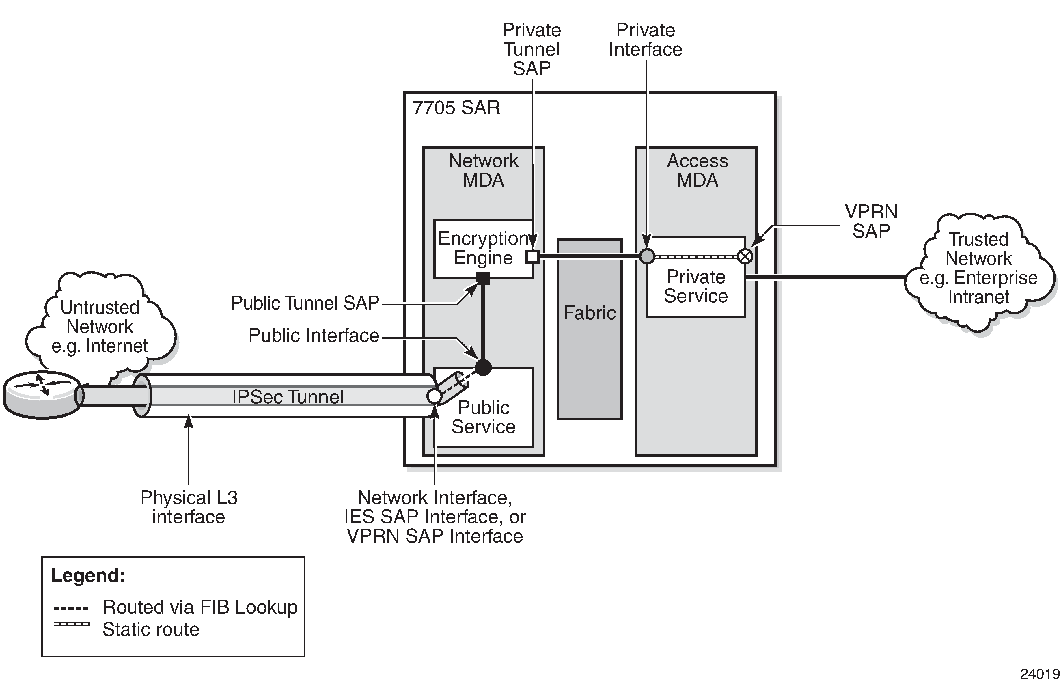
In IPSec Implementation Architecture , all ingress customer traffic from the trusted network is aggregated into the private VPRN service, where a VPRN static route directs the traffic into the encryption engine. The encryption engine encrypts the customer traffic using configurable encryption and authentication protocols, and adds the IPSec tunnel outer IP header. The source IP address of the outer IP header is the local security gateway address, and the destination IP address is the peer security gateway address.
The encrypted IPSec packet exits the node via an IES, VPRN, or router interface that is configured on an encryption-capable adapter card; it gets routed to its destination via a standard FIB lookup.
IPSec traffic ingressing a public-side VPRN that is not configured for IPSec is dropped.
If the traffic passes all security checks, it is decrypted and the customer traffic is routed through the associated VPRN. Any traffic that does not match the tunnel security configuration is dropped.
Hardware Support
The 7705 SAR supports IPSec on the following nodes and adapter cards:
7705 SAR-8 Shelf V2 or 7705 SAR-18 with one of the following:
2-port 10GigE (Ethernet) Adapter card
6-port Ethernet 10Gbps Adapter card
8-port Gigabit Ethernet Adapter card, version 3
10-port 1GigE/1-port 10GigE X-Adapter card, version 2 (supported on the 7705 SAR-18 only)
7705 SAR-Ax
7705 SAR-H
7705 SAR-Hc
7705 SAR-Wx
7705 SAR-X
IPSec Encryption Features
IPSec provides a variety of encryption features required to establish bidirectional IPSec tunnels, including:
Control plane:
manual keying
dynamic keying: Internet key exchange version 1, version 2 (IKEv1, IKEv2)
IKEv1 mode: main or aggressive
authentication: pre-shared-key (PSK)
perfect forward secrecy (PFS)
dead peer detection (DPD)
NAT-traversal (NAT-T)
security policy
Data plane:
encapsulating security payload (ESP) (with authentication) tunnel mode
IPSec transform (NULL cannot be used for authentication and encryption at the same time):
authentication algorithm: NULL, MD5, SHA1, SHA256, SHA384, SHA512, auth-encryption
encryption algorithm: NULL, DES, 3DES, AES128, AES192, AES256, AES128-GCM8, AES128-GCM12, AES128-GCM16, AES192-GCM8, AES192-GCM12, AES192-GCM16, AES256-GCM8, AES256-GCM12, AES256-GCM16
IPSec IKE policy (NULL is not supported):
authentication algorithm: MD5, SHA1, SHA256, SHA384, SHA512, auth-encryption
encryption algorithm: DES, 3DES, AES128, AES192, AES256, AES128-GCM8, AES128-GCM16, AES256-GCM8, AES256-GCM16
PRF algorithm: MD5, SHA1, SHA256, SHA384, SHA512, AES-XCBC, same-as-auth
DH-Group: 1, 2, 5, 14, 15
The 7705 SAR uses a configured authentication algorithm in an IKE policy for the pseudorandom function (PRF).
When using AES-GCM encryption algorithms, use either the default value for the isakmp-lifetime command or a value that is lower than the default. This ensures that the CHILD_SA lifetime is refreshed for AES-GCM at least once a day.
The 7705 SAR supports the use of IPSec and segment routing with entropy label for:
IPSec over BGP 3107 over segment routing with entropy label
IPSec over static route over segment routing with entropy label
VLL over GRE over IPSec over BGP 3107 over segment routing with entropy label
VLL over GRE over IPSec over static route over segment routing with entropy label
SHA2 Support
The 7705 SAR supports RFC 4868. For data origin authentication and integrity verification functions in the IKEv1 or IKEv2 and ESP protocols, the 7705 SAR supports the following HMAC-SHA-256+ algorithms:
AUTH_HMAC_SHA2_256_128
AUTH_HMAC_SHA2_384_192
AUTH_HMAC_SHA2_512_256
For pseudorandom functions (PRF) with IKEv1 or IKEv2, the 7705 SAR supports the following HMAC-SHA-256+ algorithms:
PRF_HMAC_SHA2_256_128
PRF_HMAC_SHA2_384_192
PRF_HMAC_SHA2_512_256
IPSec Security Policy, IKE Policy, and IPSec Transform
An IPSec security policy defines the type of traffic allowed to pass in or out of an IPSec tunnel. The policy does this through the configuration of local and remote IP address pairs. The behavior of an IPSec security policy is similar to IP filtering. IPSec security policies are created for a VPRN service context and applied to an IPSec tunnel in that service.
An IKE policy defines how the 7705 SAR encrypts and authenticates an IPSec tunnel that uses that policy. Its configuration includes specifics on Diffie-Hellman key derivation algorithms, encryption and authentication protocols to be used for establishing phase 1 and phase 2 security associations, and so on.
An IPSec transform defines the algorithms used for IPSec SA. The transform configuration dictates the algorithms that customer traffic uses for encryption and authentication.
IKEv2 Fragmentation
IKEv2 uses UDP as the transport protocol for its messages. Most IKEv2 messages are relatively small. In some cases, though, an IKEv2 message can be large; for example, an IKE_AUTH message with a certificate payload. If the IKEv2 message size exceeds the network path MTU, it gets fragmented at the IP level into smaller IP fragments. However, some devices (such as firewalls) do not allow IP fragments to pass through the network. If the fragments do not pass through, IKE negotiation fails.
To address this problem, the 7705 SAR supports IKEv2 fragmentation, as specified in RFC 7383. With IKEv2 fragmentation, IKEv2 messages are fragmented at the IKEv2 protocol level into smaller messages. The resulting IP packets are smaller than the network path MTU and are therefore not fragmented through the network and can traverse network devices that do not allow IP fragments to pass through.
IKEv2 fragmentation is enabled in the ike-policy context by configuring the ikev2-fragment command with an MTU. The MTU specified is the maximum size of the IKEv2 packet.
The system enables IKEv2 fragmentation for a tunnel only if the ikev2-fragment command is configured and if the peer also announces its support by sending an IKEV2_FRAGMENTATION_SUPPORTED notification.
Tunnel Group
A tunnel group is a collection of IPSec tunnels. The 7705 SAR supports one tunnel group that always uses tunnel ID 1.
Tunnel Interfaces and SAPs
There are two types of tunnel interfaces and associated SAPs:
public tunnel interface: configured on the public-side IES or public-side VPRN service; outgoing tunnel packets have a source IP address (local gateway address) in this subnet
public tunnel SAP: associated with the public tunnel interface
private tunnel interface: configured on the private-side VPRN service
- private tunnel SAP: associated with the private tunnel interface, logically linked to the public tunnel SAP
Public Tunnel SAPs
An IES or VPRN service (the delivery service) must have at least one IP interface associated with a public tunnel SAP to receive and process the following types of packets associated with IPSec tunnels:
IPSec ESP (IP protocol 50)
IKEv1/v2 (UDP)
The public tunnel SAP type has the format tunnel-tunnel-group-id.public:tag, where tunnel-group-id is always 1. See Configuring IPSec and IPSec Tunnels in Services for a CLI configuration example.
Private Tunnel SAPs
The private (VPRN) service must have an IP interface to an IPSec tunnel in order to forward IP packets into the tunnel, causing them to be encapsulated according to the tunnel configuration, and to receive IP packets from the tunnel after the encapsulation has been removed (and decrypted). That IP interface is associated with a private tunnel SAP.
The private tunnel SAP has the format tunnel-tunnel-group-id.private:tag, where tunnel-group-id is always 1. The tunnel keyword must be used when creating the private tunnel interface. See Configuring IPSec and IPSec Tunnels in Services for a CLI configuration example.
IP Interface Configuration
The IP MTU of a private tunnel SAP interface can be configured. This sets the maximum payload IP packet size (including IP header) that can be sent into the tunnel and applies to the packet size before the tunnel encapsulation is added. When an IPv4 payload packet that needs to be forwarded to the tunnel is larger than M bytes, one of the following behaviors occurs.
If the DF bit is clear (not set), the payload packet is fragmented to the MTU size before tunnel encapsulation.
If the DF bit is set, the payload packet is discarded and (if allowed by the ICMP setting of the sending interface) an ICMP type 3/code 4 is returned to the sender (with the MTU of the private tunnel SAP interface in the payload).
IPSec Tunnel Configuration
To bind an IPSec tunnel to a private tunnel SAP, the ipsec-tunnel command is configured under the SAP context, where the ipsec-tunnel context provides access to the following parameters:
security policy
local gateway address
dynamic keying
IKE policy
pre-shared key
transform
The local gateway address must belong to the same subnet as the delivery-service (IES or VPRN) public tunnel interface address. The local gateway address and peer gateway address are the source and destination addresses for the outgoing IPSec traffic.
A private tunnel SAP can have only one IPSec tunnel.
IPSec over MPLS with Public Service IES
IPSec messages can be routed over MPLS tunneled routes. The 7705 SAR supports resolution of IPSec routes to the secure gateway address by using either BGP 3107 label routes or IGP shortcuts. When BGP learns IPv4 addresses as 3107 label routes, BGP resolves the next hops for these routes with an LDP or RSVP-TE tunnel. These BGP routes create BGP tunnels that can be used to resolve an IPSec secure gateway address. When an IGP shortcut is enabled on the 7705 SAR by using the config>router>ospf>rsvp-shortcut command, OSPF installs an OSPF route in the RIB, with an RSVP-TE LSP as the next hop. If this OSPF route is determined as the overall best route, then the next hop is an RSVP-TE tunnel. For information about setting up BGP 3107 label routes or IGP shortcuts to resolve IPSec routes, see Configuring IPSec over MPLS.
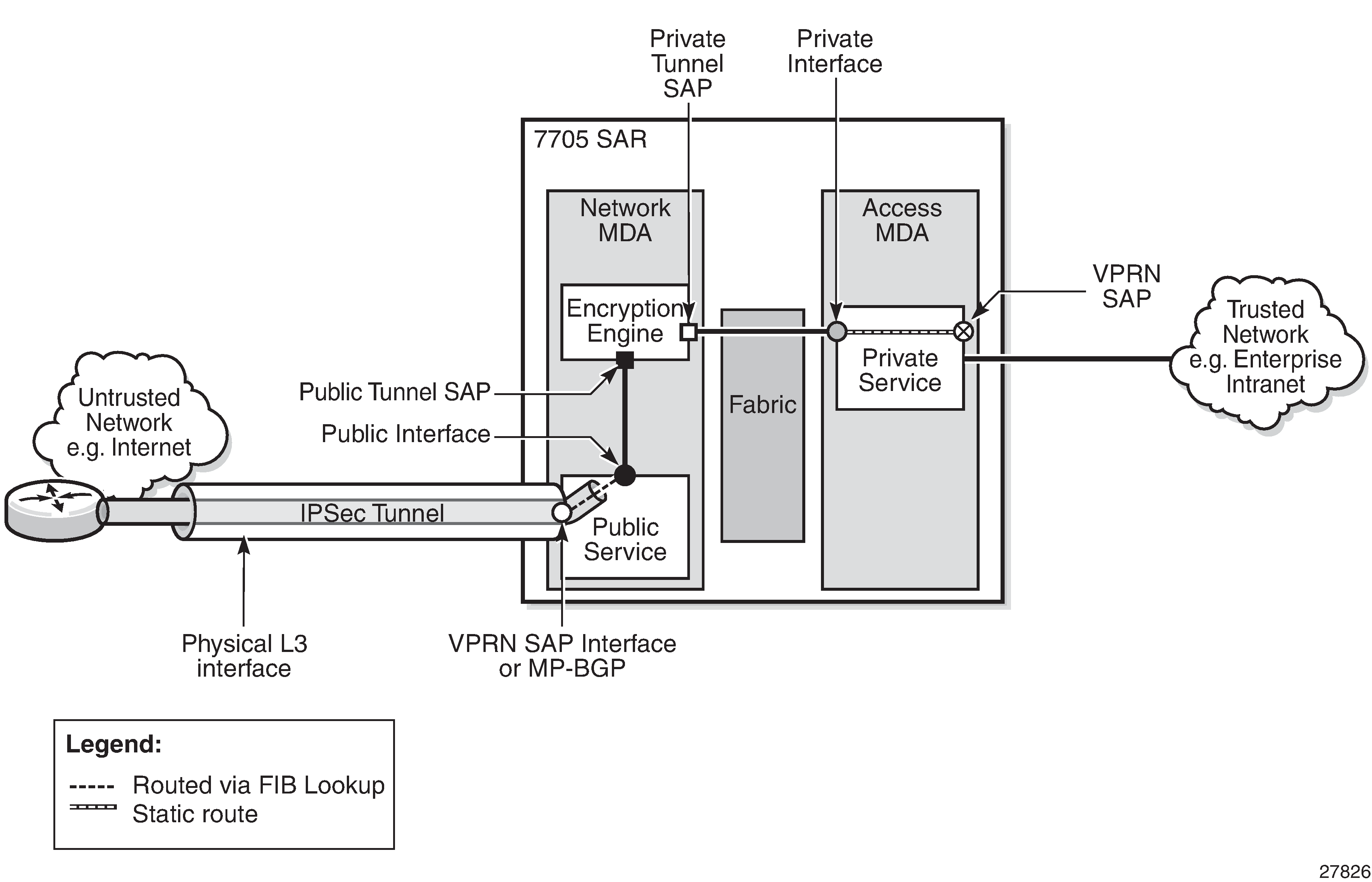
IPSec Transport Tunnels with Public Service VPRN
Configuring VPRN as the public-side service of an IPSec tunnel ensures that IPSec traffic from different customers arriving at the 7705 SAR is kept separate. Keeping the traffic from different customers separated gives service providers another layer of security because a specific VPRN is assigned to a specific customer, and only the IPSec tunnels encrypted by that customer arrive on that VPRN. In contrast, when IES is used for the public-side service of an IPSec tunnel, all IPSec traffic arrives in the GRT and fans out to its corresponding private service through the IPSec public gateway.
When the public-side service of an IPSec tunnel is a VPRN, IPSec traffic is transported over MPLS or GRE. The 7705 SAR supports the transport of GRE-encapsulated VLLs (Cpipes and Epipes) over IPSec tunnels that use VPRN as the public-side service of the IPSec tunnel.
MP-BGP services can be provisioned using auto-bind tunnels or SDPs to push IPSec packets over MPLS or GRE transport tunnels.
An MP-BGP VC label is pushed on top of the IPSec packet and a transport tunnel label is pushed next. The transport tunnel can include BGP-labeled unicast (BGP-LU) routes (3107 label routes).
VPRN Public Service IPSec Transport Tunnels shows the concept of a VPRN as the public-side service of an IPSec tunnel.
GRE-Encapsulated VLLs/VPLS over IPSec VPNs
The 7705 SAR can provide secure transport of Cpipe, Epipe, and VPLS traffic by routing it as GRE-encapsulated traffic over IPSec VPNs. This is achieved by enabling route processing in the GRT FIB through a GRT lookup at ingress to the VRF and GRT leaking at egress from the VRF. The 7705 SAR leaks only IPSec tunnels into the GRT as the available next hop; no other tunnel type is leaked from the VRF into the GRT as a next hop. This route processing is enabled with the config>service>vprn>grt-lookup>enable-grt command.
When a packet arrives at the VRF and the grt-lookup>enable-grt command is configured, the following sequence occurs.
The packet undergoes a route lookup in the VRF FIB to determine the next hop.
If there is no matching route found in the VRF, a route lookup is then performed in the GRT FIB.
If there is a match for the route in the GRT FIB and the packet is:
an IP packet with a local address, it is extracted to the CSM and processed as a management packet
a GRE packet with a local address, it is processed as a service packet
an IP or GRE packet with no local address, it is routed to the available next hop as found in the GRT FIB
In order for a packet to leave the VRF, the route that needs to be resolved — the destination prefix — must be leaked to the GRT. The destination prefix is configured in a route policy using the config>router>policy-options>prefix-list command; that policy is then leaked into the GRT by referencing it in the config>service>vprn>grt-lookup>export-grt command. Packets with the matching route found in the GRT FIB are routed via the IPSec tunnel configured within the VPN.
The 7705 SAR supports the following packet types for GRT lookup in the VRF FIB:
self-generated GRE packets for Cpipe, Epipe, and VPLS traffic
self-generated IP packets for management, BGP, and T-LDP traffic
transiting GRE packets over access and network interfaces
transiting IP packets over access or network interfaces
The 7705 SAR supports the following packets types arriving in the VRF via the IPSec tunnel:
IP packets, including management packets, with a local address
GRE packets with a local address
transiting IP packets via the GRT lookup
transiting GRE packets via the GRT lookup
The 7705 SAR terminates GRE packets at a system IP address or any local interface IP address. When GRE-encapsulated packets are transported over an IPSec VPN, the IPSec tunnel can terminate on a 7705 SAR or 7750 SR and the GRE packets are processed on the secure gateway.
When configuring grt-lookup, the config>service>vprn>static-route-entry>grt command must be configured for the local IP address that will be looked up in the GRT. The next hop is set to the desired local IP address and is used on ingress to force a second route lookup in the GRT. If that lookup is successful, and the packet is a GRE packet destined to a local interface, it is forwarded for PW processing. If the packet is destined to a system IP address and is not GRE packet, it is forwarded for management processing. A second static route is required in the IPSec VPN in order to point the far-end IP address to the IPSec tunnel. It is used on egress and is configured for the far-end IP address with a next hop set to the IPSec tunnel.
By enabling GRT lookup, signaling packets such as T-LDP can be routed securely between two system IP addresses by using the IPSec tunnel. However, IGP protocols such as OSPF or IS-IS, which use a multicast destination, cannot use the IPSec tunnel.
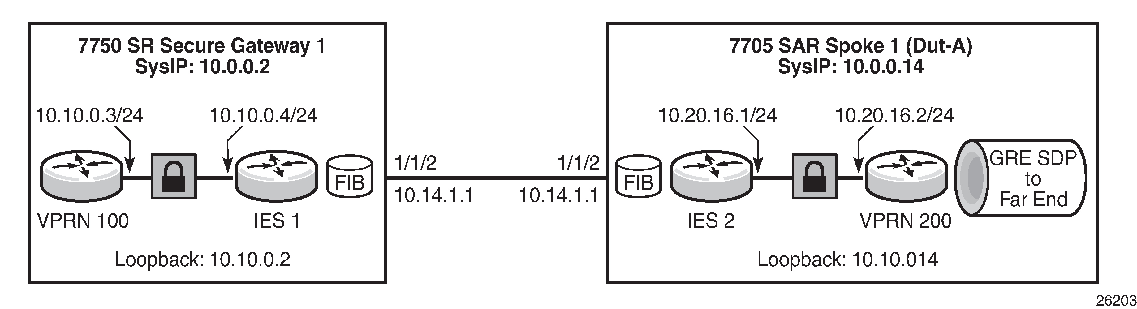
Routing GRE-Encapsulated Packets over IPSec shows an example of route leaking configured to resolve the far-end system IP address 10.0.0.2 using an IPSec VPN. Although the example shows GRE to a system IP address on the 7705 SAR for illustrative purposes, GRE to any other local IP address on the 7705 SAR can be substituted.
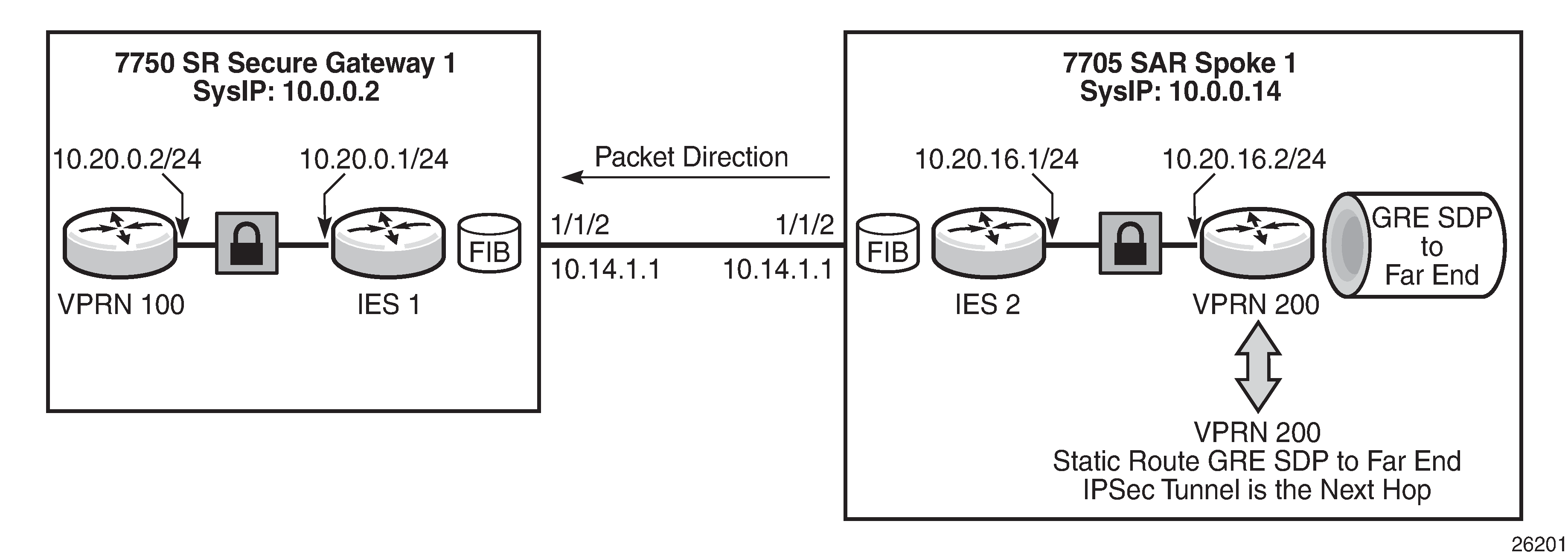
Based on Routing GRE-Encapsulated Packets over IPSec, the CLI example below shows the configuration of a routing policy that is used to leak the far-end system IP address into the GRT. The command config>router>policy-options>prefix-list>prefix creates a prefix entry with the system IP address of the far-end node (10.0.0.2/32) in the route policy prefix list. The policy option is configured using the prefix specified above (10.0.0.32) with the action accept. The policy preference should be set so that it is lower than the IGP advertised preference.
#--------------------------------------------------
*A:7705:Dut-A>config>router>policy-options# info
#--------------------------------------------------
            prefix-list "grt"
                prefix 10.0.0.2/32 exact
            exit
            policy-statement "grt"
                entry 1
                    from
                        prefix-list "grt"
                    exit
                    action accept
                        local-preference 3
                        preference 3
                        metric-set 1
                    exit
                exit
The far-end system IP address 10.0.0.2 is resolved using a static route configured with an IPSec tunnel next hop of ‟tunnel2”. The GRT lookup at the ingress VRF is enabled using the config>service>vprn>grt-lookup>enable-grt command and a second static route is configured to enable lookup at ingress for the local system IP address 10.0.0.14/32, as shown in the CLI example below:
#--------------------------------------------------
*A:7705:Dut-A>config>sevice>vprn# info
#--------------------------------------------------
            static-route-entry 10.10.0.2
                ipsec-tunnel "tunnel2"
                    no shutdown
                exit
            exit
            static-route-entry 10.0.0.14/32
                grt
                    no shutdown
                exit
            exit
            grt-lookup
                enable-grt
                export-grt grt
                    exit
                exit
            exit
The far-end system IP address with a next hop IPSec tunnel (‟tunnel2”) is leaked into the GRT using the command config>service>vprn>grt-lookup>export-grt, referencing the routing policy configured above (‟grt”).
A GRE-encapsulated SDP to the far-end system IP address is configured using the commands config>service>sdp sdp-id gre create and config>service>sdp>far-end. A Cpipe, Epipe, or VPLS is then configured using that SDP. For information about configuring a Cpipe or Epipe, see Configuring a VLL Service with CLI and Configuring VLL Components in this guide. For information about configuring a VPLS, see Configuring a VPLS Service with CLI in this guide.
For information about GRT lookup for management traffic, see ‟In-Band Management using a VPRN” in the VPRN Services chapter of this guide.
GRE-Encapsulated VLLs/VPLS over IPSec over MPLS
The 7705 SAR can route Cpipe, Epipe, or VPLS traffic over IPSec using either BGP 3107 Label routes or RSVP-TE IGP shortcuts.
When GRE-encapsulated Cpipe, Epipe, or VPLS traffic is routed over IPSec, the GRE packets and T-LDP packets can be routed to the far-end system IP address using the IPSec tunnel. However, there must be special consideration for the MPLS tunnel, in particular for BGP 3107 label routes using IBGP, because MPLS signaling packets cannot use an IPSec tunnel.
VLLs/VPLS over IPSec over MPLS (Using BGP 3107 Label Routes) Solution 1: Changing BGP Signaling to Loopback Interface
When resolving an IPSec route to the secure gateway address with a BGP 3107 label route, BGP can be set up to use either IBGP or EBGP.
The IBGP 3107 label route is usually set up to the system IP address. However, the Layer 2 services to be protected by IPSec are also set up to the system IP address. In this case routing the IBGP 3107 label routes via the IPSec tunnel creates some complexities.
To avoid routing both Layer 2 services and the IBGP (used for 3107) over the IPSec tunnel, IBGP should be setup to a loopback interface instead of to the system IP address. Also, all MPLS LSPs that resolve these 3107 labels should be setup to the same loopback interface. For RSVP-TE this means the far end has to be the loopback interface and for LDP this means an originate-fec needs to be configured to the loopback interface.
VLL/VPLS over IPSec over MPLS Using BGP 3107 Label Routes shows an example of a BGP 3107 label route configured with a loopback interface.
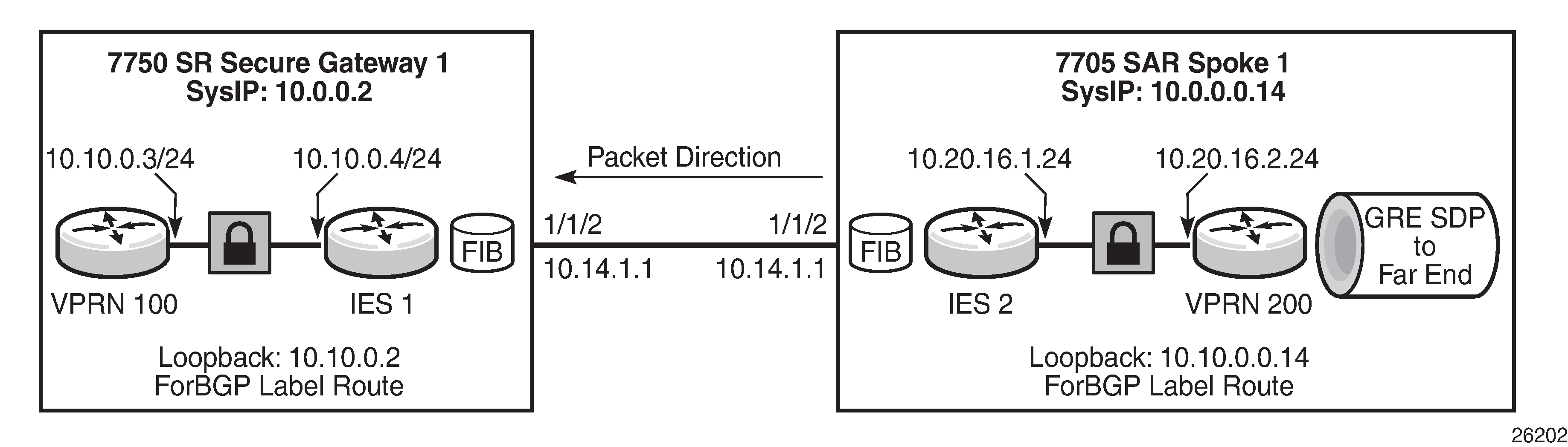
Based on VLL/VPLS over IPSec over MPLS Using BGP 3107 Label Routes, the CLI example below shows BGP configured to a neighbor loopback address and the BGP local address configured as a local loopback address. BGP for 3107 label route advertisement is enabled using the advertise-label ipv4 keyword.
#--------------------------------------------------
*A:7705:Dut-A>config>router>bgp# info
#--------------------------------------------------
            local-as 10
            group ‟2”
               peer-as 10
               local-address 10.10.0.14
               neighbor 10.10.0.2
                    family vpn-ipv4
                    export ‟gw”
                    advertise-label ipv4
               exit
            exit
            no shutdown
In addition, IGP must be configured to make the loopback IP addresses reachable for BGP.
The BGP 3107 label route can be resolved with either an LDP or an RSVP-TE tunnel. To use an LDP tunnel, an LDP FEC must be configured to advertise the local loopback IP address to the neighbor, as shown in the CLI example below:
#--------------------------------------------------
*A:7705:Dut-A>config>router>ldp# info
#--------------------------------------------------
            fec-originate 10.10.0.14/32 advertised-label 32 pop
To use an RSVP-TE tunnel, an LSP is created to the neighbor loopback IP address, as shown in the CLI example below:
#--------------------------------------------------
*A:7705:Dut-A>config>router>mpls# info
#--------------------------------------------------
            lsp ‟to-14-loop”
               to 10.10.0.2
               cspf
               no shutdown
            exit
With EBGP, BGP communicates between the local and neighbor IP interface so IGP is not required to resolve the BGP 3107 label routes. In the example shown in VLL/VPLS over IPSec over MPLS Using BGP 3107 Label Routes, the configuration would use Layer 3 interfaces instead of loopback addresses, as shown in the CLI example:
#--------------------------------------------------
*A:7705:Dut-A>config>router>bgp# info
#--------------------------------------------------
            local-as 10
            group ‟2”
               peer-as 10
               neighbor 10.14.1.2
                    family vpn-ipv4
                    export ‟gw”
                    advertise-label ipv4
               exit
            exit
            no shutdown
To use an LDP tunnel, an LDP FEC is configured to advertise the local interface IP address:
#--------------------------------------------------
*A:7705:Dut-A>config>router>ldp# info
#--------------------------------------------------
            fec-originate 10.14.2.2/32 advertised-label 32 pop
To use an RSVP-TE tunnel, an LSP is created to the neighbor interface IP address:
#--------------------------------------------------
*A:7705:Dut-A>config>router>mpls# info
#--------------------------------------------------
            lsp ‟to-14-loop”
               to 10.14.1.2
               cspf
               no shutdown
            exit
VLLs/VPLS over IPSec over MPLS (Using BGP 3107 label Routes) Solution 2: GRE to Local Interface on 7705 SAR
When transporting a GRE-encapsulated VLL or VPLS over IPSec over MPLS, the 7705 SAR can terminate the GRE tunnel to a loopback address. In this scenario, the VLL or VPLS is created between the loopback interfaces and the BGP 3107 label route uses the system IP address to resolve the IPSec gateway. This relies on GRT lookup and leaking, but the far-end loopback IP address is used instead of the system IP address in the routing policy. VLL/VPLS over IPSec over MPLS using a Loopback Address shows an example of VLL/VPLS over IPSec over MPLS using a loopback address, followed by CLI configuration examples.
Based on VLL/VPLS over IPSec over MPLS using a Loopback Address, a local loopback interface is configured on the 7705 SAR:
#--------------------------------------------------
*A:7705:Dut-A>config>router# info
#--------------------------------------------------
            interface "loop1"
                address 10.10.0.14
                loopback
                no shutdown
            exit
T-LDP signaling is configured to the far-end loopback IP address:
#--------------------------------------------------
*A:7705:Dut-A>config>router>ldp# info
#--------------------------------------------------
            targeted-session
                peer 10.10.0.2
                  local-lsr-id ‟loop1”
                  no shutdown
                exit
            exit
A routing policy is configured on the 7705 SAR using the loopback address of the secure gateway:
#--------------------------------------------------
*A:7705:Dut-A>config>router>policy-options# info
#--------------------------------------------------
            prefix-list "loop"
                prefix 10.10.0.2/32 exact
            exit
            policy-statement "loop"
                entry 1
                    from
                        prefix-list "loop"
                    exit
                    action accept
                        local-preference 3
                        preference 3
                        metric-set 1
                    exit
                exit
            exit
The routing policy is then used to enable GRT lookup and leaking in the VPRN:
#--------------------------------------------------
*A:7705:Dut-A>config>sevice>vprn# info
#--------------------------------------------------
            static-route-entry 10.10.0.2
                ipsec-tunnel "tunnel2"
                    no shutdown
                exit
            exit
            static-route-entry 10.0.0.14/32
                grt
                    no shutdown
                exit
            exit
            grt-lookup
                enable-grt
                export-grt loop
                    exit
                exit
            exit
The GRE SDP is then created to the far-end loopback IP address:
#--------------------------------------------------
*A:7705:Dut-A>config>sevice# info
#--------------------------------------------------
            sdp 200 gre create
               far-end 10.10.0.2
               keep-alive
                  shutdown
               exit
               no shutdown
            exit
VLLs/VPLS over IPSec over MPLS (Using IGP Shortcuts)
BGP can route VLL or VPLS traffic over an IPSec VPN using an IGP shortcut to resolve the secure gateway address, as described in Configuring IPSec over MPLS. Although the VLL or VPLS traffic destined for the far-end system IP address are routed using an IPSec tunnel, the IGP packets themselves are destined for a multicast address and are not resolved over the IPSec tunnel.
X.509v3 Certificate Overview
X.509v3 is an ITU-T standard that consists of a hierarchical system of certificate authorities (CAs) that issue certificates that bind a public key to particular entity’s identification. The entity’s identification could be a distinguished name or an alternative name, such as a fully qualified domain name (FQDN) or an IP address.
An end entity (EE) is an entity that is not a CA. For example, an end entity can be a web server, a VPN client, or a VPN gateway.
A CA issues a certificate by signing an entity’s public key with its own private key. A CA can issue certificates for an end entity as well as for another CA. When a CA certificate is issued for itself (signed by its own private key), this CA is called the root CA. Therefore, an end entity’s certificate can be issued by the root CA or by a subordinate CA (that is, issued by another subordinate CA or root CA). When there are multiple CAs involved, this is called a chain of CAs.
In addition to issuing certificates, the public key infrastructure (PKI) also includes a mechanism for revoking certificates because of reasons such as a compromised private key.
A certificate can be used for authentication. Typically, the certificate authentication process functions as follows.
The system trusts a CA as the trust anchor CA (which typically is a root CA). This means that all certificates issued by a trust anchor CA, or the certificates issued by a subordinate CA that have been issued by the trust anchor CA, are consider trusted.
A peer that is to be authenticated presents its certificate along with a signature over some shared data between the peer and system, and the certificate is signed using a private key.
The signature is verified by using the public key in the certificate. In addition, the certificate itself is verified as being issued by the trust anchor CA or a subordinate CA that is part of the chain leading up to the trust anchor CA. The system can also check if the peer’s certificate has been revoked. Only when all these verifications succeed does the certificate authentication succeed.
X.509v3 Certificate Support on the 7705 SAR
The 7705 SAR PKI implementation supports the following features:
certificate enrollment:
locally generated RSA/DSA key
offline enrollment via PKCS#10 (public key cryptography standards)
online enrollment via CMPv2
support for CA chain
certificate revocation check:
certificate revocation list (CRL) for both EE and CA certificates
online certificate status protocol (OCSP) for EE certificate only
Local Storage
The 7705 SAR requires the following objects to be stored locally as a file:
CA certificate
CRL
the system’s own certificate
the system’s own key
All these objects must be imported with the admin certificate import command before they can be used by the 7705 SAR. The import process converts the format of the input file to distinguished encoding rules (DER), encrypts the key file, and saves it in the cf3:/system-pki directory.
The imported file can also be exported using a specified format by means of the admin certificate export command.
The admin certificate import and admin certificate export commands support the following formats:
certificates can be imported and exported using the following formats:
PKCS #12
PKCS #7 (DER and PEM) (privacy enhanced mail)
PEM
DER
If there are multiple certificates in the file, only the first one is used.
key pairs can be imported and exported using the following formats:
PKCS #12
PEM
DER
the CRL can be imported and exported using the following formats:
PKCS #7 (DER and PEM)
PEM
DER
The PKCS #12 file can be encrypted with a password.
CA Profile
On the 7705 SAR, the CA-related configuration is stored in a CA profile that contains the following configurable items:
name and description
CA’s certificate — an imported certificate
CA’s CRL— an imported CRL
revocation check method — specifies the way the CA checks the revocation status of the certificate it issued
CMPv2 — a CMPv2 server-related configuration
OCSP— an OCSP responder-related configuration
When a user enables a ca-profile (no shutdown), the system loads the specified CA certificate and CRL into memory. The following checks are performed:
for the CA certificate:
all mandatory fields defined in section 4.1 of RFC 5280, Internet X.509 Public Key Infrastructure Certificate and Certificate Revocation List (CRL) Profile, exist and conform to the RFC 5280 defined format
the version field value is 0x2
the validity field indicates that the certificate is still in its validity period
the X.509 Basic Constraints extension exists and the CA Boolean value is true
if the Key Usage extension exists, at the least), the keyCertSign and cRLSign are asserted
for the CRL:
all mandatory fields defined in section 5.1 of RFC 5280 exist and conform to the RFC 5280 defined format
if the version field exists, the value is 0x1
the delta CRL indicator does not exist (delta CRL is not supported)
the CRL is signed by the configured CA certificate
The CRL is required in order to enable ca-profile.
CA Chain Computation
When verifying a certificate with a CA or a chain of CAs, the system must identify the issuer CA of the certificate. The 7705 SAR looks through all configured CA profiles to find the issuer CA. The following is the method that the system uses to find the issuer CA:
the issuer CA’s certificate subject must match the issuer field of the certificate in question
if present, the authority key identifier of the certificate in question must match the subject key identifier of the issuer CA’s certificate
if present, the key usage extension of the issuer CA’s certificate must permit certificate signing
Certificate Enrollment
The 7705 SAR supports two certificate enrollment methods:
the offline method using PKCS #10
the online method using CMPv2
To use the offline method, perform the following steps:
Generate a key pair using the admin certificate gen-keypair command.
For example: admin certificate gen-keypair cf3:/segw.key size 2048 type rsa
Generate a PKCS#10 certificate signing request with the key generated in Step 1 using the admin certificate gen-local-cert-req command.
For example: admin certificate gen-local-cert-req keypair cf3:/segw.key subject-dn C=US,ST=CA,O=ALU,CN=SeGW domain-name segw-1.alu.com file cf3:/segw.pkcs10
As well as specifying the subject of the certificate request, you can optionally specify an FQDN and an IP address as SubjectAltName.
Import the key file using the admin certificate import command.
Example: admin certificate import type key input cf3:/segw.key output segw.key format der
Because the key is imported, remove the key file generated in Step 1 for security reasons.
Send the PKCS #10 file to the CA via an offline method such as email.
The CA signs the request and returns the certificate.
Import the returned certificate using the admin certificate import command.
Example: admin certificate import type cert input cf3:/segw.cert output segw.cert format pem
For the online method using CMPv2-based enrollment, see the Certificate Management Protocol Version 2 (CMPv2).
Certificate Revocation Check
A revocation check is a process that checks whether a certificate has been revoked by the issuer CA.
The 7705 SAR supports two methods for the certificate revocation check:
CRL
OCSP
The CRL can be used for both EE and CA certificate checks, while OCSP can only be used for an EE certificate check.
For an IPSec application, users can configure multiple check methods with a priority order for an EE certificate. Using the status-verify command in the ipsec-tunnel configuration context, users can configure a primary method, a secondary method, and a default result. The primary and secondary methods can be either OCSP or CRL. The default result is either good or revoked. If the system does not get an answer from the primary method, it falls back to the secondary method. If the secondary method does not return an answer, the system uses the default result.
By default, the system uses the CRL to check the revocation status of a certificate, whether it is an end entity certificate or a CA certificate. This makes the CRL a mandatory configuration in the ca-profile.
This behavior can be changed using the revocation-check crl-optional command under the ca-profile context, for the CA certificate only. As an example, if the IPSec application needs to use the CRL of a specific ca-profile to check the revocation status of an end entity certificate and the CRL is nonexistent for any reason, this is treated as the system being unable to get an answer from the CRL, and the system falls back to either the secondary method or the default-result configured under the status-verify context.
If the system needs to check the revocation status of a CA certificate in a certificate chain and the CRL is nonexistent for any reason, the system skips checking the revocation status of the CA certificate. For example, certificate CA1 is issued by certificate CA2. If CA2’s revocation-check is crl-optional and CA2’s CRL is nonexistent, the system does not check the revocation status of certificate CA1 and considers it to be good.
For details about OCSP, see OCSP.
Certificate, CRL, and Key Cache
Configured certificates, CRLs, and keys are cached in memory before they are used by the system.
Every certificate, CRL, and key has one system-wide cache copy.
For a CA certificate and a CRL, the cache is created when there is a CA profile and when a no shutdown is performed and removed.
For an IPSec tunnel using legacy cert and key configurations, the cache is created only when the first tunnel using the cache is in a no shutdown state, and it is cleared when the last tunnel that used it is shut down.
For an IPSec tunnel using a cert-profile, the cache is created when the first cert-profile using the cache is in a no shutdown state, and it is removed when the last cert-profile that used it is shut down.
If a certificate or key is configured with both a cert-profile and legacy cert or key command, the cache is created when the first object (an ipsec-tunnel or a cert-profile) using it is in a no shutdown state, and it is removed when the last object using it is shut down.
To update a certificate or key without a shutdown ca-profile or ipsec-tunnel, the CLI command admin>certificate>reload manually reloads the certificate and key cache.
Using Certificates For IPSec Tunnel Authentication
The 7705 SAR supports X.509v3 certificate authentication for an IKEv2 tunnel (LAN-to-LAN tunnel and remote-access tunnel). The 7705 SAR also supports asymmetric authentication. This means that the 7705 SAR and the IKEv2 peer can use different methods to authenticate. For example, one side of the tunnel could use a pre-shared key and the other side could use a certificate.
The 7705 SAR supports certificate chain verification. For a static LAN-to-LAN tunnel, the command trust-anchor-profile specifies which CAs are expected to be present in the certificate chain before reaching the root CA (self-signed CA) configured in the system.
The key and certificate for the 7705 SAR are also configurable on a per-tunnel basis.
When using certificate authentication, the 7705 SAR uses the subject of the configured certificate as its ID by default.
Trust Anchor Profile
The 7705 SAR supports multiple trust anchors for each IPSec tunnel. A trust anchor profile can be configured with up to eight CAs. The system builds a certificate chain by using the certificate in the first certificate payload in the received IKEv2 message. If any of the configured trust anchor CAs in the trust anchor profile appear in the chain, then authentication is successful; otherwise, authentication fails.
Certificate Profile
The 7705 SAR supports sending different certificates and chains according to the received IKEv2 certificate-request payload. This is done by configuring a cert-profile that allows up to eight entries. Each entry includes a certificate and a key and, optionally, a chain of CA certificates.
The system loads the certificate and/or key in the cert-profile into memory and builds a compare-chain for the certificate configured in each entry of the cert-profile upon a no shutdown of the cert-profile. These chains are used for IKEv2 certificate authentication. If a chain computation cannot be completed for a configured certificate, the corresponding compare-chain will be empty or only partially computed.
Because there can be multiple entries configured in the cert-profile, the system must pick the certificate and key in the entry that the other side expects to receive. This is done by looking up the CAs within the received certificate request payload in the compare-chain and picking the first entry that has a certificate request CA appearing in its chain. If there is no such cert, the system picks the first entry in the cert-profile. The first entry is the first configured entry in the cert-profile. The entry-id of the first entry does not have to be ‟1”.
For example, assume there are three CAs listed in the certificate-request payload: CA-1, CA-2 and CA-3, and there are two entries configured in the cert-profile, as shown in the following configuration:
cert-profile ‟cert-profile-1”
  entry 1
    cert ‟cert-1”
    key ‟key-1”
  entry 2
    cert ‟cert-2”
    key ‟key-2”
    send-chain
      ca-profile ‟CA-1”
      ca-profile ‟CA-2”
The system builds two compare-chains: chain-1 for cert-1 and chain-2 for cert-2. Assume CA-2 appears in chain-2, but CA-1 and CA-3 do not appear in either chain-1 or chain-2. In that case, the system will pick entry 2.
After a certificate profile entry is selected, the system generates the AUTH payload by using the configured key in the selected entry. The system also sends the certificate in the selected entry as ‟certificate” payload to the peer.
If a chain is configured in the selected entry, one certificate payload is needed for each certificate in the configured chain. The first certificate payload in the IKEv2 message will be the signing certificate, which is configured by the cert command in the chosen cert-profile entry. In the preceding example, the system will send three certificate payloads: cert-2, CA-1, and CA-2.
The following CA chain-related enhancements are supported:
The no shutdown of a ca-profile triggers a recomputation of the compute-chain in related certificate profiles. The system also generates a new log-1 to indicate that a new compute-chain has been generated; the log includes the CA profile names on the new chain. Another log, log-2, is generated if the send-chain in a cert-profile entry is not in a compute-chain due to this CA profile change. Another log is generated if the hash calculation for a certificate under a ca-profile has changed.
When performing a no shutdown command on a cert-profile, the system allows the CAs in the send-chain, not in the compute-chain. The system also generates log-2, as above.
The system allows changes to the configuration of the send-chain without shutting down cert-profile.
Certificate Management Protocol Version 2 (CMPv2)
CMPv2 is a protocol between a Certificate Authority (CA) and an end entity (EE) based on RFC 4210, Internet X.509 Public Key Infrastructure Certificate Management Protocol (CMP). It provides multiple certificate management functions, such as certificate enrollment and certificate update.
The 7705 SAR supports the following CMPv2 operations:
initial registration — the process by which the 7705 SAR enrolls a certificate with a certain CA for the first time, where:
a public/private key pair must be preprovisioned before enrollment by means of local generation or other methods
optionally, users can include a certificate or certificate chain in the extraCerts field of the initial registration request
key pair update — a process by which the 7705 SAR updates an existing certificate for any reason (for example, a refresh of a key or certificate before it expires)
certificate update — a process by which an initialized 7705 SAR obtains additional certificates
polling — in some cases, the CA may not immediately return the certificate for reasons such as ‟request processing needs manual intervention”. In such cases, the 7705 SAR supports polling requests and responds as described in Section 5.3.22, Polling Request and Response, in RFC 4210.
The following list provides implementation details:
HTTP is the only supported transport protocol for CMPv2. HTTP 1.1 and 1.0 are supported and configurable.
All CMPv2 messages sent by the 7705 SAR consist of only one PKI message. In all cases, the size of the sequence for PKI messages is 1.
Both password-based MAC and public key-based signature CMPv2 message protection are supported.
The 7705 SAR only allows one outstanding ir/cr/kur request for each CMPv2 server. That means that no new requests are allowed if a pending request is present.
OCSP
The Online Certificate Status Protocol (OCSP) is used by 7705 SAR applications to determine the revocation state of an identified certificate, based on RFC 2560, X.509 Internet Public Key Infrastructure Online Certificate Status Protocol - OCSP. Unlike the CRL, which relies on checking against an offline file, OCSP provides timely, online information regarding the revocation status of a certificate.
The 7705 SAR supports both the CRL and OCSP as the certificate revocation status checking method. For a given IPSec tunnel, the user can configure a primary method, a secondary method, and a default result to achieve a hierarchical fallback mechanism. If the primary method fails to return a result, the system falls back to the secondary method. If the secondary method fails, the system uses the default result.
The following list provides implementation details:
Only an OCSP client function is supported.
HTTP is the only supported transport protocol.
OCSP server access via a management routing instance is not supported.
The 7705 SAR does not sign an OCSP request.
The OCSP response must be signed. The system will verify the response by using the signer’s certificate included in the response. If there is no such certificate, the CA certificate in the ca-profile will be used.
If a nextUpdate exists in the OCSP response, the 7705 SAR checks the current time to determine if it is earlier than the nextUpdate. If yes, the response is valid; otherwise, the response is considered unreliable and the 7705 SAR moves to the next revocation checking method.
The revocation status result from a valid OCSP response is cached in the system.
OCSP can only be used to verify the revocation status of the EE certificate. The CRL is still needed to verify the status of a CA certificate.
Applications
Two mobile backhaul applications are described in this section:
Metrocell Deployment: a solution for providers who are looking for security in the transmission medium to manage remote private networks in a metrocell deployment. IPSec is used as an encrypted uplink for OAM and mobile traffic to connect the remote network to the MTSO. The 7705 SAR-initiated IPSec tunnels can provide a secure means for managing the 7705 SAR and any private network behind the 7705 SAR, while NAT can provide scalability of IPSec tunnels over a single public IP address.
Small Business Deployment: the use of LTE and IP NodeBs, as an alternative to PWs, to provide a better match for an operator’s choice of transport network (that is, IPSec over public network compared to MPLS/PWs over a private network)
Metrocell Deployment
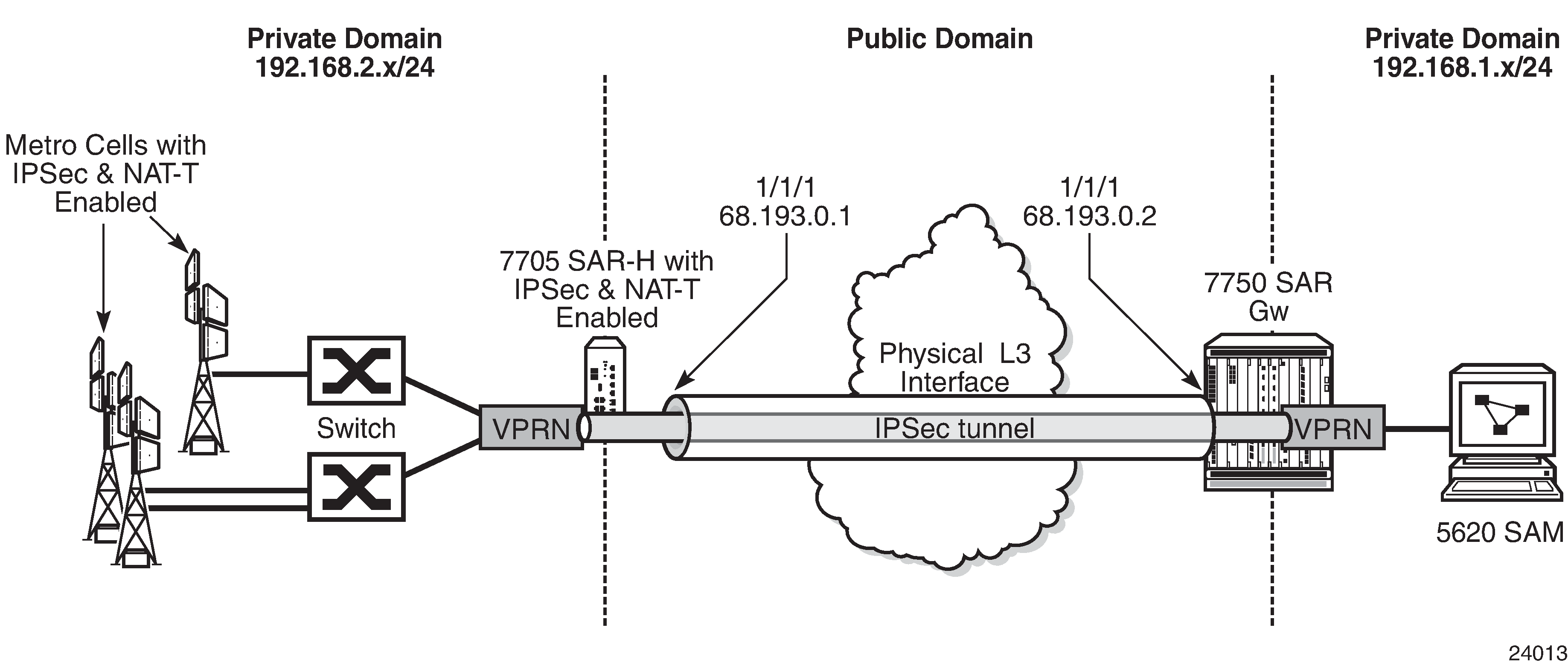
As shown in Typical Metrocell Deployment, in a typical metrocell deployment, the cell site network is divided into two separate segments: the private domain and the public domain. An IPSec tunnel generated from the 7705 SAR-H is used to backhaul the management and OAM traffic of the private network, including the management traffic of the switches and the 7705 SAR-H itself. All OAM traffic is aggregated within a VPRN service and uses the IPSec tunnel as the uplink tunnel to the 7750 SR gateway.
Small Business Deployment
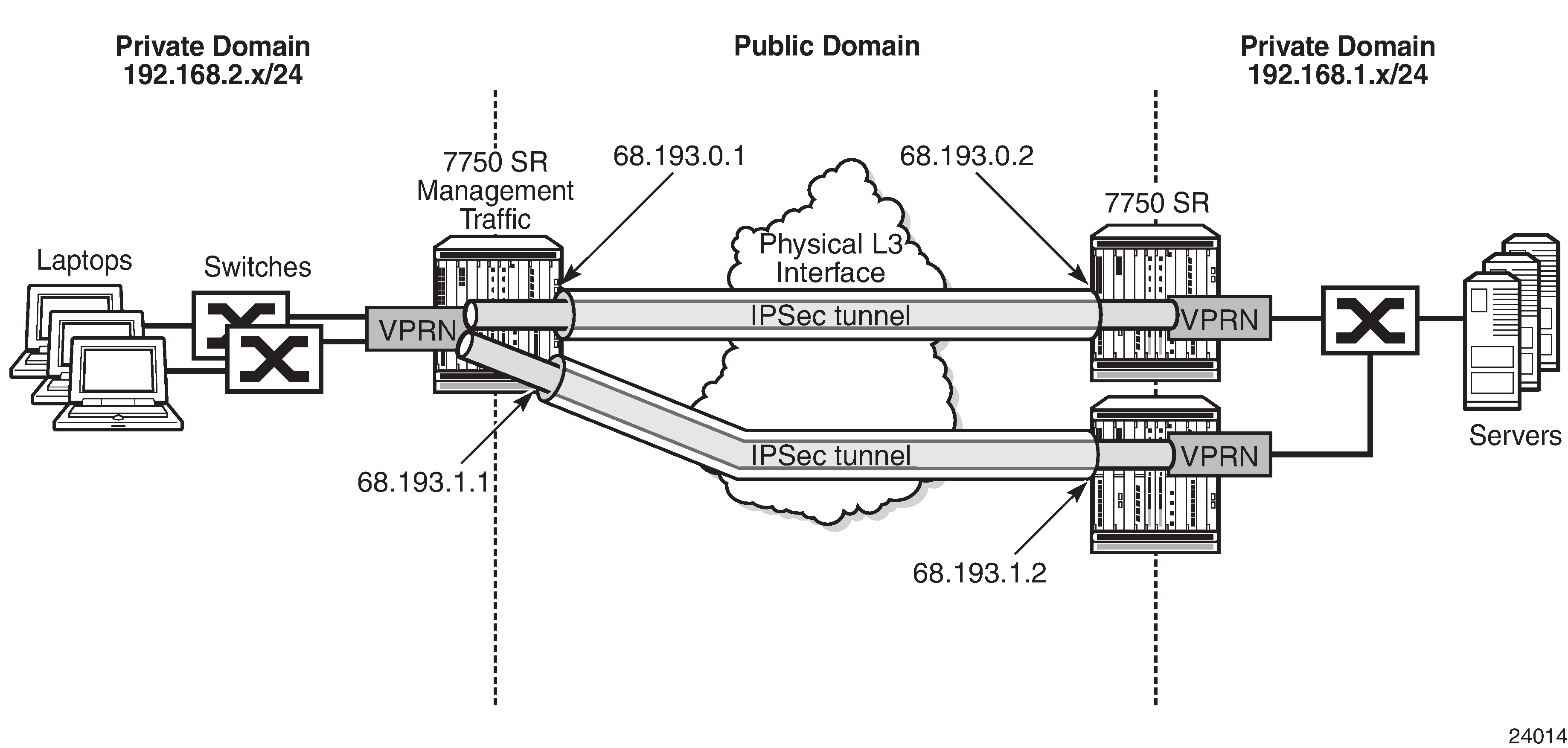
In a small business deployment, the network is usually designed with a hub and spoke topology. The spoke sites connect to the hub through a leased line or a public non-secure domain. IPSec provides the security and encryption needed to connect the spoke sites to the centralized office (hub). The hub and spoke topology in a small business deployment is favorable because of the security that the hub side can provide to the entire network. IPS/IDS and anti-virus appliances can be deployed to the hub site, which examines arriving traffic from the spoke sites. SPAM and viruses can be filtered out on the hub site by these appliances. If additional spoke-to-spoke connectivity is required, then additional IPSec tunnels can be established. See Typical Small Business Deployment.
NAT-Traversal for IKEv1/v2 and IPSec
The 7705 SAR supports NAT-T (Network Address Translation-Traversal) for IKEv1 and IKEv2. NAT-T is functionality belonging to IPSec and IKEv1/v2. It is not functionality belonging to the NAT device.
In a private network where the entire network is hidden behind a single public IP address, NAT-T for IPSec is used to support the fan-out of multiple IPSec tunnels in the private network.
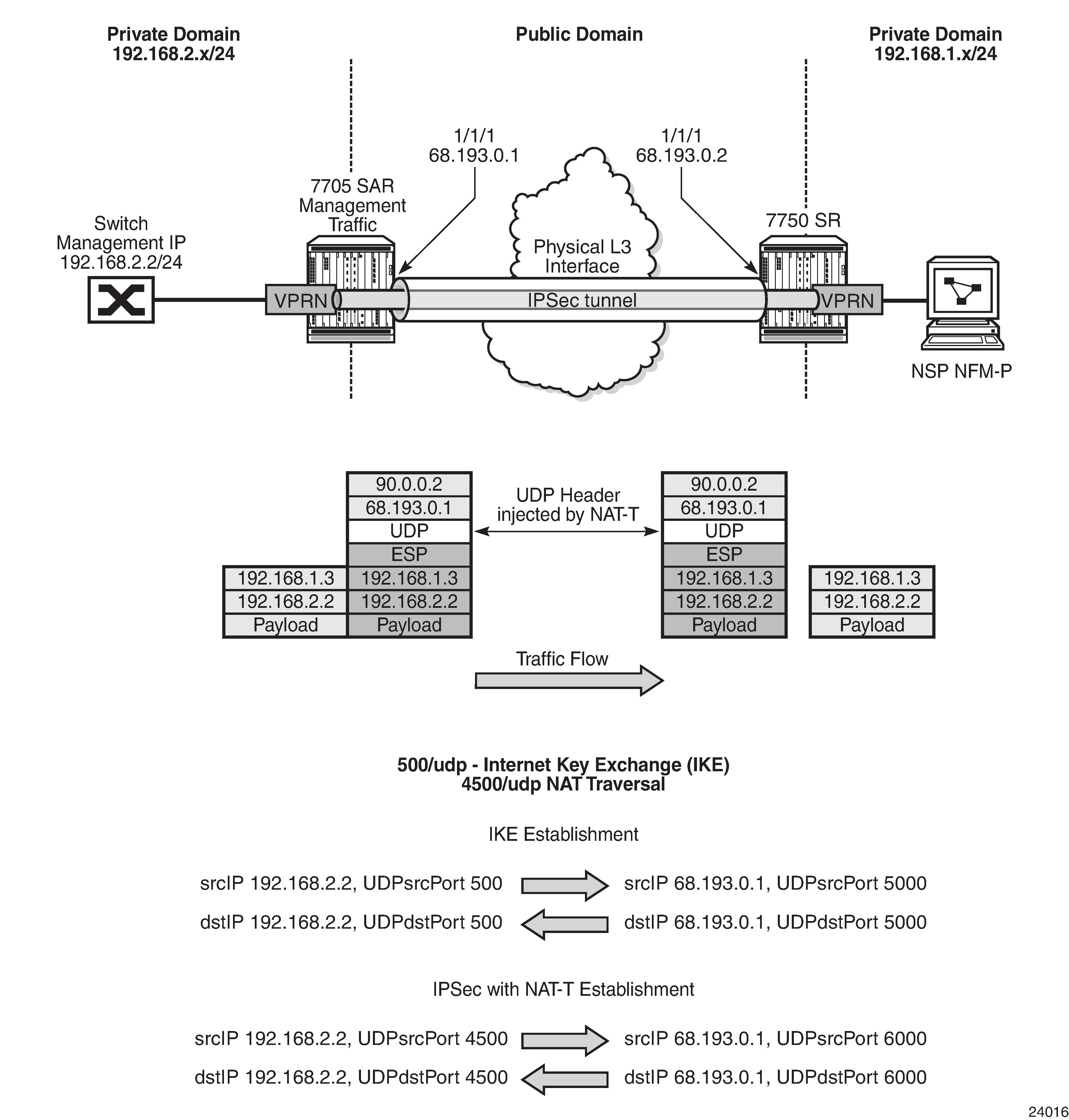
IPSec is an IP protocol and therefore does not use ports. UDP Header Injected by a NAT-T-enabled IPSec Tunnel illustrates how the UDP header is injected into the packet as well as the many-to-one to one-to-many mappings. NAT relies on port mapping, so in order to allow traversal of a NAT device, NAT-T adds a UDP header with port 4500 to the IPSec traffic when the NAT device is detected. The UDP header is added to the IPSec packet above the ESP header and IKEv1/v2 already uses UDP port 500. This UDP header can be used by the NAT device to uniquely map each IPSec tunnel and assign a different source port to each individual tunnel. That is, many IP addresses using UDP 4500 lead to a NAT mapping where a single public IP address uses many UDP ports.
In UDP Header Injected by a NAT-T-enabled IPSec Tunnel, the 7750 SR performs the following functions:
tracks the different metrocell IKEv2 port-to-session mappings
tracks the different metrocell IPSec port-to-tunnel mappings
transmits traffic to each metrocell on the appropriate UDP port
BFD over IPSec Tunnel
To configure BFD for an IPSec tunnel, do the following:
configure BFD on a loopback interface in the private VPRN
configure at least two IPSec tunnels:
one tunnel is a BFD-designate tunnel over which BFD packets are exchanged; this BFD-designate tunnel does not go down when BFD goes down
the other tunnels are tunnels that use the BFD-designate tunnel’s BFD session; these tunnels go down when BFD goes down
configure a static route in the private VPRN, where the static route points to the destination node’s private-side loopback interface, using the BFD-designate tunnel as the next hop
configure BFD under the BFD-designate tunnel using the loopback interface and point to the far-end loopback address
configure BFD under the protected tunnels also using the loopback interface (same configuration as under the BFD-designate tunnel)
QoS for IPSec
This section contains information on the following topics:
Network and Access Ingress QoS (Decryption QoS)
IPSec traffic arriving on network ingress is classified based on network policy and network queue policy when the uplink interface is a network interface (see the 7705 SAR Quality of Service Guide). This classification is done based on the DSCP marking of the IPSec outer IP header.
The IPSec (encrypted) traffic destined for the secure gateway (SeGW) of the 7705 SAR is mapped to two queues (expedited and best effort) of the decryption engine on the ingress adapter card. This means that encrypted traffic is mapped to the decryption queue.
The encrypted traffic is mapped to one of these two queues based on the queue-type of its mapped network ingress queue, as determined by the result of the network ingress classification. For example, at network ingress, the QoS network policy determines a forwarding class (FC) for the packet. Then, the network-ingress queue policy maps the FC to a queue. The configured queue-type of network-ingress queue (expedited, best-effort, or auto-expedite) is used to choose the queue for the decryption engine on the ingress adapter card (where the uplink interface resides).
The uplink interface for the SeGW can be configured as a network interface or as an access IES interface. For an access IES interface, the decryption-queue mapping is based on the queue-type of the access ingress queue of the IES interface SAP. For example, at IES ingress, the SAP ingress policy determines a forwarding class (FC) for the packet. The FC is mapped to a SAP ingress queue. The queue-type of this SAP ingress queue (expedited, best-effort, or auto-expedite) is used to choose the queue for the decryption engine on the ingress adapter card where the IES interface SAP resides.
The decrypted customer traffic with removed IPSec tunnel header is queued on network and access ingress queues (the uplink interface can be a network interface or an IES interface) based on the network and access ingress policy, and the DSCP bits of the IPSec outer IP header are used for the classification.
Network Ingress QoS Tunnel Override
When a network QoS policy is enabled on an ingress network interface, IPSec packets arriving at that interface are assigned to encryption queues based on the IPSec outer IP header. However, if the QoS network policy of the arriving network interface is configured with ler-use-dscp, then after decryption, all the datapath or firewall queuing is based on the DSCP marking of the IPSec inner IP header rather than on the DSCP marking of the IPSec outer IP header. For more information about the ler-use-dscp command, see the 7705 SAR Quality of Service Guide, ‟QoS Policy Network Commands”.
Network and Access Egress QoS (Encryption QoS)
Customer packets arriving on access ingress in the VPRN are classified based on the SAP ingress policy (see the 7705 SAR Quality of Service Guide).
Customer packets arriving in the VPRN that are destined for the IPSec tunnel are enqueued before the encryption engine on the egress adapter card. There are three queues servicing the encryption engine on the egress adapter card (expedited, best effort, and CTL).
All CSM traffic over IPSec (BFD, ping, and so on) is queued in the CTL queue, while data (customer) traffic is mapped to the expedited or best-effort queue.
The customer traffic to the two data queues is mapped based on the queue-type of the ingress SAP queue. For example, at access VPRN SAP ingress, the ingress SAP policy determines a forwarding class (FC) for the packet. The FC is mapped to a SAP ingress queue. The queue-type of the SAP ingress queue (expedited, best-effort, or auto-expedite) is used to choose the queue for the decryption engine on the egress adapter card (where the uplink interface resides).
Fragmentation and IP MTU
On the 7705 SAR, unencrypted IP packets arriving on a VPRN access interface and destined for an IPSec uplink will be fragmented if the incoming packet is larger than:
the VPRN private interface MTU
the IPSec tunnel MTU
the difference between the uplink MTU and the IPSec overhead (uplink interface MTU minus IPSec overhead), where the IPSec overhead values are calculated as follows:
IPSec overhead if NAT-T is enabled
IPSec overhead = outer IPSec (20) + UDP (8) + ESP (24) + trailer (17) + ICV (32) = 101 bytes
IPSec overhead if NAT-T is disabled (no nat-t)
IPSec overhead = outer IP (20) + ESP (24) + trailer (17) + ICV (32) = 93 bytes
For example, if a private tunnel interface has its IP MTU set to 1000 bytes, then a packet larger than 1000 bytes will be fragmented. As another example, if an uplink interface has its IP MTU set to 1000 bytes, then a packet that is larger than 1000 – IPSec overhead will be fragmented. Both these examples assume that the DF bit is not set or the clear-df-bit command is enabled.
Fragmentation Configuration
By default, the 7705 SAR sets the DF bit on the IPSec tunnel IP header.
There are some configurations where the customer IP header DF bit needs to be copied into the IPSec tunnel IP header. The copy-df-bit command under the config>service>vprn>if>sap>ipsec-tunnel context enables copying the customer clear text IP header DF bit into IPSec tunnel IP header.
The clear-df-bit command, also under the ipsec-tunnel context, clears the customer clear text IP header DF bit (if it is set). This allows the customer packet to be fragmented into the IPSec tunnel even if the customer packet has the DF bit set. However, the fragmented customer clear text packet is not be reassembled at the far end of IPSec tunnel.
Reassembly
The 7705 SAR does not support reassembly of fragmented IPSec packets.
Support for Private VPRN Service Features
Private VPRN access features are only supported on non-IPSec interfaces. That is, they are only supported for Layer 3 interfaces that are not configured with a private IPSec tunnel.
Some of the features supported include r-VPLS, VRRP and VRRPv3, ECMP, and LAG. See VPRN Services for information on these features.
Routing in Private Services
For static LAN-to-LAN tunnels, the static route with the IPSec tunnel as the next-hop could be exported to a routing protocol by a route policy. The protocol type remains static.
IPSec on the 10-port 1GigE/1-port 10GigE X-Adapter Card
The 10-port 1GigE/1-port 10GigE X-Adapter card has two encryption engines that share the encryption/decryption load. Therefore, the 10-port 1GigE/1-port 10GigE X-Adapter card has the potential for double the encryption/decryption throughput when compared with other adapter cards and nodes with a single encryption engine (the 8-port Gigabit Ethernet Adapter card, 7705 SAR-Ax, 7705 SAR-H, 7705 SAR-Hc, 7705 SAR-Wx, and 7705 SAR-X).
To utilize the potential of the 10-port 1GigE/1-port 10GigE X-Adapter card, the IPSec security associations (SAs) are load-balanced between the two engines based on a round-robin algorithm. When there is an SA download to the 10-port 1GigE/1-port 10GigE X-Adapter card, the upper-layer software load-balances the SA on the two engines.
IPSec Sequence Number
The IPSec sequence number is used to prevent replay attacks. A replay attack is a network attack in which valid data transmission is repeated or delayed for fraudulent purposes. The 7705 SAR supports a 32-bit sequence number, where the transmission of each packet increments the sequence number. If there is a sequence number rollover, the 7705 SAR performs the rollover by resignaling the phase-2 IKE negotiation.
PBR and MFC
Both PBR (policy-based routing) and MFC (multi-field classification) are part of the ingress ACL (access control list) configuration on the 7705 SAR. Hence, both PBR and MFC are supported by IPSec on the 7705 SAR, as discussed below:
PBR
PBR configuration can be applied in two places for an IPSec service.
The first place is for VPRN and applies to all incoming access traffic into a private VPRN. In this case, PBR can be used to direct the customer traffic into uplink IPSec tunnels by means of ACL matching criteria. The filtering action of forwarding to an indirect next hop can be used to direct customer traffic into the appropriate IPSec tunnel. The security policy works only on the original (customer packet) IP header; that is, the PBR next hop is not used in making the security policy decision.
The second place is for IPSec traffic entering the 7705 SAR from the public domain. A PBR filter can be placed on the network interface, the VPRN interface, or the IES interface to direct the IPSec packet based on the matching/forwarding criteria. In this case, IPSec packets are processed by the PBR filter in the same way as any other IP packet.
For more information about PBR, see the ‟Policy-Based Routing” section in the 7705 SAR Router Configuration Guide.
-
All routing decisions are made based on the PBR configuration; therefore, it is possible that even if the packet is destined for the local node security gateway (SeGW), the PBR filter may redirect the packet to another interface.
-
Alternatively, for IPSec packets that are not destined for the local node SeGW, PBR can force the packets into the local node SeGW. In this case, the encapsulating security payload (ESP) index of the IPSec packet does not match the SeGW ESP configuration and the packet is dropped. Thus, it is the responsibility of the network administrator to ensure that the PBR configuration is correct and meets the network needs.
MFC
Multi-field classification (MFC) is supported on the private IPSec service (VPRN). MFC functions in the same manner as the VPRN configuration of traditional services.
For more information about MFC, see the ‟Multi-field Classification” section in the 7705 SAR Router Configuration Guide.
OSPFv3 Packet Authentication with IPv6 IPSec
The 7705 SAR supports the use of IPv6 IPSec to authenticate OSPFv3 packets. The following features are supported:
two types of encryption and authentication protocols: authentication header (AH) and IP encapsulation security payload (ESP)
IPSec transport mode to authenticate the IP payload
manually keyed IPSec security associations (SA)
the MD5 and SHA1 authentication algorithms
In order to be authenticated, OSPFv3 peers must be configured with matching inbound and outbound SAs using the same parameters (for example, SPIs and encryption keys). One SA can be used for both inbound and outbound directions.
Authentication of OSPFv3 packets is supported on VPRN interfaces, network interfaces, and virtual links.
The 7705 SAR supports the rekeying procedure defined in RFC 4552, Authentication/Confidentiality for OSPFv3.
For every router on the link, create an additional inbound SA for the interface being rekeyed using a new SPI and the new key.
The SA replacement operation is atomic, meaning that no OSPFv3 packets are sent on the link until the replacement operation is complete. This ensures that no packets are sent without authentication or encryption.
For every router on the link, remove the original inbound SA.
The key rollover procedure automatically starts when the operator changes the configuration of the inbound static security association or bidirectional static security association under an interface or virtual link. Within the KeyRolloverInterval time period, OSPFv3 accepts packets with both the previous inbound static SA and the new inbound static SA; the previous outbound static SA continues to be used. When the timer expires, OSPFv3 only accepts packets with the new inbound static SA. For outgoing OSPFv3 packets, the new outbound static SA is used instead.
Network Security with IPv6 IPSec
A 7705 SAR system that supports encryption allows the use of IPv6 IPSec to provide network security over an IPv6 IPSec tunnel as defined in RFC 4301, Security Architecture for the Internet Protocol. An IPv6 IPSec tunnel is used to encrypt data from the access network to an endpoint.
Network security with IPv6 IPSec supports the following capabilities described in this guide:
all IPv6 and 6VPE access capabilities
static LAN-to-LAN
PSK
PKI
VLL over GRE over IPSec
static Security Association (SA) keying
IKEv2 dynamic keying (IKEv1 is not supported on IPv6 IPSec)
IKEv2 fragmentation as defined in RFC 7383, Internet Key Exchange Protocol Version 2 (IKEv2) Message Fragmentation
reassembly of IKE packets
node management of IPv6 and IPv4 traffic over an IPv6 IPSec tunnel using GRT leaking
dual-stack access interfaces
BGPv6 signaling and static route configuration to direct traffic to the IPv6 IPSec tunnel
BGPv6 support for IPv4 and IPv6 routes
IPv4 packet fragmentation
application of NAT and firewall security functions to IPv4 packets arriving on the private VPRN before the packets are routed to the IPv6 IPSec tunnel
Network security with IPv6 IPSec is also supported on a public VPRN and IES. On a public VPRN, the IPSec packets are treated as any other IP packets when 6VPE is configured on the VPRN. The 6VPE functionality is supported for IPSec packets over MPLS (MP-BGP) transport. The transport tunnels can be MPLS (SR, LDP/RSVP-TE) or GRE IPv4.
IPSec Over r-VPLS on a Public Service
A 7705 SAR system that supports encryption allows the forwarding of IPSec IPv4 and IPv6 packets over an r-VPLS next-hop interface on a VPRN service. The r-VPLS next-hop interface is resolved using whatever IGP the customer uses (such as RIP, OSPF, IS-IS, static routes, or BGP). The r-VPLS interface bound to a VPLS service can then transport the IPSec tunneled packets over Layer 2 VPN to a SAP or a spoke or mesh SDP.
Statistics
All statistics for security association and tunnel statistics on the 7705 SAR are retrieved from the datapath on demand. When the user requests the statistics for a tunnel, the statistics are retrieved directly from the datapath; the retrieved statistics are not cached on the 7705 SAR. This means that on redundant platforms (that is, on the 7705 SAR-8 Shelf V2 or 7705 SAR-18), statistics do not synchronize over to the inactive CSM and at the time of a CSM switchover, all statistics are lost. Also, in the case of statistics rollover in the datapath, the newly retrieved statistics start from 0 (zero) again.
Security Support
IPSec on the 7705 SAR requires a public service (IES or VPRN) and a private service (VPRN). All IPSec traffic on the public service is encrypted. By the time the traffic is routed to the private service, it has been decrypted. NAT can be applied to traffic traversing the IPSec public interface.
After being decrypted, the customer traffic may traverse a second security zone configured within the VPRN, to sanitize any of these packets according to the firewall rules. This security zone can be extended to have NAT performed on the customer clear text packets.
For more information about configuring security parameters, see the 7705 SAR Router Configuration Guide, ‟Configuring Security Parameters”.
Public Key Infrastructure (PKI)
Public Key Infrastructure (PKI) is a cryptographic technique that enables users to securely communicate on an insecure public network, and reliably verify and authenticate the identity of a user through the use of digital signatures.
PKI is a system for creating, storing, and distributing digital certificates, which are used to verify that a particular public key belongs to a particular entity. PKI creates digital certificates that map public keys to entities and securely stores these certificates in a central repository, revoking them as needed.
PKI includes the following components:
X.509v3 identity certificates
a certificate authority (CA), which has the following properties:
has a secure server
can sign and publish X.509v3 certificates
is trusted by all users of the system
public/private key pairs
the ability to be deployed as flat architecture or hierarchical architecture (chained certificates)
CA Role in PKI
The role of a CA in PKI includes the following items.
The CA is a trusted third-party organization or company that issues digital certificates.
The CA may or may not be a third party from the end entity’s (EE’s) point of view.
The CA often belongs to the same organization as the EEs it supports.
The CA can be a root CA or a subordinate CA:
root CA – a CA that is directly trusted by an end entity.
subordinate CA – CAs that are not root CAs. The first subordinate CA in a hierarchy obtains its CA certificate from the root CA. This first subordinate CA can, in turn, use this key to issue certificates that verify the integrity of another subordinate CA.
The CA verifies digital certificates using a chain of trust, the root CA being the trust anchor for the digital certificate.
The root CA issues a root certificate, which is the top-most certificate of the certificate tree. The root certificate’s private key is used to sign other certificates. All certificates immediately below the root certificate inherit the trustworthiness of the root certificate.
Digital Signature and Certificates
Digital signatures and digital certificates are not the same objects.
A digital signature is an electronic signature that can be used to demonstrate the authenticity of a message. Digital signatures use hashing and asymmetric encryption. There are two aspects to a digital signature:
signature construction
signature verification
A digital certificate is an electronic document that uses a digital signature to bind a public key with an identity that has been digitally signed by a CA.
Certificates
PKI uses two types of certificates:
root certificate
created by a well-known root CA (see CA Role in PKI)
used to validate the authenticity of provider certificates
must be installed on the 7705 SAR manually, where the installation method can be FTP, SFTP, or SC, into the cf3: directory of the 7705 SAR
provider certificate
created by each vendor for its own authentication needs
contains the public RSA or DSA keys that are used in PKI for the encryption of the phase 1 IKE message
must be signed by the root CA to prove the authenticity of the vendor certificate to the far-end node
Vendor Certificate Signature by the Root CA
For each vendor, the 7705 SAR must have a vendor certificate signed by the CA and stored internally.
The sequence of events is as follows:
The 7705 SAR creates an X.509v3 certificate and the key pair (public/private key).
The 7705 SAR sends the certificate to the CA to be signed by the CA private key.
The CA runs the hash over the X.509v3 certificate.
The result of the hash is encrypted via the CA public key (digital signature).
The digital signature is appended to the certificate and, consequently, the signed vendor certificate.
Vendor Certificate Authentication by a Peer
While the IKE is being initiated, phase 1 of the IKE can be authenticated via PKI. Therefore, the certificate from Vendor Certificate Signature by the Root CA is sent to the peer as part of the IKE authorization stage. The peer must ensure that this certificate is generated by the correct 7705 SAR and not an intermediary node.
Upon receiving the certificate, the peer does the following.
The peer runs a hash over the X.509v3 part of the certificate.
The peer decrypts the digital signature of the certificate.
If the hash calculated in step 1 and the hash decrypted in step 2 match, then the certificate is authenticated.
The peer can use the public key in the certificate to encrypt the IKE phase 2 channel.
Example of PKI Operation
In the following scenario, which provides an example of PKI operation, the 7705 SAR and 7750 SR trust the same CAs and they have already obtained the CA’s certificate (which includes the CA’s public key) using an out-band method. The CA issues a certificate for the 7705 SAR, as follows.
The CA calculates a hash of the contents of the 7705 SAR certificate, which includes the 7705 SAR public key, name, validity date, allowed uses for the certificate, and so on.
The CA encrypts this hash using its private key, and attaches the resulting signature to the 7705 SAR certificate.
The 7705 SAR can now present this signed certificate to the 7750 SR during the IKE phase.
The 7750 SR verifies the received certificate as follows.
The 7750 SR calculates its own hash of the 7705 SAR certificate contents.
The 7750 SR decrypts the signed hash in the certificate using the CA’s public key, and if the hashes match the 7750 SR knows that this certificate was signed by the CA.
Optionally, the 7750 SR consults the CA’s certificate revocation list (CRL) and checks that the certificate from the 7705 SAR has not been revoked.
Certificate Chain
A peer’s certificate may be issued by an intermediate CA. In this case, a user must have and trust all the intermediate CA certificates up to and including the root CA installed in the peer for authentication of an end entity.
The 7705 SAR supports the following implementation.
When receiving a certificate, all subordinate CAs must be installed locally (that is, only an EE certificate can be received from the peer and processed by the 7705 SAR). Even if a certificate chain is received from the peer, the 7705 SAR processes the EE certificate only.
The send-chain command under cert-profile is for third-party peers that support receiving a chain certificate. In this case, the 7705 SAR can send a chain certificate to be used in the entire chain if the third-party peer supports receiving a chained certificate. The 7705 SAR does not support receiving chained certificates.
Certificate Storage
The 7705 SAR IPSec configuration expects the keys and certificates to be stored in a particular directory on the 7705 SAR compact flash. This directory is called cf3:\system-pki and is created automatically when the first file is imported into this folder.
The following files can be imported and exported to and from the cf3:\system-pki directory. An example of the directory is shown after the list.
key pair – this file is encrypted during the import process
certificates
certificate revocation list (CRL)
A:ALU-A>file cf3:\system-pki\ # dir
Directory of cf3:\system-pki\
09/09/2015  09:17a     <DIR>        ./
09/09/2015  09:17a     <DIR>        ../
09/22/2015  11:38a              906 CMS1-ROOTCA-CERT
09/22/2015  11:41a              458 CMS1-ROOTCA-CRL
09/24/2015  08:18a              864 cert-1
09/25/2015  08:18a             1192 SAR-key-1
09/25/2015  09:32a              905 cal_cert_CMS1-SUBCA
09/25/2015  09:32a              457 cal_crl_CMS1-SUBCA
          6 Files(s)            4732 bytes.
          2 Dir(s)              65605632 bytes free.
CMPv2 Certificate Management
The Certificate Management Protocol (CMP) is an Internet protocol used for obtaining X.509v3 digital certificates in a PKI. It is described in RFC 4210. CMP messages are encoded in ASN.1 using the DER method and are usually transported over HTTP.
A CA issues the certificates and acts as the secure server in PKI using CMP. One of the clients obtains its digital certificates by means of this protocol and is called the end entity (EE).
The 7705 SAR supports the following CMPv2 operations:
initial registration (ir)
This is the process that the 7705 SAR uses to enroll a certificate with a certain CA for the first time.
A public/private key pair must be preprovisioned before enrollment by means of local generation or another method.
certificate update (cr)
This is the process whereby an initialized 7705 SAR obtains additional certificates.
key pair update (kur)
This is the process where the 7705 SAR updates an existing certificate due to any reason, such as a key or certificate refresh before the key or certificate expires.
polling
In some cases, the CA may not return the certificate immediately, for reasons such as ‟request processing needs manual intervention”. In such cases, the 7705 SAR supports polling requests and responses, as described in Section 5.3.22, Polling Request and Response, in RFC 4210.
CMPv2 Initial Registration
Initial registration is a process that the end entity uses to enroll a certificate with a certain CA for the first time. The result of this process is that a CA issues a certificate for an end entity’s public key, returning that certificate to the end entity or posting that certificate in a public repository (or both).
The 7705 SAR must be preprovisioned with the operator CA certificate.
The 7705 SAR public/private key pair is always preprovisioned before enrollment by means of local generation or another method.
The 7705 SAR uses the CMPv2 initial registration process to enroll its preprovisioned key with an operator’s CA. The result of this process is a certificate issued by the operator’s CA.
There are two authentication methods (PKI message protection) in this process, which are chosen using the CLI:
MSG_MAC_ALG: uses a pre-shared key and a reference number that is pre-issued by the CA
MSG_SIG_ALG: uses a CLI-provided protection key to sign the message; if a protection key is not provided, the key to be certified is used
Key Update
When a key pair is due to expire, the relevant end entity (EE) may request a key update. That is, the EE may request that the CA issue a new certificate for a new key pair or, under certain circumstances, a new certificate for the same key pair. The request is made using a key update request (kur) message, also known as a certificate update operation.
This command requests a new certificate from the CA in order to update an existing certificate due to reasons such as the need to refresh a key or to replace a compromised key.
If the EE already has a signing key pair with a corresponding verification certificate, then communication between the EE and the CA is protected by the EE’s digital signature.
If the request is successful, the CA returns the new certificate in a key update response (kup) message, which is syntactically identical to a CertRepMessage.
CRL
In the operation of some cryptosystems, such as PKIs, a certificate revocation list (CRL) is used. A CRL is list of certificates (or more specifically, a list of serial numbers for certificates) that have been revoked. Entities presenting those revoked certificates should not be trusted.
The CRL must be obtained and imported via CMPv2.
OCSP
The online certificate status protocol (OCSP) enables applications to determine the revocation status of an X.509v3 digital certificate. OCSP was created as an alternative to using CRLs and can be used to obtain additional status information. OCSP is described in RFC 6960.
Messages communicated via OCSP are encoded in ASN.1 and are usually communicated over HTTP. OCSP consists of a request message and a response message.
An OCSP responder may return a signed response indicating that the certificate specified in the request is good, revoked, or unknown. The Enterprise Java Bean Certificate Authority (EJBCA) server contains, by default, an internal OCSP responder and, therefore, can be used in conjunction with the 7705 SAR.
Ensure that both the 7705 SAR and the OCSP server are running NTP so that both devices are synchronized with respect to their timing.
Certificate or CRL Expiration Warning
The system can optionally generate a warning message before a certificate or a CRL expires. The amount of time before expiration is configurable with the certificate-expiration-warning and crl-expiration-warning commands. The warning messages can also be repeated at configured intervals.
If a configured EE certificate expires, the system does not bring down an established IPSec-tunnel; however, future certificate authentication fails.
If a CA certificate expires, the system brings the CA profile operationally down. This does not affect established tunnels; however, future certificate authentication that uses the CA profile fails.
Automatic CRL Update
With the automatic CRL update feature, the 7705 SAR can be scheduled to automatically connect to a list of configured HTTP URLs to download a new CRL file. If a CRL file is successfully downloaded and qualified, it replaces the existing CRL file. A CRL file is considered qualified if it is a valid CRL signed by the CA and is more recent than the existing CRL. To determine if a downloaded CRL is more recent than the existing CRL, the system first compares the This Update field of both CRL files, which indicates the issue date of the CRL. If the dates are the same, the system compares the CRL number extension, if present; a higher number indicates a more recent CRL.
This feature supports two types of CRL update schedules:
periodic — the system initiates a CRL update periodically, at the intervals specified by the periodic-update-interval command. For example, if the periodic update interval is 24 hours, the system will check the configured URLs for a new CRL file to download every 24 hours. The minimum periodic update interval is 1 hour.
next-update-based — the system initiates a CRL update at the date and time specified in the Next Update field of the existing CRL file, minus the time configured with the pre-update-time command. For example, if the existing CRL Next Update is 2022-06-30 06:00 and the pre-update time is 1 hour, the system begins the CRL update process at 2022-06-30, 05:00.
Up to eight URL entries can be configured under each CA profile. The configured URLs must point to a DER-encoded CRL file. When a CRL update is initiated, the system accesses each URL in order, and the first successfully downloaded and qualified CRL is used to update the existing CRL. If the download fails or the downloaded CRL is not qualified, the system moves to the next URL in the list. If no CRL can be downloaded or qualified, the system attempts to contact each URL again at the next scheduled update time (when the schedule type is periodic) or after the time configured with the retry-interval command (when the schedule type is next-update-based).
HTTP transport can be over IPv4 or IPv6. Automatic CRL update supports base, management, or VPRN routing instances. If VPRN is used, the HTTP server port can only be 80 or 8080.
A CRL update is initiated immediately if auto-crl-update is enabled and the system detects that the configured CRL file does not exist, or is invalid or expired, or if the schedule type is configured as next-update-based and the scheduled update time has already passed.
A CRL update can be initiated manually with the admin>certificate>crl-update command, but automatic CRL update must first be shut down.
Best Practices Recommendations
This section provides best practices recommendations.
IPSec Best Practices
To avoid high CPU loads and some complex cases, the following are suggestions to configure the IKEv2 lifetime.
Both the IKE_SA and CHILD_SA lifetime on one side should be approximately 2 or 3 times larger than the other side.
With the previous rule, the lifetime of the side with the smaller lifetime should NOT be too small:
IKE_SA: greater than or equal to 86 400 s
CHILD_SA: greater than or equal to 3600 s
With the first rule, on the side with the smaller lifetime, the IKE_SA lifetime should be at least 3 times larger than the CHILD_SA lifetime.
The IKE protocol is the control plane of IPSec; therefore, the IKE packet should be treated as high QoS priority in the end-to-end path of public service.
On a public interface, a SAP-ingress QoS policy should be configured to ensure that the IKE packet gets high QoS priority.
Configuration Notes
This section describes operational conditions and IPSec configuration guidelines and caveats.
A tunnel group that is in use cannot be deleted. Changes are allowed only when the tunnel group is in a shutdown state.
A change to the IPSec transform policy is allowed at any time. The change does not impact tunnels that have been established until they are renegotiated. If the change is required immediately, the tunnel must be cleared (reset) for force renegotiation.
A change to the IKE policy is allowed at any time. The change does not impact tunnels that have been established until they are renegotiated. If the change is required immediately, the tunnel must be cleared (reset) for force renegotiation.
An IPSec tunnel must be shut down before the transform policy can be modified.
The public interface address can be changed at any time (current behavior). If changed, tunnels that were configured to use it require a configuration change. If the subnet has been changed, the tunnels are in an operationally down state until their configuration is corrected. The public service cannot be deleted while tunnels are configured to use it. A public service is the IES or VPRN service that holds an interface with a public tunnel SAP that connects the node to the public network. A private service connects to the private protected service.
The 7705 SAR supports only one tunnel group (tunnel-group 1).
A change to the security policy is not allowed while a tunnel is active and using the policy.
The tunnel local gateway address, peer address, or delivery router parameters cannot be changed while the tunnel is operationally up (shutdown makes the tunnel both administratively down and operationally down).
A tunnel security policy cannot be changed while the tunnel is operationally up. An IPSec transform policy or IKE policy assignment to a tunnel requires the tunnel to be shut down.
Configuring IPSec with CLI
This section provides information to configure IPSec using the command line interface.
Topics in this section include:
Basic Configuration Overview
The following list provides a high-level outline for setting up IPSec on the 7705 SAR.
Create an IPSec tunnel group.
Configure an IPSec IKE policy.
Configure an IPSec transform policy.
Create a private-side tunnel interface on a VPRN service.
Create an interface using the tunnel keyword and private tunnel SAP.
Create the IPSec tunnel and configure its parameters, which include local and peer gateway IP addresses, IP MTU, keying (manual or dynamic), and so on.
Create a public-side tunnel interface on an IES or VPRN service.
Create an interface and public tunnel SAP.
Configure a VPRN static route for the IPSec tunnel.
Common Configuration Tasks
This section provides a brief overview of the following common configuration tasks that must be performed to configure IPSec:
Configuring an IPSec Tunnel Group
The following output displays an IPSec group configuration in the ISA context. The 7705 SAR supports only one tunnel-group. The tunnel-group-id is always 1.
*A:7705custDoc:Sar18>config>isa# info detail
----------------------------------------------
        tunnel-group 1 create
            shutdown
            no description
        exit
----------------------------------------------
*A:7705custDoc:Sar18>config>isa#
Configuring Router Interfaces for IPSec
An IPSec tunnel requires the following three interfaces:
public tunnel interface (under IES or VPRN)
private tunnel interface (under VPRN)
physical untrusted network/Internet-facing interface: IES, VPRN, or router
The physical interface is the one that must reside on an encryption-capable adapter card.
The following example displays an interface (‟internet”) configured using a network port (1/1/1) and an IES interface (‟public”) configuration using SAP 1/1/8.
*A:ALU-49>config>router# info
----------------------------------------------
...
    router
        interface "internet"
            address 10.10.7.118/11
            port 1/1/1
        exit
        interface "system"
            address 10.20.1.118/12
        exit
         autonomous-system 123
    exit
...
----------------------------------------------
*A:ALU-49>config>router#
*A:7705:Dut-A>config>service>ies# info
----------------------------------------------
            description "ies interface towards internet"
            interface "public" create
                address 10.1.1.1/1
                sap 1/1/8 create
                    description "sap-100-10.1.1.1"
                exit
            exit
            no shutdown
----------------------------------------------
Configuring IPSec Parameters
Under the IPSec context, configure the IKE policy and IPSec transform parameters.
The following example displays the IPSec parameter configuration output.
*A:7705custDoc:Sar18>config>ipsec# info
#--------------------------------------------------
    ipsec
        ike-policy 2 create
            ike-version 2
            own-auth-method psk
            dh-group 14
            ipsec-lifetime 48000
            isakmp-lifetime 60000
            pfs dh-group 5
            auth-algorithm sha384
            encryption-algorithm aes192
            nat-traversal keep-alive-interval 240
            no ikev2-fragment
            dpd interval 25
        exit
        ipsec-transform 2 create
            esp-auth-algorithm md5
            esp-encryption-algorithm 3des
        exit
    exit
#--------------------------------------------------
Configuring IPSec and IPSec Tunnels in Services
IPSec is configured under IES and VPRN services.
For the private-side IPSec tunnel interface and SAP, under the VPRN service context, configure IPSec security policies, and create tunnel interfaces, private tunnel SAPs, IPSec tunnels, and IPSec tunnel parameters. The tunnel keyword must be used when creating an interface for a private tunnel SAP.
For a public-side IPSec tunnel interface and SAP, under the IES or VPRN service context, create an interface and public tunnel SAP. The tunnel keyword is not used when creating an interface for a public tunnel SAP.
Private-side and public-side tunnels function in pairs, where a pair is defined by the service ID and the interface subnet.
The local gateway address and delivery service configured using the VPRN ipsec-tunnel>local-gateway-address command correspond to the IES or VPRN interface address and service ID where the public-side tunnel interface is defined. In the example below, the local-gateway-address is 10.10.10.11 and the delivery-service is 10.
The following example displays the configuration output when configuring IPSec for a private-side VPRN service and a public-side IES.
*A:7705custDoc:Sar18>config>service>vprn# info detail
----------------------------------------------
...
            ipsec
                security-policy 1 create
                    entry 1 create
                        local-ip any
                        remote-ip any
                    exit
                    entry 2 create
                        local-ip 198.51.100.0/24
                        remote-ip 198.51.100.0/24
                    exit
                exit
                security-policy 15 create
                    entry 15 create
                        no local-ip
                        no remote-ip
                    exit
                exit
            exit
...
            interface "vprn_tunnel" tunnel create
                no ip-mtu
                sap tunnel-1.private:22 create
                    no description
                    ingress
                        qos 1
                    exit
                    egress
                        qos 1
                        no filter
                        no agg-rate-limit
                    exit
                    ipsec-tunnel "ipsec_tunnel_tag1" create
                        shutdown
                        no description
                        security-policy 1 2
                        local-gateway address 10.10.10.11 peer 10.10.10.11
                           delivery-service 10
                        no bfd-designate
                        no clear-df-bit
                        no ip-mtu
                    exit
                    no shutdown
                exit
                no shutdown
            exit
            no service-name
            static-route-entry 192.100.200.10/32
                ipsec-tunnel "ipsec_tunnel_tag1"
                    no shutdown
                exit
            exit
----------------------------------------------
*A:7705custDoc:Sar18>config>service>vprn#
*A:7705custDoc:Sar18>config>service>ies# info detail
----------------------------------------------
  ...
        ies 10 customer 1 create
            interface "ies_tunnelPublicSide_1" create
                address 10.10.10.1/8
                sap tunnel-1.public:22 create
                    no description
                    ingress
                        qos 1
                    exit
                    egress
                        qos 1
                        no filter
                        no agg-rate-limit
                    exit
                    no collect-stats
                    no accounting-policy
                    no shutdown
                exit
            exit
            no service-name
----------------------------------------------
*A:7705custDoc:Sar18>config>service>ies#
Configuring IPSec IPv6 Parameters for a VPRN Private Service
Use the following CLI syntax to configure IPSec IPv6 parameters for a VPRN private service:
- CLI Syntax:
config>service# vprn service-id [customer customer-id] [create]ipsecsecurity-policy security-policy-id [create]entry entry-id [create]local-v6-ip {ipv6-prefix/prefix-length | any}remote-v6-ip {ipv6-prefix/prefix-length | any}
- Example:
A:ALU-41>config>service# vprn 1011A:ALU-41>config>service>vprn$ ipsecA:ALU-41>config>service>vprn>ipsec>security-policy$ 1 createA:ALU-41>config>service>vprn>ipsec>sec-plcy>entry$ 1 createA:ALU-41>config>service>vprn>ipsec>sec-plcy>entry>local-v6-ip$ 2001:db8:a::123/64A:ALU-41>config>service>vprn>ipsec>sec-plcy>entry>local-v6-ip$ exitA:ALU-41>config>service>vprn>ipsec>sec-plcy>entry>remote-v6-ip$ 2001:db8:a::222/64A:ALU-41>config>service>vprn>ipsec>sec-plcy>entry>remote-v6-ip$ exitA:ALU-41>config>service>vprn>ipsec>sec-plcy>entry$ exitA:ALU-41>config>service>vprn>ipsec>security-policy$ exitA:ALU-41>config>service>vprn>ipsec$ exit
The following example displays IPSec IPv6 parameters configuration output.
*A:7705:Dut-A>config>service>vprn# info
----------------------------------------------
            ipsec
                security-policy 1 create
                    entry 1 create
                        local-v6-ip 2001:db8:a::123/64
                        remote-v6-ip 2001:db8:a::222/64
                    exit
                exit
            exit
Configuring X.509v3 Certificate Parameters
Perform the following steps to configure certificate enrollment.
Generate a key:
admin certificate gen-keypair cf3:/key_plain_rsa2048 size 2048 type rsa
Generate a certificate request:
admin certificate gen-local-cert-req keypair cf3:/key_plain_rsa2048 subject-dn "C=US,ST=CA,CN=7705" file 7705_req.csr
Send the certificate request to CA-1 to sign and get the signed certificate.
Import the key:
admin certificate import type key input cf3:/key_plain_rsa2048 output key1_rsa2048 format der
Import the signed certificate:
admin certificate import type cert input cf3:/7705_cert.pem output 7705cert format pem
Perform the following steps to import the CA certificate and CRL.
Import the CA certificate:
admin certificate import type cert input cf3:/CA_1_cert.pem output ca_cert format pem
Import the CA’s CRL:
admin certificate import type crl input cf3:/CA_1_crl.pem output ca_crl format pem
The following example displays a certificate authentication for IKEv2 static LAN-to-LAN tunnel configuration.
config>system>security>pki# info
----------------------------------------------
                ca-profile "alu-root" create
                    cert-file "alu_root.cert"
                    crl-file "alu_root.crl"
                    no shutdown
                exit
----------------------------------------------
config>ipsec# info
----------------------------------------------
        ike-policy 1 create
            auth-method cert-auth
        exit
        ipsec-transform 1 create
        exit
       cert-profile "segw" create
            entry 1 create
                cert segw.cert
                key segw.key
            exit
            no shutdown
        exit
        trust-anchor-profile "alu" create
            trust-anchor "alu-root"
        exit

config>service>vprn>if>sap
----------------------------------------------
                ipsec-tunnel "t50" create
                    security-policy 1
                local-gateway-address 192.168.55.30 peer 192.168.33.100 delivery-
                                service 300
                    dynamic-keying
                        ike-policy 1
                        transform 1
                        cert
                            trust-anchor-profile "alu"
                            cert-profile "segw"
                        exit
                    exit
                    no shutdown
                exit
The following example displays the syntax to import a certificate from the PEM format.
*A:ALU-A# admin certificate import type cert input cf3:/pre-import/R1-
0cert.pem output R1-0cert.der format pem
The following example displays the syntax to export a certificate to the PEM format.
*A:ALU-A#  admin certificate export type cert input R1-0cert.der output cf3:/
R1-0cert.pem format pem
Configuring CMPv2
CMPv2 server information is configured under a corresponding ca-profile by using the following CLI commands:
- CLI Syntax:
-
config>system>security>pki>ca-profilecmpv2url url-string [service-id service-id]response-signing-cert filenamekey-listkey password [hash | hash2] reference reference-number
The url command specifies the HTTP URL of the CMPv2 server and the service-id specifies the routing instance that the system used to access the CMPv2 server (if the service ID is omitted, the system uses the base routing instance).
The service ID is only needed for in-band connections to the server via VPRN services. IES services are not referenced by the service ID, because an IES service routing instance is considered to be a base routing instance.
The response-signing-cert command specifies an imported certificate that is used to verify CMP response messages if they are protected by a signature. If this command is not configured, the CA’s certificate is used.
The key-list command specifies a list of pre-shared-keys used for CMPv2 initial registration message protection.
- Example:
-
config>system>security>pki>ca-profile>cmpv2url "http://cmp.example.com/request" service-id 100key-listkey passwordToBeUsed [hash | hash2] reference "1"
All CMPv2 operations are invoked by using the admin certificate cmpv2 command.
If there is no key-list defined under the cmpv2 configuration, the system defaults to the cmpv2 transaction that was input for the command line related to authenticating a message without a sender ID. If there is no sender ID in the response message and there is a key-list defined, the system chooses the lexicographical first entry only, and if that fails, there is a fail result for the transaction.
The system supports optional commands (such as always-set-sender-ir) to support inter-operation with CMPv2 servers. See IPSec Command Reference for details about syntax and usage.
Configuring OCSP
OCSP server information is configured under the corresponding ca-profile:
- CLI Syntax:
config>system>security>pki>ca-profile>ocspresponder-url url-stringservice service-id
The responder-url command specifies the HTTP URL of the OCSP responder. The service command specifies the routing instance that the system used to access the OCSP responder.
- Example:
config>system>security>pki>ca-profile>ocspresponder-url ‟http://ocsp.example.com/request”service 100
For a given IPSec tunnel, the user can configure a primary method, a secondary method, and a default result.
- CLI Syntax:
config>service>vprn>if>sap>ipsec-tun>certstatus-verifyprimary {ocsp | crl}secondary {ocsp | crl}default-result {revoked | good}
- Example:
config>service>vprn>if>sap>ipsec-tun>certstatus-verifyprimary ocspsecondary crl
Configuring IPSec over MPLS
On the 7705 SAR, IPSec routes to the secure gateway address can be resolved by using either a BGP 3107 label route or an IGP shortcut. When BGP learns IPv4 addressed as BGP 3107 label routes, BGP resolves the next hops for these routes with an LDP or RSVP-TE tunnel. These BGP routes create BGP tunnels that can be used to resolve an IPSec secure gateway address. When an IGP shortcut is enabled on the 7705 SAR by using the config>router>ospf>rsvp-shortcut command, OSPF installs an OSPF route in the RIB, with an RSVP-TE LSP as the next hop. If this OSPF route is determined as the overall best route, then the next hop is an RSVP-TE tunnel.
The IPSec implementation on the 7705 SAR is VPN-based. In order to configure IPSec, a private VPRN and a public IES or VPRN must both be configured; the encryption and decryption functions occur between these two services.
This section shows a configuration example of an IPSec route resolved by a BGP 3107 label route and a configuration example of an IPSec route resolved by an IGP shortcut.
IPSec over BGP 3107 Label Route
To route IPSec traffic using BGP 3107 label routes, the following components must be configured:
a static LAN-to-LAN tunnel for IPSec traffic
a policy option to advertise the IPSec gateway using BGP
BGP with a BGP 3107 label route configured
an LDP or RSVP-TE tunnel to resolve the BGP 3107 label route
IPSec over BGP 3107 Label Route shows a scenario where IPSec traffic is routed over a BGP 3107 label route. In this example, both the BGP 3107 tunnel and the IPSec tunnel are set up between Dut-A and Dut-F. The nature of BGP 3107 requires the LDP or RSVP-TE tunnel to be set up inside the autonomous system between Dut-A and Dut-E.
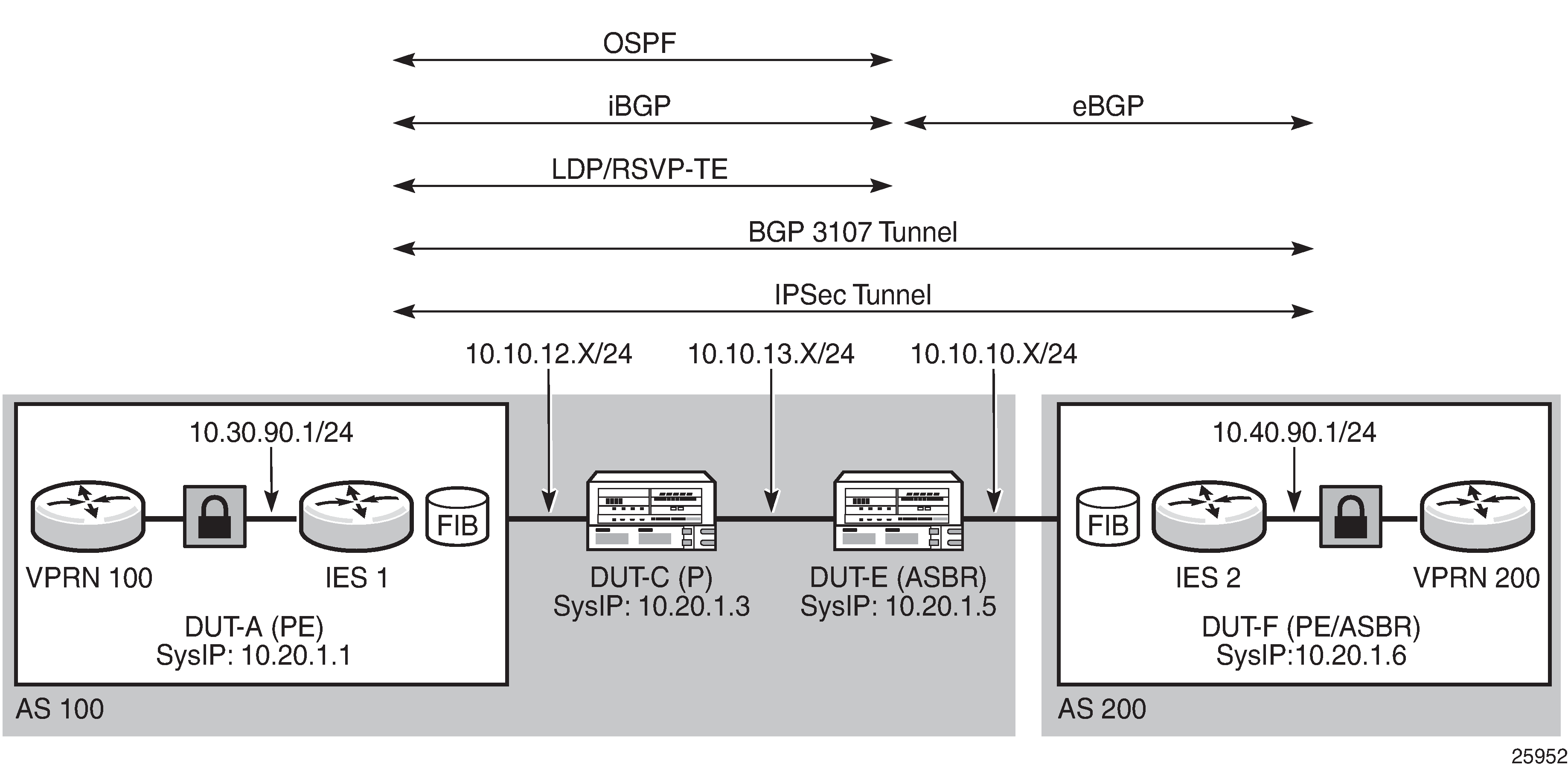
Static LAN-to-LAN Tunnel Configuration
Setting up a static LAN-to-LAN tunnel for IPSec traffic involves configuring a number of elements, including:
VPRN private-side service parameters, including the following:
BGP parameters
route distinguisher parameter
auto-bind-tunnel parameter or VPRN spoke SDP
VRF route-target associations or VRF import/export policies
OSPF parameters
a VPRN interface and its SAP parameters
spoke-SDP parameters on the VPRN interface
IES or VPRN public-side service parameters
IPSec parameters
The CLI output below is an example of a static LAN-to-LAN tunnel configuration.
*A:7705:Dut-A>config>service>vprn# info
----------------------------------------------
            description "Default Description For VPRN ID 90"
            snmp-community "Ku/I.yvsMoQ" hash2 version both
            ipsec
                security-policy 1 create
                    entry 1 create
                        local-ip any
                        remote-ip any
                    exit
                exit
            exit
            router-id 10.20.1.1
            autonomous-system 900
            route-distinguisher 10.20.1.1:90
            auto-bind-tunnel
                resolution-filter
                    ldp
                exit
                resolution filter
            exit
            vrf-target target:65000:90
            interface "ies-90-192.168.90.1" create
                address 192.168.90.1/24
                sap 1/2/1:900 create
                    description "sap-90-192.168.90.1"
                exit
            exit
            interface "ies-90-192.168.90.2" create
                address 192.168.90.2/24
                loopback
            exit
            interface "vprn-90-sap-tunnelPrivate-1" tunnel create
                sap tunnel-1.private:1 create
                    description "sap-90-IPSEC"
                    ipsec-tunnel "tunnelPrivateSide1" create
                        security-policy 1
                        local-gateway-address 10.30.90.1 peer 10.40.90.1 delivery-
service 9090
                        dynamic-keying
                            ike-policy 1
                            pre-shared-key "SmS3kjoVVF8ovXfOfxudQJ/
tw3MPVYZp1x1v2z2KkYJ5xY0hdURJyU" hash2
                            transform 1
                        exit
                        no shutdown
                    exit
                exit
            exit
            static-route-entry 10.1.1.1/8
                ipsec-tunnel "tunnelPrivateSide1"
                    no shutdown
                exit
            exit
            bgp
                min-route-advertisement 1
                import "BgpVpn_to_Bgp"
                export "BgpVpn_to_Bgp"
                router-id 10.20.1.1
                group "ce-peers"
                    neighbor 10.1.1.4
                        local-address 10.1.1.3
                        peer-as 90000
                    exit
                    neighbor 10.1.1.5
                        local-address 10.1.1.6
                        med-out 100
                        peer-as 9001
                    exit
                exit
                no shutdown
            exit
            service-name "XYZ Vprn 90"
            no shutdown
----------------------------------------------
*A:7705:Dut-A>config>service>vprn#
*A:7705:Dut-A>config>service>vprn# exit all
*A:7705:Dut-A# configure  service ies 9090
*A:7705:Dut-A>config>service>ies# info
----------------------------------------------
            description "Default Ies description for service id 9090"
            interface "tunnelPublicSide1" create
                address 10.30.90.3/8
                sap tunnel-1.public:1 create
                    description "sap-9090-10.30.90.3"
                exit
            exit
            service-name "XYZ Ies 9090"
            no shutdown
----------------------------------------------
*A:7705:Dut-A>config>service>ies#
Policy Option Configuration
The CLI output below is an example of a policy option configuration.
#--------------------------------------------------
*A:7705:Dut-A>config>router>policy-options# info
#--------------------------------------------------
            prefix-list "pe_sys_pref"
                prefix 10.30.90.0/8 longer
            exit
            policy-statement "pe_sys_to_bgp"
                entry 10
                    from
                        prefix-list "pe_sys_pref"
                    exit
                    to
                        protocol bgp
                    exit
                    action accept
                    exit
                exit
            exit
            commit
        exit
BGP Configuration with BGP 3107 Label Route Advertisement
The CLI output below is an example of BGP enabled with label route advertisement.
#--------------------------------------------------
*A:7705:Dut-A>config>router>bgp# info
#--------------------------------------------------
        bgp
            connect-retry 5
            keepalive 5
            hold-time 15
            min-route-advertisement 2
            transport-tunnel mpls
            group "to_asbr_Dut-E"
                description "Group to ASBR - vpn label v4"
                peer-as 100
                neighbor 10.20.1.5
                    family ipv4 vpn-ipv4 vpn-ipv6
                    export "pe_sys_to_bgp"
                    peer-as 100
                    advertise-label ipv4
                exit
            exit
            no shutdown
        exit
LDP or RSVP-TE Tunnel Configuration
The CLI output below is an example of an LDP tunnel that is configured to resolve the next hop for the BGP 3107 label route. An RSVP-TE tunnel could also be configured to resolve the next hop.
*A:7705:Dut-A>config>router# info
----------------------------------------------
#--------------------------------------------------
echo "IP Configuration"
#--------------------------------------------------
        interface "system"
            address 10.20.1.1/8
            no shutdown
        exit
        interface "to-P-Dut-C"
            address 10.10.12.1/8
            port 1/2/7:12
            no shutdown
        exit
        interface "to-P-Dut-D"
            address 10.10.3.1/8
            port 1/2/3:1
            no shutdown
        exit
        autonomous-system 100
#--------------------------------------------------
echo "OSPFv2 Configuration"
#--------------------------------------------------
        ospf
            traffic-engineering
            timers
                spf-wait 1000 1000 1000
            exit
            area 0.0.0.0
                interface "system"
                    hello-interval 5
                    dead-interval 15
                    metric 100
                    no shutdown
                exit
                interface "to-P-Dut-D"
                    interface-type broadcast
                    hello-interval 1
                    dead-interval 4
                    mtu 1518
                    metric 100
                    no shutdown
                exit
                interface "to-P-Dut-C"
                    interface-type broadcast
                    hello-interval 1
                    dead-interval 4
                    mtu 1518
                    metric 100
                    no shutdown
                exit
            exit
        exit
#--------------------------------------------------
echo "MPLS Configuration"
#--------------------------------------------------
        mpls
            interface "system"
                no shutdown
            exit
            interface "to-P-Dut-D"
                no shutdown
            exit
            interface "to-P-Dut-C"
                no shutdown
            exit
        exit
#--------------------------------------------------
echo "MPLS LSP Configuration"
#--------------------------------------------------
        mpls
            path "to-Dut-E"
                hop 1 10.20.1.3 strict
                no shutdown
            exit
            lsp "lsp-to-Dut-E"
                to 10.20.1.5
                cspf
                fast-reroute facility
                exit
                retry-timer 20
                primary "to-Dut-E"
                exit
                no shutdown
            exit
            no shutdown
        exit
#--------------------------------------------------
echo "LDP Configuration"
#--------------------------------------------------
        ldp
            interface-parameters
                interface "to-P-Dut-D"
                exit
                interface "to-P-Dut-C"
                exit
            exit
            targeted-session
            exit
            no shutdown
        exit
IPSec over IGP Shortcut
To route IPSec traffic over an IGP shortcut, the following must be configured:
a static LAN-to-LAN tunnel
an IGP shortcut (by creating an RSVP-TE tunnel in the OSPF context)
an RSVP-TE LSP to the system IP address or loopback address, with CSPF enabled
Static LAN-to-LAN Tunnel Configuration
The CLI output below is an example of a static LAN-to-LAN tunnel configuration.
#--------------------------------------------------
echo "IPsec Configuration"
#--------------------------------------------------
    ipsec
        ike-policy 1 create
            description "ikePolicy_1"
            own-auth-method psk
            dh-group 1
            auth-algorithm md5
            dpd interval 10 max-retries 2
        exit
        ipsec-transform 1 create
            esp-auth-algorithm sha512
            esp-encryption-algorithm aes256
        exit
    exit
#--------------------------------------------------
echo "Service Configuration"
#--------------------------------------------------
    service
        customer 1 create
            description "Default customer"
        exit
        ies 101 customer 1 create
            interface "tunnelPublicSide_1" create
            exit
        exit
        vprn 1001 customer 1 create
            interface "tunnelPrivateSide_1" tunnel create
            exit
            interface "toIxia_1" create
            exit
        exit
        ies 101 customer 1 create
            description "Default Ies description for service id 101"
            interface "tunnelPublicSide_1" create
                address 10.1.254.1/8
                sap tunnel-1.public:1 create
                    description "sap-10-10.1.254.1"
                exit
            exit
            service-name "XYZ Ies 101"
            no shutdown
        exit
        vprn 1001 customer 1 create
            description "Default Description For VPRN ID 1001"
            ipsec
                security-policy 1 create
                    entry 1 create
                        local-ip 10.10.10.0/8
                        remote-ip 10.1.1.0/8
                    exit
                exit
            exit
            route-distinguisher 1.1.1.1:1001
            interface "tunnelPrivateSide_1" tunnel create
                sap tunnel-1.private:1 create
                    description "sap-1001-IPSEC"
                    ipsec-tunnel "tunnelPrivateSide_1.1" create
                        security-policy 1
                        local-gateway-address 10.1.1.1 peer 10.2.2.2 delivery-
service 101
                        dynamic-keying
                            ike-policy 1
                            pre-shared-
key ".7ZAfd0optpg.FzYqTSVYbfFgzc.GZYw7W98X2uDhnHy/VmhkWqkP." hash2
                            auto-establish
                            transform 1
                        exit
                        no shutdown
                    exit
                exit
            exit
            interface "toIxia_1" create
                address 10.254.254.1/8
                sap 1/2/1:101 create
                exit
            exit
            static-route-entry 10.1.1.0/8
                ipsec-tunnel "tunnelPrivateSide_1.1"
                    no shutdown
                exit
            exit
            service-name "XYZ Vprn 1001"
            no shutdown
        exit
    exit
#--------------------------------------------------
echo "OSPFv2 Configuration"
#--------------------------------------------------
        ospf
            area 0.0.0.0
                interface "tunnelPublicSide_1"
                    hello-interval 5
                    dead-interval 15
                    no shutdown
                exit
            exit
        exit
#--------------------------------------------------
IGP Shortcut Configuration
The CLI output below is an example of an IGP shortcut configuration. An IGP shortcut is created using the rsvp-shortcut command in the ospf context.
#--------------------------------------------------
echo "OSPFv2 Configuration"
#--------------------------------------------------
        ospf
            traffic-engineering
            timers
                spf-wait 1000 1000 1000
            exit
            rsvp-shortcut
            area 0.0.0.0
                interface "system"
                    hello-interval 5
                    dead-interval 15
                    no shutdown
                exit
                interface "network"
                    hello-interval 5
                    dead-interval 15
                    metric 100
                    no shutdown
                exit
            exit
        exit
#--------------------------------------------------
RSVP-TE LSP Configuration
The CLI output below is an example of an RSVP-TE LSP with CSPF enabled.
#--------------------------------------------------
echo "MPLS Configuration"
#--------------------------------------------------
        mpls
            interface "system"
                no shutdown
            exit
            interface "network"
                no shutdown
            exit
        exit
#--------------------------------------------------
echo "RSVP Configuration"
#--------------------------------------------------
        rsvp
            interface "system"
                no shutdown
            exit
            interface "network"
                no shutdown
            exit
            no shutdown
        exit
#--------------------------------------------------
echo "MPLS LSP Configuration"
#--------------------------------------------------
        mpls
            path "Path1AToC"
                no shutdown
            exit
            lsp "Lsp1AToC"
                to 10.10.20.1
                cspf
                retry-timer 20
                metric 100
                primary "Path1AToC"
                exit
                no shutdown
            exit
            no shutdown
        exit
    exit
#--------------------------------------------------
Service Management Tasks
This section provides a brief overview of the following service management tasks:
Deleting an IPSec IKE Policy or an IPSec Transform
An IPSec IKE policy or transform cannot be deleted if it is being used by an IPSec tunnel. To delete an IKE policy or IPSec transform:
- CLI Syntax:
config>service>vprn>if>sap>ipsec-tunnel# dynamic-keyingconfig>service>vprn>if>sap>ipsec-tunnel>dynamic-keying# no ike-policyconfig>service>vprn>if>sap>ipsec-tunnel>dynamic-keying# no transformconfig>service>vprn>if>sap>ipsec-tunnel>dynamic-keying# exit allconfig>ipsec# no ike-policy ike-policy-idconfig>ipsec# no ipsec-transform transform-id
- Example:
config>service>vprn>if>sap>ipsec-tunnel# dynamic-keyingconfig>service>vprn>if>sap>ipsec-tunnel>dynamic-keying# no ike-policyconfig>service>vprn>if>sap>ipsec-tunnel>dynamic-keying# no transformconfig>service>vprn>if>sap>ipsec-tunnel>dynamic-keying# exit allconfig>ipsec# no ike-policy 2config>ipsec# no ipsec-transform 2
Deleting a Public-Side IPSec Tunnel SAP and Interface
A public-side IPSec tunnel interface and SAP are created under an IES or VPRN service. The output below uses the CLI syntax and an example from the IES context to show how to delete a public-side IPSec tunnel interface and SAP:
- CLI Syntax:
-
config>service>ies>interface# no sap tunnel-id.public:tagconfig>service>ies# no interface ip-int-name
- Example:
-
config>service>ies>interface# no sap tunnel-1.public:22config>service>ies# no interface ies_tunnelPublicSide_1
Deleting a Private-Side IPSec Tunnel SAP and Interface
A private-side IPSec tunnel interface and SAP are created under a VPRN service. To delete a private-side IPSec tunnel interface and SAP:
- CLI Syntax:
config>service>vprn>interface# no sap tunnel-id.private:tagconfig>service>vprn# no interface ip-int-name
- Example:
config>service>vprn>interface# no sap tunnel-1.private:22config>service>vprn# no interface vprn-tunnel
Deleting an IPSec Security Policy
Security policies are created under the VPRN service. To delete an IPSec security policy:
- CLI Syntax:
config>service>vprn>ipsec# no security-policy security-policy-id
- Example:
config>service>vprn# no security-policy 35
Deleting an IPSec Tunnel
IPSec tunnels are created under the VPRN service. Although an IPSec tunnel is created on the private side of the tunnel in the CLI, the configuration itself is general and can apply to either the public or private side of the tunnel. To delete an IPSec tunnel:
- CLI Syntax:
config>service>vprn>if>sap# no ipsec-tunnel ipsec-tunnel-name
- Example:
config>service>vprn>if>sap# no ipsec-tunnel ies_tunnelPublicSide_1
IPSec Command Reference
Command Hierarchies
IPSec Configuration Commands
ISA Tunnel Commands
config
    - [no] isa
        - tunnel-group tunnel-group-id [create]
        - no tunnel-group tunnel-group-id
            - description description-string
            - no description
            - [no] shutdown
IPSec Commands
config
    - ipsec
        - ike-policy ike-policy-id [create]
        - no ike-policy ike-policy-id
            - auth-algorithm {md5 | sha1 | sha256 | sha384 | sha512 | auth-encryption}
            - no auth-algorithm
            - auth-method psk
            - no auth-method
            - description description-string
            - no description
            - dh-group {1 | 2 | 5 | 14 | 15}
            - no dh-group
            - dpd [interval interval] [max-retries max-retries] [reply-only]
            - no dpd
            - encryption-algorithm {des | 3des | aes128 | aes192 | aes256 | aes128-gcm8 | aes128-gcm16 | aes256-gcm8 | aes256-gcm16}
            - no encryption-algorithm
            - ike-mode {main | aggressive}
            - no ike-mode
            - ike-version {1 | 2}
            - no ike-version
            - ikev2-fragment mtu octets reassembly-timeout seconds
            - no ikev2-fragment
            - ipsec-lifetime ipsec-lifetime
            - no ipsec-lifetime
            - isakmp-lifetime isakmp-lifetime
            - no isakmp-lifetime
            - [no] match-peer-id-to-cert
            - nat-traversal [force] [keep-alive-interval keep-alive-interval] [force-keep-alive]
            - no nat-traversal
            - own-auth-method psk
            - no own-auth-method
            - pfs [dh-group {1 | 2 | 5}]
            - no pfs
            - prf-algorithm {md5 | sha1 | sha256 | sha384 | sha512 | aes-xcbc | same-as-auth}
            - no prf-algorithm
        - ipsec-transform transform-id [create]
        - no ipsec-transform transform-id
            - esp-auth-algorithm {null | md5 | sha1 | sha256 | sha384 | sha512 | auth-encryption}
            - no esp-auth-algorithm
            - esp-encryption-algorithm {null | des | 3des | aes128 | aes192 | aes256 | aes128-gcm8 | aes128-gcm12 | aes128-gcm16 | aes192-gcm8 | aes192-gcm12 | aes192-gcm16 | aes256-gcm8 | aes256-gcm12 | aes256-gcm16}
            - no esp-encryption-algorithm
        - static-sa sa-name [create]
        - no static-sa sa-name
            - authentication auth-algorithm ascii-key ascii-string
            - authentication auth-algorithm hex-key hex-string [hash | hash2]
            - no authentication
            - direction ipsec-direction
            - no direction
            - protocol ipsec-protocol
            - no protocol
            - spi spi
            - no spi
Service Configuration Commands
config
    - service
        - vprn service-id
            - ipsec
                - security-policy security-policy-id [create]
                - no security-policy security-policy-id
                    - entry entry-id [create]
                    - no entry entry-id
                        - local-ip {ip-prefix/prefix-length | ip-prefix netmask | any}
                        - no local-ip
                        - local-v6-ip {ipv6-prefix/prefix-length | any}
                        - no local-v6-ip
                        - remote-ip {ip-prefix/prefix-length | ip-prefix netmask | any}
                        - no remote-ip
                        - remote-v6-ip {ipv6-prefix/prefix-length | any}
                        - no remote-v6-ip
Service Interface Tunnel Commands
config
    - service
        - ies
            - interface ip-int-name [tunnel] [create]
            - no interface ip-int-name
                - sap sap-id [create]
                - no sap sap-id
config
    - service
        - vprn
            - interface ip-int-name [tunnel] [create]
            - no interface ip-int-name
                - sap sap-id [create]
                - no sap sap-id
                    - ipsec-tunnel ipsec-tunnel-name [create]
                    - no ipsec-tunnel ipsec-tunnel-name
                        - [no] bfd-designate
                        - bfd-enable service service-id interface interface-name dst-ip b ip-address
                        - no bfd-enable
                        - [no] clear-df-bit
                        - [no] copy-df-bit
                        - description description-string
                        - no description
                        - [no] dynamic-keying
                            - [no] auto-establish
                            - cert
                                - cert-profile profile
                                - no cert-profile
                                - remote-id type {ipv4 | ipv6 | fqdn | email} value value
                                - no remote-id
                                - status-verify
                                    - default-result {revoked | good}
                                    - no default-result
                                    - primary {crl | ocsp}
                                    - no primary
                                    - secondary {crl | ocsp}
                                    - no secondary
                                - trust-anchor-profile profile-name
                                - no trust-anchor-profile
                            - ike-policy ike-policy-id
                            - no ike-policy
                            - local-id type {ipv4 | fqdn | ipv6} value value
                            - no local-id
                            - pre-shared-key key [hash | hash2]
                            - no pre-shared-key
                            - transform transform-id [transform-id...(up to 4 max) ]
                            - no transform
                        - ip-mtu octets
                        - no ip-mtu
                        - local-gateway-address ip-address peer ip-address delivery-service service-id
                        - no local-gateway-address
                        - [no] manual-keying
                            - security-association security-entry-id authentication-key authentication-key encryption-key encryption-key spi spi transform transform-id direction {inbound | outbound}
                            - no security-association security-entry-id direction {inbound | outbound}
                        - security-policy security-policy-id
                        - no security-policy
Service Static Route Commands
config
    - service
        - vprn service-id
            - [no] static-route-entry ip-prefix/prefix-length
                - [no] ipsec-tunnel ipsec-tunnel-name
                    - [no] description description-string
                    - [no] metric metric
                    - [no] preference preference
                    - [no] shutdown
                    - [no] tag tag
See VPRN Service Configuration Commands for the command descriptions.
PKI Configuration Commands
X.509 and Certificate Commands
admin
    - certificate
        - clear-ocsp-cache [entry-id]
        - cmpv2
            - cert-request ca ca-profile-name current-key key-filename current-cert cert-filename [hash-alg hash-algorithm] newkey key-filename subject-dn subject-dn save-as save-path-of-result-cert
            - clear-request ca ca-profile-name
            - initial-registration ca ca-profile-name key-to-certify key-filename protection-alg {password password reference ref-number | signature [cert cert-file-name [send-chain [with-ca ca-profile-name]]] [protection-key key-filename] [hash-alg {md5 | sha1 | sha224 | sha256 | sha384 | sha512}]} subject-dn dn save-as save-path-of-result-cert
            - key-update ca ca-profile-name newkey key-filename oldkey key-filename oldcert cert-filename [hash-alg hash-algorithm] save-as save-path-of-result-cert
            - poll ca ca-profile-name
            - show-request [ca ca-profile-name]
        - display type {cert | key | crl | cert-request} url-string format {pkcs10 | pkcs12 | pkcs7-der | pkcs7-pem | pem | der} [password password]
        - export type {cert | key |crl} input input-filename output url-string format output-format [password password] [pkey pkey-filename]
        - gen-keypair url-string [size {512 | 1024 | 2048}] [type {rsa | dsa}]
        - gen-local-cert-req keypair url-string subject-dn subject-dn [domain-name domain-name] [ip-addr {ip-address | ipv6-address}] file url-string [hash-alg hash-algorithm] [use-printable]
        - import type {cert | key | crl} input url-string output filename format input-format [password password]
        - reload type {cert | key} filename [key-file filename]
PKI Infrastructure Commands
config
    - system
        - security
            - pki
                - ca-profile name [create]
                - no ca-profile name
                    - cert-file filename
                    - no cert-file
                    - cmpv2
                        - [no] accept-unprotected-errormsg
                        - [no] accept-unprotected-pkiconf
                        - [no] always-set-sender-for-ir
                        - http-response-timeout timeout
                        - no http-response-timeout
                        - http-version {1.0 | 1.1}
                        - key-list
                            - key password [hash | hash2] reference reference-number
                            - no key reference reference-number
                        - response-signing-cert filename
                        - no response-signing-cert
                        - [no] same-recipnonce-for-pollreq
                        - url url-string [service-id service-id]
                        - no url
                    - crl-file filename
                    - no crl-file
                    - description description-string
                    - no description
                    - ocsp
                        - responder-url url-string
                        - no responder-url
                        - service service-id
                        - no service
                    - revocation-check {crl | crl-optional}
                    - [no] shutdown
                - certificate-display-format {ascii | utf8}
                - certificate-expiration-warning hours [repeat repeat-hours]
                - no certificate-expiration-warning
                - crl-expiration-warning hours [repeat repeat-hours]
                - no crl-expiration-warning
                - maximum-cert-chain-depth level
                - no maximum-cert-chain-depth
IPSec PKI Commands
config
    - ipsec
        - cert-profile profile-name [create]
        - no cert-profile profile-name
            - entry entry-id [create]
            - no entry entry-id
                - cert cert-filename
                - no cert
                - key key-filename
                - no key
                - [no] send-chain
                    - [no] ca-profile name
        - ike-policy ike-policy-id [create]
        - no ike-policy ike-policy-id
            - auth-method {psk | cert-auth}
            - no auth-method
            - own-auth-method {psk |cert}
            - no auth-method
        - [no] shutdown
        - trust-anchor-profile name [create]
        - no trust-anchor-profile name
Automatic CRL Update Commands
admin
    - certificate
        - crl-update ca ca-profile-name
config
    - system
        - file-transmission-profile name [create]
        - no file-transmission-profile name
            - ipv4-source-address ip-address
            - no ipv4-source-address
            - ipv6-source-address ipv6-address
            - no ipv6-source-address
            - redirection level
            - no redirection
            - retry count
            - no retry
            - router router-instance
            - router service vprn-service-name
            - timeout seconds
        - security
            - pki
                - ca-profile name [create]
                - no ca-profile name
                    - auto-crl-update [create]
                    - no auto-crl-update
                        - crl-urls
                            - url-entry entry-id [create]
                            - no url-entry entry-id
                                - file-transmission-profile profile-name
                                - no file-transmission-profile
                                - url url
                                - no url
                        - periodic-update-interval [days days] [hrs hours] [min minutes] [sec seconds]
                        - pre-update-time [days days] [hrs hours] [min minutes] [sec seconds]
                        - retry-interval seconds
                        - no retry-interval
                        - schedule-type schedule-type
                        - [no] shutdown
Show Commands
show
    - certificate
        - ca-profile name [association]
        - ocsp-cache entry-id
        - statistics
    - ipsec
        - cert-profile name association
        - cert-profile [name]
        - cert-profile name entry [1..8]
        - ike-policy ike-policy-id
        - ike-policy
        - security-policy service service-id [security-policy-id security-policy-id]
        - security-policy
        - transform [transform-id]
        - trust-anchor-profile trust-anchor-profile association
        - trust-anchor-profile [trust-anchor-profile]
        - tunnel
        - tunnel ipsec-tunnel-name
        - tunnel count
show
    - mda slot/mda
        - statistics {source-mda | dest-mda | security [encryption]}      (for 7705 SAR-8 Shelf V2 and 7705 SAR-18)
    - mda aggregate-statistics       (for 7705 SAR-Ax, 7705 SAR-H, 7705 SAR-Hc, and 7705 SAR-Wx)
See the section ‟Show, Monitor, Clear, and Debug Command Reference” in the 7705 SAR Interface Configuration Guide for information about the show>mda commands.
show
    - router
        - interface ip-int-name statistics
See the section ‟IP Router Command Reference” in the 7705 SAR Router Configuration Guide for information about the show>router >interface statistics command.
Clear Commands
Debug Commands
debug
    - [no] cmpv2
        - [no] ca-profile profile-name
    - ipsec
        - [no] certificate filename
        - tunnel [ipsec-tunnel-name] [detail]
        - no tunnel [ipsec-tunnel-name]
Command Descriptions
IPSec Configuration Commands
Generic Commands
description
Syntax
description description-string
no description
Context
config>ipsec>ike-policy
config>isa>tunnel-group
config>service>ies>interface
config>service>ies>if>sap
config>service>vprn>interface
config>service>vprn>if>sap
config>service>vprn>if>sap>ipsec-tunnel
Description
This command creates a text description stored in the configuration file for a configuration context.
The no form of this command removes the string from the context.
Default
No description is associated with the configuration context.
Parameters
- description-string
the description character string. Allowed values are any string up to 80 characters long composed of printable, 7-bit ASCII characters. If the string contains special characters (such as #, $, or spaces), the entire string must be enclosed within double quotes.
shutdown
Syntax
[no] shutdown
Context
config>isa>tunnel-group
config>service>ies>interface
config>service>ies>if>sap
config>service>vprn>interface
config>service>vprn>if>sap
Description
The shutdown command administratively disables an entity. The operational state of the entity is disabled as well as the operational state of any entities contained within. When disabled, an entity does not change, reset, or remove any configuration settings or statistics. Many objects must be shut down before they may be deleted. Many entities must be explicitly enabled using the no shutdown command.
The no form of this command places the entity into an administratively enabled state.
Services are created in the administratively down state (shutdown). When a no shutdown command is entered, the service becomes administratively up and then tries to enter the operationally up state.
ISA Tunnel Commands
isa
Syntax
[no] isa
Context
config
Description
This command creates an ISA tunnel configuration context.
The no form of this command removes the context.
Default
n/a
tunnel-group
Syntax
tunnel-group tunnel-group-id [create]
no tunnel-group tunnel-group-id
Context
config>isa
Description
This command enables a tunnel group to be created or edited. The 7705 SAR can have only one tunnel group (tunnel-group 1).
The no form of the command deletes the specified tunnel group from the configuration.
Default
n/a
Parameters
- tunnel-group-id
specifies an integer value that uniquely identifies the tunnel group
- create
mandatory keyword required when creating a tunnel group. The create keyword requirement can be enabled/disabled in the environment>create context.
Internet Key Exchange (IKE) and Transform Commands
ipsec
Syntax
ipsec
Context
config
Description
This command enables the context to configure Internet Protocol security (IPSec) parameters. IPSec is a structure of open standards to ensure private, secure communications over Internet Protocol (IP) networks by using cryptographic security services.
ike-policy
Syntax
ike-policy ike-policy-id [create]
no ike-policy ike-policy-id
Context
config>ipsec
Description
This command enables provisioning of IKE policy parameters.
The no form of the command removes the IKE policy.
Parameters
- ike-policy-id
specifies a policy ID value to identify the IKE policy
- create
mandatory keyword required when creating an IKE policy. The create keyword requirement can be enabled/disabled in the environment>create context.
auth-algorithm
Syntax
auth-algorithm {md5 | sha1 | sha256 | sha384 | sha512 | auth-encryption}
no auth-algorithm
Context
config>ipsec>ike-policy
Description
This command specifies which hashing algorithm to use for the IKE authentication function.
The auth-encryption option must be specified when the encryption algorithm configured for the IKE session is an AES-GCM algorithm.
The no form of the command returns the parameter to its default value.
Default
sha1
Parameters
- md5
specifies the HMAC-MD5 algorithm for authentication
- sha1
specifies the HMAC-SHA1 algorithm for authentication
- sha256
specifies the HMAC-SHA256 algorithm for authentication
- sha384
specifies the HMAC-SHA384 algorithm for authentication
- sha512
specifies the HMAC-SHA512 algorithm for authentication
- auth-encryption
specifies an AES-GCM encryption algorithm for authentication
auth-method
Syntax
auth-method psk
no auth-method
Context
config>ipsec>ike-policy
Description
This command specifies the authentication method used with this IKE policy. Configuring the policy for pre-shared key (PSK) or no auth-method produces the same result because PSK is both the default value and the only option.
The no form of the command returns the parameter to its default value (psk).
Default
no auth-method
Parameters
- psk
both the client and the gateway authenticate each other by a hash derived from a secret PSK. Both client and gateway must have the PSK. This works with both IKEv1 and IKEv2.
dh-group
Syntax
dh-group {1 | 2 | 5 | 14 | 15}
no dh-group
Context
config>ipsec>ike-policy
Description
This command specifies which Diffie-Hellman group is used to calculate session keys:
Group1: 768 bits
Group2: 1024 bits
Group5: 1536 bits
Group14: 2048 bits
Group15: 3072 bits
More bits provide a higher level of security but require more processing.
The no form of the command returns the parameter to its default value (Group2).
Default
no dh-group (Group2)
dpd
Syntax
dpd [interval interval] [max-retries max-retries] [reply-only]
no dpd
Context
config>ipsec>ike-policy
Description
This command controls the dead peer detection (DPD) mechanism to detect a dead IKE peer.
The no form of the command disables DPD and returns the parameters to their default values.
Default
no dpd
Parameters
- interval
specifies the interval that is used to test connectivity to the tunnel peer. If the peer initiates the connectivity check before the interval timer, it is reset.
- max-retries
specifies the maximum number of retries before the tunnel is removed
- reply-only
specifies to only reply to DPD keepalives. Issuing the command without the reply-only keyword disables the reply-only behavior.
encryption-algorithm
Syntax
encryption-algorithm {des | 3des | aes128 | aes192 | aes256 | aes128-gcm8 | aes128-gcm16 | aes256-gcm8 | aes256-gcm16}
no encryption-algorithm
Context
config>ipsec>ike-policy
Description
This command specifies the encryption algorithm to use for the IKE session.
When AES-GCM is configured as the encryption algorithm for an IKE policy:
auth-algorithm must be set to auth-encryption
manual keying is not possible
The no form of the command returns the algorithm to its default value.
Default
aes128
Parameters
- des
configures the 56-bit DES algorithm for encryption. This is an older algorithm, with relatively weak security. It should only be used when a strong algorithm is not available at both ends at an acceptable performance level.
- 3des
configures the 3DES algorithm for encryption. This is a modified application of the DES algorithm that uses multiple DES operations for more security.
- aes128
configures the AES algorithm with a block size of 128 bits. This is the mandatory implementation size for AES.
- aes192
configures the AES algorithm with a block size of 192 bits. This is a stronger version of AES.
- aes256
configures the AES algorithm with a block size of 256 bits. This is the strongest available version of AES.
- aes128-gcm8
configures the AES-GCM algorithm with a 128-bit key size and an 8-byte Integrity Check Value (ICV) for encryption and authentication
- aes128-gcm16
configures the AES-GCM algorithm with a 128-bit key size and a 16-byte ICV for encryption and authentication
- aes256-gcm8
configures the AES-GCM algorithm with a 256-bit key size and an 8-byte ICV for encryption and authentication
- aes256-gcm16
configures the AES-GCM algorithm with a 256-bit key size and a 16-byte ICV for encryption and authentication
ike-mode
Syntax
ike-mode {main | aggressive}
no ike-mode
Context
config>ipsec>ike-policy
Description
This command specifies the mode of operation for IKEv1 phase 1, either main mode or aggressive mode. The difference between the modes is the number of messages used to establish the session. IKEv1 phase 1 main mode uses three pairs of messages (for a total of six messages) between IPSec peers. IKEv1 phase 1 aggressive mode has only three message exchanges.
This command does not apply to IKEv2.
The no form of the command removes the mode of operation.
Default
main
Parameters
- main
specifies that IKEv1 phase 1 operates in main mode
- aggressive
specifies that IKEv1 phase 1 operates in aggressive mode
ike-version
Syntax
ike-version {1 | 2}
no ike-version
Context
config>ipsec>ike-policy
Description
This command configures the version of the IKE protocol that the IKE policy uses.
The no form of the command removes the configured version.
Default
2
Parameters
- 1
specifies that the IKE policy uses IKEv1
- 2
specifies that the IKE policy uses IKEv2
ikev2-fragment
Syntax
ikev2-fragment mtu octets reassembly-timeout seconds
no ikev2-fragment
Context
config>ipsec>ike-policy
Description
This command enables IKEv2 protocol-level fragmentation (per RFC 7383). The MTU specified is the maximum size of the IKEv2 packet.
IKEv2 fragmentation is enabled for a tunnel only if this command is configured and if the peer also announces its support by sending an IKEV2_FRAGMENTATION_SUPPORTED notification.
Default
no ikev2-fragment
Parameters
- octets
the MTU for IKEv2 messages
- seconds
the time allowed for fragment reassembly before the fragments are discarded
ipsec-lifetime
Syntax
ipsec-lifetime ipsec-lifetime
no ipsec-lifetime
Context
config>ipsec>ike-policy
Description
This parameter specifies the lifetime of a phase 2 SA.
The no form of the command returns the ipsec-lifetime value to the default.
Default
3600 (1 hr)
Parameters
- ipsec-lifetime
specifies the lifetime of the phase 2 IKE key, in seconds
isakmp-lifetime
Syntax
isakmp-lifetime isakmp-lifetime
no isakmp-lifetime
Context
config>ipsec>ike-policy
Description
This command specifies the lifetime of a phase 1 SA. ISAKMP stands for Internet Security Association and Key Management Protocol. The no form of the command returns the isakmp-lifetime value to the default value.
Default
86400
Parameters
- isakmp-lifetime
specifies the lifetime of the phase 1 IKE key, in seconds
match-peer-id-to-cert
Syntax
[no] match-peer-id-to-cert
Context
config>ipsec>ike-policy
Description
This command enables a peer ID check during certificate authentication.
The certificate is authenticated if the Subject Alternative Name field matches the IKE identifier of the peer certificate.
When this command is configured, the remote-id command must be disabled because the configurations are mutually exclusive.
Default
no match-peer-id-to-cert
nat-traversal
Syntax
nat-traversal [force] [keep-alive-interval keep-alive-interval] [force-keep-alive]
no nat-traversal
Context
config>ipsec>ike-policy
Description
This command specifies whether NAT-T (Network Address Translation Traversal) is enabled, disabled, or in force mode. Enabling NAT-T enables the NAT detection mechanism. If a NAT device is detected in the path between the 7705 SAR and its IPSec peer, then UDP encapsulation is done on the IPSec packet to allow the IPSec traffic to traverse the NAT device.
When nat-traversal is used without any parameters, NAT-T is enabled and sending keepalive packets is disabled (keep-alive-interval is 0 s).
When the force keyword is used, the IPSec tunnel always uses a UDP value in its header, regardless of whether a NAT device is detected.
The force-keep-alive keyword specifies whether keepalive packets are sent only when a NAT device is detected or are always sent (regardless of detection of a NAT device). When force-keep-alive is used, packets are always sent and the ‟Behind NAT Only” field in the show>ipsec>ike-policy ike-policy-id indicates False. When force-keep-alive is not used, packets are may or may not be sent, depending on the whether NAT-T is enabled or disabled. In this case, the ‟Behind NAT Only” field indicates True.
The keep-alive-timer keyword defines the frequency, where ‟0” means that keepalives are disabled.
The no form of the command returns the parameters to the default values (NAT-T is disabled, keep-alive-interval is 0 s, and force-keep-alive is True).
Default
no nat-traversal
Parameters
- force
when specified, forces NAT-T to be enabled
- keep-alive-interval
specifies the keepalive interval for NAT-T. If the value is 0 s, then keepalive messages are disabled.
- force-keep-alive
specifies that NAT-T keepalive packets are always sent, regardless of NAT detection results
own-auth-method
Syntax
own-auth-method psk
no own-auth-method
Context
config>ipsec>ike-policy
Description
This command specifies the authentication method used by the 7705 SAR to self-authenticate. This command (own-auth-method) applies only to IKEv2.
The default self-authentication method used by the 7705 SAR is symmetric, which means the self-authentication method is the same as the authentication method used by this IKE policy for the remote peer (that is, the own-auth-method is the same as auth-method).
The no form of the command returns the parameter to the default value (symmetric).
Default
no own-auth-method
Parameters
- psk
specifies the use of a pre-shared key to self-authenticate
pfs
Syntax
pfs [dh-group {1 | 2 | 5}]
no pfs
Context
config>ipsec>ike-policy
Description
This command enables Perfect Forward Secrecy (PFS) on the IPSec tunnel using this policy. PFS provides for a new Diffie-Hellman key exchange each time the SA key is renegotiated. After each SA expires, the key is forgotten and another key is generated (if the SA remains up). This means that an attacker who cracks part of the exchange can only read the part that used the key before the key changed. Thus, there is no advantage to cracking the other parts of the exchange if an attacker has already cracked one.
When pfs is used without the dh-group command, the default DH group (Group 2) is used.
The no form of the command disables PFS. If pfs is turned off during an active SA, then when the SA expires and it is time to re-key the session, the original Diffie-Hellman primes is used to generate the new keys.
Default
no pfs
Parameters
- dh-group {1 | 2 | 5}
when dh-group is used, specifies which Diffie-Hellman group to use for calculating session keys. Higher dh-group values translate to higher level of security, but require more processing. Three groups are supported:
Group 1: 768 bits
Group 2: 1024 bits
Group 5: 1536 bits
prf-algorithm
Syntax
prf-algorithm {md5 | sha1 | sha256 | sha384 | sha512 | aes-xcbc | same-as-auth}
no prf-algorithm
Context
config>ipsec>ike-policy
Description
This command specifies the authentication algorithm to use in an IKE policy for the pseudorandom function (PRF).
If an AES-GCM authenticated encryption algorithm is used for IKE encryption, the same-as-auth keyword cannot be used for the PRF algorithm.
The no form of the command returns the command to the default setting.
Default
same-as-auth
Parameters
- md5
specifies the HMAC-MD5 algorithm for PRF
- sha1
specifies the HMAC-SHA1 algorithm for PRF
- sha256
specifies the HMAC-SHA256 algorithm for PRF
- sha384
specifies the HMAC-SHA384 algorithm for PRF
- sha512
specifies the HMAC-SHA512 algorithm for PRF
- aes-xcbc
specifies the AES128-XCBC algorithm for PRF
- same-as-auth
specifies to use the same algorithm that is being used for the IKE session
ipsec-transform
Syntax
ipsec-transform transform-id [create]
no ipsec-transform transform-id
Context
config>ipsec
Description
This command enables the context to create an ipsec-transform policy. IPSec transform policies can be shared between IPSec tunnels by using the transform command.
IPSec transform policy assignments to a tunnel require the tunnel to be shut down.
The no form of the command removes the transform ID from the configuration.
Parameters
- transform-id
specifies a policy ID value to identify the IPSec transform policy
- create
mandatory keyword required when creating an ipsec-transform policy. The create keyword requirement can be enabled/disabled in the environment>create context.
esp-auth-algorithm
Syntax
esp-auth-algorithm {null | md5 | sha1 | sha256 | sha384 | sha512 | auth-encryption}
no esp-auth-algorithm
Context
config>ipsec>ipsec-transform
Description
This command specifies which hashing algorithm should be used for the authentication function Encapsulating Security Payload (ESP). Both ends of a tunnel must share the same configuration parameters in order for the IPSec tunnel to enter the operational state.
The null keyword in this command and the null keyword in the esp-encryption-algorithm command are mutually exclusive.
The auth-encryption option must be specified when the ESP encryption algorithm configured for IPSec transform is an AES-GCM algorithm.
The no form of the command returns the parameter to its default value.
Default
sha1
Parameters
- null
a very fast algorithm specified in RFC 2410, which provides no authentication
- md5
configures ESP to use the HMAC-MD5 algorithm for authentication
- sha1
configures ESP to use the HMAC-SHA1 algorithm for authentication
- sha256
configures ESP to use the HMAC-SHA256 algorithm for authentication
- sha384
configures ESP to use the HMAC-SHA384 algorithm for authentication
- sha512
configures ESP to use the HMAC-SHA512 algorithm for authentication
- auth-encryption
configures ESP to use an AES-GCM algorithm for authentication
esp-encryption-algorithm
Syntax
esp-encryption-algorithm {null | des | 3des | aes128 | aes192 | aes256 | aes128-gcm8 | aes128-gcm12 |aes128-gcm16 | aes192-gcm8 | aes192-gcm12 | aes192-gcm16 | aes256-gcm8 | aes256-gcm12 | aes256-gcm16}
no esp-encryption-algorithm
Context
config>ipsec>ipsec-transform
Description
This command specifies the encryption algorithm to use for the IPSec session. Encryption only applies to ESP configurations.
For IPSec tunnels to come up, both ends of the IPSec tunnel (both private-side endpoints) must be configured with the same encryption algorithm. That is, the configuration for vprn>if>sap>ipsec-tunnel>dynamic-keying>transform must match at both nodes.
The null keyword in this command and the null keyword in the esp-auth-algorithm command are mutually exclusive.
When AES-GCM is configured as the ESP encryption algorithm for IPSec transform:
esp-auth-algorithm must be set to auth-encryption
manual keying is not possible
The no form of the command returns the parameter to its default value.
Default
aes128
Parameters
- null
configures the high-speed null algorithm, which does nothing. This is the same as not having encryption turned on.
- des
configures the 56-bit DES algorithm for encryption. This is an older algorithm, with relatively weak security. Although slightly better than no encryption, it should only be used when a strong algorithm is not available at both ends at an acceptable performance level.
- 3des
configures the 3DES algorithm for encryption. This is a modified application of the DES algorithm that uses multiple DES operations to make things more secure.
- aes128
configures the AES algorithm with a block size of 128 bits. This is the mandatory implementation size for AES. This is a very strong algorithm choice.
- aes192
configures the AES algorithm with a block size of 192 bits. This is a stronger version of AES.
- aes256
configures the AES algorithm with a block size of 256 bits. This is the strongest available version of AES.
- aes128-gcm8
configures ESP to use AES-GCM with a 128-bit key size and an 8-byte ICV for encryption and authentication
- aes128-gcm12
configures ESP to use AES-GCM with a 128-bit key size and a 12-byte ICV for encryption and authentication
- aes128-gcm16
configures ESP to use AES-GCM with a 128-bit key size and a 16-byte ICV for encryption and authentication
- aes192-gcm8
configures ESP to use AES-GCM with a 192-bit key size and an 8-byte ICV for encryption and authentication
- aes192-gcm12
configures ESP to use AES-GCM with a 192-bit key size and a 12-byte ICV for encryption and authentication
- aes192-gcm16
configures ESP to use AES-GCM with a 192-bit key size and a 16-byte ICV for encryption and authentication
- aes256-gcm8
configures ESP to use AES-GCM with a 256-bit key size and an 8-byte ICV for encryption and authentication
- aes256-gcm12
configures ESP to use AES-GCM with a 256-bit key size and a 12-byte ICV for encryption and authentication
- aes256-gcm16
configures ESP to use AES-GCM with a 256-bit key size and a 16-byte ICV for encryption and authentication
static-sa
Syntax
static-sa sa-name [create]
no static-sa sa-name
Context
config>ipsec
Description
This command configures an IPSec static security association (SA).
Default
no static-sa
Parameters
- sa-name
specifies the name of the IPSec static SA, up to 32 characters
authentication
Syntax
authentication auth-algorithm ascii-key ascii-string
authentication auth-algorithm hex-key hex-string [hash | hash2]
no authentication
Context
config>ipsec>static-sa
Description
This command configures the authentication algorithm to use for the specified static SA.
The no form of the command resets to command to the default value.
Default
sha1
Parameters
- auth-algorithm
specifies an authentication algorithm
- ascii-string
specifies a string for an ASCII key
- hex-string
specifies a string for a hexadecimal key
- hash
specifies that the key is entered in an encrypted form. If the hash or hash2 parameter is not used, the key is assumed to be in an unencrypted, clear text form. For security, all keys are stored in encrypted form in the configuration file with the hash or hash2 parameter specified.
- hash2
specifies that the key is entered in a more complex encrypted form that involves more variables than the key value alone, meaning that the hash2 encrypted variable cannot be copied and pasted. If the hash or hash2 parameter is not used, the key is assumed to be in an unencrypted, clear text form. For security, all keys are stored in encrypted form in the configuration file with the hash or hash2 parameter specified.
direction
Syntax
direction ipsec-direction
no direction
Context
config>ipsec>static-sa
Description
This command configures the direction for the specified static SA.
The no form of the command resets the command to the default value.
Default
bidirectional
Parameters
- ipsec-direction
specifies the direction in which this static SA entry can be applied
protocol
Syntax
protocol ipsec-protocol
no protocol
Context
config>ipsec>static-sa
Description
This command configures the security protocol to use for the specified static SA. The no form of the command resets the command to the default value.
Default
esp
Parameters
- ipsec-protocol
specifies the IPSec protocol used with this static SA
spi
Syntax
spi spi
no spi
Context
config>ipsec>static-sa
Description
This command configures the Security Parameter Index (SPI) key value for the specified IPSec SA.
The SPI is used to look up the instruction to verify and decrypt the incoming IPSec packets when the value of the direction command is inbound.
The SPI value specifies the SPI that is used in the encoding of the outgoing packets when the value of the direction command is outbound. The remote node can use this SPI to look up the instruction to verify and decrypt the packet.
If no SPI is configured, the static SA cannot be used. The no form of the command removes the configured SPI.
Default
none
Parameters
- spi
specifies the SPI for this SA
Service Configuration Commands
ipsec
Syntax
ipsec
Context
config>service>vprn
Description
This command enables the context to configure IPSec policies.
Default
n/a
security-policy
Syntax
security-policy security-policy-id [create]
no security-policy security-policy-id
Context
config>service>vprn>ipsec
Description
This command configures a security policy to use for an IPSec tunnel. An entry specifying local and remote IP addresses must be defined before the policy can be used.
The no form of the command removes the policy. Policy entries must be deleted before the policy can be removed.
Default
n/a
Parameters
- security-policy-id
specifies an identifier value to be assigned to a security policy
- create
mandatory keyword used to create the security policy instance. The create keyword requirement can be enabled/disabled in the environment>create context.
entry
Syntax
entry entry-id [create]
no entry entry-id
Context
config>service>vprn>ipsec>sec-plcy
Description
This command configures an IPSec security policy entry.
The no form of the command removes the entry.
Default
n/a
Parameters
- entry-id
specifies an identifier value for the IPSec security policy entry
- create
mandatory keyword used to create the security policy entry. The create keyword requirement can be enabled/disabled in the environment>create context.
local-ip
Syntax
local-ip {ip-prefix l prefix-length | ip-prefix netmask | any}
no local-ip
Context
config>service>vprn>ipsec>sec-plcy>entry
Description
This command configures the local (from the VPN) IP prefix/mask for the policy parameter entry.
Only one entry is necessary to describe a potential traffic flow. The local-ip and remote-ip commands can be defined only once. The system evaluates the local IP as the source IP when traffic is examined in the direction of the VPN to the tunnel and as the destination IP when traffic flows from the tunnel to the VPN. The remote IP is evaluated as the source IP when traffic flows from the tunnel, and as the destination IP to the VPN when traffic flows from the VPN to the tunnel.
The no form of the command clears the IP entry.
Default
no local-ip
Parameters
- ip-prefix
the destination address of the aggregate route in dotted-decimal notation
- netmask
the subnet mask in dotted-decimal notation
- any
keyword to specify that it can be any address
local-v6-ip
Syntax
local-v6-ip {ipv6-prefix l prefix-length | any}
no local-v6-ip
Context
config>service>vprn>ipsec>sec-plcy>entry
Description
This command configures the local (from the VPN) IPv6 address for the policy parameter entry.
Only one entry is necessary to describe a potential traffic flow. The local-v6-ip and remote-v6-ip commands can be defined only once. The system evaluates the local IPv6 address as the source IPv6 address when traffic is examined in the direction of the VPN to the tunnel and as the destination IPv6 address when traffic flows from the tunnel to the VPN. The remote IPv6 address is evaluated as the source IPv6 address when traffic flows from the tunnel to the VPN and as the destination IPv6 address when traffic flows from the VPN to the tunnel.
The no form of the command clears the IPv6 address entry.
Default
no local-v6-ip
Parameters
- ipv6-prefix / prefix-length
the local IPv6 address
- any
keyword to specify that it can be any address
remote-ip
Syntax
remote-ip {ip-prefix / prefix-length | ip-prefix netmask | any}
no remote-ip
Context
config>service>vprn>ipsec>sec-plcy>entry
Description
This command configures the remote (from the tunnel) IP prefix/mask for the policy parameter entry.
Only one entry is necessary to describe a potential traffic flow. The local-ip and remote-ip commands can be defined only once. The system evaluates the local IP as the source IP when traffic is examined in the direction of the VPN to the tunnel and as the destination IP when traffic flows from the tunnel to the VPN. The remote IP is evaluated as the source IP when traffic flows from the tunnel to the VPN and as the destination IP when traffic flows from the VPN to the tunnel.
The no form of the command clears the IP entry.
Default
no remote-ip
Parameters
- ip-prefix
specifies the destination address of the aggregate route in dotted-decimal notation
- netmask
the subnet mask in dotted-decimal notation
- any
keyword to specify that it can be any address
remote-v6-ip
Syntax
remote-v6-ip {ipv6-prefix / prefix-length | any}
no remote-v6-ip
Context
config>service>vprn>ipsec>sec-plcy>entry
Description
This command configures the remote (from the tunnel) IPv6 address for the policy parameter entry.
Only one entry is necessary to describe a potential traffic flow. The local-v6-ip and remote-v6-ip commands can be defined only once. The system evaluates the local IPv6 address as the source IPv6 address when traffic is examined in the direction of the VPN to the tunnel and as the destination IPv6 address when traffic flows from the tunnel to the VPN. The remote IPv6 address is evaluated as the source IPv6 address when traffic flows from the tunnel to the VPN and as the destination IPv6 address when traffic flows from the VPN to the tunnel.
The no form of the command clears the IPv6 address entry.
Default
no remote-v6-ip
Parameters
- ipv6-prefix
the remote IPv6 address
- any
keyword to specify that it can be any address
Service Interface Tunnel Commands
interface
Syntax
interface ip-int-name [tunnel] [create]
no interface ip-int-name
Context
config>service>vprn
config>service>ies
Description
This command creates a logical IP routing interface.
When creating tunnel interfaces, the tunnel keyword must be used for private-side (VPRN) interfaces. The tunnel keyword is not used for public-side (IES or VPRN) interfaces.
Default
n/a
Parameters
- ip-int-name
specifies an IP interface name up to 32 characters in length
- tunnel
specifies that the interface is a private tunnel
- create
mandatory keyword required when creating an IP interface. The create keyword requirement can be enabled/disabled in the environment>create context.
sap
Syntax
sap sap-id [create]
no sap sap-id
Context
config>service>vprn>if
config>service>ies>if
Description
This command creates a SAP.
For IES and VPRN services using tunnel interfaces, the sap-id for private and public tunnel interfaces are shown below. An IES or VPRN public tunnel SAP is created when the sap-id includes the tunnel and public keywords. The VPRN private tunnel SAP allows provisioning of an IPSec tunnel, and is created when the VPRN sap-id includes the tunnel and private keywords
See sap In the VLL Services Command Reference for details on configuring all SAPs.
Default
n/a
Parameters
- sap-id
specifies the port identifier portion of the SAP definition. For a tunnel interface, the sap-id is as follows:
- create
mandatory keyword required when creating a SAP. The create keyword requirement can be enabled/disabled in the environment>create context.
ipsec-tunnel
Syntax
ipsec-tunnel ipsec-tunnel-name [create]
no ipsec-tunnel ipsec-tunnel-name
Context
config>service>vprn>if>sap
Description
This command specifies an IPSec tunnel name. Configuring the commands under the ipsec-tunnel context defines where the IPSec tunnel originates and terminates, and how it is secured.
Default
n/a
Parameters
- ipsec-tunnel-name
specifies an IPSec tunnel name up to 32 characters in length
- create
mandatory keyword required when creating an IPSec tunnel instance. The create keyword requirement can be enabled/disabled in the environment>create context.
bfd-designate
Syntax
[no] bfd-designate
Context
config>service>vprn>if>sap>ipsec-tunnel
Description
This command specifies whether this IPSec tunnel is the BFD-designated tunnel.
A BFD-designated tunnel is the tunnel over which a BFD session is established. A BFD-designated tunnel does not go down when BFD goes down. Other tunnels that use that BFD-designated tunnel’s BFD session goes down based on the state of the BFD session.
Default
no bfd-designate
bfd-enable
Syntax
bfd-enable service service-id interface interface-name dst-ip ip-address
no bfd-enable
Context
config>service>vprn>if>sap>ipsec-tunnel
Description
This command assigns a BFD session to provide the heartbeat mechanism for the specified IPSec tunnel. There can be only one BFD session assigned to any specific IPSec tunnel, but there can be multiple IPSec tunnels using same BFD session. BFD controls the state of the associated tunnel; if the BFD session goes down, the system also brings down the associated non-designated IPSec tunnel.
Default
n/a
Parameters
- service-id
specifies the service ID or name where the BFD session resides
- interface
the name of the interface used by the BFD session
- interface-name
specifies the interface name
- ip-address
specifies the IPv4 destination address to be used for the BFD session
- dst-ip
the IPv4 or IPv6 destination address to be used for the BFD session
- ip-address
the IPv4 destination address
clear-df-bit
Syntax
[no] clear-df-bit
Context
config>service>vprn>if>sap>ipsec-tunnel
Description
This command clears the do-not-fragment (DF) bit on incoming unencrypted IP traffic, allowing traffic to be fragmented, if necessary, before it enters the tunnel.
The no form of the command, corresponding to the default behavior, leaves the DF bit unchanged.
Default
no clear-df-bit
copy-df-bit
Syntax
[no] copy-df-bit
Context
config>service>vprn>if>sap>ipsec-tunnel
Description
This command specifies whether to copy the do-not-fragment (DF) bit from the customer clear traffic and insert it into the IPSec tunnel header of the outgoing packet. When disabled, the DF bit of the IPSec tunnel header is always set to 1 (do not copy the DF bit).
The no form of the command, corresponding to the default behavior, does not copy the customer DF bit to the IPSec tunnel header.
Default
no copy-df-bit
dynamic-keying
Syntax
[no] dynamic-keying
Context
config>service>vprn>if>sap>ipsec-tunnel
Description
This command enables dynamic keying for the IPSec tunnel. Dynamic keying means that the IKE protocol is used to dynamically exchange keys and establish IPSec-SAs. When IKE is used, a tunnel has ISAKMP-SA for phase 1 (used by IKE) and IPSEC-SA for phase 2 (used for traffic encryption).
The dynamic-keying and manual-keying commands are mutually exclusive. One of these commands must be configured to make the tunnel operational.
The no form of the command returns the SA keying type to its default value.
Default
no dynamic-keying
auto-establish
Syntax
[no] auto-establish
Context
config>service>vprn>if>sap>ipsec-tunnel>dynamic-keying
Description
This command specifies whether to attempt to establish a phase 1 exchange automatically. The auto-establish command should only be enabled on one side of the tunnel. A tunnel with auto-establish enabled acts as an IKE initiator and does not respond to a new phase 1 request.
The no form of the command disables the automatic attempts to establish a phase 1 exchange.
Default
no auto-establish
cert
Syntax
cert
Context
config>service>vprn>if>sap>ipsec-tunnel>dynamic-keying
Description
This command enters the context to configure IPSec tunnel certificate parameters
Default
n/a
cert-profile
Syntax
cert-profile profile-name [create]
no cert-profile profile-name
Context
config>service>vprn>if>sap>ipsec-tunnel>dynamic-keying>cert
Description
This command creates a new certificate profile or enters the configuration context of an existing certificate profile.
The no form of the command removes the profile name from the cert-profile configuration.
Default
n/a
Parameters
- profile-name
the name of the certificate profile, up to 32 characters in length
remote-id
Syntax
remote-id type {ipv4 | ipv6 | fqdn | email} value value
no remote-id
Context
config>service>vprn>if>sap>ipsec-tunnel>dynamic-keying
Description
This command configures a remote ID that is used to compare and authenticate an incoming X.509v3 certificate. The certificate is authenticated if the type and value in the Subject Alternative Name field of the incoming certificate match the configured remote ID type and value. If the fields do not match, the certificate is not processed.
When this command is configured, the match-peer-id-to-cert command must be disabled because the configurations are mutually exclusive.
Default
no remote-id
Parameters
- type
specifies the type of remote ID payload
- value
specifies an IPv4 or IPV6 address, an FQDN value, or an email address
status-verify
Syntax
status-verify
Context
config>service>vprn>if>sap>ipsec-tunnel>dynamic-keying>cert
Description
This command enters the context to configure verification parameters for certificate revocation status.
Default
n/a
default-result
Syntax
default-result {revoked | good}
no default-result
Context
config>service>vprn>if>sap>ipsec-tunnel>dynamic-keying>cert>status-verify
Description
This command specifies the default result when both the primary and secondary methods fail to provide an answer.
Default
revoked
Parameters
- good
the certificate is considered acceptable
- revoked
the certificate is considered revoked
primary
Syntax
primary {crl | ocsp}
no primary
Context
config>service>vprn>if>sap>ipsec-tunnel>dynamic-keying>cert>status-verify
Description
This command configures the primary method used to verify the revocation status of the peer’s certificate. The method can be either CRL or OCSP.
To verify the revocation status of the peer’s certificate, the CRL or OCSP uses the corresponding configuration in the CA profile of the issuer of the certificate in question.
Default
crl
Parameters
- crl
the CRL file is configured in the corresponding CA profile
- ocsp
the OCSP server is configured in the corresponding CA profile
secondary
Syntax
secondary {crl | ocsp}
no secondary
Context
config>service>vprn>if>sap>ipsec-tunnel>dynamic-keying>cert>status-verify
Description
This command specifies the secondary method used to verify the revocation status of the peer’s certificate. The method can be either CRL or OCSP.
To verify the revocation status of the peer’s certificate, the CRL or OCSP uses the corresponding configuration in the CA profile of the issuer of the certificate in question.
The secondary method is used only when the primary method fails to provide an answer.
CRL: CRL expired
OCSP — unreachable / any answer other than ‟good” or ‟revoked” / OCSP is not configured in ca-profile/ OCSP response is not signed / Invalid nextUpdate
Default
no secondary
Parameters
- crl
the CRL file is configured in the corresponding CA profile
- ocsp
the OCSP server is configured in the corresponding CA profile
trust-anchor-profile
Syntax
trust-anchor-profile profile-name
no trust-anchor-profile
Context
config>service>vprn>if>sap>ipsec-tunnel>dynamic-keying>cert
Description
This command configures the trust-anchor-profile for the specified IPSec tunnel. This command overrides the trust-anchor-profile configured in the config>ipsec context.
Default
no trust-anchor-profile
Parameters
- profile-name
the name of the trust-anchor-profile
ike-policy
Syntax
ike-policy ike-policy-id
no ike-policy
Context
config>service>vprn>if>sap>ipsec-tunnel>dynamic-keying
Description
This command configures the IKE policy for dynamic keying, which is used by the tunnel.
The no form of the command removes the IKE policy.
Default
no ike-policy
Parameters
- ike-policy-id
specifies the IKE policy ID
local-id
Syntax
local-id type {ipv4 | fqdn | ipv6} value value
no local-id
Context
config>service>vprn>if>sap>ipsec-tunnel>dynamic-keying
Description
This command allows the specification of the IKEv2 local ID value for a dynamic keyed IPSec tunnel. The allowed local ID types are a valid IPv4 address or IPv6 address, or a fully qualified domain name (FQDN) string.
If local-id is configured, the tunnel local ID is set to the explicit type and value specified by the local-id command. If local-id is not configured, the tunnel local gateway IP address is used in the ID field of IKEv2 (see local-gateway-address).
The no form of the command removes the local ID.
Default
no local-id
Parameters
- type
specifies the type of local ID payload
- value
specifies an IPv4 or IPV6 address, or an FQDN value.
pre-shared-key
Syntax
pre-shared-key key [hash | hash2]
no pre-shared-key
Context
config>service>vprn>if>sap>ipsec-tunnel>dynamic-keying
Description
This command specifies the pre-shared key (PSK), or secret passphrase, that is used to initiate the tunnel IKE session. If the hash or hash2 parameter is not used, the key is a clear text key; otherwise, the key text is encrypted. For security, all keys are stored in encrypted form in the configuration file with the hash or hash2 parameter specified.
The no form of the command removes the pre-shared key.
Default
no pre-shared-key
Parameters
- key
specifies a pre-shared key for dynamic keying, where the key is up to 64 ASCII characters. If the string contains special characters (such as #, $, or spaces), the entire string must be enclosed within parentheses.
- hash
specifies that the key is entered in an encrypted form
- hash2
specifies that the key is entered in a more complex encrypted form that involves more variables than the key value alone, meaning that the hash2 encrypted variable cannot be copied and pasted
transform
Syntax
transform transform-id [transform-id...(up to 4 max)]
no transform
Context
config>service>vprn>if>sap>ipsec-tunnel>dynamic-keying
Description
This command associates the IPSec transform set allowed for this tunnel. A maximum of four transforms can be specified. The transforms are listed in decreasing order of preference (the first one specified is the most preferred). The list of transform-ids is overwritten each time the command is issued. Transforms are defined using the ipsec-transform command.
The no form of the command returns the command to its default state.
Default
no transform
Parameters
- transform-id
specifies the value used for transforms for dynamic keying
ip-mtu
Syntax
ip-mtu octets
no ip-mtu
Context
config>service>vprn>if>sap>ipsec-tunnel
Description
This command configures the IP maximum transmit unit (MTU) (packet) for this interface.
The ip-mtu command instructs the 7705 SAR to perform IP packet fragmentation prior to IPSec encryption and encapsulation, based on the configured MTU value.
On the 7705 SAR, unencrypted IP packets arriving on a VPRN access interface and destined for an IPSec uplink will be fragmented if the incoming packet is larger than:
the VPRN private interface MTU
the IPSec tunnel MTU
the difference between the uplink MTU and the IPSec overhead (uplink interface MTU minus IPSec overhead), where the IPSec overhead values are calculated as follows:
IPSec overhead if NAT-T is enabled
IPSec overhead = outer IPSec (20) + UDP (8) + ESP (24) + trailer (17) + ICV (32) = 101 bytes
IPSec overhead if NAT-T is disabled
(no nat-t) IPSec overhead = outer IP (20) + ESP (24) + trailer (17) + ICV (32) = 93 bytes
IPv6 IPSec overhead if NAT-T is enabled or disabled (a UDP header is not inserted for IPv6 IPSec)
IPv6 IPSec overhead = outer IPSec (40) + ESP (24) + trailer (17) + ICV (32) = 113 bytes
The actual overhead depends on the payload size and the encryption and authentication algorithms used.
The no ip-mtu command, corresponding to the default behavior, disables fragmentation of IP packets by the 7705 SAR; all IP packets, regardless of size or DF bit setting, are allowed into the tunnel.
Default
no ip-mtu
Parameters
- octets
specifies the MTU for the IP packet, expressed as the number of octets
local-gateway-address
Syntax
local-gateway-address ip-address peer ip-address delivery-service service-id
no local-gateway-address
Context
config>service>vprn>if>sap>ipsec-tunnel
Description
This command specifies the local gateway address used by the IPSec tunnel and the remote gateway address at the other end of the tunnel.
The local gateway address is the source address of the outgoing encrypted packet and the peer gateway address is the destination address. The delivery service is the IES service that has the corresponding public tunnel interface configured under it.
The local gateway address must be in the same subnet as the public tunnel interface.
The no form of the command removes the configured information.
Parameters
- ip-address
IPv4 or IPv6 address of the local and peer ends of the tunnel
- service-id
specifies the ID of the IES or VPRN (front-door) delivery service of this IPSec tunnel. Use this service-id to find the VPRN used for delivery.
manual-keying
Syntax
[no] manual-keying
Context
config>service>vprn>if>sap>ipsec-tunnel
Description
This command allows manual configuration of tunnel Security Association (SA) manual keying can be used in lieu of dynamic keying and IKE.
The dynamic-keying and manual-keying commands are mutually exclusive. One of these commands must be configured to make the tunnel operational.
When manual keying is used, both encryption and authentication must be entered manually for inbound and outbound SAs. Encryption and authentication modes, along with associated keys, must match on both sides of the tunnel. Inbound SA configuration on the near-end system must match outbound SA configuration on the far-end system, and vice versa. Make sure to use the correct key length, based on the ipsec-transform configuration.
A configuration example for manual keying is shown below:
- Example:
ipsec-transform 2 createesp-auth-algorithm sha512esp-encryption-algorithm aes128exitipsec-tunnel "privateTunnel" createsecurity-policy 4local-gateway-address 10.1.1.2 peer 10.3.3.2 delivery-service 100manual-keyingsecurity-association 8 direction inbound spi 500transform 2 encryption-key 5253c408a123817358authentication-key 0x1c4a94f71e5366f3760863security-association 8 direction outbound spi 600transform 2 encryption-key 0xe9ffb43d2dddauthentication-key 0x1db443f855693f0fe45dexitno shutdownexit
The no form of the command returns the SA keying type to its default value.
Default
no manual-keying
security-association
Syntax
security-association security-entry-id authentication-key authentication-key encryption-key encryption-key spi spi transform transform-id direction {inbound | outbound}
no security-association security-entry-id direction {inbound | outbound}
Context
config>service>vprn>if>sap>ipsec-tunnel>manual-keying
Description
This command configures the information required for manual keying SA creation.
Default
n/a
Parameters
- security-entry-id
specifies the ID of an SA entry
- authentication-key
specifies the key used for the authentication algorithm
- encryption-key
specifies the key used for the encryption algorithm
- spi
specifies the SPI (Security Parameter Index) used to look up the instruction to verify and decrypt the incoming IPSec packets when the direction is inbound. When the direction is outbound, the SPI is used in the encoding of the outgoing packets. The remote node can use this SPI to look up the instruction to verify and decrypt the packet.
- transform-id
specifies the transform entry that is used by this SA entry. This object should be specified for all the entries created that are manual SAs.
- direction {inbound | outbound}
specifies the direction of the IPSec tunnel
security-policy
Syntax
security-policy security-policy-id
no security-policy
Context
config>service>vprn>if>sap>ipsec-tunnel
Description
This command identifies an IPSec security policy (defined under the vprn>ipsec context) that is to be used for this IPSec tunnel.
The no form of the command returns the security-policy to its default state (n/a).
Default
n/a
Parameters
- security-policy-id
specifies the IPSec security policy that the tunnel uses
PKI Configuration Commands
X.509 and Certificate Commands
clear-ocsp-cache
Syntax
clear-ocsp-cache [entry-id]
Context
admin>certificate
Description
This command clears the current OCSP response cache. If the optional issuer and serial number are not specified, then all current cached results are cleared.
Parameters
- entry-id
the local cache entry identifier of the certificate to clear
cmpv2
Syntax
cmpv2
Context
admin>certificate
Description
This command enables the context to configure CMPv2 parameters. Changes are not allowed when the CA profile is enabled (no shutdown).
cert-request
Syntax
cert-request ca ca-profile-name current-key key-filename current-cert cert-filename [hash-alg hash-algorithm] newkey key-filename subject-dn subject-dn save-as save-path-of-result-cert
Context
admin>certificate>cmpv2
Description
This command requests an additional certificate after the system has obtained the initial certificate from the CA.
The request is authenticated by a signature signed by the current-key, along with the current-cert. The hash algorithm used for the signature depends on the key type:
DSA key: SHA1
RSA key: MD5 | SHA1 | SHA224 | SHA256 | SHA384 | SHA512; the default is SHA1
In some cases, the CA may not return a certificate immediately, due to reasons such as the request processing needs manual intervention. In such cases, the admin certificate cmpv2 poll command can be used to poll the status of the request.
Default
n/a
Parameters
- ca-profile-name
specifies a certificate authority profile name that includes CMP server information, up to 32 characters
- current-key key-filename
the corresponding certificate issued by the CA, up to 95 characters
- cert-filename
the filename of an imported certificate that is attached to the certificate request, up to 95 characters
- newkey key-filename
the filename of the imported key, up to 95 characters.
- hash-algorithm
the hash algorithm for the RSA key
- dn
the subject of the requesting certificate, up to 256 characters
- save-path-of-result-cert
the full path name to save the result certificate to, up to 200 characters
clear-request
Syntax
clear-request ca ca-profile-name
Context
admin>certificate>cmpv2
Description
This command clears current pending CMPv2 requests toward the specified CA. If there are no pending requests, it clears the saved results of prior requests.
Default
n/a
Parameters
- ca-profile-name
a CA profile name, up to 32 characters
initial-registration
Syntax
initial-registration ca ca-profile-name key-to-certify key-filename protection-alg {password password reference ref-number | signature [cert cert-file-name [send-chain [with-ca ca-profile-name]]] [protection-key key-file-name] [hash-alg {md5 | sha1 | sha224 | sha256 | sha384 | sha512}]} subject-dn dn save-as save-path-of-result-cert
Context
admin>certificate>cmpv2
Description
This command requests the initial certificate from the CA by using the CMPv2 initial registration procedure.
The ca keyword specifies a ca-profile that includes CMP server information.
The key-to-certify keyword is an imported key file to be certified by the CA.
The protection-key keyword is an imported key file used to for message protection if protection-alg is configured as signature.
The request is authenticated using either of the following methods:
a password and a reference number that is predistributed by the CA using out-of-band means. The specified password and reference number are not necessarily in the CMP key-list configured in the corresponding ca-profile.
a signature signed by the protection-key or key-to-certify, optionally along with the corresponding certificate. If the protection-key is not specified, the system uses the key-to-certify keyword for message protection. The hash algorithm used for the signature depends on the key type:
DSA key: SHA1
RSA key: MD5 | SHA1 | SHA224 | SHA256 | SHA384 | SHA512; the default is SHA1
Optionally, the system could also send a certificate or a chain of certificates in the extraCerts field. The certificate is specified by the cert cert-file-name parameter; it must include the public key of the key used for message protection.
Sending a chain is enabled by specifying the send-chain keyword.
The subject-dn keyword specifies the subject of the requesting certificate.
The save-as keyword specifies the full path name to save the result certificate to.
In some cases, the CA may not return the certificate immediately; for example, because the request processing requires manual intervention. In such cases, the admin certificate cmpv2 poll command could be used to poll the status of the request. If the key-list command is not configured in the corresponding ca-profile, the system uses the existing password to authenticate the CMPv2 packets from the server if it is in password protection.
If key-list is configured in the corresponding ca-profile and the server does not send a SenderKID message, then the system uses the lexicographical first key in the key-list to authenticate the CMPv2 packets from the server in case it is in password protection.
Default
n/a
Parameters
- ca ca-profile-name
specifies a certificate authority profile name that includes CMP server information, up to 32 characters
- key-to-certify key-filename
the filename of the key to certify, up to 95 characters
- password
an ASCII string, up to 64 characters
- ref-number
the reference number for this CA initial authentication key, up to 64 characters
- cert-file-name
specifies the certificate filename, up to 95 characters
- send-chain with-ca ca-profile-name
sends the chain
- protection-key key-file-name
the protection key associated with the action on the CA profile
- hash-alg
the hash algorithm for the RSA key
- dn
the subject of the requesting certificate, up to 256 characters
- save-path-of-result-cert
the full path name to save the result certificate to, up to 200 characters
key-update
Syntax
key-update ca ca-profile-name newkey key-filename oldkey key-filename oldcert cert-filename [hash-alg hash-algorithm] save-as save-path-of-result-cert
Context
admin>certificate>cmpv2
Description
This command requests a new certificate from the certificate authority to update an existing certificate.
In some cases, the CA may not return a certificate immediately; for example, because the request processing requires manual intervention. In such cases, the admin>certificate>cmpv2>poll command can be used to poll the status of the request.
Parameters
- ca-profile-name
specifies a certificate authority profile name that includes CMP server information, up to 32 characters
- newkey key-filename
the key file of the requesting certificate, up to 95 characters
- oldkey key-filename
the key to be replaced, up to 95 characters
- cert-filename
the filename of an imported certificate to be replaced, up to 95 characters
- hash-algorithm
the hash algorithm for the RSA key
- save-path-of-result-cert
the full path name to save the result certificate to, up to 200 characters
poll
Syntax
poll ca ca-profile-name
Context
admin>certificate>cmpv2
Description
This command polls the status of the pending CMPv2 request toward the specified CA.
If the response is ready, this command will resume the CMPv2 protocol exchange with the server as the original command would do. If the request is still pending, then this command could be used again to poll the status.
The 7705 SAR allows only one pending CMP request per CA, which means that no new request is allowed when a pending request is present.
Default
n/a
Parameters
- ca-profile-name
specifies a CA profile name, up to 32 characters
show-request
Syntax
show-request [ca ca-profile-name]
Context
admin>certificate>cmpv2
Description
This command displays the current CMPv2 pending request toward the specified CA. If there is no pending request, the last pending request is displayed including the status (one of success, fail, or rejected) and the receive time of the last CMPv2 message from the server.
The following information is included in the output:
request type
original input parameter (password is not displayed)
checkAfter and reason of last PollRepContent
time of original command input
Default
n/a
Parameters
- ca-profile-name
specifies a CA profile, up to 32 characters. If not specified, the system will display the pending requests of all CA profile.
display
Syntax
display type {cert | key | crl | cert-request} url-string format {pkcs10 | pkcs12 | pkcs7-der | pkcs7-pem | pem | der} [password password]
Context
admin>certificate
Description
This command displays the contents of an input file in plaintext. When displaying the key file contents, only the key size and type are displayed.
The following list summarizes the formats supported by this command:
System
system format
PKCS #12
PKCS #7 PEM encoded
PKCS #7 DER encoded
RFC4945
Certificate Request
PKCS #10
Key
system format
PKCS #12
CRL
system format
PKCS #7 PEM encoded
PKCS #7 DER encoded
RFC4945
Default
n/a
Parameters
- url-string
the local compact flash URL of the input file
- type
the type of input file; possible values are cert, key, crl, or cert-request
- format
the format of the input file
- password
the password to decrypt the input file if it is an encrypted PKCS# 12 file, up to 32 characters
export
Syntax
export type {cert | key | crl} input filename output url-string format output-format [password password] [pkey pkey-filename]
Context
admin>certificate
Description
This command performs certificate operations.
gen-keypair
Syntax
gen-keypair url-string [size {512 | 1024 | 2048}] [type {rsa | dsa}]
Context
admin>certificate
Description
This command generates an RSA or DSA private key/public key pair and stores it in a local file in the cf3:\system-pki\key directory.
Parameters
- url-string
the name of the key file
- size
the key size in bits (the minimum key size is 1024 bits when running in FIPS-140-2 mode)
- type
the type of key
gen-local-cert-req
Syntax
gen-local-cert-req keypair url-string subject-dn subject-dn [domain-name domain-name] [ip-addr {ip-address | ipv6-address}] file url-string [hash-alg hash-algorithm] [use-printable]
Context
admin>certificate
Description
This command generates a PKCS# 10 formatted certificate request by using a local existing key pair file.
Default
n/a
Parameters
- url-string
the name of the key file in cf3:\system-pki\key that is used to generate a certificate request
- subject-dn
the distinguishing name that is used as the subject in a certificate request, including:
C – Country
ST – State
O – Organization name
OU – Organization Unit name
CN – common name
This parameter is formatted as a text string including any of the above attributes. The attribute and its value are linked by using ‟=”, and ‟,” is used to separate different attributes.
For example: C=US,ST=CA,O=ALU,CN=SR12
- domain-name
optionally, a domain name string can be specified and included as the dNSName in the Subject Alternative Name extension of the certificate request, up to 255 characters
- ip-address | ipv6-address
optionally, an IPv4 or IPv6 address string can be specified and included as the ipAddress in the Subject Alternative Name extension of the certificate request
- url-string
a local compact flash path and filename to save the certificate request to, or an FTP URL to upload the certificate request
- hash-algorithm
the hash algorithm to be used in a certificate request
- use-printable
encodes the certificate in printable text format instead of in UTF8
import
Syntax
import type {cert | key | crl} input url-string output filename format input-format [password password]
Context
admin>certificate
Description
This command converts an input file (either key, certificate, or CRL) to a system format file. The following list summarizes the formats supported by this command.
Certificate
PKCS #12
PKCS #7 PEM encoded
PKCS #7 DER encoded
PEM
DER
Key
PKCS #12
PEM
DER
CRL
PKCS #7 PEM encoded
PKCS #7 DER encoded
PEM
DER
If there are multiple objects with same type in the input file, only the first object is extracted and converted.
Default
n/a
Parameters
- input url-string
the URL for the input file. This URL could be either a local compact flash URL file or an FTP URL to download the input file.
- output filename
the name of output file, up to 95 characters in length. The output directory depends on the file type:
Key: cf3:\system-pki\key
Cert: cf3:\system-pki\cert
CRL: cf3:\system-pki\CRL
- type
the type of input file
- input-format
the format of the input file
- password
the password to decrypt the input file if it is an encrypted PKCS# 12 file, up to 32 characters
reload
Syntax
reload type {cert | key} filename [key-file filename]
Context
admin>certificate
Description
This command reloads an imported certificate or key file or both at the same time. This command is typically used to update a certificate and/or key file without shutting down the IPSec tunnel, cert-profile, or ca-profile.
If the new file exists and is valid, then for each tunnel using it:
if the key matches the certificate, then the new file is downloaded to the 7705 SAR to be used the next time. Tunnels currently up are not affected.
if the key does not match the certificate:
if the cert and key configuration is used instead of cert-profile, then the tunnel will be brought down
if the cert-profile is used, then cert-profile will be brought down. The next authentication will fail but the established tunnels are not affected.
If the new file does not exist or is invalid, then this command aborts.
Default
n/a
Parameters
- cert
reload a certificate file
- key
reload a key file
- filename
the filename of the imported certificate or key
- key-file filename
the imported key file
PKI Infrastructure Commands
pki
Syntax
pki
Context
config>system>security
Description
This command enables the context to configure certificate parameters.
Default
n/a
ca-profile
Syntax
ca-profile name [create]
no ca-profile name
Context
config>system>security>pki
Description
This command creates a new certificate authority profile or enters the configuration context of an existing certificate authority profile. Up to 128 CA profiles can be created in the system. A shutdown of the ca-profile does not affect the current up and running ipsec-tunnel associated with the ca-profile; however, subsequent authentication fails.
Executing a no shutdown command in this context causes the system to reload the configured cert-file and crl-file.
A ca-profile can be applied under the ipsec-tunnel configuration.
The no form of the command removes the name parameter from the configuration. A CA profile cannot be removed until all the associations (IPSec tunnels) have been removed.
Parameters
- name
the name of the ca-profile, a string up to 32 characters
- create
the keyword used to create a new ca-profile. The create keyword requirement can be enabled or disabled in the environment>create context.
cert-file
Syntax
cert-file filename
no cert-file
Context
config>system>security>pki>ca-profile
Description
This command specifies the name of a file in the cf3:\system-pki\cert directory as the CA’s certificate of the CA profile.
The system performs the following checks against a configured cert-file when a no shutdown command is issued.
The configured cert-file is a DER-formatted X.509v3 certificate file.
All mandatory fields defined in section 4.1 of RFC 5280 exist and conform to the RFC 5280-defined format.
The Version field has a value of 0x2.
The Validity field indicates that the certificate is still valid.
The X.509 basic constraints extension exists, and the CA Boolean is true.
If the Key Usage extension exists, at least keyCertSign and cRLSign are asserted.
If the certificate is not a self-signing certificate, the system looks for the issuer’s CA’s certificate to verify that this certificate is signed by the issuer’s CA. If there is no such CA profile configured, the system proceeds with a warning message.
If the certificate is not a self-signing certificate, the system looks for the issuer’s CA’s CRL to verify that it has not been revoked. If there is no such CA profile configured or there is no such CRL, the system proceeds with a warning message.
If any of above checks fails, the no shutdown command fails.
Changing or removing the cert-file is only allowed when the ca-profile is in a shutdown state.
The no form of the command removes the filename from the configuration.
Parameters
- filename
the local compact flash file URL
cmpv2
Syntax
cmpv2
Context
config>system>security>pki>ca-profile
Description
This command enables the context to configure CMPv2 parameters. Changes are not allowed when the CA profile is enabled (no shutdown).
accept-unprotected-errormsg
Syntax
[no] accept-unprotected-errormsg
Context
config>system>security>pki>ca-profile>cmpv2
Description
This command enables the system to accept both protected and unprotected CMPv2 error messages. Without this command, the system accepts only protected error messages.
The no form of the command causes the system to accept only protected PKI error messages.
Default
no accept-unprotected-errormsg
accept-unprotected-pkiconf
Syntax
[no] accept-unprotected-pkiconf
Context
config>system>security>pki>ca-profile>cmpv2
Description
This command enables the system to accept both protected and unprotected CMPv2 PKI confirmation messages. Without this command, the system accepts only protected PKI confirmation messages.
The no form of the command causes the system to accept only protected PKI confirmation messages.
Default
n/a
always-set-sender-for-ir
Syntax
[no] always-set-sender-for-ir
Context
config>system>security>pki>ca-profile>cmpv2
Description
This command specifies to always set the sender field in the CMPv2 header of all Initial Registration (IR) messages with the subject name. By default, the sender field is only set if an optional certificate is specified in the CMPv2 request.
Default
no always-set-sender-for-ir
http-response-timeout
Syntax
http-response-timeout timeout
no http-response-timeout
Context
config>system>security>pki>ca-profile>cmpv2
Description
This command specifies the timeout value for the HTTP response that is used by CMPv2.
The no form of the command reverts to the default value.
Default
30 s
Parameters
- timeout
the HTTP response timeout in seconds
http-version
Syntax
http-version {1.0 | 1.1}
Context
config>system>security>pki>ca-profile>cmpv2
Description
This command configures the HTTP version for CMPv2 messages.
Default
1.1
key-list
Syntax
key-list
Context
config>system>security>pki>ca-profile>cmpv2
Description
This command enables the context to configure pre-shared key list parameters.
key
Syntax
key password [hash | hash2] reference reference-number
no key reference reference-number
Context
config>system>security>pki>ca-profile>cmpv2>key-list
Description
This command specifies a pre-shared key used for CMPv2 initial registration. Multiples of key commands are allowed to be configured under this context.
The password and reference-number parameters are distributed by the CA using out-of-band means.
The configured password is stored in a configuration file in an encrypted form by using a 7705 SAR hash2 algorithm.
The no form of the command removes the parameters from the configuration.
Default
n/a
Parameters
- password
a printable ASCII string, up to 64 characters
- hash
specifies that the given password is already hashed using hashing algorithm version 1. A semantic check is performed on the given password field to verify that it is a valid hash 1 key to store in the database.
- hash2
specifies that the given password is already hashed using hashing algorithm version 2. A semantic check is performed on the given password field to verify that it is a valid hash 2 key to store in the database.
- reference-number
Specifies a printable ASCII string, up to 64 characters.
response-signing-cert
Syntax
response-signing-cert filename
no response-signing-cert
Context
config>system>security>pki>ca-profile>cmpv2
Description
This command specifies an imported certificate that is used to verify the CMP response messages if they are protected by a signature. If this command is not configured, then the CA’s certificate is used.
Default
n/a
Parameters
- filename
the filename of the imported certificate
same-recipnonce-for-pollreq
Syntax
[no] same-recipnonce-for-pollreq
Context
config>system>security>pki>ca-profile>cmpv2
Description
This command enables the system to use the same recipNonce as the last CMPv2 response for a poll request.
Default
n/a
url
Syntax
url url-string [service-id service-id]
no url
Context
config>system>security>pki>ca-profile>cmpv2
Description
This command specifies the HTTP URL of the CMPv2 server. The URL must be unique across all configured CA profiles.
The URL is resolved by the DNS server configured (if configured) in the corresponding router context.
If the service-id is 0 or omitted, then the system tries to resolve the FQDN using the DNS server configured in bof.cfg. After resolution, the system first connects to the address in the management routing instance, then to the address in the base routing instance.
If the service is VPRN, then the system only allows HTTP ports 80 and 8080.
Default
n/a
Parameters
- url-string
Specifies the HTTP URL of the CMPv2 server, up to 180 characters.
- service-id service-id
the service or router instance that is used to reach the CMPv2 server
crl-file
Syntax
crl-file filename
no crl-file
Context
config>system>security>pki>ca-profile
Description
This command specifies the name of a file in the cf3:\system-pki\crl directory as the Certification Revoke List file of the ca-profile.
The system performs the following checks against a configured crl-file when a no shutdown command is issued.
A valid cert-file of the ca-profile is already configured.
A configured crl-file is a DER-formatted CRLv2 file.
All mandatory fields defined in section 5.1 of RFC 5280 exist and conform to the RFC 5280-defined format.
The version field has a value of 0x1.
The delta CRL Indicator does not exist (delta CRL is not supported).
The CRL’s signature is verified by using the cert-file of the ca-profile.
If any of above checks fail, the no shutdown command fails.
Changing or removing the crl-file is only allowed when the ca-profile is in a shutdown state.
The no form of the command removes the filename from the configuration.
Default
n/a
Parameters
- filename
the name of CRL file stored in cf3:\system-pki\crl
description
Syntax
description description-string
no description
Context
config>system>security>pki>ca-profile
Description
This command configures a description of the specified CA profile.
Default
n/a
Parameters
- description-string
describe the CA profile, up to 80 characters
ocsp
Syntax
ocsp
Context
config>system>security>pki>ca-profile
Description
This command enables the context to configure OCSP parameters.
responder-url
Syntax
responder-url url-string
no responder-url
Context
config>system>security>pki>ca-profile>ocsp
Description
This command specifies the HTTP URL of the OCSP responder for the CA. This URL is only used if there is no OCSP responder defined in the AIA extension of the certificate to be verified.
Default
no responder-url
Parameters
- url-string
the HTTP URL of the OCSP responder
service
Syntax
service service-id
no service
Context
config>system>security>pki>ca-profile>ocsp
Description
This command specifies the service or routing instance that is used to contact the OCSP responder. This applies to OCSP responders that are either configured in the CLI or defined in the AIA extension of the certificate to be verified.
The responder-url is resolved by using the DNS server configured in the configured routing instance.
For a VPRN service, the system verifies that the specified service-id or service-name is an existing VPRN service at the time of CLI configuration; if it is not, the configuration fails.
Parameters
- service-id
specifies an existing service or router instance to be used in the match criteria
revocation-check
Syntax
revocation-check {crl | crl-optional}
Context
config>system>security>pki>ca-profile
Description
This command specifies the method used to check the revocation status of a certificate issued by the CA.
By default, the system uses the configured certificate revocation list (CRL) to check the revocation status. If the revocation-check is configured to use the CRL but the CRL does not exist, the system does not use the configured secondary method or default-result to verify the revocation status.
If the revocation-check is configured as crl-optional and the CRL does not exist, the system skips the check and the status is assumed to be good.
The CA profile must be shut down before the revocation-check configuration can be changed.
Default
crl
Parameters
- crl
specifies to use the configured CRL to check the revocation status
- crl-optional
specifies to skip the revocation status check if the CRL does not exist
shutdown
Syntax
[no] shutdown
Context
config>system>security>pki>ca-profile
config>ipsec>cert-profile
Description
This command enables or disables the ca-profile. The system verifies the configured cert-file and crl-file. If the verification fails, then the no shutdown command fails.
A ca-profile in a shutdown state cannot be used in certificate authentication.
In the config>ipsec>cert-profile context, this command enables or disables the certificate profile.
Default
shutdown
certificate-display-format
Syntax
certificate-display-format {ascii | utf8}
Context
config>system>security>pki
Description
This command specifies the display format used for the Certificates and Certificate Revocation Lists.
Default
ascii
Parameters
- ascii
use the ASCII format for the Certificates and Certificate Revocation Lists
- utf8
use the UTF8 format for the Certificates and Certificate Revocation Lists
certificate-expiration-warning
Syntax
certificate-expiration-warning hours [repeat repeat-hours]
no certificate-expiration-warning
Context
config>system>security>pki
Description
This command enables the system to issue two types of warning messages related to certificate expiration:
BeforeExp — a warning message issued before a certificate expires
AfterExp — a warning message issued when a certificate expires
The hours parameter configures how many hours before a certificate expiry the system issues a BeforeExp message. For example, with certificate-expiration-warning 5, the system issues a BeforeExp message 5 hours before the certificate expires. The optional repeat parameter causes the system to repeat the BeforeExp message at the configured hourly intervals until the certificate expires.
To receive only the AfterExp message after the certificate has expired, set the hours parameter to 0.
There are several ways to clear BeforeExp and AfterExp warning messages.
If the certificate is reloaded with the admin>certificate>reload command and the reloaded certificate has not expired, the AfterExp message is cleared. If the reloaded certificate is outside of the configured warning window, the BeforeExp message is also cleared.
If the CA profile is shut down, both the BeforeExp and AfterExp messages for the corresponding certificates are cleared.
If the no certificate-expiration-warning command is issued, all existing BeforeExp and AfterExp messages are cleared.
If the certificate-expiration-warning command is configured so that any certificates are no longer in the warning window, the BeforeExp messages for the corresponding certificates are cleared.
If the system time changes and the new time causes any certificate to no longer be in the warning window, the corresponding BeforeExp message is cleared. If the new time causes an expired certificate to become unexpired, the AfterExp message is cleared.
Default
no certificate-expiration-warning
Parameters
- hours
the number of hours before a certificate expires that the system issues a BeforeExp message
- repeat-hours
specifies the intervals at which the system repeats the BeforeExp message
crl-expiration-warning
Syntax
crl-expiration-warning hours [repeat repeat-hours]
no crl-expiration-warning
Context
config>system>security>pki
Description
This command enables the system to issue two types of warning messages related to CRL expiration:
BeforeExp — a warning message issued before a CRL expires
AfterExp — a warning message issued when a CRL expires
The hours parameter configures how many hours before a CRL expiry the system issues a BeforeExp message. For example, with crl-expiration-warning 5, the system issues a BeforeExp message 5 hours before the CRL expires. The optional repeat parameter causes the system to repeat the BeforeExp message at the configured hourly intervals until the CRL expires.
To receive only the AfterExp message after the CRL has expired, set the hours parameter to 0.
There are several ways to clear BeforeExp and AfterExp warning messages.
If the CRL is reloaded with the admin>certificate>reload command and the reloaded file has not expired, the AfterExp message is cleared. If the reloaded file is outside of the configured warning window, the BeforeExp message is also cleared.
If the CA profile is shut down, both the BeforeExp and AfterExp messages for the corresponding CRLs are cleared.
If the no crl-expiration-warning command is issued, all existing BeforeExp and AfterExp messages are cleared.
If the crl-expiration-warning command is configured so that the CRL file is no longer in the warning window, the BeforeExp message for the corresponding file is cleared.
If the system time changes and the new time causes the CRL to no longer be in the warning window, the corresponding BeforeExp message is cleared. If the new time causes an expired CRL to become unexpired, the AfterExp message is cleared.
Default
no crl-expiration-warning
Parameters
- hours
the number of hours before a CRL expires that the system issues a BeforeExp message
- repeat-hours
specifies the intervals at which the system repeats the BeforeExp message
maximum-cert-chain-depth
Syntax
maximum-cert-chain-depth level
no maximum-cert-chain-depth
Context
config>system>security>pki
Description
This command defines the maximum depth of certificate chain verification. This value is applied system-wide.
The no form of the command reverts to the default value.
Default
7
Parameters
- level
specifies the maximum depth of certificate chain verification. The certificate under verification is not counted in the chain. For example, if this parameter is set to 1, then the certificate under verification must be directly signed by the trust anchor CA.
IPSec PKI Commands
cert-profile
Syntax
cert-profile profile-name[create]
no cert-profile profile-name
Context
config>ipsec
Description
This command creates a new certificate profile or enters the configuration context of an existing certificate profile.
The no form of the command removes the profile name from the cert-profile configuration.
Default
n/a
Parameters
- profile-name
the name of the certificate profile, up to 32 characters in length
entry
Syntax
entry entry-id [create]
no entry entry-id
Context
config>ipsec>cert-profile
Description
This command configures an entry for the specified certificate profile.
The no form of the command removes the specified entry from the specified cert-profile.
Default
n/a
Parameters
- entry-id
the entry ID
cert
Syntax
cert cert-filename
no cert
Context
config>ipsec>cert-profile>entry
Description
This command configures an imported certificate for the cert-profile entry.
The no form of the command removes the cert-filename from the entry configuration.
Default
n/a
Parameters
- cert-filename
the name of the imported certificate, up to 32 characters in length
key
Syntax
key key-filename
no key
Context
config>ipsec>cert-profile>entry
Description
This command configures an imported key for the cert-profile entry.
The no form of the command removes the key-filename from the entry configuration.
Default
n/a
Parameters
- key-filename
the filename of an imported key
send-chain
Syntax
[no] send-chain
Context
config>ipsec>cert-profile>entry
Description
This command enters the configuration context of send-chain in the cert-profile entry.
This command is optional. By default, the system sends the certificate specified by the cert command in the selected entry to the peer. This command allows the system to send additional CA certificates to the peer. These additional CA certificates must be in the certificate chain of the certificate specified by the cert command in the same entry.
ca-profile
Syntax
[no] ca-profile name
Context
config>ipsec>cert-profile>entry>send-chain
Description
This command specifies that a certificate authority (CA) certificate in the specified ca-profile is to be sent to the peer.
Multiple configurations (up to seven) of this command are allowed in the same entry.
Default
n/a
Parameters
- name
the profile name, up to 32 characters in length
ike-policy
Syntax
ike-policy ike-policy-id [create]
no ike-policy ike-policy-id
Context
config>ipsec
Description
This command enables the context to configure an IKE policy.
The no form of the command deletes the IKE policy.
Parameters
- ike-policy-id
specifies a policy ID value to identify the IKE policy
auth-method
Syntax
auth-method {psk | cert-auth}
no auth-method
Context
config>ipsec>ike-policy
Description
This command specifies the authentication method used with this IKE policy.
The no form of the command removes the parameter from the configuration.
Default
no auth-method
Parameters
- psk
both the client and gateway authenticate each other by a hash derived from a pre-shared secret. Both client and gateway must have the PSK. This works with both IKEv1 and IKEv2.
- cert-radius
use the certificate, public/private key and RADIUS to authenticate. This parameter applies to IKEv2 remote-access tunnel only.
own-auth-method
Syntax
own-auth-method {psk | cert}
no own-auth-method
Context
config>ipsec>ike-policy
Description
This command configures the authentication method used with this IKE policy on its own side.
trust-anchor-profile
Syntax
trust-anchor-profile name [create]
no trust-anchor-profile name
Context
config>ipsec
Description
This command specifies the trust-anchor-profile for the IPSec tunnel. This command overrides the trust-anchor-profile configuration in the config>service>vprn>if>sap>ipsec-tunnel>cert context.
Default
no trust-anchor-profile
Parameters
- profile-name
the trust-anchor-profile name
Automatic CRL Update Commands
crl-update
Syntax
crl-update ca ca-profile-name
Context
admin>certificate
Description
This command manually initiates a CRL update for the specified CA profile.
Automatic CRL update must be shutdown before this command can be issued.
Default
n/a
Parameters
- ca-profile-name
the name of the CA profile
file-transmission-profile
Syntax
file-transmission-profile name [create]
no file-transmission-profile name
Context
config>system
Description
This command creates a new file transmission profile. The profile can be configured with transport parameters for protocols such as HTTP and additional file transmission options.
Default
n/a
Parameters
- name
the file transmission profile name, up to 32 characters
- create
keyword required when first creating the configuration context. When the context is created, you can navigate into the context without the create keyword.
ipv4-source-address
Syntax
ipv4-source-address ip-address
no ipv4-source-address
Context
config>system>file-trans-prof
Description
This command specifies the IPv4 source address used for the transport protocol. The address should be a local interface.
The no form of this command reverts to the default IPv4 source address, typically the address of the egress interface.
Default
no ipv4-source-address
Parameters
- ip-address
The IPv4 source address
ipv6-source-address
Syntax
ipv6-source-address ipv6-address
no ipv6-source-address
Context
config>system>file-trans-prof
Description
This command specifies the IPv6 source address used for the transport protocol. The address should be a local interface.
The no form of this command reverts to the default IPv6 source address, typically the address of the egress interface.
Default
no ipv6-source-address
Parameters
- ipv6-address
The IPv6 source address
redirection
Syntax
redirection level
no redirection
Context
config>system>file-trans-prof
Description
This command allows the system to accept HTTP redirection responses and configures the maximum level of redirection. The router can send a new request to another server if the CRL files are not available or are temporarily available to another server.
Default
no redirection
Parameters
- level
the maximum level of HTTP redirection
retry
Syntax
retry count
no retry
Context
config>system>file-trans-prof
Description
This command specifies the number of times the system attempts to reconnect to a server that returns no data in the time configured with the timeout command.
The no form of this command disables any retry attempt.
Default
no retry
Parameters
- count
the maximum number of retry attempts
router
Syntax
router router-instance
router service vprn-service-name
Context
config>system>file-trans-prof
Description
This command specifies the routing instance that the transport protocol uses.
Default
Base
Parameters
- router-instance
the router instance used to establish the file transmission connection
- vprn-service-name
the VPRN service name
timeout
Syntax
timeout seconds
Context
config>system>file-trans-prof
Description
This command configures how long the system waits to receive any data from a server, such an HTTP server. If no data is received before the timeout period expires, the system attempts to reconnect to the server if the file transmission profile is configured for one or more retries with the retry command.
Default
60 s
Parameters
- seconds
the connection timeout for the file transmission
auto-crl-update
Syntax
auto-crl-update [create]
no auto-crl-update
Context
config>system>security>pki>ca-profile
Description
This command creates the context to configure automatic CRL update parameters.
When automatic CRL update is configured and enabled with the no shutdown command, the system downloads a CRL file from a list of configured HTTP URLs, either periodically or before an existing CRL expires. If the downloaded CRL is a valid CRL signed by the CA and is more recent than the existing CRL, the existing CRL is replaced.
The no form of this command deletes the automatic CRL update context and any configurations inside it.
Default
n/a
Parameters
- create
keyword required when first creating the configuration context. When the context is created, you can navigate into the context without the create keyword.
crl-urls
Syntax
crl-urls
Context
config>system>security>pki>ca-prof>auto-crl-update
Description
This command enables the context to configure CRL URL parameters. Up to eight URL entries can be configured under each CA profile. The configured URLs must point to a DER-encoded CRL file.
When a CRL update is initiated, the system accesses each URL in order, and the first successfully downloaded and qualified CRL is used to update the existing CRL. If the download fails or the downloaded CRL is not qualified, the system moves to the next URL in the list. If no CRL file is successfully downloaded or qualified, the system attempts to contact each URL again at the next scheduled update time (when the schedule type is configured as periodic) or after the time configured with the retry-interval command (when the schedule type is configured as next-update-based).
The CRL download can be manually interrupted by issuing the shutdown command in the auto-crl-update context.
Default
n/a
url-entry
Syntax
url-entry entry-id [create]
no url-entry entry-id
Context
config>system>security>pki>ca-prof>auto-crl-update>crl-urls
Description
This command creates a new CRL URL entry or enters an existing URL entry configuration context.
The no form of this command removes the specified entry.
Default
n/a
Parameters
- entry-id
the URL entry identifier
- create
keyword required when first creating the URL entry. When the URL entry is created, you can navigate into the context without the create keyword.
file-transmission-profile
Syntax
file-transmission-profile profile-name
no file-transmission-profile
Context
config>system>security>pki>ca-prof>auto-crl-update>crl-urls>url-entry
Description
This command specifies an existing file transmission profile to use when the system downloads a CRL from the configured URL in this URL entry. The profile must already be configured with the config>system>file-transmission-profile command.
Automatic CRL update supports base, management, or VPRN routing instances. If VPRN is used, the HTTP server port can only be 80 or 8080.
The no form of this command removes the file transmission profile name from the URL entry.
Default
no file-transmission-profile
Parameters
- profile-name
the name of the file transmission profile to be used
url
Syntax
url url
no url
Context
config>system>security>pki>ca-prof>auto-crl-update>crl-urls>url-entry
Description
This command specifies the HTTP URL of the CRL file for the URL entry. The system supports both IPv4 and IPv6 HTTP connections. The URL must point to a DER-encoded CRL.
The no form of this command removes the URL from the URL entry.
Default
no url
Parameters
- url
specifies the location of a CRL to be downloaded
periodic-update-interval
Syntax
periodic-update-interval [days days] [hrs hours] [min minutes] [sec seconds]
Context
config>system>security>pki>ca-prof>auto-crl-update
Description
This command specifies the interval between automatic CRL updates when the schedule-type command is configured as periodic. The minimum interval is 1 hour. The maximum interval is 366 days.
Default
1 day
Parameters
- days
specifies the number of days for periodic updates
- hours
specifies the number of hours for periodic updates
- minutes
specifies the number of minutes for periodic updates
- seconds
specifies the number of seconds for periodic updates
pre-update-time
Syntax
pre-update-time [days days] [hrs hours] [min minutes] [sec seconds]
Context
config>system>security>pki>ca-prof>auto-crl-update
Description
This command specifies how much time before the next update time that the CRL is downloaded when the schedule-type command is configured as next-update-based.
Default
1 hr
Parameters
- days
specifies how many days before the next CRL update that the CRL is downloaded
- hours
specifies how many hours before the next CRL update that the CRL is downloaded
- minutes
specifies how many minutes before the next CRL update that the CRL is downloaded
- seconds
specifies how many seconds before the next CRL update that the CRL is downloaded
retry-interval
Syntax
retry-interval seconds
no retry-interval
Context
config>system>security>pki>ca-prof>auto-crl-update
Description
This command specifies how long the system waits before retrying the configured URL entry list when the schedule-type is configured as next-update-based and no qualifying CRL could be downloaded during a CRL update.
The no form of this command causes the system to retry immediately.
Default
3600 s
Parameters
- seconds
specifies the time before retrying to update the CRL
schedule-type
Syntax
schedule-type schedule-type
Context
config>system>security>pki>ca-prof>auto-crl-update
Description
This command configures the automatic CRL update schedule. The system supports two types:
periodic — the system initiates a CRL update periodically, at the intervals specified by the periodic-update-interval command. The minimum periodic update interval is 1 hour.
next-update-based — the system initiates a CRL update at the date and time specified in the Next Update field of the existing CRL file, minus the time configured with the pre-update-time command.
Default
next-update-based
Parameters
- schedule-type
the schedule type for automatic CRL updates
shutdown
Syntax
[no] shutdown
Context
config>system>security>pki>ca-profile>auto-crl-update
Description
This command disables automatic CRL update.
The no form of this command enables automatic CRL update. If the no shutdown command is issued, the system immediately initiates a CRL update if the configured CRL file does not exist or is invalid or expired, or if the schedule type is configured as next-update-based and the scheduled update time has already passed.
Default
shutdown
Show Commands
ca-profile
Syntax
ca-profile name [association]
Context
show>certificate
Description
This command displays IPSec certificate profile information for root and subordinate CAs.
Parameters
- name
specifies an existing CA profile name, up to 32 characters
- association
displays information for which this CA profile is associated
Output
The following output is an example of CA profile information.
Output Example*A:Dut-A# show>certificate# ca-profile "test"
===============================================================================
PKI CA-Profile Information
===============================================================================
CA Profile : test Admin State : down
Description : (Not Specified)
CRL File : (Not Specified)
Cert File : (Not Specified)
Oper State : down
Oper Flags : adminDown
Revoke Chk : crl-optional CMPv2
-------------------------------------------------------------------------------
HTTP Timeout : 30 secs Router : base
CA URL : (Not Specified)
Sign Cert URL : (Not Specified)
Unprot Err Msg : disabled Unprot Pki Conf: disabled
Same RecipNonce: disabled
for Poll-reqs
Set Sndr for IR: True
HTTP version : 1.1
OCSP
-------------------------------------------------------------------------------
Responder URL : (Not Specified)
Router : base
===============================================================================
*A:Dut-A# show>certificate#
ocsp-cache
Syntax
ocsp-cache [entry-id
Context
show>certificate
Description
This command displays OCSP cache information.
Parameters
- entry-id
specifies the ID of an entry in the OCSP cache, from 1 to 2000
statistics
Syntax
statistics
Context
show>certificate
Description
This command displays certificate-related statistics.
Output
The following output is an example of certificate-related statistics information.
Output Example*A:Dut-A# show>certificate# statistics
===============================================================================
Certificate Statistics
===============================================================================
Auth Failed : 0 Auth Passed : 4
Total Auth Req : 4
===============================================================================
*A:Dut-A# show>certificate#
trust-anchor-profile
Syntax
trust-anchor-profile trust-anchor-profile association
trust-anchor-profile [trust-anchor-profile]
Context
show>ipsec
Description
This command displays trust anchor profile information. Specifying a trust anchor profile shows the CA certificates associated with that trust anchor profile. When a trust anchor profile is not specified, the command shows all trust anchor profiles configured on the system and the number of CAs that are down in each profile. When a trust anchor profile is specified along with the association keyword, the command displays the names of the IPSec tunnels that are using a particular trust anchor profile.
Parameters
- trust-anchor-profile
specifies a trust anchor profile name, up to 32 characters
Output
The following output is an example of trust anchor profile information.
Output Example*A:7705:Dut-A# show>ipsec# trust-anchor-profile trustAnchorProfile_11
===============================================================================
Trust Anchor CA-Profile List
===============================================================================
CA Profile                       Admin/Oper State
------------------------------------------------------------------
caProfile_11                     down/down
==================================================================
A:7705:Dut-A# show>ipsec>trust-anchor-profile#
A:7705:Dut-A# show>ipsec# trust-anchor-profile
==================================================================
Trust Anchor Profile Information
==================================================================
Name                             CA Profiles Down
------------------------------------------------------------------
trustAnchorProfile_1             0
trustAnchorProfile_11            0
==================================================================
*A:7705:Dut-A# show>ipsec#
*A:7705:Dut-A# show>ipsec# trust-anchor-profile "trustAnchorProfile_1" association
===============================================================================
IPsec tunnels using trust-anchor-profile
===============================================================================
SvcId      Type   SAP                          Tunnel
-------------------------------------------------------------------------------
2          vprn   tunnel-1.private:1           tunnelPrivateSide_1
===============================================================================
Number of tunnel entries: 1
===============================================================================
===============================================================================
*A:7705:Dut-A# show>ipsec#
cert-profile
Syntax
cert-profile name association
cert-profile [name]
cert-profile name entry [1..8]
Context
show>ipsec
Description
This command displays IPSec certificate profile information.
Parameters
- name
specifies an existing certificate profile name
- association
displays information for which this IPSec certificate profile is associated
- entry [1..8]
displays information for the specified entry
Output
The following output is an example of IPSec certificate profile information.
Output Example*A:Dut-A# show ipsec cert-profile cert "cert-1.der"
==============================================================================
Certificate Profile Entry
==============================================================================
Id Cert Key Status Flags
------------------------------------------------------------------------------
1 cert-1.der key-1.der
==============================================================================
*A:Dut-A#
*A:Dut-A# show ipsec cert-profile "cert-1.der" entry 1
===============================================================================
IPsec Certificate Profile: cert-1.der Entry: 1 Detail
===============================================================================
Cert File : cert-1.der
Key File : key-1.der
Status Flags : (Not Specified)
Comp Chain : complete
Compute Chain CA Profiles
-------------------------------------------------------------------------------
CA10
CA9
CA8
CA7
CA6
===============================================================================
*A:Dut-A# exit
ike-policy
Syntax
ike-policy
ike-policy ike-policy-id
Context
show>ipsec
Description
This command displays provisioning parameters for a given IKE policy. When an ike-policy-id is not specified then a summary display showing all IKE policies is displayed. When an ike-policy-id is specified then a detailed display showing IKE policy settings for the specific IKE policy is displayed.
Parameters
- ike-policy-id
specifies the ID of an IKE policy entry
Output
The following output is an example of IPSec security policy information, and IPSec IKE-Policy Command Field Descriptions describes the fields.
Output Example*A:7705custDoc:Sar18>show>ipsec# ike-policy
===============================================================================
IPsec IKE Policies
===============================================================================
Id Ike Ike DH Pfs Pfs Auth Encr Isakmp IPsec Auth DPD NAT
Mode Ver DH Alg Alg Life- Life- Method
time time
-------------------------------------------------------------------------------
1 Main 2 2 False 2 Sha1 Aes128 86400 3600 psk disable disable
2 Main 2 14 True 5 Sha384 Aes192 60000 48000 psk enable enable
-------------------------------------------------------------------------------
No. of IPsec IKE Policies: 2
===============================================================================
*A:7705custDoc:Sar18>show>ipsec#
*A:7705custDoc:Sar18>show>ipsec# ike-policy 1
===============================================================================
IPsec IKE policy Configuration Detail
===============================================================================
Policy Id        : 1                    IKE Mode         : main
DH Group         : Group2               Auth Method      : psk
PFS              : False                PFS DH Group     : Group2
Auth Algorithm   : Sha1                 Encr Algorithm   : Aes128
PRF Algorithm    : Same-As-Auth
ISAKMP Lifetime  : 86400                IPsec Lifetime   : 3600
NAT Traversal    : Disabled
NAT-T Keep Alive : 0                    Behind NAT Only  : True
DPD              : Disabled
DPD Interval     : 30                   DPD Max Retries  : 3
Description      : (Not Specified)
IKE Version      : 2                    Own Auth Method  : symmetric
Peer to Cert     : No-Match
IKEv2 Fragment   : Disabled
Label |
Description |
|---|---|
IPsec IKE Policies |
|
Id |
The IKE policy identifier |
Ike Mode |
The IKE mode |
Ike Ver |
The IKE version |
DH |
The Diffie-Hellman group (DH) used for the IKE policy |
Pfs |
Displays whether perfect forward secrecy (PFS) is used on the IPSec tunnel using this policy |
Pfs DH |
The Diffie-Hellman group (DH) used for calculating PFS keys |
Auth Alg |
The hashing algorithm used for the IKE authentication function |
Encr Alg |
The encryption algorithm used for the IKE session |
Isakmp Life-time |
The lifetime of a phase 1 IKE key, in seconds |
IPsec Life-time |
The lifetime of a phase 2 IKE key, in seconds |
Auth Method |
The authentication method |
DPD |
The state of the dead peer detection (DPD) mechanism: Enabled or Disabled |
NAT |
The state of Network Address Translation Traversal (NAT-T) |
No. of IPsec IKE Policies: |
The number of IPSec IKE policies |
IPsec IKE Policy Configuration Detail |
|
Policy Id |
The IKE policy identifier |
IKE Mode |
The IKE mode |
DH Group |
The Diffie-Hellman group (DH) used for the IKE policy |
Auth Method |
The authentication method |
PFS |
Displays whether perfect forward secrecy (PFS) is used on the IPSec tunnel using this policy |
PFS DH Group |
The Diffie-Hellman group (DH) used for calculating PFS keys |
Auth Algorithm |
The hashing algorithm used for the IKE authentication function |
Encr Algorithm |
The encryption algorithm used for the IKE session |
PRF Algorithm |
The authentication algorithm used in an IKE policy for the pseudorandom function (PRF) |
ISAKMP Lifetime |
The lifetime of a phase 1 IKE key, in seconds |
IPsec Lifetime |
The lifetime of a phase 2 IKE key, in seconds |
NAT Traversal |
The state of Network Address Translation Traversal (NAT-T): Enabled, Disabled, or Force |
NAT-T Keep Alive |
Displays the configured NAT-T keepalive interval, in seconds |
Behind NAT Only |
Indicates when NAT-T keepalive messages are sent True—keepalive messages are sent if a NAT device is detected. Detection is done by each IKE session, for each IPSec tunnel. False—keepalive messages are always sent When force-keep-alive is specified, the state of Behind NAT Only is False, otherwise it is True. |
DPD |
The state of the Dead Peer Detection (DPD) mechanism: Enabled or Disabled |
DPD Interval |
The interval used to test connectivity to the tunnel peer |
DPD Max Retries |
The maximum number of retries before the tunnel is removed |
Description |
A user-configured description of the IKE policy |
IKE Version |
The IKE version |
Own Auth Method |
Indicates the authentication method used with this IKE policy to authenticate on the local side of the tunnel |
Peer to Cert |
Indicates whether the Subject Alternative Name field matches the IKE identifier of the peer certificate |
IKEv2 Fragment |
Indicates whether IKEv2 fragmentation is enabled |
security-policy
Syntax
security-policy service service-id [security-policy-id security-policy-id]
security-policy
Context
show>ipsec
Description
This command displays the provisioning parameters for a given security policy.
Parameters
- service-id
specifies the service ID or name of the tunnel delivery service
- security-policy-id
specifies the IPSec security policy entry that this service uses
Output
The following output is an example of IPSec security policy information, and IPSec Security Policy Command Field Descriptions describes the fields.
Output Example*A:7705custDoc:Sar18>show>ipsec# security-policy
=============================================================================
IPsec Security Policies
=============================================================================
ServiceId SecurityPolicyId Security Policy Params
Entry count
-----------------------------------------------------------------------------
20 1 2
20 17 0
-----------------------------------------------------------------------------
No. of IPsec Security Policies: 2
=============================================================================
*A:7705custDoc:Sar18>show>ipsec# security-policy 20
========================================================================
Security Policy Param Entries
========================================================================
SvcId      Security   Policy     LocalIp             RemoteIp
           PlcyId     ParamsId
------------------------------------------------------------------------
20         1          1          any                 any
20         1          2          10.11.11.11/32      10.10.10.10/32
------------------------------------------------------------------------
No. of IPsec Security Policy Param Entries: 2
========================================================================
========================================================================
Security Policy Param Entries
========================================================================
SvcId      Security   Policy     LocalIp             RemoteIp
           PlcyId     ParamsId
------------------------------------------------------------------------
------------------------------------------------------------------------
No. of IPsec Security Policy Param Entries: 0
========================================================================
*A:7705custDoc:Sar18>show>ipsec# security-policy 20 1
========================================================================
Security Policy Param Entries
========================================================================
SvcId      Security   Policy     LocalIp             RemoteIp
           PlcyId     ParamsId
------------------------------------------------------------------------
20         1          1          any                 any
20         1          2          10.11.11.11/32      10.10.10.10/32
------------------------------------------------------------------------
No. of IPsec Security Policy Param Entries: 2
========================================================================
*A:7705custDoc:Sar18>show>ipsec#
Label |
Description |
|---|---|
IPsec Security Policies |
|
ServiceId |
The service identifier |
SecurityPolicyId |
The security policy identifier applied to the service |
Security Policy Params Entry count |
The number of entries in the security policy |
No. of IPsec Security Policies: |
The number of IPSec security policies on the router |
Security Policy Param Entries |
|
SvcId |
The service identifier |
Security PlcyId |
The security policy identifier applied to the service |
Policy ParamsId |
The parameter entry number for the security policy |
LocalIp |
The IP address of the local IP interface |
RemoteIp |
The IP address of the remote IP interface |
No. of IPsec Security Policy Param Entries: |
The number of parameter entries for the IPSec security policy |
transform
Syntax
transform [transform-id]
Context
show>ipsec
Description
This command displays IPSec transforms.
Parameters
- transform-id
specifies an IPSec transform entry
Output
The following output is an example of IPSec transform information, and IPSec Transform Command Field Descriptions describes the fields.
Output Example*A:7705custDoc:Sar18>show>ipsec# transform
================================================================
IPsec Transforms
================================================================
TransformId EspAuthAlgorithm EspEncryptionAlgorithm
----------------------------------------------------------------
1 Sha1 Aes128
2 Md5 3Des
----------------------------------------------------------------
No. of IPsec Transforms: 2
================================================================
*A:7705custDoc:Sar18>show>ipsec#
Label |
Description |
|---|---|
IPsec Transforms |
|
TransformId |
The identifier of the IPSec transform policy |
EspAuthAlgorithm |
Displays the type of Encapsulating Security Payload (ESP) authorization algorithm defined in the transform policy |
EspEncryptionAlgorithm |
Displays the type of Encapsulating Security Payload (ESP) encryption algorithm defined in the transform policy |
No. of IPsec Transforms: |
The number of IPSec transform policies |
tunnel
Syntax
tunnel
tunnel ipsec-tunnel-name
tunnel count
Context
show>ipsec
Description
This command displays the IPSec tunnel information for existing tunnels.
Parameters
- ipsec-tunnel-name
specifies the configured name of the IPSec tunnel to be displayed, 32 characters maximum
- count
displays the total number of IPSec tunnels
Output
The following output is an example of IPSec tunnel information, and IPSec Tunnel Command Field Descriptions describes the fields.
Output Example*A:7705custDoc:Sar18>show>ipsec# tunnel
==============================================================================
IPsec Tunnels
==============================================================================
TunnelName LocalAddress SvcId Admn Keying
SapId RemoteAddress DlvrySvcId Oper Sec
Plcy
------------------------------------------------------------------------------
vprn_ipsec_tunnel 10.0.0.0 20 Down Manual
tunnel-1.private:1 10.10.0.0 None Down None
------------------------------------------------------------------------------
IPsec Tunnels: 1
==============================================================================
*A:7705custDoc:Sar18>show>ipsec#
*A:7705custDoc:Sar18>show>ipsec# tunnel vprn_ipsec_tunnel
===============================================================================
IPsec Tunnel Configuration Detail
===============================================================================
Service Id       : 20                   Sap Id           : tunnel-1.private:1
Tunnel Name      : vprn_ipsec_tunnel
Description      : None
Local Address    : 10.0.0.0
Remote Address   : 10.0.0.0
Delivery Service : None                 Security Policy  : None
Admin State      : Down                 Oper State       : Down
Last Oper Change : 05/29/2015 15:10:01
Keying Type      : Manual               Replay Window    : None
Clear DF Bit     : false                IP MTU           : max
Copy DF Bit      : false                I
Oper Flags       : unresolvedLocalIp tunnelAdminDown sapDown
                   unresolvedPublicSvc
-------------------------------------------------------------------------------
BFD Interface
-------------------------------------------------------------------------------
BFD Designate    : no
===============================================================================
*A:7705custDoc:Sar18>show>ipsec#
*A:7705custDoc:Sar18>show>ipsec# tunnel count
===============================================================================
IPsec Tunnel Count
===============================================================================
Total IPsec Tunnels                    : 1
===============================================================================
*A:7705custDoc:Sar18>show>ipsec#
*A:7705custDoc:Sar18>show>ipsec# tunnel ipsec_tunnel_tag1
===============================================================================
IPsec Tunnel Configuration Detail
===============================================================================
Service Id       : 20                   Sap Id           : tunnel-1.private:1
Tunnel Name      : ipsec_tunnel_tag1
Description      : None
Local Address    : 10.10.10.1
Remote Address   : 10.11.11.11
Delivery Service : 10                   Security Policy  : 1
Admin State      : Down                 Oper State       : Down
Last_Oper_Change : 05/29/2015 15:10:01
Keying Type      : Dynamic              Replay Window    : None
TrustAnchor Prof : certChainTrustAnchorProfile
Match TrustAnchor: CA.Level6
Cert Profile     : certChainProfile
Local Id Type    : none
Clear DF Bit     : false                IP MTU           : max
Copy DF Bit      : false
Oper Flags       : unresolvedLocalIp tunnelAdminDown sapDown
                   unresolvedPublicSvc
-------------------------------------------------------------------------------
BFD Interface
-------------------------------------------------------------------------------
BFD Designate    : no
-------------------------------------------------------------------------------
Dynamic Keying Parameters
-------------------------------------------------------------------------------
Transform Id1    : 1                    Transform Id2    : 2
Transform Id3    : None                 Transform Id4    : None
Ike Policy Id    : 1                    Auto Establish   : disabled
PreShared Key:12345abc!def%67890
Selected Cert    : depth6.cer
Selected Key     : depth6.key
Send Chain Prof  : CA.Level0
                 : CA.Level1
                 : CA.Level2
                 : CA.Level3
                 : CA.Level4
                 : CA.Level5
                 : CA.Level6
Remote ID        : www.nokia.com
Certificate Status Verify
-------------------------------------------------------------------------------
Primary          : crl                  Secondary        : none
Default Result   : revoked
-------------------------------------------------------------------------------
ISAKMP-SA
-------------------------------------------------------------------------------
State            : Up
Established      : 12/02/2015 20:01:54  Lifetime         : 86400
Expires          : 12/03/2015 20:01:54
ISAKMP Statistics
--------------------
Tx Packets       : 2                    Rx Packets       : 2
Tx Errors        : 0                    Rx Errors        : 0
Tx DPD           : 0                    Rx DPD           : 0
Tx DPD ACK       : 0                    Rx DPD ACK       : 0
DPD Timeouts     : 0                    Rx DPD Errors    : 0
===============================================================================
===============================================================================
*A:7705custDoc:Sar18>show>ipsec#
Label |
Description |
|---|---|
IPsec Tunnels |
|
TunnelName |
The specified name of the IPSec tunnel |
LocalAddress |
The IPv4 address of the local router |
SvcId |
The service identifier |
Admn |
The administrative state of the IPSec tunnel |
Keying |
The type of security keying for the tunnel: None, Manual, or Dynamic |
SapId |
The SAP identifier |
RemoteAddress |
The IPv4 address of the remote router |
DlvrySvcId |
The service identifier of the delivery service |
Oper |
The operational state of the IPSec tunnel |
Sec Plcy |
The identifier of the security policy used |
IPsec Tunnels: |
The number of IPSec tunnels |
IPsec Tunnel Configuration Detail |
|
Service Id |
The service identifier |
Sap Id |
The SAP identifier |
Tunnel Name |
The specified name of the IPSec tunnel |
Description |
The description configured for the IPSec tunnel |
Local Address |
The IPv4 address of the local router |
Remote Address |
The IPv4 address of the remote router |
Delivery Service |
The service identifier of the delivery service |
Security Policy |
The identifier of the security policy used |
Admin State |
The administrative state of the IPSec tunnel |
Oper State |
The operational state of the IPSec tunnel |
Last Oper Change |
The timestamp indicating the last operational status change for the IPSec tunnel |
Keying Type |
The type of security keying for the tunnel: None, Manual, or Dynamic |
Replay Window |
The size of the replay window used for anti-replay |
TrustAnchor Prof |
The trust anchor profile that is being used |
Match TrustAnchor |
The actual CA certificate that has been selected from the trust anchor profile |
Cert Profile |
The certification profile |
Clear DF Bit |
Indicates whether the tunnel is clearing the DF bit: true (clearing) or false (not clearing) |
Copy DF Bit |
Indicates whether the tunnel is copying the DF bit: true (copying) or false (not copying) |
IP MTU |
The interface IP MTU. The value ‟max” indicates that the tunnel will receive whatever IP payload is sent to it. |
Oper Flags |
Displays the operational flags currently in effect |
BFD Interface |
|
BFD Designate |
Displays whether a BFD designate has been specified: yes or no |
Dynamic Keying Parameters |
|
Transform Id1 Transform Id2 Transform Id3 Transform Id4 |
The ipsec-transform IDs that are assigned under the VPRN ipsec-tunnel context |
Ike Policy Id |
The IKE policy ID |
Auto Establish |
Displays whether automatic establishing of an IPSec tunnel has been specified: yes or no |
PreShared Key |
The PSK or shared secret used with dynamic keying as defined under the VPRN ipsec-tunnel context |
Selected Cert |
The actual certificate being used, selected from the cert-profile |
Selected Key |
The actual key being used, selected from the cert-profile |
Send Chain Prof |
The send chain, if configured, under the cert-profile |
Remote ID |
The remote ID value, if configured, with remote-id |
Certificate Status Verify |
|
Primary |
The primary method used to verify the revocation status of the peer’s certificate, either CRL or OCSP |
Secondary |
The secondary method used to verify the revocation status of the peer’s certificate, either CRL or OCSP |
Default Result |
The default result when both the primary and secondary methods fail to verify the revocation status of the peer’s certificate, either good or revoked |
Isakmp State |
The state of ISAKMP: Up or Down |
ISAKMP Statistics |
ISAKMP statistics are for traffic sent and received by the IKE protocol |
Tx Packets |
The number of IKE packets transmitted |
Rx Packets |
The number of IKE packets received |
Tx Errors |
The number of IKE packet errors transmitted |
Rx Errors |
The number of IKE packet errors received |
Tx DPD |
The number of IKE Dead Peer Detection (DPD) packets transmitted |
Rx DPD |
The number of IKE DPD packets received |
Tx DPD ACK |
The number of IKE DPD acknowledged packets transmitted |
Rx DPD ACK |
The number of IKE DPD acknowledged packets received |
DPD Timeouts |
The number of IKE DPD timeouts |
Rx DPD Errors |
The number of IKE DPD packet errors received |
IPsec Tunnel Count |
|
Total IPsec Tunnels |
The total number of IPSec tunnels on the local router |
Clear Commands
mda
Syntax
mda {slot/mda | all}
mda all statistics
mda slot/mda statistics security [encryption]
Context
clear
Description
This command clears statistics.
Parameters
- slot/mda
the port or module identifier
- all
resets all ports or modules on the node
- all statistics
clears all security statistics on the node
- encryption
specifies the security type
- statistics security
clears only security statistics for the specified port or module
Debug Commands
cmpv2
Syntax
[no] cmpv2
Context
debug
Description
This command enables the context to perform CMPv2 debug operations.
ca-profile
Syntax
[no] ca-profile profile-name
Context
debug>cmpv2
Description
This command debugs the output from the specified CA profile.
The protection method of each message is logged.
All HTTP messages are logged. The format allows offline analysis using Wireshark.
In the event of failed transactions, saved certificates are not deleted from the file system to allow for further debug and analysis.
The system allows CMPv2 debugging for multiple CA profiles at the same time.
certificate
Syntax
[no] certificate filename
Context
debug>ipsec
Description
This command enables debug for certificate chain computation in cert-profile.
Parameters
- filename
displays the filename of the imported certificate
tunnel
Syntax
tunnel [ipsec-tunnel-name] [detail]
no tunnel [ipsec-tunnel-name]
Context
debug>ipsec
Description
This command can be used to facilitate debugging related to IPSec tunnels. Multiple IPSec tunnels can be debugged at the same time; up to 16 instances of this command can run concurrently.
Parameters
- ipsec-tunnel-name
specifies an IPSec tunnel name up to 32 characters in length
- detail
enables detailed debug information