VLL Services
This chapter provides information about Virtual Leased Line (VLL) services and implementation notes.
Topics in this chapter include:
ATM VLL (Apipe) Services
This section provides information about the Apipe service. Topics in this section include:
Apipe configuration information is found under the following topics:
See Service Support for information on the adapter cards and chassis that support ATM VLL services.
ATM VLL for End-to-End ATM Service
ATM VLLs (Apipe) provide a point-to-point ATM service between users connected to 7705 SAR nodes or other SR routers over an IP/MPLS network (see ATM VLL for End-to-End ATM Service). User ATM traffic is connected to a 7705 SAR either directly or through an ATM access network. In both cases, an ATM PVC—for example, a virtual channel (VC) or a virtual path (VP)—is configured on the 7705 SAR. VPI/VCI translation is supported in the ATM VLL.
The ATM pseudowire (PW) is initiated using targeted LDP signaling as specified in RFC 4447, Pseudowire Setup and Maintenance using LDP; alternatively, it can be configured manually. The 7705 SAR supports MPLS, GRE, and IP as the tunneling technologies for transporting ATM PWs.
The 7705 SAR receives standard UNI/NNI cells on the ATM SAP, or on a number of SAPs belonging to a SAP aggregation group, which are then encapsulated into a pseudowire packet using N-to-1 cell mode encapsulation in accordance with RFC 4717. See ATM PWE3 N-to-1 Cell Mode Encapsulation for more information about N-to-1 cell mode encapsulation.
In addition to supporting N-to-1 cell mode encapsulation, ATM VLL service supports cell concatenation, control word (CW), SAP-to-SAP (local service), and SAP-to-SDP binding (distributed service). See SAP Encapsulations and Pseudowire Types for more information. ATM SAP-to-SAP service is not supported when N > 1; see ATM SAP-to-SAP Service for information about ATM SAP-to-SAP services.
ATM VLL optimizes the ATM cell from a 53-byte cell to a 52-byte packet by removing the header error control (HEC) byte at the near end. The far end regenerates the HEC before switching ATM traffic to the attached circuit.
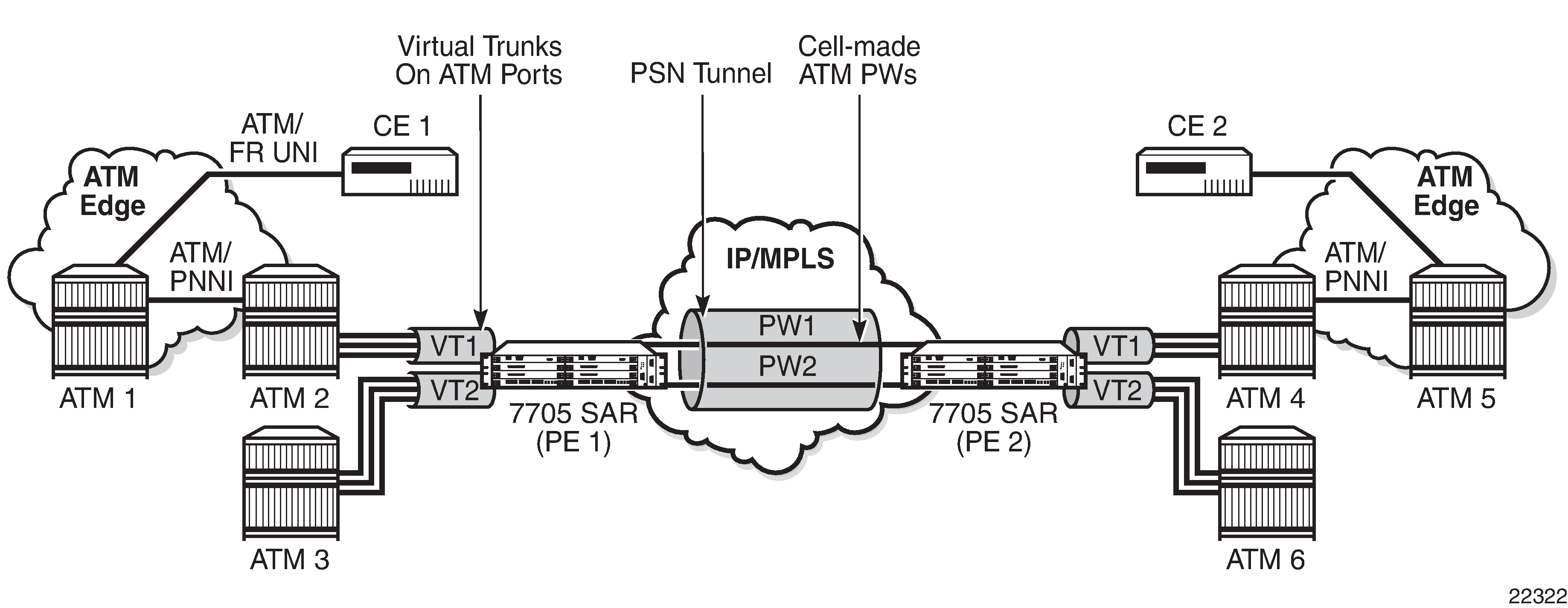
ATM Virtual Trunk Over an IP/MPLS Packet-Switched Network
ATM virtual trunks (VT), also known as ATM transparent cell transport in RFC 4446, provide a transparent trunking function for user and control traffic between two ATM switches over an ATM pseudowire. ATM control traffic includes PNNI signaling and routing traffic, ILMI traffic, and F4/F5 OAM traffic. ATM Virtual Trunk Over IP/ MPLS Packet-Switched Network shows two switches labeled ATM 2 and ATM 4 that appears to be directly connected over an ATM link because the virtual trunk emulates a direct connection between the ATM switches.
Virtual trunks are supported on 7705 SAR 4-port OC3/STM1 Clear Channel Adapter cards with ports configured for OC3 or STM1 and 4-port DS3/E3 Adapter cards with ports configured for DS3 and E3.
All cells arriving on a port configured for virtual trunking on the 7705 SAR are fed to a single ATM pseudowire. The VPI range cannot be configured. No VPI/VCI translation is performed on ingress or egress. Cell order is maintained within a VT. SAP to SAP service is supported. The two ATM ports can therefore be on the same PE node.
By carrying all cells from all VPIs making up the VT in one pseudowire, a transport solution is provided that is both robust and operationally efficient since the entire VT can be managed as a single entity from the NSP NFM-P (single point for configuration, status, alarms, statistics).
ATM virtual trunks use PWE3 N:1 ATM cell mode encapsulation to provide cell-mode transport, supporting all AAL types, over the MPLS network. Cell concatenation on a pseudowire packet is supported. The SDP type can be MPLS or GRE.
The ATM pseudowire is initiated using targeted LDP (T-LDP) signaling (defined in draft-ietfpwe3-control-protocol-xx.txt, Pseudowire Setup and Maintenance using LDP). In this application, there is no ATM signaling on the 7705 SAR gateway nodes since both endpoints of the MPLS network are configured by the network operator. ATM signaling between the ATM nodes is passed transparently over the VT (along with user traffic) from one ATM port on a 7705 SAR PE to another ATM port on a remote (or the same) 7705 SAR PE.
OAM signaling functions in the same way as user traffic in that OAM cells are transported transparently and no special action is taken when F4 or F5 OAM cells are received at the SAP ingress or egress. As well, all ILMI messages are transported transparently between two endpoints. In the case of a pseudowire failure (for example, label withdrawal, loss of reachability, loss of tunnel to the eLER), the virtual trunk service SAP port is not taken down.
ATM SAP-to-SAP Service
ATM VLLs can be configured with both endpoints (SAPs) on the same 7705 SAR. This is referred to as an ATM SAP-to-SAP or local ATM service. An ATM SAP-to-SAP service emulates local ATM switching between two ATM endpoints on the 7705 SAR. Both ingress and egress traffic is legacy ATM traffic. The two SAPs can be any combination of supported ATM encapsulation ports, channel-groups, or IMA bundles.
-
IMA group
-
T1/E1 ASAP port
-
E3/DS3 port
-
OC3/STM1 port. The OC3 port can be configured for clear channel or channelized service.
ATM Traffic Management Support
The 7705 SAR supports the ATM Forum Traffic Management Specification Version 4.1.
Topics in this section include:
Network Ingress Classification
Classification is based on the EXP value of the pseudowire label and EXP-to-FC mapping is determined by the network ingress QoS policy.
The ingress MPLS packets are mapped to forwarding classes based on EXP bits that are part of the headers in the MPLS packets. The EXP bits are used to ensure an end-to-end QoS application. For PW services, there are two labels: one for the MPLS tunnel and one for the pseudowire itself. Mapping is done according to the outer tunnel EXP bit settings. This ensures that if the EXP bit settings are altered along the path by the intermediate LSR nodes, the newly requested FC selection is carried out properly.
Ingress GRE and IP packets are mapped to forwarding classes based on DSCP bit settings of the IP header.
ATM Access Egress Queuing and Shaping
The 7705 SAR provides a per-SAP queuing architecture on the 16-port T1/E1 ASAP Adapter card, 32-port T1/E1 ASAP Adapter card, 4-port DS3/E3 Adapter card, and 4-port OC3/STM1 Clear Channel Adapter card. After the ATM pseudowire is terminated at the access egress point, all the ATM cells are mapped to default queue 1, and queuing is performed on a per-SAP basis.
Access ingress and access egress traffic management features are identical for SAP-to-SAP and SAP-to-SDP applications.
For more information about ATM access egress queuing and scheduling, see the 7705 SAR Quality of Service Guide.
Control Word
ATM VLLs support an optional control word. The control word contains protocol control information and can be enabled to guarantee ordered cell delivery for ATM (Apipe) pseudowire service. See Pseudowire Control Word for more information.
Circuit Emulation VLL (Cpipe) Services
This section provides information about the Cpipe service.
Topics in this section include:
Cpipe configuration information is found under the following topics:
See Service Support for information about the adapter cards and chassis that support circuit emulation VLL services.
Cpipe Service Overview
Cpipe service is the Nokia implementation of TDM PW VLL as defined in the IETF PWE3 working group.
The 7705 SAR can support TDM circuit applications that are able to transport delay-sensitive TDM traffic over a packet network. For example, in the case of cell site aggregation, Cpipe services provide transport service for 2G connectivity between the base transceiver station and the base station controller, and for 3G backhaul applications (for example, EVDO traffic from T1/E1 ports with MLPPP). Cpipe services over MPLS or GRE tunnels are supported.
The 2G traffic is transported encapsulated in a TDM VLL over the packet switched network (PSN). The entire T1/E1 frame or part of a frame (n ✕ 64 kb/s) is carried as a TDM VLL over the PSN. At the far end, the transport layer frame structure is regenerated when structured circuit emulation is used, or simply forwarded as part of the payload when unstructured circuit emulation is used. The 3G UMTS R99 traffic uses ATM/IMA as the transport protocol. The IMA sessions are terminated at the site by the 7705 SAR and the 3G ATM traffic is transported across the PSN through the use of ATM VLLs (PWE3).
TDM SAP-to-SAP Service
TDM VLLs can be configured with both endpoints (SAPs) on the same 7705 SAR. This is referred to as TDM SAP-to-SAP or local TDM service. TDM SAP-to-SAP emulates a TDM multiplexing and switching function on the 7705 SAR.
A TDM SAP-to-SAP connection is set up in the 7705 SAR and a pseudowire is configured between the two endpoints.
Cpipe Service Modes
Cpipe services support unstructured circuit emulation mode (SAToP) for DS3, E3, DS1, and E1 circuits as per RFC 4553 and structured circuit emulation mode (CESoPSN) for n ✕ 64 kb/s timeslots in DS1 and E1 circuits as per RFC 5086.
The 7705 SAR supports MEF 8, which allows both structured and unstructured emulation of TDM services across Epipes, also known as Circuit Emulation Services over Ethernet (CESoETH). See MEF 8 for more information about CESoETH.
Topics in this section include:
Unstructured Mode (SAToP)
Structure-agnostic TDM over Packet (SAToP) is an unstructured circuit emulation mode used for the transport of unstructured TDM or structured TDM (where the structure is ignored).
As a structure-unaware or structure-independent service, SAToP service does not align to any framing; the framing mode for the port is set to unframed. For structured TDM, SAToP disregards the bit sequence and TDM structure in order to transport the entire signal over a PSN as a pseudowire.
SAToP also supports asymmetric delay control (ADC). See Asymmetric Delay Control for information.
SAToP Serial
A satop-serial virtual channel (vc) type can be configured on the 12-port Serial Data Interface card, version 3, to encapsulate serial traffic (subrate or super-rate) directly in the Cpipe without using High Capacity Multiplexing (HCM). This capability allows the transport of serial control leads directly in the pseudowire instead of in HCM and allows the signaling to be transported with any line speed, not just subrate. It also extends support for TDM rates up to 16 Mb/s for the RS-530 interface. For subrate speeds, it can also use less bandwidth than the current HCM implementation, which occupies a full 64 kb/s timeslot.
The SAToP serial capability is supported on RS-530 and RS-232 interfaces.
SAToP Serial Payload Size
The payload size for SAToP serial is configurable using the payload-size command as an integer number of octets and a multiple of 2 (instead of 32 for normal SAToP). This size affects the packet efficiency (that is, the payload-to-header ratio), packetization delay, and packets/s rate. The range is 2 to 1496 octets (instead of 1514 as for other Cpipes). See Cpipe Service Configuration Commands for more information.
SAToP Serial Payload Size Minimums and Defaults shows the payload size minimum values and the defaults. Serial rates of 4800 b/s and lower only support a payload size of 2 bytes.
The minimum payload size is set so that the lowest bit rates can achieve the lowest delays possible and all rates do not exceed 4000 packets/s. The maximum payload size is set so that the packetization delay does not exceed 64 ms.
For rates of 1200 b/s and lower, the system oversamples to 2400 b/s. This results in the same packet size and packets/s as for 2400 b/s. Therefore, a 2-byte payload size is equivalent to 8 bits at 1200 b/s and 4 bits at 600 b/s of ‟real” serial data. Mismatched rate configurations between the two endpoints may not be identified when baud rates are 2400 b/s or lower.
Serial rate (kb/s) |
Minimum Payload Size (bytes) |
Minimum Packetization Delay |
Minimum Packets/s |
Default Payload Size (bytes) |
Default Packetization Delay |
Default Packets/s |
Default Jitter Buffer (ms) |
|---|---|---|---|---|---|---|---|
0.6 |
21 |
— |
150 |
21 |
— |
150 |
32 |
1.2 |
21 |
— |
150 |
21 |
— |
150 |
32 |
2.4 |
2 |
6.67 |
150 |
2 |
6.67 |
150 |
32 |
4.8 |
2 |
333 |
300 |
2 |
3.33 |
300 |
32 |
8 |
2 |
2.00 |
500 |
2 |
2.00 |
500 |
32 |
9.6 |
2 |
1.7 |
600 |
8 |
6.67 |
150 |
32 |
14.4 |
2 |
1.11 |
900 |
8 |
4.44 |
225 |
32 |
16 |
2 |
1.0 |
1000 |
8 |
4.00 |
250 |
32 |
19.2 |
2 |
0.83 |
1200 |
8 |
3.33 |
300 |
32 |
24 |
2 |
0.67 |
1500 |
8 |
2.67 |
375 |
32 |
32 |
2 |
0.50 |
2000 |
8 |
2.00 |
500 |
32 |
38.4 |
2 |
0.42 |
2400 |
8 |
1.67 |
600 |
32 |
56 |
2 |
0.29 |
3500 |
8 |
1.14 |
875 |
32 |
57.6 |
2 |
0.28 |
3600 |
8 |
1.11 |
900 |
32 |
64 |
2 |
0.25 |
4000 |
8 |
1.00 |
1000 |
32 |
115.2 |
8 |
0.56 |
1500 |
64 |
4.44 |
225 |
16 |
128 |
8 |
0.50 |
2000 |
64 |
4.00 |
250 |
16 |
192 |
8 |
0.33 |
3000 |
64 |
2.67 |
375 |
16 |
256 |
8 |
0.25 |
4000 |
64 |
2.00 |
500 |
16 |
288 |
8 |
0.22 |
4500 |
128 |
3.56 |
281 |
8 |
336 |
8 |
0.19 |
5200 |
128 |
3.05 |
328 |
8 |
384 |
32 |
0.67 |
1500 |
128 |
2.67 |
375 |
8 |
512 |
32 |
0.50 |
2000 |
128 |
2.00 |
500 |
8 |
640 |
32 |
0.40 |
2500 |
128 |
1.60 |
625 |
8 |
704 |
32 |
0.36 |
2750 |
128 |
1.45 |
688 |
8 |
768 |
32 |
0.33 |
3000 |
128 |
1.33 |
750 |
8 |
896 |
32 |
0.29 |
3500 |
128 |
1.14 |
875 |
8 |
1024 |
32 |
0.25 |
4000 |
128 |
1.00 |
1000 |
5 |
1152 |
64 |
0.44 |
2250 |
256 |
1.78 |
563 |
5 |
1280 |
64 |
0.40 |
2500 |
256 |
1.60 |
625 |
5 |
1344 |
64 |
0.38 |
2625 |
256 |
1.52 |
656 |
5 |
1408 |
64 |
0.36 |
2750 |
256 |
1.45 |
688 |
5 |
1536 |
64 |
0.33 |
3000 |
256 |
1.33 |
750 |
5 |
1664 |
64 |
0.31 |
3250 |
256 |
1.23 |
813 |
5 |
1792 |
64 |
0.29 |
3500 |
256 |
1.14 |
875 |
5 |
1920 |
64 |
0.27 |
3750 |
256 |
1.07 |
938 |
5 |
2048 |
64 |
0.25 |
4000 |
256 |
1.00 |
1000 |
5 |
3072 |
128 |
0.33 |
3000 |
256 |
0.67 |
1500 |
5 |
4096 |
128 |
0.25 |
4000 |
256 |
0.50 |
2000 |
5 |
5120 |
256 |
0.40 |
2500 |
1024 |
1.60 |
625 |
5 |
6144 |
256 |
0.33 |
3000 |
1024 |
1.33 |
750 |
5 |
7168 |
256 |
0.29 |
3500 |
1024 |
1.14 |
875 |
5 |
8192 |
256 |
0.25 |
4000 |
1024 |
1.00 |
1000 |
5 |
9216 |
512 |
0.44 |
2250 |
1024 |
0.89 |
1125 |
5 |
10240 |
512 |
0.40 |
2500 |
1024 |
0.80 |
1250 |
5 |
11264 |
512 |
0.36 |
2750 |
1024 |
0.73 |
1375 |
5 |
12288 |
512 |
0.33 |
3000 |
1024 |
0.67 |
1500 |
5 |
13312 |
512 |
0.31 |
3250 |
1024 |
0.62 |
1625 |
5 |
14336 |
512 |
0.29 |
3500 |
1024 |
0.57 |
1750 |
5 |
14360 |
512 |
0.27 |
3750 |
1024 |
0.53 |
1875 |
5 |
16384 |
512 |
0.25 |
4000 |
1024 |
0.50 |
2000 |
5 |
Note:
600 and 1200 b/s are oversampled to 2400 b/s.
SAToP Serial Jitter Buffer
For each circuit, the maximum receive jitter buffer is configurable using the jitter-buffer command. See Cpipe Service Configuration Commands for more information. Playout from this buffer must start when the buffer is 50% full to give an operational packet delay variance (PDV) equal to half the maximum buffer size. The supported range is 12 to 250 ms in increments of 1 ms. The buffer size must be set to at least three times the packetization delay and not more than 32 times the packetization delay.
The default jitter buffer values are shown in SAToP Serial Payload Size Minimums and Defaults .
Jitter buffer overrun and underrun counters are available via statistics and may be optionally alarmed while the circuit is up. On overruns, excess packets are discarded and counted. On underruns, all ones are sent for unstructured circuits.
The circuit status is tracked to show a status of either up, loss of packets, or administratively down. Statistics are available for the number of in-service seconds and the number of out-of-service seconds when the circuit is administratively up.
SAToP Teleprotection Interface
The 8-port C37.94 Teleprotection card supports the SAToP teleprotection interface (TPIF) VC type, making it possible to transport the entire C37.94 signal, which is 2.048 Mb/s. Because this transport rate is the same rate as an E1 circuit, the encapsulation is as per RFC 4553. The SAToP TPIF VC type extends the current capability to transport n x 64 kb/s channels within the C37.94 frame using CESoPSN.
The 8-port C37.94 Teleprotection card supports a maximum of four clear channel C37.94 ports for SAToP service. The card consists of four pairs of ports (ports 1/2, 3/4, 5/6, and 7/8). Only the odd-numbered port in each pair can be configured for SAToP, unframed C37.94. If a port is configured for SAToP, the even-numbered port cannot be used for framed or unframed service.
The SAToP TPIF VC has a configurable payload size and a configurable jitter buffer size. For information about configuring the payload size and jitter buffer, see Packet Payload Size and Jitter Buffer.
The SAToP TPIF VC also supports asymmetric delay control (ADC). See Asymmetric Delay Control for information.
Structured Mode (CESoPSN)
Structure-aware circuit emulation is used for the transport of structured TDM, taking at least some level of the structure into account. By selecting only the necessary n ✕ 64 kb/s timeslots to transport, bandwidth usage is reduced or optimized (compared to a full DS1 or E1). Full DS1s or E1s can be transported by selecting all the timeslots in the DS1 or E1 circuit. Framing bits (DS1) or FAS (E1) are terminated at the near end and reproduced at the far end.
The 7705 SAR supports CESoPSN with and without Channel Associated Signaling (CAS) for DS1 and E1.
When CESoPSN with CAS is selected, the ABCD bits are coded into the T1 or E1 multiframe packets, transported within the TDM PW, and reconstructed in the T1 or E1 multiframe at the far end for each timeslot.
CAS includes four signaling bits (A, B, C, and D) in the messages sent over a voice trunk. These messages provide information such as the dialed digits and the call state (whether on-hook or off-hook).
The mechanism for E1 CAS is described in ITU-T G.732. When configured for E1 CAS, timeslot 17 carries the signaling information for the timeslots used for voice trunking. Each channel requires four signaling bits, so grouping 16 E1 frames into a multiframe allows the signaling bits for all 30 channels to be trunked.
As shown in E1 Framing for CAS Support in an E1 Multiframe, timeslot 1 of all frames within the E1 multiframe is reserved for alignment, alarm indication, and CRC. For Frame 0, timeslot 17 is reserved for multiframe alignment bits. For the remaining 15 frames, timeslot 17 contains ABCD bits for two channels.
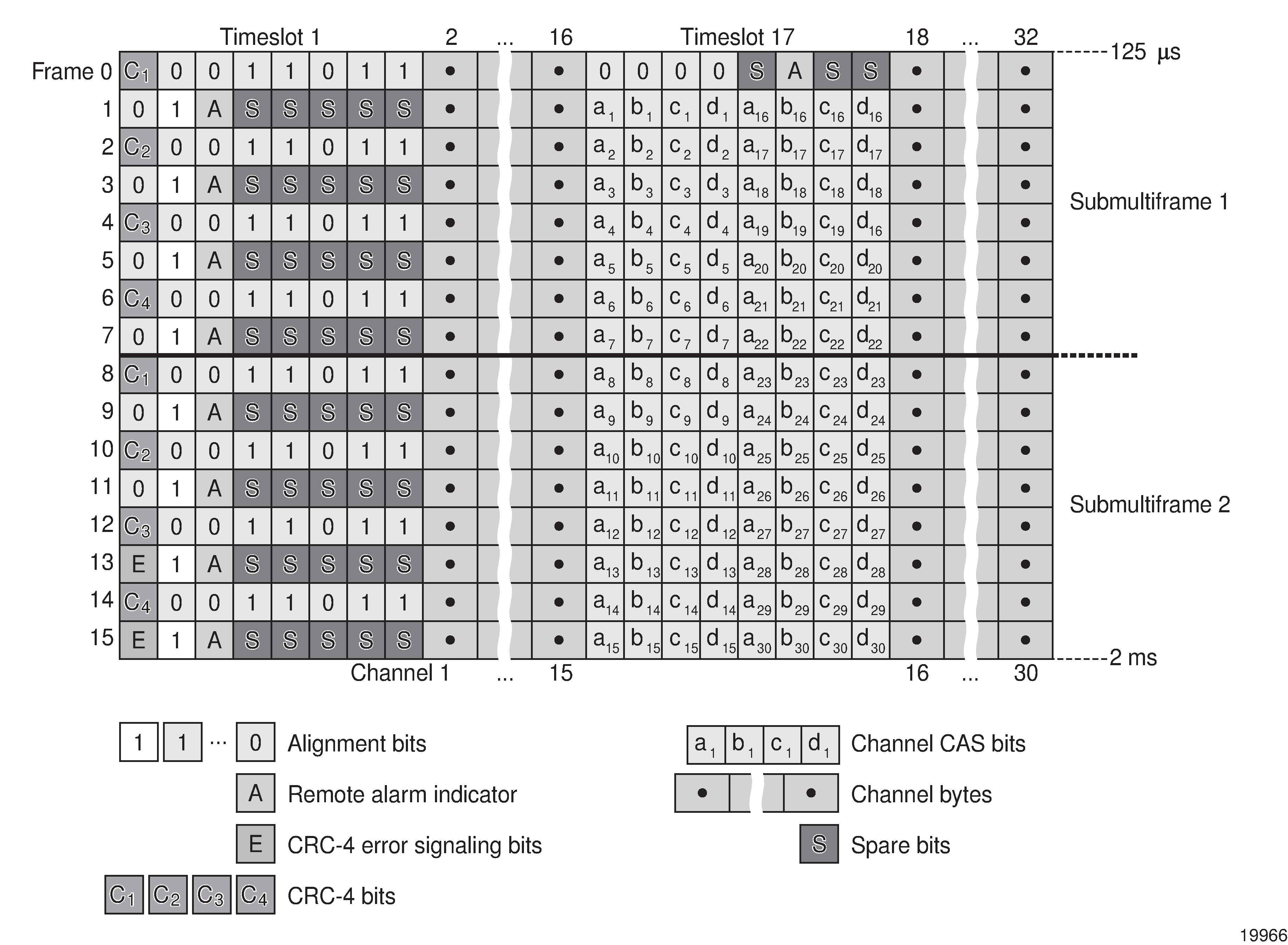
For T1 CAS, the signaling bits are transferred using Robbed Bit Signaling (RBS), where the least significant bit in the channel is used periodically to transport these bits instead of voice data. T1 CAS is supported when extended superframe format (ESF) or superframe format (SF) framing is configured. ESF framing uses a 24-frame multiframe and transfers all four signaling bits (ABCD). SF framing uses a 12-frame multiframe and transfers only the AB bits. The signaling bits are carried in the least significant bit of the following frames:
A bit in frame 6
B bit in frame 12
C bit in frame 18
D bit in frame 24
When CESoPSN with CAS is selected, the ABCD bits are decoded from the incoming E1/T1 multiframe, transferred within the TDM PW, and reconstructed in the E1/T1 multiframe at the far end for every DS0 channel. CAS can be configured on a per-T1/E1 basis or on a per-DS0/64 kb/s channel basis.
In previous releases, when a Cpipe was configured for CESoPSN with CAS, the T1 ports at each end of the Cpipe had to be configured for the same framing format: either ESF or SF. If the framing formats did not match, a SapParamMismatch alarm was raised.
The 7705 SAR now supports mixed framing formats for the T1 ports on a Cpipe configured for CESoPSN with CAS; that is, one port can be configured for ESF framing and the other port for SF framing.
If the ingress port is an ESF-framed T1 port, when the packets arrive at the egress port, the ABCD bits from the ingress ESF SAP are sent out as AB bits in two consecutive superframes on the egress SF SAP. The CD bits from the ingress ESF SAP are mapped as AB bits in the second SF frame.
If the ingress port is an SF-framed T1 port, when the packets arrive at the egress port, the AB bits from every second SF frame from the ingress SF SAP are repeated twice as the ABCD bits of an egress ESF frame. The AB bits from the interlacing SF frames are dropped.
ESF and SF framing interoperability is supported on DS1 (T1) ports or channels on the following hardware:
16-port T1/E1 ASAP Adapter card
32-port T1/E1 ASAP Adapter card
2-port OC3/STM1 Channelized Adapter card
4-port DS3/E3 Adapter card
4-port OC3/STM1 / 1-port OC12/STM4 Adapter card
4-port T1/E1 and RS-232 Combination module (supported on the 7705 SAR-H)
7705 SAR-A (variant with T1/E1 ports)
7705 SAR-M (variants with T1/E1 ports)
7705 SAR-X
T1 Framing for CAS (RBS) Support in a T1 ESF Multiframe shows the structure of a T1 ESF multiframe that uses RBS. The structure of a T1 SF multiframe is based on 12 frames and only the A and B bits are available.
Frame Number |
F Bit |
Bit Numbers in Each Channel Timeslot |
Signaling Channel Designation4 |
||||
|---|---|---|---|---|---|---|---|
Bit Number within Multiframe |
Assignments |
||||||
FAS 1 |
DL 2 |
CRC 3 |
For Character Signal4 |
For Signaling 4 |
|||
1 |
1 |
— |
m |
— |
1-8 |
— |
— |
2 |
194 |
— |
— |
e1 |
1-8 |
— |
— |
3 |
387 |
— |
m |
— |
1-8 |
— |
— |
4 |
580 |
0 |
— |
— |
1-8 |
— |
— |
5 |
773 |
— |
m |
— |
1-8 |
— |
— |
6 |
966 |
— |
— |
e2 |
1-7 |
8 |
A |
7 |
1159 |
— |
m |
— |
1-8 |
— |
— |
8 |
1352 |
0 |
— |
— |
1-8 |
— |
— |
9 |
1545 |
— |
m |
— |
1-8 |
— |
— |
10 |
1738 |
— |
— |
e3 |
1-8 |
— |
— |
11 |
1931 |
— |
m |
— |
1-8 |
— |
— |
12 |
2124 |
1 |
— |
— |
1-7 |
8 |
B |
13 |
2317 |
— |
m |
— |
1-8 |
— |
— |
14 |
2510 |
— |
— |
e4 |
1-8 |
— |
— |
15 |
2703 |
— |
m |
— |
1-8 |
— |
— |
16 |
2896 |
0 |
— |
— |
1-8 |
— |
— |
17 |
3089 |
— |
m |
— |
1-8 |
— |
— |
18 |
3282 |
— |
— |
e5 |
1-7 |
8 |
C |
19 |
3475 |
— |
m |
— |
1-8 |
— |
— |
20 |
3668 |
1 |
— |
— |
1-8 |
— |
— |
21 |
3861 |
— |
m |
— |
1-8 |
— |
— |
22 |
4054 |
— |
— |
e6 |
1-8 |
— |
— |
23 |
4247 |
— |
m |
— |
1-8 |
— |
— |
24 |
4440 |
1 |
— |
— |
1-7 |
8 |
D |
Notes:
FAS = frame alignment signal (....001011.....)
DL = 4 kb/s data link (m represents message bits)
CRC = CRC-6 block check field (e1 to e6 represent check bits)
Only applicable for CAS
TDM PW Encapsulation
TDM circuits are MPLS-encapsulated as per RFC 4553 (SAToP) and RFC 5086 (CESoPSN). (see SAToP MPLS Encapsulation and CESoPSN MPLS Encapsulation).
For GRE tunnels, the same encapsulations shown in CESoPSN MPLS Encapsulation are used, but GRE tunnel headers are used instead of MPLS tunnel headers.

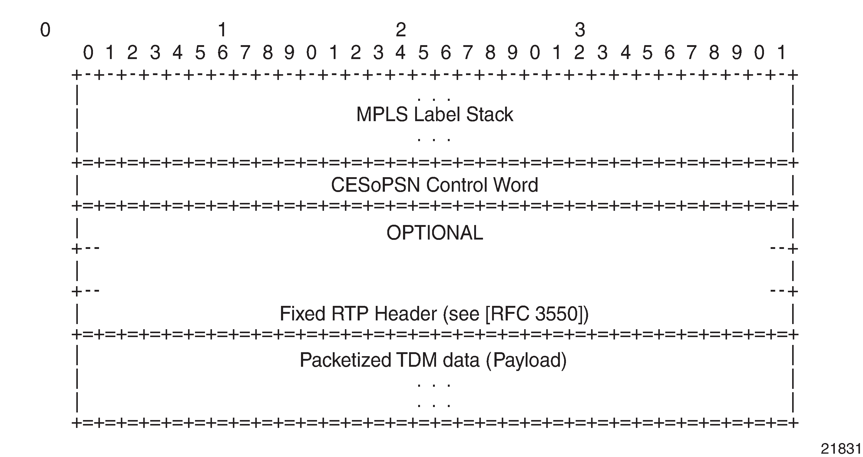
CESoPSN Packet Payload Format for Trunk-Specific n x 64 kb/s (With and Without CAS Transport) shows the format of the CESoPSN TDM payload (with and without CAS) for packets carrying trunk-specific n ✕ 64 kb/s service.
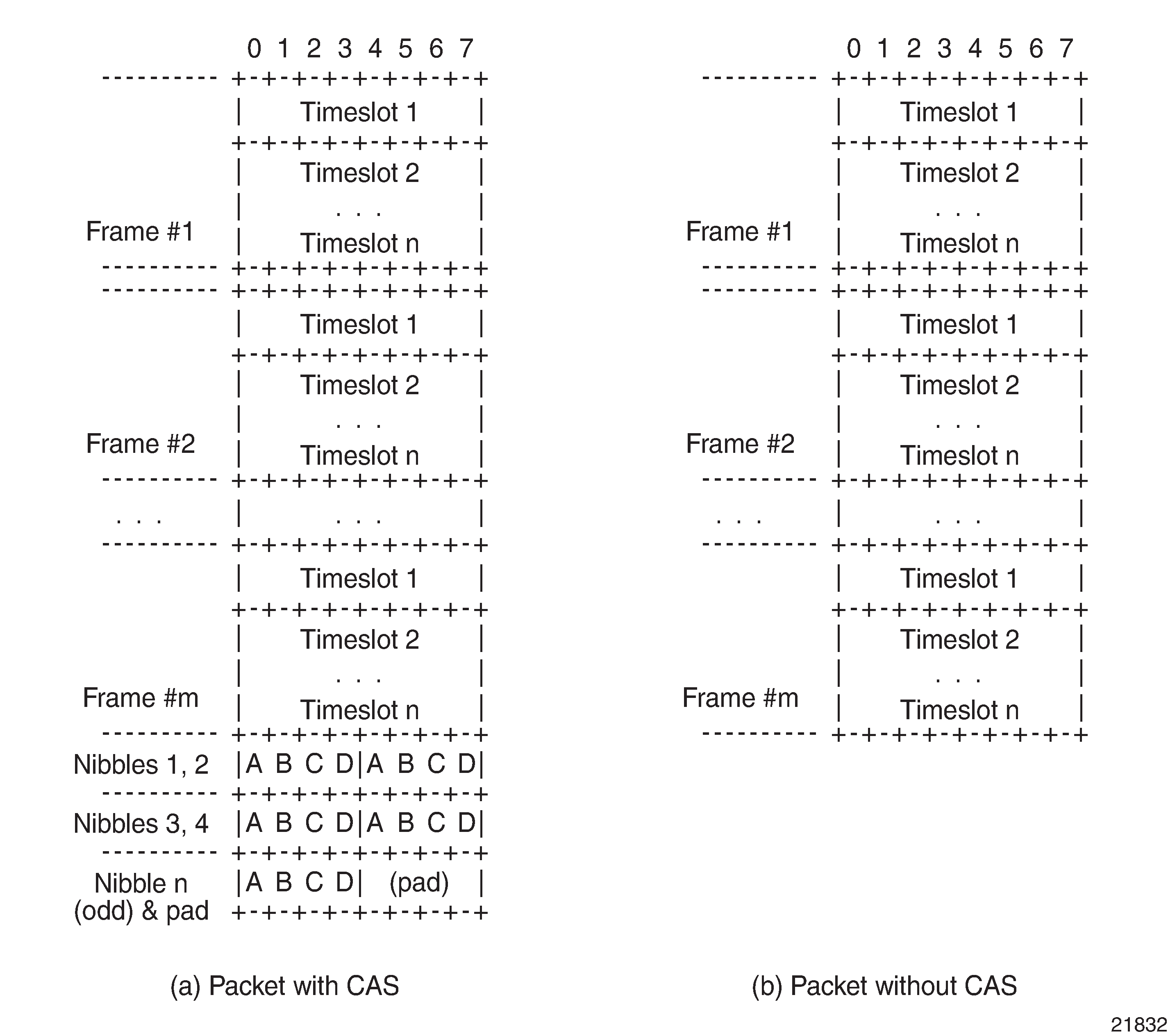
For CESoPSN without CAS, select the packet size so that an integer number of frames are transported. That is, if n timeslots per frame are to be encapsulated in a TDM PW, then the packet size must be a multiple of n (where n is not equal to 1). For example, if n = 4 timeslots, then the packet size can be 8, 12, 16, and so on. If only one timeslot per frame is being transported, the packet size must be an even number.
For CESoPSN with CAS, the packet size is an integer number of frames. A single T1/E1 port can have a mix of CAS and non-CAS traffic in each DS0/64 kb/s channel. You must configure the relevant T1/E1 port or channel group for CAS signal mode before provisioning the TDM PW with CAS or the system will disallow the signal mode configuration. The extra bytes for ABCD (CAS) signaling bits are not included when setting the packet size.
For a single T1/E1 port that contains a mix of CAS and non-CAS signaling, all the non-CAS channel Cpipes inherit the CAS channel restriction concerning 24/16 frames for payload size. For a T1 port, the payload size is equal to the number of CAS and/or non-CAS timeslots ✕ 24 frames/multiframe ✕ n multiframes, where n = 1 to 8. For an E1 port, the payload size is equal to the number of CAS and/or non-CAS timeslots ✕ 16 frames/multiframe ✕ n multiframes, where n =1 to 8.
Circuit Emulation Parameters and Options
Cpipe services support unstructured circuit emulation mode (SAToP) for DS3, E3, DS1, and E1 circuits as per RFC 4553, and structured circuit emulation mode (CESoPSN) for n ✕ 64 kb/s timeslots in DS1 and E1 circuits as per RFC 5086.
SAToP and CESoPSN Support on the 7705 SAR lists the adapter cards, modules, and chassis that support SAToP and CESoPSN.
Card/Module/Chassis |
SAToP |
CESoPSN |
|
|---|---|---|---|
Name |
CLI identifier (includes mode and channelization) |
||
16-port T1/E1 ASAP Adapter Card |
a16-chds1v2 |
||
On DS0/64k |
✓ |
||
On DS1/E1 |
✓ |
||
32-port T1/E1 ASAP Adapter Card |
a32-chds1v2 |
||
On DS0/64k |
✓ |
||
On DS1/E1 |
✓ |
||
2-port OC3/STM1 Channelized Adapter Card |
a2-choc3 |
||
On DS0/64k |
✓ |
||
On DS1/E1 |
✓ |
||
On DS31 |
✓ |
||
4-port OC3/STM1 / 1-port OC12/STM4 Adapter Card |
a4-choc3/12 |
||
On DS1/E1 |
✓ |
||
4-port DS3/E3 Adapter Card, version 1 and version 2 |
a4-chds3, a4-chds3v2 |
||
On n ✕ DS0 |
✓ |
||
On DS12 |
✓ |
||
On DS3/E3 |
✓ |
||
12-port Serial Data Interface Card, version 2 |
a12-sdiv2 |
||
On V.35 and X.21 ports |
✓ |
||
On RS-232 ports |
✓ |
||
12-port Serial Data Interface Card, version 3 |
a12-sdiv3 |
||
On V.35 and X.21 ports |
✓ |
||
On RS-232 ports |
✓ (SAToP serial) |
✓ |
|
On RS-530 ports |
✓ (SAToP serial) |
✓ |
|
6-port E&M Adapter Card |
a6-em |
✓ |
|
8-port Voice & Teleprotection Card |
a8-vt |
✓ |
|
8-port C37.94 Teleprotection Card |
a8-c3794 |
✓ (SAToP TPIF) |
✓ |
8-port FXO Adapter Card |
a8-fxo |
✓ |
|
6-port FXS Adapter Card |
a6-fxs |
✓ |
|
Integrated Services Card |
isc |
✓3 |
|
4-port T1/E1 and RS-232 Combination Module |
a4-combo |
||
On RS-232 ports |
✓ |
||
On T1/E1 ports |
✓ |
✓ |
|
7705 SAR-A |
i8-chds1 |
✓ |
✓ |
7705 SAR-Hc |
i2-sdi |
✓ |
|
7705 SAR-M |
i16-chds1 |
✓ |
✓ |
7705 SAR-X |
i8-chds1-x |
✓ |
✓ |
Notes:
No support for E3
No support for E1/64K channel groups
The Integrated Services card acts as a Cpipe bridge/multicaster. There are no physical ports on the Integrated Services card.
See Service Support for more information about circuit emulation VLL services.
The following parameters and options are described in this section:
Unstructured
Unstructured CES is configured by choosing satop-t1, satop-e1, satop-t3, satop-e3, or satop-tpif as the vc-type when creating a Cpipe service. For DS1, E1, and TPIF unstructured circuit emulation, the framing parameter of the port must be set to ds1-unframed, e1-unframed, and unframed (respectively) because SAToP service ignores the underlying framing. Additionally, channel group 1 must contain all 24 or 32 timeslots, which is configured automatically when channel group 1 is created.
For DS1, E1, DS3, and E3 circuit emulation, the payload packet size is configurable and must be an integer value between 64 and 1514 octets and a multiple of 32. The payload packet size affects the packet efficiency and packetization delay. Unstructured Payload Defaults shows the default values for packet size and packetization delay. See Packet Payload Size for more information.
Circuit |
Payload Size (Octets) |
Packetization Delay (ms) |
|---|---|---|
DS1 |
192 |
1.00 |
E1 |
256 |
1.00 |
DS3 |
1024 |
0.183 |
E3 |
1024 |
0.238 |
Structured DS1/E1 CES without CAS
Structured CES without CAS is configured by choosing cesopsn as the vc-type when creating a Cpipe service. For n ✕ 64 kb/s structured circuit emulation operation, the framing parameter of the port must be set to a framed setting (such as ESF for DS1). Each channel group contains n DS0s (timeslots), where n is between 1 and 24 timeslots for DS1 and between 1 and 31 timeslots for E1.
The packet payload size is configurable (in octets) and must be an integer multiple of the number of timeslots in the channel group. The minimum payload packet size is 2 octets (based on two frames per packet and one timeslot per frame). See Default and Minimum Payload Size for CESoPSN without CAS for default and minimum payload size values. The maximum payload packet size is 1514 octets.
If a port on a 16-port T1/E1 ASAP Adapter card or 32-port T1/E1 ASAP Adapter card is configured for DCR, the port timing is associated with the service clock of the Cpipe of channel group 1.
For a framed T1 port, there is a restriction on the Cpipe payload size of channel group 1:
for DCR with a timestamp frequency of 77.76 MHz, the payload size = 2 x I x (number of timeslots), where I = 1 to 20
for DCR with a timestamp frequency of 19.44 MHz, the payload size = 8 x I x (number of timeslots), where I = 1 to 5
This restriction does not apply to framed E1 ports or unframed T1/E1 ports.
Each DS1 or E1 frame contributes a number of octets to the packet payload. That number is equal to the number of timeslots configured in the channel group. Thus, a channel group with four timeslots contributes 4 octets to the payload. The timeslots do not need to be contiguous.
A smaller packet size results in a lower packetization delay; however, it increases the packet overhead (when expressed as a percentage of the traffic).
Calculation of Payload Size
The payload size (S), in octets, can be calculated using the following formula:
S = N x F
where:
N = the number of octets (timeslots) collected per received frame (DS1 or E1)
F = the number of received frames (DS1 or E1) that are accumulated in each CESoPSN packet
For example, assume the packet collects 16 frames (F) and the channel group contains 4 octets (timeslots) (N). Then the packet payload size (S) is:
S = 4 octets/frame x 16 frames
= 64 octets
Calculation of Packetization Delay
Packetization delay is the time needed to collect the payload for a CESoPSN packet. DS1 and E1 frames arrive at a rate of 8000 frames per second. Therefore, the received frame arrival period is 125 μs.
In the previous example, 16 frames were accumulated in the CESoPSN packet. In this case, the packetization delay (D) can be calculated as follows:
D = 125 μs/frame ✕ 16 frames
= 2.000 ms
Default and Minimum Payload Size for CESoPSN without CAS shows the default and minimum values for frames per packet, payload size, and packetization delay as they apply to the number of timeslots (N) that contribute to the packet payload. The default values are set by the operating system as follows:
for N = 1, the default is 64 frames/packet
for 2 ≤ N ≤ 4, the default is 32 frames/packet
for 5 ≤ N ≤ 15, the default is 16 frames/packet
for N ≥ 16, the default is 8 frames/packet
Default Values |
Minimum Values |
|||||
|---|---|---|---|---|---|---|
Number of Timeslots (N) |
Frames per Packet (F) |
Payload Size (Octets) (S) |
Packetization Delay (ms) (D) |
Frames per Packet (F) |
Payload Size (Octets) (S) |
Packetization Delay (ms) (D) |
1 |
64 |
64 |
8.000 |
2 |
2 |
0.250 |
2 |
32 |
64 |
4.000 |
2 |
4 |
0.250 |
3 |
32 |
96 |
4.000 |
2 |
6 |
0.250 |
4 |
32 |
128 |
4.000 |
2 |
8 |
0.250 |
5 |
16 |
80 |
2.000 |
2 |
10 |
0.250 |
6 |
16 |
96 |
2.000 |
2 |
12 |
0.250 |
7 |
16 |
112 |
2.000 |
2 |
14 |
0.250 |
8 |
16 |
128 |
2.000 |
2 |
16 |
0.250 |
9 |
16 |
144 |
2.000 |
2 |
18 |
0.250 |
10 |
16 |
160 |
2.000 |
2 |
20 |
0.250 |
11 |
16 |
176 |
2.000 |
2 |
22 |
0.250 |
12 |
16 |
192 |
2.000 |
2 |
24 |
0.250 |
13 |
16 |
208 |
2.000 |
2 |
26 |
0.250 |
14 |
16 |
224 |
2.000 |
2 |
28 |
0.250 |
15 |
16 |
240 |
2.000 |
2 |
30 |
0.250 |
16 |
8 |
128 |
1.000 |
2 |
32 |
0.250 |
17 |
8 |
136 |
1.000 |
2 |
34 |
0.250 |
18 |
8 |
144 |
1.000 |
2 |
36 |
0.250 |
19 |
8 |
152 |
1.000 |
2 |
38 |
0.250 |
20 |
8 |
160 |
1.000 |
2 |
40 |
0.250 |
21 |
8 |
168 |
1.000 |
2 |
42 |
0.250 |
22 |
8 |
176 |
1.000 |
2 |
44 |
0.250 |
23 |
8 |
184 |
1.000 |
2 |
46 |
0.250 |
24 |
8 |
192 |
1.000 |
2 |
48 |
0.250 |
25 |
8 |
200 |
1.000 |
2 |
50 |
0.250 |
26 |
8 |
208 |
1.000 |
2 |
52 |
0.250 |
27 |
8 |
216 |
1.000 |
2 |
54 |
0.250 |
28 |
8 |
224 |
1.000 |
2 |
56 |
0.250 |
29 |
8 |
232 |
1.000 |
2 |
58 |
0.250 |
30 |
8 |
240 |
1.000 |
2 |
60 |
0.250 |
31 |
8 |
248 |
1.000 |
2 |
62 |
0.250 |
Structured T1/E1 CES with CAS
Structured circuit emulation with CAS is supported for T1 and E1 circuits.
Structured CES with CAS service is configured by choosing cesopsn-cas as the vc-type when creating a Cpipe service. The DS1 or E1 service on the port associated with the Cpipe SAP should be configured to support CAS (via the signal-mode {cas} command) before configuring the Cpipe service to support DS1 or E1 with CAS. See the 7705 SAR Interface Configuration Guide for information about configuring signal mode.
For n ✕ DS0 and n ✕ 64 kb/s structured circuit emulation with CAS, the implementation is almost identical to that of CES without CAS. When CAS operation is enabled, timeslot 16 (channel 17) cannot be included in the channel group on E1 carriers. Since the CAS in-band method is used, separate PW support for CAS is not provided.
When CAS is enabled, the packet size is based on the number of multiframes per packet and whether the circuit is configured for E1 or T1. Payload size is user-configurable to correspond to the desired integer number of multiframes. The 7705 SAR supports up to 8 multiframes, where a multiframe contains 24 frames for T1 and 16 frames for E1. Therefore, the payload size = number of timeslots ✕ 24 (T1) or 16 (E1) frames per multiframe ✕ number of multiframes. For example, the payload size for a T1 line (24 frames) using 2 timeslots and 8 multiframes is 384 bytes (384 = (2 ✕ 24) ✕ 8).
Multiple multiframes are supported on the following cards and platforms:
6-port E&M Adapter card (see note below)
16-port T1/E1 ASAP Adapter card
32-port T1/E1 ASAP Adapter card
7705 SAR-A (variant with T1/E1 ports)
7705 SAR-M (variants with T1/E1 ports)
7705 SAR-X
Default Values for the Payload Size for T1 and E1 CESoPSN with CAS shows the default payload sizes based on the number of timeslots.
For CAS, the signaling portion adds (n/2) bytes (n is an even integer) or ((n+1)/2) bytes (n is odd) to the packet, where n is the number of timeslots in the channel group. You do not include the additional signaling bytes when setting the TDM payload size. However, the operating system includes the additional bytes in the total packet payload, and the total payload must be accounted for when setting the service-mtu size. Continuing the example above, since n = 4, the total payload is 64 octets plus (4/2 = 2) CAS octets, or 66 octets. Refer to CESoPSN Packet Payload Format for Trunk-Specific n x 64 kb/s (With and Without CAS Transport) to see the structure of the CES with CAS payload.
CES fragmentation is not supported.
Number of Timeslots |
T1 |
E1 |
||||
|---|---|---|---|---|---|---|
Number of Frames per Packet |
Payload Size (Octets) |
Packetization Delay (ms) |
Number of Frames per Packet |
Payload Size (Octets) |
Packetization Delay (ms) |
|
1 |
24 |
24 |
3.00 |
16 |
16 |
2.00 |
2 |
24 |
48 |
3.00 |
16 |
32 |
2.00 |
3 |
24 |
72 |
3.00 |
16 |
48 |
2.00 |
4 |
24 |
96 |
3.00 |
16 |
64 |
2.00 |
5 |
24 |
120 |
3.00 |
16 |
80 |
2.00 |
6 |
24 |
144 |
3.00 |
16 |
96 |
2.00 |
7 |
24 |
168 |
3.00 |
16 |
112 |
2.00 |
8 |
24 |
192 |
3.00 |
16 |
128 |
2.00 |
9 |
24 |
216 |
3.00 |
16 |
144 |
2.00 |
10 |
24 |
240 |
3.00 |
16 |
160 |
2.00 |
11 |
24 |
264 |
3.00 |
16 |
176 |
2.00 |
12 |
24 |
288 |
3.00 |
16 |
192 |
2.00 |
13 |
24 |
312 |
3.00 |
16 |
208 |
2.00 |
14 |
24 |
336 |
3.00 |
16 |
224 |
2.00 |
15 |
24 |
360 |
3.00 |
16 |
240 |
2.00 |
16 |
24 |
384 |
3.00 |
16 |
256 |
2.00 |
17 |
24 |
408 |
3.00 |
16 |
272 |
2.00 |
18 |
24 |
432 |
3.00 |
16 |
288 |
2.00 |
19 |
24 |
456 |
3.00 |
16 |
304 |
2.00 |
20 |
24 |
480 |
3.00 |
16 |
320 |
2.00 |
21 |
24 |
504 |
3.00 |
16 |
336 |
2.00 |
22 |
24 |
528 |
3.00 |
16 |
352 |
2.00 |
23 |
24 |
552 |
3.00 |
16 |
368 |
2.00 |
24 |
24 |
576 |
3.00 |
16 |
384 |
2.00 |
25 |
NA |
NA |
NA |
16 |
400 |
2.00 |
26 |
NA |
NA |
NA |
16 |
416 |
2.00 |
27 |
NA |
NA |
NA |
16 |
432 |
2.00 |
28 |
NA |
NA |
NA |
16 |
448 |
2.00 |
29 |
NA |
NA |
NA |
16 |
464 |
2.00 |
30 |
NA |
NA |
NA |
16 |
480 |
2.00 |
Packet Payload Size
The packet payload size defines the number of octets contained in the payload of a TDM PW packet when the packet is transmitted. Each DS0 (timeslot) in a DS1 or E1 frame contributes 1 octet to the payload, and the total number of octets contributed per frame depends on the number of timeslots in the channel group (for example, 10 timeslots contribute 10 octets per frame).
Jitter Buffer
A circuit emulation service uses a jitter buffer to ensure that received packets are tolerant to packet delay variation (PDV). The selection of jitter buffer size must take into account the size of the TDM-encapsulated packets (payload size). A properly configured jitter buffer provides continuous play-out, thereby avoiding discards due to overruns and underruns (packets arriving too early or too late). The maximum receive jitter buffer size is configurable for each SAP configured for circuit emulation. The range of values is from 1 to 250 ms in increments of 1 ms.
Configuration and Design Considerations
Determining the best configuration value for the jitter buffer may require some adjustments to account for the requirements of your network, which can change PDV as nodes are added or removed.
For each circuit, the maximum receive jitter buffer is configurable. Play-out from this buffer must start when the buffer is 50% full, in order to give an operational PDV equal to half the maximum buffer size. The supported range is 1 to 250 ms in increments of 1 ms. The buffer size must be set to at least 3 times the packetization delay and no greater than 32 times the packetization delay. Use a buffer size (in ms) that is equal to or greater than the peak-to-peak PDV expected in the network used by circuit emulation service. For example, for a PDV of ±5 ms, configure the jitter buffer to be at least 10 ms.
The jitter buffer setting and payload size (packetization delay) interact such that it may be necessary for the operating system to adjust the jitter buffer setting in order to ensure no loss of packets. Thus, the configured jitter buffer value may not be the value used by the system. Use the show>service>id service-id>all command to show the effective PDVT (packet delay variation tolerance).
If asymmetric delay control is enabled (asym-delay-control), it must be enabled on both ends of the Cpipe and the jitter buffer size must match on both ends of the Cpipe; otherwise, a service parameter mismatch state occurs and the service is brought down.
The following values are the default jitter buffer times for structured circuits without CAS, where N is the number of timeslots:
for N = 1, the default is 32 ms
for 2 ≤ N ≤ 4, the default is 16 ms
for 5 ≤ N ≤ 15, the default is 8 ms
for N ≥ 16, the default is 5 ms
For CESoPSN with CAS, the default jitter buffer is 12 ms for T1 and 8 ms for E1.
Jitter buffer overrun and underrun counters are available for statistics and can raise an alarm (optional) while the circuit is operational. For overruns, excess packets are discarded and counted. For underruns, an all-ones pattern is sent for unstructured circuits and an all-ones or a user-defined pattern is sent for structured circuits (based on configuration).
The circuit status and statistics can be displayed using the show command.
Asymmetric Delay Control
If there is high jitter in the network, the last packet for initialization of the circuit emulation service may arrive early or late, resulting in a jitter buffer latency that is different from the expected configured jitter buffer setting (time associated with 50% jitter buffer size). The latency difference between each direction of the TDM PW is known as asymmetric latency, and because some applications (for example, power industry networks) require a very low latency difference, it must be controlled.
Asymmetric delay control (ADC) is used to control the asymmetric latency contributed by the jitter buffer. When the asym-delay-control command is enabled, a special startup sequence is triggered when the TDM PW is initially started or is restarted after being brought down (due to faults such as packet overflow, packet underflow, or the port going down).
Upon startup, a configurable number of TDM PW packets are analyzed. During this analysis period, the access port transmits an all-ones pattern (for the 8-port Voice & Teleprotection card or 8-port C37.94 Teleprotection card) or the configured idle-payload-fill value (for the other port types). See the 7705 SAR Interface Configuration Guide for information on the idle-payload-fill command. The service is considered to be down during this period.
If any packet loss is detected during the analysis period, the analysis is restarted. If no packet loss is detected, the average jitter buffer latency is computed. Based on the difference between the average latency and the expected latency of the jitter buffer size, the network processor will either:
drop a number of octets based on the difference (if the measured average is higher than expected)
add a number of dummy octets based on the difference (if the measured average is lower than expected); the dummy octets are based on the idle-payload-fill value of the channel or port
ADC can only reduce asymmetry in the jitter buffer. It does not reduce any asymmetry that may exist in the network path.
Because of this, the network must be engineered to maintain symmetrical latency:
use explicit-path LSPs with strict hops using RSVP-TE or SR-TE
do not use MPLS FRR or loop-free alternate paths (LFA, R-LFA, or TI-LFA) anywhere along the path because it may change the latency characteristics of a single direction without changing the other direction
ensure that both directions of the TDM PW traverse the same path end to end
With ADC, care must be taken when designing the network to prevent a situation where an error recovery mechanism would result in different MPLS paths in the two directions of the Cpipe, between the two SAPs across the network. If different paths are used, latencies may be different, causing asymmetry. To prevent this situation, the 7705 SAR supports path redundancy for ADC. See ADC for Redundant Paths.
Optionally, the ADC analysis can be set to repeat at configured time intervals after the service is up. This analysis is done with live traffic (that is, not with all-ones or the idle-payload-fill value). If the difference between the calculated average latency and the expected latency is greater than the threshold-repeat value, octets are added or dropped as necessary.
On-demand ADC allows users to initiate a one-time ADC analysis and correction on a live service using the tools>perform>service>id>sap command. Similar to the ADC repeat function, ADC uses the threshold-repeat value to determine if octets need to be added or dropped.
If ADC is enabled, it must be enabled on both ends of the Cpipe; otherwise, a service parameter mismatch state occurs and the service is brought down. Jitter buffer size is also included in the set of parameters that will cause a service parameter mismatch if the value is not the same at both ends of the Cpipe. This prevents the operator from changing the jitter buffer size, which would immediately change the latency symmetry of the Cpipe service.
As well, Cpipes using ADC must have the same card and port type on both ends of the Cpipe. Mismatched card/port configuration is not blocked in the CLI or in SNMP but must be avoided; otherwise, differential delay will be introduced caused by different framer delays on the cards/ports.
ADC can only be enabled for Cpipes configured as CESoPSN without CAS, SAToP TPIF, or SAToP (applies only to E1 circuits on the 16-port T1/E1 ASAP Adapter card or the 32-port T1/E1 ASAP Adapter card). If ADC is enabled, ACR, DCR, and RTP cannot be enabled on the port.
The following adapter cards, modules, and platforms support ADC:
4-port T1/E1 and RS-232 Combination module (RS-232 channels) on the 7705 SAR-H
8-port Voice & Teleprotection card (G.703 (codir) and C37.94 (TPIF) channels) on the 7705 SAR-8 Shelf V2 and 7705 SAR-18
8-port C37.94 Teleprotection card (C37.94 (TPIF) channels) on the 7705 SAR-8 Shelf V2 and 7705 SAR-18
12-port Serial Data Interface cards (RS-232, X.21, and V.35 on both 12-port Serial Data Interface card versions and RS-530 on 12-port Serial Data Interface card, version 3) on the 7705 SAR-8 Shelf V2 and 7705 SAR-18
7705 SAR-Hc (RS-232 channels)
T1/E1 ports on the 16-port T1/E1 ASAP Adapter card and 32-port T1/E1 ASAP Adapter card on the 7705 SAR-8 Shelf V2 and 7705 SAR-18
ADC for Redundant Paths
When two paths are created between Cpipe endpoint routers, there is no guarantee that the latency of the two paths is exactly the same. Each path may be a different distance and have different numbers or types of switches or routers, and path failures may occur in a single direction. Automatic path switchover in these cases will result in asymmetry of traffic latency. This is problematic for networks that require high availability, such as power industry networks that use teleprotection. To overcome this problem, the 7705 SAR supports ADC over redundant network paths.
To enable ADC over redundant network paths in a Cpipe service, each router in the service must be configured with one SAP and two SDPs, where:
one router is configured as the standby-signaling master and the other is configured as the standby-signaling slave
the two SDPs on each router provide two different paths between the routers. In order to keep the service symmetric, both the master endpoint router and the slave endpoint router must use the same SDP and therefore the same path at any one time.
each path is made up of two unidirectional LSPs with strict hop-by-hop routing over the two routers
If the active path becomes unavailable, as detected through LOS, BFD failure, LSP down, or spoke SDP down, the standby-signaling master and the standby-signaling slave routers both switch over to the available path.
After each path switchover, ADC automatically executes its analysis and resets the jitter buffer latency to the engineered value. This occurs because the switchover process may leave the path in a state that is susceptible to asymmetry.
In addition, TDM PWs enabled with ADC receive data only from the active path. Normally, incoming traffic is accepted from both active and inactive paths. However, because in-transit traffic may cause symmetry issues after a path switchover, only traffic on the active path is accepted.
Active Multipath
Active multipath (AMP) mode allows TDM traffic to be transmitted simultaneously over up to four paths from the near end of a Cpipe to the far end. This allows the traffic to switch paths in a hitless fashion while experiencing minimal packet loss.
AMP is supported on the following:
8-port Voice & Teleprotection card
12-port Serial Data Interface card, version 2 and 3
8-port C37.94 Teleprotection card
16-port T1/E1 ASAP Adapter card
32-port T1/E1 ASAP Adapter card
6-port E&M Adapter card
4-port T1/E1 and RS-232 Combination module on the 7705 SAR-H
RS-232 ports on the 7705 SAR-Hc
-
E1 ports on the 7705 SAR-A
At startup or restart of the Cpipe service, at least one of the configured bidirectional paths must be up in order to support this functionality.
A timer with a value between 1 and 60 s is configured at each end of the Cpipe using the active-multipath-timeout command. If ADC is enabled, each end signals to the other end the availability of incoming paths (if ADC is not enabled, there is no signaling done between the two ends). At system startup, the system determines if locally available paths are present. After a local path becomes available, the system starts the timer. If all the remaining configured local paths become available before the timer expires, the timer stops and the available paths are immediately signaled to the far end. Otherwise, when the timer expires, the system uses only the available paths.
If the Cpipe service is ADC-enabled, the startup process for the Cpipe can only continue if there is at least one common bidirectional path that is up. If the Cpipe service is not ADC-enabled, the Cpipe can start up with any available paths.
If the Cpipe service is ADC-enabled, only one common path is selected for ADC analysis and jitter buffer adjustment. If more than one common path is available, the path with the lowest virtual circuit identifier (VCI) is selected for initial ADC analysis and jitter buffer adjustment.
During the ADC process, the selected common path for analysis must remain available at both ends of the Cpipe for the duration of the ADC sampling period; otherwise, a restart is required at both ends.
After the ADC process completes, there may be a shift in the jitter buffer fill level that corresponds to the other available paths with different latencies.
After successful Cpipe service startup, newly available paths and newly unavailable paths are automatically added to or removed from the collection of paths for the Cpipe. There is no requirement for a path to be available in both directions.
If ADC is enabled, symmetrical TDM service (delay symmetry) is also provided over the Cpipe. If an application requires hitless path redundancy without symmetrical TDM service, ADC does not need to be enabled. The 7705 SAR supports AMP with ADC on the same adapter cards and platforms that support AMP; the exception is the 6-port E&M Adapter card, which does not support ADC.
AMP Hitless Simultaneous Transmission of TDM traffic over Two Paths with Symmetrical TDM Service shows an example of AMP hitless simultaneous transmission of TDM traffic over two paths with symmetrical TDM service.
Two different spoke SDP paths for the TDM SAP are configured at the host node (Node L). The active-multipath command is enabled at the endpoint to allow packets that encapsulate the ingress TDM traffic to be duplicated and sent over both paths (Path 1 and Path 2). For maximum resilience, it is recommended that the network links of the two paths be on different adapter cards, but this is not a requirement.
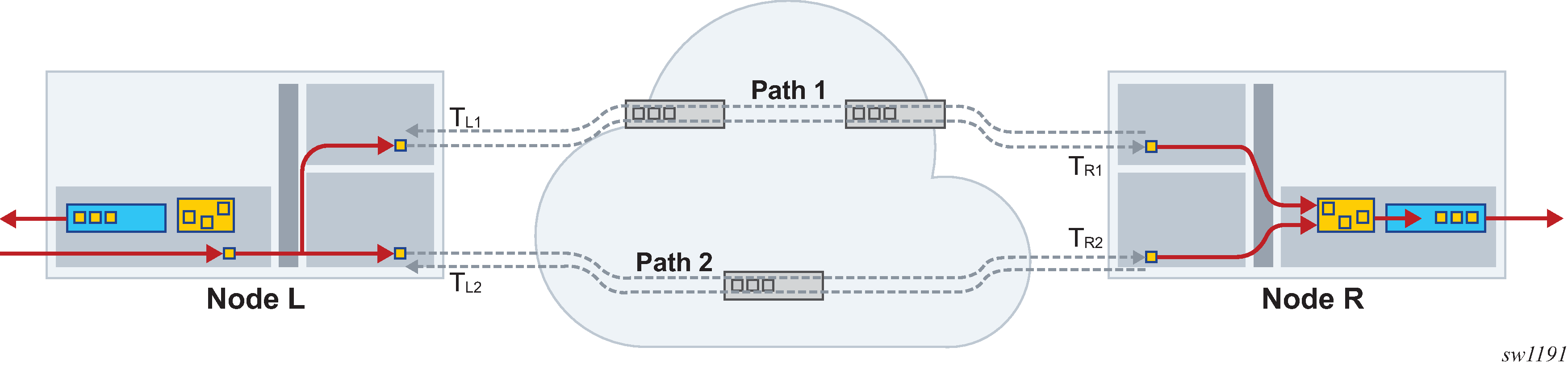
Network latency may be different for each path between the 7705 SAR nodes at each end. Path 1 can be different from Path 2 but both directions of each path must be symmetrical. To achieve symmetrical TDM service, each path is based on hop-by-hop strict LSPs; Fast Reroute (FRR) is not supported.
The configuration for the TDM service is the same at both the egress and ingress 7705 SAR nodes. The duplicated packets arrive over two different paths and are sent to the associated TDM adapter card. The packets are first processed through the new combiner for each TDM service. The combiner then feeds only a single copy of each packet to the jitter buffer while discarding unneeded packets.
ADC is mandatory as part of the symmetrical TDM service configuration. ADC analysis and adjustment are based on the traffic egressing the combiner. Jitter buffer overruns and underruns may still occur and result in service restarts, which is normal operation.
Combiner Operation
On startup, the combiner waits for traffic from the configured paths to be sent.
The all-paths-active state on the Cpipe is achieved when traffic is received from the configured paths and the combiner is able to compensate for the differential delay.
The spoke SDP path activity state for active-multipath (all-paths-active, not-all-paths-active, initialization, or down) can be viewed using CLI show commands or SNMP commands.
Access Ingress Fabric Shaping
If the destination-mode fabric profile is configured at access ingress, the multipoint destination shaper of the destination-mode fabric profile is used for shaping the traffic. For more information on fabric shaping, refer to the 7705 SAR Quality of Service Guide.
Cpipe Network Latency Measurement
Network latency measurement can be enabled at the service level on a Cpipe in order to record and display data on minimum, current, and maximum latency values. The feature is configured using the config>service>cpipe>network-latency-measurement command. The feature is enabled independently of AMP and ADC. If AMP is enabled, the end-to-end latency is measured on all configured paths.
If AMP is enabled, the operator must configure a jitter buffer size large enough to deal with worse-case jitter scenarios and the differential latency between the paths. The configured jitter buffer size is recommended to be equal to 2 x (maximum jitter of any path + maximum differential delay between paths). The network latency measurement function is useful in this case because having real-time data on the latency of each path helps to configure the jitter buffer size.
If network latency measurement is enabled, regular Cpipe packets are enhanced to include a proprietary 8-byte timestamp in every packet that is sent over the service. These timestamps are based on the router's internal time clock that is driven by PTP or GNSS. At the far-end router, the Cpipe packets are timestamped on arrival based on the router’s time clock that is also driven by PTP or GNSS. The end-to-end latency calculation can then be made, over 1024 packet windows, for the Cpipe packets sent over the service path.
The network latency measurement configuration (enabled or disabled) must be the same on all segments of the service, including the end nodes; otherwise, the unconfigured path does not come up and ‟Network Latency Mismatch” is displayed for each spoke SDP. Only end-to-end latency measurements are displayed, not segment-by-segment. The service must be shut down before the service configuration can be changed.
This feature is supported on any Cpipe, that is, a single-path Cpipe, a Cpipe with PW redundancy, or a Cpipe with AMP. In each case, the measured latencies for every configured path are displayed, so there is a single set of latencies for a single-path Cpipe and up to four sets of latencies for a Cpipe with PW redundancy and a Cpipe with AMP. After a no shutdown command, all latencies are initialized to zero and updated every 1024 packets. Any latencies that remain at zero are displayed as ‟N/A”.
A display of "N/A" could be caused by no traffic being received over the path or no timestamp being enabled at the near end, far end, or both ends. Otherwise, the most recent update is displayed.
The maximum latency that can be measured is 34.3 seconds. For any latency above 34.3 seconds, the current latency is displayed as "Too High". If there is a clocking issue that results in a situation where the far-end timestamp is earlier than the near-end timestamp, the latency is negative. In this case, the current latency is displayed as "Too Low". In either case, the minimum and maximum latencies are not updated, so the most recent minimum and maximum values are displayed.
VC switching supports latency measurements but does not support AMP. Inter-chassis backup (ICB) does not support latency measurements but the command is not blocked from the user in the CLI.
Latency measurements are supported on network interfaces on adapter cards and platforms that support a real-time clock. This includes all Ethernet adapter cards and the 7705 SAR-A, 7705 SAR-M, and 7705 SAR-X. On the 7705 SAR-A, 7705 SAR-M, and 7705 SAR-X, the network port can also be based on PPP/MLPPP.
The measured latencies for the Cpipe service can be displayed under the tools menu using the tools>dump>service>id>network-latency-measurement command. These measured latencies cannot be displayed using SNMP. See ‟Tools Dump Commands” in the 7705 SAR OAM and Diagnostics Guide for more information.
RTP Header
For all circuit emulation channels, the RTP in the header is optional (as per RFC 5086). When enabled for absolute mode operation, an RTP header is inserted in the MPLS frame upon transmit. Absolute mode is defined in RFC 5086 and means that the ingress PE will set timestamps using the clock recovered from the incoming TDM circuit. When an MPLS frame is received, the RTP header is ignored. The RTP header mode is for TDM PW interoperability purposes only and should be enabled when the other device requires an RTP header.
RTP cannot be enabled if asymmetric delay control is enabled.
Control Word
The control word is mandatory for SAToP and CESoPSN. The bit structure is shown in Control Word Bit Structure. Control Word Bit Descriptions describes the bit fields. See Pseudowire Control Word for more information.
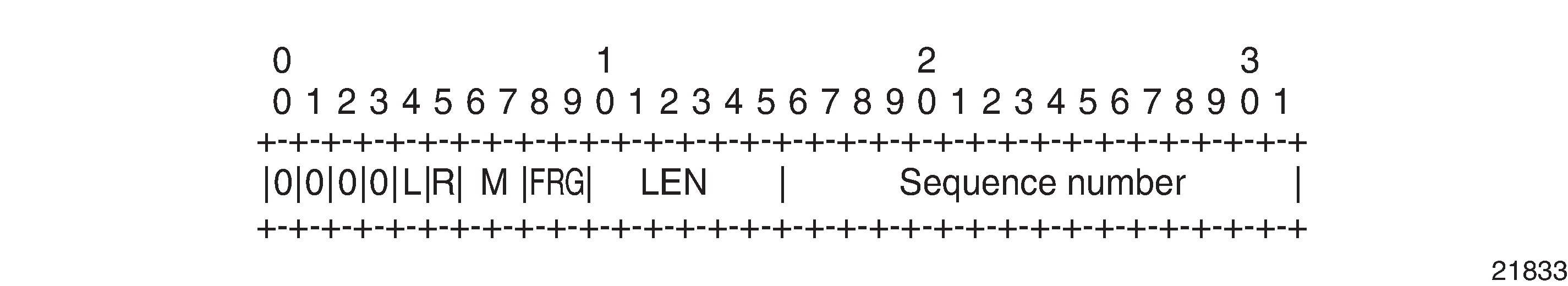
Bit |
Description |
|---|---|
Bits 0 to 3 |
The use of bits 0 to 3 is described in RFC 4385. These bits are set to 0 unless they are being used to indicate the start of an Associated Channel Header (ACH) for the purposes of VCCV. |
L (Local TDM Failure) |
The L bit is set to 1 if an abnormal condition of the attachment circuit such as LOS, LOF, or AIS has been detected and the TDM data carried in the payload is invalid. The L bit is cleared (set back to 0) when fault is rectified. |
R (Remote Loss of Frames indication) |
The R bit is set to 1 if the local CE-bound interworking function (IWF) is in the packet loss state and cleared (reset to 0) after the local CE-bound IWF is no longer in the packet loss state. |
M (Modifier) |
The M bits are a 2-bit modifier field. For SAToP, M is set to 00 as per RFC 4553. For CESoPSN, M is set according to RFC 5086, summarized as follows:
|
FRG |
The FRG bits in the CESoPSN control word are set to 00. |
LEN |
The LEN bits (bits 10 to 15) carry the length of the CESoPSN packet (defined as the size of the CESoPSN header plus the payload size) if it is less than 64 bytes, and set to 0 otherwise. |
Sequence number |
The sequence number is used to provide the common PW sequencing function as well as detection of lost packets. |
Transparent SDH/SONET Over Packet (TSoP)
Transparent SDH/SONET over Packet (TSoP) is a method for transporting clear channel OC3/STM1 or clear channel OC12/STM4 traffic over a packet network using OC3/STM1 TSoP SFPs and OC12/STM4 TSoP SFPs. With TSoP, the entire signal is encapsulated in a pseudowire and transported over the network to a single destination, which simplifies operation. TSoP is modeled after the SAToP method for pseudowire transport of DS1, E1, DS3, or E3 circuits (RFC 4553).
TSoP SFPs are inserted into Ethernet SFP ports, and the 7705 SAR treats them as standard Ethernet SFPs. To set up the TSoP service, an Epipe must be created across the network connecting two OC3/STM1 TSoP SFPs or two OC12/STM4 TSoP SFPs. The TSoP SFPs implement DCR for service clock delivery. Both nodes must be synchronized against a common clock for DCR.
TSoP SFPs are supported on the 7705 SAR-8 Shelf V2 and 7705 SAR-18 on the following adapter cards:
8-port Gigabit Ethernet Adapter card
6-port Ethernet 10Gbps Adapter card
10-port 1GigE/1-port 10GigE X-Adapter card (7705 SAR-18 only)
Each adapter card supports two OC3/STM1 or OC12/STM4 TSoP SFPs. A maximum of 16 TSoP SFPs are supported on the 7705 SAR-8 Shelf V2 or 7705 SAR-18.
Error Situations
The CE-bound interworking function (IWF) uses the sequence numbers in the control word to detect lost and incorrectly ordered packets. Incorrectly ordered packets that cannot be reordered are discarded.
For unstructured CES, the payload of received packets with the L bit set is replaced with an all-ones pattern. For structured CES, the payload of received packets with the L bit set is replaced with an all-ones or a user-configurable bit pattern. This is configured using the idle-payload-fill command. For structured CES with CAS, the signaling bits are replaced with an all-ones or a user-configurable bit pattern. This is configured using the idle-signal-fill command. See the 7705 SAR Interface Configuration Guide for more information.
All circuit emulation services can have a status of up, loss of packets (LOP) or admin down, and any jitter buffer overruns or underruns are logged.
Ethernet VLL (Epipe) Services
This section provides information about the Epipe service.
Topics in this section include:
Epipe configuration information is found under the following topics:
See Service Support for information about the adapter cards and chassis that support Ethernet VLL services.
Epipe Service Overview
An Ethernet pseudowire (PW) is used to carry Ethernet/802.3 protocol data units (PDUs) over an MPLS or IP network, allowing service providers to offer emulated Ethernet services over existing MPLS or IP networks. For the 7705 SAR, Ethernet emulation is a point-to-point service.
The 7705 SAR uses Ethernet VLLs to carry Ethernet traffic from various sources at a site, including traffic such as e911 locators, power supply probes, and HSPA-dedicated interfaces. Native Ethernet bridging is not supported.
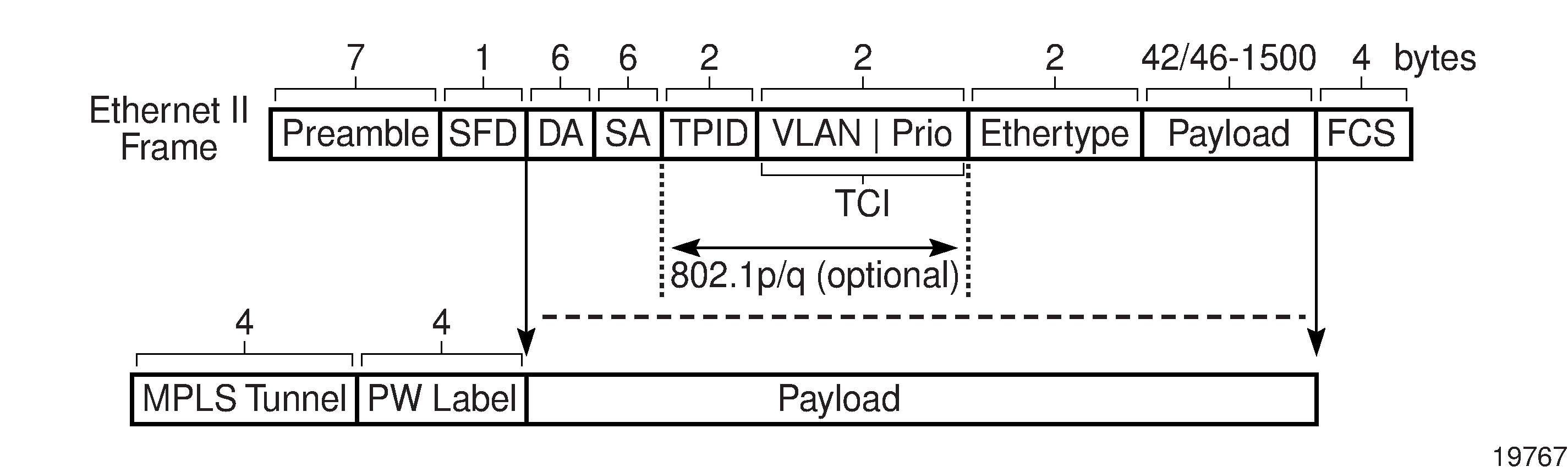
An MPLS Epipe service is the Nokia implementation of an Ethernet VLL based on the IETF RFC 4448, Encapsulation Methods for Transport of Ethernet over MPLS Networks.
Ethernet VLL Frame with MPLS Encapsulation shows a typical Ethernet VLL frame together with its MPLS tunnel encapsulation.
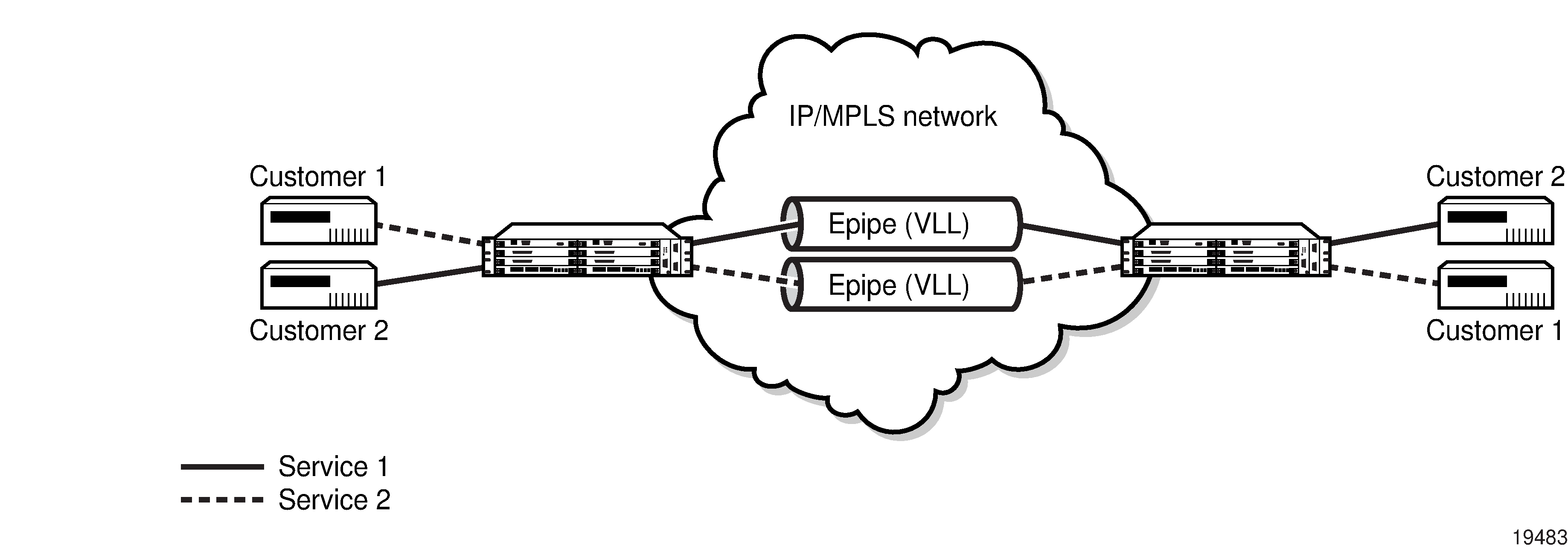
An Epipe service is a Layer 2 point-to-point service where the customer data is encapsulated and transported across a service provider’s MPLS or IP network. Epipe Service shows a typical Epipe service. An Epipe service is completely transparent to the subscriber’s data and protocols. Like other PW VLL services, Epipe service functions as a non-learning Ethernet bridge. A distributed Epipe service consists of a SAP and an SDP pair, where one SDP is on same router as the SAP, and the second SDP is on the far-end router.
Each SAP configuration includes a specific port on which service traffic enters the 7705 SAR from the customer side (also called the access side). Each port is configured with an encapsulation type (SAP encapsulation). Thus, a whole Ethernet port can be bound to a single service (that is, the whole Ethernet port is configured as a SAP), or if a port is configured for IEEE 802.1Q or 802.1ad encapsulation (referred to as dot1q or qinq, respectively), then a unique encapsulation value (ID) must be specified.
Ethernet Access Egress Queuing and Scheduling
Ethernet access egress queuing and scheduling is very similar to the Ethernet access ingress behavior. Once the Ethernet pseudowire is terminated, traffic is mapped to up to eight different forwarding classes per SAP. Mapping traffic to different forwarding classes is performed based on the EXP bit settings of the received Ethernet pseudowire.
For more information about Ethernet access egress queuing and scheduling, see the 7705 SAR Quality of Service Guide.
Ethernet SAP-to-SAP
Ethernet VLLs can be configured with both endpoints (SAPs) on the same 7705 SAR. This is referred to as Ethernet SAP-to-SAP or local Ethernet service. Ethernet SAP-to-SAP provides local Ethernet switching between two Ethernet endpoints on the 7705 SAR.
An Ethernet SAP-to-SAP connection is set up on the 7705 SAR and a pseudowire is configured between the two endpoints.
When the port encapsulation is null, there is no change to the VLAN tags on the ingress and egress frame headers, if VLAN tags are present.
When the port encapsulation is dot1q, the VLAN tag is removed from the ingress frame header and a new VLAN tag is inserted into the egress frame header. No VLAN tag is inserted into the egress frame header if the SAP has a VLAN ID of 0.
When the port encapsulation is qinq, the VLAN tags are removed from the ingress frame header and a new set of outer and inner VLAN tags are inserted in the egress frame header. No VLAN tags are inserted in the egress frame if the SAP has a VLAN ID of 0 or VLAN IDs of 0.*. SAP 0.0 is not a valid combination.
In addition, the 7705 SAR-M can use a SAP-to-SAP Ethernet PW to provide an Ethernet-to-ATM interworking service. This is done by having one SAP on an Ethernet port and the other SAP on an ATM port or IMA bundle. Encapsulation options are specified in RFC 2684, Multiprotocol Encapsulation over ATM Adaptation Layer 5. The Ethernet-to-ATM interworking service can be used to support:
interworking of legacy bridged ATM traffic to Ethernet
transport of Ethernet traffic over an existing ATM network
See Configuring ATM Encapsulation Under Epipe Service (7705 SAR-M only) for more information.
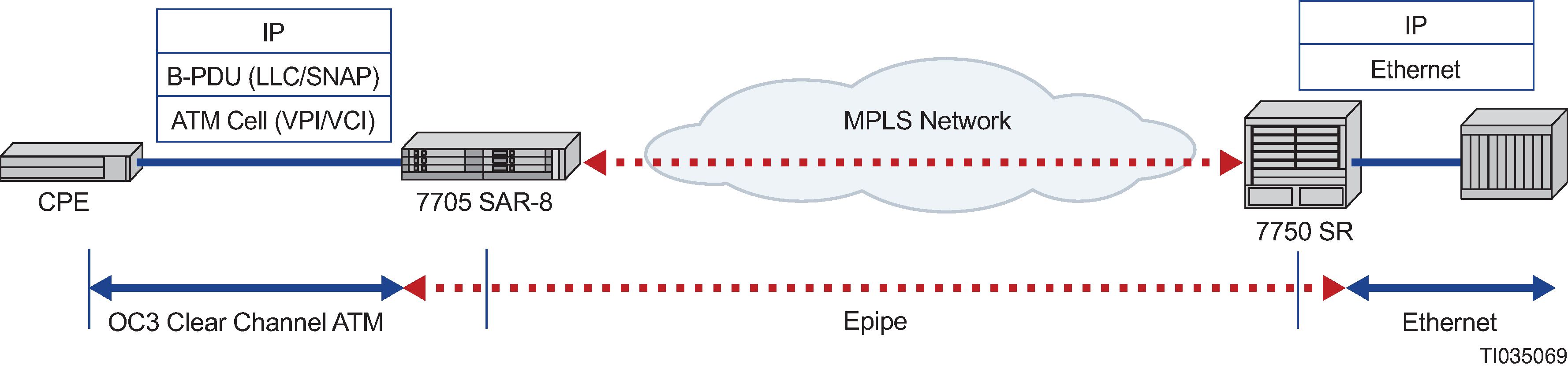
Epipe with ATM SAPs
The 7705 SAR supports Epipe with ATM SAPs over an Ethernet SDP; this feature is available on the 7705 SAR-8 Shelf V2 or 7705 SAR-18. IP interworking is between an OC3 clear channel ATM over a 10-Gigabit or Gigabit Ethernet connection through an MPLS network. The SAP connection is from an ATM VC configured on a 4-port OC3/STM1 Clear Channel Adapter card. The Ethernet SDP connection is from a 6-port Ethernet 10Gbps Adapter card. The ATM SAP format can only be UNI. BPDU with LLC/SNAP is used as specified in RFC 2684.
Epipe Network Configuration with ATM SAP shows an example of an Epipe network configuration with an ATM SAP on a 7705 SAR-8 Shelf V2. For a CLI configuration example, see Configuring Epipe with ATM SAP.
MEF 8
The 7705 SAR supports MEF 8 as defined in the Implementation Agreement for the Emulation of PDH Circuits over Metro Ethernet Networks. Support for the MEF 8 standard allows both structured and unstructured emulation of TDM services across Epipes, also known as Circuit Emulation Services over Ethernet (CESoETH). The MEF 8 feature enables the 7705 SAR to interoperate with equipment that does not support MPLS-based Cpipes but does support MEF 8 Epipes.
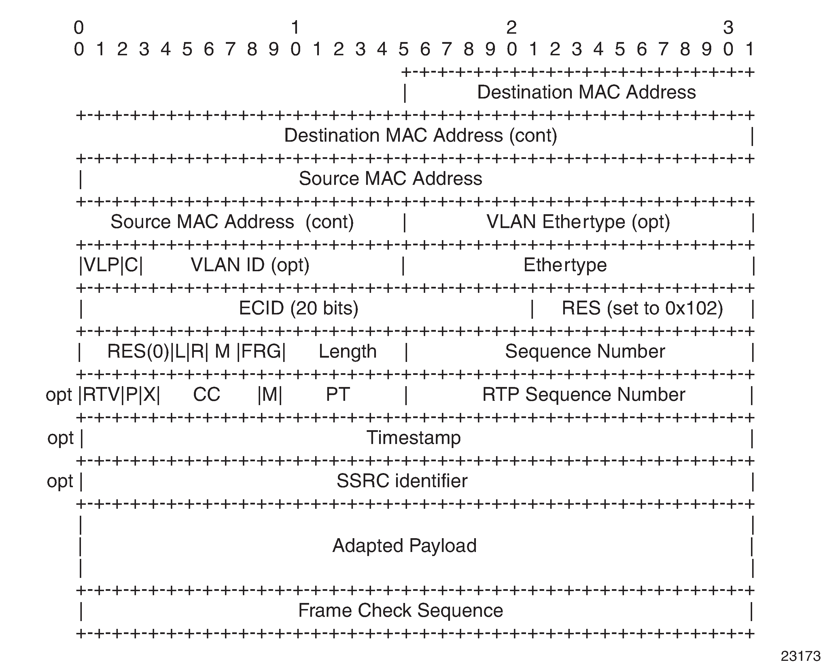
CESoETH Encapsulation shows an Ethernet-encapsulated TDM circuit. See TDM PW Encapsulation for complete information about TDM PW encapsulation.
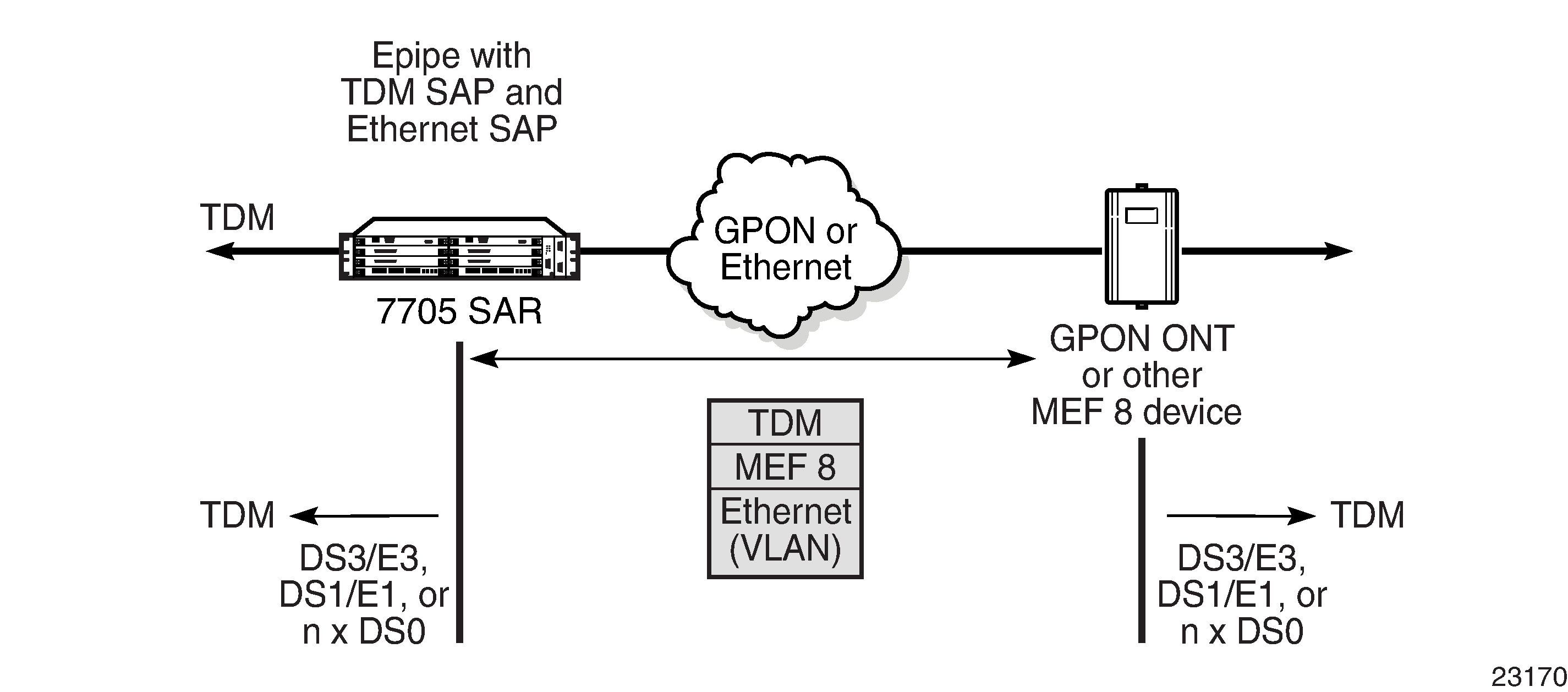
The 7705 SAR supports the following MEF 8 configuration scenarios:
TDM SAP to Ethernet SAP (see TDM SAP to Ethernet SAP)
A GPON ONT or other MEF 8-only device is used to encapsulate TDM over a GPON or Ethernet network, and the 7705 SAR is used to terminate the MEF 8.
TDM SAP to spoke SDP (see TDM SAP to Spoke SDP)
A GPON ONT or other MEF 8-only device is used to encapsulate TDM over an MPLS network, and the 7705 SAR is used to terminate both the LSP and MEF 8.
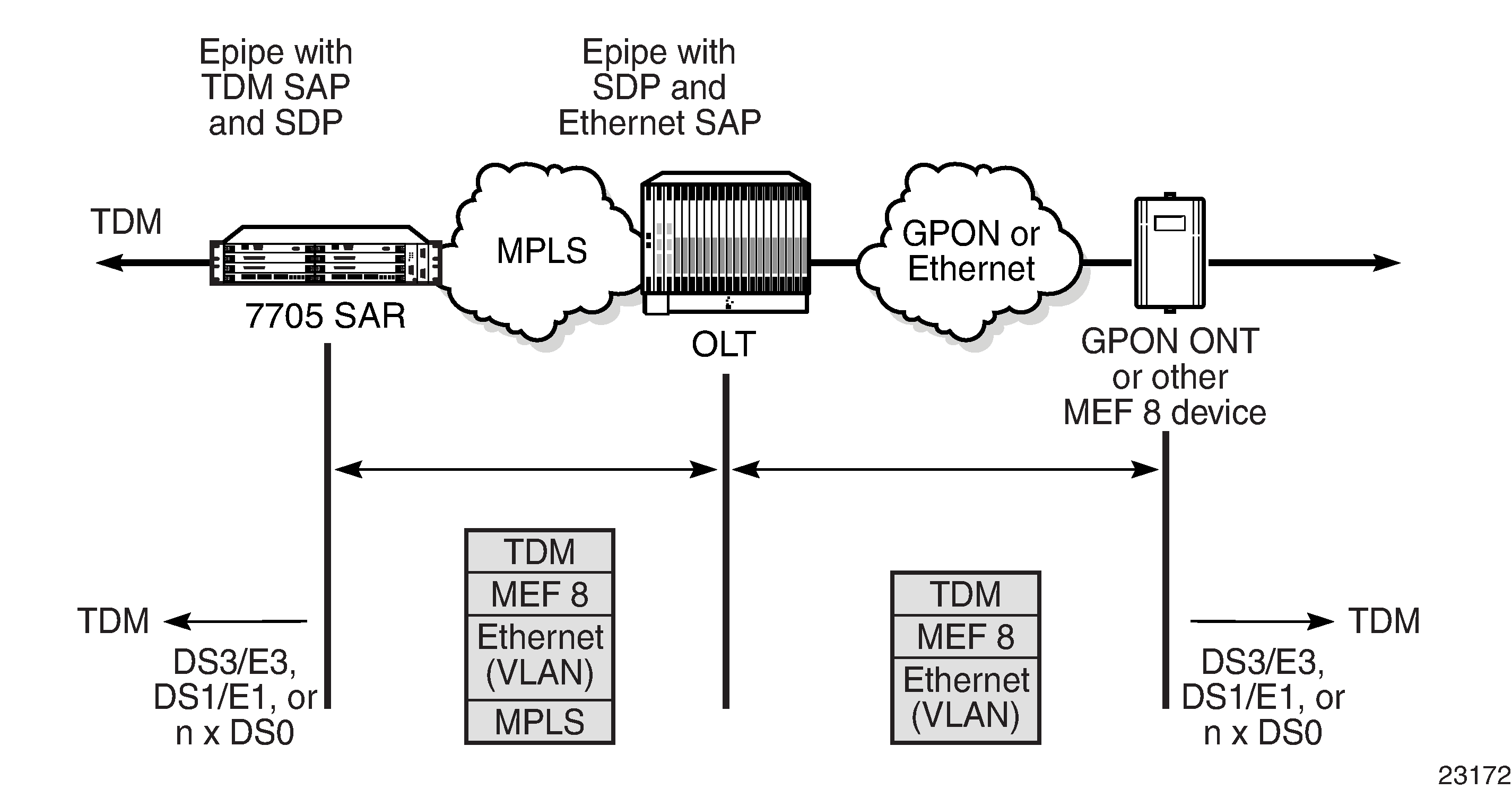
The following table shows the platforms, adapter cards, and modules that support MEF 8.
TDM SAP to Ethernet SAP |
TDM SAP to Ethernet via Epipe Spoke SDP |
|||
|---|---|---|---|---|
Structured1 |
Unstructured |
Structured1 |
Unstructured |
|
7705 SAR-M All T1/E1 ports |
✓ |
✓2 |
✓ |
✓2 |
7705 SAR-A All T1/E1 ports |
✓ |
✓2 |
✓ |
✓2 |
7705 SAR-X All T1/E1 ports |
✓ |
✓2 |
✓ |
✓2 |
16-port T1/E1 ASAP Adapter card |
✓ |
✓2 |
✓ |
✓2 |
32-port T1/E1 ASAP Adapter card |
✓ |
✓2 |
✓ |
✓2 |
2-port OC3/STM1 Channelized Adapter card |
✓ |
✓3 |
✓ |
✓3 |
4-port DS3/E3 Adapter card |
✓ |
✓4 |
✓ |
✓4 |
4-port OC3/STM1 / 1-port OC12/STM4 Adapter card |
✓5 |
✓5 |
||
4-port T1/E1 and RS-232 Combination module All T1/E1 ports |
✓ |
✓2 |
✓ |
✓2 |
6-port E&M Adapter card |
✓ |
✓ |
||
6-port FXS Adapter card |
✓ |
✓ |
||
8-port FXO Adapter card |
✓ |
✓ |
||
12-port Serial Data Interface card, version 3 |
✓ |
✓ |
||
Notes:
Supported on n x DS0 channels with or without CAS
Supported on DS1/E1 ports
Supported on DS1/E1 channels and DS3/E3 channels
Supported on DS1/E1 channels and DS3/E3 ports
Supported on DS1/E1 channels
Epipe Service Modes
Epipe services support structured circuit emulation mode for nxDS0 and structured or unstructured circuit emulation mode for DS1, E1, DS3, and E3 as defined in the MEF 8 specification.
There are two methods for using MEF 8 to emulate TDM circuits over Ethernet using an Epipe:
TDM SAP-to-Ethernet SAP
TDM SAP-to-spoke SDP
Defining one TDM SAP and one Ethernet SAP is known as Circuit Emulation Services over Ethernet (CESoETH). The TDM SAP configured in the Epipe must include a local and remote Emulated Circuit Identifier (ECID) and a far-end destination MAC address. The TDM port’s MAC address is used as the source MAC address for the circuit.
TDM can also be encapsulated into Ethernet which is then encapsulated in MPLS (or GRE). This method is known as Circuit Emulation Services over Ethernet over MPLS (CESoETHoMPLS). CESoETHoMPLS is configured with an Epipe with a TDM SAP and a spoke SDP. The TDM SAP configured in the Epipe must include a local and remote ECID and a far-end destination MAC address. The TDM port’s MAC address is used as the source MAC address for the circuit.
The 7705 SAR supports unicast MAC addresses and non-IEEE-reserved group multicast MAC addresses.
The TDM SAP’s framing and CAS settings determine the MEF 8 circuit emulation mode. If the TDM port is framed, MEF 8 is in structured mode. If the TDM port is unframed, MEF 8 is in unstructured mode. If the TDM SAP is configured with CAS enabled, MEF 8 is in structured mode with CAS. See Unstructured, Structured DS1/E1 CES without CAS, and Structured T1/E1 CES with CAS for more information about circuit emulation modes.
Adaptive clock recovery (ACR) is supported for MEF 8 in structured or unstructured mode on the following platforms and adapter cards:
7705 SAR-A (variant with T1/E1 ports)
7705 SAR-M (variants with T1/E1 ports)
7705 SAR-X (T1/E1 ports)
16-port T1/E1 ASAP Adapter card
32-port T1/E1 ASAP Adapter card
For more information about ACR, see the 7705 SAR Basic System Configuration Guide, ‟Adaptive Clock Recovery (ACR)”.
Differential clock recovery (DCR) is supported for MEF 8 in structured or unstructured mode on the following platforms, adapter cards, and modules:
7705 SAR-A (variant with T1/E1 ports)
7705 SAR-M (variants with T1/E1 ports)
7705 SAR-X (T1/E1 ports)
16-port T1/E1 ASAP Adapter card
32-port T1/E1 ASAP Adapter card
4-port OC3/STM1 / 1-port OC12/STM4 Adapter card (DS1/E1 channels)
4-port DS3/E3 Adapter card (clear channel DS3/E3 ports and DS1/E1 channels on channelized DS3 ports (E3 ports cannot be channelized)); DCR on DS1/E1 channels is supported only on the first three ports of the card
T1/E1 ports of the 4-port T1/E1 and RS-232 Combination module
To enable DCR, the network must have a common clock between the two terminating SAPs or SAP/spoke SDP using MEF 8. In each direction, the service clock is compared to the common clock and the difference is encoded into the RTP header in the TDM PW overhead. At the other end of the network, the original service clock is reproduced by comparing the common clock to the frequency difference in the RTP header.
For more information about DCR, see the 7705 SAR Basic System Configuration Guide, ‟Differential Clock Recovery (DCR)”.
Ethernet OAM
Ethernet VLL service supports Ethernet OAM functions for ETH-CFM according to the 802.1ag and Y.1731 standards, for Y.1731 Performance Monitoring, and for EFM OAM according to the 802.3ah standard. For more information, see ETH-CFM (802.1ag and Y.1731), and see the ‟Ethernet OAM” section in the 7705 SAR Interface Configuration Guide, and the ‟Ethernet OAM Capabilities” section in the 7705 SAR OAM and Diagnostics Guide.
Ethernet ports in access or network mode also support CFM loopback message (LBM) frames for Layer 1 and Layer 2 OAM tests on unlabeled ports. For more information, see the ‟Ethernet OAM” section in the 7705 SAR Interface Configuration Guide.
Control Word
Ethernet (Epipe) services support an optional control word, with the exception of MEF 8 (CESoETH) services for which the control word is mandatory (for information about the MEF 8 service control word, see the Control Word section in Circuit Emulation Parameters and Options).
If the Epipe service control word is enabled, it is set to all zeros and ignored on egress.
See Pseudowire Control Word for more information.
MTU
Network-facing Ethernet ports must support a larger MTU than access-facing Ethernet ports to account for the pseudowire headers that are added to the access Ethernet frames.
As an example, the following list gives the worst-case MTU sizes for Ethernet VLLs over Ethernet ports under various configurations, where the worst case is the largest MTU size required to carry a standard payload (1500 bytes):
Access, null mode: 1514 bytes
Access, dot1q mode: 1518 bytes
Access, qinq mode: 1522 bytes
Network, null mode: 1572 bytes
Network, dot1q mode: 1572 bytes
Raw and Tagged Modes
An Ethernet PW operates in one of two modes: raw or tagged. Raw and tagged modes relate to the way the router handles VLAN tags embedded in the header of an Ethernet frame. Both modes are supported by the 7705 SAR.
Raw and tagged modes are configured using the vc-type {ether | vlan} parameter under the spoke-sdp command. To configure raw mode, choose the ether option; to configure tagged mode, choose vlan.
VLAN tags can provide service-delimiting information about a frame. Service-delimiting means that information in the tag affects the forwarding decisions that are made to route the packet. The port connected to the attachment circuit (AC) can be configured for null, dot1q, or qinq operation. When the port is configured for null, the 7705 SAR treats any attached tag received at the SAP (from the AC) as not service-delimiting; when configured for dot1q or qinq, received tags are service-delimiting.
Raw Mode
In raw mode, VLAN tags are not service-delimiting (that is, the port is set to null and the tags do not affect frame forwarding decisions) and are forwarded over the Epipe as part of the payload.
If a service-delimiting tag arrives from the ingress AC (that is, the port is set to dot1q or qinq and a tag is received), the tags are removed (popped) from the payload before the Ethernet frame gets switched over the PSN via the Epipe.
In raw mode, all traffic from the ingress port gets switched to the same endpoint. However, if the MTU (or configured size) of the tunnel is exceeded then service is affected because the frame is dropped.
In raw mode, when the 7705 SAR detects a failure on the Ethernet ingress port or the port is administratively disabled, the 7705 SAR sends a PW status notification message to the remote router.
Tagged Mode
In tagged mode, every frame sent on the Ethernet PW has a service-delimiting VLAN tag. If the frame received by the 7705 SAR from the attachment circuit (AC) does not have a service-delimiting VLAN tag, then the 7705 SAR inserts (pushes) a VLAN tag into the frame header before sending the frame to the SDP and the PW. If the frame received from the AC has a service-delimiting VLAN tag, the tag is replaced.
In tagged mode, when the 7705 SAR detects a failure on the Ethernet physical port or the port is administratively disabled, the 7705 SAR sends a PW status notification message for all PWs associated with the port.
VLAN Translation
VLAN ID translation is supported, as appropriate. VLAN Tagging Examples (Epipe) (see Tagging Rules for Epipe) shows the VLAN ID translation operation for the various packet types. The payload part of the packet is shown in parentheses.
The operations to add, strip (remove), or forward the VLAN headers are performed based on the encapsulation type at the ingress of the attachment circuit (the SAP), in the network, and at the egress circuit.
Tagging Rules for Epipe
Ingress SAP Tagging Rules and Egress SAP Tagging Rules show the general tagging rules for combinations of interface port type (null, dot1q, or qinq) and Epipe type (Ethernet or VLAN) for SAP ingress and SAP egress directions.
An AC (attachment circuit, ingress or egress) can be configured for one of the following encapsulation types:
null
dot1q
qinq
Single-tagged Ethernet packets with VLAN ID set to 0 are handled in the same way as other tagged packets.
For Ethernet VLL SAP-to-SAP with a VLAN SAP, the dot1p header is not popped at ingress. Instead, it is preserved across the ingress and egress ports to ensure dot1p transparency. Dot1q bits are overwritten with configured VLAN information at egress. If there is a matching non-default QoS policy applied at egress, the dot1p bits are re-marked accordingly.
Ingress SAP Type 1 |
VC Type (Epipe) |
|
|---|---|---|
Raw (Ethernet) |
Tagged (VLAN) |
|
Null |
No operation |
Push (VC tag) |
Dot1q |
Pop (outer tag) |
Pop (outer tag) Push (VC tag) 2 |
QinQ |
Pop (outer tag) |
Pop (outer tag) Push (VC tag) |
Notes:
Ingress SAP type is configured at the port level.
If the VC tag is not set, the original tag is preserved. The VC tag is set on the spoke SDP, using the vlan-vc-tag command.
Egress SAP Type 1 |
VC Type (Epipe) |
|
|---|---|---|
Raw (Ethernet) |
Tagged (VLAN) |
|
Null |
No operation |
Pop (VC tag) |
Dot1q |
Push (SAP tag) 2 |
Pop (VC tag) Push (SAP tag)3 |
QinQ |
Push (SAP tags) |
Pop (VC tag) Push (SAP tags) |
Notes:
Egress SAP type is configured at the port level.
If the SAP tag is 0, no VLAN tag is pushed.
If the SAP tag is 0, only the pop operation is performed.
VLAN Tagging Examples (Epipe) shows several examples of how VLAN tags are translated as they flow from ingress to egress. The ingress or egress point can be a SAP or an SDP. For a SAP, encapsulation can be null, dot1q, or qinq; for an SDP, encapsulation (vc-type) can be ether raw or VLAN (tagged). When the SAP encapsulation is dot1q or qinq, outer and inner tags are used.
-
the SAP VLAN tag always delimits the ingress traffic, regardless of the Ethernet VLL type (raw or tagged)
-
untagged frames are dropped at the SAP ingress. That is, only the frames with an outer VLAN tag that matches the SAP VLAN tag are forwarded. The exception to this case occurs when the VLAN tag = 0. When a SAP is configured with VLAN ID = 0, any received untagged packets are processed.
|
Configuration Settings |
||||
|---|---|---|---|---|
|
Rx (Ing)/ Tx (Egr) |
SAP/ SDP |
Encap. |
SAP VLAN Tag |
|
|
Outer |
Inner |
|||
|
Rx Tx |
SAP SAP |
Null Null |
N/A N/A |
N/A N/A |
|
Result: Untagged, single-, and double-tagged frames are accepted. On egress, all frames are transmitted untouched. |
||||
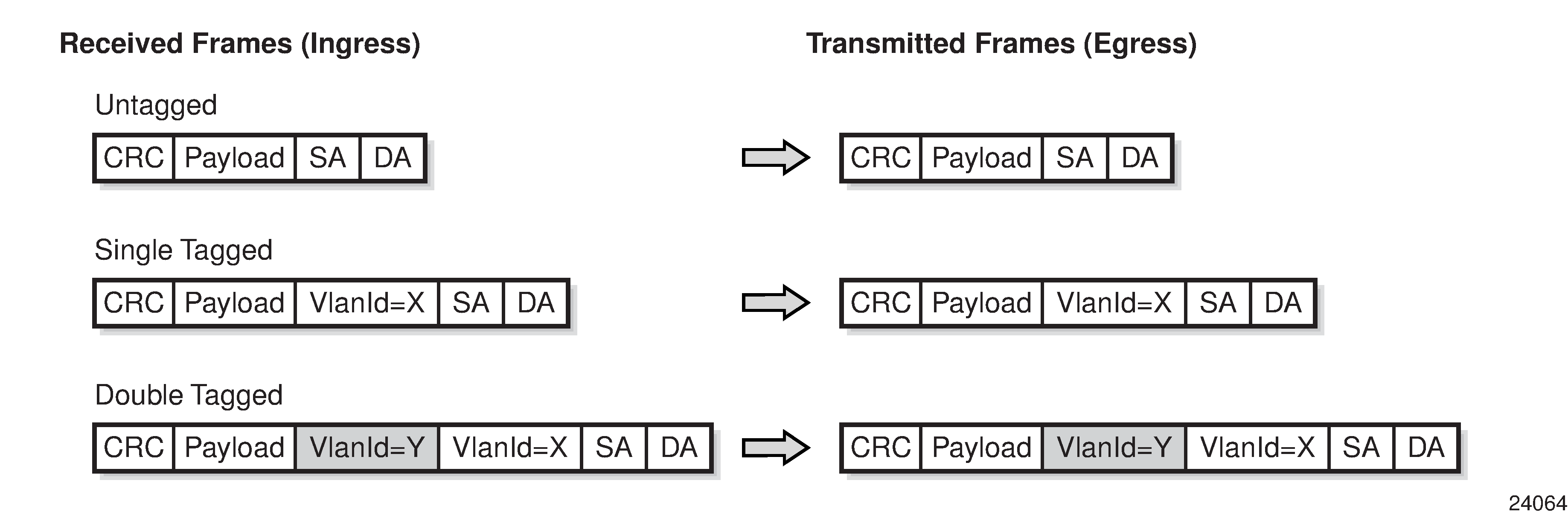
|
||||
|
Rx Tx |
SAP SAP |
Dot1q Null |
252 N/A |
N/A N/A |
|
Result: Single- and double-tagged frames are accepted if the outermost VLAN ID matches. On egress, the outermost VLAN tag is popped. |
||||
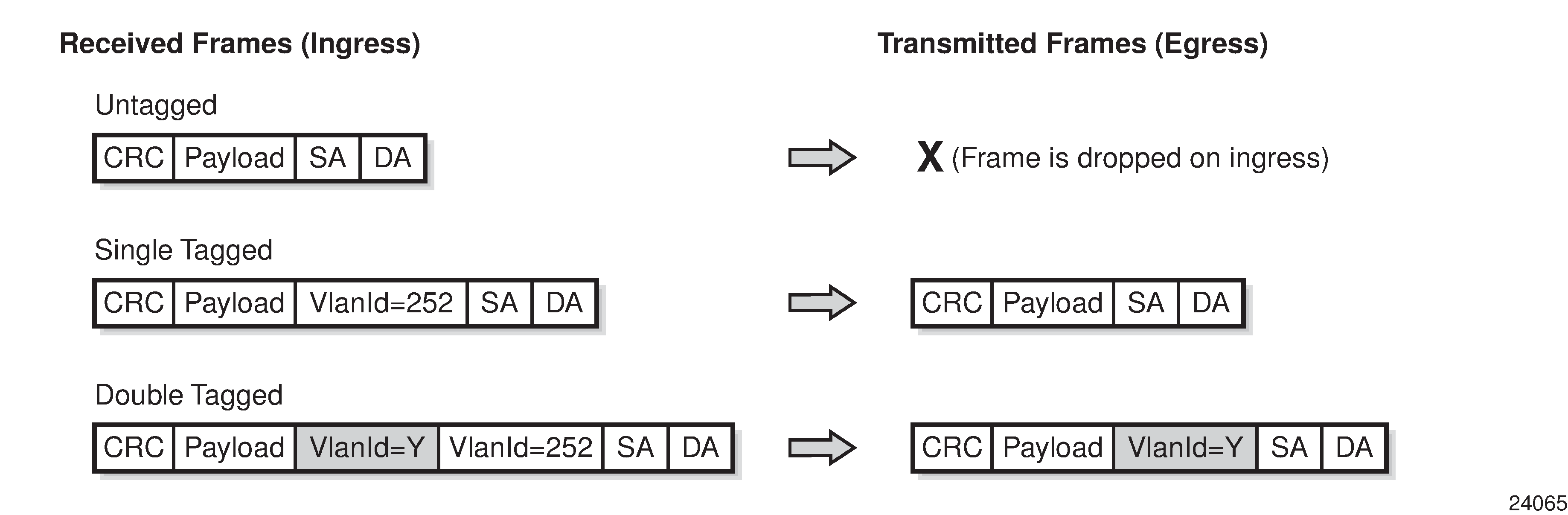
|
||||
|
Rx Tx |
SAP SAP |
QinQ Dot1q |
525 789 |
353 N/A |
|
Result: Double-tagged frames are accepted if the outer/inner VLAN ID matches. On egress, the outer VLAN tag is popped and the inner VLAN tag is swapped. |
||||
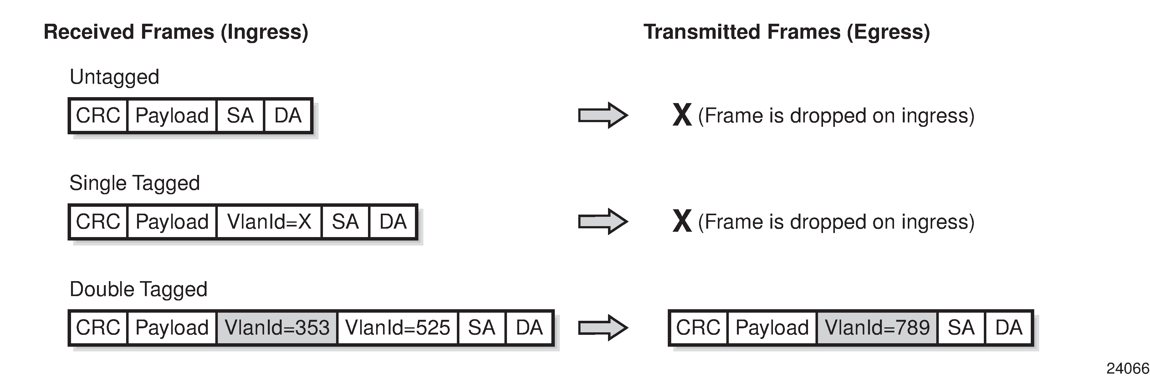
|
||||
|
Rx Tx |
SAP SDP |
QinQ VLAN |
525 456 |
353 N/A |
|
Result: Double-tagged frames are accepted if the outer/inner VLAN ID matches. On egress, the outer VLAN tag is popped and the inner VLAN tag is swapped. |
||||

|
||||
|
Rx Tx |
SDP SAP |
Ether QinQ |
N/A 123 |
N/A 654 |
|
Result: Untagged, single-, and double-tagged frames are accepted. On egress, a double-push (outer and inner) is performed. |
||||
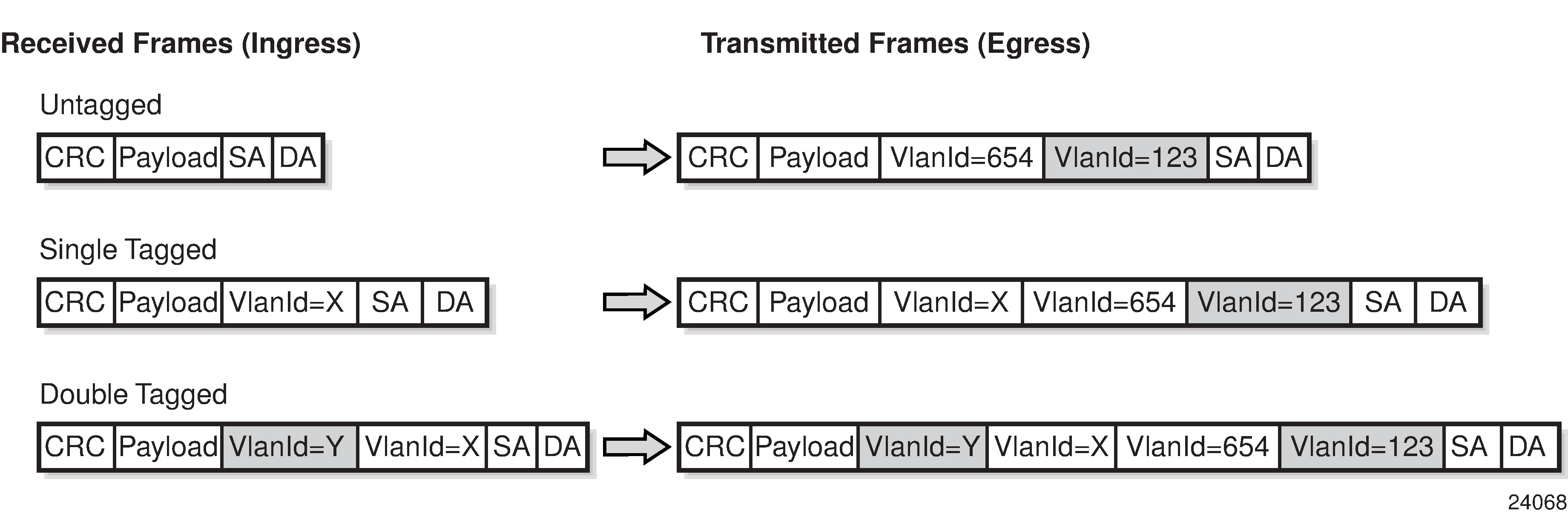
|
||||
|
Rx Tx |
SAP SDP |
Dot1q VLAN |
Default (*) 741 |
N/A N/A |
|
Result: Untagged, single-, and double-tagged frames are accepted. On egress, a push is performed. |
||||
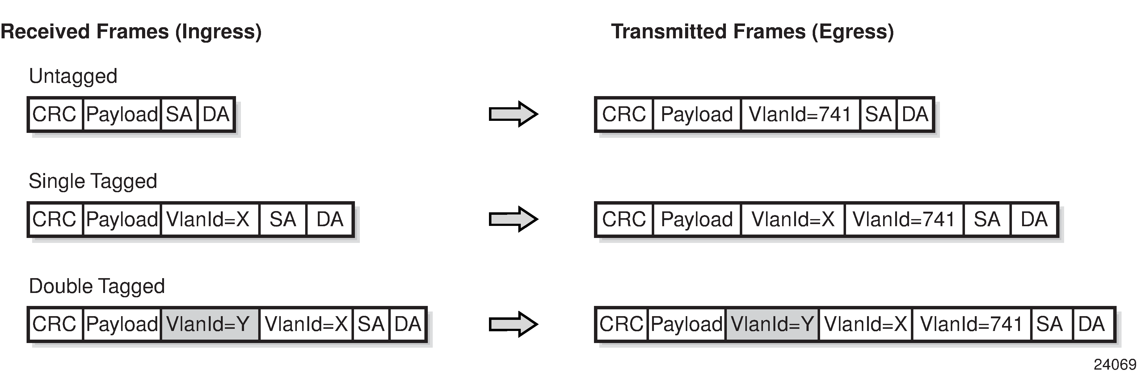
|
||||
|
Rx Tx |
SAP SDP |
QinQ VLAN |
852 963 |
0 N/A |
|
Result: Single- and double-tagged frames are accepted if the outermost VLAN ID matches. On egress, the outermost VLAN tag is swapped. |
||||
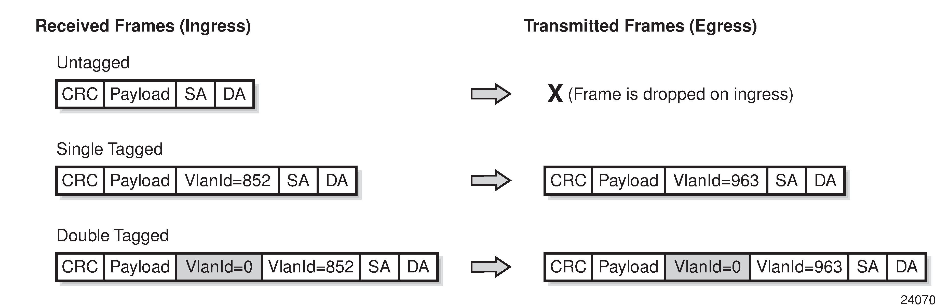
|
||||
|
Rx Tx |
SAP SAP |
QinQ QinQ |
Default (*) Default (*) |
Default (*) Default (*) |
|
Result: Any double-tagged frames are accepted. On egress, all frames are transmitted untouched. |
||||
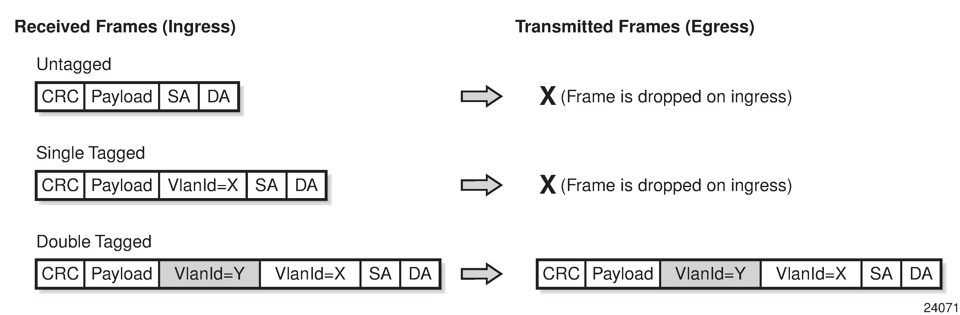
|
||||
IP Filters (Epipe)
IP filters are applied to Epipe SAPs in the ingress direction, as described below. For a full list of entities to which IP filters can be applied, see IP Filter Policies.
Ethernet pseudowires are generally used to transparently switch traffic across an MPLS network to the far end. However, in some cases, the traffic that is switched over the network, consuming valuable bandwidth, is just discarded at the other end of the pseudowire. As well, with the 7705 SAR expanding into areas such as vertical markets, and with local area networks being connected to the 7705 SAR Ethernet ports, an increasing amount of traffic must stay local and not pass through the MPLS network to the far end. By using IP filters at the access ingress, operators can determine what traffic is passed through the pseudowire and therefore use the network links more efficiently.
IP filters can also be used for security purposes, by allowing access only to designated services (for example, allowing email and FTP services while disallowing Telnet services) at the origin of the traffic.
IP filter policies specify either a forward or a drop action for packets, based on information specified in the match criteria. Within each filter policy, you can create entries that define matching criteria.
The same IP filter policy can be assigned to any entity (network interfaces, IP pseudowires, Ethernet pseudowires, IES, and VPRN services), all of which can be configured on the same adapter card. For example, a filter policy defined as ‟filter-5” can be assigned to multiple Epipe SAPs and, simultaneously, to network interfaces on the same adapter card.
A filter policy assigned to an entity on one adapter card can also be assigned to any entity on another adapter card. For example, a filter policy defined as ‟filter-2” can be assigned to an Epipe on an Ethernet Adapter card and to a network interface on another Ethernet Adapter card.
Assigning the same filter policy to different entities on a card counts as using one filter policy.
Configuration and assignment of filter policies is similar for network interfaces, IES management SAPs, Ethernet and IP pseudowire SAPs, VPRN and IES SAPs and spoke SDPs, and VPLS SAPs and SDPs (spoke and mesh). This guide describes the assignment of filter policies to SAPs and SDPs. See the 7705 SAR Router Configuration Guide, ‟Filter Policies”, for information about configuring filter policies and assigning them to network interfaces.
MPLS Entropy Label
For Cpipes, Epipes, and Ipipes, the router supports MPLS entropy labels as per RFC 6790. The entropy label provides greater granularity for load balancing on an LSR where load balancing is typically based on the MPLS label stack.
For more information, see the ‟MPLS Entropy Labels” section in the 7705 SAR MPLS Guide and to the ‟LAG and ECMP Hashing” section in the 7705 SAR Interface Configuration Guide.
Security Zones and Epipes
The 7705 SAR supports a number of mechanisms for node security, including Access Control Lists (ACLs), Network Address Translation (NAT), and stateful, zone-based firewalls. For information about ACLs, NAT, and firewalls, see the 7705 SAR Router Configuration Guide, ‟Configuring Security Parameters”.
NAT and firewall security configurations are both based on zones. Zones segment a network, making it easier to control and organize traffic. A zone consists of a group of Layer 2 endpoints or Layer 3 interfaces with common criteria, bundled together. Security policies, which define a set of rules that determine how NAT or firewall should direct traffic, can be applied to the entire zone or to multiple zones. Layer 3 zones support both NAT and firewall security policies. Layer 2 zones support only firewalls. To enable NAT or firewall functionality, security policy and profile parameters must be configured under the config>security context in the CLI, and a security zone must be configured under one or more of the following contexts:
config>router>zone
config>service>epipe>zone
config>service>vpls>zone
config>service>vprn>zone
config>service>ies>zone
Layer 2 and Layer 3 firewalls share system resources; that is, they share the maximum number of policies, profiles, and session ID space supported by the system.
A zone is created by adding at least one Layer 2 endpoint or Layer 3 interface to the zone configuration. Multiple zones can be created within each Layer 3 service or within the router context. Layer 2 services support only one zone. Layer 2 endpoints or Layer 3 interfaces from different services cannot be grouped into a single common zone. Security Zone Interfaces and Endpoints per Context lists the supported interfaces and endpoints that can be added to zones in each CLI context for NAT or firewall.
CLI Context |
Interface/Endpoint Type |
NAT |
Firewall |
|---|---|---|---|
Router |
Layer 3 |
✓ |
✓ |
Epipe |
SAP |
✓ |
|
Spoke-SDP termination |
✓ |
||
VPLS |
SAP |
✓ |
|
Spoke-SDP termination |
✓ |
||
Mesh SDP |
✓ |
||
EVPN |
|||
VPRN |
SAP |
✓ |
✓ |
Spoke-SDP termination |
✓ |
✓ |
|
IPSec private |
✓ |
✓ |
|
IPSec public |
✓ |
||
Routed VPLS |
✓ |
✓ |
|
IES |
SAP |
✓ |
✓ |
Spoke-SDP termination |
✓ |
✓ |
|
IPSec public |
✓ |
||
Routed VPLS |
✓ |
✓ |
A zone configured under a Layer 2 service (VPLS or Epipe context) allows the 7705 SAR to perform Layer 3 firewall functionality on IPv4 packets.
NAT is not supported for zones configured under a Layer 2 service. A zone cannot be configured on a VPLS service with EVPN.
Unicast, multicast, and broadcast IPv4 packets are firewalled when they cross a Layer 2 service zone boundary.
Users can configure bypass policies to allow certain traffic, such as control plane protocols (OSPF, RIP, BGP, IGMP, PIM, LDP, RSVP, VRRP, DHCP, NTP, and so on) to bypass a firewall in a Layer 2 service. See the 7705 SAR Router Configuration Guide, ‟Bypass Policies for Firewalls in a Layer 2 Service”, for details. If not configured to bypass the zone, these packets are firewalled as normal unicast, multicast, or broadcast traffic and should be regulated by configuring firewall security policies for these protocols.
Frame Relay VLL (Fpipe) Services
This section provides information about the Fpipe service. Topics in this section include:
Fpipe configuration information is treated under the following topics:
See Service Support for information about the adapter cards and chassis that support frame relay VLL services.
Fpipe Service Overview
The frame relay VLL (Fpipe) provides a point-to-point frame relay service between users connected to 7705 SAR nodes or other SR routers over an IP/MPLS network. Users are connected to the 7705 SAR nodes using frame relay PVCs. The 7705 SAR receives a standard Q.922 core frame on the frame relay SAP and encapsulates it into a pseudowire packet according to the one-to-one frame relay encapsulation mode in RFC 4619 Encapsulation Methods for Transport of Frame Relay over Multiprotocol Label Switching (MPLS) Networks.
The MPLS tunnel label is used by MPLS LSRs to forward a PW packet from one PE to the other. The PW label identifies one PW (that is, one LSP) assigned to an FR VC in one direction. Together the MPLS tunnel label and PW label form an MPLS label stack, as described in RFC 3032.
The control word contains protocol control information and must be used for any frame relay (Fpipe) pseudowire service in one-to-one mapping mode; see Frame Relay PW Control Word for more information. The payload field corresponds to X.36/X.76 FR frame information field with the following components removed: bit/byte stuffing, FR header, and FCS. The maximum length of the payload field must be agreed on by the two PEs; this agreement can be achieved by using the MTU interface parameter when the PW is established (RFC 4447).
FR VLL for End-to-End FR Service shows an example of the frame relay VLL end-to-end service.
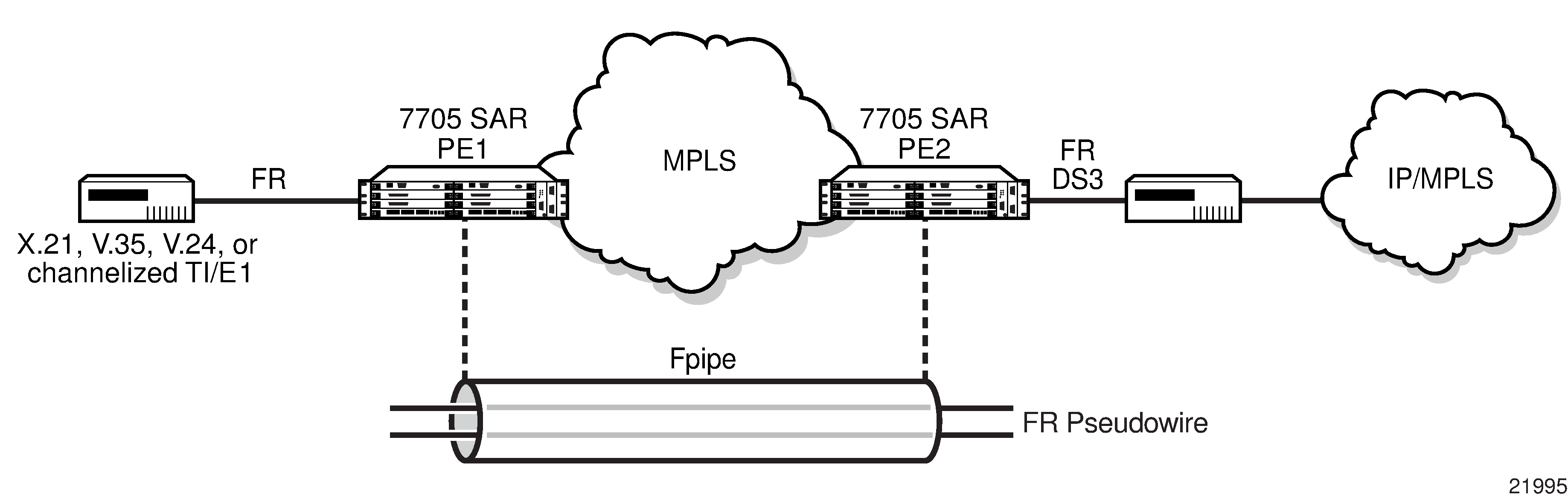
Fpipe SAPs are supported on the following:
16-port T1/E1 ASAP Adapter card
32-port T1/E1 ASAP Adapter card
4-port DS3/E3 Adapter card
12-port Serial Data Interface card
T1/E1 ports on the 7705 SAR-M
Before an Fpipe can be configured on an MDA that supports multiple MDA modes, namely the 16-port T1/E1 ASAP Adapter card, 32-port T1/E1 ASAP Adapter card, and the 4-port DS3/E3 Adapter card, the mda-mode command must be set to cem-fr-hdlc-ppp. Likewise, the AC port that is bound to the Fpipe SAP must have the encap-type command set to frame-relay. See the 7705 SAR Interface Configuration Guide for more information about how to set the mda-mode command at the card level and the encap-type command at the port/channel level. See Service Support for more information about the supported chassis and the port- and channel-level configuration requirements.
Frame Relay SAP-to-SAP Service
FR VLLs can be configured with both endpoints (SAPs) on the same 7705 SAR, which is referred to as an FR SAP-to-SAP or local FR service. FR SAP-to-SAP emulates local FR switching between two FR endpoints on the same 7705 SAR node.
Frame Relay Traffic Management
Traffic management of frame relay VLLs is achieved through the application of ingress and egress QoS policies to SAPs.
Ingress SAP Classification and Marking
If the de-1-out-profile is configured, DE=1 frames are classified as out-of-profile and are not subject to the CIR marking. All received DE=0 frames that exceed the CIR are marked as out-of-profile and have the DE set to 1 regardless of whether the de-1-out-profile command is enabled or disabled. See the 7705 SAR Quality of Service Guide for more information about the de-1-out-profile command.
Frame Relay Encapsulation
FR Frame shows the standard FR frame.
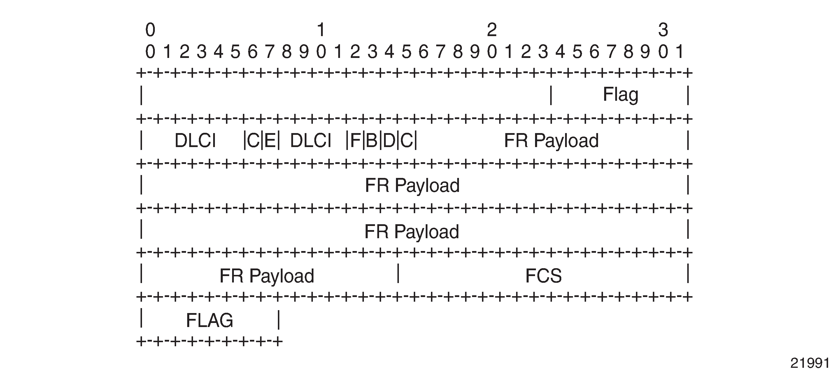
FR PW 1-to-1 MPLS PSN Encapsulation shows the one-to-one mapping mode for FR encapsulation over an MPLS network according to RFC 4619. The FR service payload can be n octets.
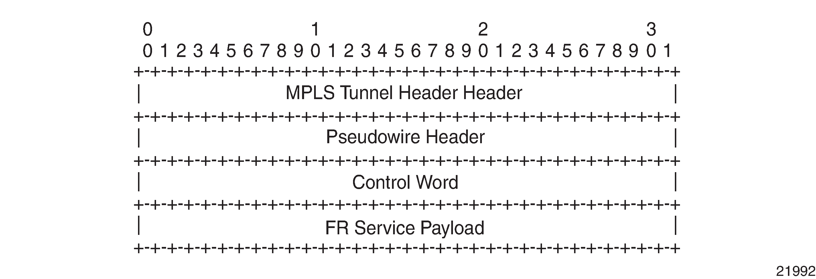
The native FR PDU is processed as follows:
Flag—The FR flags are removed during encapsulation.
FCS—The FCS can use a 2-byte CRC-CCITT or a 4-byte CRC-32. The CRC is configurable. The FCS is removed during encapsulation.
Frame header—A 2-byte DLCI frame header is supported. The header is removed during encapsulation.
The F, B, D, and C control bits are copied into the control word as described in Frame Relay PW Control Word.
Frame Relay PW Control Word
The control word is required for FR one-to-one mode. FR PW Control Word shows the FR PW control word.
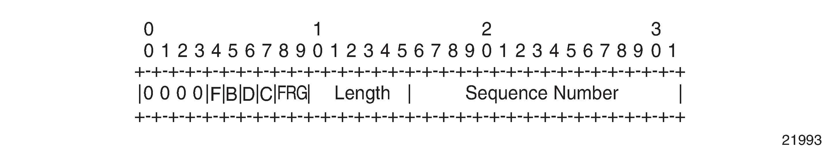
Control Word Bit Descriptions describes the bits used in the FR PW control word.
Bit |
Description |
|---|---|
Bits 0 to 3 |
4 bits. Bits 0 to 3 are always set to 0 to indicate the presence of the PW. |
F |
Bit 4; FR FECN bit. The F bit is copied from the FR frame. |
B |
Bit 5; FR BECN bit. The B bit is copied from the FR frame. |
D |
Bit 6; FR DE bit. The D bit is copied from the FR frame, but can be reset as a result of the ingress frame policy, as described in Frame Relay Traffic Management. |
C |
Bit 7; FR frame C/R bit. The C bit is copied unchanged from the FR frame. |
FRG |
2 bits (bits 8 and 9). FRG bits are not supported. The bits must be set to 0. |
Length |
6 bits (bits 10 to 15). If the frame length (defined as the length of the FR Layer 2 payload plus the length of the control word) is less than 64 octets, the length field must be set to the PW payload length. Otherwise, the length field must be set to zero. The value of the length field, if non-zero, is used to remove the padding characters by the egress PE. See the control-word command description for more information. |
Sequence Number |
A 16-bit, unsigned circular space. Sequence numbers provide a mechanism to ensure the ordered delivery of PW packets. The sequence number field is not supported. The sequence number value 0 indicates that the sequence number check algorithm is not used. |
Status Signaling and OAM Propagation
The 7705 SAR supports the mapping and notification of defect states between an FR PW and an ACs in accordance with Pseudowire (PW) OAM Message Mapping draft-ietf-pwe3-oam-msg-map-14.txt, Section 10. Failures in the network are propagated to the customer edge using LMI messages. LMI and AC failures are propagated to the network using PW status signaling.
HDLC VLL (Hpipe) Services
This section provides information about the Hpipe service. Topics in this section include:
Hpipe configuration information is found under the following topics:
See Service Support for information about the adapter cards and chassis that support HDLC VLL services.
Hpipe Service Overview
An HDLC PW is used to carry HDLC PDUs over an MPLS network. HDLC PWs enable service providers to offer emulated HDLC services over existing MPLS networks.
HDLC mode provides port-to-port transport of HDLC-encapsulated traffic. The HDLC PDU is transported in its entirety, including the HDLC address and control fields, but the HDLC flags and the FCS are excluded. If the optional control word is used, the flag bits in the control word are not used and must be set to 0 for transmitting and must be ignored upon receipt.
HDLC PWs are implemented in accordance with RFC 4618.
Hpipe SAPs are supported on the following:
16-port T1/E1 ASAP Adapter card
32-port T1/E1 ASAP Adapter card
12-port Serial Data Interface card
T1/E1 ports on the 7705 SAR-M
Before HDLC SAPs can be configured on the 16-port T1/E1 ASAP Adapter card or 32-port T1/E1 ASAP Adapter card, the mda-mode command must be set to cem-fr-hdlc-ppp at the card level. See the 7705 SAR Interface Configuration Guide for more information about how to set the mda-mode command. See Service Support for more information about the supported chassis and the port- and channel-level configuration requirements.
Only ports that are configured with HDLC encapsulation can be mapped to an Hpipe SAP. HDLC encapsulating ports do not terminate the HDLC. The ports pass the HDLC frames through the Hpipe. HDLC encapsulated ports can pass through any HDLC-framed traffic, such as Cisco-HDLC, FR, PPP, and so on.
HDLC encapsulation can be used on a port to transmit Cisco-HDLC frames over an H-pipe. To transport Cisco-HDLC traffic over an Hpipe, the attachment circuit (AC) port that is bound to the Hpipe SAP must have the encap-type command set to hdlc, not cisco-hdlc. See the 7705 SAR Interface Configuration Guide for more information about how to set the encap-type command.
HDLC VLL for End-to-End HDLC Service
HDLC VLL for End-to-End HDLC Service shows an example of how a mobile operator can deploy end-to-end HDLC services over an MPLS network.
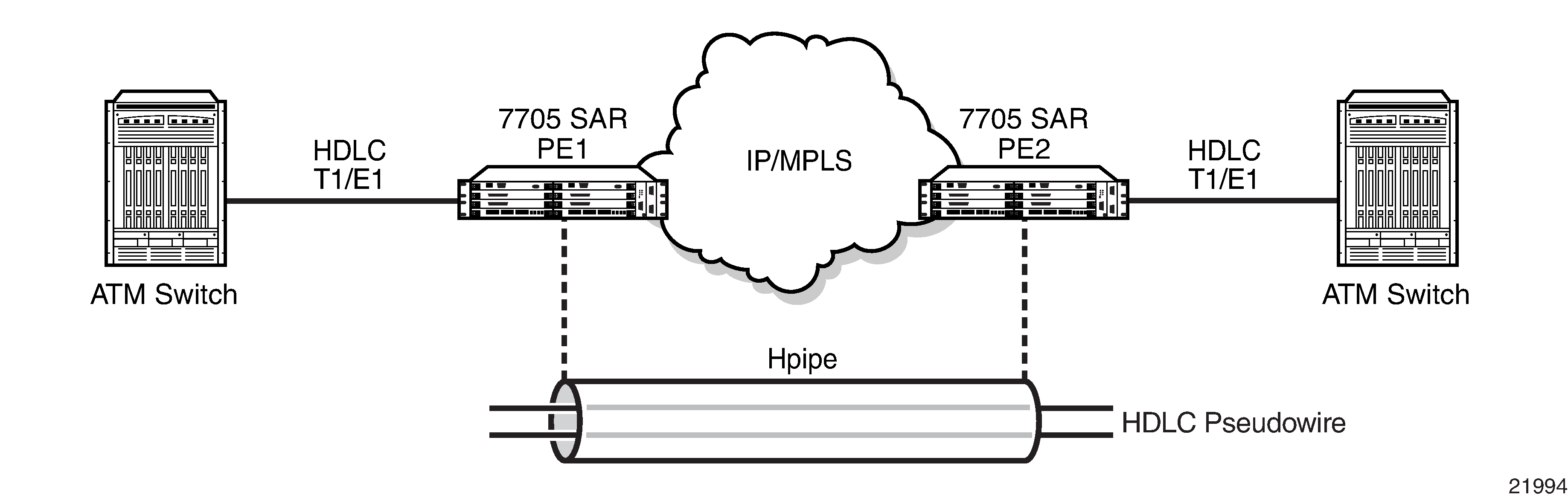
In HDLC VLL for End-to-End HDLC Service, the CE (an ATM switch) transmits HDLC PDUs and receives HDLC PDUs over the physical layer between the CE and a 7705 SAR (PE1). The native service processing (NSP) function in PE1 performs the packet processing, such as bit stuffing, PW-PW bridging, L2 encapsulation, shaping, and policing, for the HDLC packets that are forwarded to the PW termination point in PE1. The PW, which terminates at a logical port in the PE1, delivers the unaltered HDLC packets that are received across the MPLS network to the corresponding logical port on PE2 at the other end of the PW.
The PW termination points on each PE represent the operations that establish and maintain the PW and that encapsulate and decapsulate the HDLC packets. For more information, see the PW reference diagram packet processing that supports the HDLC PW as described in RFC 4618.
HDLC SAP-to-SAP Service
HDLC VLLs can be configured with both endpoints (SAPs) on the same 7705 SAR, which is referred to as an HDLC SAP-to-SAP or local HDLC service. HDLC SAP-to-SAP emulates local HDLC switching between two endpoints on the same 7705 SAR node.
HDLC Encapsulation
HDLC VLL Frame shows a typical HDLC VLL frame.
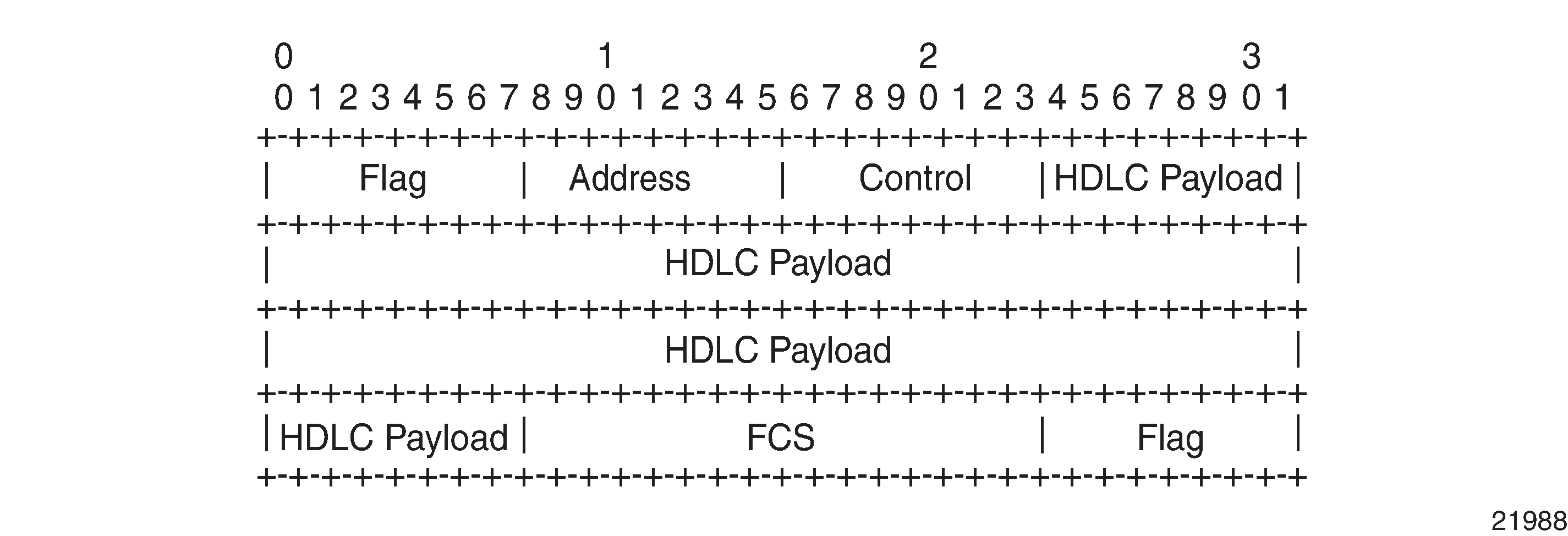
HDLC VLL Frame with MPLS Encapsulation shows a typical HDLC VLL frame together with its MPLS tunnel encapsulation.
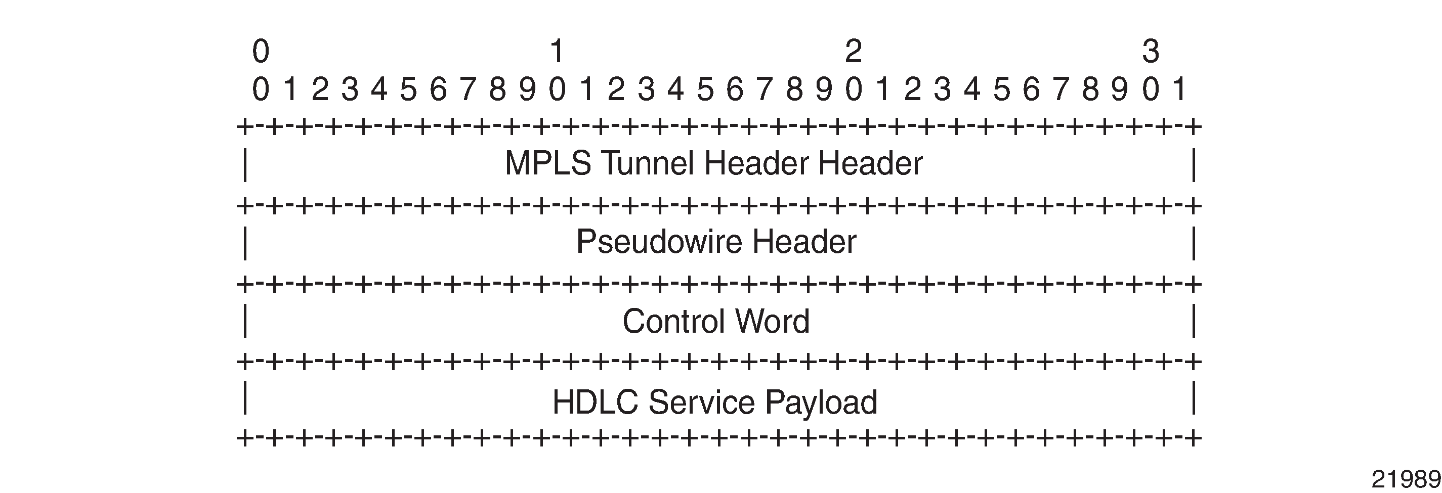
The native HDLC PDU is processed as follows:
Flag—the HDLC flags are removed during encapsulation
FCS—the FCS can use a 2-byte CRC-CCITT or a 4-byte CRC-32. The CRC is configurable. The default value is 2-byte. The FCS is removed during encapsulation.
Address—HDLC address is retained
Control—HDLC control is retained
The MPLS tunnel is used to transport the encapsulated HDLC across the PSN and the PW header is appended to the modified HDLC PDU as described in RFC 4618. The HDLC control word is inserted in the frame before the HDLC payload. See HDLC PW Control Word and Payload Size for information.
HDLC PW Control Word and Payload Size
HDLC VLLs support an optional control word (CW). The control word must be used for any HDLC (Hpipe) pseudowire service that transports packets that are less than 64 bytes.
To switch frames through the 7705 SAR switch fabric, the frame size must be 64 bytes or larger. If the HDLC frames received at the SAP are not 64 bytes or larger, the 7705 SAR pads the HDLC payload at the access ingress to ensure that the HDLC payload can be passed through the switch fabric and transported properly across the network. When padding occurs, the size of the original payload must be indicated in the length field of the control word so that at the termination of the HDLC PW, the far-end device can correctly determine the actual size of the HDLC payload, remove the padding, and forward the original, non-padded HDLC payload to the access egress. See RFC 4618, section 4.1 part-2. HDLC PW Control Word shows the HDLC PW control word.
Control Word Bit Descriptions describes the bits used in the HDLC PW control word.
Bit |
Description |
|---|---|
Bits 0 to 3 |
The use of bits 0 to 3 is described in RFC 4385. The bits are always set to 0 to indicate the presence of the CW. |
Flags |
4 bits (bits 4 to 7). No flags are defined for the HDLC PW. The bits must be set to 0 and must be ignored by the PE. |
FRG |
2 bits (bits 8 and 9). FRG bits are not supported. The bits must be set to 0. |
Length |
6 bits (bits 10 to 15). The length represents the combined size of the CW and the HDLC payload. If the combined size is less than 64 bytes, this field must be populated to indicate the actual size of the HDLC payload that is received at the access ingress. At the access egress, this field is used to strip bytes that are appended for padding purposes. If the combined size of the CW and the HDLC payload exceeds 64 bytes, all bits in this field must be set to 0. See the control-word command description for more information. |
Sequence Number |
The sequence number is used to provide the common PW sequencing function as well as detection of lost packets. The sequence number field is not supported on the 7705 SAR. |
See Pseudowire Control Word for more information.
Status Signaling
The HDLC PW supports status signaling in accordance with RFC 4618, section 5.1. When the PE detects a status change in the attachment circuit (AC) status, such as an AC physical link failure, or if the AC is administratively disabled, the PE sends the appropriate PW status notification message that corresponds to the HDLC AC status. The local PW status is also reflected in a PW status notification message, as described in RFC 4447, section 5.4.
OAM Propagation
The 7705 SAR supports OAM propagation between AC SAPs and the PW and vice versa. For example, if no viable tunnel exists from the AC to the eLER, the status of the local SAP is set to the down state. Likewise, when a local SAP fails, the 7705 SAR sends a PW status message informing the far end of an AC ingress/egress fault. The far-end eLER then sets the status of the service and the SAP to the down state.
IP Interworking VLL (Ipipe) Services
This section provides information about the Ipipe service.
Topics in this section include:
Ipipe configuration information is found under the following topics:
See Service Support for information about the adapter cards and chassis that support IP interworking VLL services.
Ipipe Service Overview
An Ipipe pseudowire (IP PW) enables service interworking between different link layer technologies and network interworking between connections with the same link layer technologies. IP PWs provide an efficient means to connect Layer 3 IP traffic to the IP/MPLS network, even without access to VLANs.
An Ipipe is a point-to-point Layer 2 service where the customer data is encapsulated and transported across an MPLS or IP network. An Ipipe service transparently forwards all packets received on one SAP to the other SAP. No native IP routing of customer packets occurs.
IP interworking allows connections to be created with any combination of PPP, MLPPP, Ethernet, LAG, FR, and Cisco HDLC (cHDLC) SAPs, but the payload must always be IP. Ipipes can be used to transport IP payloads more efficiently than Epipes because an Ipipe service does not need to forward the Ethernet header information.
IP Pseudowires Between SAR Nodes shows an example of IP connectivity between a host attached to a point-to-point access circuit (FR, cHDLC, and PPP) with routed PDU IPv4 encapsulation and a host attached to an Ethernet interface. Both hosts are on the same LAN segment.
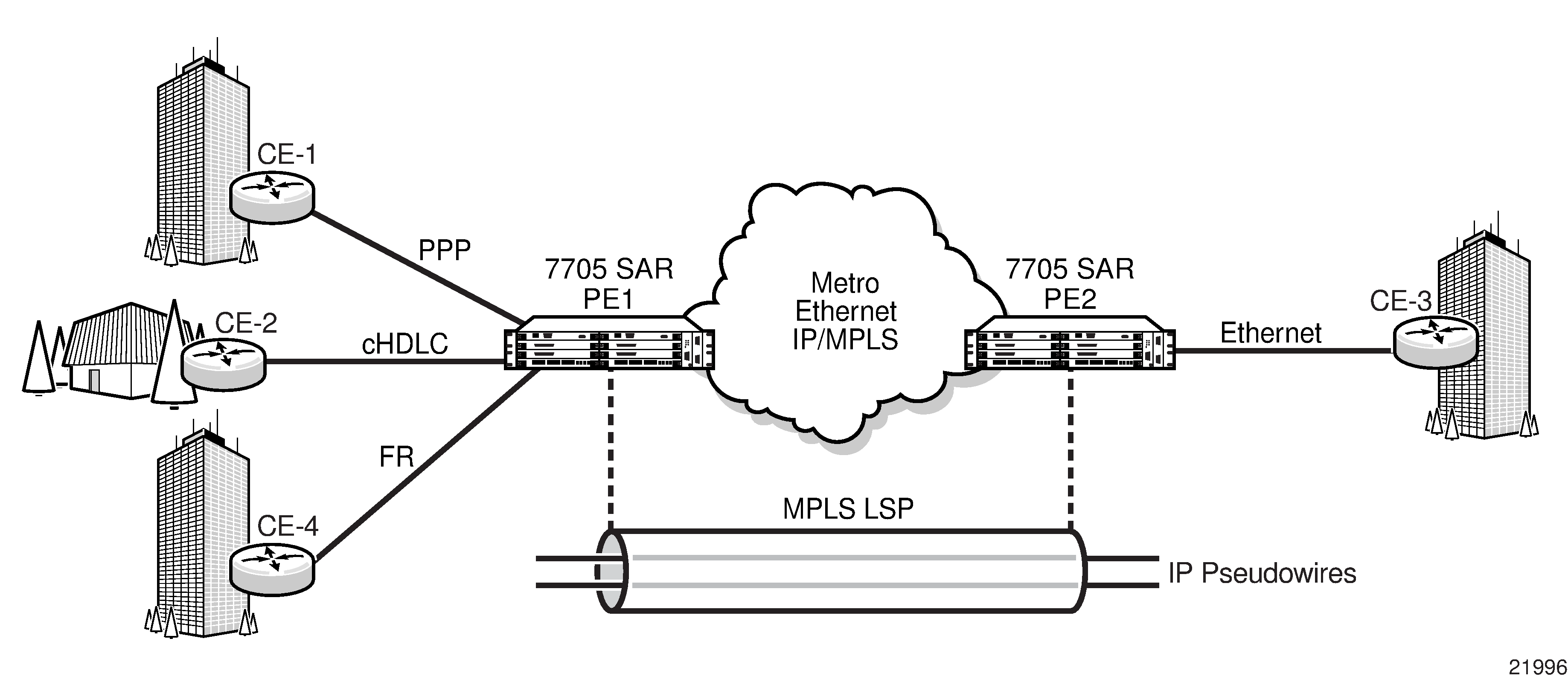
A frame relay SAP makes use of RFC 2427, Multiprotocol Interconnect over Frame Relay, routed PDU encapsulation of an IPv4 packet. A PPP interface makes use of RFC 1332, The PPP Internet Protocol Control Protocol (IPCP), for PPP IPCP encapsulation of an IPv4 packet. A Cisco HDLC SAP uses the routed IPv4 encapsulation. The PW uses the IP Layer 2 transport pseudowire encapsulation type.
IP Interworking VLL Datapath
In order to be able to forward IP packets between CE 1 and CE 3 in IP Pseudowires Between SAR Nodes, PE 2 is configured with both CE 1 and CE 3 IP addresses. These are host addresses and are entered in the /32 format.
PE 2 maintains an ARP cache context for each IP interworking VLL and responds to ARP request messages received on the Ethernet SAP. PE 2 responds with the Ethernet SAP configured MAC address as a proxy for any ARP request for the CE 1 IP address. PE 2 silently discards any ARP request messages received on the Ethernet SAP for addresses other than CE 1. Likewise, PE 2 silently discards any ARP request messages with source IP addresses other than CE 3. In all cases, PE 2 keeps track of the association of IP to MAC addresses for ARP requests it receives over the Ethernet SAP. All entries are subject to aging.
In order to forward unicast frames destined for CE 3, PE 2 needs to know the MAC address of CE 3. If there is no entry in the ARP cache, PE 2 sends an ARP request message for the CE 3 MAC address over the Ethernet SAP.
IP broadcast and IP multicast packets are sent on the Ethernet SAP using the broadcast or direct-mapped multicast MAC address.
In order to forward unicast frames destined for CE 1, PE 2 validates the MAC destination address of the received Ethernet frame. It should match that of the Ethernet SAP. PE 2 then removes the Ethernet header and encapsulates the IP packet directly into a pseudowire with or without the optional control word. PE 1 removes the pseudowire encapsulation and forwards the IP packet over the SAP using PPP encapsulation.
When a packet reaches the access egress and the configured SAP is over a VLAN, the node pushes (inserts) the appropriate VLAN tag into the Ethernet frame header before forwarding the Ethernet frame out of the port. Ethernet frames at the access egress can also be marked with appropriate dot1 priority bits if the dot1 priority QoS profile is assigned to the forwarding class configuration.
Ethernet frames mapped to an Ipipe service can have a maximum of two VLAN tags. Frames with more than two VLAN tags are dropped at the Ipipe access ingress SAP.
At access ingress, PE 1 performs proxy PPP negotiation and provides the IP address of the remote CE 3 device to CE 1 during IPCP negotiation using the IP-Address option.
A PE does not flush the ARP cache unless the SAP goes administratively or operationally down. The PE with the Ethernet SAP sends unsolicited ARP requests to refresh the ARP cache according to the refresh interval. ARP requests are staggered at an increasing rate if no reply is received to the first unsolicited ARP request. The refresh interval is configurable using the mac-refresh CLI command.
CE IP Address Discovery and Distribution
The following subsections describe the customer edge (CE) IP address discovery methods and how the CE IP address is distributed to remote PE nodes. Topics include:
Manual IP Configuration
Manually configured IP addresses are supported for all attachment circuit types. No further mechanisms for detecting the local or remote CE IP address are required. The PE responds to all ARP requests arriving on Ethernet attachment circuits by replying with the local interface MAC address and the remote CE IP address.
CE IP Address Discovery Using ARP
Ethernet attachment circuits can be configured to use ARP messages that are received from the CE device to determine the local CE IP address. The PE waits for an ARP request from the CE in order to learn the IP address that is associated with the MAC address of the CE. When a valid ARP request is received by the PE from the CE, the ARP cache on the PE is populated with the CE IP/MAC entry. The PE accepts any ARP request message that it receives over the Ethernet SAP and updates the ARP cache entries with no further check. The PE does not validate the source IP address of the ARP request message nor does it try to match the IP address in the ARP request with the programmed IP address.
The 7705 SAR always replies to an ARP request message that is received over the Ethernet SAP. The 7705 SAR replies with the SAP MAC address and a source IP address of the IP address being ARPed without any further check of the latter.
If the SAP status changes to operationally down or if an operator manually clears the ARP cache, the system flushes the ARP cache and the CE address discovered on the SAP is cleared. When the SAP comes into service initially or after a failure, an unsolicited ARP request is not sent over the Ethernet SAP. In the case where multiple ARP messages are received from different CE devices, the last received message prevails and the ARP cache is populated with the newly received information.
An SNMP trap is generated whenever an ARP entry or IPv4 CE address entry is discovered or changed for an Ipipe service.
CE IP Address Discovery for Frame Relay
Frame relay access circuits use INVARP to learn a local CE address and to propagate the remote CE address.
CE IP Address Discovery for cHDLC
The cHDLC access circuits do not need to discover the IP address of the local and remote CE for point-to-point interfaces. The IP addresses remain 0.0.0.0.
CE IP Address Discovery for PPP/MLPPP
The address of a locally attached CE device can be learned via IPCP. If the Ipipe uses a spoke SDP, when the 7705 SAR sends the label mapping message, this learned address is not included in the address list TLV in the interface parameters field of the pseudowire FEC TLV.
CE IP Address Distribution to Remote PE Nodes
The PE includes an IP address list TLV in the label mapping message of the PW FEC in order to communicate the local CE IP address to the remote PE. If the IP address is set to 0.0.0.0, it is assumed that the connected CE IP address is unknown. For point-to-point connections such as frame relay and cHDLC, an IP address of 0.0.0.0 does not affect the PW status or stop the flow of IP traffic through the Ipipe. Broadcast interfaces such as Ethernet must learn the local CE IP address and MAC relationship before unicast traffic can be sent, but the remote PE IP address can remain as 0.0.0.0. The value of the remote PE IP address is always 0.0.0.0 when the remote PE access circuit is PPP/MLPPP (IPCP) or cHDLC.
If the CE IP address changes, an LDP notification message is sent to the remote PE with the new IP address of the CE.
IP SAP-to-SAP Service
IP VLLs can be configured with both endpoints (SAPs) on the same 7705 SAR, which is referred to as an IP SAP-to-SAP or local IP service. IP SAP-to-SAP emulates local IP switching between two endpoints on the same 7705 SAR node.
Hardware Support for Interworking IP PWs
The following table lists the hardware that supports interworking IP PWs.
|
MDA Type |
Interworking PWs |
||||||
|---|---|---|---|---|---|---|---|
Eth to IP PW |
PPP to IP PW |
MLPPP to IP PW |
MC-MLPPP to IP PW |
FR to IP PW |
cHDLC to IP PW |
ATM to IP PW |
|
6-port Ethernet 10Gbps Adapter card |
✓ |
||||||
8-port Gigabit Ethernet Adapter card |
✓ |
||||||
10-port 1GigE/1-port 10GigE X-Adapter card |
|||||||
— x1-10gb-sf+ mode |
|||||||
— x10-1gb-sfp mode |
✓ |
||||||
16-port T1/E1 ASAP Adapter card |
|||||||
— Channelized |
✓ |
✓ |
✓ |
||||
— Clear channel |
✓1 |
✓ |
✓ |
✓ |
✓1 |
||
32-port T1/E1 ASAP Adapter card |
|||||||
— Channelized |
✓ |
✓ |
✓ |
||||
— Clear channel |
✓1 |
✓ |
✓ |
✓ |
✓1 |
||
4-port DS3/E3 Adapter card |
|||||||
— on n x DS0 |
|||||||
— on DS1/E1 |
|||||||
— Clear channel (DS3 or E3) |
✓ |
||||||
2-port OC3/STM1 Channelized Adapter card |
|||||||
— on n x DS0 |
✓ |
||||||
— on VT1.5/VC12 |
✓ |
✓ |
|||||
4-port OC3/STM1 / 1-port OC12/STM4 Adapter card |
|||||||
— on VT1.5/VC12 |
✓ |
✓ |
✓ |
||||
12-port Serial Data Interface card |
|||||||
— on RS-232 ports |
|||||||
— on V.35/X.21 ports |
✓ |
✓ |
✓ |
||||
4-port SAR-H Fast Ethernet module |
✓ |
||||||
4-port T1/E1 and RS-232 Combination module |
✓ |
✓ |
✓ |
||||
6-port SAR-M Ethernet module |
✓ |
||||||
7705 SAR-A |
✓ |
✓ |
✓ |
✓ |
|||
7705 SAR-Ax |
✓ |
||||||
7705 SAR-H |
✓ |
||||||
7705 SAR-M |
✓ |
✓1 |
✓ |
✓ |
✓ |
✓1 |
|
7705 SAR-Wx |
✓ |
||||||
7705 SAR-X |
✓ |
✓1 |
✓ |
✓ |
✓1 |
||
Note:
Supported on framed DS1/E1 and unframed E1
Control Word
IP interworking VLLs support an optional control word. The control word may be required to interoperate with devices at the far end. If the control word is enabled, it is set to all zeros and ignored on egress.
See Pseudowire Control Word for more information.
Termination at Access
The following sections describe the termination requirements and features for interworking pseudowires. Topics include:
PPP and MLPPP Termination
For PPP termination, ports must be configured in access mode with IPCP encapsulation. Access ports on the 12-port Serial Data Interface card or 2-port OC3/STM1 Channelized Adapter card must be configured with IPCP encapsulation to support PPP/MLPPP termination for an interworking pseudowire. The ppp-auto encapsulation type applies only to network-side terminations.
FR Termination
The following features are supported for FR termination:
ports must be configured for access mode according to Q.922 Annex A frame format
RFC 2427, Multiprotocol Interconnect over Frame Relay, routed PDU encapsulation of an IPv4 packet
UNI DCE and DTE
NLPID (0xCC) IPv4 encapsulation
LMI (see FR LMI)
configurable service MTU of 1 to 2048 bytes. When encapsulated in the IPv4 PDU, the FR flags, FCS, and FR header are removed. The resulting data is the Ipipe payload represented in the IP Datagram field in FR Header with NLPID Support for IP Interworking PW.
Figure 24. FR Header with NLPID Support for IP Interworking PW 
cHDLC Termination
The following features are supported for cHDLC termination:
ports must be configured for access mode according to the cHDLC frame format. See the 7705 SAR Interface Configuration Guide for information about how to configure the encap-type command to cisco-hdlc.
IP encapsulation (0x0800). cHDLC Header Frame shows the cHDLC header frame.
keepalive support using SLARP (0x8035). SLARP Keepalive Frame shows the SLARP keepalive frame.
configurable service MTU of 1 to 2048 bytes. When encapsulated in the IPv4 PDU, the cHDLC packet shown in cHDLC Header Frame is modified to remove the flag, address, control, protocol ID, and FCS.
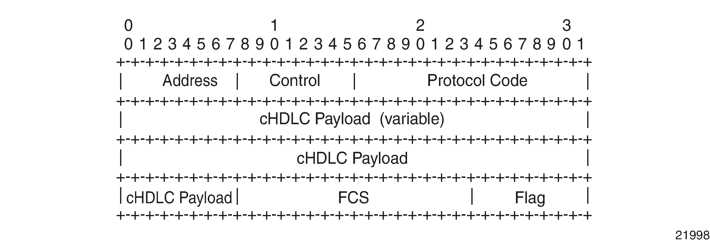
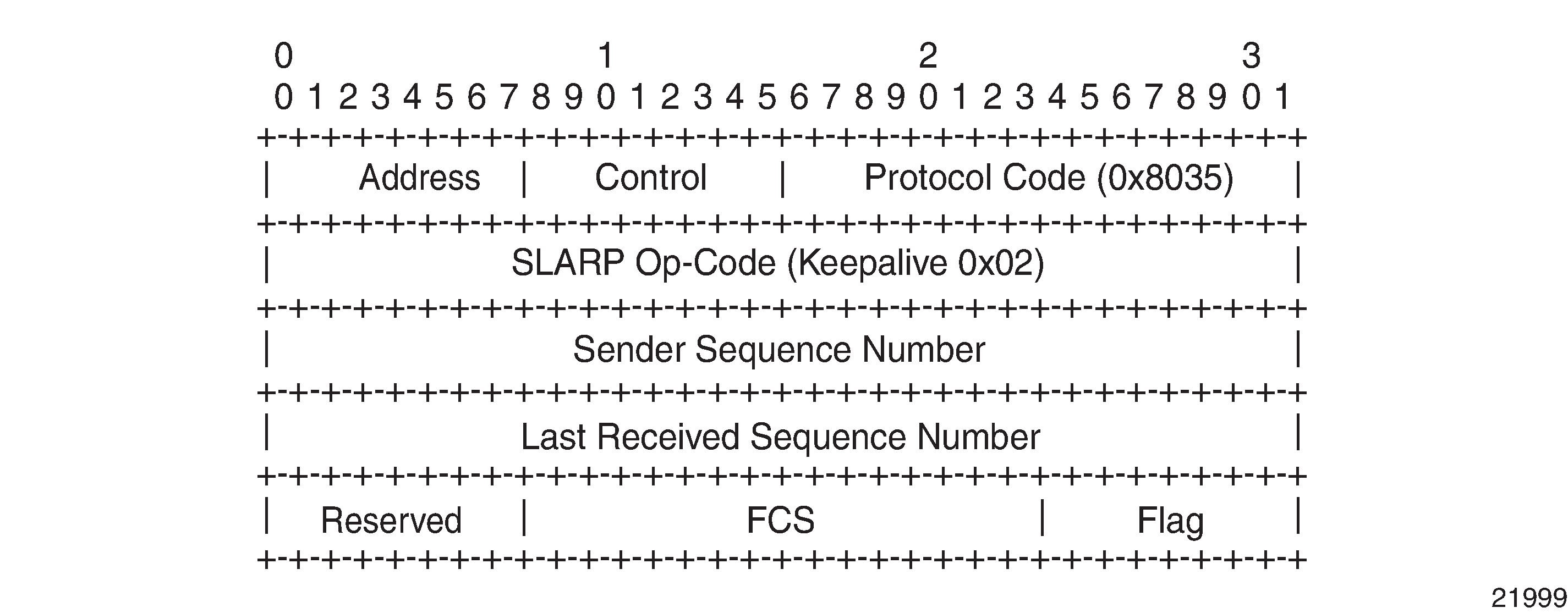
See the 7705 SAR Interface Configuration Guide for more information about how to configure access ports for interworking IP PWs.
PPP and MLPPP Termination on 2-port OC3/STM1 Channelized Adapter Cards
PPP termination is supported on DS1/E1 and n x DS0 (64 kb/s) channels.
MLPPP termination is supported on DS1/E1 channels.
One use for PPP and MLPPP termination to IP pseudowires is in fixed backhaul networks with customers connected to the network via DS1/E1 or n x DS1/E1 rates.
PPP and MLPPP to IP PWs on 2-port OC3/STM1 Channelized Adapter Cards shows an example of a network using PPP and MLPPP encapsulation to IP PWs on a 2-port OC3/STM1 Channelized Adapter card.
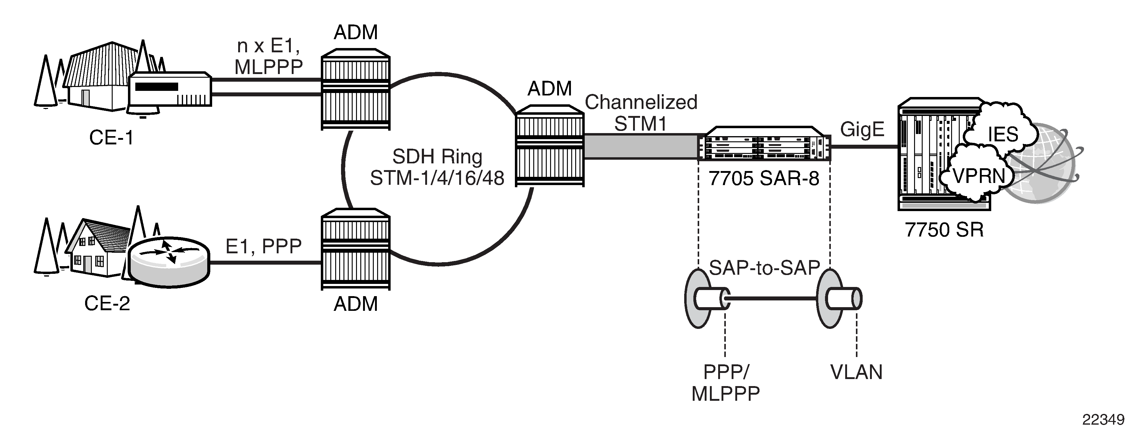
Customer traffic aggregation remains on the available SONET/SDH infrastructure and is sent to a 2-port OC3/STM1 Channelized Adapter card on the 7705 SAR, where the PPP/MLPPP encapsulation termination takes place. Using an IP PW with PPP/MLPPP encapsulation from a SAP-to-VLAN SAP, the 7705 SAR passes the data to a 7750 SR. The 7750 SR offers the necessary scale of IP services, such as IES or VPRN, needed to handle the large amount of traffic coming from each OC3/STM1 port.
After terminating PPP/MLPPP encapsulated traffic on a channelized OC3/STM1 port, the 7705 SAR switches the IP traffic, without performing any IP lookup, to another SAP over an Ipipe. IP traffic is then passed on to the 7750 SR with a unique VLAN identifier on a per-connection basis.
See the 7705 SAR Interface Configuration Guide for more information about how to configure 2-port OC3/STM1 Channelized Adapter card ports for interworking IP PWs and PPP/MLPPP termination.
Traffic Management
Traffic Management for FR IW SAPs
Traffic management of interworking SAPs is achieved by applying ingress and egress QOS policies to SAPs. Access ingress forwarding classes are determined by inspecting the DSCP marking of the IP packets to determine the queuing and the EXP bit setting of packets. If all traffic for a DLCI must be classified as a single forwarding class, you can define a policy to classify all DSCP values from the IP header to one forwarding class.
Status Signaling
FR LMI
LMI enables the exchange of information between the CE and the LER about the status of the link, device, and logical circuit. The frame relay CE device (the DTE) begins an LMI exchange by sending a Status Enquiry message. DTE status enquiry message supports link integrity verification requests. The frame relay network (the DCE) completes the exchange by responding with a Status message.
The DCE status messages support the following response types:
full status
link integrity verification
single PVC status
The LMI protocol operates over a dedicated PVC of a frame relay link. Since LMI occupies its own PVC, its link signaling cannot congest or interfere with traffic on the PVCs that carry subscriber data.
The following standards are supported:
ANSI T.617 Annex D
ITU-T Q.922 Annex A
Cisco Rev.1
IP Filters (Ipipe)
IP filters are applied to Ipipe SAPs in the ingress direction, as described below. For a full list of entities to which IP filters can be applied, see IP Filter Policies.
IP pseudowires are generally used to transparently switch traffic across an MPLS network to the far end. However, in some cases, the traffic that is switched over the network, consuming valuable bandwidth, is just discarded at the other end of the pseudowire. As well, with the 7705 SAR expanding into areas such as vertical markets, and with local area networks being connected to the 7705 SAR Ethernet ports, an increasing amount of traffic must stay local and not pass through the MPLS network to the far end. By using IP filters at the access ingress, operators can determine what traffic is passed through the pseudowire and therefore use the network links more efficiently.
Another use for IP filters is in cases where a customer router is connected to an access port on the 7705 SAR with PPP/MLPPP encapsulation. The service provider may want to filter incoming traffic from the customer at the boundaries of the network.
IP filters can also be used for security purposes, by allowing access only to designated services (for example, allowing email and FTP services while disallowing Telnet services) at the origin of the traffic.
IP filter policies specify either a forward or a drop action for packets, based on information specified in the match criteria. Within each filter policy, you can create entries that define matching criteria.
The same IP filter policy can be assigned to any entity (network interfaces, IP pseudowires, Ethernet pseudowires, IES, and VPRN services), all of which can be configured on the same adapter card. For example, a filter policy defined as ‟filter-5” can be assigned to multiple Ipipe SAPs and, simultaneously, to network interfaces on the same adapter card.
A filter policy assigned to an entity on one adapter card can also be assigned to any entity on another adapter card. For example, a filter policy defined as ‟filter-2” can be assigned to an Ipipe on an Ethernet Adapter card and to a network interface on another Ethernet Adapter card.
Assigning the same filter policy to different entities on a card counts as using one filter policy.
Configuration and assignment of filter policies is similar for network interfaces, IES management SAPs, Ethernet and IP pseudowire SAPs, VPRN and IES SAPs and spoke SDPs, and VPLS SAPs and SDPs (spoke and mesh). This guide describes the assignment of filter policies to SAPs and SDPs. See the 7705 SAR Router Configuration Guide, ‟Filter Policies”, for information about configuring filter policies and assigning them to network interfaces.
Pseudowire Switching
Topics in this section include:
Overview
The pseudowire switching feature provides the user with the ability to create a VLL service by cross-connecting two spoke SDPs.
Services with one SAP and one spoke SDP are created normally on the PE; however, when a pseudowire originates at customer equipment and not the 7705 SAR, the target destination of the SDP is the 7705 SAR pseudowire switching node instead of the remote PE. In such cases, the user must configure a VLL service on the pseudowire switching node (the 7705 SAR, in this case) using the two SDPs and no SAP. This creates a VLL service that travels over two different types of tunnels. The first pseudowire segment connects the Node B to the 7705 SAR, and the second segment connects the 7705 SAR to a 7750 SR node. Simplex to Simplex Pseudowire Switching shows an example of a VLL pseudowire switching service.
For the 7750 SR node, there is no implementation change required. The pseudowire segment is treated as a 7705 SAR-initiated dynamic ATM pseudowire. The 7705 SAR signals for the ATM pseudowire and negotiates all required parameters, including the pseudowire label, control word, and VCCV type.
The pseudowire switching node acts in a passive role with respect to signaling of the pseudowires. The node waits until one or both of the PEs send the label mapping message before relaying it to the other PE. This is because it needs to pass the interface parameters of each PE to the other. For example, the 7705 SAR assumes the pseudowire payload from the Node B, then signals for the ATM pseudowire to the far end and negotiates all required parameters, including the pseudowire label, control word, and VCCV type.
The switching pseudowire inserts a pseudowire switching point TLV indicating the system address in the label mapping message. This TLV is useful because it allows for troubleshooting of the path of the pseudowire, especially if multiple pseudowire switching points exist between the two PEs. The TLV also helps in loop detection of T-LDP signaling messages, where a switching point receives a label mapping message that it already relayed. The switching point TLV is inserted in pseudowire status notification messages when they are sent end-to-end or from a pseudowire switching node toward a destination PE. See Pseudowire Switching TLV for more information.
Pseudowire OAM is supported for dynamic switching pseudowires and allows the 7705 SAR pseudowire switching node to relay end-to-end pseudowire status notification messages between the two PEs. The 7705 SAR can generate a pseudowire status and send it to one, or both, of the PEs by including its system address in the pseudowire switching point TLV. This allows a 7705 SAR PE to identify the origin of the pseudowire status notification message.
The pseudowire segment between the 7705 SAR and the 7750 SR supports OAM tools as well as BFD; however, since Node Bs are not dual-homed, OAM tools operating on this pseudowire segment can only provide informative messages. The 7705 SAR responds to Node B-initiated ping packets if the destination IP address is the system IP or interface IP address of the 7705 SAR. If the IP packet does not contain a SAR destination IP address, the 7705 SAR does not respond, and instead, forwards the packet.
Simplex to Simplex Pseudowire Switching shows an example of static-simplex to dynamic-simplex pseudowire switching. This service consists of a SAP and a spoke SDP. However, the target destination of the SDP is not the remote PE but the pseudowire switching node. In addition, the user configures a VLL service on the pseudowire switching node using the two SDPs.
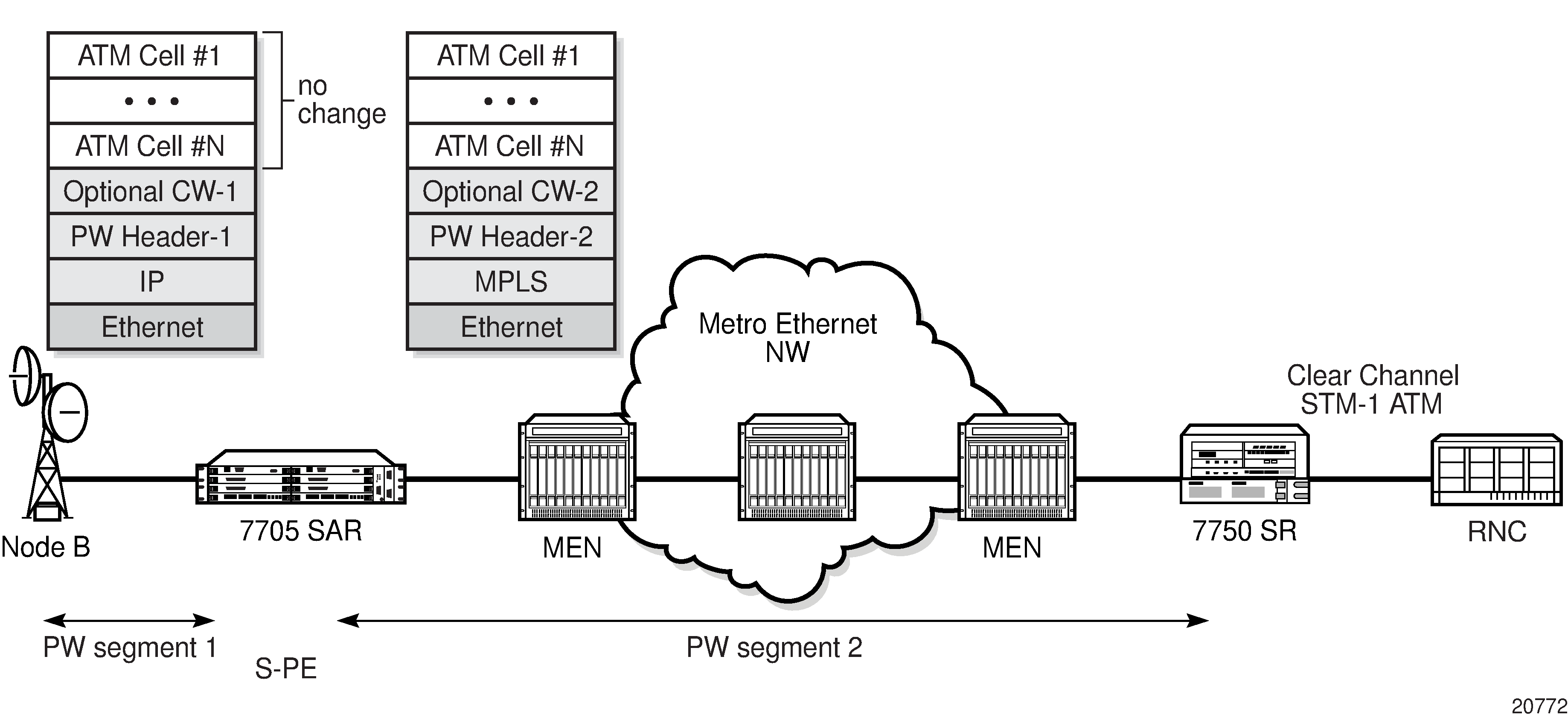
Configuration examples can be found in Configuring PW Switching.
The following table shows the pseudowire switching options supported on the 7705 SAR.
PW Segment 1 |
PW Segment 2 |
|||||||||
|---|---|---|---|---|---|---|---|---|---|---|
Tunnel |
PW |
Tunnel |
PW |
E-pipe |
F-pipe |
H-pipe |
I-pipe |
A-pipe |
Cpipe-ces |
Cpipe-satop |
RSVP-TE, LDP, Static MPLS, IP, or GRE/IP |
Static |
RSVP-TE, LDP, Static MPLS, IP, or GRE/IP |
T-LDP (with or without pseudowire redundancy) |
✓ |
✓ |
✓ |
✓ |
✓ |
✓ |
✓ |
RSVP-TE, LDP, Static MPLS, IP, or GRE/IP |
T-LDP |
RSVP-TE, LDP, Static MPLS, IP, or GRE/IP |
T-LDP |
✓ |
✓ |
✓ |
✓ |
✓ |
✓ |
✓ |
IP |
Static 1 |
MPLS-Static |
Static 1 |
✓ |
✓ |
✓ |
✓ |
✓ |
✓ |
✓ |
Note:
A static-to-static pseudowire switching service will fail if there is more than one S-PE node between the T-PE nodes.
The 7705 SAR supports use of an optional control word on both pseudowire segments. Use of a control word is negotiated by the 7705 SAR and 7750 SR during the signaling phase. The 7705 SAR and 7750 SR negotiate during the signaling phase even if a control word is not used. If a control word is used, the 7705 SAR generates it and configures it with all 0s.
When the 7705 SAR appends or strips the control word to support VCCV ping type 1, the TTL value of the switched pseudowire is reset to 255. If the control word is present on the ingress pseudowire packet and it is not removed because it is on an end-to-end service, the 7705 SAR reduces the pseudowire TTL by 1 at the time of pseudowire switching.
Pseudowire Switching with Pseudowire Redundancy
Pseudowire switching with pseudowire redundancy supports one redundant pseudowire with up to four redundant spoke SDPs. Simplex to Redundant Pseudowire Switching shows an example of a network with simplex to redundant pseudowire switching.
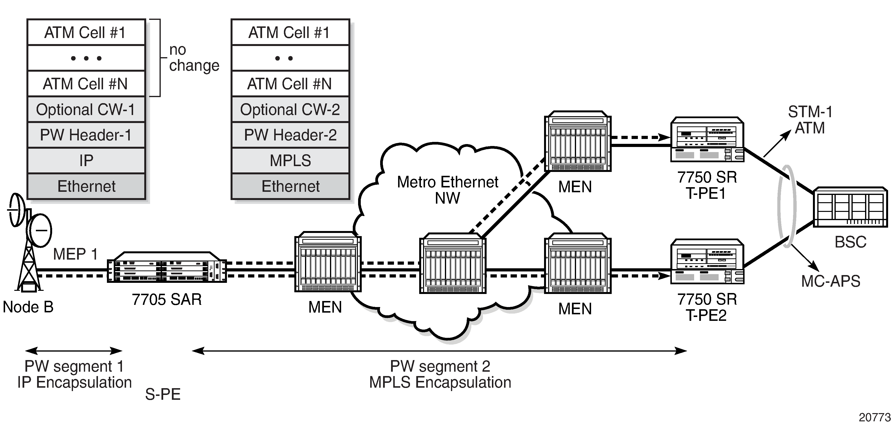
To enable pseudowire redundancy, the first pseudowire segment must be a static pseudowire (that is, T-LDP disabled). The second pseudowire segment can then be configured with up to four redundant spoke SDPs. See Pseudowire Redundancy for instructions on configuring redundancy. Pseudowire switching with pseudowire redundancy also supports standby signaling. See Active/Standby Mode for Pseudowire Redundancy (Standby Signaling) for more information.
Pseudowire Switching Behavior
In the network in Pseudowire Switching Network, T-PE nodes act as leading nodes and pseudowire switching nodes (S-PE nodes) act as followers for the purpose of pseudowire signaling. Switching nodes need to pass the SAP interface parameters of each PE to the other PE. T-PE1 sends a label mapping message for the Layer 2 FEC to the peer pseudowire switching node; for example, S-PE1. It includes the SAP interface parameters, such as MTU, in the label mapping message. S-PE1 checks the FEC against the local information, and if a match exists, it appends the optional pseudowire switching point TLV to the FEC TLV in which it records its system address. T-PE1 then relays the label mapping message to S-PE2. S-PE2 performs a similar operation and forwards a label mapping message to T-PE2.
The same procedures are followed for the label mapping message in the reverse direction; for example, from T-PE2 to T-PE1. S-PE1 and S-PE2 will affect the spoke SDP cross-connect only when both directions of the pseudowire have been signaled and matched.
Pseudowire status notification messages can be generated by the T-PE nodes and/or the S-PE nodes. Pseudowire status notification messages received by a switching node are processed and then passed on to the next hop. An S-PE node appends the optional pseudowire switching TLV, with its system address added to it, to the FEC in the pseudowire status notification message only if it originated the message or the message was received with the TLV in it. If the S-PE node is not the originator or if there is no TLV with the system address in the message, this means that the message was originated by a T-PE node. In this case, the S-PE processes and passes the message without changes except for the VC ID value in the FEC TLV.
The merging of the received T-LDP status notification message and the local status for the spoke SDPs from the service manager at a 7705 SAR PE complies with the following rules.
When the local status for both spokes is up, the S-PE passes any received SAP or SDP-binding generated status notification message unchanged. For example, the status notification TLV is unchanged but the VC-ID in the FEC TLV is set to the value of the pseudowire segment to the next hop.
When the local operational status for any of the spokes is down, the S-PE always sends SDP-binding down status bits regardless if the received status bits from the remote node indicated SAP up or down or SDP-binding up or down.
When one segment of the pseudowire cross-connect at the S-PE is static while the other is signaled using T-LDP, the S-PE operates much like a T-PE from a signaling perspective and as an S-PE from a data plane perspective. The S-PE signals a label mapping message as soon as the local configuration is complete. The control word C-bit field in the pseudowire FEC is set to the value configured on the static spoke SDP.
When the label mapping for the egress direction is also received from the T-LDP peer, and the information in the FEC matches that of the local configuration, the static-to-dynamic cross-connect is established.
In a static-to-dynamic pseudowire switching service, it is possible for the end nodes of the static pseudowire segment to be misconfigured. In this case, an S-PE or T-PE node may receive packets with the wrong encapsulation. If this happens, an invalid payload might be forwarded over the pseudowire or the SAP respectively.
Furthermore, if the S-PE or T-PE node is expecting the control word in the packet encapsulation, and the received packet arrives with no control word but the first nibble below the label stack is 0x0001, the packet may be mistaken for a VCCV OAM packet and may be forwarded to the CSM. In that case, the CSM will perform a check of the IP header fields. If any of the fields fail the check, the VCCV packet will be discarded.
Pseudowire Switching With IP Tunnels
You cannot enable T-LDP dynamic pseudowire establishment on pseudowire switching segments using IP tunnels if the second pseudowire segment is configured for pseudowire redundancy. The pseudowire label, control word, VCCV type, and so on, must be configured manually.
On the first pseudowire segment, ATM pseudowires are natively transported over IP using GRE encapsulation with the IP type set to 0x8847, or IP encapsulation. The destination IP address of pseudowire packets received from the Node B must be set to the system IP or interface IP address of the 7705 SAR. Similarly, the destination IP address of pseudowire packets received from the 7750 SR must be set to the system IP or interface IP address of the Node B. Node B management traffic is transported over the same Ethernet link between the 7705 SAR and the Node B. The 7705 SAR forwards the management IP traffic to its destination based on longest prefix match.
On the second pseudowire segment, ATM pseudowires are transported over MPLS tunnels. The MPLS tunnels can also be used to transport additional cell site traffic, such as BTS traffic using TDM pseudowires, or LTE base station traffic using IP or Ethernet pseudowires.
Pseudowire Switching TLV
Pseudowire Switching TLV shows the format of the pseudowire switching TLV and Pseudowire Switching TLV Field Descriptions describes the fields.
Field |
Description |
|---|---|
pw sw TLV Length |
Specifies the total length of all the following pseudowire switching point TLV fields in octets |
Type |
Encodes how the Value field is to be interpreted |
Length |
Specifies the length of the Value field in octets |
Value |
Octet string of Length octets that encodes information to be interpreted as specified by the Type field |
The following list describes details specific to pseudowire switching point sub-TLVs:
pseudowire ID of last pseudowire segment traversed
pseudowire switching point description string—an optional description string of text up to 80 characters long
IP address of pseudowire switching point—an optional sub-TLV containing the IPv4 address of the pseudowire switching point
MH VCCV capability indication
VLL Service Considerations
This section describes the general 7705 SAR service features and any special capabilities or considerations as they relate to VLL services.
Topics in this section include:
Service Support
The section describes hardware support for the following VLL services:
ATM
Ethernet
Frame relay
TDM
HDLC
IP interworking
ATM
ATM VLL service is supported on the following:
T1/E1 ports on the 2-port OC3/STM1 Channelized Adapter card (when the port is configured for ATM or IMA)
T1/E1 ports on the 4-port DS3/E3 Adapter card (when the port is configured for ATM or IMA)
4-port OC3/STM1 Clear Channel Adapter card (when the port is configured for ATM)
16-port T1/E1 ASAP Adapter card (when the port is configured for ATM or IMA)
32-port T1/E1 ASAP Adapter card (when the port is configured for ATM or IMA)
T1/E1 ports on the 7705 SAR-M
Ethernet
Ethernet VLL service is supported on the following:
6-port Ethernet 10Gbps Adapter card
8-port Gigabit Ethernet Adapter card
10-port 1GigE/1-port 10GigE X-Adapter card
Ethernet ports on the 7705 SAR-A
Ethernet ports on the 7705 SAR-Ax
Ethernet ports on the 7705 SAR-H
Ethernet ports on the 7705 SAR-Hc
Ethernet ports on the 7705 SAR-M
Ethernet ports on the 7705 SAR-Wx
Ethernet ports on the 7705 SAR-X
4-port SAR-H Fast Ethernet module
6-port SAR-M Ethernet module
Frame Relay
Frame relay VLL service is supported on the following:
DS3/E3 clear channel or channelized DS1/E1 ports on the 4-port DS3/E3 Adapter card
V.35 and X.21 serial ports on the 12-port Serial Data Interface card
16-port T1/E1 ASAP Adapter card
32-port T1/E1 ASAP Adapter card
T1/E1 ports on the 7705 SAR-M
TDM
TDM VLL service is supported on the following:
T1/E1 ports and DS3 channels on the 2-port OC3/STM1 Channelized Adapter card
T1/E1 ports (DS3 ports only) and DS3/E3 ports on the 4-port DS3/E3 Adapter card
T1/E1 ports on the 4-port OC3/STM1 / 1-port OC12/STM4 Adapter card
6-port E&M Adapter card (when the port is configured for cem encapsulation)
8-port Voice & Teleprotection card
8-port C37.94 Teleprotection card
12-port Serial Data Interface card
16-port T1/E1 ASAP Adapter card
32-port T1/E1 ASAP Adapter card
4-port T1/E1 and RS-232 Combination module
T1/E1 ports on the 7705 SAR-A
RS-232 serial ports on the 7705 SAR-Hc
T1/E1 ports on the 7705 SAR-M
T1/E1 ports on the 7705 SAR-X
HDLC
HDLC VLL service is supported on the following:
V.35 and X.21 serial ports (super-rate speeds only) on the 12-port Serial Data Interface card
16-port T1/E1 ASAP Adapter card
32-port T1/E1 ASAP Adapter card
T1/E1 ports on the 7705 SAR-M
IP Interworking
IP interworking VLL service is supported on the following:
2-port OC3/STM1 Channelized Adapter card (when the payload is configured as vt1.5/vc12)
DS3/E3 clear channel ports on the 4-port DS3/E3 Adapter card (when the port is configured for frame-relay encapsulation)
6-port Ethernet 10Gbps Adapter card
8-port Gigabit Ethernet Adapter card
10-port 1GigE/1-port 10GigE X-Adapter card
V.35 and X.21 serial ports (super-rate speeds only) on the 12-port Serial Data Interface card (when the port is configured for ipcp, frame-relay, or cisco-hdlc encapsulation)
16-port T1/E1 ASAP Adapter card (on PPP/MLPPP connections)
The 7705 SAR supports PPP to IP PW interworking and cHDLC to IP PW interworking on framed DS1/E1 and unframed E1.
32-port T1/E1 ASAP Adapter card (on PPP/MLPPP connections)
The 7705 SAR supports PPP to IP PW interworking and cHDLC to IP PW interworking on unframed E1.
4-port OC3/STM1 / 1-port OC12/STM4 Adapter card (on PPP/MLPPP connections over DS1/E1 channels)
all ports on the 7705 SAR-A (on PPP/MLPPP connections on the T1/E1 ports)
7705 SAR-H
Ethernet ports on the 7705 SAR-Ax
Ethernet ports on the 7705 SAR-Hc
all ports on the 7705 SAR-M (on PPP/MLPPP connections on the T1/E1 ports; variants with T1/E1 ports also support frame relay and HDLC SAPs on the T1/E1 ports)
Ethernet ports on the 7705 SAR-Wx
-
T1/E1 ports on the 7705 SAR-X
The 7705 SAR-X supports PPP to IP PW interworking and cHDLC to IP PW interworking on framed DS1/E1 and unframed E1.
4-port SAR-H Fast Ethernet module
6-port SAR-M Ethernet module
The 7705 SAR supports PPP to IP PW interworking and cHDLC to IP PW interworking on unframed E1.
SDPs
The most basic SDPs must have the following characteristics:
a locally unique SDP identification (ID) number and a VC-ID
the system IP address of the far-end 7705 SAR routers
an SDP encapsulation type—GRE, IP, or MPLS
SDP Statistics for VLL Services
The 7705 SAR supports local CLI-based and SNMP-based statistics collection for each VC used in the SDPs. This allows for traffic management of tunnel usage by the different services and, with aggregation, the total tunnel usage.
SAP Encapsulations and Pseudowire Types
The section describes encapsulations and PW types for the following VLL services:
Apipe
Cpipe
Epipe
Fpipe
Hpipe
Ipipe
Apipe
ATM VLLs can be configured with both endpoints (SAPs) on the same router or with the two endpoints on different routers. In the latter case, Pseudowire Emulation Edge-to-Edge (PWE3) signaling can be used to establish a pseudowire between the devices, allowing ATM traffic to be tunneled through an MPLS or IP network.
As an alternative to signaled pseudowires, manual configuration of pseudowires is also supported.
The Apipe service supports virtual trunking, VP connections, and VC connections, which are identified by specifying the vc-type when provisioning the Apipe. When vc-type is atm-cell, ATM transparent cell transport mode is used for VT connections. The N-to-1 cell transport mode is supported for VC and VP services (see ATM PWE3 N-to-1 Cell Mode Encapsulation). For VCCs, the value of N can be 1 (N = 1) or greater than 1 (N > 1). The value of N is always 1 for VPCs.
The supported PW service types are 0x0009 (for ATM N-to-1 VCC cell mode, where N is ≥ 1), 0x000A (for ATM N-to-1 VPC cell mode, where N = 1) and 0x0003 (for ATM transparent cell transport mode). See RFC 4717 and RFC 4446 for more information.
Cpipe
Cpipe service supports CESoPSN and SAToP encapsulation over MPLS or GRE tunnels to connect to the far-end circuit. Cpipes support SAP-to-SAP and SAP-to-spoke SDP binding with a default service MTU of 1514 bytes.
The supported PW service types are 0x0011 (SAToP E1), 0x0012 (SAToP T1), 0x0013 (SAToP E3), 0x0014 (SAToP T3), 0x0015 (CESoPSN basic mode), and 0x0017 (CESoPSN TDM with CAS).
Epipe
Epipe service is designed to carry Ethernet frame payloads, so it can provide connectivity between any two SAPs on different nodes that pass Ethernet frames. The following SAP encapsulations are supported on the 7705 SAR Epipe service:
Ethernet null
Ethernet dot1q
Ethernet qinq
While different encapsulation types can be used at either end, encapsulation mismatching can occur if the encapsulation behavior is not understood by connecting devices and if those devices are unable to send and receive the expected traffic. For example, if the encapsulation type on one side of the Epipe is dot1q and the other is null, tagged traffic received on the null SAP will be double-tagged when it is transmitted out of the dot1q SAP.
The supported PW service types are 0x0004 (Ethernet tagged mode), and 0x0005 (Ethernet raw).
Fpipe
Fpipe service supports frame relay services over an MPLS PSN. MPLS label switched paths—also referred to as MPLS tunnels—are used to forward PW packets between two PEs.
The 7705 SAR supports one-to-one mapping of FR VCs to PWs. An MPLS tunnel can contain several PWs, but each PW encapsulates the traffic of one FR VC.
Fpipes support SAP-to-SAP and SAP-to-spoke SDP binding.
Fpipe service supports the 0x0019 (frame relay DLCI) PW service type.
Hpipe
The 7705 SAR supports many-to-one mapping of HDLC PDUs to PWs, which is also known as port mode encapsulation. The Hpipe provides port-to-port transport of HDLC-encapsulated traffic. The HDLC PDU is transported from PE port to PE port in its entirety, including the HDLC address and control fields, but excluding HDLC flags and the FCS.
Hpipes support SAP-to-SAP and SAP-to-spoke SDP binding.
Hpipe service supports the 0x0006 (HDLC) PW service type.
Ipipe
Ipipe service supports Ethernet null, Ethernet dot1q, Ethernet qinq, IPCP, PPP/MLPPP, FR, and cHDLC SAP encapsulation over IP or MPLS. Ipipes support SAP-to-SAP and SAP-to-spoke SDP binding with a default service MTU of 1500 bytes.
Ipipe service supports 0x000B (IP Layer 2 Transport) PW service type.
ATM PWE3 N-to-1 Cell Mode Encapsulation
The 7705 SAR supports N-to-1 cell mode encapsulation for ATM VPCs and VCCs (per RFC 4717), where N represents the number of VCs or VPs that can be multiplexed onto a single ATM VLL.
For VCCs, N is a configurable value where N can be greater than or equal to 1 (N ≥ 1). VCC cell mode supports the 0x0009 (ATM N-to-1 VCC Cell Mode) PW service type. The N > 1 cell mode encapsulation enables service providers to multiplex multiple ATM VCs onto a single VLL to optimize the use of PWs in the network, to reduce the associated overhead of maintaining the PWs, and to increase the bandwidth available to transport user data. N > 1 cell mode encapsulation is implemented on the 7705 SAR using SAP aggregation groups. See SAP Aggregation Groups for more information about how to configure a SAP aggregation group.
For VPCs, N is not user-configurable and must be equal to 1 (N = 1). VPC cell mode supports the 0x000A (ATM N-to-1 VPC Cell Mode) PW service type.
In N-to-1 mode, OAM cells are transported through the VLL in the same way as any other cell.
An optional control word (CW) is supported for ATM VLLs. See Pseudowire Control Word for more information.
N-to-1 Cell Mode Encapsulation shows the structure of an N-to-1 cell mode frame.
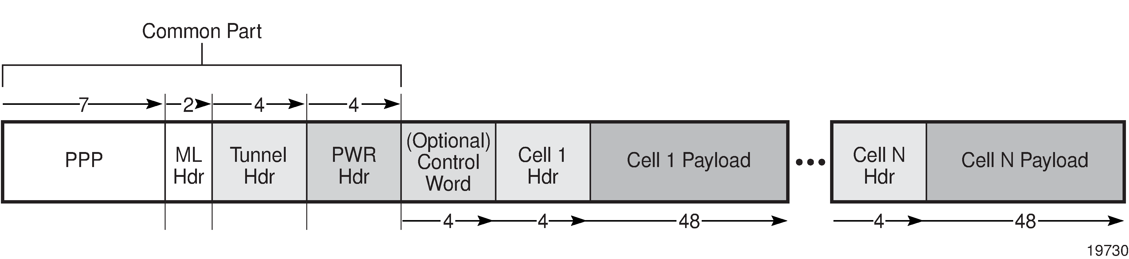
N-to-1 Cell Mode Encapsulation (N = 1)
The following sections describe ATM cell mode encapsulation where N = 1.
Deployment Scenario for N = 1 Cell Mode Encapsulation
In a typical network multiple cell sites are aggregated to individual 7705 SAR nodes. Each cell site has one or more Node Bs. The Node Bs are typically from the same vendor and deployed on a regional basis, and it is common for carriers to simplify provisioning by using the same VPI and VCI values for specific types of traffic handled at different cell sites.
Such a scenario applies, for example, to a service provider that deploys multiple Node Bs in a specific region to support voice, low-speed, and high-speed packet data. In this case, the 7705 SAR grooms the three traffic types from each of the node Bs onto the network. Each traffic type is transported over a dedicated VC as follows:
circuit-switched VC for voice services
packet-switched VC for low-bandwidth data services
HSxPA VC for high-bandwidth data services
In this N-to-1 scenario where N = 1, three VCs and three ATM PWs are required for each Node B.
VPI/VCI Translation (N = 1)
Before traffic from different cell sites can be switched to an RNC, VPI and VCI translation may be required in order to uniquely identify the site and the far-end equipment. If overlapping VPI/VCI values, as described in Deployment Scenario for N = 1 Cell Mode Encapsulation, are not used, VPI/VCI translation is not necessary.
The endpoints of a PWE3 N-to-1 cell mode ATM VLL can be:
ATM VCs—VPI/VCI translation is supported
In this case, when the VPI/VCI used at the endpoints (NodeB endpoint and RNC endpoint) are different, the VPI/VCI value can be modified at the endpoint of the far-end PE node, before the cells are switched to the ATM interface.
ATM VPs—VPI translation is supported (the VPI at each endpoint need not be the same, but the original VCI will be maintained)
In this case, when the VPI and VCI used at the endpoints are different, only the VPI can be modified at the endpoint (VPI can only be changed by the far-end PE node, before the cells are switched to the ATM interface).
See VPI/VCI Translation for SAP Aggregation Group Members (N>1) for information about how VPI/VCI translation functions with N > 1 mode.
Cell Concatenation (N = 1)
The 7705 SAR supports the concatenation of ATM VP and VC cells into a pseudowire packet payload. Cells are packed on ingress to the VLL and unpacked on egress.
The number of cells in the payload of a single VLL packet is user-configurable, which ensures proper transport of traffic sensitive to delay and jitter. For example, for voice traffic in 3G/WCDMA, delay is a crucial factor and the time spent for concatenation should be minimized. The payload is extremely delay-sensitive and should be transported with only a small amount of bandwidth optimization.
In all cases, the number of cells in a VLL packet must be less than the MTU size, where the MTU maximum is 1514 bytes and the maximum N-to-1 mode payload is 29 cells (52 ATM bytes per cell (no HEC byte)).
While cells are being packed, the concatenation process may be terminated and the packet sent by any one of the following conditions. Each condition has a configurable attribute associated with it:
reaching a maximum number of cells per packet
expiring of a timer
changing of the cell loss priority (CLP) bit
The CLP bits are untouched, even if VPI/VCI translation occurs at egress.
QoS and Traffic Descriptor Profiles (N = 1)
QoS is configured on individual SAPs at ingress and egress using the SAP configuration hierarchy.
Individual SAPs support VC-based characteristics that include ingress and egress ATM (Layer 2) traffic descriptor profiles. Apipe rate-limiting on egress is controlled by the traffic-descriptor profile, not the QoS policy queue rates.
OAM (N = 1)
The ATM PW N-to-1 mode supports OAM operations in non-terminating mode for N = 1 services. The far-end PE node translates the incoming VPI/VCI values of the ATM OAM cells in the same way as the user data cells.
N-to-1 Cell Mode Encapsulation (N > 1)
The following sections describe ATM cell mode encapsulation where N > 1.
Deployment Scenario for N > 1 Cell Mode Encapsulation
N-to-1 mode where N >1 can be used by wireless service providers to optimize the PWs that are deployed in a network. By multiplexing the VCs of the same type that derive from different ATM base stations (Node Bs), the number of PWs can be decreased to one PW per service type.
With N-to-1 cell mode encapsulation where N > 1 traffic with the same characteristics and QoS requirements (such as delay, jitter, and loss) can be carried over the payload of a single ATM PW.
VCC Cell Mode Encapsulation with N > 1 shows a typical network where N > 1 is deployed.
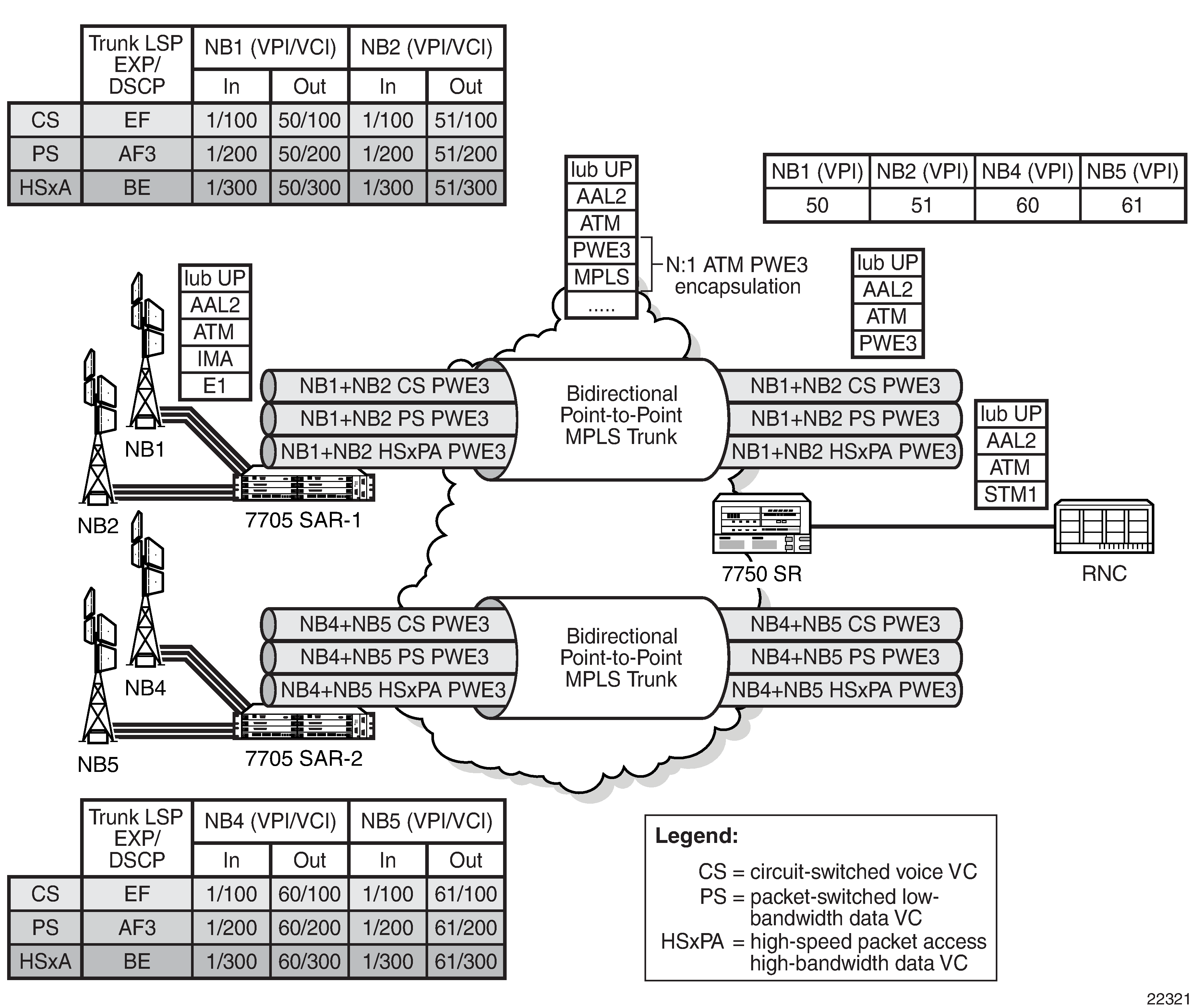
PW Optimization (N > 1)
A network that uses a single PW for each type of traffic significantly reduces the number of ATM PWs that need to be configured to groom the traffic from multiple Node Bs. The result is a more efficient network backhaul configuration and traffic management strategy.
Overhead Optimization (N > 1)
A VC carrying signaling information between a Node B and an RNC must be configured with minimal packetization delay. N-to-1 cell mode encapsulation where N > 1 can be employed to:
optimize the overhead associated with ATM PW headers because one PW packet header is used to transport multiple cells
improve performance for delay and throughput efficiency
Typically, operators configure packetization delay to be 1 ms. Every 1 ms, an ATM PW packet is required to switch the signaling information from the 7705 SAR to the 7750 SR—regardless of the number of ATM cells that are received to transport signaling information. In most cases, the ATM PW packet carries very few ATM cells.
When signaling VCs from multiple Node Bs are mapped to the same ATM PW in N-to-1 fashion, the number of ATM cells that are received every 1 ms potentially increases. For example, if signaling from five Node Bs is aggregated for each ATM PW, a much larger number of ATM cells can be transported per ATM PW header.
Cell Concatenation (N > 1)
The maximum N-to-1 mode payload is 29 cells for N-to-1 cell mode where N > 1. This value applies to all of the SAPs that are members of the same SAP aggregation group. When the cell concatenation is configured for a specified number of cells, the 7705 SAR counts the cells it has received from all of the SAPs in the same SAP aggregation group and transmits the ATM PW packet when the limit is reached.
For example, for an ATM N >1 VCC service with four SAPs bound to the same SAP aggregation group, where the maximum number of cells for cell concatenation is set to 10, SAP1 might have 2 cells, SAP2 might have 5 cells, SAP3 might have 0 cells, and SAP4 might have 3 cells.
In all cases, the number of cells in a VLL packet must be less than the MTU size, where the MTU maximum is 1514 bytes and the maximum N-to-1 mode payload is 29 cells (52 ATM bytes per cell (no HEC byte)).
The max-delay configuration also applies at the SAP aggregation group level.
OAM (N > 1)
The ATM PW N-to-1 mode supports OAM operations in non-terminating mode for N > 1 services. The 7705 SAR forwards the Layer 2 AIS cells that it receives from the SAP aggregation group SAPs over the PW. The 7705 SAR translates the incoming VPI/VCI values of the AIS cells in the same way as any other type of traffic.
Hardware Support for N > 1 Cell Mode Encapsulation
The following hardware supports N > 1 cell mode encapsulation:
16-port T1/E1 ASAP Adapter card
32-port T1/E1 ASAP Adapter card
7705 SAR-M (variants with T1/E1 ports)
SAP Support for N > 1
The SAP aggregation group can include SAPs on:
different ATM ports
different IMA ports
a combination of ATM and IMA ports
SAP Aggregation Groups
N > 1 cell mode encapsulation is implemented on the 7705 SAR using SAP aggregation groups. The following sections describe how to configure and manage SAP aggregation groups:
See Apipe Service with SAP Aggregation Configuration Commands for more information about the commands and parameters that are required to configure a SAP aggregation group.
Configuration
The following section describes the objects required to configure a SAP aggregation group and group members. See VLL Services Configuration Commands for more information.
Sap-aggregation-group Keyword
The sap-aggregation-group keyword is used to associate multiple SAPs with a single ATM VCC Apipe service. The SAP aggregation group is a high-level object under which general features are defined. These features include accounting, statistics, and the packet layer QoS profile. All common access parameters are configured under the sap-aggregation-group.
Sap-aggregation-group Group Identifier
The sap-aggregation-group group-id is used for two purposes:
to identify a SAP aggregation group. The group-id is an alphanumeric identifier. For example:
sap-aggregation-group group_id_1
to identify a SAP as a member of an aggregation group. SAPs that are to be bound to the same ATM PW payload must be tagged with the same sap-aggregation-group group-id. For example:
sap 1/2/3.1:3/300 sap-aggregation-group group_id_1
The sap-aggregation-group group-id can be up to 32 alphanumeric characters.
VPI/VCI Translation for SAP Aggregation Group Members (N>1)
The vcid-translation vpi/vci keyword is an optional configuration item that is used only for SAPs that are members of a SAP aggregation group. The vcid-translation vpi/vci keyword translates the VPI and VCI values of the incoming ATM cells before the cells are mapped to an ATM PW payload. That is, at ingress, the VPI/VCI values for a SAP that is a member of a SAP aggregation group are rewritten by the VPI/VCI values of the vcid-translation keyword.
In the reverse direction, when the 7705 SAR receives the cells with translated VPI/VCI values from its peer (such as a 7750 SR), another translation to SAP-configured VPI/VCI values is required before cells are sent to the SAP.
The vcid-translation keyword applies to user and OAM cells. When the vcid-translation keyword is configured, all cells are translated.
If the vcid-translation keyword is not configured for any ATM SAP aggregation group, the ingress VPI/VCI values are retained.
QoS and Traffic Descriptor Profiles (N > 1)
Packet layer, N > 1 ATM PW QoS functions are configured using the SAP aggregation group hierarchy. The QoS profiles for ingress and egress are configurable for each N > 1 service. Any existing QoS profile can be applied to an N > 1 service. The QoS policy determines the QoS offering, including the classification and queuing for the whole PW, irrespective of the number of SAPs that are bound to the aggregated service.
Although a single SAP egress policy is configured for a SAP aggregation group, a separate egress queue is created for each SAP. The MBS and CBS values for each of these egress SAP queues are set to equal the MBS and CBS values configured in the SAP egress QoS policy for the SAP aggregation group. The SAP egress QoS policy causes n times the values of the CBS buffers to be committed, where n is the number of SAPs in the SAP aggregation group. See the 7705 SAR Quality of Service Guide for more information.
Rate-limiting on egress for aggregated SAPs is controlled by the ATM traffic-descriptor profile, not the QoS policy queue rates. Each SAP that is a member of a SAP aggregation group has its own egress Layer 2 traffic descriptors. These descriptors are used for shaping and scheduling priority at egress.
Statistics and Counters
The statistics for aggregation groups are maintained on a per-group basis. Statistics for SAP aggregation groups are available using the following commands:
show service id n sap-aggregation-group group-id stats
show service id n sap-aggregation-group group-id group-stats
The stats keyword shows statistics for the aggregation group on a per-queue basis. The group-stats keyword shows the SAPs that are members of a specified group and the corresponding SAP-level statistics, including aggregated queue statistics. See Show Commands for more information.
Because SAP aggregation groups can span multiple ports, the 7705 SAR does not support port-level packet and discard counters for N > 1 SAPs. When only N > 1 services are configured on an adapter card, the 7705 SAR shows a value of 0 for port packet and discard statistics.
Octet counters are available under each SAP group member. The port and bundle ATM PVC statistics are recorded for the SAPs in a SAP aggregation group. These statistics are helpful for debugging an individual SAP.
A statistics counter tracks all unconfigured or unknown VPI/VCI values that are received in an ATM PW payload from the network. The received VPI/VCI values are compared to the vcid-translation vpi/vci keyword values, and if a value is detected that does not match, the counter for unknown VPIs/VCIs is incremented. The values appear in the Dropped Egress Cells (unconfigured vpi/vci) field and are available using the show service id n all and show service id n sap-aggregation-group group-id detail commands. See Show Commands for more information.
The monitor service id n sap-aggregation-group group-id command provides user-configurable controls for the interval and rate of statistics collection. See the 7705 SAR Basic System Configuration Guide for more information.
Statistics are cleared using the clear service statistics sap sap-id and clear service statistics sap-aggregation-group group-id commands. The sap sap-id clears ATM Layer 2 counters; QoS counters are not applicable for SAPs that are members of an aggregation group. The sap-aggregation-group group-id clears network Layer 3 QoS queue statistics. See Clear Commands for more information.
Fault Management
A PW failure results in the transmission of a pw-status TLV message to the far-end node. If the 7705 SAR receives a pw-status TLV message, the 7705 SAR sends an AIS to all of the ATM SAPs.
If an individual SAP in a SAP aggregation group of an N > 1 service fails or is disabled, the 7705 SAR inserts OAM cells into the PW for the failing VC, using the translated VPI/VCIs. If all SAPs in a SAP aggregation group fail or are shut down, the 7705 SAR generates a pw-status TLV message that designates the SAP as sap-down.
In the case of a card failure for N = 1 and N > 1 services, if all the SAPs of the same service fail or if the service is shut down, the 7705 SAR transmits a pw-status TLV message to the far-end node. If the 7705 SAR receives a pw-status TLV from the far-end node (that is, a lacIngressFault or lacEgressFault), AIS messages are generated and sent to all of the SAPs that are part of the SAP aggregation group.
If a port fails, the 7705 SAR sends AIS cells over the ATM PW to the far-end node.
For end-to-end resiliency, an N > 1 ATM PW service supports PW redundancy.
QoS Policies
When applied to 7705 SAR Apipe, Cpipe, Epipe, and Ipipe services, service ingress QoS policies only create the unicast queues defined in the policy.
With Apipe, Cpipe, Epipe, and Ipipe services, egress QoS policies function as with other services where the class-based queues are created as defined in the policy.
Both Layer 2 and Layer 3 criteria can be used in the QoS policies for traffic classification in a Cpipe, Epipe, or Ipipe service. QoS policies on Apipes cannot perform any classification.
IP Filter Policies
The 7705 SAR supports IPv4 and IPv6 filter policies on the following entities:
IPv4 ingress
network interfaces
Ethernet SAPs on all services
ATM SAPs on a 4-port OC3/STM1 Clear Channel Adapter card in conjunction with bridged llc-snap ATM SAP to VPLS
ATM SAPs on a 16- or 32-port T1/E1 ASAP Adapter card in conjunction with routed VC-Mux ATM SAP to IES
FR and cHDLC SAPs on a 16- or 32-port T1/E1 ASAP Adapter card in conjunction with IP PWs
FR SAPs on a 4-port DS3/E3 Adapter card in DS3, clear channel mode in conjunction with IP PWs
V.35 and X.21 cHDLC SAPs on a 12-port Serial Data Interface card in conjunction with IP PWs
spoke SDPs on VPLS, VPRN interfaces, and IES interfaces
mesh SDPs on VPLS
IPv4 egress
network interfaces
Ethernet SAPs on VPRN and IES interfaces
Ethernet SAPs on VPLS
IPv6 ingress and egress
Ethernet network interfaces (with null or dot1q encapsulation)
network interfaces on the 4-port OC3/STM1 Clear Channel Adapter card (with POS encapsulation)
Ethernet SAPs on IES
Configuration and assignment of IP filter policies is similar for network interfaces, IES management SAPs, Ethernet and IP pseudowire SAPs, VPRN and IES SAPs and spoke SDPs, and VPLS SAPs and SDPs (spoke and mesh). See the 7705 SAR Router Configuration Guide, ‟Filter Policies”, for information about configuring IP filters.
MTU Settings
There are several MTU values that must be set properly for a VLL service (Apipe, Cpipe, Epipe, Fpipe, Hpipe, or Ipipe) to work from end to end. MTU Points on the 7705 SAR locates the MTU point for each value. MTU Points and Descriptions describes the MTU points. The MTU points are:
access port MTU
SAP MTU
service MTU
path MTU
network port MTU
In order for a VLL service to be declared ‟up” without any MTU-related error messages, the following rule must be true:
SAP MTU ≥ Service MTU ≤ Path MTU
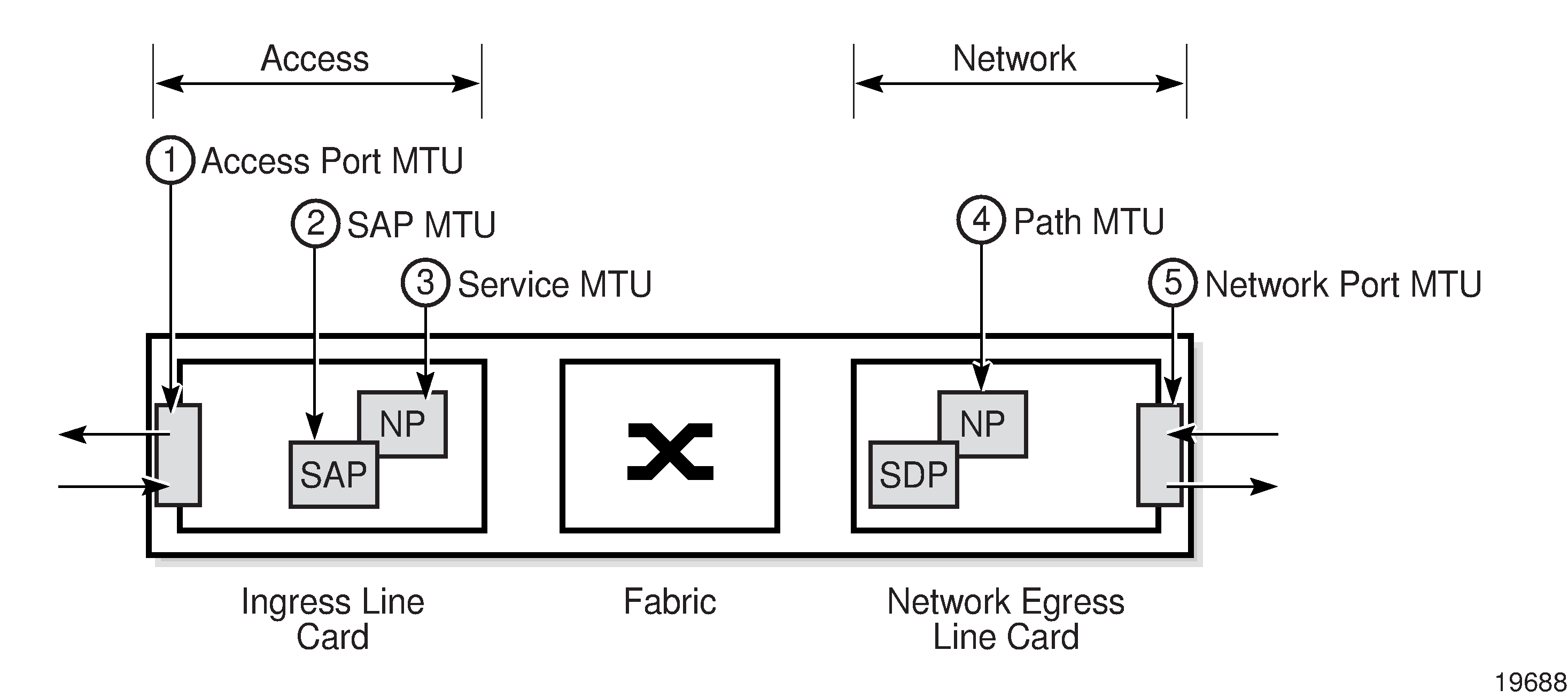
MTU Point |
Description |
Command |
|
|---|---|---|---|
1 |
Access port MTU |
The access port MTU value is a configurable value that accounts for the Layer 2 header and the payload. The default access port MTU value for the following Fast Ethernet port SAP encapsulations is:
|
mtu, under the config>port context, where the port type can be Ethernet, TDM, serial, or SONET/SDH |
2 |
SAP MTU |
The SAP MTU value is not a configurable value. It is set at the SAP by the 7705 SAR operating system. It defines the service payload capability of the service and is automatically set to be the same value as the access port MTU. |
Not user-configurable |
3 |
Service MTU |
The service MTU value is a configurable value and is the same size as the VLL payload. The service MTU is sometimes called the VC-type MTU in the 7705 SAR documentation set. In MTU Points on the 7705 SAR, NP stands for network processor. For CESoPSN with CAS service, ensure that the service MTU is set to a value large enough to account for the extra bytes appended to the packet payload for CAS bits. See Structured T1/E1 CES with CAS for more information. |
service-mtu, under the config>port context, where the port type can be Ethernet, TDM, serial, or SONET/SDH |
IP MTU is specific to Layer 3 spoke-SDP termination. Layer 3 spoke-SDP termination can be configured for interfaces under IES and VPRN services. IP MTU is used to signal the service MTU of Layer 3-spoke SDP termination to a peer PE node. |
ip-mtu, under the config>service> vprn or ies context for an interface |
||
4 |
Path MTU |
The path MTU is configured at the SDP. It is the maximum that the SDP can transmit without rejecting and discarding the packet. The path MTU value is derived from the network port MTU value by subtracting the Layer 2 and Layer 2.5 overhead values (for MPLS) and the Layer 2 and Layer 3 overhead values (for GRE). If the network port SDP binding is Ethernet, then the following equations hold:
|
path-mtu, under the config> service>sdp context |
5 |
Network port MTU |
The network port MTU is a configurable value equal to the payload plus all headers (L2, IP (for GRE), tunnel and PW), up to the maximum supported value (hardware limit) of 9728 bytes. |
Same as access port MTU (above) |
Service MTU Default and Maximum Values displays the default, minimum, and maximum service MTU values for Ethernet ports. These values are dependent upon the port type, mode, encapsulation type, and service type.
MTU Calculator—Service Creation (Worst Case) Access Ports and SAPs and MTU Calculator—Service Creation (Worst Case) Network Ports aid in calculating MTU values for various configurations and operating scenarios.
Port Type |
Mode |
Encap Type |
Service Type |
Service MTU (bytes) |
|||
|---|---|---|---|---|---|---|---|
Default |
Minimum |
Maximum (SAP to SDP) |
Maximum (SAP to SAP) |
||||
10/100 Ethernet 1 |
Access |
null, dot1q, qinq 2 |
Epipe, VPLS |
1514 |
1 |
9670 3 |
9724 3 |
Ipipe |
1500 |
||||||
GigE SFP 1 |
Access |
null, dot1q, qinq 2 |
Epipe, VPLS |
1514 |
1 |
9670 3 |
9724 3 |
Ipipe |
1500 |
||||||
Notes:
The maximum MTU value is supported only on cards that have buffer chaining enabled.
-
QinQ is supported only on access ports.
On the Packet Microwave Adapter card, the MWA ports support 4 bytes less than the Ethernet ports. MWA ports support a maximum MTU of 9720 bytes (null) or 9724 bytes (dot1q). MWA ports do not support QinQ.
For more information about port MTU, see ‟MTU Configuration Guidelines” in the 7705 SAR Interface Configuration Guide.
Service Creation |
|||||||||
|---|---|---|---|---|---|---|---|---|---|
Access Port Default MTU |
SAP |
||||||||
TDM/ATM |
Eth |
Epipe |
Ipipe |
Apipe |
Cpipe |
Fpipe |
Hpipe |
||
Max Payload |
9732 |
9732 |
1514 |
1514 |
2048 |
2048 |
|||
RTP Header |
12 |
||||||||
Control Word |
4 |
4 |
4 |
4 |
4 |
4 |
|||
SDP Encap: GRE/MPLS |
IP Header for |
20 |
20 |
20 |
20 |
20 |
20 |
||
GRE/MPLS |
4 |
4 |
4 |
4 |
4 |
4 |
|||
PW Header |
4 |
4 |
4 |
4 |
4 |
4 |
|||
VCCV Type 2 |
4 |
4 |
4 |
4 |
4 |
4 |
|||
Fast Reroute Label |
|||||||||
LDP over RSVP |
|||||||||
Physical Media (T1/E1 ASAP and Ethernet Adapter cards) |
Eth Null |
1514 |
|||||||
Eth Dot1q |
1518 |
||||||||
Eth QinQ |
1522 |
||||||||
Eth Type |
|||||||||
Eth-SA |
|||||||||
Eth-DA |
|||||||||
TDM/ATM |
1572 |
1572 |
|||||||
PPP Protocol |
|||||||||
ML Sequence |
|||||||||
ML Preamble |
|||||||||
Total |
9768 |
9768 |
1550 |
1562 |
2084 |
2084 |
|||
Service Creation |
NW |
||||||||
|---|---|---|---|---|---|---|---|---|---|
Network Port Default MTU |
|||||||||
Epipe over MPLS Encap |
Epipe/Ipipe over GRE |
LSR |
|||||||
PPP |
ML/PPP |
Eth Null |
Eth Dot1q |
MPLS Label |
Best Case |
Worst Case |
Worst Case |
||
Max Payload |
40 |
2048 |
2084 |
||||||
RTP Header |
|||||||||
Control Word |
4 |
||||||||
SDP Encap: GRE/MPLS |
IP Header for |
20 |
|||||||
GRE/MPLS |
4 |
4 |
4 |
||||||
PW Header |
4 |
4 |
|||||||
VCCV Type 2 |
4 |
4 |
|||||||
Fast Reroute Label |
4 |
||||||||
LDP over RSVP |
4 |
||||||||
Physical Media (T1/E1 ASAP and Ethernet Adapter cards) |
Eth Null |
||||||||
Eth Dot1q |
4 |
4 |
4 |
||||||
Eth QinQ |
8 |
8 |
8 |
||||||
Eth Type |
2 |
2 |
2 |
2 |
|||||
Eth-SA |
6 |
6 |
6 |
6 |
|||||
Eth-DA |
6 |
6 |
6 |
6 |
|||||
TDM/ATM |
|||||||||
PPP Protocol |
2 |
2 |
2 |
||||||
ML Sequence |
3 |
||||||||
ML Preamble |
1 |
||||||||
Total |
2 |
6 |
14 |
26 |
50 |
2110 |
2114 |
||
In order to accommodate current and future services (including overhead), the MTU values for Gigabit Ethernet and PPP/MLPPP ports have the default value set to 1572 bytes. For 10/100 Ethernet ports, the MTU value is set to 1514 or 1518 or 1522 bytes, depending on the encapsulation setting (null or dot1q or qinq).
The default service MTU value is 1514 bytes; the maximum value is 1522 bytes.
Targeted LDP and MTU
The extended discovery mechanism for Label Distribution Protocol (LDP) sends LDP Targeted Hello messages to a specific address. This is known as targeted LDP or T-LDP. See RFC 5036 for detailed information about the extended discovery mechanism.
During the VLL service creation process (that is, using targeted LDP signaling), the MTU or payload size of a service is signaled to the far-end peer. MTU settings at both ends (near and far peers) must match in order for the VLL service to operate. Matching MTU or Payload Values for Signaled VLL Services shows the values that are expected to match.
Apipe |
Cpipe |
Epipe |
Fpipe |
Hpipe |
Ipipe |
|
|---|---|---|---|---|---|---|
Payload size (bytes) |
Yes |
|||||
Bit rate |
Yes |
|||||
Maximum number of ATM cells |
Yes |
|||||
Service MTU |
Yes |
Yes |
Yes |
Yes |
||
Must match at both ends |
Yes |
Yes |
Yes |
Yes |
Yes |
Yes |
QinQ (VLL Service)
Epipe and Ipipe VLL services support QinQ functionality. For details, see QinQ Support.
Pseudowire Control Word
The PW control word (CW) is a 32-bit field that is inserted between the VC label and the Layer 2 frame. The presence of the control word is indicated by the C bit of the FEC element used in LDP signaling. The PW control word is described in RFC 4385.
The PW control word is supported for all implemented PW types:
Apipes (ATM VLLs)
Epipes (Ethernet VLLs)
Cpipes (TDM VLLs in SAToP and CESoPSN circulation emulation mode)
Fpipes (frame relay VLLs in one-to-one mapping mode)
Hpipes (HDLC VLLs)
Ipipes (IP interworking VLLs)
For Apipes, the control word is optional. It can be enabled to guarantee ordered packet/cell delivery.
For Epipes (with the exception of MEF 8 services) and Ipipes, the control word is optional. If it is enabled, it will be set to all zeros and ignored on egress.
For Cpipes, Epipe MEF 8 services, and Fpipes, the control word is mandatory and cannot be configured.
For Hpipes, the control word is optional when transporting packets that are more than 64 bytes but mandatory when transporting packets that are less than 64 bytes.
When the packet length is less than 64 bytes (that is, the length of the Layer 2 payload plus the length of the control word), the length field in the control word is set to the length of the packet. Otherwise, the length field is set to 0. The CE-bound PE uses the length field in the control word to determine the size of the padding that was added by the PSN so that the PE can extract the PW payload from the PW packet. If the control word is not set for packets less than 64 bytes, the PE cannot determine the original length of the packet and will forward the payload, including the padding bits. On reception of the padded packet, the CE will drop the packet.
The following points describe the behavior of the 7705 SAR when it receives a Label Mapping message for a PW. It is assumed that no Label Mapping message for the PW has been sent to the next PW router yet. The 7705 SAR operating system does the following.
If the received Label Mapping message has C = 0 (where C refers to the C bit of the FEC element), a Label Mapping message with C = 0 is sent forward to the next router (or hop). In this case, the control word is not used.
If the received Label Mapping message has C = 1 and the PW is locally configured such that the use of the control word is mandatory, then the 7705 SAR sends a Label Mapping message with C = 1. In this case, the control word is used. (Note: SAToP and CESoPSN (Cpipes), Epipe MEF 8 services, and Fpipes always require the control word.)
If the received Label Mapping message has C = 1 and the PW is locally configured such that the use of the control word is not supported, the 7705 SAR sends a new Label Mapping message in which the C bit is set to correspond to the locally configured preference for use of the control word (that is, C = 0).
Pseudowire Redundancy
Pseudowire (PW) redundancy protects a PW and any services on the PW against endpoint failures. This differs from LSP redundancy and FRR, which offer protection against link and node failures within the backhaul network.
As shown in Pseudowire Redundancy, in order to provide redundant PWs, the 7705 SAR must signal PWs to two endpoints at the MTSO (7x50-1 and 7x50-2), which is done using two spoke SDPs on the 7705 SAR. This configuration removes any single point of failure from a given network. If 7x50-1 loses all of its connectivity to the network or to the RNC, the 7705 SAR can reroute the PW traffic to 7x50-2, which switches traffic to the RNC.
For end-to-end protection, PW redundancy is supported in the following scenarios:
PW redundancy with multi-chassis LAG (MC-LAG), multi-chassis APS (MC-APS), and T1/E1 multi-chassis line card redundancy (MC-LCR)
PW redundancy with VPLS or PW switching
For more information about MC-LAG, see the 7705 SAR Interface Configuration Guide, ‟Multi-Chassis LAG”. For more information about MC-APS, see the 7705 SAR Interface Configuration Guide, ‟Automatic Protection Switching”. For more information about MC-LCR, see the 7705 SAR Interface Configuration Guide, ‟T1/E1 Line Card Redundancy”.
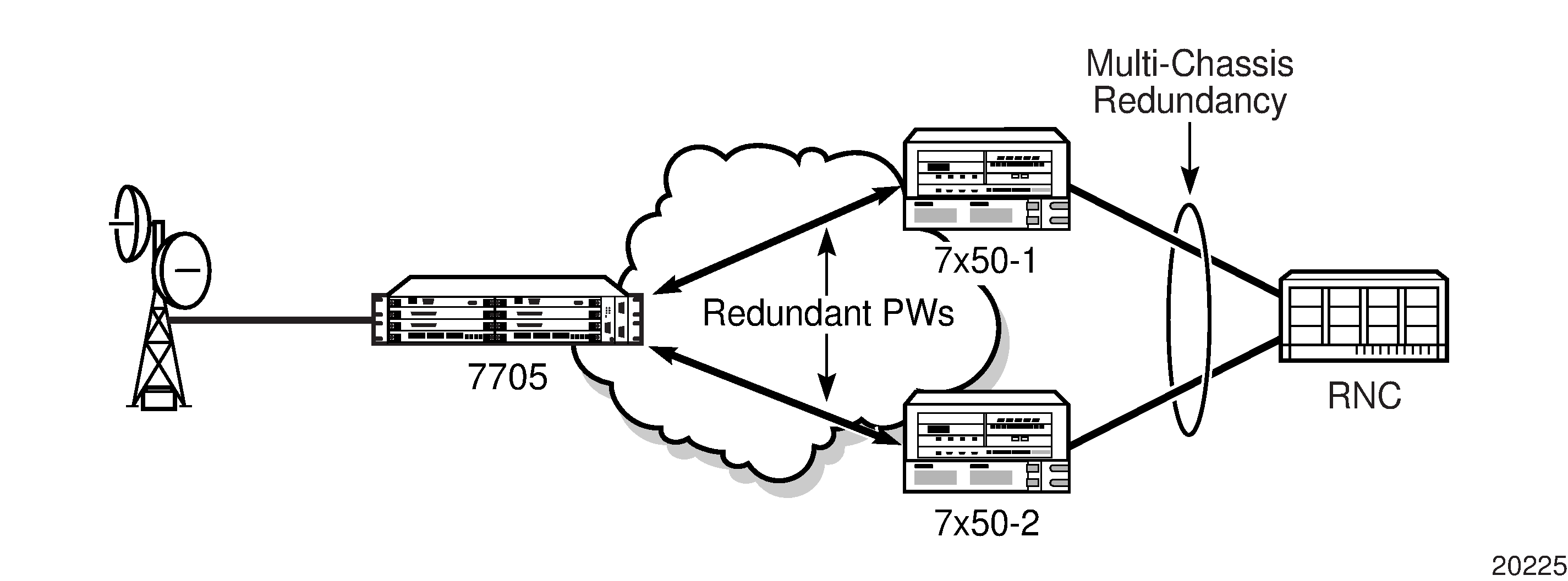
PW redundancy applies to all VLL services available on the 7705 SAR: Apipe, Cpipe, Epipe, Fpipe, Hpipe, and Ipipe.
PW Redundancy Operation
PW redundancy on the 7705 SAR is similar to a point-to-multipoint implementation for PWs (in the ingress to the egress direction). A single SAP can be bound to more than one spoke SDP, and traffic from multiple spoke SDPs can all be switched to the same SAP. To implement PW redundancy, a PW service on the 7705 SAR must be able to accommodate more than one spoke SDP on the spoke SDP side. This is achieved using the concept of endpoints.
An endpoint can be thought of as a container for a single SAP, a single spoke SDP, or multiple spoke SDPs. Implicit and Explicit Endpoint Objects illustrates the model for a redundant VLL service based on the endpoints. Endpoints are implicit or explicit objects.
Implicit endpoints are transparent to the user and are not user-configurable. As shown in Implicit and Explicit Endpoint Objectsa, implicit endpoints mean that one endpoint is a SAP and another endpoint is a spoke SDP. Endpoints are considered implicit if the endpoint command is not used in the config>service>xpipe>spoke-sdp context, where xpipe refers to any of the VLL services.
Explicit endpoints are user-configurable and apply when there are multiple spoke SDPs. As shown in Implicit and Explicit Endpoint Objectsb, explicit endpoints mean that there can be multiple spoke SDPs associated with the endpoint. An endpoint created explicitly can have up to four spoke SDPs associated with it. The explicit endpoint method is used for PW redundancy. Explicit endpoints are user-configurable.
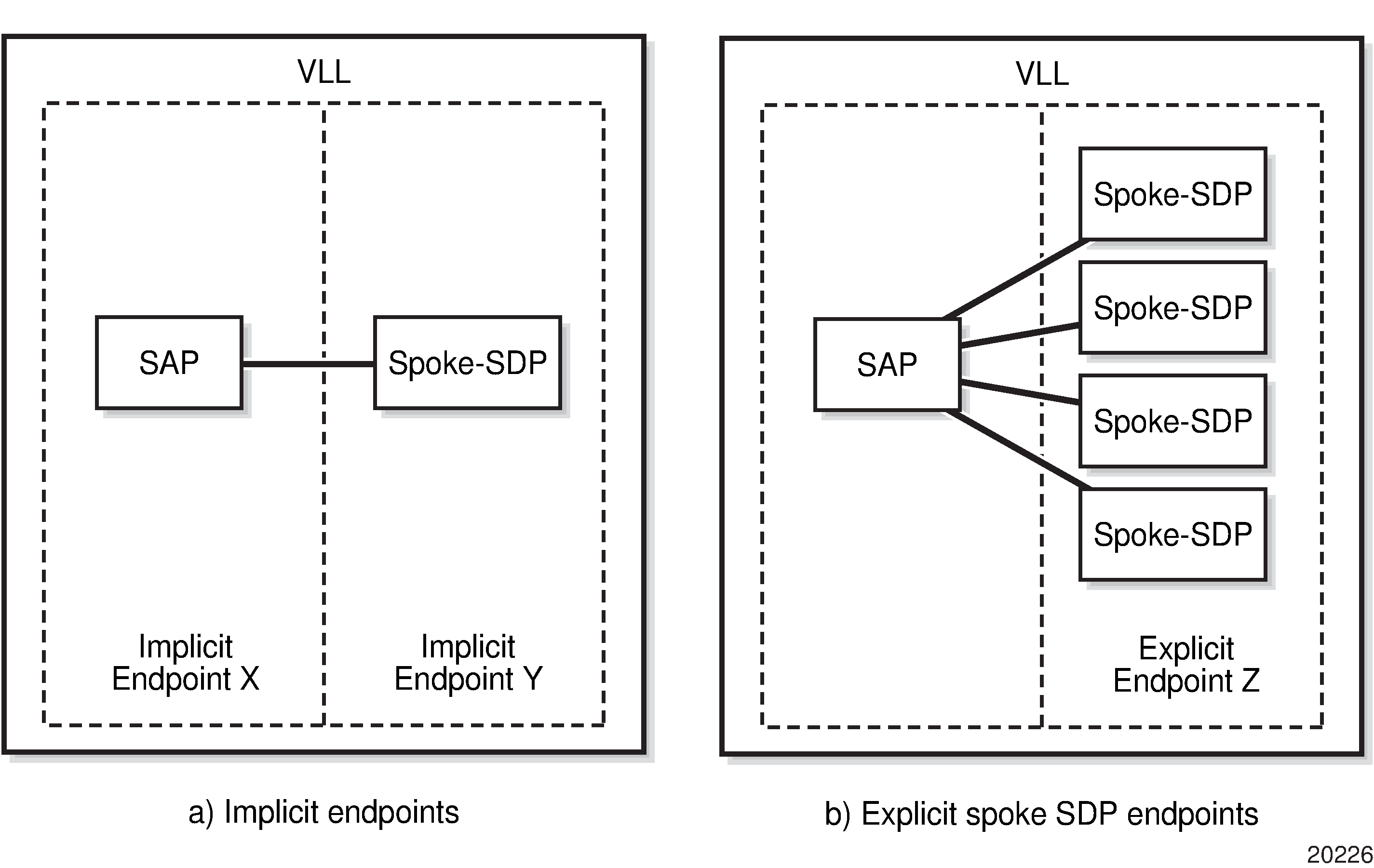
The 7705 SAR supports the following types of endpoint objects:
SAP—there can be only one SAP per PW endpoint (Endpoint X in Implicit and Explicit Endpoint Objectsa)
Spoke SDP—from the perspective of a 7705 SAR, if there is only one SDP endpoint, then it is a spoke SDP endpoint and it is implicitly defined. In other words, there can be only one implicitly defined spoke SDP per PW endpoint (Endpoint Y in Implicit and Explicit Endpoint Objectsa).
Primary spoke SDP—there can be only one explicitly defined primary spoke SDP per PW endpoint (one of the spoke SDPs at Endpoint Z in Implicit and Explicit Endpoint Objectsb). If a primary spoke SDP is defined, then there can be up to three secondary spoke SDPs per endpoint and the service can be revertive.
Secondary spoke SDP—there can be up to four explicitly defined secondary spoke SDPs per endpoint if no primary spoke SDP is defined; otherwise, there can be up to three. Secondary spoke SDPs are assigned a precedence value that is used by the 7705 SAR to determine which secondary PW becomes active when the currently active PW fails (see Selecting the Active Spoke SDP for PW Redundancy Configuration).
Multiple spoke SDPs can be established between a 7705 SAR and any SR platform. For example, multiple spoke SDPs on a 7705 SAR can connect to a 7750 SR. In this case, the 7750 SR must be configured to use multi-chassis backup in conjunction with multi-segment PWs; that is, the 7750 SR nodes at the far end must support multi-chassis redundancy.
A PW service endpoint can only use a single active spoke SDP for transmission at any given time. A PW SAP can receive traffic from any of the endpoint spoke SDPs assigned to the service.
7705 SAR nodes support user-initiated manual switchover of the VLL path to the primary path or any of the secondary paths using the force-switchover command under the tools>perform>service-id context. A manual switchover is useful during planned outages such as node upgrade procedures.
Selecting the Active Spoke SDP for PW Redundancy Configuration
There are two main scenarios for configuring PW redundancy. One scenario uses a primary spoke SDP and provides revertive behavior. The other scenario uses only secondary spoke SDPs for non-revertive behavior.
Primary and Secondary Spoke SDPs
If a primary spoke SDP is defined, up to three secondary spoke SDPs can also be defined. The VLL service always uses the primary endpoint PW and only switches to a secondary PW when the primary PW is down. The PW service switches the path back to the primary PW when the primary PW is back up. The user can configure a timer to delay reverting to the primary path or to never revert to the primary path. When the primary PW goes down, the 7705 SAR selects the secondary spoke SDP that is operationally up and has the highest precedence setting.
Secondary Spoke SDPs Only
If a primary spoke SDP is not defined, up to four secondary spoke SDPs can be defined. The user can configure the precedence of each secondary PW to indicate the order in which secondary PWs are activated. The secondary PW with the highest precedence is selected first. If two or more secondary spoke SDPs are assigned the same precedence, the 7705 SAR selects the secondary path that is operationally up and has the lowest spoke SDP identifier. There is no revertive behavior between secondary paths, which means that a secondary path will not switch to another secondary path of higher precedence if one becomes available.
The use of four secondary spoke SDPs is illustrated in Pseudowire Redundancy with Four Spoke SDPs, where:
spoke SDP-1 goes over S-PE-1 to T-PE1 (red path) (S-PE is a switching PE and T-PE is a terminating PE)
spoke SDP-2 goes over S-PE-1 to T-PE2 (green path)
spoke SDP-3 goes over S-PE-2 to T-PE1 (violet path)
spoke SDP-4 goes over S-PE-2 to T-PE2 (orange path)
.
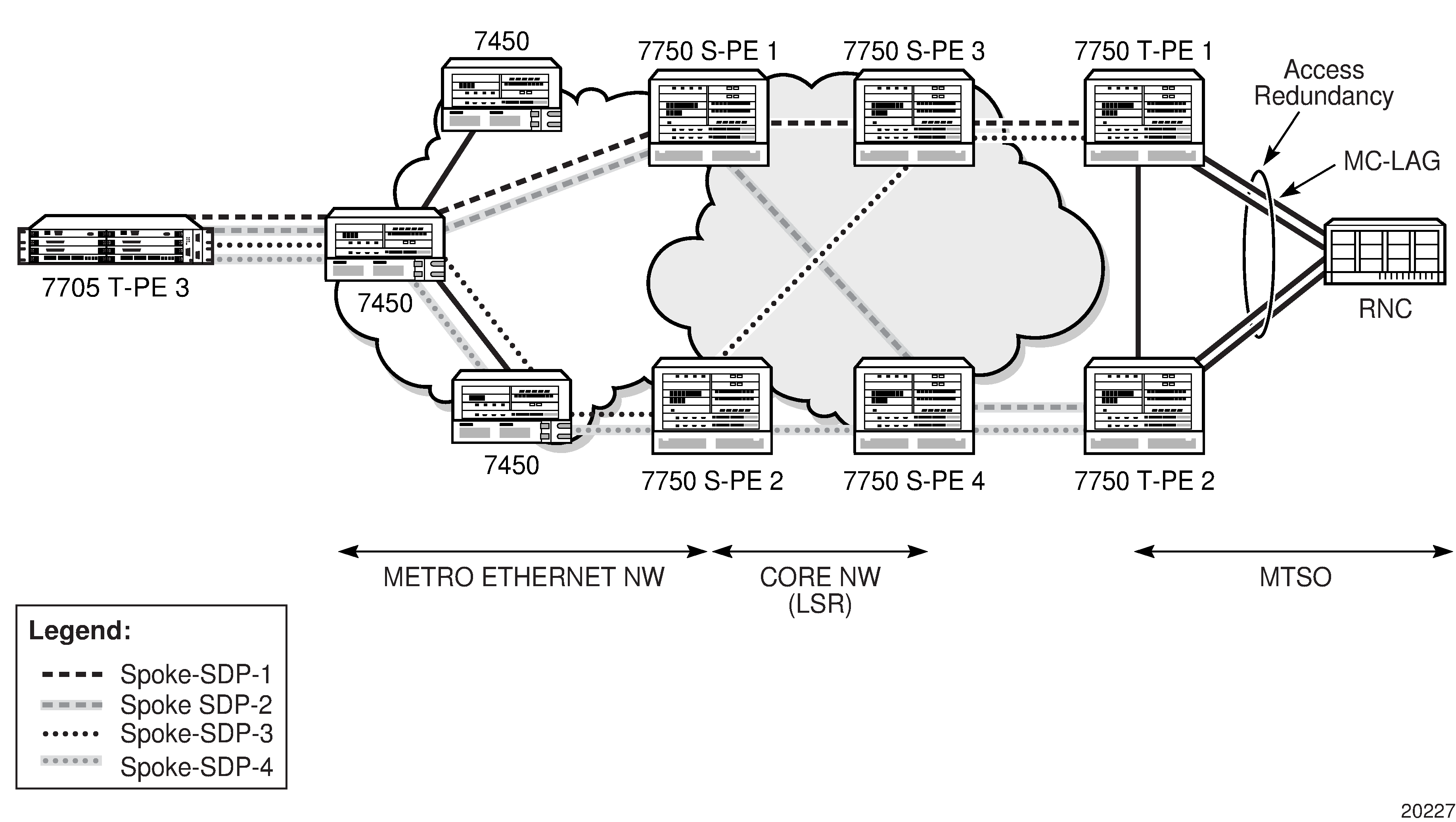
PW Redundancy and Inter-Chassis Backup
Inter-Chassis Backup (ICB) spoke SDPs are supported for use with Cpipe services in an MC-APS or MC-LCR configuration and with Epipe services in an MC-LAG configuration. ICB improves switch times, provides additional protection in case of network failures, and reduces packet loss when an active endpoint is switched from a failed MC-APS, MC-LCR, or MC-LAG node to a protection node.
A failure on the access side triggers an access side MC-APS, MC-LCR, or MC-LAG switchover and a network-side pseudowire switchover. A failure on the network side triggers a pseudowire switchover but does not trigger an MC-APS, MC-LCR, or MC-LAG switchover.
Access Side Failure with ICB Protection shows a network experiencing an access side failure in an MC-LAG scenario.
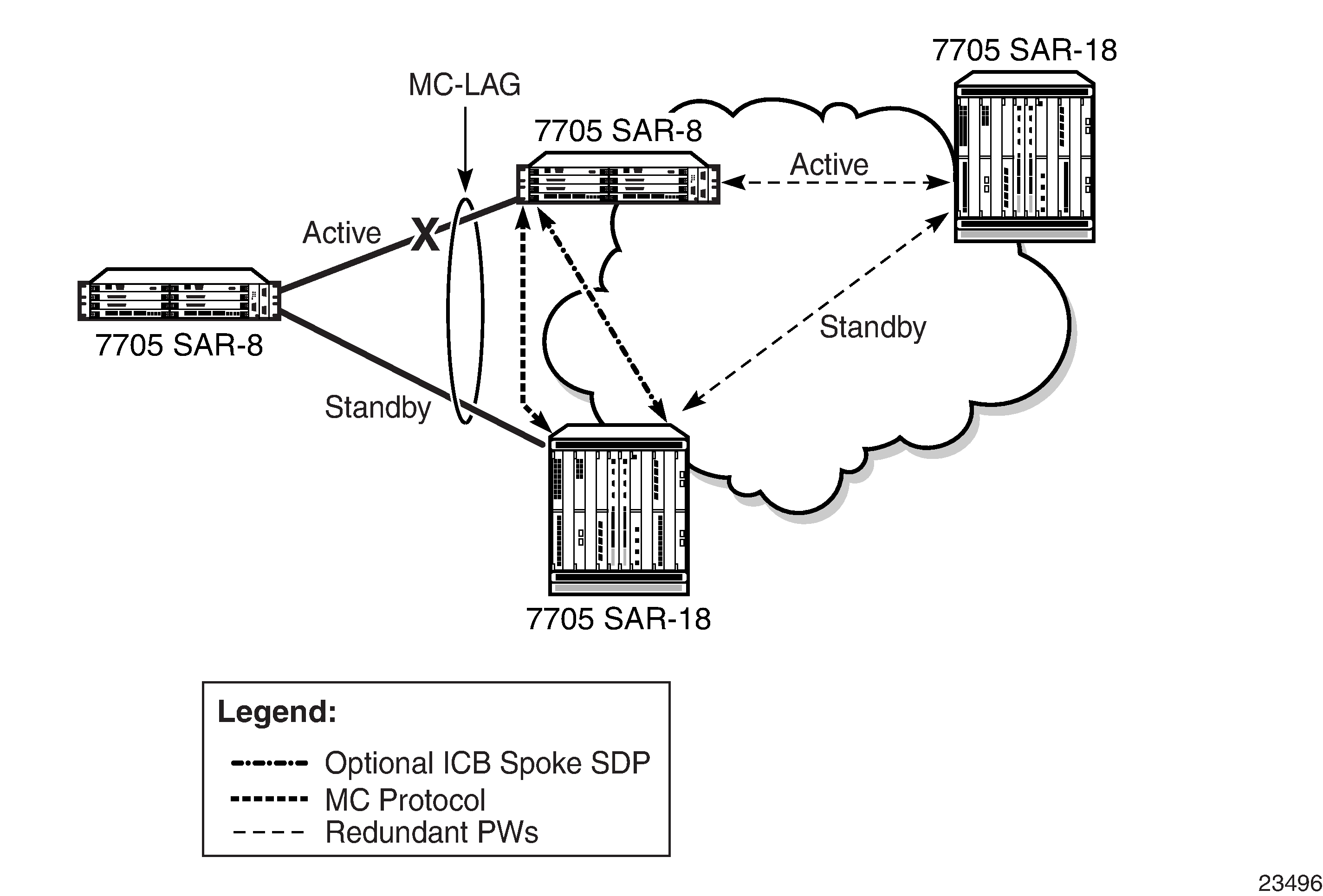
If the active access link of an MC-APS, MC-LCR, or MC-LAG group fails, the MC-APS, MC-LCR, or MC-LAG protocol causes the access side to switch to the protection (standby) link. If ICB is configured, the in-flight packets coming from the network side will be sent over the ICB to the newly active access link. Shortly after the access-side switchover, pseudowire redundancy causes the network side to switch as well. In this scenario, ICB reduces the switch time by carrying the in-flight packets during the access and network switchovers.
Network Side Failure with ICB Protection shows a network experiencing a network side failure in an MC-LAG scenario.

If the active network link of an MC-APS, MC-LCR, or MC-LAG group fails, pseudowire redundancy causes the network side to switch to the standby pseudowire. This does not trigger an MC-APS, MC-LCR, or MC-LAG switchover. If there is no ICB, the end-to-end transmission will be lost because the access link never switches. If ICB is configured, the packets coming in from the newly active network link are sent across the ICB to the active access side and vice versa. In this scenario, ICB provides protection against network failures.
An endpoint can have only one ICB spoke SDP, which must be identified as ICB in the spoke-sdp command. If an ICB spoke SDP is added to an endpoint, a SAP can be added only if it is part of an MC-LAG, MC-APS, or MC-LCR group. Similarly, if an MC-LAG, MC-APS, or MC-LCR SAP is added to an endpoint, the only other possible addition to that endpoint is an ICB spoke SDP.
AIS Fault Propagation
When the 7705 SAR is operating in an MPLS network with TDM pseudowires using PW redundancy, it can interoperate with SDH networks that use subnetwork connection protection (SNCP). SNCP is a path-based protection mechanism for T1/E1 services. When the 7705 SAR interoperates with SDH networks that use SNCP, it can make PW redundancy switching decisions based on SDH signaling, which keeps the active data paths in the SDH and the MPLS networks synchronized.
This functionality is only available on unframed E1 channels and unframed DS1 channels on the following cards:
2-port OC3/STM1 Channelized Adapter card
4-port OC3/STM1 / 1-port OC12/STM4 Adapter card
If SNCP-protected equipment detects a failure in an SDH network, it inserts an AIS into the TU-12 overhead of the SDH frame so that the appropriate activity switch can occur in the SDH network. When the 7705 SAR detects a TU12-AIS for a specific VC-12 path in an SDH network and AIS propagation is enabled using the command config>card>mda>ais-propagation, the 7705 SAR generates a TU12-AIS for the corresponding VC-12 at the other end of the Cpipe. If the VC-12 path is involved in PW redundancy, a PW activity switch occurs, which signals the SDH node to do an SNCP switch.
Active/Standby Mode for Pseudowire Redundancy (Standby Signaling)
Pseudowire redundancy as described in the previous section operates in active/active mode; that is, the primary pseudowire is up and ready to transmit and receive traffic, and the secondary pseudowire is up and ready to receive traffic. In Active/Standby Mode for Redundant Pseudowires, if both pseudowires were active, this mode of operation would offer seamless redundancy in most cases. However, this mode could also potentially stress the IGP; for example, in active/active mode the number of routes advertised is greater than in active/standby mode. Another example is the duplication of Ethernet control frames to the 7705 SAR from a VPLS or VPRN service on an SR node through both primary and secondary VLLs.
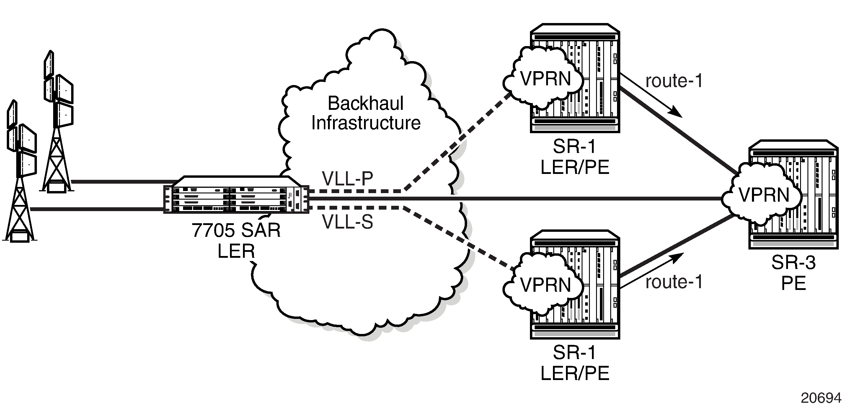
Active/standby mode is introduced to address these issues. Active/standby mode is also referred to as standby signaling. Standby signaling is supported on all VLLs: Apipes, Cpipes, Epipes, Ipipes, Fpipes, and Hpipes.
Standby signaling has two components: standby-signaling master and standby-signaling slave. Standby-signaling-master Enabled shows an example where standby-signaling-master has been enabled on the 7705_MTU node. A Cpipe has been configured between the 7705_MTU and the 7705_A node and between the 7705_MTU and the 7705_B node. The spoke SDP towards 7705_A is the active PW (precedence primary), while the spoke SDP towards 7705_B is the standby PW (precedence 1).
An example of the CLI syntax to configure the 7705_MTU is:
- CLI Syntax:
config>service# cpipe 555 customer 1 vc-type cesopsn createendpoint ‟stdbyMaster” createstandby-signaling-masterexitspoke-sdp 5:555 endpoint ‟stdbyMaster” createprecedence 1exitspoke-sdp 131:555 endpoint ‟stdbyMaster” createprecedence primaryexit
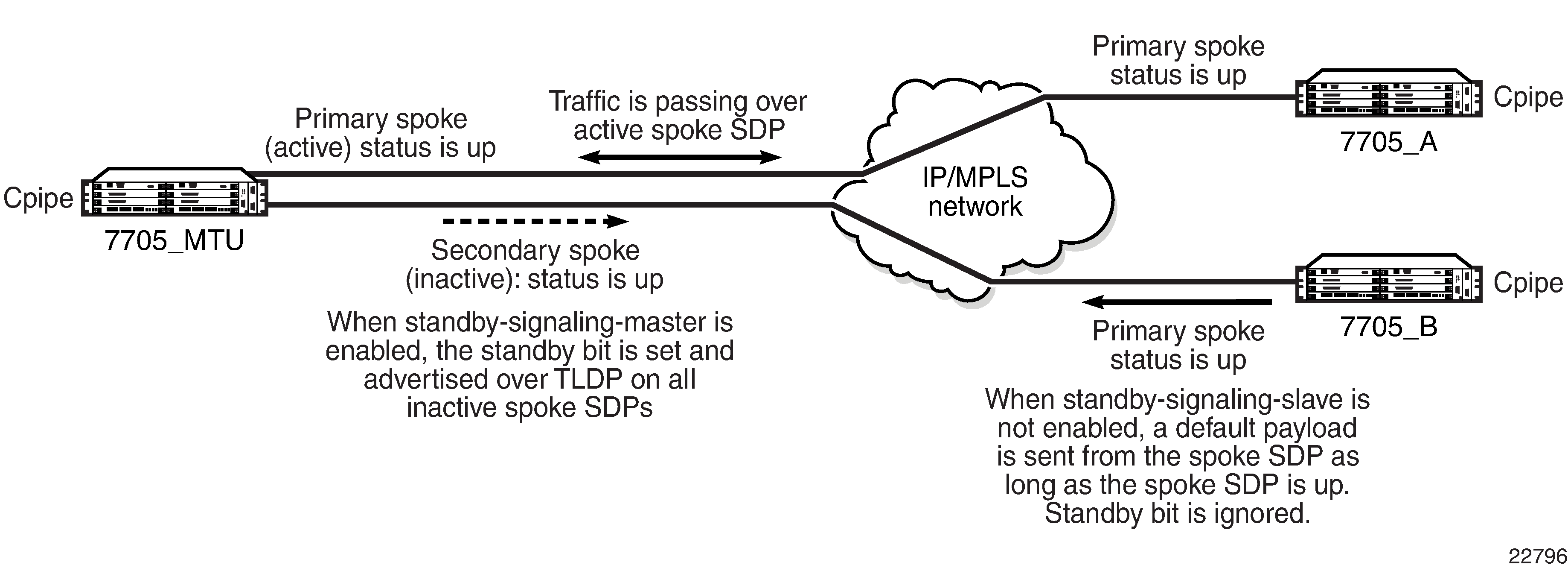
Traffic passes over the active PW. If the status of the active PW changes, the standby PW becomes active and starts passing traffic.
Because the 7705_MTU is configured for standby-signaling-master, the standby PW sends its status to the far end by sending a standby bit over T-LDP. However, the receiving end (in Standby-signaling-master Enabled, 7705_B) ignores the bit and continues to transmit data towards the 7705_MTU as long as the PW is up; therefore, pseudowire redundancy does not work.
In order to stop data from being transmitted along standby spoke SDPs, the far-end endpoints must be enabled for standby-signaling-slave. Standby-signaling-slave Enabled shows a scenario where 7705_A and 7705_B have been enabled for standby-signaling-slave.
An example of the CLI syntax to configure the 7705_A and 7705_B nodes is:
- CLI Syntax:
config>service# cpipe 555 customer 1 vc-type cesopsn createendpoint ‟FarendA” createstandby-signaling-slaveexitspoke-sdp 130:555 endpoint ‟FarendA” createprecedence primaryexit
- CLI Syntax:
config>service# cpipe 555 customer 1 vc-type cesopsn createendpoint ‟FarendB” createstandby-signaling-slaveexitspoke-sdp 130:555 endpoint ‟FarendB” createprecedence primaryexit
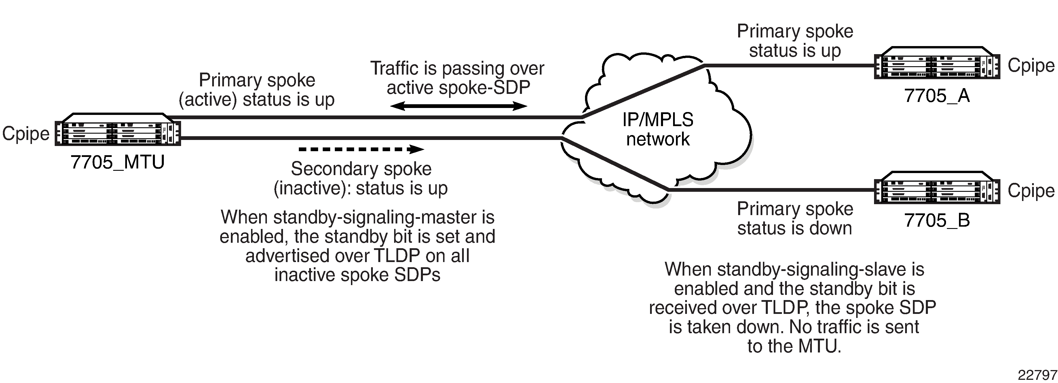
With standby-signaling-slave enabled, when the standby PW sends the standby bit to the far end over T-LDP, the SDP flags bit is set to block traffic being transmitted back to the 7705_MTU (flags bit is set to StandbySigSlaveTxDown). The spoke SDP remains up. If the standby PW becomes active, the flags bit is reset and traffic resumes on the PW.
PW Status Signaling Label Withdrawal Option
The 7705 SAR supports PW status signaling or label withdrawal for signaling PW status.
Signaling PW status based on label withdrawal requires the PW label to be released, whereas PW status signaling can mark the PW as unusable based on local-end and far-end status and on status messages exchanged between endpoints.
As indicated in RFC 4447, Pseudowire Setup and Maintenance Using the Label Distribution Protocol, PW status signaling is the preferred method for exchanging state information between two endpoints and should be used as long as both endpoints support it.
However, the PW label withdrawal method for exchanging PW status can be configured even if the far end supports PW status signaling and the PW status TLV for designating the operational (forwarding) state of a PW.
This configuration option allows the PEs at both ends of the spoke SDP to use PW label withdrawal rather than the PW status TLV. This is necessary when a 7705 SAR must interoperate with PEs that do not support the PW forwarding standby bit, or when multiple remote PEs are connected to an r-VPLS instance via spoke-SDP termination.
Interoperation with PEs that do not Support the PW Forwarding Standby Bit
Not all PEs support the PW forwarding standby bit as part of pseudowire status signaling. If standby-signaling-master is enabled on the 7705 SAR, then it signals standby on all but one of the PWs, and blocks the transmit direction for all standby PWs. However, if a PE does not support processing of that bit, it will not block its end of the PW and will forward traffic onto that PW. As a result, traffic received on a standby PW at the 7705 SAR end is forwarded to the associated SAP. Master-slave PW redundancy prevents this from occurring only if all of the PEs support PW active/standby mode in a master-slave configuration and block their transmit directions for the standby PW. Previously, the 7705 SAR only used the PW label withdrawal method if a PE did not support the PW status signaling bit.
In order to allow PW redundancy on the 7705 SAR to interoperate with third party PEs that do not support the PW forwarding standby bit, an option to disable PW status signaling is provided. This will ensure that forwarding on a standby PW will be bidirectionally blocked in order to prevent PWs in standby mode from transmitting traffic via label withdrawal.
Multiple Remote PEs Connected to an r-VPLS Instance Via Spoke-SDP Termination
When multiple remote PEs are hooked up to an r-VPLS instance via spoke-SDP termination, label withdrawal can be used to control the operational status of the associated IP interface at the r-VPLS. If all of the spoke SDPs of an r-VPLS enter the forwarding standby state, the spoke SDP is locally blocked if the no ignore-standby-signaling option is configured. In its default mode of operation, the 7705 SAR automatically negotiates the use of PW status signaling on the spoke SDP. This means that a standby spoke SDP will not go operationally down at the endpoint. As a result, there is no change in the operational status of the VPLS to which the spoke SDPs are bound, and consequently, no change to the operational status of the r-VPLS or the IP interface.
The ability to disable PW status signaling makes it possible to configure the use of PW label withdrawal on a node, rather than allowing the automatic negotiation of PW status signaling. When pseudowire status signaling is disabled, a 7705 SAR does not include the PW status TLV in the initial label mapping message of the pseudowire that is used for a spoke SDP. This forces both 7705 SAR nodes to use the pseudowire label withdrawal method for exchanging pseudowire status. When the remote endpoint determines that a particular PW should be in standby mode, it will withdraw the PW label. This causes VPLS to go operationally down if the label is withdrawn for all PWs on a VPLS. The IP interface associated with r-VPLS goes down as a result.
Pseudowire Redundancy on Serial Data Interface Ports
Pseudowire redundancy is only supported on serial data interface ports when there is a Cpipe on a standby-signaling master with a single SAP and a endpoint with up to two spoke SDPs. The far-end slaves (standby-signaling slaves) each have a single SAP and a single spoke SDP back to the master.
Subrate speeds (< 64 kb/s) on RS-232 and X.21 ports are supported using HCM. HCM cannot determine signal quality until a circuit is established (that is, both endpoints of the circuit are connected); therefore, when standby-signaling-slave is enabled on subrate circuits, HCM framing will always be down on the inactive slave. The normal behavior is for the slave to send the port status to the master using the pseudowire status bit, indicating local attachment circuit (LAC) Tx/Rx faults. Because the slave cannot clear these faults, this prevents the master from switching back to the primary pseudowire as soon as possible (pseudowire redundancy reversion).
To enable pseudowire redundancy reversion in this case, the sending of LAC Tx/Rx fault messages from the slaves to the master is suppressed on RS-232 and X.21 ports configured for subrate speeds. The master is therefore not aware that the far-end port is down due to HCM being down and will switch back to the primary pseudowire as soon as other types of alarms are cleared.
These limitations apply to:
RS-232 and X.21 ports on the 12-port Serial Data Interface card
RS-232 ports on the 4-port T1/E1 and RS-232 Combination module (on the 7705 SAR-H)
RS-232 ports on the 7705 SAR-Hc
Configuring a VLL Service with CLI
This section provides the information required to configure Virtual Leased Line (VLL) services using the command line interface.
Topics in this section include:
Common Configuration Tasks
The following list provides a brief overview of the tasks that must be performed to configure a VLL service.
Associate the service with a customer ID.
Define SAP parameters.
Optional—select egress and ingress QoS policies (configured in the config>qos context)
Optional—select ingress IP filter policies (for Epipes and Ipipes only)
Define spoke SDP parameters.
Optional—select egress and ingress vc label parameters
Optional—explicitly assign spoke SDP endpoints for pseudowire (PW) redundancy applications
Enable the service.
Configuring VLL Components
This section provides configuration examples for components of VLL services. Each component includes some or all of the following: introductory information, CLI syntax, a specific CLI example, and an example of the CLI display output. Included are the following VLL components:
Creating an Apipe Service
This section describes how to create an Apipe service. Additional topics in this section include:
Use the following CLI syntax to create an Apipe service.
- CLI Syntax:
config>service# apipe service-id [customer customer-id] [create] [vpn vpn-id] [vc-type {atm-vcc | atm-vpc | atm-cell}] [vc-switching]description description-stringservice-mtu octetsno shutdown
PE router 1 (A:ALU-41):
- Example:
A:ALU-41>config>service# apipe 5 customer 1 createA:ALU-41config>service>apipe# description ‟apipe test”A:ALU-41config>service>apipe# service-mtu 1400A:ALU-41config>service>apipe# no shutdown
PE router 2 (A:ALU-42):
- Example:
A:ALU-42>config>service# apipe 5 customer 1 createA:ALU-42>config>service>apipe# description ‟apipe test”A:ALU-42>config>service>apipe# service-mtu 1400A:ALU-42>config>service>apipe# no shutdown
The following example shows the Apipe service creation output.
PE Router 1 (ALU-41):
A:ALU-41>config>service# info
-------------------------------------
...
        apipe 5 customer 1 create
            description "apipe test"
            service-mtu 1400
            no shutdown
        exit
...
-------------------------------------
A:ALU-41>config>service#
PE Router 2 (ALU-42):
A:ALU-42>config>service# info
-------------------------------------
...
        apipe 5 customer 1 create
            description "apipe test"
            service-mtu 1400
            no shutdown
        exit
-------------------------------------
A:ALU-42>config>service#
Configuring Apipe SAP Parameters
Use the following CLI syntax to configure Apipe SAP parameters. For ingress and egress configuration information, see Configuring Ingress and Egress SAP Parameters.
- CLI Syntax:
config>service# apipe service-id [customer customer-id] [create] [vpn vpn-id] [vc-type {atm-vcc | atm-vpc | atm-cell}] [vc-switching]sap sap-id [create]accounting-policy acct-policy-idatmegresstraffic-desc traffic-desc-profile-idingresstraffic-desc traffic-desc-profile-idoamalarm-cellscollect-statsdescription description-stringegressqos policy-idingressqos policy-idno shutdown
- Example:
A:ALU-41>config>service# apipe 5A:ALU-41>config>service>apipe# sap 1/1/1.1:0/32 createA:ALU-41>config>service>apipe>sap# ingressA:ALU-41>config>service>apipe>sap>ingress# qos 102A:ALU-41>config>service>apipe>sap>ingress# exitA:ALU-41>config>service>apipe>sap# egressA:ALU-41>config>service>apipe>sap>egress# qos 103A:ALU-41>config>service>apipe>sap>egress# exitA:ALU-41>config>service>apipe>sap# no shutdownA:ALU-41>config>service>apipe>sap# exit
The following example shows Apipe SAP configuration output for PE Router 1 (ALU-41).
A:ALU-41>config>service# info
-------------------------------------
...
        apipe 5 customer 1 create
            description "apipe test"
            service-mtu 1400
            sap 1/1/1.1:0/32 create
               ingress
                   qos 102
               exit
               egress
                   qos 103
               exit
            exit
            no shutdown
        exit
-------------------------------------
To configure a basic local Apipe service (SAP-to-SAP), enter the sap sap-id command twice with different port IDs in the same service configuration.
The following example shows an ATM SAP-to-SAP configuration:
A:ALU-4>config>service# info
-------------------------------------
...
        apipe 5 customer 1 create
            description "ATM sap2sap"
            service-mtu 1514
            sap 1/1/1.1:0/32
            sap 1/2/1.1:0/100
            no shutdown
        exit
-------------------------------------
The following example shows an Apipe SAP configuration for a virtual trunk service:
A:ALU-4>config>service# info
-------------------------------------
...
        apipe 5 customer 1 vc-type atm-cell create
            description "port VT apipe"
            service-mtu 1500
            sap 1/1/10 create
               ingress
                   qos 102
               exit
               egress
                   qos 103
               exit
           exit
            no shutdown
        exit
-------------------------------------
Configuring Apipe SDP Bindings
Use the following CLI syntax to create a spoke SDP binding with an Apipe service (for distributed service). For SDP configuration information, see Configuring SDPs.
- CLI Syntax:
config>service# apipe service-id [customer customer-id] [create] [vpn vpn-id] [vc-type {atm-vcc | atm-vpc | atm-cell}] [vc-switching]spoke-sdp sdp-id:vc-id [create]cell-concatenationclp-changemax-cells cell-countmax-delay delay-timeegressvc-label egress-vc-labelingressvc-label ingress-vc-labelno shutdown
- Example:
A:ALU-41>config>service# apipe 5A:ALU-41>config>service>apipe# spoke-sdp 1:5 createA:ALU-41>config>service>apipe>spoke-sdp# no shutdownA:ALU-41>config>service>apipe>spoke-sdp# exit
The following example shows the Apipe spoke SDP configuration output for PE Router 1 (ALU-41).
A:ALU-41>config>service# info
-------------------------------------
...
        apipe 5 customer 1 create
            description "apipe test"
            service-mtu 1400
            sap 1/1/1.1:0/32 create
               ingress
                   qos 102
               exit
               egress
                   qos 103
               exit
            exit
            spoke-sdp 1:5 create
            exit
            no shutdown
        exit
...
-------------------------------------
A:ALU-41>config>service#
Configuring Apipe SAP Aggregation Groups
Use the following CLI syntax to configure the parameters for an Apipe SAP aggregation group. The vc-type parameter must be set to atm-vcc. For ingress and egress configuration information, see Configuring Ingress and Egress SAP Parameters.
- CLI Syntax:
config>service# apipe service-id [customer customer-id] [create] [vpn vpn-id] [vc-type {atm-vcc | atm-vpc | atm-cell}] [vc-switching]sap-aggregation-group group-id [create]accounting-policy acct-policy-idcollect-statsdescription description-stringegressqos policy-idingressqos policy-idno shutdownno shutdown
- Example:
A-ALU-1>config>service# apipe 3 customer 1 vc-type atm-vcc createA-ALU-1>config>service>apipe# sap-aggregation-group GroupName1 createA-ALU-1>config>service>apipe>sap-aggregation-group# ingressA-ALU-1>config>service>apipe>sap-aggregation-group>ingress# qos 102A-ALU-1>config>service>apipe>sap-aggregation-group>ingress# exitA-ALU-1>config>service>apipe>sap-aggregation-group# egressA-ALU-1>config>service>apipe>sap-aggregation-group# egress qos 103A-ALU-1>config>service>apipe>sap-aggregation-group>egress# exitA-ALU-1>config>service>apipe>sap-aggregation-group# no shutdownA-ALU-1>config>service>apipe>sap-aggregation-group# exitA-ALU-1>config>service>apipe#
The following example shows an Apipe SAP aggregation group configuration output.
A-ALU-1>config>service# info
-------------------------------------
...
        apipe 3 customer 1 vc-type atm-vcc create
            description "SAP aggregation group 1"
            sap-aggregation-group GroupName1 create
               ingress
                   qos 102
               exit
               egress
                   qos 103
               exit
            exit
            no shutdown
        exit
...
-------------------------------------
Configuring Apipe SAPs as Aggregation Group Members
Use the following CLI syntax to configure an Apipe SAP as a member of a SAP aggregation group. To add a SAP as a member of a SAP aggregation group, enter the sap-aggregation-group group-id command after the sap sap-id command. A SAP aggregation group can have up to 16 SAP members.
ATM attributes for aggregation group members can also be configured, including:
vcid-translation
traffic descriptor profiles for egress
Note: You cannot apply ATM QoS traffic descriptor profiles on ingress to a SAP in a SAP aggregation group; the profile is set to the default (1). Attempting to change the ingress traffic descriptor will cause an error message to be displayed.OAM alarm notifications
For ingress and egress configuration information, see Configuring Apipe SAP Parameters.
- CLI Syntax:
config>service# apipe service-id [customer customer-id] [create] [vpn vpn-id] [vc-type {atm-vcc | atm-vpc | atm-cell}] [vc-switching]sap sap-id sap-aggregation-group group-idatmvcid-translation vpi/vciegresstraffic-desc traffic-desc-profile-idingresstraffic-desc traffic-desc-profile-idoamalarm-cellsdescription description-stringno shutdownno shutdown
- Example:
A-ALU-1>config>service# apipe 3 customer 1 createA-ALU-1>config>service>apipe# sap 1/2/2.1:10/10 sap-aggregation-group GroupName1A-ALU-1>config>service>apipe>sap# exitA-ALU-1>config>service>apipe# sap 1/2/2.1:20/20 sap-aggregation-group GroupName1A-ALU-1>config>service>apipe>sap# exitA-ALU-1>config>service>apipe# sap 1/2/2.1:30/30 sap-aggregation-group GroupName1A-ALU-1>config>service>apipe>sap# exitA-ALU-1>config>service>apipe#
The following example shows the output for an Apipe service with a SAP aggregation group containing three SAPs as aggregation group members.
A:ALU-41>config>service# info
-------------------------------------
...
        apipe 3 customer 1 create
           sap-aggregation-group "GroupName1" create
           exit
           sap 1/2/2.1:10/10 sap-aggregation-group "GroupName1" create
           exit
           sap 1/2/2.1:20/20 sap-aggregation-group "GroupName1" create
           exit
           sap 1/2/2.1:30/30 sap-aggregation-group "GroupName1" create
           exit
        exit
...
-------------------------------------
Creating a Cpipe Service
This section describes how to create a Cpipe service. Additional topics in this section include:
Use the following CLI syntax to create a Cpipe service.
- CLI Syntax:
config>service# cpipe service-id [customer customer-id] [create] [vpn vpn-id] [vc-type {satop-e1 | satop-t1 | satop-e3 | satop-t3 | cesopsn | cesopsn-cas}] [vc-switching]description description-stringservice-mtu octetsno shutdown
- Example:
config>service# cpipe 234 customer 123 create vc-type cesopsnconfig>service>cpipe# description ‟cpipe test”config>service>cpipe# service-mtu 1400config>service>cpipe# no shutdownconfig>service>cpipe#
The following example shows the Cpipe service creation output for PE Router 1 (ALU-41).
A:ALU-41>config>service# info
-------------------------------------
...
     cpipe 234 customer 123 create
            description "cpipe test"
            service-mtu 1400
            no shutdown
        exit
...
-------------------------------------
A:ALU-41>config>service#
Configuring Cpipe SAP Parameters
Use the following CLI syntax to configure Cpipe SAP parameters. For ingress and egress configuration information, see Configuring Ingress and Egress SAP Parameters.
- CLI Syntax:
config>service# cpipe service-id [customer customer-id] [create] [vpn vpn-id] [vc-type {satop-e1 | satop-t1 | satop-e3 | satop-t3 | cesopsn | cesopsn-cas}] [vc-switching]sap sap-id [create]cem[no] packetasym-delay-control [samples {ksamples}] [min-repeat minutes] [threshold-repeat uSecs]jitter-buffer value | payload-size sizepayload-size size[no] report-alarm [stray] [malformed] [pktloss][overrun] [underrun] [rpktloss][rfault] [rrdi][no] rtp-header[no] collect-statsdescription description-stringno descriptionegressqos policy-idno qosingressqos policy-idno qos[no] shutdown
- Example:
A:ALU-41>config>service# cpipe 5 cesopsnA:ALU-41>config>service>cpipe# sap 1/1/1.1 createA:ALU-41>config>service>cpipe>sap# ingressA:ALU-41>config>service>cpipe>sap>ingress# qos 102A:ALU-41>config>service>cpipe>sap>ingress# exitA:ALU-41>config>service>cpipe>sap# egressA:ALU-41>config>service>cpipe>sap>egress# qos 103A:ALU-41>config>service>cpipe>sap>egress# exitA:ALU-41>config>service>cpipe>sap# no shutdownA:ALU-41>config>service>cpipe>sap# exitA:ALU-41>config>service>cpipe#
The following example shows the Cpipe SAP configuration output for PE Router 1 (ALU-41).
A:ALU-41>config>service# info
-------------------------------------
...
        cpipe 5 customer 1 create
            description "cpipe test"
            service-mtu 1400
            sap 1/1/1.1 create
               ingress
                   qos 102
               exit
               egress
                   qos 103
               exit
            exit
            no shutdown
        exit
...
-------------------------------------
To configure a basic local Cpipe service (SAP-to-SAP), enter the sap sap-id command twice with different port IDs in the same service configuration.
The following example shows a TDM SAP-to-SAP configuration:
A:ALU-41>config>service# info
-------------------------------------
...
        cpipe 5 customer 1 create
            description "TDM sap2sap"
            service-mtu 1400
            sap 1/1/1.1
            sap 1/2/1.1
            no shutdown
        exit
...
-------------------------------------
Use the following CLI syntax to configure a Cpipe SAP used by a Surveillance, Control, and Data Acquisition Support (SCADA) bridge. In this instance, the sap-id variable is in the format slot/mda/bridge-id.branch-id, where bridge-id represents an existing bridge number with a value of 1 to 16 and branch-id represents an existing branch number with a value of 1 to 32. See the 7705 SAR Interface Configuration Guide, ‟Configuration Command Reference”, for information about how to configure bridges and branches for a SCADA application.
- CLI Syntax:
config>service# cpipe service-id [customer customer-id] [create] vc-type cesopsnsap sap-id [create]description description-stringno description[no] shutdown
- Example:
A:ALU-41>config>service# cpipe 8 customer 1 create vc-type cesopsnA:ALU-41>config>service>cpipe# sap 1/5/16.10 createA:ALU-41>config>service>cpipe>sap# description ‟sap branch 10”A:ALU-41>config>service>cpipe>sap# no shutdownA:ALU-41>config>service>cpipe>sap# exitA:ALU-41>config>service>cpipe#
The following example shows a SCADA bridge Cpipe SAP configuration:
A:ALU-41>config>service# info
-------------------------------------
...
        cpipe 8 customer 1 vc-type cesopsn
            sap 1/5/16.10
            description "sap branch 10"
            no shutdown
        exit
Configuring Cpipe SDP Bindings
Use the following CLI syntax to create a spoke SDP binding with a Cpipe service. For SDP configuration information, see Configuring SDPs.
- CLI Syntax:
config>service# cpipe service-id [customer customer-id] [create] [vpn vpn-id] [vc-type {satop-e1 | satop-t1 | satop-e3 | satop-t3 | cesopsn | cesopsn-cas}] [vc-switching]spoke-sdp sdp-id:vc-id [create]egressvc-label egress-vc-labelingressvc-label ingress-vc-label[no] shutdown
- Example:
A:ALU-41>config>service# cpipe 5A:ALU-41>config>service>cpipe# spoke-sdp 1:5 createA:ALU-41>config>service>cpipe>spoke-sdp# no shutdownA:ALU-41>config>service>cpipe>spoke-sdp# exit
The following example shows the Cpipe spoke SDP configuration output for PE Router 1 (ALU-41).
A:ALU-41>config>service# info
-------------------------------------
...
        cpipe 5 customer 1 create
            description "cpipe test"
            service-mtu 1400
            sap 1/1/1.1 create
               ingress
                   qos 102
               exit
               egress
                   qos 103
               exit
            exit
            spoke-sdp 1:5 create
            exit
            no shutdown
        exit
...
-------------------------------------
A:ALU-41>config>service#
Creating an Epipe Service
This section describes how to create an Epipe service. Additional topics in this section include:
Configuring Epipe SAP Microwave Link Parameters for Interworking with TDM2Ethernet
Configuring ATM Encapsulation Under Epipe Service (7705 SAR-M only)
Use the following CLI syntax to create an Epipe service.
- CLI Syntax:
config>service# epipe service-id [customer customer-id] [create] [vpn vpn-id] [vc-switching]description description-stringno shutdown
- Example:
config>service# epipe 500 customer 5 createconfig>service>epipe$ description ‟Local epipe service”config>service>epipe# no shutdown
The following example shows the Epipe service creation output.
ALU-1>config>service# info
-------------------------------------------
        epipe 500 customer 5 vpn 500 create
            description "Local epipe service"
            no shutdown
        exit
-------------------------------------------
Configuring Epipe SAP Parameters
The 7705 SAR supports distributed Epipe service and local (SAP-to-SAP) Epipe service. A distributed Epipe consists of two SAPs on different nodes. A local Epipe consists of both SAPs on the same 7705 SAR. To configure a distributed Epipe service, you must configure service entities on the originating and far-end nodes.
Use the following CLI syntax to create distributed Epipe SAPs. For ingress and egress configuration information, see Configuring Ingress and Egress SAP Parameters. For information about configuring ETH-CFM parameters on an Epipe SAP, see ETH-CFM (802.1ag and Y.1731) Tasks.
- CLI Syntax:
config>service# epipe service-id [customer customer-id] [create] [vc-switching]sap sap-id [create]accounting-policy policy-idcollect-statsdescription description-stringno shutdownegressqos policy-ideth-cfmingressfilter [ip ip-filter-id]qos policy-id
- Example:
ALU-1>epipe 5500 customer 5 createconfig>service>epipe$ description "Distributed epipe service to east coast"config>service>epipe# sap 1/1/3:21 createconfig>service>epipe>sap# ingressconfig>service>epipe>sap>ingress# filter ip 1config>service>epipe>sap>ingress# qos 555config>service>epipe>sap>ingress# exitconfig>service>epipe>sap# egressconfig>service>epipe>sap>egress# qos 627config>service>epipe>sap>egress# exitconfig>service>epipe>sap# no shutdownconfig>service>epipe>sap# exitconfig>service>epipe#ALU-2>config>service# epipe 5500 customer 5 createconfig>service>epipe$ description "Distributed epipe service to west coast"config>service>epipe# sap 1/1/4:550 createconfig>service>epipe>sap# ingressconfig>service>epipe>sap>ingress# qos 654config>service>epipe>sap>ingress# exitconfig>service>epipe>sap# egressconfig>service>epipe>sap>egress# qos 432config>service>epipe>sap>egress# exitconfig>service>epipe>sap# no shutdownconfig>service>epipe#
The following example shows the SAP configuration output for ALU-1 and ALU-2.
ALU-1>config>service# info
----------------------------------------------
...
        epipe 5500 customer 5 vpn 5500 create
            description "Distributed epipe service to east coast"
            sap 1/1/3:21 create
                ingress
                    filter ip 1
                    qos 555
                exit
                egress
                    qos 627
                exit
            exit
        exit
...
----------------------------------------------
ALU-1>config>service#

ALU-2>config>service# info
----------------------------------------------
...
        epipe 5500 customer 5 vpn 5500 create
            description "Distributed epipe service to west coast"
            sap 1/1/4:550 create
                ingress
                    qos 654
               exit
               egress
                    qos 432
               exit
            exit
        exit
...
----------------------------------------------
ALU-2>config>service#
To configure a basic local Epipe service (SAP-to-SAP), enter the sap sap-id command twice with different port IDs in the same service configuration.
The following example shows an Ethernet SAP-to-SAP configuration:
A:ALU-4>config>service# info
-------------------------------------
...
        epipe 2 customer 1 create
            description "Ethernet sap2sap"
               sap 1/1/1:1000
               sap 1/2/1:50
            no shutdown
        exit
...
-------------------------------------
Configuring Epipe with ATM SAP
Use the following CLI syntax to configure an Epipe with ATM SAP. An OC3 clear channel ATM path is configured and then the Epipe SAP is configured.
- CLI Syntax:
configure port port-iddescription descriptionsonet-sdhpathatmcell-format unimtu mtuno shutdownno shutdown
The following example shows an OC3 clear channel ATM path configuration and output.
- Example:
*A:Sar8 Dut-B# configure port 1/2/3config>port# description ‟1/OC03/KAN”config>port# sonet-sdhconfig>port>sonet-sdh# pathconfig>port>sonet-sdh>path# atmconfig>port>sonet-sdh>path>atm# cell-format uniconfig>port>sonet-sdh>path>atm# exitconfig>port>sonet-sdh>path# mtu 2090config>port>sonet-sdh>path# no shutdownconfig>port>sonet-sdh>path# exitconfig>port>sonet-sdh# exit
*A:Sar8 Dut-B>config>port# info
----------------------------------------------
        description "1/OC03/KAN"
        sonet-sdh
            path
                atm
                    cell-format uni
                mtu 2090
                exit
                no shutdown
            exit
        exit
        no shutdown
- CLI Syntax:
config>service# epipe service-id [customer customer-id] createdescription description-stringsap sap-id createdescription description-stringegressqos policy-idno shutdowningressqos policy-idservice-mtu octetsservice-name service-namespoke-sdp sdp-id:vc-id createno shutdownno shutdown
The following example shows an Epipe SAP configuration and output.
- Example:
*A:Sar8 Dut-B# configure service epipe 202165 customer 1 createconfig>service>epipe$ description "00/ARDU/902/863/2949"config>service>epipe$ sap 1/2/3:0/49 createconfig>service>epipe>sap$ description "00/ARDU/902/863/2949"config>service>epipe>sap$ egressconfig>service>epipe>sap>egress$ qos 1421config>service>epipe>sap>egress$ exitconfig>service>epipe>sap$ no shutdownconfig>service>epipe>sap$ ingressconfig>service>epipe>sap>ingress$ qos 1421config>service>epipe>sap>ingress$ exitconfig>service>epipe>sap$ exitconfig>service>epipe$ service-mtu 1622config>service>epipe$ service-name "EPIPE 202165"config>service>epipe$ spoke-sdp 3080:202165 createconfig>service>epipe>spoke-sdp$ no shutdownconfig>service>epipe>spoke-sdp$ exitconfig>service>epipe$ no shutdownconfig>service>epipe$ exit
*A:Sar8 Dut-B>config>service>epipe$ info
----------------------------------------------
description "00/ARDU/902/863/2949"
            service-mtu 1622
            service-name "EPIPE 202165"
            sap 1/2/3:0/49 create
                description "00/ARDU/902/863/2949"
                egress
                    qos 1421
                exit
                ingress
                    qos 1421
                exit
                no shutdown
            exit
            spoke-sdp 3080:202165 create
                description "00/ARDU/902/863/2949"
                no shutdown
            exit
            no shutdown
        exit
Configuring Epipe SAP MEF 8 Parameters
MEF 8 allows TDM services to be encapsulated across Epipes. To configure MEF 8, define one TDM SAP and one Ethernet SAP on the Epipe; see Configuring Epipe SAP Parameters for information about configuring an Ethernet SAP. The TDM SAP for the Epipe must include a local and remote ECID and a far-end destination MAC address. The TDM port’s MAC address is used as the source MAC address for the circuit.
TDM can also be encapsulated into Ethernet, which is then encapsulated in MPLS (or GRE) by configuring an Epipe with a TDM SAP and a spoke SDP. See Configuring SDPs for information about configuring a spoke SDP. The TDM SAP configured in the Epipe must include a local and remote ECID and a far-end destination MAC address. The TDM port’s MAC address is used as the source MAC address for the circuit.
Use the following CLI syntax to configure MEF 8 parameters:
- CLI Syntax:
config>service# epipe service-id [customer customer-id] [create] [vpn vpn-id] [vc-switching]description description-stringsap sap-id [create]accounting-policy policy-idcempacketjitter-buffer value | payload-size sizepayload-size sizelocal-ecid valueno local-ecidremote-ecid valueno remote-ecidremote-mac ieee-mac-addrno remote-macreport-alarm [stray] [malformed] [pktloss] [overrun] [underrun] [rpktloss] [rfault] [rrdi]description description-string
The following example shows a TDM SAP-to-Ethernet SAP MEF 8 configuration and output.
- Example:
ALU-1>epipe 1config>service>epipe# description ‟Test Epipe for service ID 1”config>service>epipe# sap 1/2/4:1 createconfig>service>epipe>sap# description ‟test SAP for service ID 1”config>service>epipe>sap# exitconfig>service>epipe# sap 1/1/1.1 createconfig>service>epipe>sap# description ‟test SAP2 for service ID 1”config>service>epipe>sap# cemconfig>service>epipe>sap>cem# report alarm rpktloss rfault rrdiconfig>service>epipe>sap>cem# local-ecid 1config>service>epipe>sap>cem# remote-ecid 1config>service>epipe>sap>cem# remote-mac 10:00:50:00:00:02config>service>epipe>sap>cem# exitconfig>service>epipe>sap# exitconfig>service>epipe# no shutdown
*A:7705:Dut-A>config>service>epipe# info
----------------------------------------------
            description "Default epipe description for service id 1"
            sap 1/2/4:1 create
                description "Test SAP for service ID 1"
            exit
            sap 1/1/1.1 create
                description "Test SAP2 for service ID 1"
                cem
                    report-alarm rpktloss rfault rrdi
                    local-ecid 1
                    remote-ecid 1
                    remote-mac 10:00:50:00:00:02
                exit
            exit
            no shutdown
----------------------------------------------
*A:7705:Dut-A>config>service>epipe# back
The following example shows a TDM SAP-to-spoke SDP MEF 8 configuration and output. See Configuring SDPs for more information about SDPs.
- Example:
config>service>epipe 2config>service>epipe# description ‟Test Epipe for service ID 2”config>service>epipe# sap 1/1/1.2 createconfig>service>epipe>sap# description ‟test SAP for service ID 2”config>service>epipe>sap# exitconfig>service>epipe# exitconfig>service# sdp 2 mpls createconfig>service>sdp# description ‟MPLS-10.10.10.104”config>service>sdp# far-end ‟10.10.10.104”config>service>sdp# no shutdownconfig>service>sdp# exitconfig service# epipe 2 sapconfig>service>epipe>sap# cemconfig>service>epipe>sap>cem# report alarm rpktloss rfault rrdiconfig>service>epipe>sap>cem# local-ecid 2config>service>epipe>sap>cem# remote-ecid 2config>service>epipe>sap>cem# remote-mac 10:00:50:00:00:02config>service>epipe>sap>cem# exitconfig>service>epipe>sap# exitconfig>service>epipe# no shutdown
*A:7705:Dut-A>config>service# epipe 2
*A:7705:Dut-A>config>service>epipe# info
----------------------------------------------
            description "Default epipe description for service id 2"
            sap 1/1/1.2 create
                description "Default sap description for service id 2"
                cem
                    report-alarm rpktloss rfault rrdi
                    local-ecid 2
                    remote-ecid 2
                    remote-mac 10:00:50:00:00:02
                exit
            exit
            spoke-sdp 2:2 create
            exit
            no shutdown
----------------------------------------------
*A:7705:Dut-A>config>service>epipe#
Configuring Epipe SAP Microwave Link Parameters for Interworking with TDM2Ethernet
In a Microwave Awareness environment, a mixed microwave link scenario may exist where an access link site has an MPR-e radio connected to a 7705 SAR-8 or 7705 SAR-18 as a standalone network element as well as an MPR-e radio connected to a 9500 MSS as an indoor unit, as shown in Mixed Microwave Link Scenario.
When TDM2Ethernet transport is required, the 9500 MSS packetizes the TDM2Ethernet stream using a MEF 8 frame format; the 7705 SAR-8 or 7705 SAR-18 acts as the MEF 8 endpoint. From a packet flow perspective, the TDM2Ethernet MEF 8 stream is a VLAN flow that can be handled by a VLAN SAP into an Epipe service going into the 7705 SAR-8 or 7705 SAR-18. To optimize the microwave bandwidth for the TDM2Ethernet MEF 8 transport, the packet header is compressed at the ingress MPR-e radio (connected to the 9500 MSS) and restored at the egress MPR-e radio (connected to the 7705 SAR-8 or 7705 SAR-18). In order for the egress MPR-e radio to perform this function, the parameters listed below are configured for an Epipe SAP on a 7705 SAR-8 or 7705 SAR-18; see Epipe Service Configuration Commands for more information:
TDM2Ethernet compression on the Epipe
Real-time Transport Protocol (RTP) header, if required (see RTP Header for a description of how an RTP header is applied)
source 9500 MSS MAC address and destination 7705 SAR-8 or 7705 SAR-18 MAC address
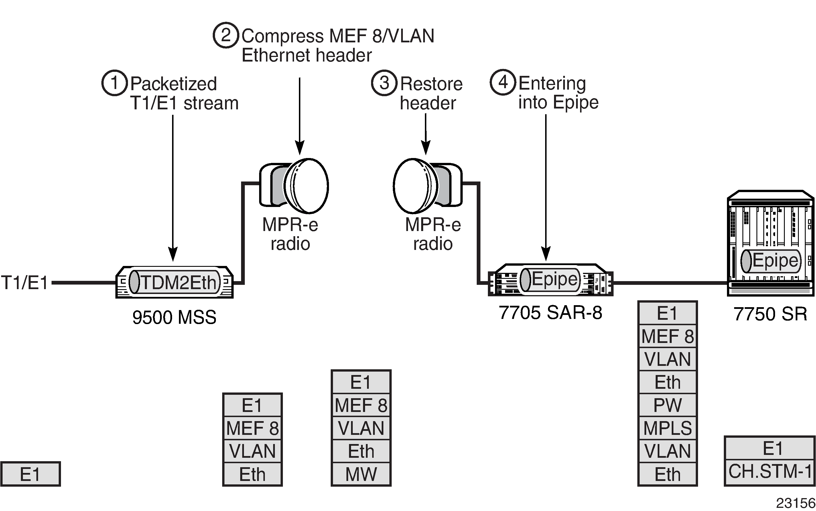
Apply Epipe SAP microwave link parameters for interworking with TDM2Ethernet as shown in the CLI syntax example below:
- CLI Syntax:
config>service>epipe epipe-id customer customer-id createsap sap-id createmwcompression source-mac destination-mac [rtp]
Configuring ATM Encapsulation Under Epipe Service (7705 SAR-M only)
The 7705 SAR-M can provide the transport of Ethernet traffic over an ATM network through the configuration of a SAP-to-SAP Ethernet PW. For example, as shown in Ethernet-to-ATM Interworking on the 7705 SAR-M, the 7705 SAR-M provides radio access of Ethernet traffic into an existing ATM network.
The SAP facing the eNodeB is configured as a null- or dot1q-encapsulated Ethernet SAP. The SAP facing the ATM network is ATM/IMA-encapsulated.
ATM/IMA is configured on E1 ports of the 7705 SAR-M. The uplink port must be in access mode in order to host the ATM/IMA SAP. The 7705 SAR-M supports IMA groups with 1 to 16 member links as well as ATM encapsulation on a single E1 port.
The following exceptions on ATM encapsulation under an Epipe service apply:
ATM SAPs are allowed on E1 and E1 IMA ports only
ETH-CFM OAM on an Ethernet SAP is not supported
ACL filtering is not supported
QinQ encapsulated Ethernet SAP interworking to an ATM SAP is not supported
ATM policing on an ATM SAP is not supported
-
the termination of ATM-encapsulated SAPs to IES for node management purposes. If the only transport uplink for a site is ATM, it is necessary to offer in-band management over the existing ATM network.
-
VC-mux routed PDU encapsulated SAPs for node management. The SAP must be attached to an IES service. No IP forwarding is supported on this management SAP.
For the application described in this section, an ATM-encapsulated SAP to IES is used for managing the 7705 SAR-M at the cell site. See IES for In-band Management for details.
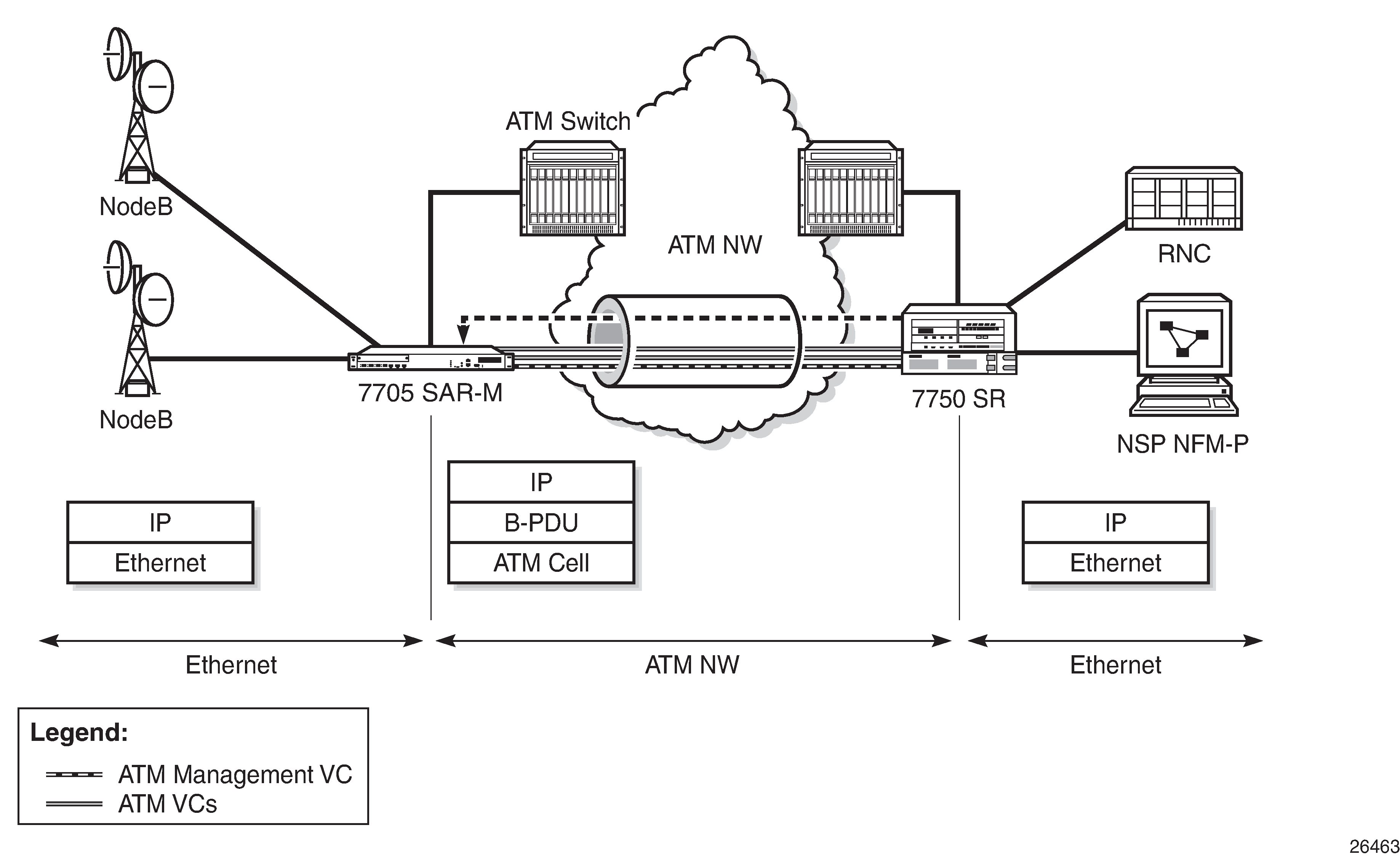
The following examples show the Epipe SAP-to-SAP configurations for Ethernet-to-ATM interworking. The first example shows the ATM SAP configuration (ATM VPI/VCI is 30/80), and the second example shows the IMA configuration (IMA bundle). In both examples, SAP 1/1/2:2 is the Ethernet SAP facing the eNodeB.
- Example:
epipe 105 customer 1 createsap 1/1/2:2 createexitsap 1/2/3.1:30/80 createexitno shutdownexit
- Example:
epipe 105 customer 1 createsap 1/1/2:2 createexitsap bundle-ima-1/2.1:20/200 createatmexitexitno shutdownexit
When ATM encapsulation under an Epipe service is used, the AAL-5 encapsulation type for the ATM SAP is ‟aal5mux-bridged-eth-nof*”, as shown in the following show>service>id service-id>sap sap-id detail screen.
-------------------------------------------------------------------------------
ATM SAP Configuration Information
-------------------------------------------------------------------------------
Ingress TD Profile : 1                        Egress TD Profile : 1
Ingress TD Ovr     : N/A                      Egress TD Ovr     : N/A
Alarm Cell Handling: Enabled
OAM Termination    : Disabled                 Periodic Loopback : Disabled
AAL-5 Encap        : aal5mux-bridged-eth-nof*
-------------------------------------------------------------------------------
Configuring Epipe Spoke SDP Bindings
SDPs—Unidirectional Tunnels shows an example of a distributed Epipe service configuration between two routers, identifying the service and customer IDs and the unidirectional SDPs required to communicate to the far-end routers. The spoke-sdp sdp-id:vc-id must match on both sides.
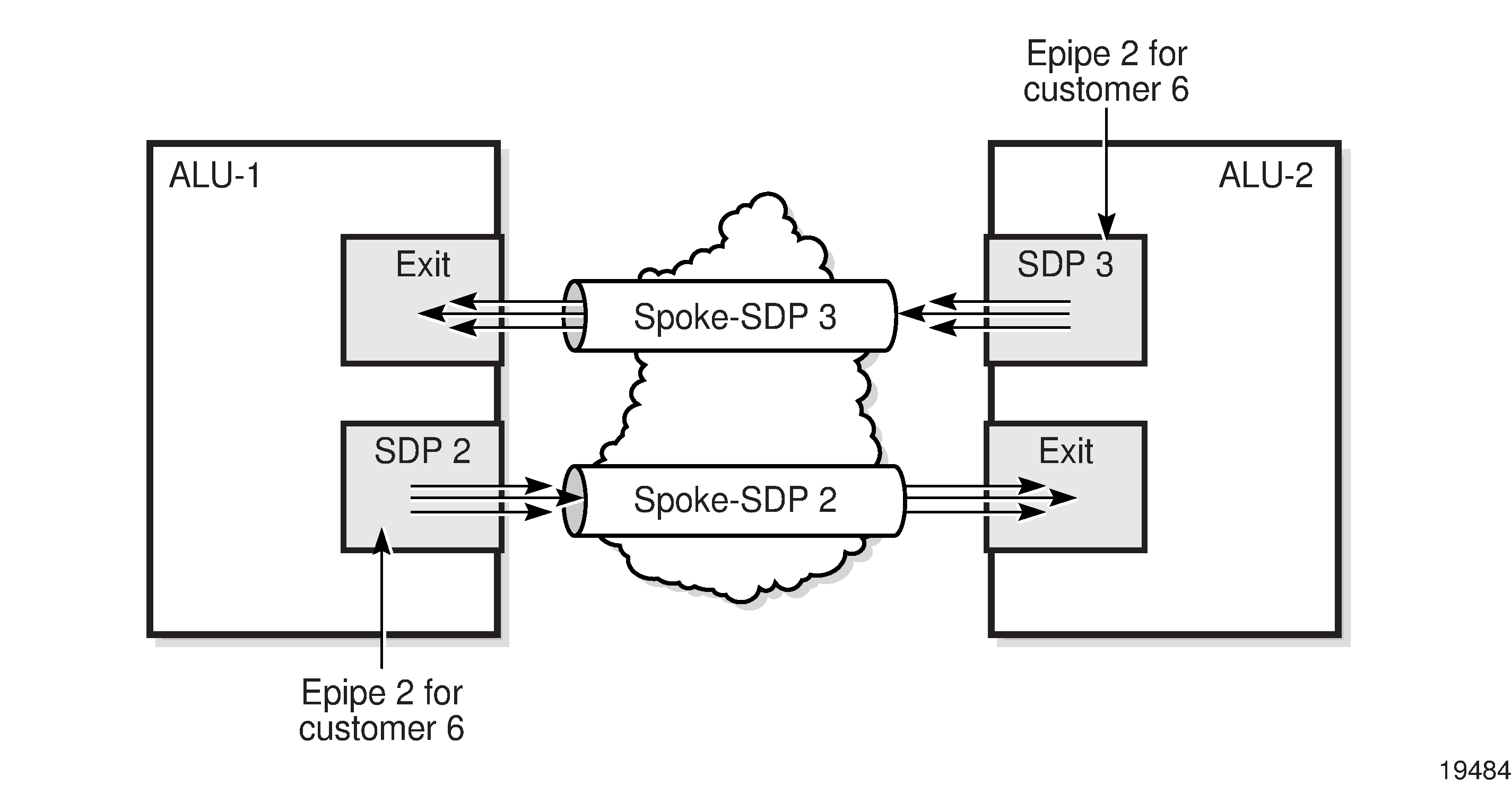
An SDP must exist before it can be used with a spoke SDP. For SDP configuration information, see Configuring SDPs.
For information about configuring ETH-CFM parameters on a spoke SDP, see ETH-CFM (802.1ag and Y.1731) Tasks.
Use the following CLI syntax to create a spoke SDP binding with an Epipe service.
- CLI Syntax:
config>service# epipe service-id [customer customer-id] [create] [vc-switching]spoke-sdp sdp-id:vc-id [vc-type {ether|vlan}] [create] vlan-vc-tag 0..4094egressvc-label egress-vc-labeleth-cfmingressvc-label ingress-vc-labelno shutdown
- Example:
ALU-1>config>service# epipe 5500config>service>epipe# spoke-sdp 2:123config>service>epipe>spoke-sdp# egressconfig>service>epipe>spoke-sdp>egress# vc-label 5500config>service>epipe>spoke-sdp>egress# exitconfig>service>epipe>spoke-sdp# ingressconfig>service>epipe>spoke-sdp>ingress# vc-label 6600config>service>epipe>spoke-sdp>ingress# exitconfig>service>epipe>spoke-sdp# no shutdownALU-2>config>service# epipe 5500config>service>epipe# spoke-sdp 2:123config>service>epipe>spoke-sdp# egressconfig>service>epipe>spoke-sdp>egress# vc-label 6600config>service>epipe>spoke-sdp>egress# exitconfig>service>epipe>spoke-sdp# ingressconfig>service>epipe>spoke-sdp>ingress# vc-label 5500config>service>epipe>spoke-sdp>ingress# exitconfig>service>epipe>spoke-sdp# no shutdown
The following example shows the configuration output for binding an Epipe service between ALU-1 and ALU-2. This example assumes the SAPs have already been configured (see Configuring Epipe SAP Parameters).
ALU-1>config>service# info
----------------------------------------------
...
        epipe 5500 customer 5 vpn 5500 create
            description "Distributed epipe service to east coast"
            sap 1/1/3:21 create
                ingress
                    filter ip 1
                    qos 555
                exit
                egress
                    qos 627
                exit
            exit
            spoke-sdp 2:123 create
                ingress
                    vc-label 6600
                exit
                egress
                    vc-label 5500
                exit
            exit
            no shutdown
        exit
...
----------------------------------------------
ALU-1>config>service#

ALU-2>config>service# info
----------------------------------------------
...
exit
        epipe 5500 customer 5 vpn 5500 create
            description "Distributed epipe service to west coast"
            sap 1/1/4:550 create
                ingress
                    qos 654
                exit
                egress
                    qos 432
                exit
            exit
            spoke-sdp 2:123 create
                ingress
                    vc-label 5500
                exit
                egress
                    vc-label 6600
                exit
            exit
            no shutdown
        exit
...
----------------------------------------------
Configuring a Security Zone Within an Epipe
To configure firewall security functionality, you must:
configure a firewall security profile and policy in the config>security context
in the config>security>profile context, specify the timeouts for the TCP/UDP/ICMP protocols and configure logging and application assurance parameters. This step is optional. If you do not configure the profile, a default profile is assigned.
in the config>security>policy context, configure a security policy and specify the match criteria and the action to be applied to a packet if a match is found
configure a firewall bypass policy in the config>security context and assign it to the Epipe, as shown in the following CLI syntax. This step is optional. If you do not configure a bypass policy, the protocol packets are firewalled based on the firewall security policies.
configure a security zone and apply the policy ID to the zone, as shown in the following CLI syntax
- CLI Syntax:
config>serviceepipe service-id [customer customer-id] [create]fw-bypass-policy {bypass-id | name}zone zone-id [create]abortbegincommitdescription description-stringinboundoutboundpolicy {policy-id | policy-name}sap sap-idshutdownspoke-sdp sdp-id:vc-id
The following example displays the security zone configuration output.
*A:Sar8 Dut-A>config>service>epipe# info
----------------------------------------------
            stp
                shutdown
            exit
            fw-bypass-policy 1
            sap 1/2/2 create
                no shutdown
            zone 1 create
                name "Epipe zone"
                description "Sample zone"
                sap ‟1/2/3”
                policy "4"
                inbound
                    limit
                    exit
                exit
                outbound
                    limit
                    exit
                exit
                commit
            exit
            no shutdown
----------------------------------------------
Creating an Fpipe Service
This section describes how to create an Fpipe service. Additional topics in this section include:
Use the following CLI syntax to create an Fpipe service.
- CLI Syntax:
config>service# fpipe service-id [customer customer-id] [create] [vpn vpn-id] [vc-type {fr-dlci}] [vc-switching]description description-stringservice-mtu octetsno shutdown
PE router 1 (A:ALU-41):
- Example:
A:ALU-41>config>service# fpipe 1 customer 1 createA:ALU-41>config>service>fpipe# description ‟fpipe test”A:ALU-41>config>service>fpipe# service-mtu 1400A:ALU-41>config>service>fpipe# no shutdownA:ALU-41>config>service>fpipe#
PE router 2 (A:ALU-42):
- Example:
A:ALU-42>config>service# fpipe 1 customer 1 createA:ALU-42>config>service>fpipe# description ‟fpipe test”A:ALU-42>config>service>fpipe# service-mtu 1400A:ALU-42>config>service>fpipe# no shutdownA:ALU-42>config>service>fpipe#
The following example shows the Fpipe service creation output.
PE Router 1 (ALU-41):
A:ALU-41>config>service# info
-------------------------------------
...
        fpipe 1 customer 1 create
            description "fpipe test"
            service-mtu 1400
            no shutdown
        exit
...
-------------------------------------
A:ALU-41>config>service#
PE Router 2 (ALU-42):
A:ALU-42>config>service# info
-------------------------------------
...
        fpipe 1 customer 1 create
            description "fpipe test"
            service-mtu 1400
            no shutdown
        exit
-------------------------------------
A:ALU-42>config>service#
Configuring Fpipe SAP Parameters
Use the following CLI syntax to configure Fpipe SAP parameters.
For ingress and egress configuration information, see Configuring Ingress and Egress SAP Parameters.
- CLI Syntax:
config>service# fpipe service-id [customer customer-id] [create] [vpn vpn-id] [vc-type {fr-dlci}] [vc-switching]sap sap-id [create]accounting-policy acct-policy-idcollect-statsdescription description-stringegressqos policy-idingressqos policy-id [shared-queuing]no shutdown
- Example:
A:ALU-41>config>service# fpipe 1A:ALU-41>config>service>fpipe# sap 1/2/1:16 createA:ALU-41>config>service>fpipe>sap# ingressA:ALU-41>config>service>fpipe>sap>ingress# qos 101A:ALU-41>config>service>fpipe>sap>ingress# exitA:ALU-41>config>service>fpipe>sap# egressA:ALU-41>config>service>fpipe>sap>egress# qos 1020A:ALU-41>config>service>fpipe>sap>egress# exitA:ALU-41>config>service>fpipe>sap# no shutdownA:ALU-41>config>service>fpipe>sap# exitA:ALU-41>config>service>fpipe#
The following example shows the Fpipe SAP configuration output for PE Router 1 (ALU-41).
A:ALU-41>config>service# info
-------------------------------------
...
        fpipe 1 customer 1 create
            description "fpipe test"
            service-mtu 1400
            sap 1/2/1:16 create
               ingress
                   qos 101
               exit
               egress
                   qos 1020
               exit
            exit
            no shutdown
        exit
...
-------------------------------------
To configure a basic local Fpipe service (SAP-to-SAP), enter the sap sap-id command twice with different port IDs in the same service configuration.
The following example shows an FR SAP-to-SAP configuration:
A:ALU-41>config>service# info
-------------------------------------
...
        fpipe 1 customer 1 create
            description "FR sap2sap"
            service-mtu 1400
            sap 1/2/1:16
            sap 1/3/1:20
            no shutdown
        exit
...
-------------------------------------
Configuring Fpipe SDP Bindings
Use the following CLI syntax to create a spoke SDP binding with an Fpipe service (for distributed service). For SDP configuration information, see Configuring SDPs.
- CLI Syntax:
config>service# fpipe service-id [customer customer-id] [create] [vpn vpn-id] [vc-type {fr-dlci}] [vc-switching]spoke-sdp sdp-id:vc-id [create]egressvc-label egress-vc-labelingressvc-label ingress-vc-labelno shutdown
- Example:
A:ALU-41>config>service# fpipe 1A:ALU-41>config>service>fpipe# spoke-sdp 1:1 createA:ALU-41>config>service>fpipe>spoke-sdp# no shutdownA:ALU-41>config>service>fpipe>spoke-sdp# exit
The following example shows the Fpipe spoke SDP configuration output for PE Router 1 (ALU-41).
A:ALU-41>config>service# info
-------------------------------------
...
        fpipe 1 customer 1 create
            description "fpipe test"
            service-mtu 1400
            sap 1/2/1:16 create
               ingress
                   qos 101
               exit
               egress
                   qos 1020
               exit
            exit
            spoke-sdp 1:1 create
            exit
            no shutdown
        exit
...
-------------------------------------
A:ALU-41>config>service#
Creating an Hpipe Service
This section describes how to create an Hpipe service. Additional topics in this section include:
Use the following CLI syntax to create an Hpipe service.
- CLI Syntax:
config>service# hpipe service-id [customer customer-id] [create] [vpn vpn-id] [vc-type {hdlc}] [vc-switching]description description-stringservice-mtu octetsno shutdown
PE router 1 (ALU-41):
- Example:
A:ALU-41>config>service# hpipe 4 customer 1 createA:ALU-41>config>service>hpipe# description ‟hpipe test”A:ALU-41>config>service>hpipe# service-mtu 1400A:ALU-41>config>service>hpipe# no shutdownA:ALU-41>config>service>hpipe#
PE router 2 (ALU-42):
- Example:
A:ALU-42>config>service# hpipe 4 customer 1 createA:ALU-42>config>service>hpipe# description ‟hpipe test”A:ALU-42>config>service>hpipe# service-mtu 1400A:ALU-42>config>service>hpipe# no shutdownA:ALU-42>config>service>hpipe#
The following example shows the Hpipe service creation output.
PE Router 1 (ALU-41):
A:ALU-41>config>service# info
-------------------------------------
...
        hpipe 4 customer 1 create
            description "hpipe test"
            service-mtu 1400
            no shutdown
        exit
...
-------------------------------------
A:ALU-41>config>service#
PE Router 2 (ALU-42):
A:ALU-42>config>service# info
-------------------------------------
...
        hpipe 4 customer 1 create
            description "hpipe test"
            service-mtu 1400
            no shutdown
        exit
Configuring Hpipe SAP Parameters
Use the following CLI syntax to configure Hpipe SAP parameters. For ingress and egress configuration information, see Configuring Ingress and Egress SAP Parameters.
- CLI Syntax:
config>service# hpipe service-id [customer customer-id] [create] [vpn vpn-id] [vc-type {hdlc}] [vc-switching]sap sap-id [create]accounting-policy acct-policy-idcollect-statsdescription description-stringegressqos policy-idingressqos policy-id [shared queuing]no shutdown
- Example:
A:ALU-41>config>service# hpipe 4A:ALU-41>config>service>hpipe# sap 1/4/1.20 createA:ALU-41>config>service>hpipe>sap# ingressA:ALU-41>config>service>hpipe>sap>ingress# qos 102A:ALU-41>config>service>hpipe>sap>ingress# exitA:ALU-41>config>service>hpipe>sap# egressA:ALU-41>config>service>hpipe>sap>egress# qos 103A:ALU-41>config>service>hpipe>sap>egress# exitA:ALU-41>config>service>hpipe>sap# no shutdownA:ALU-41>config>service>hpipe>sap# exitA:ALU-41>config>service>hpipe#
The following example shows the Hpipe SAP configuration output for PE Router 1 (ALU-41).
A:ALU-41>config>service# info
-------------------------------------
...
        hpipe 4 customer 1 create
            description "hpipe test"
            service-mtu 1400
            sap 1/4/1.20 create
               ingress
                   qos 102
               exit
               egress
                   qos 103
               exit
            exit
            no shutdown
        exit
...
-------------------------------------
To configure a basic local Hpipe service (SAP-to-SAP), enter the sap sap-id command twice with different port IDs in the same service configuration.
The following example shows an HDLC SAP-to-SAP configuration:
A:ALU-41>config>service# info
-------------------------------------
...
        hpipe 4 customer 1 create
            description "HDLC sap2sap"
            service-mtu 1514
            sap 1/4/1.20
            sap 1/5/1.10
            no shutdown
        exit
...
-------------------------------------
Configuring Hpipe SDP Bindings
Use the following CLI syntax to create a spoke SDP binding with an Hpipe service (for distributed service). For SDP configuration information, see Configuring SDPs.
- CLI Syntax:
config>service# hpipe service-id [customer customer-id] [create] [vpn vpn-id] [vc-type {hdlc}] [vc-switching]spoke-sdp sdp-id:vc-id [create]egressvc-label egress-vc-labelingressvc-label ingress-vc-labelno shutdown
- Example:
A:ALU-41>config>service# hpipe 4A:ALU-41>config>service>hpipe# spoke-sdp 1:4 createA:ALU-41>config>service>hpipe>spoke-sdp# no shutdownA:ALU-41>config>service>hpipe>spoke-sdp# exit
The following example shows the Hpipe spoke SDP configuration output for PE Router 1 (ALU-41).
A:ALU-41>config>service# info
-------------------------------------
...
        hpipe 4 customer 1 create
            description "hpipe test"
            service-mtu 1400
            sap 1/4/1.20 create
               ingress
                   qos 102
               exit
               egress
                   qos 103
               exit
            exit
            spoke-sdp 1:4 create
            exit
            no shutdown
        exit
...
-------------------------------------
A:ALU-41>config>service#
Creating an Ipipe Service
This section describes how to create an Ipipe service. Additional topics in this section include:
Use the following CLI syntax to create an Ipipe service.
- CLI Syntax:
config>service# ipipe service-id [customer customer-id] [vpn vpn-id] [vc-switching]description description-stringno shutdown
The following example shows an Ipipe configuration:
A:ALU-1>config>service# info
-------------------------------------------
...
        ipipe 202 customer 1 create
            description "eth_ipipe"
            no shutdown
        exit
-------------------------------------------
A:ALU-1>config>service#
Configuring Ipipe SAP Parameters
The following example shows an Ipipe SAP configuration:
A:ALU-48>config>service# info
----------------------------------------------
...
        ipipe 202 customer 1 create
            sap 1/1/2:444 create
                description "eth_ipipe"
                ce-address 172.16.0.0
            exit
             spoke-sdp 16:516 create
                ce-address 172.16.0.1
            exit
            no shutdown
        exit
...
----------------------------------------------
The following shows a PPP to Ethernet local Ipipe example:
- Example:
config>service# ipipe 206 customer 1 createconfig>service>ipipe$ sap 1/1/2:447 createconfig>service>ipipe>sap$ description "eth_ppp_ipipe"config>service>ipipe>sap$ ce-address 172.16.0.0config>service>ipipe>sap$ no shutdownconfig>service>ipipe>sap$ exitconfig>service>ipipe# spoke-sdp 15:516 createconfig>service>ipipe>sap>spoke-sdp$ ce-address 172.16.0.1config>service>ipipe>sap-spoke-sdp$ exitconfig>service>ipipe>$ exitconfig>service>ipipe# no shutdownconfig>service>ipipe# exitconfig>service#
The following shows the output:
A:ALU-48>config>service# info
----------------------------------------------
ipipe 206 customer 1 create
            sap 1/1/2:447 create
                description "eth_ppp_ipipe"
                ce-address 172.16.0.0
            exit
            spoke-sdp 15:516 create
                ce-address 172.16.0.1
             exit
            exit
            no shutdown
        exit
exit
----------------------------------------------
The configuration of a Cisco HDLC SAP on an Ipipe is similar to the above example, except that the sap-id has the form slot/mda/port.channel-group (1/2/2.1).
Configuring Ipipe SDP Bindings
The following shows an Ipipe SDP configuration example:
A:ALU-48>config>service# info
----------------------------------------------
...
        sdp 16 mpls create
            far-end 10.4.4.4
            ldp
            path-mtu 1600
            keep-alive
                shutdown
            exit
            no shutdown
        exit
...
        ipipe 207 customer 1 create
            shutdown
            sap 1/1/2:449 create
                description "Remote_Ipipe"
                ce-address 172.16.0.10
            exit
            spoke-sdp 16:516 create
                ce-address 172.16.0.11
            exit
Configuring PW Switching
The vc-switching parameter defines a VLL service as a PW switching point, also called an S-PE. This is the point where a VLL service switches from one PW type to another. The vc-switching parameter must be specified when the VLL service is created.
Once a VLL service is configured as an S-PE, you cannot add a SAP to the configuration. The following example shows the error message generated by the CLI if you attempt to create a SAP on a VLL PW switching service.
- Example:
*A:ALU>config>service>epipe 2 customer 1 createvc-switching*A:ALU>config>service>epipe$ sap 1/5/1 createMINOR: SVCMGR #1311 SAP is not allowed under PW switching service*A:ALU>config>service>epipe$
Use the following CLI syntax to configure pseudowire switching VLL services.
- CLI Syntax:
config>service# apipe service-id [customer customer-id] [create] [vpn vpn-id] [vc-type {atm-vcc|atm-vpc|atm-cell}] [vc-switching]description description-stringspoke-sdp sdp-id:vc-idno shutdownconfig>service# cpipe service-id [customer customer-id] [create] [vpn vpn-id] [vc-type {satop-e1 | satop-t1 | satop-e3 | satop-t3 | cesopsn | cesopsn-cas}] [vc-switching]description description-stringservice-mtu octetsno shutdownconfig>service# epipe service-id [customer customer-id] [create] [vpn vpn-id] [vc-switching]description description-stringspoke-sdp sdp-id:vc-idno shutdownconfig>service# fpipe service-id [customer customer-id] [create] [vpn vpn-id] [vc-type {fr-dlci}] [vc-switching]description description-stringspoke-sdp sdp-id:vc-idno shutdownconfig>service# hpipe service-id [customer customer-id] [create] [vpn vpn-id] [vc-type {hdlc}] [vc-switching]description description-stringspoke-sdp sdp-id:vc-idno shutdownconfig>service# ipipe service-id [customer customer-id] [vpn vpn-id] [vc-switching]description description-stringspoke-sdp sdp-id:vc-idno shutdown
The following shows an example of the command usage to configure a VLL service as a PW switching service:
- Example:
ALU-1>config>service# apipe 5 customer 1 vpn 1 vc-switching createconfig>service>apipe$ description ‟Default apipe description for service id 100”config>service>apipe# spoke-sdp 3:1 createconfig>service>apipe>spoke-sdp# exitconfig>service>apipe# spoke-sdp 6:200 createconfig>service>apipe>spoke-sdp# exitconfig>service>apipe# no shutdown
The following example shows configurations for each service:
*A:ALA-48>config>service# info
----------------------------------------------
apipe 100 customer 1 vpn 1 vc-switching create
description "Default apipe description for service id 100"
spoke-sdp 3:1 create
exit
spoke-sdp 6:200 create
exit
no shutdown
exit
...
cpipe 107 customer 1 vpn 107 vc-switching vc-type satop-e1 create
description "Default cpipe description for service id 107"
spoke-sdp 3:7 create
exit
spoke-sdp 6:207 create
exit
no shutdown
exit
...
epipe 108 customer 1 vpn 108 vc-switching create
description "Default epipe description for service id 108"
spoke-sdp 3:8 create
exit
spoke-sdp 6:208 create
exit
no shutdown
exit
...
fpipe 109 customer 1 vpn 75 vc-switching create
description "Default fpipe description for service id 109"
spoke-sdp 3:9 create
exit
spoke-sdp 6:209 create
exit
no shutdown
exit
...
hpipe 110 customer 1 vpn 76 vc-switching create
description "Default hpipe description for service id 110"
spoke-sdp 3:10 create
exit
spoke-sdp 6:210 create
exit
no shutdown
exit
...
ipipe 111 customer 1 vpn 77 vc-switching create
description "Default ipipe description for service id 111"
spoke-sdp 3:11 create
exit
spoke-sdp 6:211 create
exit
no shutdown
exit
...
----------------------------------------------
Configuring Ingress and Egress SAP Parameters
By default, QoS policy ID 1 is applied to ingress and egress service SAPs. Existing QoS policies can be associated with service SAPs on ingress and egress ports.
Ingress and egress QoS SAP parameters can be applied to distributed and local Epipe, Fpipe, Hpipe, and Ipipe service SAPs, and to local Apipe and Cpipe service SAPs.
Ingress and egress QoS parameters can also be applied to SAP aggregation groups for ATM VCC VLL services. QoS parameters cannot be applied to SAPs that are members of the aggregation group.
By default, there are no IP filters associated with interfaces or services. IP filter policies can be applied to ingress Epipe and Ipipe service SAPs.
- Example:
ALU-1>config>service# epipe 5500config>service>epipe# sap 1/1/3:21config>service>epipe>sap# ingressconfig>service>epipe>sap>ingress# filter ip 1config>service>epipe>sap>ingress# qos 555config>service>epipe>sap>ingress# exitconfig>service>epipe>sap# egressconfig>service>epipe>sap>egress# qos 627config>service>epipe>sap>egress# exitconfig>service>epipe>sap#
The following example shows the Epipe SAP ingress and egress configuration output.
ALU-1>config>service#
----------------------------------------------
        epipe 5500 customer 5 vpn 5500 create
            description "Distributed epipe service to east coast"
            sap 1/1/3:21 create
                ingress
                    filter ip 1
                    qos 555
                exit
                egress
                    qos 627
                exit
            exit
            spoke-sdp 2:123 create
                ingress
                    vc-label 6600
                exit
                egress
                    vc-label 5500
                exit
            exit
            no shutdown
        exit
----------------------------------------------
Using the Control Word
The control word is mandatory for Cpipe SAToP and CESoPSN configurations, Epipe MEF 8 configurations, and Fpipe one-to-one mapping configurations.
The control word is optional for Apipe, Epipe (non-MEF 8), Hpipe, and Ipipe services, but must be enabled for Hpipe pseudowire services when transporting packets that are less than 64 bytes. If the control word is enabled for Epipe or Ipipe services, it will be set to all zeros and ignored on egress.
When the control word is enabled, the Admin Control Word is set to Preferred. Both sides of the VLL must be configured with a matching control word, either both enabled or both disabled, for the pipe to be up.
The control word state will be set to True or False depending on what is configured, either enabled (True) or disabled (False).
- Example:
config>service# cpipe 2100 customer 1config>service>cpipe$ description ”Default cpipe description for service id 2100”config>service>cpipe$ sap 1/2/7.1:4 createconfig>service>cpipe>sap$ description ‟Default sap description for service id 2100”config>service>cpipe>sap$ exitconfig>service>cpipe# spoke-sdp 1:2001 createconfig>service>cpipe>spoke-sdp$ control-wordconfig>service>cpipe>spoke-sdp$ exitconfig>service>cpipe# no shutdown
The following example shows the control word configuration output for a Cpipe service.
*A:ALU-Dut-B>config>service>cpipe# info
----------------------------------------------
            description "Default cpipe description for service id 2100"
            sap 1/2/7.1:4 create
                description "Default sap description for service id 2100"
            exit
            spoke-sdp 1:2001 create
                control-word
            exit
            no shutdown
----------------------------------------------
*A:ALU-Dut-B>config>service>cpipe#
The control word cannot be disabled on Cpipe, Epipe MEF 8, or Fpipe services. To disable the control word option on Apipe, Epipe (non-MEF 8), Hpipe, or Ipipe services, use the no control-word command.
- Example:
config>service>apipe# spoke-sdp 1:2001 no control-wordconfig>service>apipe>spoke-sdp$ exit
Configuring PW Redundancy
This section describes configuring PW redundancy. Additional topics in this section include:
For PW redundancy, create an explicit endpoint and then assign a primary spoke SDP and up to three secondary spoke SDPs, or up to four secondary spoke SDPs with no primary spoke SDP, to that endpoint.
- CLI Syntax:
config>service# cpipe service-id [customer customer-id] [create]endpoint endpoint-name [create]spoke-sdp sdp-id:vc-id endpoint endpoint-name [create]precedence precedence-valueno shutdown
- Example:
config>service# cpipe 2100config>service>cpipe$ endpoint ‟Endpoint_Y” createconfig>service>cpipe$ spoke-sdp 1:100 endpoint‟Endpoint_Y” createconfig>service>cpipe>spoke-sdp$ precedence primaryconfig>service>cpipe$ spoke-sdp 2:200 endpoint‟Endpoint_Y” createconfig>service>cpipe>spoke-sdp$ precedence 1no shutdown
The following example shows the PW redundancy configuration output for a Cpipe service.
*A:7705:Dut-C>config>service>cpipe# info
----------------------------------------------
            endpoint "Endpoint_Y" create
            exit
            spoke-sdp 1:100 endpoint "Endpoint_Y" create
                precedence primary
            exit
            spoke-sdp 2:200 endpoint "Endpoint_Y" create
                precedence 1
            exit
----------------------------------------------------
*A:7705:Dut-C>config>service>cpipe#
Configuring PW Redundancy—Standby Signaling
For standby signaling, create an endpoint as shown in the preceding section, but specify an SDP as the standby signaling master and the far-end endpoints as standby signaling slaves.
In the following example, precedence primary indicates that the spoke SDP is the active SDP and precedence 1 indicates that the spoke SDP is the standby SDP.
To create a standby signaling master:
- CLI Syntax:
config>service# cpipe service-id [customer customer-id] [create]endpoint endpoint-name [create]standby-signaling-masterexitspoke-sdp sdp-id:vc-id endpoint endpoint-name [create]precedence precedence-valueno shutdown
- Example:
config>service cpipe 555config>service>cpipe# endpoint ‟stdbyMaster” createconfig>service>cpipe>endpoint# standby-signaling-masterconfig>service>cpipe>endpoint# exitconfig>service>cpipe# spoke-sdp 5:555 endpoint‟stdbyMaster” createconfig>service>cpipe>spoke-sdp$ precedence primaryexitconfig>service>cpipe# spoke-sdp 131:555 endpoint‟stdbyMaster” createconfig>service>cpipe>spoke-sdp$ precedence 1exit
To create the far-end endpoints as standby signaling slaves:
- CLI Syntax:
config>service# cpipe service-id [customer customer-id] [create]endpoint endpoint-name [create]standby-signaling-slaveexitspoke-sdp sdp-id:vc-id endpoint endpoint-name [create]precedence precedence-valueno shutdown
- Example:
config>service cpipe 555config>service>cpipe# endpoint ‟FarendA” createconfig>service>cpipe>endpoint# standby-signaling-slaveconfig>service>cpipe>endpoint# exitconfig>service>cpipe# spoke-sdp 130:555 endpoint‟FarendA” createconfig>service>cpipe>spoke-sdp$ precedence primaryexit
- Example:
config>service cpipe 555config>service>cpipe# endpoint ‟FarendB” createconfig>service>cpipe>endpoint# standby-signaling-slaveconfig>service>cpipe>endpoint# exitconfig>service>cpipe# spoke-sdp 130:555 endpoint‟FarendB” createconfig>service>cpipe>spoke-sdp$ precedence primaryexit
Configuring PW Redundancy—ICB
Inter-Chassis Backup (ICB) spoke SDPs are supported for use with Cpipe services in an MC-APS configuration or MC-LCR configuration and with Epipe services in an MC-LAG configuration. ICB improves switch times, provides additional protection in case of network failures, and reduces packet loss when an active endpoint is switched from a failed MC-APS, MC-LCR, or MC-LAG node to a protection node.
To configure ICB, create explicit endpoints on the access and network side on the working node and then assign a primary spoke SDP on the reverse side of the protection node.
- CLI Syntax:
config>service# cpipe service-id [customer customer-id] [create]description description-stringendpoint endpoint-name [create]service-mtu octetsstandby-signaling-masterexitsap sap-id [create]spoke-sdp sdp-id:vc-id endpoint endpoint-name [icb] [create]precedence precedence-valueno shutdown
The example below shows how to configure ICB on the working node in an MC-APS scenario:
- Example:
config>service cpipe 555config>service>cpipe# description ‟Cpipe for service id 1”config>service>cpipe# service-mtu 1000config>service>cpipe# endpoint ‟X” createconfig>service>cpipe>endpoint# exitconfig>service>cpipe# endpoint ‟Y” createconfig>service>cpipe>endpoint# exitconfig>service>cpipe# sap aps-1.1.1.1.1 endpoint ‟X” createconfig>service>cpipe>sap# description ‟SAP for service id 1”config>service>cpipe>sap# exitconfig>service>cpipe# spoke-sdp 2003:1 endpoint‟Y” createconfig>service>cpipe>spoke-sdp# exitconfig>service>cpipe# spoke-sdp 2004:1001 endpoint ‟X” icb createconfig>service>cpipe>spoke-sdp# exitconfig>service>cpipe# spoke-sdp 2004:1001 endpoint ‟Y” icb createconfig>service>cpipe>spoke-sdp# exitconfig>service>cpipe# no shutdownexit
The example below shows how to configure ICB on the protection node in an MC-APS scenario:
- Example:
config>service cpipe 1 vc-type cesopsn createconfig>service>cpipe# service-mtu 1000config>service>cpipe# endpoint ‟X” createconfig>service>cpipe>endpoint# exitconfig>service>cpipe# endpoint ‟Y” createconfig>service>cpipe>endpoint# exitconfig>service>cpipe# sap aps-1.1.1.1.1 endpoint ‟X” createconfig>service>cpipe>sap# description ‟SAP description for service id 1”config>service>cpipe>sap# exitconfig>service>cpipe# spoke-sdp 4003:1 endpoint‟Y” createconfig>service>cpipe>spoke-sdp# exitconfig>service>cpipe# spoke-sdp 4002:1001 endpoint ‟Y” icb createconfig>service>cpipe>spoke-sdp# exitconfig>service>cpipe# spoke-sdp 4002:2001 endpoint ‟X” icb createconfig>service>cpipe>spoke-sdp# exitconfig>service>cpipe# no shutdownexit
The CLI output below shows an example of ICB configured on the working node in an MC-LCR scenario:
 cpipe 1 customer 1 vc-type cesopsn create
            description "Default Cpipe description for service id 1"
            service-mtu 1000
            endpoint "X" create
            exit
            endpoint "Y" create
            exit
            sap lcr-1/1.1 endpoint "X" create
                description "Default sap description for service id 1"
                no shutdown
            exit
            spoke-sdp 6003:1 endpoint "Y" create
                no shutdown
            exit
            spoke-sdp 6001:1001 endpoint "X" icb create
                no shutdown
            exit
            spoke-sdp 6001:2001 endpoint "Y" icb create
               no shutdown
            exit
            no shutdown
        exit
The CLI output below shows an example of ICB configured on the protection node in an MC-LCR scenario:
 cpipe 1 customer 1 vc-type cesopsn create
            description "Default Cpipe description for service id 1"
            service-mtu 1000
            endpoint "X" create
            exit
            endpoint "Y" create
            exit
            sap lcr-1/1.1 endpoint "X" create
                description "Default sap description for service id 1"
                no shutdown
            exit
            spoke-sdp 1003:1 endpoint "Y" create
                no shutdown
            exit
            spoke-sdp 1006:1001 endpoint "Y" icb create
                no shutdown
            exit
            spoke-sdp 1006:2001 endpoint "X" icb create
                no shutdown
            exit
            no shutdown
        exit
Service Management Tasks
The service management tasks are similar for Apipe, Cpipe, Epipe, and Ipipe services. This section discusses the following service management tasks:
Modifying Service Parameters
Use the show service service-using command to display a list of configured VLL services.
To modify a VLL service:
Access the specific account by specifying the service ID.
Enter the service parameter to modify and then enter the new information.
PE router 1 (A:ALU-41):
- Example:
A:ALU-41>config>service# apipe 5A:ALU-41>config>service>apipe# sap 1/1/1.1:0/32 createA:ALU-41>config>service>apipe>sap# accounting-policy 2A:ALU-41>config>service>apipe>sap# exitA:ALU-41>config>service>apipe# spoke-sdp 1:4A:ALU-41>config>service>apipe>spoke-sdp# egressA:ALU-41>config>service>apipe>spoke-sdp>egress# vc-label 2048A:ALU-41>config>service>apipe>spoke-sdp>egress# exitA:ALU-41>config>service>apipe>spoke-sdp# ingressA:ALU-41>config>service>apipe>spoke-sdp>ingress# vc-label 18431A:ALU-41>config>service>apipe>spoke-sdp>ingress# exitA:ALU-41>config>service>apipe>spoke-sdp# exitA:ALU-41>config>service>apipe#
PE router 2 (A:ALU-42):
- Example:
A:ALU-42>config>service# apipe 5A:ALU-42>config>service>apipe# sap 2/2/2.1:0/32 createA:ALU-42>config>service>apipe>sap# accounting-policy 2A:ALU-42>config>service>apipe>sap# exitA:ALU-42>config>service>apipe# spoke-sdp 1:4A:ALU-42>config>service>apipe>spoke-sdp# egressA:ALU-42>config>service>apipe>spoke-sdp>egress# vc-label 18431A:ALU-42>config>service>apipe>spoke-sdp>egress# exitA:ALU-41>config>service>apipe>spoke-sdp# ingressA:ALU-41>config>service>apipe>spoke-sdp>ingress# vc-label 2043A:ALU-41>config>service>apipe>spoke-sdp>ingress# exitA:ALU-42>config>service>apipe>spoke-sdp# exitA:ALU-42>config>service>apipe#
The following example shows the configuration output when adding an accounting-policy to an existing SAP and modifying the spoke SDP parameters on an existing Apipe service for PE Router 1 (ALU-41) and PE Router 2 (ALU-42).
Use a similar syntax to modify Cpipe, Epipe, and Ipipe services.
A:ALU-41>config>service# info
-------------------------------------
...
        apipe 5 customer 1 create
            description "apipe test"
            service-mtu 1400
            sap 1/1/1.1:0/32 create
               accounting-policy 2
               ingress
                   qos 102
               exit
               egress
                   qos 103
               exit
            exit
            spoke-sdp 1:4 create
               egress
                   vc-label 2048
               ingress
                   vc-label 18431
          exit
            no shutdown
        exit
...
-------------------------------------
A:ALU-41>config>service#


A:ALU-42>config>service# info
-------------------------------------
...
        apipe 5 customer 1 create
            description "apipe test"
            service-mtu 1400
            sap 2/2/2.1:0/32 create
               accounting-policy 2
               ingress
                   qos 102
               exit
               egress
                   qos 103
               exit
            exit
            spoke-sdp 1:4 create
               egress
                   vc-label 18431
               ingress
                   vc-label 2048
          exit
            no shutdown
        exit
...
-------------------------------------
A:ALU-42>config>service#
Disabling a Service
A service can be shut down without deleting the service parameters.
Use the shutdown command to shut down a VLL service. The following CLI syntax shows the command to shut down an Apipe service. Use a similar syntax to shut down Cpipe, Epipe, Fpipe, Hpipe, and Ipipe services.
- CLI Syntax:
config>service#apipe service-idshutdown
PE router 1 (A:ALU-41):
- Example:
A:ALU-41>config>service# apipe 5A:ALU-41>config>service>apipe# shutdownA:ALU-41>config>service>apipe# exit
PE router 2 (A:ALU-42):
- Example:
A:ALU-42>config>service# apipe 5A:ALU-42>config>service>apipe# shutdownA:ALU-42>config>service>apipe# exit
The following example shows the configuration output for deleting an Apipe service on PE Router 1 (ALU-41) and PE Router 2 (ALU-42).
A:ALU-41>config>service# info
-------------------------------------
...
        apipe 5 customer 1 create
            shutdown
            description "apipe test"
            service-mtu 1400
            sap 1/1/1.1:0/32 create
               accounting-policy 2
               ingress
                   qos 102
               exit
               egress
                   qos 103
               exit
            exit
            spoke-sdp 1:4 create
               egress
                   vc-label 16
            exit
            no shutdown
        exit
...
-------------------------------------
A:ALU-41>config>service#

A:ALU-42>config>service# info
-------------------------------------
...
        apipe 5 customer 1 create
            shutdown
            description "apipe test"
            service-mtu 1400
            sap 2/2/2.1:0/32 create
               accounting-policy 2
               ingress
                   qos 102
               exit
               egress
                   qos 103
               exit
            exit
            spoke-sdp 1:4 create
               egress
                   vc-label 16
            exit
        exit
...
-------------------------------------
A:ALU-42>config>service#
Re-enabling a Service
Use the no shutdown command to re-enable a previously disabled VLL service. The following CLI syntax shows the command to re-enable an Apipe service. Use a similar syntax to re-enable Cpipe, Epipe, Fpipe, Hpipe, and Ipipe services.
- CLI Syntax:
config>service#apipe service-idno shutdown
PE router 1 (A:ALU-41):
- Example:
A:ALU-41>config>service# apipe 5A:ALU-41>config>service>apipe# no shutdownA:ALU-41>config>service>apipe# exit
PE router 2 (A:ALU-42):
- Example:
A:ALU-42>config>service# apipe 5A:ALU-42>config>service>apipe# no shutdownA:ALU-42>config>service>apipe# exit
Deleting a Service
Use the shutdown command to delete a VLL service. The SAP, and any associated protocols and spoke SDPs, must be deleted from the VLL service before the VLL service can be deleted.
Perform the following steps to delete a service:
Shut down the SAP and SDP.
Delete the SAP and SDP.
Shut down the service.
Use the following syntax to delete Apipe services. Use a similar syntax to delete Cpipe, Epipe, Fpipe, Hpipe, and Ipipe services.
- CLI Syntax:
config>service#apipe service-idsap sap-idshutdownexitno sap sap-idspoke-sdp [sdp-id:vc-id]shutdownexitno spoke-sdp [sdp-id:vc-id]shutdownexitno apipe service-id
- Example:
A:ALU-41>config>service# apipe 5A:ALU-41>config>service>apipe# sap 1/1/1.1:0/32A:ALU-41>config>service>apipe>sap# shutdownA:ALU-41>config>service>apipe>sap# exitA:ALU-41>config>service>apipe# no sap 1/1/1.1:0/32A:ALU-41>config>service>apipe# spoke-sdp 1:4A:ALU-41>config>service>apipe>spoke-sdp# shutdownA:ALU-41>config>service>apipe>spoke-sdp# exitA:ALU-41>config>service>apipe# no spoke-sdp 1:4A:ALU-41>config>service>apipe# shutdownA:ALU-41>config>service>apipe# exitA:ALU-41>config>service# no apipe 5
VLL Services Command Reference
Command Hierarchies
VLL Services Configuration Commands
Apipe Service Configuration Commands
config
    - service
        - apipe service-id [customer customer-id] [create] [vpn vpn-id] [vc-type {atm-vcc | atm-vpc | atm-cell}] [vc-switching]
        - no apipe service-id
            - description description-string
            - no description
            - [no] endpoint endpoint-name
                - description description-string
                - no description
                - revert-time [revert-time | infinite]
                - no revert-time
                - [no] standby-signaling-master
            - sap sap-id [create]
            - no sap sap-id
                - accounting-policy acct-policy-id
                - no accounting-policy
                - atm
                    - egress
                        - traffic-desc traffic-desc-profile-id
                        - no traffic-desc
                    - ingress
                        - traffic-desc traffic-desc-profile-id
                        - no traffic-desc
                    - oam
                        - [no] alarm-cells
                - [no] collect-stats
                - description description-string
                - no description
                - egress
                    - qos policy-id
                    - no qos
                - ingress
                    - qos policy-id
                    - no qos
                - [no] shutdown
            - service-mtu octets
            - no service-mtu
            - service-name service-name
            - no service-name
            - [no] shutdown
            - spoke-sdp sdp-id:vc-id [create] [no-endpoint] (see Note)
            - spoke-sdp sdp-id:vc-id [create] endpoint endpoint-name
            - no spoke-sdp sdp-id:vc-id
                - cell-concatenation
                    - [no] clp-change
                    - max-cells cell-count
                    - no max-cells [cell-count]
                    - max-delay delay-time
                    - no max-delay [delay-time]
                - [no] control-word
                - [no] egress
                    - vc-label egress-vc-label
                    - no vc-label [egress-vc-label]
                - [no] ingress
                    - vc-label ingress-vc-label
                    - no vc-label [ingress-vc-label]
                - precedence [precedence-value | primary]
                - no precedence
                - [no] shutdown
Apipe Service with SAP Aggregation Configuration Commands
config
    - service
        - apipe service-id [customer customer-id] [vpn vpn-id] [vc-type {atm-vcc | atm-vpc}] [vc-switching] [create]
        - no apipe service-id
            - description description-string
            - no description
            - [no] endpoint endpoint-name
                - description description-string
                - no description
                - revert-time [revert-time | infinite]
                - no revert-time
                - [no] standby-signaling-master
            - sap-aggregation-group group-id [create]
            - no sap-aggregation-group group-id
                - accounting-policy acct-policy-id
                - no accounting-policy
                - [no] collect-stats
                - description description-string
                - no description
                - egress
                    - qos policy-id
                    - no qos
                - ingress
                    - qos policy-id
                    - no qos
                - [no] shutdown
            - [no] shutdown
            - sap sap-id [sap-aggregation-group group-id] [create]
            - no sap sap-id
                - atm
                    - vcid-translation vpi-vci
                    - no vcid-translation
                    - egress
                        - traffic-desc traffic-desc-profile-id
                        - no traffic-desc
                    - ingress
                        - traffic-desc traffic-desc-profile-id
                        - no traffic-desc
                    - oam
                        - [no] alarm-cells
                - description description-string
                - no description
            - [no] shutdown
            - sap sap-id  [sap-aggregation-group group-id] [create] (additional SAP group members up to a total of 16 for each Apipe)
            - service-mtu octets
            - no service-mtu
            - service-name service-name
            - no service-name
            - spoke-sdp sdp-id:vc-id [create] [no-endpoint] (see Note)
            - spoke-sdp sdp-id:vc-id [create] endpoint endpoint-name
            - no spoke-sdp sdp-id:vc-id
                - cell-concatenation
                    - [no] clp-change
                    - max-cells cell-count
                    - no max-cells [cell-count]
                    - max-delay delay-time
                    - no max-delay [delay-time]
                - [no] control-word
                - [no] egress
                    - vc-label egress-vc-label
                    - no vc-label [egress-vc-label]
                - [no] ingress
                    - vc-label ingress-vc-label
                    - no vc-label [ingress-vc-label]
                - precedence [precedence-value | primary]
                - no precedence
                - [no] shutdown
Cpipe Service Configuration Commands
config
    - service
        - cpipe service-id [customer customer-id] [create] [vpn vpn-id] [vc-type {satop-e1 | satop-t1 | satop-e3 | satop-t3 | satop-serial | satop-tpif | cesopsn | cesopsn-cas}] [vc-switching]
        - no cpipe service-id
            - description description-string
            - no description
            - [no] endpoint endpoint-name
                - [no] active-multipath
                - description description-string
                - no description
                - revert-time revert-time
                - no revert-time
                - [no] standby-signaling-master
                - [no] standby-signaling-slave
            - [no] network-latency-measurement
            - sap sap-id  [create]
            - [no] sap sap-id
                - accounting-policy acct-policy-id
                - no accounting-policy
                - cem
                    - active-multipath-timeout seconds
                    - no active-multipath-timeout
                    - asym-delay-control [samples {ksamples}] [min-repeat minutes] [threshold-repeat uSecs]
                    - no asym-delay-control
                    - [no] mute-output
                    - [no] packet
                        - jitter-buffer value [payload-size size]
                        - payload-size size
                    - [no] report-alarm [stray] [malformed] [pktloss] [overrun] [underrun] [rpktloss] [rfault] [rrdi]
                    - [no] rtp-header
                - [no] collect-stats
                - description description-string
                - no description
                - egress
                    - qos policy-id
                    - no qos
                - ingress
                    - qos policy-id
                    - no qos
                - [no] shutdown
            - service-mtu octets
            - no service-mtu
            - service-name service-name
            - no service-name
            - [no] shutdown
            - spoke-sdp sdp-id:vc-id [create] [no-endpoint] (see Note)
            - spoke-sdp sdp-id:vc-id [create] endpoint endpoint-name [icb]
            - no spoke-sdp sdp-id:vc-id
                - [no] control-word
                - [no] egress
                    - [no] vc-label egress-vc-label
                - [no] entropy-label
                - [no] ingress
                    - [no] vc-label ingress-vc-label
                - precedence [precedence-value | primary]
                - no precedence
                - [no] shutdown
Epipe Service Configuration Commands
config
    - service
        - epipe service-id [customer customer-id] [create] [vpn vpn-id] [vc-switching]
        - no epipe service-id
            - bgp (see Epipe Commands for EVPN)
            - bgp-evpn (see Epipe Commands for EVPN)
            - description description-string
            - no description
            - [no] endpoint endpoint-name
                - description description-string
                - no description
                - revert-time [revert-time | infinite]
                - no revert-time
                - [no] standby-signaling-master
            - load-balancing
                - [no] l4-load-balancing
                - [no] per-service-hashing
                - [no] teid-load-balancing
            - sap sap-id  [create]
            - no sap sap-id
                - accounting-policy acct-policy-id
                - no accounting-policy
                - atm
                    - egress
                        - traffic-desc traffic-desc-profile-id
                        - no traffic-desc
                    - encapsulation atm-encap-type
                    - ingress
                        - traffic-desc traffic-desc-profile-id
                        - no traffic-desc
                    - oam
                        - [no] alarm-cells
                - cem
                    - [no] packet
                        - jitter-buffer value [payload-size size]
                        - payload-size size
                    - local-ecid value
                    - no local-ecid
                    - remote-ecid value
                    - no remote-ecid
                    - remote-mac ieee-mac-addr
                    - no remote-mac
                    - [no] report-alarm [stray] [malformed] [pktloss] [overrun] [underrun] [rpktloss] [rfault] [rrdi]
                    - [no] rtp-header
                - [no] cflowd
                - [no] collect-stats
                - description description-string
                - no description
                - egress
                    - agg-rate-limit agg-rate [cir cir-rate]
                    - no agg-rate-limit
                    - [no] qinq-mark-top-only
                    - qos policy-id
                    - no qos
                    - scheduler-mode {4-priority | 16-priority}
                    - [no] shaper-group shaper-group-name
                - eth-cfm
                    - [no] hold-mep-up-on-failure
                    - mep mep-id domain md-index association ma-index [direction {up | down}]
                    - no mep mep-id domain md-index association ma-index
                        - [no] ais-enable
                            - client-meg-level [level [level ...]]
                            - no client-meg-level
                            - interval {1 | 60}
                            - no interval
                            - priority priority-value
                            - no priority
                        - [no] ccm-enable
                        - ccm-ltm-priority priority
                        - no ccm-ltm-priority
                        - description description-string
                        - no description
                        - [no] dual-ended-loss-test-enable
                            - alarm-threshold percentage
                            - no alarm-threshold
                            - alarm-clear-threshold percentage
                            - no alarm-clear-threshold
                        - [no] eth-test-enable
                            - bit-error-threshold bit-errors
                            - test-pattern {all-zeros | all-ones} [crc-enable]
                            - no test-pattern
                        - low-priority-defect {allDef | macRemErrXcon | remErrXcon | errXcon | xcon | noXcon}
                        - one-way-delay-threshold seconds
                        - [no] shutdown
                - ethernet
                    - [no] llf
                - ingress
                    - agg-rate-limit agg-rate [cir cir-rate]
                    - no agg-rate-limit
                    - filter ip ip-filter-id
                    - no filter [ip ip-filter-id]
                    - match-qinq-dot1p {top | bottom}
                    - no match-qinq-dot1p
                    - qos policy-id
                    - no qos
                    - scheduler-mode {4-priority | 16-priority}
                    - [no] shaper-group shaper-group-name
                - mw
                    - compression source-mac destination-mac [rtp]
                    - no compression
            - service-mtu octets
            - no service-mtu
            - service-name service-name
            - no service-name
            - [no] shutdown
            - spoke-sdp sdp-id:vc-id [vc-type {ether | vlan}] [create] [no-endpoint]
            - spoke-sdp sdp-id:vc-id [vc-type {ether | vlan}] [create] endpoint endpoint-name [icb]
            - no spoke-sdp sdp-id:vc-id
                - [no] control-word
                - egress
                    - vc-label egress-vc-label
                    - no vc-label [egress-vc-label]
                - [no] entropy-label
                - eth-cfm
                    - mep mep-id domain md-index association ma-index [direction {up | down}]
                    - no mep mep-id domain md-index association ma-index
                        - [no] ccm-enable
                        - ccm-ltm-priority priority
                        - no ccm-ltm-priority
                        - description description-string
                        - no description
                        - low-priority-defect {allDef | macRemErrXcon | remErrXcon | errXcon | xcon | noXcon}
                        - [no] shutdown
                - ingress
                    - vc-label ingress-vc-label
                    - no vc-label [ingress-vc-label]
                - [no] shutdown
                - precedence [precedence-value | primary]
                - no precedence
                - [no] pw-status-signaling
                - vlan-vc-tag 0..4094
                - no vlan-vc-tag [0..4094]
The spoke-sdp configuration does not apply to Ethernet SAP-to-SAP configuration (local service). It only applies to SAP-to-SDP configuration (distributed service).
For information about configuring ETH-CFM on Epipes, see the 7705 SAR OAM and Diagnostics Guide.
Epipe Security Configuration Commands
config
    - service
        - epipe service-id
            - fw-bypass-policy {bypass-id | name}
            - no fw-bypass-policy
            - zone {zone-id | name} [create]
            - no zone {zone-id | name}
                - abort
                - begin
                - commit
                - description description-string
                - no description
                - inbound
                    - limit
                        - concurrent-sessions {tcp | udp | icmp | other} sessions
                        - no concurrent-sessions {tcp | udp | icmp | other}
                - log {log-id | name}
                - no log
                - name name
                - no name
                - outbound
                    - limit
                        - concurrent-sessions {tcp | udp | icmp | other} sessions
                        - no concurrent-sessions {tcp | udp | icmp | other}
                - policy {policy-id | name}
                - no policy
                - [no] sap sap-id
                    - [no] shutdown
                - [no] shutdown
                - [no] spoke-sdp sdp-id:vc-id
                    - [no] shutdown
Fpipe Service Configuration Commands
config
    - service
        - fpipe service-id [customer customer-id] [create] [vpn vpn-id] [vc-type {fr-dlci}] [vc-switching]
        - no fpipe service-id
            - description description-string
            - no description
            - [no] endpoint endpoint-name
                - description description-string
                - no description
                - revert-time [revert-time | infinite]
                - no revert-time
                - [no] standby-signaling-master
            - sap sap-id [create]
            - no sap sap-id
                - accounting-policy acct-policy-id
                - no accounting-policy
                - [no] collect-stats
                - description description-string
                - no description
                - egress
                    - qos policy-id
                    - no qos
                - frame-relay
                - ingress
                    - qos policy-id
                    - no qos
                - [no] shutdown
            - service-mtu octets
            - no service-mtu
            - service-name service-name
            - no service-name
            - [no] shutdown
            - spoke-sdp sdp-id:vc-id [create] [no-endpoint]
            - spoke-sdp sdp-id:vc-id [create] endpoint endpoint-name
            - no spoke-sdp sdp-id:vc-id
                - egress
                    - vc-label egress-vc-label
                    - no vc-label [egress-vc-label]
                - ingress
                    - vc-label ingress-vc-label
                    - no vc-label [ingress-vc-label]
                - precedence [precedence-value | primary]
                - no precedence
                - [no] shutdown
Hpipe Service Configuration Commands
config
    - service
        - hpipe service-id [customer customer-id] [create] [vpn vpn-id] [vc-type {hdlc}] [vc-switching]
        - no hpipe service-id
            - description description-string
            - no description
            - [no] endpoint endpoint-name
                - description description-string
                - no description
                - revert-time [revert-time | infinite]
                - no revert-time
                - [no] standby-signaling-master
            - sap sap-id [create]
            - no sap sap-id
                - accounting-policy acct-policy-id
                - no accounting-policy
                - [no] collect-stats
                - description description-string
                - no description
                - egress
                    - qos policy-id
                    - no qos
                - ingress
                    - qos policy-id
                    - no qos
                - [no] shutdown
            - service-mtu octets
            - no service-mtu
            - service-name service-name
            - no service-name
            - [no] shutdown
            - spoke-sdp sdp-id:vc-id [create] [no-endpoint]
            - spoke-sdp sdp-id:vc-id [create] endpoint endpoint-name
            - no spoke-sdp sdp-id:vc-id
                - [no] control-word
                - egress
                    - vc-label egress-vc-label
                    - no vc-label [egress-vc-label]
                - ingress
                    - vc-label ingress-vc-label
                    - no vc-label [ingress-vc-label]
                - precedence [precedence-value | primary]
                - no precedence
                - [no] shutdown
Ipipe Service Configuration Commands
config
    - service
        - ipipe service-id [customer customer-id] [create] [vpn vpn-id] [vc-switching]
        - no ipipe service-id
            - ce-address-discovery
            - no ce-address-discovery
            - description description-string
            - no description
            - [no] endpoint endpoint-name
                - description description-string
                - no description
                - revert-time [revert-time | infinite]
                - no revert-time
                - [no] standby-signaling-master
            - sap sap-id  [create]
            - no sap sap-id
                - accounting-policy acct-policy-id
                - no accounting-policy
                - ce-address ip-address
                - no ce-address
                - no collect-stats
                - description description-string
                - no description
                - egress
                    - agg-rate-limit agg-rate [cir cir-rate]
                    - no agg-rate-limit
                    - [no] qinq-mark-top-only
                    - qos policy-id
                    - no qos
                    - scheduler-mode {4-priority | 16-priority}
                    - [no] shaper-group shaper-group-name
                - frame-relay
                - ingress
                    - agg-rate-limit agg-rate [cir cir-rate]
                    - no agg-rate-limit
                    - filter ip ip-filter-id
                    - no filter [ip ip-filter-id]
                    - match-qinq-dot1p {top | bottom}
                    - no match-qinq-dot1p
                    - qos policy-id
                    - no qos
                    - scheduler-mode {4-priority | 16-priority}
                    - [no] shaper-group shaper-group-name
                - [no] ipcp
                    - [no] assign-peer-ce-addr
                    - [no] dns ip-address-1 [secondary ip-address-2]
                - [no] mac ieee-address
                - mac-refresh refresh-interval
                - no mac-refresh
                - [no] shutdown
            - service-mtu octets
            - no service-mtu
            - service-name service-name
            - no service-name
            - [no] shutdown
            - spoke-sdp sdp-id:vc-id [create] [no-endpoint]
            - spoke-sdp sdp-id:vc-id [create] endpoint endpoint-name
            - no spoke-sdp sdp-id:vc-id
                - ce-address ip-address
                - no ce-address
                - [no] control-word
                - egress
                    - vc-label egress-vc-label
                    - no vc-label [egress-vc-label]
                - [no] entropy-label
                - ingress
                    - vc-label ingress-vc-label
                    - no vc-label [ingress-vc-label]
                - [no] shutdown
                - precedence [precedence-value | primary]
                - no precedence
Show Commands
show
    - eth-cfm (see the 7705 SAR OAM and
                                                Diagnostics Guide for show>eth-cfm commands)
    - service
        - egress-label start-label [end-label]
        - id service-id
            - all
            - base
            - endpoint endpoint-name
            - labels
            - sap [sap-id] [atm | base | detail | qos | sap-stats | stats]
            - sap-aggregation-group group-id [base | detail | group-stats | stats]
            - sdp [sdp-id | far-end ip-address] [detail | keep-alive-history]
        - ingress-label start-label [end-label]
        - sap-using [sap sap-id]
        - sap-using [sap-aggregation-group group-id]
        - sap-using description
        - sap-using [ingress | egress] atm-td-profile td-profile-id
        - sap-using [ingress | egress] qos-policy qos-policy-id
        - sap-using [ingress | egress] scheduler-mode {4-priority | 16-priority}
        - sap-using [ingress | egress] shaper-group shaper-group-name
        - scada bridge-id
        - sdp-using [sdp-id[:vc-id] | far-end ip-address]
        - service-using [epipe] [ies] [vpls] [vprn] [apipe] [fpipe] [ipipe] [cpipe] [hpipe] [sdp-id sdp-id ] customer-id customer-id
Clear Commands
Command Descriptions
VLL Service Configuration Commands
Generic Commands
description
Syntax
description description-string
no description
Context
config>service>apipe
config>service>apipe>endpoint
config>service>apipe>sap
config>service>apipe>sap-aggregation-group
config>service>cpipe
config>service>cpipe>endpoint
config>service>cpipe>sap
config>service>epipe
config>service>epipe>endpoint
config>service>epipe>sap
config>service>epipe>spoke-sdp
config>service>epipe>zone
config>service>fpipe
config>service>fpipe>endpoint
config>service>fpipe>sap
config>service>fpipe>spoke-sdp
config>service>hpipe
config>service>hpipe>endpoint
config>service>hpipe>sap
config>service>hpipe>spoke-sdp
config>service>ipipe
config>service>ipipe>endpoint
config>service>ipipe>sap
config>service>ipipe>spoke-sdp
Description
This command creates a text description stored in the configuration file for a configuration context.
The no form of this command removes the string from the context.
Default
No description is associated with the configuration context.
Parameters
- description-string
the description character string. Allowed values are any string up to 80 characters long composed of printable, 7-bit ASCII characters. If the string contains special characters (such as #, $, or spaces), the entire string must be enclosed within double quotes.
shutdown
Syntax
[no] shutdown
Context
config>service>apipe
config>service>apipe>sap
config>service>apipe>spoke-sdp
config>service>apipe>sap-aggregation-group
config>service>cpipe
config>service>cpipe>sap
config>service>cpipe>spoke-sdp
config>service>epipe
config>service>epipe>sap
config>service>epipe>spoke-sdp
config>service>epipe>zone
config>service>epipe>zone>sap
config>service>epipe>zone>spoke-sdp
config>service>fpipe
config>service>fpipe>sap
config>service>fpipe>spoke-sdp
config>service>hpipe
config>service>hpipe>sap
config>service>hpipe>spoke-sdp
config>service>ipipe
config>service>ipipe>sap
config>service>ipipe>spoke-sdp
Description
The shutdown command administratively disables an entity. The operational state of the entity is disabled as well as the operational state of any entities contained within. When disabled, an entity does not change, reset, or remove any configuration settings or statistics. Many objects must be shut down before they can be deleted. Many entities must be explicitly enabled using the no shutdown command.
The no form of this command places the entity into an administratively enabled state.
Services are created in the administratively down (shutdown) state. When a no shutdown command is entered, the service becomes administratively up and then tries to enter the operationally up state. Default administrative states for services and service entities are described in the following Special Cases.
Special Cases
- Service Admin State
bindings to an SDP within the service will be put into the out-of-service state when the service is shut down. While the service is shut down, all customer packets are dropped and counted as discards for billing and debugging purposes.
- Service Operational State
a service is considered operational if at least one SAP and one SDP are operational
- SDP (global)
when an SDP is shut down at the global service level, all bindings to that SDP are put into the out-of-service state and the SDP itself is put into the administratively and operationally down states. Packets that would normally be transmitted using this SDP binding will be discarded and counted as dropped packets.
- SDP (service level)
shutting down an SDP within a service only affects traffic on that service from entering or being received from the SDP. The SDP itself may still be operationally up for other services.
VLL Global Commands
apipe
Syntax
apipe service-id [customer customer-id] [create] [vpn vpn-id] [vc-type {atm-vcc | atm-vpc | atm-cell}] [vc-switching]
no apipe service-id
Context
config>service
Description
This command configures a point-to-point ATM service. The Apipe service provides a point-to-point Layer 2 VPN connection to a local or remote SAP. An Apipe can connect an ATM endpoint locally (in the same 7705 SAR) or over a PSN to a remote endpoint of the same type.
Apipes support SAP aggregation groups in which multiple VCC SAPs can be bound in a single service.
Parameters
- service-id
uniquely identifies a service in the service domain. This ID must be unique to this service and may not be used for any other service of any type. The service-id must be the same number or name used for every 7705 SAR on which this service is defined.
- create
keyword used to create an Apipe. The create keyword requirement can be enabled/disabled in the environment>create context.
- customer-id
specifies the customer ID number to be associated with the service. This parameter is required on service creation and optional for service editing or deleting.
- vpn-id
specifies the VPN ID number that allows you to identify virtual private networks (VPNs) by a VPN identification number. If this parameter is not specified, the VPN ID uses the same service ID number.
- vc-type
specifies a 15-bit value that defines the type of the VC signaled to the peer. Its values are defined in draft-ietf-pwe3-iana-allocation and it defines both the signaled VC type as well as the resulting datapath encapsulation over the Apipe.
- vc-switching
specifies that pseudowire switching signaling is used for the spoke SDPs configured for this service
cpipe
Syntax
cpipe service-id [customer customer-id] [create] [vpn vpn-id] [vc-type {satop-e1 | satop-t1 | satop-e3 | satop-t3 | satop-serial | satop-tpif | cesopsn | cesopsn-cas}] [vc-switching]
no cpipe service-id
Context
config>service
Description
This command configures a circuit emulation service using MPLS or GRE encapsulation. The vc-type defines the type of unstructured or structured circuit emulation service to be configured. All other parameters (service-id, customer) have common usage with other service types.
The no form of the command deletes the configuration for the specified service.
Default
no cpipe
Parameters
- service-id
uniquely identifies a service in the service domain. This ID must be unique to this service and may not be used for any other service of any type. The service-id must be the same number or name used for every 7705 SAR on which this service is defined.
- customer-id
specifies the customer ID number to be associated with the service. This parameter is required on service creation and optional for service editing or deleting.
- create
keyword used to create a Cpipe. The create keyword requirement can be enabled/disabled in the environment>create context.
- vpn-id
specifies the VPN ID number that allows you to identify virtual private networks (VPNs) by a VPN identification number. If this parameter is not specified, the VPN ID uses the same number as the service ID.
- vc-type
defines the type of VC signaled to the peer. This optional parameter is included when the Cpipe service is created.
- vc-switching
specifies that pseudowire switching signaling is used for the spoke SDPs configured for this service
epipe
Syntax
epipe service-id [customer customer-id] [create] [vpn vpn-id] [vc-switching]
no epipe service-id
Context
config>service
Description
This command configures a point-to-point Ethernet service. An Epipe connects two endpoints defined as SAPs. Both SAPs are defined on separate routers (7705 SAR routers or other Nokia service routers) connected over the service provider network. When the endpoint SAPs are separated by the service provider network, the far-end SAP is generalized into an SDP. This SDP describes a destination 7705 SAR and the encapsulation method used to reach it.
No MAC learning or filtering is provided (or needed) on an Epipe.
When a service is created, the customer keyword and customer-id must be specified, which associates the service with a customer. The customer-id must already exist, having been created using the customer command in the service context. Once a service has been created with a customer association, it is not possible to edit the customer association. The service must be deleted and recreated with a new customer association.
Once a service is created, the use of the customer customer-id is optional for navigating into the service configuration context. Attempting to edit a service with the incorrect customer-id specified will result in an error.
By default, Epipe services do not exist until they are explicitly created with this command.
The no form of this command deletes the Epipe service instance with the specified service-id. The service cannot be deleted until the service has been shut down.
Parameters
- service-id
uniquely identifies a service in the service domain. This ID must be unique to this service and may not be used for any other service of any type. The service-id must be the same number or name used for every 7705 SAR on which this service is defined.
- customer-id
specifies the customer ID number to be associated with the service. This parameter is required on service creation and optional for service editing or deleting.
- create
keyword used to create an Epipe. The create keyword requirement can be enabled/disabled in the environment>create context
- vpn-id
specifies the VPN ID number that allows you to identify virtual private networks (VPNs) by a VPN ID. If this parameter is not specified, the VPN ID uses the same service ID number.
- vc-switching
specifies that pseudowire switching signaling is used for the spoke SDPs configured for this service
fpipe
Syntax
fpipe service-id [customer customer-id] [create] [vpn vpn-id] [vc-type {fr-dlci}] [vc-switching]
no fpipe service-id
Context
config>service
Description
This command configures a point-to-point FR service. The Fpipe service provides a point-to-point Layer 2 VPN connection to a local or remote SAP. An Fpipe connects only FR endpoints. Endpoints can be connected locally (in the same 7705 SAR) or remotely over a PSN.
Parameters
- service-id
uniquely identifies a service in the service domain. This ID must be unique to this service and may not be used for any other service of any type. The service-id must be the same number or name used for every 7705 SAR on which this service is defined.
- create
keyword used to create an Fpipe. The create keyword requirement can be enabled/disabled in the environment>create context.
- customer-id
specifies the customer ID number to be associated with the service. This parameter is required on service creation and is optional for service editing or deleting.
- vpn-id
specifies the VPN ID number that allows you to identify virtual private networks by a VPN identification number. If this parameter is not specified, the VPN ID uses the service ID number.
- vc-type
specifies a 15-bit value that defines the type of the VC signaled to the peer. The value is defined in draft-ietf-pwe3-iana-allocation and is used for the signaled VC type and the resulting datapath encapsulation over the Fpipe.
- vc-switching
specifies that pseudowire switching signaling is used for the spoke SDPs configured for this service
hpipe
Syntax
hpipe service-id [customer customer-id] [create] [vpn vpn-id] [vc-type {hdlc}] [vc-switching]
no hpipe service-id
Context
config>service
Description
This command configures a point-to-point HDLC service.
Parameters
- service-id
uniquely identifies a service in the service domain. This ID must be unique to this service and may not be used for any other service of any type. The service-id must be the same number or name used for every 7705 SAR on which this service is defined.
- create
keyword used to create an Hpipe. The create keyword requirement can be enabled/disabled in the environment>create context.
- customer-id
specifies the customer ID number to be associated with the service. This parameter is required on service creation and is optional for service editing or deleting.
- vpn-id
specifies the VPN ID number that allows you to identify virtual private networks by a VPN identification number. If this parameter is not specified, the VPN ID uses the service ID number.
- vc-type
specifies a 15-bit value that defines the type of the VC signaled to the peer. The value is defined in draft-ietf-pwe3-iana-allocation and is used for the signaled VC type and the resulting datapath encapsulation over the Hpipe.
- vc-switching
specifies that pseudowire switching signaling is used for the spoke SDPs configured for this service
ipipe
Syntax
ipipe service-id [customer customer-id] [create] [vpn vpn-id] [vc-switching]
ipipe service-id
Context
config>service
Description
This command configures an IP interworking service. An Ipipe can be configured as a SAP-to-SAP or SAP-to-SDP service. An Ipipe can connect the following types of SAPs over an MPLS or IP network:
Ethernet SAP
LAG SAP
PPP/MLPPP SAP
Frame Relay SAP
cHDLC SAP
Parameters
- service-id
uniquely identifies a service in the service domain. This ID must be unique to this service and may not be used for any other service of any type. The service-id must be the same number or name used for every 7705 SAR on which this service is defined.
- customer-id
specifies the customer ID number to be associated with the service. This parameter is required on service creation and optional for service editing or deleting.
- create
keyword used to create an Ipipe. The create keyword requirement can be enabled/disabled in the environment>create context.
- vpn-id
specifies the VPN ID number that allows you to identify virtual private networks (VPNs) by a VPN ID. If this parameter is not specified, the VPN ID uses the same service ID number.
- vc-switching
specifies that pseudowire switching signaling is used for the spoke SDPs configured for this service
endpoint
Syntax
[no] endpoint endpoint-name
Context
config>service>apipe
config>service>cpipe
config>service>epipe
config>service>fpipe
config>service>hpipe
config>service>ipipe
Description
This command provides access to the service endpoint context.
Parameters
- endpoint-name
specifies an endpoint name (up to 32 alphanumeric characters)
active-multipath
Syntax
[no] active-multipath
Context
config>service>cpipe>endpoint
Description
This command enables the Cpipe endpoint to have multiple active paths. When the command is enabled, Cpipe traffic can be transmitted to and received from up to four active paths at the same time.
If symmetrical latency is required over the active paths, the asymmetric delay control (ADC) feature must be enabled using the asym-delay-control command.
The no form of this command disables the multiple active paths capability.
Default
no active-multipath
revert-time
Syntax
revert-time [revert-time | infinite]
no revert-time
Context
config>service>apipe>endpoint
config>service>cpipe>endpoint
config>service>epipe>endpoint
config>service>fpipe>endpoint
config>service>hpipe>endpoint
config>service>ipipe>endpoint
Description
This command configures the time to wait before reverting to the primary spoke SDP defined on this service endpoint, after having switched over to a backup spoke SDP after a failure of the primary spoke SDP.
Parameters
- revert-time
specifies the time, in seconds, to wait before reverting to the primary SDP
- infinite
causes the endpoint to be non-revertive
standby-signaling-master
Syntax
[no] standby-signaling-master
Context
config>service>apipe>endpoint
config>service>cpipe>endpoint
config>service>epipe>endpoint
config>service>fpipe>endpoint
config>service>hpipe>endpoint
config>service>ipipe>endpoint
Description
This command sends the pseudowire standby bit (value 0x00000020) to the targeted LDP (T-LDP) peer whenever a spoke SDP of the endpoint is selected as a standby (see precedence). This bit informs the far end that the pseudowire is not currently active.
Default
no standby-signaling-master
standby-signaling-slave
Syntax
[no] standby-signaling-slave
Context
config>service>apipe>endpoint
config>service>cpipe>endpoint
config>service>epipe>endpoint
config>service>fpipe>endpoint
config>service>hpipe>endpoint
config>service>ipipe>endpoint
Description
This command blocks the spoke SDP from transmitting data when the pseudowire standby bit (value 0x00000020) is received from a targeted LDP (T-LDP) peer. In order to have standby-signaling-slave working properly end-to-end, standby-signaling-master must be enabled on the ingress LER (see standby-signaling-master).
If this command is enabled, the show service id id all command output shows the Flags field with a value of ‟StandbySigSlaveTxDown” and the Peer Pw Bits field with a value of ‟PwFwdingStandby”, indicating that transmission is blocked but the spoke SDP is still up.
The no form of this command disables the blocking of traffic in the transmit direction, and data received via the associated SAP or service continues to be transmitted.
Default
no standby-signaling-slave
network-latency-measurement
Syntax
[no] network-latency-measurement
Context
config>service>cpipe
Description
This command enables network latency measurement on the Cpipe.
The no form of this command disables network latency measurement on the Cpipe.
Default
no network-latency-measurement
ce-address-discovery
Syntax
[no] ce-address-discovery
Context
config>service>ipipe
Description
This command enables CE address discovery for an Ipipe service.
Default
no ce-address-discovery
load-balancing
Syntax
load-balancing
Context
config>service>epipe
Description
This command accesses the context to configure load balancing.
l4-load-balancing
Syntax
[no] l4-load-balancing
Context
config>service>epipe>load-balancing
Description
This command enables or disables Layer 4 load balancing for the Epipe service. When enabled, Layer 4 source and destination port fields of incoming TCP/UDP packets are included in the hashing calculation to randomly determine the distribution of packets.
Adding the Layer 4 source and destination port fields to the hashing algorithm generates a higher degree of randomness and a more even distribution of packets across the available LAG ports.
You can add additional fields to generate more randomness and more equal distribution of packets with the teid-load-balancing command.
Hashing based on the l4-load-balancing and teid-load-balancing commands and hashing based on the per-service-hashing command are mutually exclusive.
The no form of the command disables Layer 4 load balancing.
Default
no l4-load-balancing
per-service-hashing
Syntax
[no] per-service-hashing
Context
config>service>epipe>load-balancing
Description
This command enables or disables hashing based on the service ID. The result of the hashing calculation is used to determine the distribution of packets.
Hashing based on the per-service-hashing command and hashing based on the l4-load-balancing and teid-load-balancing commands are mutually exclusive.
The no form of the command disables per-service hashing.
Default
no per-service-hashing
teid-load-balancing
Syntax
[no] teid-load-balancing
Context
config>service>epipe>load-balancing
Description
This command enables or disables TEID load balancing for the Epipe service. The TEID attribute is included in the header of GTP (general packet radio system tunneling protocol) packets. When TEID load balancing is enabled, the TEID field of incoming TCP/UDP packets is included in the hashing calculation to randomly determine the distribution of packets.
You can add additional fields to generate more randomness and more equal distribution of packets with the l4-load-balancing command.
Hashing based on the teid-load-balancing and l4-load-balancing commands and hashing based on the per-service-hashing command are mutually exclusive.
The no form of the command disables TEID load balancing.
Default
no teid-load-balancing
service-mtu
Syntax
service-mtu octets
no service-mtu
Context
config>service>apipe
config>service>cpipe
config>service>epipe
config>service>fpipe
config>service>hpipe
config>service>ipipe
Description
This command configures the service payload (MTU), in octets, for the service. This MTU value overrides the service-type default MTU.
The service-mtu defines the payload capabilities of the service. It is used by the system to validate the SAP and SDP binding’s operational state within the service.
The service MTU and a SAP’s service delineation encapsulation overhead (4 bytes for a dot1q tag or 8 bytes for qinq tags) is used to derive the required MTU of the physical port or channel on which the SAP was created. If the required payload is larger than the port or channel MTU, the SAP will be placed in an inoperative state. If the required MTU is equal to or less than the port or channel MTU, the SAP will be able to transition to the operative state.
When binding an SDP to a service, the service MTU is compared to the path MTU associated with the SDP. The path MTU can be administratively defined in the context of the SDP. The default or administrative path MTU can be dynamically reduced due to the MTU capabilities discovered by the tunneling mechanism of the SDP or the egress interface MTU capabilities based on the next hop in the tunnel path. If the service MTU is larger than the path MTU, the SDP binding for the service will be placed in an inoperative state. If the service MTU is equal to or less than the path MTU, then the SDP binding will be placed in an operational state.
In the event that a service MTU, port or channel MTU, or path MTU is dynamically or administratively modified, then all associated SAP and SDP binding operational states are automatically re-evaluated.
The no form of this command returns the default service-mtu for the indicated service type to the default value.
Parameters
- octets
specifies the size of the MTU, expressed as a decimal integer
service-name
Syntax
service-name service-name
no service-name
Context
config>service>apipe
config>service>cpipe
config>service>epipe
config>service>fpipe
config>service>hpipe
config>service>ipipe
Description
This command configures a service name that can be used for reference in configuration and show commands.
Parameters
- service-name
up to 64 characters
VLL SAP Commands
sap
Syntax
sap sap-id [create]
no sap sap-id
Context
config>service>apipe
config>service>cpipe
config>service>epipe
config>service>fpipe
config>service>hpipe
config>service>ipipe
Description
This command creates a SAP within a service. Each SAP must be unique.
All SAPs must be explicitly created with the create keyword. If no SAPs are created within a service or an IP interface, a SAP will not exist on that object.
To edit SAP parameters, enter an existing SAP without the create keyword.
A SAP can only be associated with a single service. The SAP is owned by the service in which it was created. A SAP can only be defined on a port that has been configured as an access port in the config>port port-id context using the mode access command, or on a Surveillance, Control, and Data Acquisition Support (SCADA) bridge that has been configured on an Integrated Services card using the config>scada command. The Integrated Services card is a resource card that does not have any ports; as well, it supports an access functionality only.
Fractional TDM ports are always access ports. See the 7705 SAR Interface Configuration Guide.
If a port or SCADA bridge is shut down, all SAPs on that port or SCADA bridge become operationally down. When a service is shut down, SAPs for the service are displayed as operationally down and all traffic traversing the service is discarded. The operational state of a SAP is relative to the operational state of the port or SCADA bridge on which the SAP is defined.
The following SAP types are supported:
ATM VPI/VCI on an ATM port for vc-type atm-vcc
ATM VPI on an ATM port for vc-type atm-vpc
ATM virtual trunk on an ATM port for vc-type atm-cell
Ethernet-Ethernet
SAToP
CESoPSN (with and without CAS)
PPP IPCP encapsulation of an IPv4 packet for Ipipe service (RFC 1332)
MLPPP bundle
LAG
Ethernet SAPs supporting null, dot1q, and qinq for Ipipe service
FR DLCI
HDLC
cHDLC (supported only for Ipipe services)
The no form of this command deletes the SAP with the specified port or SCADA bridge. When a SAP is deleted, all configuration parameters for the SAP will also be deleted.
SAPs that are configured with this command cannot be bound to a SAP aggregation group. See SAP Aggregation Group Commands for more information about the sap sap-id sap-aggregation-group group-id command, which is used to support N-to-one cell mode where N > 1.
Default
no sap
Parameters
- sap-id
specifies the physical port or SCADA bridge identifier portion of the SAP definition
The sap-id can be configured in one of the formats described in SAP ID Configurations . The range of values for the parameters follow the table.
Table 24. SAP ID Configurations Type
Syntax
Example
port-id
slot/mda/port[.channel]
1/1/5
SCADA bridge
slot/mda/bridge-id.branch-id
1/5/16.10
null
[port-id | bundle-id | lag-id | aps-id | mw-link-id]
port-id: 1/1/3
bundle-id: bundle-ppp-1/1.1
lag-id: lag-1
aps-id: aps-1
mw-link-id: mw-link-1
dot1q
[port-id | lag-id | aps-id | mw-link-id]:qtag1
port-id:qtag1: 1/1/3:100
lag-id: lag-1:10
aps-id: aps-1
mw-link-id: mw-link-1
qinq
[port-id | lag-id]:qtag1.qtag2
port-id:qtag1.qtag2: 1/1/3:100.30
lag-id: lag-1:10.10
atm
[port-id | aps-id][:vpi/vci | vpi | vpi1.vpi2]1
port-id: 1/1/1 or 1/1/1.1 (for T1/E1 channelized ports)
aps-id: aps-1
vpi/vci: 16/26
vpi: 16
vpi1.vpi2: 16.22
lag
lag-id
lag-2
frame
[port-id | aps-id]:dlci
port-id: 1/1/1
aps-id: aps-1
dlci: 16
frame relay
[port-id]:dlci
1/1/1
dlci: 16
cisco-hdlc
slot/mda/port.channel
1/1/1.3
cem
slot/mda/port.channel
1/1/1.3
ima-grp
bundle-id[:vpi/vci | vpi | vpi1.vpi2]
1/1/3.1
ipcp
slot/mda/port.channel
1/2/2.4
hdlc
slot/mda/port.channel
1/1/3.1
lag-id
lag-id
lag-1
mw-link-id
mw-link-id
mw-link-1
aps-id
aps-group-id[.channel]
aps-1
lcr-port-id
lcr-group-id/port.[channel]
lcr-1/1.1
bundle-id
bundle-[ima | ppp]-slot/mda.bundle-num
bundle-ima-1/1.1
tunnel-id
tunnel-<id>.[private | public]:<tag>
tunnel-1.private:1
Note:
For Apipes in virtual trunking mode, vpi/vci, vpi, and vpi1.vpi2 are omitted.
- port-id
specifies the physical port ID in the slot/mda/port format
If the card in the slot has an adapter card installed, the port-id must be in the slot-number/MDA-number/port-number format. For example, 1/2/3 specifies port 3 on MDA 2 in slot 1.
The port-id must reference a valid port type. When the port-id parameter represents TDM channels, the port ID must include the channel ID. A period ‟.” separates the physical port from the channel-id. The port must be configured as an access port.
- bundle-id
specifies the multilink bundle identifier. The bundle keyword must be entered at the beginning of the parameter. The command syntax must be configured as follows:
bundle-id: bundle-type-slot/mda.bundle-num
type: ima, ppp
bundle-num: 1 to 32
For example:
      *A:ALU-12>config# port bundle-ppp-5/1.1
      *A:ALU-12>config>port# multilink-bundle
- qtag1, qtag2
specifies the encapsulation value used to identify the SAP on the port or subport. For dot1q encapsulation, only qtag1 is used; for qinq encapsulation, both qtag1 and qtag2 are used. If qtag1 or qtag2 is not specifically defined, the value 0 is used. The ‟*” value represents all qtag values between 0 and 4094 that are not specifically defined within another SAP context under the same port. In addition, the following qtag1.qtag2 values are invalid options:
*.qtag2
*.0
0.qtag2
- create
keyword used to create a SAP instance. The create keyword requirement can be enabled/disabled in the environment>create context.
cflowd
Syntax
[no] cflowd
Context
config>service>epipe>sap
Description
This command enables cflowd to collect traffic flow samples through a SAP for analysis. When cflowd is enabled on an Epipe service SAP, traffic can be sampled and processed by the system’s cflowd engine and exported to cflowd version 10 collectors with the l2-ip template enabled.
When cflowd is enabled at the SAP level, all packets forwarded by the interface are subject to analysis according to the cflowd configuration.
For Layer 2 services, only ingress sampling is supported.
Default
no cflowd
mac
Syntax
[no] mac ieee-address
Context
config>service>ipipe>sap
Description
This command assigns a specific MAC address to an Ipipe Ethernet SAP.
The no form of this command returns the MAC address of the SAP to the default value.
Default
The default is the physical MAC address associated with the Ethernet interface where the SAP is configured.
Parameters
- ieee-address
specifies the 48-bit MAC address in the form aa:bb:cc:dd:ee:ff or aa-bb-cc-dd-ee-ff where aa, bb, cc, dd, ee, and ff are hexadecimal numbers
mac-refresh
Syntax
mac-refresh refresh-interval
no mac-refresh
Context
config>service>ipipe>sap
Description
This command specifies the interval between ARP requests sent on an Ipipe Ethernet SAP. When the SAP is first enabled, an ARP request will be sent to the attached CE device and the received MAC address will be used in addressing unicast traffic to the CE. Although this MAC address will not expire while the Ipipe SAP is enabled and operational, it is verified by sending periodic ARP requests at the specified interval.
The no form of this command restores mac-refresh to the default value.
Default
14400
Parameters
- refresh-interval
specifies the interval, in seconds, between ARP requests sent on an Ipipe Ethernet SAP
ipcp
Syntax
[no] ipcp
Context
config>service>ipipe>sap
Description
This command enables the context to configure IPCP. Within this context, IPCP extensions can be configured to define the remote IP address and DNS IP address to be signaled via IPCP on the associated PPP interface.
This command is only applicable if the associated SAP is a PPP/MLPPP interface.
assign-peer-ce-addr
Syntax
[no] assign-peer-ce-addr
Context
config>service>ipipe>sap>ipcp
Description
This command assigns the IP address, defined by the config>service>ipipe>sap>ce-address command, to the far end of the associated PPP/MLPPP link via IPCP extensions. This command is only applicable if the associated SAP or port is a PPP/MLPPP interface with an IPCP encapsulation.
Default
no assign-peer-ce-addr
dns
Syntax
[no] dns ip-address-1 [secondary ip-address-2]
Context
config>service>ipipe>sap>ipcp
Description
This command defines the DNS addresses to be assigned to the far end of the associated PPP/MLPPP link via IPCP extensions. This command is only applicable if the associated SAP or port is a PPP/ MLPPP interface with an IPCP encapsulation.
Default
no dns
Parameters
- ip-address-1
specifies a unicast IPv4 address for the primary DNS server to be signaled to the far end of the associated PPP/MLPPP link via IPCP extensions
- ip-address-2
specifies a unicast IPv4 address for the secondary DNS server to be signaled to the far end of the associated PPP/MLPPP link via IPCP extensions
frame-relay
Syntax
frame-relay
Context
config>service>fpipe>sap
config>service>ipipe>sap
Description
Use this command to configure frame relay properties for the SAP.
ethernet
Syntax
ethernet
Context
config>service>epipe>sap
Description
Use this command to configure Ethernet properties for the SAP.
llf
Syntax
[no] llf
Context
config>service>epipe>sap>ethernet
Description
This command enables Link Loss Forwarding (LLF) on an Ethernet port. LLF can only be enabled on Ethernet ports configured for null encapsulation.
LLF provides an end-to-end OAM fault notification for Ethernet VLL service. When LLF is enabled and there is a local fault on the pseudowire or service, or a remote fault on the SAP or pseudowire, the Ethernet port is brought down. Using label withdrawal or T-LDP status bits, LLF signals to connected equipment that the VLL is down. LLF stops signaling when the fault disappears.
The no form of the command disables LLF.
SAP Aggregation Group Commands
sap-aggregation-group
Syntax
sap-aggregation-group group-id [create]
no sap-aggregation-group group-id
Context
config>service>apipe
Description
This command configures a SAP aggregation group on an Apipe. A SAP aggregation group group-id is a unique identifier on each node.
To configure an Apipe with a SAP aggregation group, the SAP aggregation group must be configured before any SAPs are bound to the Apipe. SAPs that are to be bound to the same ATM PW payload must be configured with the same SAP aggregation group group-id.
All common access configuration parameters, such as accounting, statistics, and packet layer QoS profile can be configured under the sap-aggregation-group.
Each sap-aggregation-group SAP has its own ingress and egress Layer 2 traffic descriptors. These descriptors are used for policing at ingress and shaping and scheduling priority at egress.
Default
n/a
Parameters
- group-id
the name identifying the aggregation group
sap
Syntax
sap sap-id [sap-aggregation-group group-id] [create]
no sap sap-id [sap-aggregation-group group-id]
Context
config>service>apipe
Description
This command configures a SAP and associates the SAP as a member of a specified SAP aggregation group. The aggregation group must be configured before the SAP. The SAP must be associated with the aggregation group at the time of configuration. See sap-aggregation-group for more information.
Up to 16 SAPs can be bound to a SAP aggregation group.
The following restrictions apply to the SAP.
An Apipe can either have SAPs that are associated with a SAP aggregation group or regular SAPs (that is, SAPs that are not associated with an aggregation group). An Apipe cannot have both types of SAPs.
The sap-id specifies the physical port identifier of the SAP that is to be bound to the aggregation group. The port must be preconfigured for ATM VPI/VCI service with the syntax described in SAP ID Preconfiguration for SAP Aggregation Groups.
Table 26. SAP ID Preconfiguration for SAP Aggregation Groups Type
Syntax
Example
atm
slot/mda/port[.channel]:vpi/vci
slot/mda/port[.channel]: 1/1/1.1
vpi/vci: 16/26
The SAP can only be defined on a port that has been configured as an access port in the config>port port-id context using the mode access command.
The Apipe for the SAP must be configured to support vc-type atm-vcc.
The no form of this command deletes the SAP with the specified port. When a SAP is deleted, all configuration parameters for the SAP are also deleted.
Default
no sap
Parameters
- sap-id
see SAP ID Preconfiguration for SAP Aggregation Groups. See SAP ID Configurations for a full list of SAP IDs.
- group-id
the name identifying the aggregation group to which the SAP is to be bound. See sap-aggregation-group.
SAP cem Commands
cem
Syntax
cem
Context
config>service>cpipe>sap
config>service>epipe>sap
Description
This command configures the circuit emulation service parameters. In the epipe context, circuit emulation parameters are configured to encapsulate TDM services using Epipes according to the MEF8 standard.
If the encap-type of the SAP port is not cem, this command is blocked.
active-multipath-timeout
Syntax
active-multipath-timeout seconds
no active-multipath-timeout
Context
config>service>cpipe>sap>cem
Description
This command configures the period, in seconds, to wait for the remaining paths to become available after the first path is available. It is independent of whether ADC is enabled or disabled.
Default
10 s
Parameters
- seconds
specifies duration of the timer
asym-delay-control
Syntax
asym-delay-control [samples {ksamples}] [min-repeat minutes] [threshold-repeat uSecs]
no asym-delay-control
Context
config>service>cpipe>sap>cem
Description
This command enables or disables asymmetric delay control on the Cpipe. When enabled, the TDM PW is analyzed and adjusted for asymmetric delay when the service is initially started or restarted. The service is considered to be down during this period.
The optional min-repeat keyword sets the analysis to repeat at configured time intervals after the service is up. The service remains up while the repeated analysis runs.
The optional threshold-repeat keyword sets the latency value that will be used by ADC repeat and on-demand ADC to determine if octets need to be added or removed. if the difference between the calculated average latency and the expected latency is greater than the threshold-repeat value, octets are added or dropped as necessary.
Asymmetric delay control must be enabled on both ends of the Cpipe; otherwise, a service parameter mismatch state occurs and the service is brought down.
Default
no asym-delay-control
Parameters
- ksamples
specifies the number of packets that are analyzed (k = 1024)
- minutes
the interval at which the asymmetric delay control function will repeat after the service is up, in minutes
- uSecs
the threshold used to determine if an octet correction is made after an ADC repeat or on-demand ADC analysis, in microseconds
mute-output
Syntax
[no] mute-output
Context
config>service>cpipe>sap>cem
Description
This command blocks the VCB broadcast from transmitting out of this SAP. The Cpipe must be shutdown before this command can be issued. The no form of this command unmutes the SAP.
Default
no mute-output
packet
Syntax
[no] packet
Context
config>service>cpipe>sap>cem
config>service>epipe>sap>cem
Description
This command enables the context to configure packet parameters on the SAP.
jitter-buffer
Syntax
jitter-buffer value [payload-size size]
Context
config>service>cpipe>sap>cem>packet
config>service>epipe>sap>cem>packet
Description
This command defines the size of the receive jitter buffer for the circuit emulation service SAP.
If asym-delay-control is enabled, the jitter buffer size must match on both ends of the Cpipe; otherwise, a service parameter mismatch state occurs and the service is brought down.
Default
The default value varies depending on the SAP bandwidth, as follows:
5 ms, where SAP bandwidth ≥ 16 DS0s (1024 kb/s)
8 ms, where SAP bandwidth is between 5 and 15 DS0s (between 320 and 960 kb/s)
16 ms, where SAP bandwidth is between 2 and 4 DS0s (between 128 and 256 kb/s)
32 ms, where SAP bandwidth = 1 DS0 (64 kb/s)
Parameters
- value
specifies the size of the receive jitter buffer, expressed in milliseconds. The range of supported values is 1 to 250 ms. Setting the value to 0 sets the default (depends on SAP bandwidth). The buffer size must be set to at least 3 times the value of the packetization delay and no greater than 32 times the value of the packetization delay.
To calculate the size of the buffer (in bytes), multiply the value of the buffer size (in ms) by the SAP TDM bandwidth (in bits per second) and divide by 8. After the initialization of the circuit emulation service, transmission of TDM data begins when the buffer is half full (50%).
- size
for convenience, the payload size can be configured at the same time as the jitter buffer. This avoids any configuration errors due to interactions between the jitter buffer and payload size settings. See payload-size.
payload-size
Syntax
payload-size size
Context
config>service>cpipe>sap>cem>packet
config>service>epipe>sap>cem>packet
Description
This command defines the payload size, in bytes, for one circuit emulation service packet.
Default
For SAToP, see Unstructured Payload Defaults. For SAToP serial, see SAToP Serial Payload Size Minimums and Defaults . For CESoPSN without CAS, see Default and Minimum Payload Size for CESoPSN without CAS. For CESoPSN with CAS, see Default Values for the Payload Size for T1 and E1 CESoPSN with CAS.
Parameters
- size
specifies the payload size (in octets) to be encapsulated in one circuit emulation service packet. The range of supported values is 2 to 1514 bytes. If only one timeslot is being transported, the payload size must be an even number. The packetization delay for the circuit emulation service can be calculated by multiplying the payload size (in octets) by 8 (bits/octet), then dividing by the SAP TDM bandwidth (in bits/second).
For CESoPSN or CESoETH with CAS, the 7705 SAR supports 1 to 8 multiframes. For T1, 1 multiframe equals 24 frames. For E1, 1 multiframe equals 16 frames. The payload size must correspond to n x 16 E1 frames or n x 24 T1 frames of TDM data, where n is an integer between 1 and 8. The restriction for payload sizes of 1 to 8 multiframes also applies to CESoPSN without CAS if the payload is within a T1/E1 channel that has a mix of CESoPSN with and without CAS.
The configured value of the payload size does not need to include the extra bytes for the transport of CAS bits. The configured value of the service MTU size takes the extra CAS bytes into account. See Structured T1/E1 CES with CAS for details.
For CESoPSN or CESoETH, if a port on a 16-port T1/E1 ASAP Adapter card or 32-port T1/E1 ASAP Adapter card is configured for DCR, the port timing is associated with the service clock of the Cpipe of channel group 1. For a framed T1 port, there is a restriction on the Cpipe payload size of channel group 1:
for DCR with a timestamp frequency of 77.76 MHz, the payload size = 2 x I x (number of timeslots), where I = 1 to 20
for DCR with a timestamp frequency of 19.44 MHz, the payload size = 8 x I x (number of timeslots), where I = 1 to 5
This restriction does not apply to framed E1 ports or unframed T1/E1 ports.
For CESoPSN or CESoETH, the payload size may be specified as the number of bytes to be included in the packet.
For SAToP T1, SAToP E1, SAToP T3 and SAToP E3 circuit emulation services, the size must be specified in bytes (with minimum 64 bytes) and the value must be a multiple of 32. The minimum for SAToP T3 and SAToP E3 is 1024 bytes.
For SAToP serial circuit emulation services, the configurable range is 2 to 1496 octets, in multiples of 2. Serial rates of 4800 b/s and lower only support a payload size of 2 bytes.
For SAToP TPIF circuit emulation services, the configurable range is 64 to 1514 octets, in multiples of 32. The default is 256 octets, which corresponds to a packetization delay of 1 ms.
- Interactions
The jitter-buffer value must be greater than or equal to twice the payload size to ensure that a frame arrives prior to the start of play-out. Therefore, the payload size may have to be decreased prior to setting the jitter-buffer value. Alternatively, the jitter-buffer value may have to be increased prior to setting the payload-size.
local-ecid
Syntax
local-ecid value
no local-ecid
Context
config>service>epipe>sap>cem
Description
This command defines the Emulated Circuit Identifier to be used for the (local) source end of the MEF 8 Epipe.
The no form of the command removes the ECID value from the service configuration.
Parameters
- value
specifies the source ECID value for the CES. Upon CES packet reception, the ECID in the packet is compared to the local ECID value. If the local and remote ECID values match, the packet payload is used for the TDM circuit. The remote ECID value is inserted into all MEF 8 CES packets that are transmitted.
remote-ecid
Syntax
remote-ecid value
no remote-ecid
Context
config>service>epipe>sap>cem
Description
This command defines the Emulated Circuit Identifiers to be used for the remote (destination) end of the MEF 8 Epipe.
The no form of the command removes the ECID value from the service configuration.
Parameters
- value
specifies the destination ECID value for the CES. Upon CES packet reception, the ECID in the packet is compared to the local ECID value specified by the local-ecid command. If the local and remote ECID values match, the packet payload is used for the TDM circuit. The remote ECID value is inserted into all MEF 8 CES packets that are transmitted.
remote-mac
Syntax
remote-mac ieee-mac-addr
no remote-mac
Context
config>service>epipe>sap>cem
Description
This command defines the destination IEEE MAC address to be used to reach the remote end of the MEF 8 Epipe.
Default
00:00:00:00:00:00
Parameters
- ieee-mac-addr
specifies the 48-bit MAC address in the form aa:bb:cc:dd:ee:ff or aa-bb-cc-dd-ee-ff, where aa, bb, cc, dd, ee and ff are hexadecimal numbers. Allowed values are any unicast MAC addresses and non-IEEE-reserved group multicast MAC addresses. Users should exercise caution when using multicast MAC addresses, as Ethernet frames with a multicast destination address could be flooded when traversing an Ethernet broadcast domain.
report-alarm
Syntax
[no] report-alarm [stray] [malformed] [pktloss] [overrun] [underrun] [rpktloss] [rfault] [rrdi]
Context
config>service>cpipe>sap>cem
config>service>epipe>sap>cem
Description
This command enables or disables alarm reporting for CES circuit alarm conditions.
Default
On: stray, malformed, pktloss, overrun and underline
Off: rpktloss, rfault, rrdi
Parameters
- stray
reports the reception of packets not destined for this CES circuit
- malformed
reports the reception of packets not properly formatted as CES packets
- pktloss
reports the lack of reception of CES packets
- overrun
reports the reception of too many CES packets resulting in an overrun of the receive jitter buffer. Overrun is supported on Cpipes and MEF 8 Epipes.
- underrun
reports the reception of too few CES packets resulting in an underrun of the receive jitter buffer. Underrun is supported on Cpipes and MEF 8 Epipes.
- rpktloss
reports that the remote peer is currently in packet loss status
- rfault
reports that the remote TDM interface is currently not in service
- rrdi
reports that the remote TDM interface is currently in RDI status
rtp-header
Syntax
[no] rtp-header
Context
config>service>cpipe>sap>cem
config>service>epipe>sap>cem
Description
This optional command inserts RTP headers operating in absolute mode into the CES packets. If asym-delay-control is enabled, this command cannot be enabled for Cpipes.
The no form of this command will not insert RTP headers into CES packets.
Default
no rtp-header
SAP QoS and IP Filter Policy Commands
egress
Syntax
egress
Context
config>service>apipe>sap
config>service>apipe>sap-aggregation-group
config>service>cpipe>sap
config>service>epipe>sap
config>service>fpipe>sap
config>service>hpipe>sap
config>service>ipipe>sap
Description
This command enables the context to configure egress QoS policies for a SAP or a SAP aggregation group.
If no SAP egress QoS policy is defined, the system default SAP egress QoS policy is used for egress processing.
ingress
Syntax
ingress
Context
config>service>apipe>sap
config>service>apipe>sap-aggregation-group
config>service>cpipe>sap
config>service>epipe>sap
config>service>fpipe>sap
config>service>hpipe>sap
config>service>ipipe>sap
Description
This command enables the context to configure ingress QoS policies for a SAP or a SAP aggregation group.
If no SAP ingress QoS policy is defined, the system default SAP ingress QoS policy is used for ingress processing.
agg-rate-limit
Syntax
agg-rate-limit agg-rate [cir cir-rate]
no agg-rate-limit
Context
config>service>epipe>sap>egress
config>service>epipe>sap>ingress
config>service>ipipe>sap>egress
config>service>ipipe>sap>ingress
Description
This command sets the aggregate rate limits (PIR and CIR) for the SAP. The agg-rate sets the PIR value. The cir-rate sets the CIR value. When aggregate rate limits are configured on a second-generation (Gen-2) Ethernet adapter card, the scheduler mode must be set to 16-priority. On a third-generation (Gen-3) Ethernet adapter card, the scheduler mode is always 4-priority. For information on adapter card generations, see the ‟Evolution of Ethernet Adapter Cards, Modules, and Platforms” section in the 7705 SAR Interface Configuration Guide.
Configuring the cir-rate is optional. If a cir-rate is not entered, then the cir-rate is set to its default value (0 kb/s). If a cir-rate has been set and the agg-rate is changed without re-entering the cir-rate, the cir-rate automatically resets to 0 kb/s. For example, to change the agg-rate from 2000 to 1500 while maintaining a cir-rate of 500, use the command agg-rate-limit 1500 cir 500.
If the specified SAP is a LAG SAP, agg-rate and cir-rate can be configured regardless of the scheduler mode setting on Gen-2 or Gen-3 hardware. If the active port is on a Gen-3 card or platform, agg-rate and cir-rate are applicable. If the active port is on a Gen-2 card or platform, agg-rate and cir-rate apply when the scheduler mode is set to 16-priority. For details on the behavior of a mix-and-match LAG SAP, see the ‟LAG Support on Third-Generation Ethernet Adapter Cards, Ports, and Platforms” and ‟Network LAG Traffic Management” sections in the 7705 SAR Interface Configuration Guide.
The no form of the command sets the agg-rate to the maximum and the cir-rate to 0 kb/s.
Default
no agg-rate-limit
Parameters
- agg-rate
sets the PIR for the aggregate of all the queues on the SAP. The max keyword applies the maximum physical port rate possible.
- cir-rate
sets the CIR for the aggregate of all the queues on the SAP
filter
Syntax
filter ip ip-filter-id
no filter [ip ip-filter-id]
Context
config>service>epipe>sap>ingress
config>service>ipipe>sap>ingress
Description
This command associates an IP filter policy with an ingress Epipe or Ipipe SAP.
Filter policies control the forwarding and dropping of packets based on IP matching criteria. Only one filter can be applied to a SAP at a time.
The ip-filter-id must already be defined before the filter command is executed. If the filter policy does not exist, the operation will fail and an error message will be displayed.
The no form of the command removes any configured filter ID association with the SAP. The filter policy cannot be deleted until it is removed from all SAPs where it is applied.
Default
no filter
Parameters
- ip-filter-id
specifies the IP filter policy. The filter ID or filter name must already exist within the created IP filters.
match-qinq-dot1p
Syntax
match-qinq-dot1p {top | bottom}
no match-qinq-dot1p
Context
config>service>epipe>sap>ingress
config>service>ipipe>sap>ingress
Description
This command specifies which dot1q tag position (top or bottom) in a qinq-encapsulated packet should be used when QoS evaluates dot1p classification.
The no form of the command restores the default dot1p evaluation behavior for the SAP, which means that the inner (bottom) tag (second tag) dot1p bits are used for classification.
By default, the dot1p bits from the inner tag service-delineating dot1q tag are used.
Match-QinQ-Dot1p Matching Behavior shows which set of dot1p bits are used for QoS purposes when match-qinq-dot1p is configured. To use the table, find the row that represents the settings for Port/SAP Type and Match-QinQ-Dot1q Setting. Use the Existing Packet Tags column to identify which dot1q tags are available in the packet. Then use the P-bits Used for Match column to identify which dot1q tag contains the dot1p bits that are used for QoS dot1p classification.
Default
no match-qinq-dot1p
Parameters
- top
the top parameter and bottom parameter are mutually exclusive. When the top parameter is specified, the outer tag's dot1p bits (topmost P-bits) are used (if existing) to match any dot1p dot1p-value entries.
- bottom
the bottom parameter and top parameter are mutually exclusive. When the bottom parameter is specified, the bottommost P-bits (second tag’s P-bits) are used (if existing) to match any dot1p dot1p-value entries.
Table 27. Match-QinQ-Dot1p Matching Behavior Port/ SAP Type
Match-QinQ-Dot1p Setting 1
Existing Packet Tags
P-bits Used for Match
Null
n/a
None
None
Null
n/a
Dot1p (VLAN ID 0)
None2
Null
n/a
Dot1q
None2
Null
n/a
TopQ BottomQ
None 2
Dot1q
n/a
None
None
Dot1q
n/a
Dot1p (default SAP VLAN ID 0)
Dot1p P-bits
Dot1q
n/a
Dot1q
Dot1q P-bits
QinQ/ X.Y
Top
TopQ BottomQ
TopQ P-bits
QinQ/ X.Y
Default or Bottom
TopQ BottomQ
BottomQ P-bits
QinQ/ X.0
Top
TopQ
TopQ P-bits
QinQ/ X.0
Default or Bottom
TopQ
TopQ P-bits
QinQ/ X.0
Top
TopQ BottomQ
TopQ P-bits
QinQ/ X.0
Default or Bottom
TopQ BottomQ
BottomQ P-bits
QinQ/ X.*
Top
TopQ
TopQ P-bits
QinQ/ X.*
Default or Bottom
TopQ
TopQ P-bits
QinQ/ X.*
Top
TopQ BottomQ
TopQ P-bits
QinQ/ X.*
Default or Bottom
TopQ BottomQ
BottomQ P-bits
QinQ/ 0.*
Top
None
None
QinQ/ 0.*
Default or Bottom
None
None
QinQ/ 0.*
Top
TopQ
TopQ P-bits
QinQ/ 0.*
Default or Bottom
TopQ
TopQ P-bits
QinQ/ 0.*
Top
TopQ BottomQ
TopQ P-bits
QinQ/ 0.*
Default or Bottom
TopQ BottomQ
BottomQ P-bits
QinQ/ *.*
Top
None
None
QinQ/ *.*
Default or Bottom
None
None
QinQ/ *.*
Top
TopQ
TopQ P-bits
QinQ/ *.*
Default or Bottom
TopQ
TopQ P-bits
QinQ/ *.*
Top
TopQ BottomQ
TopQ P-bits
QinQ/ *.*
Default or Bottom
TopQ BottomQ
BottomQ P-bits
Notes:
‟Default” in this column refers to the no form of the match-qinq-dot1p command.
For null encapsulation, the 7705 SAR does not process dot1p bits.
qinq-mark-top-only
Syntax
[no] qinq-mark-top-only
Context
config>service>epipe>sap>egress
config>service>ipipe>sap>egress
Description
When enabled, the qinq-mark-top-only command specifies which P-bits to mark during packet egress. When disabled, both sets of P-bits are marked. When enabled, only the P-bits in the top Q-tag are marked. The no form of the command is the default state (disabled).
Dot1p Re-marking Behavior for the QinQ-mark-top-only Command shows the dot1p re-marking behavior for different egress port type/SAP type combinations and qinq-mark-top-only state, where ‟False” represents the default (disabled) state.
If a new tag is pushed, the dot1p bits of the new tag will be zero (unless the new tag is re-marked by the egress policy. The dot1p bits are configured using the dot1p parameter under the config>qos context.
Egress Port Type/SAP Type |
QinQ-mark-top-only State |
Egress P-Bits Marked or Re-marked |
|---|---|---|
Null 1 |
n/a |
None |
Dot1q/ X 1 |
n/a |
Outer tag |
Dot1q/ * 2 |
n/a |
None |
Dot1q/ 0 1 |
n/a |
Outer tag |
QinQ/ X.Y 1 |
False |
Two outer tags 3 |
True |
Outer tag 3 |
|
QinQ/ X.* 1 |
True or False |
Outer tag |
QinQ/ X.0 1 |
True or False |
Outer tag |
QinQ/ 0.* 1 |
True or False |
None |
QinQ/ *.* 2 |
True or False |
None |
Notes:
This port type/SAP type is supported by the following services: Epipe, Ipipe, VPLS, IES, and VPRN.
This port type/SAP type is supported by the following services: Epipe and VPLS.
Normally, when a new tag is pushed, the dot1p bits of the new tag will be zero, unless the P-bits are re-marked by the egress policy. However, an exception to this occurs when the egress SAP type is X.Y and only one new outer tag must be pushed. In this case, the new outer tag will have its dot1p bits set to the inner tag's dot1p bits.
Default
no qinq-mark-top-only (disabled)
qos
Syntax
qos policy-id
no qos
Context
config>service>apipe>sap>egress
config>service>apipe>sap>ingress
config>service>apipe>sap-aggregation-group>egress
config>service>apipe>sap-aggregation-group>ingress
config>service>cpipe>sap>egress
config>service>cpipe>sap>ingress
config>service>epipe>sap>egress
config>service>epipe>sap>ingress
config>service>fpipe>sap>egress
config>service>fpipe>sap>ingress
config>service>hpipe>sap>egress
config>service>hpipe>sap>ingress
config>service>ipipe>sap>egress
config>service>ipipe>sap>ingress
Description
This command associates a QoS policy with an ingress or egress for a SAP or a SAP aggregation group.
QoS ingress and egress policies are important for the enforcement of SLA agreements. The policy ID must be defined prior to associating the policy with a SAP. If the policy-id does not exist, an error will be returned.
For SAPs, the qos command is used to associate both ingress and egress QoS policies on a per-SAP basis. The qos command only allows ingress policies to be associated on the SAP ingress and egress policies on the SAP egress. Attempts to associate a QoS policy of the wrong type returns an error.
For SAP aggregation groups, the qos command is used to apply an ingress and egress QoS policy to each N > 1 service. The configuration of a QoS policy on a per-SAP basis is not permitted. Any existing QoS profile can be applied to the N > 1 service. The QoS policy governs the whole PW service at the packet layer, irrespective of the number of SAPs that are bound to the N > 1 service.
For SAPs that are bound to an aggregation group, VC-based QoS using Layer 2 traffic descriptor profiles can be applied at ingress and egress. See the traffic-desc command for more information.
Only one ingress and one egress QoS policy can be associated with a SAP or a SAP aggregation group at one time.
By default, no specific QoS policy is associated with the SAP or SAP aggregation group for ingress or egress, so the default QoS policy is used.
The no form of this command removes the QoS policy association from the SAP or SAP aggregation group, and the QoS policy reverts to the default.
Parameters
- policy-id
associates the ingress or egress policy ID with the SAP or SAP aggregation group on ingress or egress. The policy ID or name must already exist. The policy-name does not apply to a SAP aggregation group.
scheduler-mode
Syntax
scheduler-mode {4-priority | 16-priority}
Context
config>service>epipe>sap>egress
config>service>epipe>sap>ingress
config>service>ipipe>sap>egress
config>service>ipipe>sap>ingress
Description
This command sets the scheduler mode for the SAP and is part of the hierarchical QoS (H-QoS) feature on the 7705 SAR.
If the mode is 4-priority, then the SAP is considered an unshaped 4-priority SAP and the agg-rate-limit cannot be changed from its default values.
If the mode is 16-priority and the agg-rate limit parameters are configured to be non-default values, then the SAP is considered a shaped SAP. If the agg-rate limit parameters are left in their default settings, the SAP is considered an unshaped, 16-priority SAP.
This command is blocked on third-generation (Gen-3) Ethernet adapter cards and platforms, such as the 6-port Ethernet 10Gbps Adapter card and the 7705 SAR-X, which only support 4-priority scheduling mode.
If the specified SAP is a LAG SAP, scheduler-mode can be configured but is not applied to Gen-3 adapter cards and platforms.
Default
4-priority
Parameters
- 4-priority
sets the scheduler mode for the SAP to be 4-priority mode
- 16-priority
sets the scheduler mode for the SAP to be 16-priority mode
shaper-group
Syntax
[no] shaper-group shaper-group-name
Context
config>service>epipe>sap>egress
config>service>epipe>sap>ingress
config>service>ipipe>sap>egress
config>service>ipipe>sap>ingress
Description
This command applies a shaper group to a SAP. The shaper group must already be created and must be within the shaper policy assigned to the Ethernet MDA (for ingress) or port (for egress). A shaper group is a dual-rate aggregate shaper used to shape aggregate access ingress or egress SAPs at a shaper group rate. Multiple aggregate shaper groups ensure fair sharing of available bandwidth among different aggregate shapers.
The default shaper group cannot be deleted.
The no form of this command removes the configured shaper-group.
Default
shaper-group ‟default”
Parameters
- shaper-group-name
the name of the shaper group. To access the default shaper group, enter ‟default”.
- create
keyword used to create a shaper group
SAP Microwave Link Commands
mw
Syntax
mw
Context
config>service>epipe>sap
Description
This command enables the context to configure microwave link parameters for an Epipe SAP in a Microwave Awareness mixed link scenario. See Configuring Epipe SAP Microwave Link Parameters for Interworking with TDM2Ethernet for more information.
compression
Syntax
compression source-mac destination-mac [rtp]
no compression
Context
config>service>epipe>sap>mw
Description
This command configures the TDM2 Ethernet compression on an Epipe SAP that is using a microwave link.
The no form of the command removes any configured TDM2 Ethernet compression associated with the Epipe SAP.
Default
n/a
Parameters
- source-mac
the source 9500 MSS MAC address
- destination-mac
the destination 7705 SAR-8 Shelf V2 or 7705 SAR-18 MAC address
- rtp
enables the RTP header on the Epipe SAP
Service Billing Commands
accounting-policy
Syntax
accounting-policy acct-policy-id
no accounting-policy
Context
config>service>apipe>sap
config>service>apipe>sap-aggregation-group
config>service>cpipe>sap
config>service>epipe>sap
config>service>fpipe>sap
config>service>hpipe>sap
config>service>ipipe>sap
Description
This command creates the accounting policy context that can be applied to a SAP or SAP aggregation group. An accounting policy must be defined before it can be associated with a SAP or SAP aggregation group. If the policy-id does not exist, an error message is generated.
A maximum of one accounting policy can be associated with a SAP or SAP aggregation group at one time. Accounting policies are configured in the config>log context.
The no form of this command removes the accounting policy association from the SAP or SAP aggregation group, and the accounting policy reverts to the default.
Default
no accounting-policy
Parameters
- acct-policy-id
the accounting policy-id as configured in the config>log>accounting-policy context
collect-stats
Syntax
[no] collect-stats
Context
config>service>apipe>sap
config>service>apipe>sap-aggregation-group
config>service>cpipe>sap
config>service>epipe>sap
config>service>fpipe>sap
config>service>hpipe>sap
config>service>ipipe>sap
Description
This command enables accounting and statistical data collection for the SAP or SAP aggregation group. When applying accounting policies, the data, by default, is collected in the appropriate records and written to the designated billing file.
When the no collect-stats command is issued, the statistics are still accumulated by the CSM. However, the CPU will not obtain the results and write them to the billing file. If a subsequent collect-stats command is issued, the counters written to the billing file include all the traffic while the no collect-stats command was in effect.
Default
collect-stats
VLL SDP Commands
spoke-sdp
Syntax
spoke-sdp sdp-id:vc-id [create] [no-endpoint]
spoke-sdp sdp-id:vc-id [create] endpoint endpoint-name [icb]
no spoke-sdp sdp-id:vc-id
Context
config>service>apipe
config>service>cpipe
config>service>fpipe
config>service>hpipe
config>service>ipipe
Description
This command binds a service to an existing Service Destination Point (SDP). The syntax for an Epipe spoke SDP has additional parameters. See spoke-sdp for the Epipe syntax.
A spoke SDP is treated as the equivalent of a traditional bridge ‟port” where flooded traffic received on the spoke SDP is replicated on all other ‟ports” (other spoke SDPs or SAPs) and not transmitted on the port on which it was received.
The SDP has an operational state that determines the operational state of the SDP within the service. For example, if the SDP is administratively or operationally down, the SDP for the service will be down.
The SDP must already be defined in the config>service>sdp context in order to associate an SDP with a service. If the sdp sdp-id is not already configured, an error message is generated. If the sdp-id does exist, a binding between that sdp-id and the service is created.
SDPs must be explicitly associated and bound to a service. If an SDP is not bound to a service, no far-end 7705 SAR devices can participate in the service.
The endpoint command allows multiple spoke SDPs to be associated with the endpoint, providing PW redundancy capability. The endpoint must be defined using the create command before multiple spoke SDPs can be associated with the endpoint. The no-endpoint command removes the endpoint and the spoke SDP associations.
On Cpipe spoke SDPs, you can configure icb to provide resiliency by reducing packet loss when an active endpoint is switched from a failed node of an MC-APS group to a standby node or from a failed MC-LCR MDA to a protection MDA. For example, if a port on an active MC-APS node fails, the port on the peer becomes active, but traffic continues to route to the previously active MC-APS node until it detects the failure. ICB spoke SDPs ensure that in-flight packets are delivered to the newly active MC-APS node. Two ICB spoke SDPs must be created. The ICB associated with the MC-APS on the first node must be associated with the pseudowire on the second node. Likewise, the ICB associated with the MC-APS on the second node must be associated with the pseudowire on the first node. In an MC-LCR configuration, if the active MDA fails, an MC-LCR switchover occurs which then triggers a pseudowire switchover.
The no form of the spoke-sdp command removes the SDP binding from the service. The SDP configuration is not affected; only the binding of the SDP to a service. Once removed, no packets are forwarded to the far-end router.
Default
no sdp-id is bound to a service
Parameters
- sdp-id
uniquely identifies the SDP
- vc-id
identifies the virtual circuit
- endpoint-name
specifies the name of the service endpoint
- no-endpoint
removes a spoke SDP association
- icb
enables inter-chassis backup
spoke-sdp
Syntax
spoke-sdp sdp-id:vc-id [vc-type {ether | vlan}] [create] [no-endpoint]
spoke-sdp sdp-id:vc-id [vc-type {ether | vlan}] [create] endpoint endpoint-name [icb]
no spoke-sdp sdp-id:vc-id
Context
config>service>epipe
Description
This command binds an Epipe service to an existing Service Destination Point (SDP). The syntax for an Apipe, Cpipe, or Ipipe spoke SDP has additional parameters. See spoke-sdp for the Apipe, Cpipe, or Ipipe syntax.
A spoke SDP is treated as the equivalent of a traditional bridge ‟port” where flooded traffic received on the spoke SDP is replicated on all other ‟ports” (other spoke SDPs or SAPs) and not transmitted on the port on which it was received.
The SDP has an operational state that determines the operational state of the SDP within the service. For example, if the SDP is administratively or operationally down, the SDP for the service will be down.
The SDP must already be defined in the config>service>sdp context in order to associate an SDP with an Epipe service. If the sdp sdp-id is not already configured, an error message is generated. If the sdp-id does exist, a binding between that sdp-id and the service is created.
SDPs must be explicitly associated and bound to a service. If an SDP is not bound to a service, no far-end 7705 SAR devices can participate in the service.
The endpoint command allows multiple spoke SDPs to be associated with the endpoint, providing PW redundancy capability. The endpoint must already be defined in the config>service>epipe context in order to associate multiple spoke SDPs with the endpoint.
The icb (inter-chassis backup) spoke SDP provides resiliency by reducing packet loss when an active endpoint is switched from a failed node of an MC-LAG group to a standby node. For example, if a port on an active MC-LAG node fails, the port on the peer becomes active, but traffic continues to route to the previously active MC-LAG node until it detects the failure. ICB spoke SDPs ensure that in-flight packets are delivered to the newly active MC-LAG node. Two ICB spoke SDPs must be created. The ICB associated with the MC-LAG on the first node must be associated with the pseudowire on the second node. Likewise, the ICB associated with the MC-LAG on the second node must be associated with the pseudowire on the first node.
The no form of this command removes the SDP binding from the service. The SDP configuration is not affected; only the binding of the SDP to a service. Once removed, no packets are forwarded to the far-end router.
Default
no sdp-id is bound to a service
Parameters
- sdp-id
uniquely identifies the SDP
- vc-id
identifies the virtual circuit
- vc-type
overrides the default VC type signaled for the spoke binding to the far end of the SDP. The VC type is a 15-bit quantity containing a value that represents the type of VC. The actual signaling of the VC type depends on the signaling parameter defined for the SDP. If signaling is disabled, the vc-type command can still be used to define the dot1q value expected by the far-end provider equipment. A change of the binding’s VC type causes the binding to signal the new VC type to the far end when signaling is enabled.
VC types are derived according to IETF draft-martini-l2circuit-trans-mpls.
The VC type value for Ethernet is 0x0005.
The VC type value for an Ethernet VLAN is 0x0004.
- ether
defines the VC type as Ethernet. The ethernet and vlan keywords are mutually exclusive. When the VC type is not defined, then the default is Ethernet for spoke SDP bindings. Defining Ethernet is the same as executing no vc-type and restores the default VC type for the spoke SDP binding.
- vlan
defines the VC type as VLAN. The ethernet and vlan keywords are mutually exclusive. When the VC type is not defined, then the default is Ethernet for spoke SDP bindings. The VLAN VC-type requires at least one dot1q tag within each encapsulated Ethernet packet transmitted to the far end.
- endpoint-name
specifies the name of the service endpoint
- no-endpoint
removes a spoke SDP association
- icb
enables the inter-chassis backup spoke SDP to provide resiliency by reducing packet loss when an active endpoint is switched from a failed node of an MC-LAG group to a standby node.
egress
Syntax
egress
Context
config>service>apipe>spoke-sdp
config>service>cpipe>spoke-sdp
config>service>epipe>spoke-sdp
config>service>fpipe>spoke-sdp
config>service>hpipe>spoke-sdp
config>service>ipipe>spoke-sdp
Description
This command configures the egress SDP context.
entropy-label
Syntax
[no] entropy-label
Context
config>service>epipe>spoke-sdp
config>service>cpipe>spoke-sdp
config>service>ipipe>spoke-sdp
Description
This command enables or disables the use of entropy labels for spoke SDPs.
If entropy-label is enabled, the entropy label (EL) and entropy label indicator (ELI) are inserted in packets for which at least one LSP in the stack for the far end of the tunnel used by the service has advertised entropy label capability.
If the tunnel is an RSVP-TE type, entropy-label can also be controlled by disabling entropy-label-capability under the config>router>rsvp or config>router>mpls>lsp contexts at the far-end LER.
When the entropy-label and entropy-label-capability commands are both enabled, the entropy label value inserted at the iLER is always based on the service ID.
Default
no entropy-label
ingress
Syntax
ingress
Context
config>service>apipe>spoke-sdp
config>service>cpipe>spoke-sdp
config>service>epipe>spoke-sdp
config>service>fpipe>spoke-sdp
config>service>hpipe>spoke-sdp
config>service>ipipe>spoke-sdp
Description
This command configures the ingress SDP context.
precedence
Syntax
precedence [precedence-value | primary]
no precedence
Context
config>service>apipe>spoke-sdp
config>service>cpipe>spoke-sdp
config>service>epipe>spoke-sdp
config>service>fpipe>spoke-sdp
config>service>hpipe>spoke-sdp
config>service>ipipe>spoke-sdp
Description
This command specifies the precedence of the spoke SDP when there are multiple spoke SDPs associated with one service endpoint. One SDP binding can be assigned to be the primary SDP binding, leaving three bindings for secondary bindings, or, if no primary spoke SDP is defined, up to four secondary spoke SDPs can be configured. When an SDP binding goes down, the next highest precedence SDP binding will begin to forward traffic.
The no form of the command returns the precedence value to the default.
Default
4
Parameters
- precedence-value
specifies the spoke SDP precedence
- primary
makes the specified spoke SDP the primary spoke SDP (primary is indicated on the CLI display as the value 0)
pw-status-signaling
Syntax
[no] pw-status-signaling
Context
config>service>epipe>spoke-sdp
Description
This command enables pseudowire status signaling for spoke SDPs. The no form of this command disables pseudowire status signaling. When pseudowire status signaling is disabled, a 7705 SAR does not include the PW status TLV in the initial label mapping message of the pseudowire that is used for a spoke SDP. This forces both 7705 SAR PEs to use the pseudowire label withdrawal method for signaling pseudowire status.
If pseudowire status signaling is enabled, the 7705 SAR includes the pseudowire status TLV in the initial label mapping message for the pseudowire.
Default
pw-status-signaling
vc-label
Syntax
vc-label egress-vc-label
no vc-label [egress-vc-label]
Context
config>service>apipe>spoke-sdp>egress
config>service>cpipe>spoke-sdp>egress
config>service>epipe>spoke-sdp>egress
config>service>fpipe>spoke-sdp>egress
config>service>hpipe>spoke-sdp>egress
config>service>ipipe>spoke-sdp>egress
Description
This command configures the egress VC label.
Parameters
- egress-vc-label
indicates a specific connection
vc-label
Syntax
vc-label ingress-vc-label
no vc-label [ingress-vc-label]
Context
config>service>apipe>spoke-sdp>ingress
config>service>cpipe>spoke-sdp>ingress
config>service>epipe>spoke-sdp>ingress
config>service>fpipe>spoke-sdp>ingress
config>service>hpipe>spoke-sdp>ingress
config>service>ipipe>spoke-sdp>ingress
Description
This command configures the ingress VC label.
Parameters
- ingress-vc-label
indicates a specific connection
vlan-vc-tag
Syntax
vlan-vc-tag 0..4094
no vlan-vc-tag [0..4094]
Context
config>service>epipe>spoke-sdp
Description
This command specifies an explicit dot1q value used when encapsulating to the SDP far end. When signaling is enabled between the near and far end, the configured dot1q tag can be overridden by a received TLV specifying the dot1q value expected by the far end. This signaled value must be stored as the remote signaled dot1q value for the binding. The provisioned local dot1q tag must be stored as the administrative dot1q value for the binding.
When the dot1q tag is not defined, the default value of zero is stored as the administrative dot1q value. Setting the value to zero is equivalent to not specifying the value.
The no form of this command disables the command
Default
no vlan-vc-tag
Parameters
- 0..4094
specifies a valid VLAN identifier to bind an 802.1Q VLAN tag ID
ce-address
Syntax
ce-address ip-address
no ce-address
Context
config>service>ipipe>sap
config>service>ipipe>spoke-sdp
Description
This command specifies the IP address of the CE device associated with an Ipipe SAP or spoke SDP. In the case of a SAP, it is the address of the CE device directly attached to the SAP. For a spoke SDP, it is the address of the CE device reachable through that spoke SDP (for example, attached to the SAP on the remote node). The address must be a host address (no subnet addresses are accepted) as there must be only one CE device attached to an Ipipe SAP. The CE address specified at one end of an Ipipe will be used in processing ARP messages at the other endpoint, as the router acts as a proxy for ARP messages.
Default
n/a
Parameters
- ip-address
specifies the IP address of the CE device associated with an Ipipe SAP
control-word
Syntax
control-word
no control-word
Context
config>service>apipe>spoke-sdp
config>service>cpipe>spoke-sdp
config>service>epipe>spoke-sdp
config>service>hpipe>spoke-sdp
config>service>ipipe>spoke-sdp
Description
This command indicates whether the control word is used. The value of the control word is negotiated with the peer.
The control word is mandatory for Cpipe SAToP and CESoPSN services, Epipe MEF 8 services, and Fpipe services (in one-to-one mapping configurations) and cannot be changed.
The control word is optional for Apipe services, Epipe non-MEF 8 services, Hpipe services, and Ipipe services, but must be enabled for Hpipe pseudowire services when transporting packets that are less than 64 bytes. If the control word is enabled for Epipe or Ipipe services, it will be set to all zeros and ignored on egress.
For Cpipe services, Epipe MEF 8 services, Fpipe services, and Hpipe services, when the packet length is less than 64 bytes (that is, the length of the Layer 2 payload plus the length of the control word), the length field in the control word is set to the length of the packet. Otherwise, the length field is set to 0. The CE-bound PE uses the length field in the control word to determine the size of the padding that was added by the PSN so that the PE can extract the PW payload from the PW packet.
Default
no control-word
SDP Cell Concatenation Commands
cell-concatenation
Syntax
cell-concatenation
Context
config>service>apipe>spoke-sdp
Description
This command enables the context to provide access to the various options that control the termination of ATM cell concatenation into an MPLS frame. Several options can be configured simultaneously. The concatenation process for a given MPLS packet ends when the first concatenation termination condition is met. The concatenation parameters apply only to ATM N-to-1 cell mode VLL.
Frame boundaries are not configurable.
clp-change
Syntax
[no] clp-change
Context
config>service>apipe>spoke-sdp>cell-concatenation
Description
This command enables the configuration of CLP change to be an indication to complete the cell concatenation operation.
The no form of the command resets the configuration to ignore the CLP change as an indication to complete the cell concatenation.
max-cells
Syntax
max-cells cell-count
no max-cells [cell-count]
Context
config>service>apipe>spoke-sdp>cell-concatenation
Description
This command enables the configuration of the maximum number of ATM cells to accumulate in an MPLS packet. The remote peer will also signal the maximum number of concatenated cells it is willing to accept in an MPLS packet. When the lesser of the configured value and the signaled value is reached, the MPLS packet is queued for transmission onto the pseudowire. It is ensured that the MPLS packet MTU conforms to the configured service MTU.
If the max-delay and jitter buffer options are not configured, then the maximum number of cells allowed in a single VLL frame must be less than the configured service-mtu size.
The no form of this command sets max-cells to the value ‟1”, indicating that no concatenation will be performed.
Parameters
- cell-count
specifies the maximum number of ATM cells to be accumulated in an MPLS packet before queuing the packet for transmission onto the pseudowire
max-delay
Syntax
max-delay delay-time
no max-delay [delay-time]
Context
config>service>apipe>spoke-sdp>cell-concatenation
Description
This command enables the configuration of the maximum amount of time to wait while performing ATM cell concatenation into an MPLS packet before transmitting the MPLS packet. This places an upper bound on the amount of delay introduced by the concatenation process. When this amount of time is reached from when the first ATM cell for this MPLS packet was received, the MPLS packet is queued for transmission onto the pseudowire.
The no form of this command resets max-delay to its default value.
Parameters
- delay-time
specifies the maximum amount of time, in hundreds of microseconds, to wait before transmitting the MPLS packet with whatever ATM cells have been received. For example, a value of 1 equals 100 μs, and a value of 400 equals 40000 μs, or 40 ms.
ATM Commands
atm
Syntax
atm
Context
config>service>apipe>sap
config>service>epipe>sap
Description
This command enables access to the context to configure ATM-related attributes. This command can only be used when a context (for example, a channel or SAP) supports ATM functionality, such as:
configuring ATM ports or ATM port-related functionality on T1/E1 ASAP Adapter cards or OC3/STM1 Adapter cards
configuring ATM-related configuration for ATM-based SAPs on T1/E1 ASAP Adapter cards or on OC3/STM1 Adapter cards
If ATM functionality is not supported for a context, the command returns an error.
egress
Syntax
egress
Context
config>service>apipe>sap>atm
config>service>epipe>sap>atm
Description
This command enables access to the context to configure egress ATM traffic policies for the SAP.
encapsulation
Syntax
encapsulation atm-encap-type
Context
config>service>epipe>sap>atm
Description
This command specifies the data encapsulation for an ATM PVCC-delimited SAP. The definition references RFC 2684, Multiprotocol Encapsulation over ATM AAL5, and the ATM Forum LAN Emulation specification.
Ingress traffic that does not match the configured encapsulation is dropped.
Default
For VLL SAPs, the default and only option is aal5snap-bridged.
Parameters
- atm-encap-type
specifies the encapsulation type
ingress
Syntax
ingress
Context
config>service>apipe>sap>atm
config>service>epipe>sap>atm
Description
This command enables access to the context to configure ingress ATM traffic policies for the SAP.
oam
Syntax
oam
Context
config>service>apipe>sap>atm
config>service>epipe>sap>atm
Description
This command enables the context to configure OAM functionality for a PVCC delimiting a SAP.
The T1/E1 ASAP Adapter cards and 4-port OC3/STM1 Clear Channel Adapter card support the generation of F4 (VP) and F5 (VC) AIS cells when the Apipe service is operationally down. When the Apipe or Epipe service is operationally up, OAM cells are transported over the Apipe or Epipe and are transparent to the 7705 SAR. This capability is in accordance with ITU-T Recommendation I.610 - B-ISDN Operation and Maintenance.
traffic-desc
Syntax
traffic-desc traffic-desc-profile-id
no traffic-desc
Context
config>service>apipe>sap>atm>egress
config>service>epipe>sap>atm>egress
config>service>apipe>sap>atm>ingress
config>service>epipe>sap>atm>ingress
Description
This command assigns an ATM traffic descriptor profile to a SAP.
When configured under the ingress context, the specified traffic descriptor profile defines the traffic contract in the forward direction. When configured under the egress context, the specified traffic descriptor profile defines the traffic contract in the backward direction.
For SAPs that belong to a SAP aggregation group, the egress traffic descriptor can be changed. The ingress traffic descriptor cannot be changed from the default (1). Attempting to change the ingress traffic descriptor will cause an error message to be displayed.
The no form of the command reverts to the default traffic descriptor profile.
Default
The default traffic descriptor (trafficDescProfileId. = 1) is associated with newly created PVCC-delimited SAPs.
Parameters
- traffic-desc-profile-id
specifies a defined traffic descriptor profile (see the QoS atm-td-profile command)
alarm-cells
Syntax
[no] alarm-cells
Context
config>service>apipe>sap>atm>oam
config>service>epipe>sap>atm>oam
Description
This command configures AIS/RDI fault management on a PVCC. Fault management allows PVCC terminations to monitor and report the status of their connection by propagating fault information through the network and by driving the PVCC operational status.
Apipes on the 7705 SAR do not support PVCC terminations. They allow OAM cells to be transported transparently end-to-end.
When this command is enabled on Apipe SAPs or ATM Epipe SAPs, AIS cells are generated when the Apipe, Epipe, or corresponding SAP is operationally down.
The no form of the command disables alarm-cells functionality for the Apipe or Epipe. When alarm-cells functionality is disabled, AIS cells are not generated as a result of the Apipe, Epipe, or corresponding SAP going into the operationally down state.
Default
alarm-cells
vcid-translation
Syntax
vcid-translation vpi-vci
no vcid-translation
Context
config>service>apipe>sap>atm
Description
This optional command is used only with SAPs that are configured as members of a SAP aggregation group.
The vcid-translation command is used when traffic arrives on multiple SAPs within the same SAP aggregation group with the same VPI/VCI value. In this case, the VPI/VCI values for incoming ATM cells that are to be aggregated in a single ATM PW must be translated to preserve their individual identification before the cells are mapped to the ATM PW payload.
When vcid-translation is configured for a SAP, ingress cells have their VPI/VCI values translated (rewritten) to the vcid-translation value. On the same node, egressing cells have their VPI/VCI values translated back to the VPI/VCI of the SAP.
If the vcid-translation for any ATM sap-aggregation-group SAP is not configured, the ingress VPI/VCI values are retained.
The 7705 SAR performs a check to ensure the uniqueness of the translated VPI/VCI values for all of the SAPs of the same ATM PW service, that is, within the same SAP aggregation group. If there are duplicate VC identifiers, the status of the VCs are set to operationally down and flagged as ApipeSapVcIdNotUnique.
It is the responsibility of the user to ensure uniqueness of the VPI and VCI values after translation.
Default
no vcid-translation
Parameters
- vpi-vci
specifies the VPI and VCI translation values
Epipe Security Configuration Commands
fw-bypass-policy
Syntax
fw-bypass-policy {bypass-id | name}
no fw-bypass-policy
Context
config>service>epipe
Description
This command associates a bypass policy with this Epipe instance. The bypass policy must already be configured in the config>security>bypass context. All protocols, or protocols associated with specific source or destination ports, defined by the bypass policy bypass the firewall lookup table and are permitted across the zone associated with this Epipe instance without being firewalled.
Default
no fw-bypass-policy
Parameters
- bypass-id
the firewall bypass ID number
- name
the name of the firewall bypass policy
zone
Syntax
zone {zone-id | name} [create]
no zone {zone-id | name}
Context
config>service>epipe
Description
This command creates a security zone within an Epipe context. Each zone must have a unique ID. When a zone is created with a name, the system automatically assigns it the first available zone ID value.
The no form of this command deletes the zone. When a zone is deleted, all configuration parameters for the zone are also deleted.
Default
no zone
Parameters
- zone-id
the zone ID number.
- name
the name of the zone.
- create
keyword required when first creating the security zone. When the zone is created, you can enter the context without the create keyword.
abort
Syntax
abort
Context
config>service>epipe>zone
Description
This command discards changes made to a security feature.
Default
n/a
begin
Syntax
begin
Context
config>service>epipe>zone
Description
This command enters the mode to create or edit security features.
Default
n/a
commit
Syntax
commit
Context
config>service>epipe>zone
Description
This command saves changes made to security features.
Default
n/a
inbound
Syntax
inbound
Context
config>service>epipe>zone
Description
This command enables the context to configure limit parameters for inbound firewall sessions.
Default
n/a
outbound
Syntax
outbound
Context
config>service>epipe>zone
Description
This command enables the context to configure limit parameters for outbound firewall sessions.
Default
n/a
limit
Syntax
limit
Context
config>service>epipe>zone>inbound
config>service>epipe>zone>outbound
Description
This command enables the context to configure limits on concurrent sessions for inbound or outbound firewall sessions.
Default
n/a
concurrent-sessions
Syntax
concurrent-sessions {tcp | udp | icmp | other} sessions
no concurrent-sessions {tcp | udp | icmp | other}
Context
config>service>epipe>zone>inbound>limit
config>service>epipe>zone>outbound>limit
Description
This command configures the maximum number of concurrent firewall sessions that can be established per zone, for the specified protocol, in either the inbound or outbound direction.
Default
n/a
Parameters
- tcp
specifies that TCP connection traffic is to be firewalled
- udp
specifies that UDP connection traffic is to be firewalled
- icmp
specifies that ICMP connection traffic is to be firewalled
- other
specifies that the traffic to be firewalled is other than TCP, UDP, or ICMP
- sessions
the maximum number of concurrent firewall sessions that can be created in a zone for the specified direction and protocol
log
Syntax
log {log-id | name}
no log
Context
config>service>epipe>zone
Description
This command applies a security log to the specified zone. The security log must already be configured in the config>security>logging context.
The no form of this command removes logging for the zone.
Default
n/a
Parameters
- log-id
the identifier for the log
- name
the name of the log
name
Syntax
name name
no name
Context
config>service>epipe>zone
Description
This command configures a zone name. The zone name is unique within the system. It can be used to refer to the zone under configure, show, and clear commands. If the zone name was already configured with the zone command, this command renames the zone.
Default
n/a
Parameters
- name
the name of the zone
policy
Syntax
policy {policy-id | name}
no policy
Context
config>service>epipe>zone
Description
This command specifies the policy to be used by the security zone to build its matching criteria for incoming packets. The policy must already be configured in the config>security context.
The no form of this command deletes the specified policy.
Default
n/a
Parameters
- policy-id
the number of the referenced policy
- name
the name of the referenced policy
sap
Syntax
[no] sap sap-id
Context
config>service>epipe>zone
Description
This command assigns a SAP to the security zone.
The no form of this command removes the SAP from the zone.
Default
n/a
Parameters
- sap-id
specifies the physical port identifier portion of the SAP definition. See SAP ID Configurations for a full list of SAP IDs.
spoke-sdp
Syntax
[no] spoke-sdp sdp-id:vc-id
Context
config>service>epipe>zone
Description
This command assigns a spoke SDP to the security zone.
The no form of this command removes the spoke SDP from the zone.
Default
n/a
Parameters
- sdp-id
uniquely identifies the SDP
- vc-id
identifies the virtual circuit
Show Commands
all
Syntax
all
Context
show>service>id
Description
This command displays detailed information for all aspects of the service.
Output
The Output Example (Apipe ATMVcc Service) is an example of id service-id all information, and Service-ID All Command Field Descriptions describes the fields. Following the table are output examples for:
Output Example (Apipe ATMVcc Service)================================
*A:ALU-A>show>service# id 2 all
===============================================================================
Service Detailed Information
===============================================================================
Service Id : 2
Service Type : Apipe VLL Type : ATMVCC
Name : apipe2
Description : (Not Specified)
Customer Id : 2
Last Status Change: 03/11/2008 19:58:19
Last Mgmt Change : 03/28/2008 19:49:51
Admin State : Down Oper State : Down
MTU : 1508
Vc Switching : False
SAP Count : 1 SDP Bind Count : 1
-------------------------------------------------------------------------------
Service Destination Points(SDPs)
-------------------------------------------------------------------------------
-------------------------------------------------------------------------------
Sdp Id 2:2 -(10.120.38.1)
-------------------------------------------------------------------------------
SDP Id : 2:2 Type : Spoke
VC Type : ATMVCC VC Tag : 0
Admin Path MTU : 0 Oper Path MTU : 0
Far End : 10.120.38.1 Delivery : MPLS
Admin State : Up Oper State : Down
Acct. Pol : None Collect Stats : Disabled
Ingress Label : 0 Egress Label : 0
Ing mac Fltr : n/a Egr mac Fltr : n/a
Ing ip Fltr : n/a Egr ip Fltr : n/a
Admin ControlWord : Not Preferred Oper ControlWord : False
Admin BW(Kbps) : 0 Oper BW(Kbps) : 0
Last Status Change : 03/11/2008 19:58:19 Signaling : TLDP
Last Mgmt Change : 03/28/2008 19:49:51
Endpoint : N/A Precedence : 4
PW Status Sig : Enabled
Class Fwding State : Down
Flags : StandbySigSlaveTxDown
Mac Move : Ukwn Blockable Level : Unknown
Local Pw Bits : None
Peer Pw Bits : pwFwdingStandby
Peer Fault Ip : None
Peer Vccv CV Bits : None
Peer Vccv CC Bits : None
KeepAlive Information :
Admin State : Disabled Oper State : Disabled
Hello Time : 10 Hello Msg Len : 0
Max Drop Count : 3 Hold Down Time : 10
Statistics :
I. Fwd. Pkts. : 0 I. Dro. Pkts. : 0
I. Fwd. Octs. : 0 I. Dro. Octs. : 0
E. Fwd. Pkts. : 0 E. Fwd. Octets : 0
Associated LSP LIST :
No LSPs Associated
-------------------------------------------------------------------------------
APIPE Service Destination Point specifics
-------------------------------------------------------------------------------
Admin Concat Limit : 1 Oper Concat Limit : 1
Peer Concat Limit : n/a Max Concat Delay : 400
-------------------------------------------------------------------------------
Number of SDPs : 1
-------------------------------------------------------------------------------
-------------------------------------------------------------------------------
Service Access Points
-------------------------------------------------------------------------------
-------------------------------------------------------------------------------
SAP 1/4/1.1:0/32
-------------------------------------------------------------------------------
Service Id : 2
SAP : 1/4/1.1:0/32 Encap : atm
Admin State : Up Oper State : Down
Flags : ServiceAdminDown
PortOperDown L2OperDown
Multi Svc Site : None
Last Status Change : 03/11/2008 19:58:19
Last Mgmt Change : 03/28/2008 19:35:51
Sub Type : regular
Admin MTU : 1572 Oper MTU : 1572
Ingr IP Fltr-Id : n/a Egr IP Fltr-Id : n/a
Ingr Mac Fltr-Id : n/a Egr Mac Fltr-Id : n/a
tod-suite : None qinq-pbit-marking : both
Egr Agg Rate Limit : max
Endpoint : N/A
Acct. Pol : None Collect Stats : Disabled
-------------------------------------------------------------------------------
QOS
-------------------------------------------------------------------------------
Ingress qos-policy : 1 Egress qos-policy : 1
Shared Q plcy : n/a Multipoint shared : Disabled
-------------------------------------------------------------------------------
Sap Statistics
-------------------------------------------------------------------------------
Last Cleared Time : N/A
Packets Octets
Forwarding Engine Stats (Ingress)
Dropped : 0 n/a
Off. HiPrio : 39192 n/a
Off. LowPrio : n/a n/a
Queueing Stats(Ingress QoS Policy 1)
Dro. HiPrio : 0 n/a
Dro. LowPrio : n/a n/a
For. InProf : 19596 19596
For. OutProf : 19596 19596
Forwarding Engine Stats (Egress)
Dropped : 0 n/a
Queueing Stats(Egress QoS Policy 1)
Dro. InProf : 0 n/a
Dro. OutProf : n/a n/a
For. InProf : 39192 39192
For. OutProf : n/a n/a
-------------------------------------------------------------------------------
Sap per Queue stats
-------------------------------------------------------------------------------
Packets Octets
Ingress Queue 1 (Unicast) (Priority)
Off. HiPrio : 39192 n/a
Off. LoPrio : n/a n/a
Dro. HiPrio : 0 n/a
Dro. LoPrio : n/a n/a
For. InProf : 19596 19596
For. OutProf : 19596 19596
Egress Queue 1
For. InProf : 39192 39192
For. OutProf : n/a n/a
Dro. InProf : 0 n/a
Dro. OutProf : n/a n/a
-------------------------------------------------------------------------------
ATM SAP Configuration Information
-------------------------------------------------------------------------------
Ingress TD Profile : 1 Egress TD Profile : 1
Ingress TD Ovr : N/A Egress TD Ovr : N/A
Alarm Cell Handling: Enabled
OAM Termination : Disabled Periodic Loopback : Disabled
AAL-5 Encap : n/a
-------------------------------------------------------------------------------
Service Endpoints
-------------------------------------------------------------------------------
No Endpoints found.
===============================================================================
|
Label |
Description |
|---|---|
|
Service Detailed Information |
|
|
Service Id |
Identifies the service by its ID number |
|
Service Type |
Specifies the type of service |
|
VLL Type |
Specifies the VLL type |
|
Name |
Specifies the optional configured service name |
|
Description |
Displays generic information about the service |
|
Customer Id |
Identifies the customer by its ID number |
|
Creation Origin |
Specifies how the service was created |
|
Last Status Change |
Displays the date and time of the most recent status change to this service |
|
Last Mgmt Change |
Displays the date and time of the most recent management-initiated change to this service |
|
Admin State |
Specifies the desired state of the service |
|
Oper State |
Specifies the operating state of the service |
|
MTU |
Specifies the service MTU |
|
Vc Switching |
Specifies whether the service is configured as a PW switching point |
|
NW Lat Measurement |
Specifies whether network latency measurement is enabled or disabled on the Cpipe |
|
SAP Count |
Displays the number of SAPs specified for this service |
|
SDP Bind Count |
Displays the number of SDPs bound to this service |
| Service Destination Points (SDPs) | |
|
Description |
Displays generic information about the SDP |
|
SDP Id |
Identifies the SDP |
|
Type |
Identifies the service SDP binding type (for example, spoke) |
|
Split Horiz Grp |
Not applicable |
|
VC Type |
Displays the VC type for the SDP (for example, CESoPSN) |
|
VC Tag |
The explicit dot1q value used when encapsulating to the SDP far end |
|
Admin Path MTU |
Specifies the desired largest service frame size (in octets) that can be transmitted through this SDP to the far-end router, without requiring the packet to be fragmented |
|
Oper Path MTU |
Specifies the actual largest service frame size (in octets) that can be transmitted through this SDP to the far-end router, without requiring the packet to be fragmented |
|
Delivery |
Specifies the type of delivery used by the SDP (MPLS or GRE) |
|
Far End |
Displays the IP address of the remote end of the MPLS or GRE tunnel defined by this SDP |
|
Admin State |
Specifies the administrative state of this SDP |
|
Oper State |
Specifies the operational state of this SDP |
|
Acct. Pol |
The accounting policy ID assigned to the SAP |
|
Collect Stats |
Specifies whether collect stats is enabled |
|
Ingress Label |
Displays the label used by the far-end device to send packets to this device in this service by this SDP |
|
Egress Label |
Displays the label used by this device to send packets to the far-end device in this service by this SDP |
|
Admin ControlWord |
Specifies the administrative state of the control word: Preferred (control word enabled) or Not Preferred (control word disabled) |
|
Oper ControlWord |
Specifies the operational state of the control word: True (control word enabled) or False (control word disabled) |
|
Last Status Change |
Specifies the time of the most recent operating status change to this spoke SDP |
|
Signaling |
Specifies the signaling protocol used to obtain the ingress and egress labels used in frames transmitted and received on this SDP |
|
Last Mgmt Change |
Specifies the time of the most recent management-initiated change to this spoke SDP |
|
PW Status Sig |
Specifies whether pseudowire status signaling for spoke SDPs is enabled or disabled |
|
Flags |
Displays the conditions that affect the operating status of this spoke SDP. Display output includes PathMTUtooSmall, SdpOperDown, NoIngVCLabel, NoEgrVCLabel, StandbySigSlaveTxDown, and so on. |
|
Mac Move |
Indicates the administrative state of the MAC movement feature associated with the service |
|
Local Pw Bits |
Displays the setting of the local pseudowire bits |
|
Peer Pw Bits |
Displays the setting of the peer pseudowire bits. Display output includes pwNotforwarding, psnIngressFault, psnEgressFault, IacIngressFault, lacEgressFault, PwFwdingStandby, and so on. |
|
Peer Fault Ip |
N/A |
|
Peer Vccv CV Bits |
Displays the setting of the pseudowire peer VCCV control verification bits (lspPing) |
|
Peer Vccv CC Bits |
Displays the setting of the pseudowire peer VCCV control channel bits (pwe3ControlWord and/or mplsRouterAlertLabel) |
|
Keepalive Information |
|
|
Admin State |
Specifies the administrative state of the keepalive protocol |
|
Oper State |
Specifies the operational state of the keepalive protocol |
|
Hello Time |
Specifies how often the SDP Echo Request messages are transmitted on this SDP |
|
Hello Msg Len |
Specifies the length of the SDP Echo Request messages transmitted on this SDP |
|
Max Drop Count |
Specifies the maximum number of consecutive SDP Echo Request messages that can be unacknowledged before the keepalive protocol reports a fault |
|
Hold Down Time |
Specifies the amount of time to wait before the keepalive operating status is eligible to enter the alive state |
|
Statistics/Grp Enc Stats |
|
|
I. Fwd. Pkts. |
Specifies the number of forwarded ingress packets |
|
I. Dro. Pkts. |
Specifies the number of dropped ingress packets |
|
I. Fwd. Octs. |
Specifies the number of forwarded ingress octets |
|
I. Dro. Octs. |
Specifies the number of dropped ingress octets |
|
E. Fwd. Pkts. |
Specifies the number of forwarded egress packets |
|
E. Fwd. Octets. |
Specifies the number of forwarded egress octets |
|
E. Dro. Pkts. |
Specifies the number of dropped egress packets |
|
RSVP/Static LSPs: |
|
|
Associated LSP List |
Lists the associated LSPs |
|
Lsp Name |
Specifies the name of the LSP |
|
Time since Last Trans* |
Specifies the time that the associated LSP has been in service |
|
Segment Routing |
|
|
ISIS |
Indicates the state of IS-IS segment routing: enabled or disabled |
|
OSPF |
Indicates the state of OSPF segment routing: enabled or disabled |
|
TE-LSP |
Indicates the state of TE-LSP segment routing: enabled or disabled |
|
Eth-Cfm Configuration Information |
|
|
Md-index |
Displays the value of the MD index |
|
Direction |
Displays the direction of the MEP |
|
Ma-index |
Displays the value of the MA index |
|
Admin |
Displays the administrative state of the MEP (enabled or disabled) |
|
MepId |
Displays the MEP-ID |
|
CCM-Enable |
Displays the status of the Continuity Check Message (CCM) |
|
LowestDefectPri |
Displays a configured value that defects are evaluated against |
|
HighestDefect |
Displays the highest defect |
|
Defect Flags |
Indicates the defect flags |
|
Mac Address |
Displays the MAC address (the MAC address for a spoke SDP is the system MAC address; for a SAP, it is the port MAC address) |
|
CcmLtmPriority |
Displays the priority of the CCM Linktrace Message (LTM) |
|
CcmTx |
Displays the number of CCM transmissions |
|
CcmSequenceErr |
Displays the number of CCM sequence errors |
|
DmrRepliesTx |
Displays the number of delay measurement replies transmitted |
|
LmrRepliesTx |
Displays the number of loss measurement replies transmitted |
|
Dual-Loss Test |
Displays the status of the dual-ended loss measurement test (enabled or disabled) |
|
Dual-Loss Thresh |
Displays the frame error threshold beyond which an alarm will be raised. The threshold is expressed as a percentage. |
|
Eth-Ais |
Displays the status of the ETH-AIS test (enabled or disabled) |
|
Eth-Ais Rx Ais |
Indicates whether any ETH-AIS messages have been received |
|
Eth-Ais Tx Priorit* |
Displays the priority value of a transmitted ETH-AIS frame |
|
Eth-Ais Rx Interv* |
Indicates the interval of a received ETH-AIS frame |
|
Eth-Ais Tx Interva* |
Displays the interval of a transmitted ETH-AIS frame |
|
Eth-Ais Tx Counte* |
Displays the number of ETH-AIS frames that have been sent |
|
Eth-Ais Tx Levels |
Indicates the MD level of transmitted ETH-AIS frames |
|
Eth-Tst |
Indicates the status of the ETH-Test (enabled or disabled) |
|
LbRxReply |
Displays the number of received loopback (LB) replies |
|
LbRxBadOrder |
Displays the number of LB replies that have been received in the wrong order |
|
LbRxBadMsdu |
Displays the number of LB replies that have been received with the wrong destination MAC address (MSDU = MAC Service Data Unit) |
|
LbTxReply (Total) |
Displays the total number of LBRs (loopback replies) transmitted from this MEP |
|
LbTxReplyNoTLV |
Displays the number of LBRs (loopback replies) transmitted from this MEP with no TLV Because only LBMs with no TLVs are used for throughput testing, the LbTxReply (Total), LbTxReplyNoTLV, and LbTxReplyWithTLV counters can help debug problems if throughput testing is not working |
|
LbTxReplyWithTLV |
Displays the number of LBRs (loopback replies) transmitted from this MEP with TLV |
|
LbNextSequence |
Displays the sequence number of the next LB transmission |
|
LtNextSequence |
Displays the sequence number of the next Linktrace (LT) message transmitted |
|
LtRxUnexplained |
Displays the number of the unexplained Linktrace (LT) messages |
|
Associated LSP LIST |
|
|
Lsp Name |
Specifies the name of the static LSP |
|
Admin State |
Specifies the administrative state of the associated LSP |
|
Oper State |
Specifies the operational state of the associated LSP |
|
Time Since Last Tr* |
Specifies the time that the associated static LSP has been in service |
|
APIPE Service Destination Point specifics |
|
|
Admin Concat Limit |
Specifies the administrative (configured) value for the maximum number of cells for cell concatenation, as defined via the max-cells command |
|
Oper Concat Limit |
Specifies the operational value for the maximum number of cells for cell concatenation |
|
Peer Concat Limit |
Specifies the far-end value for the maximum number of cells for cell concatenation |
|
Max Concat Delay |
Specifies the amount of time to wait while cell concatenation is occurring, as defined via the max-delay command |
|
CPIPE Service Destination Point specifics |
|
|
Local Bit-rate |
Specifies the number of DS0s used by the local SDP |
|
Peer Bit-rate |
Specifies the number of DS0s used by the far-end SDP |
|
Local Payload Size |
Specifies the local payload size, in bytes, used by the local SDP |
|
Peer Payload Size |
Specifies the peer payload size, in bytes, used by the far-end SDP |
|
Local Jitter Buffer |
Specifies the jitter buffer size, in milliseconds, used by the local SDP |
|
Peer Jitter Buffer |
Specifies the jitter buffer size, in milliseconds, used by the far-end SDP |
|
Local Asym Delay |
Specifies whether asymmetric delay control is enabled on the local SDP |
|
Peer Asym Delay |
Specifies whether asymmetric delay control is enabled on the far-end SDP |
|
Local ActMultiPath |
Specifies whether active multipath is enabled on the local SDP |
|
Peer ActMultiPath |
Specifies whether active multipath is enabled on the far-end SDP |
|
Local Sig Pkts |
Specifies the type of signaling packets used by the local SDP |
|
Peer Sig Pkts |
Specifies the type of signaling packets used by the far-end SDP |
|
Local CAS Framing |
Specifies the type of CAS framing used by the local SDP |
|
Peer CAS Framing |
Specifies the type of CAS framing used by the far-end SDP |
|
Local RTP Header |
Specifies whether the local router inserts the RTP header |
|
Peer RTP Header |
Specifies whether the peer router inserts the RTP header |
|
Number of SDPs |
Specifies the number of SDPs bound to the service |
|
FPIPE Service Destination Point specifics |
|
|
Split Horiz Grp |
Not applicable |
|
Endpoint |
Not applicable |
|
Precedence |
Specifies the precedence level of the SDP binding |
|
Class Fwding State |
Specifies the admin state of class-based forwarding on this SDP |
|
IPIPE Service Destination Point specifics |
|
|
Precedence |
Specifies the precedence level of the SDP binding |
|
IpipeSdpBindCeIpAd* |
Specifies the IP address of the Ipipe spoke-sdp |
|
Service Access Points |
|
|
Service Id |
Identifies the service |
|
SAP |
Specifies the ID of the access port where this SAP is defined |
|
Encap |
Specifies the encapsulation type for this SAP on the access port |
|
Description |
Specifies the description for this SAP |
|
Admin State |
Specifies the desired state of this SAP |
|
Oper State |
Specifies the operating state of this SAP |
|
Flags |
Specifies the conditions that affect the operating status of this SAP. Display output includes ServiceAdminDown, PortOperDown, and so on. |
|
Last Status Change |
Specifies the date and time of the most recent status change to this SAP |
|
Last Mgmt Change |
Specifies the date and time of the most recent management-initiated change to this SAP |
|
Dot1Q Ethertype |
Identifies the value of the dot1q Ethertype |
|
QinQ Ethertype |
Identifies the value of the qinq Ethertype |
|
qinq-pbit-marking |
Indicates the qinq P-bit marking for the service: both or top |
|
Hold Meps Up |
Specifies if hold-mep-up-on-failure is enabled or disabled for a SAP Epipe |
|
LLF Admin State |
Specifies the Link Loss Forwarding administrative state |
|
LLF Oper State |
Specifies the Link Loss Forwarding operational state |
|
Admin MTU |
Specifies the desired largest service frame size (in octets) that can be transmitted through this SAP to the far-end router, without requiring the packet to be fragmented |
|
Oper MTU |
Specifies the actual largest service frame size (in octets) that can be transmitted through this SAP to the far-end router, without requiring the packet to be fragmented |
|
Ingr IP Fltr-ID |
Specifies the ingress IP filter policy ID assigned to the SAP |
|
Egr IP Fltr-Id |
Specifies the egress IP filter policy ID assigned to the SAP |
|
Ingr Mac Fltr-ID |
Specifies the ingress MAC filter policy ID assigned to the SAP |
|
Egr Mac Fltr-Id |
Specifies the egress MAC filter policy ID assigned to the SAP |
|
Ingr IPv6 Fltr-Id |
Specifies the ingress IPv6 filter policy ID assigned to the SAP |
|
Egr IPv6 Fltr-Id |
Specifies the egress IPv6 filter policy ID assigned to the SAP |
|
tod-suite |
n/a |
|
qinq-pbit-marking |
Indicates the qinq P-bit marking for the SAP: both or top |
|
Ing Scheduler Mode |
Indicates the ingress scheduler mode for the SAP |
|
Egr Scheduler Mode |
Indicates the egress scheduler mode for the SAP |
|
Ing Agg Rate Limit |
Indicates the PIR rate limit in the access ingress direction for the aggregate of the SAP queues |
|
Egr Agg Rate Limit |
Indicates the PIR rate limit in the access egress direction for the aggregate of the SAP queues |
|
Ing Agg cir |
Indicates the CIR rate limit in the access ingress direction for the aggregate of the SAP queues |
|
Egr Agg cir |
Indicates the CIR rate limit in the access egress direction for the aggregate of the SAP queues |
|
Ing Shaper Group |
Indicates the ingress shaper group for the SAP |
|
Egr Shaper Group |
Indicates the egress shaper group for the SAP |
|
Acct. Pol |
Specifies the accounting policy applied to the SAP |
|
Collect Stats |
Specifies whether accounting statistics are collected on the SAP |
|
FPIPE Service Access Points specifics |
|
|
Multi Svc Site |
Indicates the multiservice site that the SAP is a member of. Not applicable. |
|
Sub Type |
The supported subtype: regular |
|
Split Horiz Grp |
Not applicable |
|
Ingr IP Fltr-Id |
Not applicable |
|
Egr IP Fltr-Id |
Not applicable |
|
tod-suite |
Indicates whether a time-based policy is applied to a multiservice site. Not applicable. |
|
Ing Agg Rate Limit |
Indicates the maximum total rate for all ingress queues on a service SAP in kb/s |
|
Egr Agg Rate Limit |
Indicates the maximum total rate for all egress queues on a service SAP in kb/s |
|
Endpoint |
Not applicable |
|
FRF-12 |
Not applicable |
|
IPIPE Service Access Points specifics |
|
|
Ipipe SAP ARP Entry Info |
Displays the MAC address of the connected CE address after being resolved through the ARP mechanism |
|
qinq-pbit-marking |
Indicates the qinq P-bit marking for the service: both or top |
|
QOS |
|
|
Ingress qos-policy |
Displays the SAP ingress QoS policy ID |
|
FPIPE QOS |
|
|
Shared Q plcy |
Not applicable
|
|
Multipoint shared |
|
|
I. Sched Pol |
|
|
E. Sched Pol |
|
|
SAP Statistics |
|
|
Last Cleared Time |
Displays the date and time that a clear command was issued on statistics |
|
Forwarding Engine Stats (Ingress) |
|
|
Dropped |
Indicates the number of packets or octets dropped by the forwarding engine |
|
Off. HiPrio |
Indicates the number of high-priority packets or octets offered to the forwarding engine |
|
Off. LowPrio |
Indicates the number of low-priority packets offered to the forwarding engine |
|
Queueing Stats (Ingress QoS Policy) |
|
|
Dro. HiPrio |
Indicates the number of high-priority packets or octets discarded, as determined by the SAP ingress QoS policy |
|
Dro. LowPrio |
Indicates the number of low-priority packets discarded, as determined by the SAP ingress QoS policy |
|
For. InProf |
Indicates the number of in-profile packets or octets (rate below CIR) forwarded, as determined by the SAP ingress QoS policy |
|
For. OutProf |
Indicates the number of out-of-profile packets or octets (rate above CIR) forwarded, as determined by the SAP ingress QoS policy |
|
Forwarding Engine Stats (Egress) |
|
|
Dropped |
Indicates the number of packets or octets dropped by the forwarding engine Note: This number is doubled when active-multipath is enabled. |
|
Queueing Stats (Egress QoS Policy) |
|
|
Dro. InProf |
Indicates the number of in-profile packets or octets discarded, as determined by the SAP egress QoS policy |
|
Dro. OutProf |
Indicates the number of out-of-profile packets or octets discarded, as determined by the SAP egress QoS policy |
|
For. InProf |
Indicates the number of in-profile packets or octets (rate below CIR) forwarded, as determined by the SAP egress QoS policy |
|
For. OutProf |
Indicates the number of out-of-profile packets or octets (rate above CIR) forwarded, as determined by the SAP egress QoS policy |
|
Sap per Queue stats |
|
|
Ingress Queue n (Priority) |
Specifies the index of the ingress QoS queue of this SAP, where n is the index number |
|
Off. Combined |
Indicates the combined total number of high-priority and low-priority packets or octets offered to the forwarding engine |
|
Off. HiPrio |
Indicates the packets or octets count of the high-priority traffic for the SAP (offered) |
|
Off. LoPrio |
Indicates the packets or octets count of the low-priority traffic for the SAP (offered) |
|
Dro. HiPrio |
Indicates the number of high-priority traffic packets/octets dropped |
|
Dro. LoPrio |
Indicates the number of low-priority traffic packets/octets dropped |
|
For. InProf |
Indicates the number of in-profile packets or octets (rate below CIR) forwarded |
|
For. OutPro |
Indicates the number of out-of-profile octets (rate above CIR) forwarded |
|
Ingress Queue n (Profile) |
Specifies the index of the ingress QoS queue of this SAP, where n is the index number |
|
Off. ColorIn |
Indicates the number of packets or octets colored as in-profile for the SAP (offered) |
|
Off. ColorOut |
Indicates the number of packets or octets colored as out-of-profile for the SAP (offered) |
|
Off. Uncolor |
Indicates the number of packets or octets that are unprofiled for the SAP (offered) |
|
Dro. ColorOut |
Indicates the number of packets or octets colored as out-of-profile that were dropped for the SAP |
|
Dro. ColorIn/Uncolor |
Indicates the number of packets or octets that were colored as in-profile or unprofiled that were dropped for the SAP |
|
For. InProf |
Indicates the number of forwarded packets or octets colored as in-profile (FC profile set to ‟in” or ‟no profile” and rate less than or equal to CIR) |
|
For. OutProf |
Indicates the number of forwarded packets or octets that were colored as out-of-profile (FC profile set to ‟out” or ‟no profile” and rate above CIR) |
|
Egress Queue n |
Specifies the index of the egress QoS queue of the SAP, where n is the index number |
|
For. InProf |
Indicates the number of in-profile packets or octets (rate below CIR) forwarded |
|
For. OutProf |
Indicates the number of out-of-profile packets or octets (rate above CIR) forwarded |
|
Dro. InProf |
Indicates the number of in-profile packets or octets dropped for the SAP |
|
Dro. OutProf |
Indicates the number of out-of-profile packets or octets discarded |
|
ATM SAP Configuration Information |
|
|
Ingress TD Profile |
The profile ID of the traffic descriptor applied to the ingress SAP |
|
Egress TD Profile |
The profile ID of the traffic descriptor applied to the egress SAP |
|
Ingress TD Ovr |
The Ovr for the traffic descriptor applied to the ingress SAP |
|
Egress TD Ovr |
The Ovr for the traffic descriptor applied to the egress SAP |
|
Alarm Cell Handling |
Indicates that OAM cells are being processed |
|
OAM Termination |
Indicates whether this SAP is an OAM termination point |
|
AAL-5 Encap |
The type of AAL5 encapsulation for this ATM SAP |
|
CEM SAP Configuration Information |
|
|
Endpoint Type |
Specifies the type of endpoint |
|
Bit-rate |
Specifies the number of DS0s or timeslots in the channel group |
|
Payload Size |
Specifies the number of octets contained in the payload of a TDM PW packet when the packet is transmitted |
|
Jitter Buffer (ms) |
Specifies the size of the receive jitter buffer, expressed in milliseconds |
|
Jitter Buffer (packets) |
Specifies the number of packets in the receive jitter buffer |
|
Playout Threshold (packets) |
Indicates the number of packet buffers for the playout buffer packets threshold |
|
Use RTP Header |
Specifies whether RTP headers are used in CES packets (Yes or No) |
|
Differential |
Indicates whether DCR is active |
|
Timestamp Freq |
Specifies the optional timestamp frequency |
|
CAS Framing |
Specifies the type of CAS framing |
|
Effective PDVT |
Displays the peak-to-peak packet delay variation (PDV) used by the circuit emulation service. Since the operating system may adjust the jitter buffer setting in order to ensure no packet loss, the configured jitter buffer value may not be the value used by the system. The effective PDVT provides an indication that the PDV has been adjusted by the operating system (see Jitter Buffer) |
|
AsymDelayControl |
Specifies whether asymmetric delay control is enabled |
|
RepeatPeriod |
Displays the number of times that the asymmetric delay control analysis is repeated |
|
Samples |
Displays the number of packets that are analyzed (k = 1024) |
|
AMP timeout (s) |
Displays the active-multipath-timeout value in seconds |
|
AMP State |
Displays the active multipath state (all-paths-active, not-all-paths-active, initialization, or down) |
|
AMP Num Of Active Path |
Displays the number of active multipath paths |
|
AMP Active Sdp Id |
Displays the active spoke SDP Note: This field is displayed only if the active multipath state is not-all-paths-active. |
|
Cfg Alarm |
Displays the alarms that have alarm reporting enabled |
|
Alarm Status |
Displays the current alarm state (stray, malformed, packet loss, overrun, underrun, remote packet loss, remote fault, or remote RDI) |
|
CEM SAP Statistics |
|
|
Packets |
(Column heading) Displays the number of packets counted for the statistic since the last counter reset |
|
Time (us) |
(Column heading) Displays time (in microseconds) since the last counter reset for the statistic |
|
Time (sec) |
(Column heading) Displays the time (in seconds) since the last counter reset for the statistic |
|
Events |
(Column heading) Displays the number of events counted for the statistic since the last counter reset |
|
Egress Stats |
Indicates that the following statistics are egress statistics |
|
Forwarded |
Displays the number of forwarded packets |
|
Dropped |
Displays the number of dropped packets |
|
Missing |
Displays the number of missing packets |
|
Reordered Forwarded |
Displays the number of packets that have been reordered and forwarded |
|
Underrun |
Displays the accumulated number of underrun packets for the number of underrun events |
|
Overrun |
Displays the accumulated number of overrun packets for the number of overrun events |
|
Misordered Dropped |
Displays the number of misordered packets that have been dropped |
|
Malformed Dropped |
Displays the number of malformed packets that have been dropped |
|
LBit Dropped |
Displays the number of L bit marked packets that have been dropped |
|
Error |
Displays the accumulated number of seconds that have passed while any error has occurred |
|
Severely Error |
Displays the accumulated number of seconds that have passed while severe errors have occurred |
|
Unavailable |
Displays the accumulated number of seconds that have passed while the Cpipe or MEF 8 Epipe is unavailable |
|
Failure Count |
Displays the accumulated number of failed events |
|
Jitter Buffer Depth |
Displays the number of packets sitting in the jitter buffer at that instant for the Cpipe or MEF 8 Epipe |
|
Jitter Buffer Delay |
Displays the total amount of TDM PW data buffered |
|
AMP Duplicate Dropped |
Displays the number of AMP duplicate packets that have been dropped |
|
AMP State Change Count |
Displays the number of times the active multipath state has changed |
|
ADC JB Sampling Complete |
Displays the number of asymmetric delay control analysis periods completed |
|
ADC JB Adjust |
Displays the number of jitter buffer adjustments made for asymmetric delay control |
|
ADC JB Sampling Avg Delay |
Displays the average jitter buffer delay value of the samples taken during the last ADC analysis period |
|
ADC JB Delay – target value |
Displays the target jitter buffer delay value |
|
Ingress Stats |
Indicates that the following statistics are ingress statistics |
|
Forwarded |
Displays the number of forwarded packets |
|
Dropped |
Displays the number of dropped packets |
|
Service Endpoints |
|
|
Endpoint name |
Identifies the endpoint |
|
Description |
Describes the endpoint |
|
Creation Origin |
Indicates whether the service creation was manual or automatic |
|
Revert time |
Displays the revert time setting for the active spoke SDP |
|
Act Hold Delay |
Not applicable |
|
Standby Signaling Master |
Indicates whether the standby-signaling master is enabled (true or false) |
|
Standby Signaling Slave |
Indicates whether the standby-signaling slave is enabled (true or false) |
|
Active-Multipath |
Indicates whether active multipath is enabled (true or false) |
|
Members |
|
|
Spoke-sdp |
Identifies the primary and secondary spoke SDPs that are associated with this endpoint and shows their precedence value (0 precedence indicates the primary spoke SDP) |
|
Oper Status |
Indicates the operational status of the primary and secondary spoke SDPs |
================================
*A:ALU-A>show>service# id 5 all
===============================================================================
Service Detailed Information
===============================================================================
Service Id        : 5
Service Type      : Apipe               VLL Type          : ATMVPC
Name              : apipe5
Description       : (Not Specified)
Customer Id       : 2
Last Status Change: 03/11/2008 19:58:19
Last Mgmt Change  : 04/01/2008 16:51:59
Admin State       : Down                Oper State        : Down
MTU               : 1508
Vc Switching      : False
SAP Count         : 1                   SDP Bind Count    : 1
-------------------------------------------------------------------------------
Service Destination Points(SDPs)
-------------------------------------------------------------------------------
-------------------------------------------------------------------------------
 Sdp Id 5:5  -(10.120.20.1)
-------------------------------------------------------------------------------
SDP Id             : 5:5                      Type              : Spoke
VC Type            : ATMVPC                   VC Tag            : 0
Admin Path MTU     : 0                        Oper Path MTU     : 0
Far End            : 10.120.20.1              Delivery          : MPLS

Admin State        : Up                       Oper State        : Down
Acct. Pol          : None                     Collect Stats     : Disabled
Ingress Label      : 0                        Egress Label      : 0
Ing mac Fltr       : n/a                      Egr mac Fltr      : n/a
Ing ip Fltr        : n/a                      Egr ip Fltr       : n/a
Admin ControlWord  : Not Preferred            Oper ControlWord  : False
Admin BW(Kbps)     : 0                        Oper BW(Kbps)     : 0
Last Status Change : 03/11/2008 19:58:19      Signaling         : TLDP
Last Mgmt Change   : 04/01/2008 16:51:59
Endpoint           : N/A                      Precedence        : 4
Class Fwding State : Down
Flags              : SdpOperDown SdpOperDown
                     NoIngVCLabel NoEgrVCLabel
                     PathMTUTooSmall
Mac Move           : Ukwn                     Blockable Level   : Unknown
Local Pw Bits      : None
Peer Pw Bits       : None
Peer Fault Ip      : None
Peer Vccv CV Bits  : None
Peer Vccv CC Bits  : None

KeepAlive Information :
Admin State        : Disabled                 Oper State        : Disabled
Hello Time         : 10                       Hello Msg Len     : 0
Max Drop Count     : 3                        Hold Down Time    : 10

Statistics            :
I. Fwd. Pkts.      : 0                        I. Dro. Pkts.     : 0
I. Fwd. Octs.      : 0                        I. Dro. Octs.     : 0
E. Fwd. Pkts.      : 0                        E. Fwd. Octets    : 0

Associated LSP LIST :
No LSPs Associated

-------------------------------------------------------------------------------
APIPE Service Destination Point specifics
-------------------------------------------------------------------------------
Admin Concat Limit : 1                        Oper Concat Limit : 1
Peer Concat Limit  : n/a                      Max Concat Delay  : 400
-------------------------------------------------------------------------------
Number of SDPs : 1
-------------------------------------------------------------------------------
-------------------------------------------------------------------------------
Service Access Points
-------------------------------------------------------------------------------

-------------------------------------------------------------------------------
SAP 1/4/14.1:55
-------------------------------------------------------------------------------
Service Id         : 5
SAP                : 1/4/14.1:55              Encap             : atm
Admin State        : Up                       Oper State        : Down
Flags              : ServiceAdminDown
                     PortOperDown L2OperDown
Multi Svc Site     : None
Last Status Change : 03/11/2008 19:58:19
Last Mgmt Change   : 04/01/2008 17:03:42
Sub Type           : regular

Admin MTU          : 1572                     Oper MTU          : 1572
Ingr IP Fltr-Id    : n/a                      Egr IP Fltr-Id    : n/a
Ingr Mac Fltr-Id   : n/a                      Egr Mac Fltr-Id   : n/a
tod-suite          : None                     qinq-pbit-marking : both
Egr Agg Rate Limit : max
Endpoint           : N/A

Acct. Pol          : None                     Collect Stats     : Disabled

-------------------------------------------------------------------------------
QOS
-------------------------------------------------------------------------------
Ingress qos-policy : 1                        Egress qos-policy : 1
Shared Q plcy      : n/a                      Multipoint shared : Disabled
-------------------------------------------------------------------------------
Sap Statistics
-------------------------------------------------------------------------------
Last Cleared Time     : N/A

                        Packets                 Octets
Forwarding Engine Stats (Ingress)
Dropped               : 0                       n/a
Off. HiPrio           : 30                      n/a
Off. LowPrio          : n/a                     n/a

Queueing Stats(Ingress QoS Policy 1)
Dro. HiPrio           : 0                       n/a
Dro. LowPrio          : n/a                     n/a
For. InProf           : 15                      15
For. OutProf          : 15                      15

Forwarding Engine Stats (Egress)
Dropped               : 0                       n/a

Queueing Stats(Egress QoS Policy 1)
Dro. InProf           : 0                       n/a
Dro. OutProf          : n/a                     n/a
For. InProf           : 30                      30
For. OutProf          : n/a                     n/a
-------------------------------------------------------------------------------
Sap per Queue stats
-------------------------------------------------------------------------------
                        Packets                 Octets

Ingress Queue 1 (Unicast) (Priority)
Off. HiPrio           : 30                      n/a
Off. LoPrio           : n/a                     n/a
Dro. HiPrio           : 0                       n/a
Dro. LoPrio           : n/a                     n/a
For. InProf           : 15                      15
For. OutProf          : 15                      15

Egress Queue 1
For. InProf           : 30                      30
For. OutProf          : n/a                     n/a
Dro. InProf           : 0                       n/a
Dro. OutProf          : n/a                     n/a

-------------------------------------------------------------------------------
ATM SAP Configuration Information
-------------------------------------------------------------------------------
Ingress TD Profile : 1                        Egress TD Profile : 1
Ingress TD Ovr     : N/A                      Egress TD Ovr     : N/A
Alarm Cell Handling: Enabled
OAM Termination    : Disabled                 Periodic Loopback : Disabled
AAL-5 Encap        : n/a
-------------------------------------------------------------------------------
Service Endpoints
-------------------------------------------------------------------------------
No Endpoints found.
===============================================================================
*A:ALU-A>show>service#
*A:7705:Dut-H# show service id 1 all
===============================================================================
Service Detailed Information
===============================================================================
Service Id        : 1
Service Type      : Cpipe               VLL Type          : CESoPSN
Name              : (Not Specified)
Description       : Default Cpipe description for service id 1
Customer Id       : 1                   Creation Origin   : manual
Last Status Change: 01/20/2022 17:29:32
Last Mgmt Change  : 01/20/2022 17:28:56
Admin State       : Up                  Oper State        : Up
MTU               : 1400
Vc Switching      : False
NW Lat Measurement: enabled
SAP Count         : 1                   SDP Bind Count    : 2
-------------------------------------------------------------------------------
Service Destination Points(SDPs)
-------------------------------------------------------------------------------
-------------------------------------------------------------------------------
Sdp Id 122:101  -(108.108.108.108)
-------------------------------------------------------------------------------
Description        : (Not Specified)
SDP Id             : 122:101                  Type              : Spoke
Split Horiz Grp    : (Not Specified)
VC Type            : CESoPSN                  VC Tag            : 0
Admin Path MTU     : 0                        Oper Path MTU     : 1550
Delivery           : MPLS
Far End            : 108.108.108.108
Tunnel Far End     : n/a                      LSP Types         : RSVP
Entropy Label      : Disabled

Admin State        : Up                       Oper State        : Up
MinReqd SdpOperMTU : 1404
Acct. Pol          : None                     Collect Stats     : Disabled
Ingress Label      : 131068                   Egress Label      : 131068
Ingr Mac Fltr-Id   : n/a                      Egr Mac Fltr-Id   : n/a
Ingr IP Fltr-Id    : n/a                      Egr IP Fltr-Id    : n/a
Admin ControlWord  : Preferred                Oper ControlWord  : True
Admin BW(Kbps)     : 0                        Oper BW(Kbps)     : 0
Last Status Change : 01/20/2022 17:29:23      Signaling         : TLDP
Last Mgmt Change   : 01/20/2022 17:28:55
Endpoint           : ep1                      Precedence        : 4
PW Status Sig      : Enabled
Class Fwding State : Down
Flags              : None
Local Pw Bits      : None
Peer Pw Bits       : None
Peer Fault Ip      : None
Peer Vccv CV Bits  : lspPing
Peer Vccv CC Bits  : pwe3ControlWord mplsRouterAlertLabel
Ingress Qos Policy : (none)                   Egress Qos Policy : (none)
Ingress FP QGrp    : (none)                   Egress Port QGrp  : (none)
Ing FP QGrp Inst   : (none)                   Egr Port QGrp Inst: (none)
KeepAlive Information :
Admin State        : Disabled                 Oper State        : Disabled
Hello Time         : 10                       Hello Msg Len     : 0
Max Drop Count     : 3                        Hold Down Time    : 10
Statistics            :
I. Fwd. Pkts.      : 146156                   I. Dro. Pkts.     : 0
I. Fwd. Octs.      : 8769360                  I. Dro. Octs.     : n/a
E. Fwd. Pkts.      : 146157                   E. Fwd. Octets    : 8769420
E. Dro. Pkts.      : 0
Grp Enc Stats         :
I. Fwd. Pkts.      : 0                        I. Fwd. Octs.     : 0
I. Dro. Inv. Spi.  : 0                        I. Dro. OthEncPkt*: 0
E. Fwd. Pkts.      : 0                        E. Fwd. Octs.     : 0
E. Dro. Enc. Pkts. : 0

-------------------------------------------------------------------------------
RSVP/Static LSPs
-------------------------------------------------------------------------------
Associated LSP List :
Lsp Name           : Path2Strict
Admin State        : Up                       Oper State        : Up
Time Since Last Tr*: 00h03m11s

-------------------------------------------------------------------------------
Segment Routing
-------------------------------------------------------------------------------
ISIS               : disabled
OSPF               : disabled
TE-LSP             : disabled

-------------------------------------------------------------------------------
CPIPE Service Destination Point specifics
-------------------------------------------------------------------------------
Local Bit-rate     : 1                        Peer Bit-rate     : 1
Local Payload Size : 8                        Peer Payload Size : 8
Local Jitter Buffer: 8                        Peer Jitter Buffer: 8
Local Asym Delay   : enabled                  Peer Asym Delay   : enabled
Local ActMultiPath : enabled                  Peer ActMultiPath : enabled
Local Sig Pkts     : No Sig.                  Peer Sig Pkts     : No Sig.
Local CAS Framing  : No CAS                   Peer CAS Framing  : No CAS
Local RTP Header   : No                       Peer RTP Header   : No
Local Differential : No                       Peer Differential : No
Local Timestamp    : 0                        Peer Timestamp    : 0
-------------------------------------------------------------------------------
Sdp Id 123:1  -(108.108.108.108)
-------------------------------------------------------------------------------
Description        : (Not Specified)
SDP Id             : 123:1                    Type              : Spoke
Split Horiz Grp    : (Not Specified)
VC Type            : CESoPSN                  VC Tag            : 0
Admin Path MTU     : 0                        Oper Path MTU     : 1550
Delivery           : MPLS
Far End            : 108.108.108.108
Tunnel Far End     : n/a                      LSP Types         : RSVP
Entropy Label      : Disabled

Admin State        : Up                       Oper State        : Up
MinReqd SdpOperMTU : 1404
Acct. Pol          : None                     Collect Stats     : Disabled
Ingress Label      : 131069                   Egress Label      : 131069
Ingr Mac Fltr-Id   : n/a                      Egr Mac Fltr-Id   : n/a
Ingr IP Fltr-Id    : n/a                      Egr IP Fltr-Id    : n/a
Admin ControlWord  : Preferred                Oper ControlWord  : True
Admin BW(Kbps)     : 0                        Oper BW(Kbps)     : 0
Last Status Change : 01/20/2022 17:29:29      Signaling         : TLDP
Last Mgmt Change   : 01/20/2022 17:28:56
Endpoint           : ep1                      Precedence        : 4
PW Status Sig      : Enabled
Class Fwding State : Down
Flags              : None
Local Pw Bits      : None
Peer Pw Bits       : None
Peer Fault Ip      : None
Peer Vccv CV Bits  : lspPing
Peer Vccv CC Bits  : pwe3ControlWord mplsRouterAlertLabel
Ingress Qos Policy : (none)                   Egress Qos Policy : (none)
Ingress FP QGrp    : (none)                   Egress Port QGrp  : (none)
Ing FP QGrp Inst   : (none)                   Egr Port QGrp Inst: (none)
KeepAlive Information :
Admin State        : Disabled                 Oper State        : Disabled
Hello Time         : 10                       Hello Msg Len     : 0
Max Drop Count     : 3                        Hold Down Time    : 10
Statistics            :
I. Fwd. Pkts.      : 139321                   I. Dro. Pkts.     : 0
I. Fwd. Octs.      : 8359260                  I. Dro. Octs.     : n/a
E. Fwd. Pkts.      : 139319                   E. Fwd. Octets    : 8359140
E. Dro. Pkts.      : 0
Grp Enc Stats         :
I. Fwd. Pkts.      : 0                        I. Fwd. Octs.     : 0
I. Dro. Inv. Spi.  : 0                        I. Dro. OthEncPkt*: 0
E. Fwd. Pkts.      : 0                        E. Fwd. Octs.     : 0
E. Dro. Enc. Pkts. : 0

-------------------------------------------------------------------------------
RSVP/Static LSPs
-------------------------------------------------------------------------------
Associated LSP List :
Lsp Name           : Path1Strict
Admin State        : Up                       Oper State        : Up
Time Since Last Tr*: 00h03m04s

-------------------------------------------------------------------------------
Segment Routing
-------------------------------------------------------------------------------
ISIS               : disabled
OSPF               : disabled
TE-LSP             : disabled

-------------------------------------------------------------------------------
CPIPE Service Destination Point specifics
-------------------------------------------------------------------------------
Local Bit-rate     : 1                        Peer Bit-rate     : 1
Local Payload Size : 8                        Peer Payload Size : 8
Local Jitter Buffer: 8                        Peer Jitter Buffer: 8
Local Asym Delay   : enabled                  Peer Asym Delay   : enabled
Local ActMultiPath : enabled                  Peer ActMultiPath : enabled
Local Sig Pkts     : No Sig.                  Peer Sig Pkts     : No Sig.
Local CAS Framing  : No CAS                   Peer CAS Framing  : No CAS
Local RTP Header   : No                       Peer RTP Header   : No
Local Differential : No                       Peer Differential : No
Local Timestamp    : 0                        Peer Timestamp    : 0
-------------------------------------------------------------------------------
Number of SDPs : 2
-------------------------------------------------------------------------------
* indicates that the corresponding row element may have been truncated.
-------------------------------------------------------------------------------
Service Access Points
-------------------------------------------------------------------------------
-------------------------------------------------------------------------------
SAP 1/4/15.1
-------------------------------------------------------------------------------
Service Id         : 1
SAP                : 1/4/15.1                 Encap             : cem
Description        : Default sap description for service id 1
Admin State        : Up                       Oper State        : Up
Flags              : None
Multi Svc Site     : None
Last Status Change : 01/20/2022 17:29:32
Last Mgmt Change   : 01/20/2022 17:28:55
Sub Type           : regular
Split Horizon Group: (Not Specified)
Admin MTU          : 1514                     Oper MTU          : 1514
Ingr IP Fltr-Id    : n/a                      Egr IP Fltr-Id    : n/a
Ingr Mac Fltr-Id   : n/a                      Egr Mac Fltr-Id   : n/a
Ingr IPv6 Fltr-Id  : n/a                      Egr IPv6 Fltr-Id  : n/a
qinq-pbit-marking  : both
Ing Scheduler Mode : 4-priority               Egr Scheduler Mode: 4-priority
Ing Agg Rate Limit : n/a                      Egr Agg Rate Limit: n/a
Ing Agg cir        : n/a                      Egr Agg cir       : n/a
Ing Shaper Group   : n/a                      Egr Shaper Group  : n/a
Endpoint           : N/A

Acct. Pol          : None                     Collect Stats     : Disabled
-------------------------------------------------------------------------------
QOS
-------------------------------------------------------------------------------
Ingress qos-policy : 1                        Egress qos-policy : 1
Ingress FP QGrp    : (none)                   Egress Port QGrp  : (none)
Ing FP QGrp Inst   : (none)                   Egr Port QGrp Inst: (none)
Shared Q plcy      : n/a                      Multipoint shared : Disabled
-------------------------------------------------------------------------------
Sap Statistics
-------------------------------------------------------------------------------
Last Cleared Time     : 01/20/2022 17:30:06
                        Packets                 Octets
Forwarding Engine Stats (Ingress)
Dropped               : 0                       0
Off. HiPrio           : 143160                  1145280
Off. LowPrio          : n/a                     n/a
Off. Managed          : 0                       0
Queueing Stats(Ingress QoS Policy 1)
Dro. HiPrio           : 0                       0
Dro. LowPrio          : n/a                     n/a
For. InProf           : 143160                  1145280
For. OutProf          : 0                       0
Forwarding Engine Stats (Egress)
Dropped               : 0                       n/a
Queueing Stats(Egress QoS Policy 1)
Dro. InProf           : n/a                     n/a
Dro. OutProf          : n/a                     n/a
For. InProf           : n/a                     n/a
For. OutProf          : n/a                     n/a
-------------------------------------------------------------------------------
Sap per Queue stats
-------------------------------------------------------------------------------
                        Packets                 Octets
Ingress Queue 1 (Priority)
Off. Combined         : 0                       0
Dro. HiPrio           : 0                       0
Dro. LowPrio          : n/a                     n/a
For. InProf           : 143160                  1145280
For. OutProf          : 0                       0

Egress Queue 1
For. InProf           : n/a                     n/a
For. OutProf          : n/a                     n/a
Dro. InProf           : n/a                     n/a
Dro. OutProf          : n/a                     n/a
-------------------------------------------------------------------------------
CEM SAP Configuration Information
-------------------------------------------------------------------------------
Endpoint Type          : NxDS0                 Bit-rate                   : 1
Payload Size           : 8                     Jitter Buffer (ms)         : 8
Jitter Buffer (packets): 8                     Playout Threshold (packets): 5
Use RTP Header         : No                    Differential               : No
Timestamp Freq         : 0                     CAS Framing                : No CAS
Effective PDVT         : +/-4.0 ms

AsymDelayControl       : enabled               ThresholdRepeat (usec)     : 250
RepeatPeriod           : disabled              Samples                    : 2K
AMP timeout(s)         : 60
AMP State              : all-paths-active      AMP Num Of Active Path     : 2
Cfg Alarm      : stray malformed pktloss overrun underrun
Alarm Status   :
-------------------------------------------------------------------------------
CEM SAP Statistics
-------------------------------------------------------------------------------
                                Packets     Time(us)      Time(sec)   Events
Egress Stats
Forwarded                    :  147643
Dropped                      :  0
Missing                      :  0
Reordered Forwarded          :  0
Underrun                     :  0                                         0
Overrun                      :  0                                         0
Misordered Dropped           :  0
Malformed Dropped            :  0
LBit Dropped                 :  0
Error                        :                              0
Severely Error               :                              0
Unavailable                  :                              0
Failure Count                :                                            0
Jitter Buffer Depth          :  4
Jitter Buffer Delay          :                5000
AMP Duplicate Dropped        :  147643
AMP State Change Count       :                                            0
ADC JB Sampling Complete     :                                            0
ADC JB Adjust                :                                            0
ADC JB Sampling Avg Delay    :                4243
ADC JB Target Delay          :                4000
Ingress Stats
Forwarded                    :  147643
Dropped                      :  0
-------------------------------------------------------------------------------
Service Endpoints
-------------------------------------------------------------------------------
Endpoint name                : ep1
Description                  : (Not Specified)
Creation Origin              : manual
Revert time                  : 0
Act Hold Delay               : 0
Standby Signaling Master     : false
Standby Signaling Slave      : false
Active-Multipath             : true
-------------------------------------------------------------------------------
Members
-------------------------------------------------------------------------------
Spoke-sdp: 122:101 Prec:4                           Oper Status: Up
Spoke-sdp: 123:1 Prec:4                             Oper Status: Up
===============================================================================
-------------------------------------------------------------------------------
===============================================================================
*A:7705:Dut-H#
A:ALU-1>show>service>id# all

===============================================================================
Service Detailed Information
===============================================================================
Service Id        : 2
Service Type      : Epipe
Name              : epipe1
Description       : (Not Specified)
Customer Id       : 1                   Creation Origin   : manual
Last Status Change: 07/13/2009 18:50:40
Last Mgmt Change  : 07/13/2009 18:50:40
Admin State       : Down                Oper State        : Down
MTU               : 1514
Vc Switching      : False
SAP Count         : 1                   SDP Bind Count    : 1
TEID Hashing      : Disabled            L4 Hashing        : Disabled
Force QTag Fwd      : n/a
-------------------------------------------------------------------------------
BGP Information
-------------------------------------------------------------------------------
Service Destination Points(SDPs)
-------------------------------------------------------------------------------
-------------------------------------------------------------------------------
 Sdp Id 1:11  -(10.10.10.10)
-------------------------------------------------------------------------------
SDP Id             : 1:11                     Type              : Spoke
VC Type            : Ether                    VC Tag            : n/a
Admin Path MTU     : 0                        Oper Path MTU     : 0
Far End            : 10.10.10.10              Delivery          : MPLS

Admin State        : Up                       Oper State        : Down
Acct. Pol          : None                     Collect Stats     : Disabled
Ingress Label      : 0                        Egress Label      : 0
Ing mac Fltr       : n/a                      Egr mac Fltr      : n/a
Ing ip Fltr        : n/a                      Egr ip Fltr       : n/a
Admin ControlWord  : Not Preferred            Oper ControlWord  : False
Admin BW(Kbps)     : 0                        Oper BW(Kbps)     : 0
Last Status Change : 07/13/2009 18:50:40      Signaling         : TLDP
Last Mgmt Change   : 07/13/2009 18:50:40      Force Vlan-Vc     : Disabled
Endpoint           : N/A                      Precedence        : 4
PW Status Sig      : Enabled
Class Fwding State : Down
Flags              : SvcAdminDown SdpOperDown
                     NoIngVCLabel NoEgrVCLabel
                     PathMTUTooSmall
Time to RetryReset : 476014240 seconds        Retries Left      : -1
Mac Move           : Ukwn                     Blockable Level   : Unknown
Local Pw Bits      : None
Peer Pw Bits       : None
Peer Fault Ip      : None
Peer Vccv CV Bits  : None
Peer Vccv CC Bits  : None

KeepAlive Information :
Admin State        : Disabled                 Oper State        : Disabled
Hello Time         : 10                       Hello Msg Len     : 0
Max Drop Count     : 3                        Hold Down Time    : 10

Statistics            :
I. Fwd. Pkts.      : 0                        I. Dro. Pkts.     : 0
I. Fwd. Octs.      : 0                        I. Dro. Octs.     : 0
E. Fwd. Pkts.      : 0                        E. Fwd. Octets    : 0
-------------------------------------------------------------------------------
Eth-Cfm Configuration Information
-------------------------------------------------------------------------------
Md-index           : 1                        Direction         : Down
Ma-index           : 1                        Admin             : Disabled
MepId              : 2                        CCM-Enable        : Disabled
LowestDefectPri    : macRemErrXcon            HighestDefect     : none
Defect Flags       : None
Mac Address        : a4:58:ff:00:00:00        CcmLtmPriority    : 7
CcmTx              : 0                        CcmSequenceErr    : 0
LbRxReply          : 0                        LbRxBadOrder      : 0
LbRxBadMsdu        : 0                        LbTxReply         : 0
LbNextSequence     : 1                        LtNextSequence    : 1
LtRxUnexplained    : 0

Associated LSP LIST :
No LSPs Associated

-------------------------------------------------------------------------------
Number of SDPs : 1
-------------------------------------------------------------------------------
-------------------------------------------------------------------------------
Service Access Points
-------------------------------------------------------------------------------

-------------------------------------------------------------------------------
SAP 1/5/1
-------------------------------------------------------------------------------
Service Id         : 2
SAP                : 1/5/1                    Encap             : null
Admin State        : Up                       Oper State        : Down
Flags              : ServiceAdminDown
                     PortOperDown
Multi Svc Site     : None
Last Status Change : 07/13/2009 18:50:40
Last Mgmt Change   : 07/13/2009 18:50:40
Sub Type           : regular
Dot1Q Ethertype    : 0x8100                   QinQ Ethertype    : 0x8100
Split Horizon Group: (Not Specified)

Hold Meps Up       : Disabled
LLF Admin State    : Down                     LLF Oper State    : Clear
Admin MTU          : 1514                     Oper MTU          : 1514
Ingr IP Fltr-Id    : n/a                      Egr IP Fltr-Id    : n/a
Ingr Mac Fltr-Id   : n/a                      Egr Mac Fltr-Id   : n/a
Ingr IPv6 Fltr-Id  : n/a                      Egr IPv6 Fltr-Id  : n/a
tod-suite          : None                     qinq-pbit-marking : both
Ing Scheduler Mode : 4-priority               Egr Scheduler Mode: 4-priority
Ing Agg Rate Limit : 999000                   Egr Agg Rate Limit: max
Ing Agg cir        : 333000                   Egr Agg cir       : 0
Ing Shaper Group   : test_sg1                 Egr Shaper Group  : default
Endpoint           : N/A
Q Frame-Based Acct : Disabled
Vlan-translation   : None

Acct. Pol          : None                     Collect Stats     : Disabled

Ignore Oper Down   : Disabled

Loopback           : None
Swap Mac Addr      : Disabled                 Loopback Time Left: unspecified
-------------------------------------------------------------------------------
QOS
-------------------------------------------------------------------------------
Ingress qos-policy : 1                        Egress qos-policy : 1
Ingress FP QGrp    : n/a                      Egress Port QGrp  : n/a
Ing FP QGrp Inst   : n/a                      Egr Port QGrp Inst: n/a
Shared Q plcy      : n/a                      Multipoint shared : Disabled
-------------------------------------------------------------------------------
Sap Statistics
-------------------------------------------------------------------------------
Last Cleared Time     : N/A
                        Packets                 Octets
Forwarding Engine Stats (Ingress)
Dropped               : 0                       0
Off. HiPrio           : 0                       0
Off. LowPrio          : 0                       0

Queueing Stats(Ingress QoS Policy 1)
Dro. HiPrio           : 0                       0
Dro. LowPrio          : 0                       0
For. InProf           : 0                       0
For. OutProf          : 0                       0

Forwarding Engine Stats (Egress)
Dropped               : 0                       n/a

Queueing Stats(Egress QoS Policy 1)
Dro. InProf           : 0                       0
Dro. OutProf          : 0                       0
For. InProf           : 0                       0
For. OutProf          : 0                       0
-------------------------------------------------------------------------------
Sap per Queue stats
-------------------------------------------------------------------------------
                        Packets                 Octets

Ingress Queue 1 (Unicast) (Priority)
Off. HiPrio           : 0                       0
Off. LoPrio           : 0                       0
Dro. HiPrio           : 0                       0
Dro. LoPrio           : 0                       0
For. InProf           : 0                       0
For. OutProf          : 0                       0

Egress Queue 1
For. InProf           : 0                       0
For. OutProf          : 0                       0
Dro. InProf           : 0                       0
Dro. OutProf          : 0                       0

-------------------------------------------------------------------------------
Eth-Cfm Configuration Information
-------------------------------------------------------------------------------
Md-index           : 1                        Direction         : Down
Ma-index           : 1                        Admin             : Disabled
MepId              : 1                        CCM-Enable        : Disabled
LowestDefectPri    : macRemErrXcon            HighestDefect     : none
Defect Flags       : None
Mac Address        : 00:00:00:00:00:00
CcmTx              : 0                        CcmSequenceErr    : 0
LbRxReply          : 0                        LbRxBadOrder      : 0
LbRxBadMsdu        : 0                        LbTxReply         : 0
LbNextSequence     : 1                        LtNextSequence    : 1
LtRxUnexplained    : 0
-------------------------------------------------------------------------------
Service Endpoints
-------------------------------------------------------------------------------
No Endpoints found.
===============================================================================
A:ALU-1>show>service>id#
*A:7705:Dut-A>config>service>epipe# show service id 1 all

===============================================================================
Service Detailed Information
===============================================================================
Service Id        : 1
Service Type      : Epipe
Name              : (Not Specified)
Description       : Default epipe description for service id 1
Customer Id       : 1
Last Status Change: 10/12/2012 13:42:38
Last Mgmt Change  : 10/12/2012 13:42:34
Admin State       : Up                  Oper State        : Up
MTU               : 1514
Vc Switching      : False
SAP Count         : 2                   SDP Bind Count    : 0
-------------------------------------------------------------------------------
Service Destination Points(SDPs)
-------------------------------------------------------------------------------
No Matching Entries
-------------------------------------------------------------------------------
Service Access Points
-------------------------------------------------------------------------------

-------------------------------------------------------------------------------
SAP 1/2/4:1
-------------------------------------------------------------------------------
Service Id         : 1
SAP                : 1/2/4:1                  Encap             : q-tag
Description        : Default sap description for service id 1
Admin State        : Up                       Oper State        : Up
Flags              : None
Multi Svc Site     : None
Last Status Change : 10/12/2012 13:32:42
Last Mgmt Change   : 10/12/2012 13:42:34
Sub Type           : regular
Dot1Q Ethertype    : 0x8100                   QinQ Ethertype    : 0x8100
Split Horizon Group: (Not Specified)

Hold Meps Up       : Disabled
Admin MTU          : 1518                     Oper MTU          : 1518
Ingr IP Fltr-Id    : n/a                      Egr IP Fltr-Id    : n/a
Ingr Mac Fltr-Id   : n/a                      Egr Mac Fltr-Id   : n/a
Ingr IPv6 Fltr-Id  : n/a                      Egr IPv6 Fltr-Id  : n/a
tod-suite          : None                     qinq-pbit-marking : n/a
Ing Scheduler Mode : 4-priority               Egr Scheduler Mode: 4-priority


Endpoint           : N/A
Q Frame-Based Acct : Disabled
Vlan-translation   : None

Acct. Pol          : None                     Collect Stats     : Disabled
Application Profile: None


-------------------------------------------------------------------------------
QOS
-------------------------------------------------------------------------------
Ingress qos-policy : 1                        Egress qos-policy : 1
Shared Q plcy      : n/a                      Multipoint shared : Disabled
-------------------------------------------------------------------------------
Sap Statistics
-------------------------------------------------------------------------------
Last Cleared Time     : N/A

                        Packets                 Octets
Forwarding Engine Stats (Ingress)
Dropped               : 0                       0
Off. HiPrio           : 0                       0
Off. LowPrio          : 5891091                 907228014

Queueing Stats(Ingress QoS Policy 1)
Dro. HiPrio           : 0                       0
Dro. LowPrio          : 0                       0
For. InProf           : 0                       0
For. OutProf          : 5891091                 907228014

Forwarding Engine Stats (Egress)
Dropped               : 0                       n/a

Queueing Stats(Egress QoS Policy 1)
Dro. InProf           : 0                       0
Dro. OutProf          : 0                       0
For. InProf           : 5891109                 930795222
For. OutProf          : 0                       0
-------------------------------------------------------------------------------
Sap per Queue stats
-------------------------------------------------------------------------------
                        Packets                 Octets

Ingress Queue 1 (Priority)
Off. HiPrio           : 0                       0
Off. LoPrio           : 5891091                 907228014
Dro. HiPrio           : 0                       0
Dro. LoPrio           : 0                       0
For. InProf           : 0                       0
For. OutProf          : 5891091                 907228014

Egress Queue 1
For. InProf           : 5891109                 930795222
For. OutProf          : 0                       0
Dro. InProf           : 0                       0
Dro. OutProf          : 0                       0

-------------------------------------------------------------------------------
SAP 1/1/1.1
-------------------------------------------------------------------------------
Service Id         : 1
SAP                : 1/1/1.1                  Encap             : cem
Description        : Default sap description for service id 1
Admin State        : Up                       Oper State        : Up
Flags              : None
Multi Svc Site     : None
Last Status Change : 10/12/2012 13:42:38
Last Mgmt Change   : 10/12/2012 13:42:34
Sub Type           : regular
Split Horizon Group: (Not Specified)

Admin MTU          : 1514                     Oper MTU          : 1514
Ingr IP Fltr-Id    : n/a                      Egr IP Fltr-Id    : n/a
Ingr Mac Fltr-Id   : n/a                      Egr Mac Fltr-Id   : n/a
Ingr IPv6 Fltr-Id  : n/a                      Egr IPv6 Fltr-Id  : n/a
tod-suite          : None                     qinq-pbit-marking : n/a
Ing Scheduler Mode : 4-priority               Egr Scheduler Mode: 4-priority


Endpoint           : N/A
Vlan-translation   : None

Acct. Pol          : None                     Collect Stats     : Disabled
Application Profile: None


-------------------------------------------------------------------------------
QOS
-------------------------------------------------------------------------------
Ingress qos-policy : 1                        Egress qos-policy : 1
Shared Q plcy      : n/a                      Multipoint shared : Disabled
-------------------------------------------------------------------------------
Sap Statistics
-------------------------------------------------------------------------------
Last Cleared Time     : N/A

                        Packets                 Octets
Forwarding Engine Stats (Ingress)
Dropped               : 0                       0
Off. HiPrio           : 5886512                 753473536
Off. LowPrio          : n/a                     n/a

Queueing Stats(Ingress QoS Policy 1)
Dro. HiPrio           : 0                       0
Dro. LowPrio          : n/a                     n/a
For. InProf           : 5886512                 753473536
For. OutProf          : 0                       0

Forwarding Engine Stats (Egress)
Dropped               : 0                       n/a

Queueing Stats(Egress QoS Policy 1)
Dro. InProf           : n/a                     n/a
Dro. OutProf          : n/a                     n/a
For. InProf           : n/a                     n/a
For. OutProf          : n/a                     n/a
-------------------------------------------------------------------------------
Sap per Queue stats
-------------------------------------------------------------------------------
                        Packets                 Octets

Ingress Queue 1 (Priority)
Off. HiPrio           : 5886512                 753473536
Off. LoPrio           : n/a                     n/a
Dro. HiPrio           : 0                       0
Dro. LoPrio           : n/a                     n/a
For. InProf           : 5886512                 753473536
For. OutProf          : 0                       0

Egress Queue 1
For. InProf           : n/a                     n/a
For. OutProf          : n/a                     n/a
Dro. InProf           : n/a                     n/a
Dro. OutProf          : n/a                     n/a

-------------------------------------------------------------------------------
CEM SAP Configuration Information
-------------------------------------------------------------------------------
Endpoint Type          : NxDS0            Bit-rate                   : 16
Payload Size           : 128              Jitter Buffer (ms)         : 5
Jitter Buffer (packets): 5                Playout Threshold (packets): 3
Use RTP Header         : No               Differential               : No
Timestamp Freq         : 0                CAS Framing                : No CAS
Effective PDVT         : +/-2.0 ms
Local Ecid             : 2                Remote Ecid                : 2
Remote MacAddr         : 10:00:50:00:00:02

Cfg Alarm      : stray malformed pktloss overrun underrun rpktloss rfault rrdi
Alarm Status   :
-------------------------------------------------------------------------------
CEM SAP Statistics
-------------------------------------------------------------------------------
                         Packets           Seconds           Events
Egress Stats
Forwarded             :  5907374
Dropped               :  0
Missing               :  0
Reordered Forwarded   :  0
Underrun              :  118                                 4
Overrun               :  0                                   0
Misordered Dropped    :  0
Malformed Dropped     :  0
LBit Dropped          :  0
Error                 :                    1
Severely Error        :                    0
Unavailable           :                    0
Failure Count         :                                      0
Jitter Buffer Depth   :  2

Ingress Stats
Forwarded             :  5907402
Dropped               :  0

-------------------------------------------------------------------------------
Service Endpoints
-------------------------------------------------------------------------------
No Endpoints found.
===============================================================================
*A:7705:Dut-A>config>service>epipe#
================================
*A:ALU-A>show>service# id 10021 all
===============================================================================
Service Detailed Information
===============================================================================
Service Id        : 10021
Service Type      : Fpipe               VLL Type          : FRDLCI
Name              : fpipe10021
Description       : (Not Specified)
Customer Id       : 1
Last Status Change: 07/07/2011 17:04:33
Last Mgmt Change  : 07/07/2011 17:03:06
Admin State       : up                  Oper State        : up
MTU               : 1508
Vc Switching      : False
SAP Count         : 1                   SDP Bind Count    : 1
-------------------------------------------------------------------------------
Service Destination Points(SDPs)
-------------------------------------------------------------------------------
-------------------------------------------------------------------------------
 Sdp Id 1:1021  -(100.100.100.148)
-------------------------------------------------------------------------------
Description        : (Not Specified)
SDP Id             : 1:1021                   Type              : Spoke
Split Horiz Grp     (Not Specified)
VC Type            : FRDLCI                   VC Tag            : 0
Admin Path MTU     : 0                        Oper Path MTU     : 1550
Far End            : 100.100.100.148          Delivery          : LDP
Admin State        : Up                       Oper State        : Up
Acct. Pol          : None                     Collect Stats     : Disabled
Ingress Label      : 131056                   Egress Label      : 131056
Ing mac Fltr       : n/a                      Egr mac Fltr      : n/a
Ing ip Fltr        : n/a                      Egr ip Fltr       : n/a
Ing ipv6 Fltr      : n/a                      Egr ipv6 Fltr       : n/a
Admin ControlWord  : Preferred                Oper ControlWord  : True
Admin BW(Kbps)     : 0                        Oper BW(Kbps)     : 0
Last Status Change : 07/07/2011 17:04:33      Signaling         : TLDP
Last Mgmt Change   : 07/07/2011 17:03:06
Endpoint           : N/A                      Precedence        : 4
Class Fwding State : Down
Flags              : None
Mac Move           : Ukwn                     Blockable Level   : Unknown
Local Pw Bits      : None
Peer Pw Bits       : None
Peer Fault Ip      : None
Peer Vccv CV Bits  : lspPing
Peer Vccv CC Bits  : pwe3ControlWord mplsRouterAlertLabel
KeepAlive Information :
Admin State        : Disabled                 Oper State        : Disabled
Hello Time         : 10                       Hello Msg Len     : 0
Max Drop Count     : 3                        Hold Down Time    : 10
Statistics            :
I. Fwd. Pkts.      : 1413                     I. Dro. Pkts.     : 0
I. Fwd. Octs.      : 737586                   I. Dro. Octs.     : 0
E. Fwd. Pkts.      : 551723                   E. Fwd. Octets    : 287999406
-------------------------------------------------------------------------------
Number of SDPs : 1
-------------------------------------------------------------------------------
-------------------------------------------------------------------------------
Service Access Points
-------------------------------------------------------------------------------

-------------------------------------------------------------------------------
SAP 1/4/2:21
-------------------------------------------------------------------------------
Service Id         : 10021
SAP                : 1/4/2:21                 Encap             : frRel
Description        : (Not Specified)
Admin State        : Up                       Oper State        : Up
Flags              : None
Multi Svc Site     : None
Last Status Change : 07/06/2011 18:06:20
Last Mgmt Change   : 07/06/2011 18:00:35
Sub Type           : regular
Split Horiz Grp     (Not Specified)
Admin MTU          : 1600                     Oper MTU          : 1600
Ingr IP Fltr-Id    : n/a                      Egr IP Fltr-Id    : n/a
Ingr Mac Fltr-Id   : n/a                      Egr Mac Fltr-Id   : n/a
tod-suite          : None                     qinq-pbit-marking : n/a
Ing Agg Rate Limit : max                      Egr Agg Rate Limit : max
Endpoint           : N/A
FRF-12             : Disabled
Acct. Pol          : None                     Collect Stats     : Disabled

-------------------------------------------------------------------------------
QOS
-------------------------------------------------------------------------------
Ingress qos-policy : 1                        Egress qos-policy : 1
Shared Q plcy      : n/a                      Multipoint shared : Disabled
I. Sched Pol       : (Not Specified)
E. Sched Pol       : (Not Specified)
-------------------------------------------------------------------------------
Sap Statistics
-------------------------------------------------------------------------------
Last Cleared Time     : N/A
                        Packets                 Octets
Forwarding Engine Stats (Ingress)
Dropped               : 0                       0
Off. HiPrio           : 0                       0
Off. LowPrio          : 574548                  286124904

Queueing Stats(Ingress QoS Policy 1)
Dro. HiPrio           : 0                       0
Dro. LowPrio          : 0                       0
For. InProf           : 0                       0
For. OutProf          : 574548                  286124904

Forwarding Engine Stats (Egress)
Dropped               : 0                       n/a

Queueing Stats(Egress QoS Policy 1)
Dro. InProf           : 0                       0
Dro. OutProf          : 0                       0
For. InProf           : 0                       0
For. OutProf          : 1540                    766920
-------------------------------------------------------------------------------
Sap per Queue stats
-------------------------------------------------------------------------------
                        Packets                 Octets
Ingress Queue 1 (Priority)
Off. HiPrio           : 0                       0
Off. LoPrio           : 574548                  286124904
Dro. HiPrio           : 0                       0
Dro. LoPrio           : 0                       0
For. InProf           : 0                       0
For. OutProf          : 574548                  286124904

Egress Queue 1
For. InProf           : 0                       0
For. OutProf          : 1540                    766920
Dro. InProf           : 0                       0
Dro. OutProf          : 0                       0
-------------------------------------------------------------------------------
Service Endpoints
-------------------------------------------------------------------------------
No Endpoints found.
===============================================================================
A:7705:Dut-C>config>service# show service id 501 all
===============================================================================
Service Detailed Information
===============================================================================
Service Id      : 501
Service Type    : Hpipe                         VLL Type       : Hpipe
Name            : hpipe501
Description     : Default Hpipe description for service id 501
Customer Id       : 500
Last Status Change: 07/11/2011 14:16:53
Last Mgmt Change  : 07/11/2011 14:16:14
Admin State       : Up                          Oper State     : Up
MTU               : 1514
Vc Switching      : False
SAP Count         : 1                           SDP Bind Count : 1
-------------------------------------------------------------------------------
Service Destination Points(SDPs)
-------------------------------------------------------------------------------
-------------------------------------------------------------------------------
Sdp Id 999:501 -(10.10.10.2)
-------------------------------------------------------------------------------
Description       : RSVP_SdpToDut-B
SDP Id            : 999:501                     Type             : Spoke
Split Horiz Grp   : (Not Specified)
VC Type           : Hpipe                       VC Tag           : 0
Admin Path MTU    : 0                           Oper Path MTU    : 1550
Far End           : 10.10.10.2                  Delivery         : MPLS
Admin State       : Up                          Oper State       : Up
Acct. Pol         : None                        Collect Stats    : Disabled
Ingress Label     : 131069                      Egress Label     : 131069
Ing mac Fltr      : n/a                         Egr mac Fltr     : n/a
Ing ip Fltr       : n/a                         Egr ip Fltr      : n/a
Admin ControlWord : Not Preferred               Oper ControlWord : False
Admin BW(Kbps)    : 0                           Oper BW(Kbps)    : 0
Last Status Change: 07/11/2011 14:16:35         Signaling        : TLDP
Last Mgmt Change  : 07/11/2011 14:16:14
Endpoint          : N/A                         Precedence       : 4
Class Fwding State: Down
Flags             : None
Local Pw Bits     : None
Peer Pw Bits      : None
Peer Fault Ip     : None
Peer Vccv CV Bits : lspPing
Peer Vccv CC Bits : mplsRouterAlertLabel
KeepAlive Information :
Admin State       : Disabled                     Oper State      : Disabled
Hello Time        : 10                           Hello Msg Len   : 0 Max
Drop Count        : 3                            Hold Down Time  : 10
Statistics :
I. Fwd. Pkts.     : 0                            I. Dro. Pkts.   : 0
I. Fwd. Octs.     : 0                            I. Dro. Octs.   : 0
E. Fwd. Pkts.     : 0                            E. Fwd. Octets  : 0
Associated LSP LIST :
Lsp Name          : LSPToDut-B
Admin State       : Up                           Oper State        : Up
Time Since Last Tr*: 00h01m53s
-------------------------------------------------------------------------------
Number of SDPs : 1
-------------------------------------------------------------------------------
-------------------------------------------------------------------------------
Service Access Points
-------------------------------------------------------------------------------
-------------------------------------------------------------------------------
SAP 1/10/9.1
-------------------------------------------------------------------------------
Service Id : 501
SAP : 1/10/9.1                                   Encap             : hdlc
Description : Default sap description for service id 501
Admin State : Up                                 Oper State        : Up
Flags : None
Multi Svc Site : None
Last Status Change : 07/11/2011 14:16:53
Last Mgmt Change : 07/11/2011 14:16:14
Sub Type : regular
Split Horizon Group: (Not Specified)
Admin MTU : 1514                                 Oper MTU          : 1514
Ingr IP Fltr-Id : n/a                            Egr IP Fltr-Id    : n/a
Ingr Mac Fltr-Id : n/a                           Egr Mac Fltr-Id   : n/a
Ingr IPv6 Fltr-Id : n/a                          Egr IPv6 Fltr-Id  : n/a
tod-suite : None                                 qinq-pbit-marking : n/a
Ing Agg Rate Limit : max                         Egr Agg Rate Limit: max
Endpoint : N/A
Acct. Pol : None                                 Collect Stats     : Disabled
-------------------------------------------------------------------------------
QOS
-------------------------------------------------------------------------------
Ingress qos-policy : 1                           Egress qos-policy : 1
Shared Q plcy      : n/a                         Multipoint shared : Disabled
I. Sched Pol       : (Not Specified)
E. Sched Pol       : (Not Specified)
-------------------------------------------------------------------------------

-------------------------------------------------------------------------------
Sap Statistics
-------------------------------------------------------------------------------
Last Cleared Time  : N/A
                        Packets                 Octets
Forwarding Engine Stats (Ingress)
Dropped               : 0                       0
Off. HiPrio           : 0                       0
Off. LowPrio          : 0                       0

Queueing Stats(Ingress QoS Policy 1)
Dro. HiPrio           : 0                       0
Dro. LowPrio          : 0                       0
For. InProf           : 0                       0
For. OutProf          : 0                       0

Forwarding Engine Stats (Egress)
Dropped               : 0                       n/a

Queueing Stats(Egress QoS Policy 1)
Dro. InProf           : 0                       0
Dro. OutProf          : 0                       0
For. InProf           : 0                       0
For. OutProf          : 0                       0
-------------------------------------------------------------------------------
Sap per Queue stats
-------------------------------------------------------------------------------
                        Packets                 Octets

Ingress Queue 1 (Priority)
Off. HiPrio           : 0                       0
Off. LoPrio           : 0                       0
Dro. HiPrio           : 0                       0
Dro. LoPrio           : 0                       0
For. InProf           : 0                       0
For. OutProf          : 0                       0

Ingress Queue 3 (Profile)
Off. ColorIn          : 0                      0
Off. ColorOut         : 0                      0
Off. Uncolor          : 0                      0
Dro. ColorOut         : 0                      0
Dro. ColorIn/Uncolor  : 0                      0
For. InProf           : 0                      0
For. OutProf          : 0                      0

Egress Queue 1
For. InProf           : 0                       0
For. OutProf          : 0                       0
Dro. InProf           : 0                       0
Dro. OutProf          : 0                       0
-------------------------------------------------------------------------------
Service Endpoints
-------------------------------------------------------------------------------
No Endpoints found.

===============================================================================
*A:ALU-A# show service id 1301 all

===============================================================================
Service Detailed Information
===============================================================================
Service Id        : 1301
Service Type      : Ipipe
Name              : epipe1
Description       : Default ipipe description for service id 1301
Customer Id       : 1
Last Status Change: 01/20/2009 16:44:14
Last Mgmt Change  : 01/20/2009 16:02:02
Admin State       : Up                  Oper State        : Up
MTU               : 1514
Vc Switching      : False
SAP Count         : 1                   SDP Bind Count    : 1
-------------------------------------------------------------------------------
Service Destination Points(SDPs)
-------------------------------------------------------------------------------
-------------------------------------------------------------------------------
 Sdp Id 123:1301  -(10.20.1.3)
-------------------------------------------------------------------------------
Description     : Default sdp description
SDP Id             : 123:1301                 Type              : Spoke
VC Type            : Ipipe                    VC Tag            : 0
Admin Path MTU     : 0                        Oper Path MTU     : 1516
Far End            : 10.20.1.3                Delivery          : LDP

Admin State        : Up                       Oper State        : Up
Acct. Pol          : None                     Collect Stats     : Disabled
Ingress Label      : 131069                   Egress Label      : 131069
Ing mac Fltr       : n/a                      Egr mac Fltr      : n/a
Ing ip Fltr        : n/a                      Egr ip Fltr       : n/a
Admin ControlWord  : Not Preferred            Oper ControlWord  : False
Admin BW(Kbps)     : 0                        Oper BW(Kbps)     : 0
Last Status Change : 01/20/2009 16:05:49      Signaling         : TLDP
Last Mgmt Change   : 01/20/2009 16:02:02
Endpoint           : N/A                      Precedence        : 4
Class Fwding State : Down
Flags              : None
Time to RetryReset : 1 seconds                Retries Left      : 213236003
Mac Move           : Ukwn                     Blockable Level   : Unknown
Local Pw Bits      : None
Peer Pw Bits       : None
Peer Fault Ip      : None
Peer Vccv CV Bits  : lspPing
Peer Vccv CC Bits  : mplsRouterAlertLabel

Ipipe Sdp Bind Info :
IpipeSdpBindCeIpAd*: 10.1.10.4

KeepAlive Information :
Admin State        : Disabled                 Oper State        : Disabled
Hello Time         : 10                       Hello Msg Len     : 0
Max Drop Count     : 3                        Hold Down Time    : 10

Statistics            :
I. Fwd. Pkts.      : 600                      I. Dro. Pkts.     : 0
I. Fwd. Octs.      : 60000                    I. Dro. Octs.     : 0
E. Fwd. Pkts.      : 21817053                 E. Fwd. Octets    : 1919900664
-------------------------------------------------------------------------------
Number of SDPs : 1
-------------------------------------------------------------------------------
-------------------------------------------------------------------------------
Service Access Points
-------------------------------------------------------------------------------

-------------------------------------------------------------------------------
SAP 1/2/8:11
-------------------------------------------------------------------------------
Service Id         : 1301
SAP                : 1/2/8:11                 Encap             : q-tag
Description        : Default sap description for service id 1301
Admin State        : Up                       Oper State        : Up
Flags              : None
Multi Svc Site     : None
Last Status Change : 01/20/2009 16:44:14
Last Mgmt Change   : 01/21/2009 16:31:04
Sub Type           : regular
Dot1Q Ethertype    : 0x8100                   QinQ Ethertype    : 0x8100

Admin MTU          : 1572                     Oper MTU          : 1572
Ingr IP Fltr-Id    : n/a                      Egr IP Fltr-Id    : n/a
Ingr Mac Fltr-Id   : n/a                      Egr Mac Fltr-Id   : n/a
tod-suite          : None                     qinq-pbit-marking : both
Egr Agg Rate Limit : max
Endpoint           : N/A
Q Frame-Based Acct : Disabled

Acct. Pol          : Default                  Collect Stats     : Enabled
Ce IP Address      : 10.1.10.3
SAP MAC Address    : 00:1a:f0:bd:ab:b0        Mac Refresh Inter*: 14400

-------------------------------------------------------------------------------
Ipipe SAP ARP Entry Info
-------------------------------------------------------------------------------
10.1.10.3       00:00:15:b9:6b:73 dynamic 03h52m50s

-------------------------------------------------------------------------------
QOS
-------------------------------------------------------------------------------
Ingress qos-policy : 13                       Egress qos-policy : 13
Shared Q plcy      : n/a                      Multipoint shared : Disabled
-------------------------------------------------------------------------------
Sap Statistics
-------------------------------------------------------------------------------
Last Cleared Time     : 01/21/2009 14:19:23

                        Packets                 Octets
Forwarding Engine Stats (Ingress)
Dropped               : 0                       0
Off. HiPrio           : 19961282                1556979996
Off. LowPrio          : 1840167                 143533026

Queueing Stats(Ingress QoS Policy 13)
Dro. HiPrio           : 0                       0
Dro. LowPrio          : 0                       0
For. InProf           : 10730245                836959110
For. OutProf          : 11071204                863553912

Forwarding Engine Stats (Egress)
Dropped               : 0                       n/a

Queueing Stats(Egress QoS Policy 13)
Dro. InProf           : 0                       0
Dro. OutProf          : 0                       0
For. InProf           : 0                       0
For. OutProf          : 600                     46800
-------------------------------------------------------------------------------
Sap per Queue stats
-------------------------------------------------------------------------------
                        Packets                 Octets

Ingress Queue 1 (Unicast) (Priority)
Off. HiPrio           : 0                       0
Off. LoPrio           : 0                       0
Dro. HiPrio           : 0                       0
Dro. LoPrio           : 0                       0
For. InProf           : 0                       0
For. OutProf          : 0                       0

Ingress Queue 2 (Unicast) (Priority)
Off. HiPrio           : 0                       0
Off. LoPrio           : 0                       0
Dro. HiPrio           : 0                       0
Dro. LoPrio           : 0                       0
For. InProf           : 0                       0
For. OutProf          : 0                       0

Ingress Queue 3 (Unicast) (Priority)
Off. HiPrio           : 0                       0
Off. LoPrio           : 0                       0
Dro. HiPrio           : 0                       0
Dro. LoPrio           : 0                       0
For. InProf           : 0                       0
For. OutProf          : 0                       0

Ingress Queue 4 (Unicast) (Priority)
Off. HiPrio           : 6582217                 513412926
Off. LoPrio           : 0                       0
Dro. HiPrio           : 0                       0
Dro. LoPrio           : 0                       0
For. InProf           : 4932647                 384746466
For. OutProf          : 1649570                 128666460

Egress Queue 1
For. InProf           : 0                       0
For. OutProf          : 0                       0
Dro. InProf           : 0                       0
Dro. OutProf          : 0                       0

Egress Queue 2
For. InProf           : 0                       0
For. OutProf          : 200                     15600
Dro. InProf           : 0                       0
Dro. OutProf          : 0                       0

Egress Queue 3
For. InProf           : 0                       0
For. OutProf          : 200                     15600
Dro. InProf           : 0                       0
Dro. OutProf          : 0                       0

Egress Queue 4
For. InProf           : 0                       0
For. OutProf          : 200                     15600
Dro. InProf           : 0                       0
Dro. OutProf          : 0                       0

-------------------------------------------------------------------------------
Service Endpoints
-------------------------------------------------------------------------------
No Endpoints found.
===============================================================================
*A:ALU-A#
*A:7705:Dut-C# show service id 2 all
===============================================================================
Service Detailed Information
===============================================================================
Service Id        : 2
Service Type      : Ipipe
Name              : ipipe2
Description       : Default ipipe description for service id 2
Customer Id       : 1001
Last Status Change: 07/08/2011 07:29:50
Last Mgmt Change  : 07/08/2011 07:29:37
Admin State       : Up                  Oper State        : Up
MTU               : 1500
Vc Switching      : False
SAP Count         : 1                   SDP Bind Count    : 1
CE Addr Discovery : disabled
-------------------------------------------------------------------------------
Service Destination Points(SDPs)
-------------------------------------------------------------------------------
-------------------------------------------------------------------------------
 Sdp Id 888:2  -(10.10.10.2)
-------------------------------------------------------------------------------
Description     : GRE_SdpToDut-B
SDP Id             : 888:2                    Type              : Spoke
Split Horiz Grp    : (Not Specified)
VC Type            : Ipipe                    VC Tag            : 0
Admin Path MTU     : 0                        Oper Path MTU     : 1530
Far End            : 10.10.10.2               Delivery          : GRE

Admin State        : Up                       Oper State        : Up
Acct. Pol          : None                     Collect Stats     : Disabled
Ingress Label      : 131070                   Egress Label      : 131070
Ing mac Fltr       : n/a                      Egr mac Fltr      : n/a
Ing ip Fltr        : n/a                      Egr ip Fltr       : n/a
Admin ControlWord  : Not Preferred            Oper ControlWord  : False
Admin BW(Kbps)     : 0                        Oper BW(Kbps)     : 0
Last Status Change : 07/08/2011 07:29:38      Signaling         : TLDP
Last Mgmt Change   : 07/08/2011 07:29:37
Endpoint           : N/A                      Precedence        : 4
Class Fwding State : Down
Flags              : None
Local Pw Bits      : None
Peer Pw Bits       : None
Peer Fault Ip      : None
Peer Vccv CV Bits  : lspPing
Peer Vccv CC Bits  : mplsRouterAlertLabel

KeepAlive Information :
Admin State        : Disabled                 Oper State        : Disabled
Hello Time         : 10                       Hello Msg Len     : 0
Max Drop Count     : 3                        Hold Down Time    : 10

Statistics            :
I. Fwd. Pkts.      : 1022                     I. Dro. Pkts.     : 0
I. Fwd. Octs.      : 1565064                  I. Dro. Octs.     : 0
E. Fwd. Pkts.      : 18648                    E. Fwd. Octets    : 1566432

Associated LSP LIST :
SDP Delivery Mechanism is not MPLS

-------------------------------------------------------------------------------
IPIPE Service Destination Point specifics
-------------------------------------------------------------------------------
Configured CE IP Addr  : 10.12.20.1           Peer CE IP Addr   : n/a

-------------------------------------------------------------------------------
Number of SDPs : 1
-------------------------------------------------------------------------------
-------------------------------------------------------------------------------
Service Access Points
-------------------------------------------------------------------------------

-------------------------------------------------------------------------------
SAP 1/10/9.1:101
-------------------------------------------------------------------------------
Service Id         : 2
SAP                : 1/10/9.1:101             Encap             : frRel
Description        : Default sap description for service id 2
Admin State        : Up                       Oper State        : Up
Flags              : None
Multi Svc Site     : None
Last Status Change : 07/08/2011 07:29:50
Last Mgmt Change   : 07/08/2011 07:29:37
Sub Type           : regular
Split Horizon Group: (Not Specified)

Admin MTU          : 1514                     Oper MTU          : 1514
Ingr IP Fltr-Id    : n/a                      Egr IP Fltr-Id    : n/a
Ingr Mac Fltr-Id   : n/a                      Egr Mac Fltr-Id   : n/a
Ingr IPv6 Fltr-Id  : n/a                      Egr IPv6 Fltr-Id  : n/a
tod-suite          : None                     qinq-pbit-marking : n/a
Ing Agg Rate Limit : max                      Egr Agg Rate Limit: max
Endpoint           : N/A

FRF-12             : Disabled


Acct. Pol          : None                     Collect Stats     : Disabled

-------------------------------------------------------------------------------
Ipipe SAP Configuration Information
-------------------------------------------------------------------------------
Ce IP Address      : 10.12.10.1
Configured CE IP   : 10.12.10.1               Discovered CE IP  : n/a

-------------------------------------------------------------------------------
Ipipe SAP ARP Entry Info
-------------------------------------------------------------------------------
No Ipipe SAP ARP entries
-------------------------------------------------------------------------------
QOS
-------------------------------------------------------------------------------
Ingress qos-policy : 1                        Egress qos-policy : 1
Shared Q plcy      : n/a                      Multipoint shared : Disabled
I. Sched Pol       : (Not Specified)
E. Sched Pol       : (Not Specified)
-------------------------------------------------------------------------------
Sap Statistics
-------------------------------------------------------------------------------
Last Cleared Time     : N/A

                        Packets                 Octets
Forwarding Engine Stats (Ingress)
Dropped               : 0                       0
Off. HiPrio           : 0                       0
Off. LowPrio          : 18648                   783216

Queueing Stats(Ingress QoS Policy 1)
Dro. HiPrio           : 0                       0
Dro. LowPrio          : 0                       0
For. InProf           : 0                       0
For. OutProf          : 18648                   783216

Forwarding Engine Stats (Egress)
Dropped               : 0                       n/a

Queueing Stats(Egress QoS Policy 1)
Dro. InProf           : 0                       0
Dro. OutProf          : 0                       0
For. InProf           : 0                       0
For. OutProf          : 1020                    1521840
-------------------------------------------------------------------------------
Sap per Queue stats
-------------------------------------------------------------------------------
                        Packets                 Octets

Ingress Queue 1 (Priority)
Off. HiPrio           : 0                       0
Off. LoPrio           : 18648                   783216
Dro. HiPrio           : 0                       0
Dro. LoPrio           : 0                       0
For. InProf           : 0                       0
For. OutProf          : 18648                   783216


Ingress Queue 3 (Profile)
Off. ColorIn          : 0                       0
Off. ColorOut         : 0                       0
Off. Uncolor          : 0                       0
Dro. ColorOut         : 0                       0
Dro. ColorInUncolor   : 0                       0
For. InProf           : 0                       0
For. OutProf          : 0                       0

Egress Queue 1
For. InProf           : 0                       0
For. OutProf          : 1020                    1521840
Dro. InProf           : 0                       0
Dro. OutProf          : 0                       0

-------------------------------------------------------------------------------
Service Endpoints
-------------------------------------------------------------------------------
No Endpoints found.
===============================================================================
*A:7705:Dut-C#
*A:7705:Dut-C# show service id 2 all

===============================================================================
Service Detailed Information
===============================================================================
Service Id        : 2
Service Type      : Ipipe
Name              : ipipe2
Description       : Default ipipe description for service id 2
Customer Id       : 1001
Last Status Change: 07/08/2011 07:50:55
Last Mgmt Change  : 07/08/2011 07:50:44
Admin State       : Up                  Oper State        : Up
MTU               : 1500
Vc Switching      : False
SAP Count         : 1                   SDP Bind Count    : 1
CE Addr Discovery : disabled
-------------------------------------------------------------------------------
Service Destination Points(SDPs)
-------------------------------------------------------------------------------
-------------------------------------------------------------------------------
 Sdp Id 333:2  -(10.10.10.2)
-------------------------------------------------------------------------------
Description     : RSVP_SdpToDut-B
SDP Id             : 333:2                    Type              : Spoke
Split Horiz Grp    : (Not Specified)
VC Type            : Ipipe                    VC Tag            : 0
Admin Path MTU     : 0                        Oper Path MTU     : 1550
Far End            : 10.10.10.2               Delivery          : MPLS

Admin State        : Up                       Oper State        : Up
Acct. Pol          : None                     Collect Stats     : Disabled
Ingress Label      : 131069                   Egress Label      : 131068
Ing mac Fltr       : n/a                      Egr mac Fltr      : n/a
Ing ip Fltr        : n/a                      Egr ip Fltr       : n/a
Admin ControlWord  : Not Preferred            Oper ControlWord  : False
Admin BW(Kbps)     : 0                        Oper BW(Kbps)     : 0
Last Status Change : 07/08/2011 07:50:47      Signaling         : TLDP
Last Mgmt Change   : 07/08/2011 07:50:44
Endpoint           : N/A                      Precedence        : 4
Class Fwding State : Down
Flags              : None
Local Pw Bits      : None
Peer Pw Bits       : None
Peer Fault Ip      : None
Peer Vccv CV Bits  : lspPing
Peer Vccv CC Bits  : mplsRouterAlertLabel

KeepAlive Information :
Admin State        : Disabled                 Oper State        : Disabled
Hello Time         : 10                       Hello Msg Len     : 0
Max Drop Count     : 3                        Hold Down Time    : 10

Statistics            :
I. Fwd. Pkts.      : 125                      I. Dro. Pkts.     : 0
I. Fwd. Octs.      : 31832                    I. Dro. Octs.     : 0
E. Fwd. Pkts.      : 489                      E. Fwd. Octets    : 31296

Associated LSP LIST :
Lsp Name           : LSPToDut-B
Admin State        : Up                       Oper State        : Up
Time Since Last Tr*: 00h03m46s

-------------------------------------------------------------------------------
IPIPE Service Destination Point specifics
-------------------------------------------------------------------------------
Configured CE IP Addr  : 10.12.20.1           Peer CE IP Addr   : n/a

-------------------------------------------------------------------------------
Number of SDPs : 1
-------------------------------------------------------------------------------
-------------------------------------------------------------------------------
Service Access Points
-------------------------------------------------------------------------------

-------------------------------------------------------------------------------
SAP 1/10/9.1
-------------------------------------------------------------------------------
Service Id         : 2
SAP                : 1/10/9.1                 Encap             : cisco-hdlc
Description        : Default sap description for service id 2
Admin State        : Up                       Oper State        : Up
Flags              : None
Multi Svc Site     : None
Last Status Change : 07/08/2011 07:50:55
Last Mgmt Change   : 07/08/2011 07:50:44
Sub Type           : regular
Split Horizon Group: (Not Specified)

Admin MTU          : 1514                     Oper MTU          : 1514
Ingr IP Fltr-Id    : n/a                      Egr IP Fltr-Id    : n/a
Ingr Mac Fltr-Id   : n/a                      Egr Mac Fltr-Id   : n/a
Ingr IPv6 Fltr-Id  : n/a                      Egr IPv6 Fltr-Id  : n/a
tod-suite          : None                     qinq-pbit-marking : n/a
Ing Agg Rate Limit : max                      Egr Agg Rate Limit: max
Endpoint           : N/A

Acct. Pol          : None                     Collect Stats     : Disabled

-------------------------------------------------------------------------------
Ipipe SAP Configuration Information
-------------------------------------------------------------------------------
Ce IP Address      : 10.12.10.1
Configured CE IP   : 10.12.10.1               Discovered CE IP  : n/a

-------------------------------------------------------------------------------
Ipipe SAP ARP Entry Info
-------------------------------------------------------------------------------
No Ipipe SAP ARP entries

-------------------------------------------------------------------------------
QOS
-------------------------------------------------------------------------------
Ingress qos-policy : 1                        Egress qos-policy : 1
Shared Q plcy      : n/a                      Multipoint shared : Disabled
I. Sched Pol       : (Not Specified)
E. Sched Pol       : (Not Specified)
-------------------------------------------------------------------------------
Sap Statistics
-------------------------------------------------------------------------------
Last Cleared Time     : N/A
                        Packets                 Octets
Forwarding Engine Stats (Ingress)
Dropped               : 0                       0
Off. HiPrio           : 0                       0
Off. LowPrio          : 489                     20538

Queueing Stats(Ingress QoS Policy 1)
Dro. HiPrio           : 0                       0
Dro. LowPrio          : 0                       0
For. InProf           : 0                       0
For. OutProf          : 489                     20538

Forwarding Engine Stats (Egress)
Dropped               : 0                       n/a

Queueing Stats(Egress QoS Policy 1)
Dro. InProf           : 0                       0
Dro. OutProf          : 0                       0
For. InProf           : 0                       0
For. OutProf          : 123                     28782
-------------------------------------------------------------------------------
Sap per Queue stats
-------------------------------------------------------------------------------
                        Packets                 Octets

Ingress Queue 1 (Priority)
Off. HiPrio           : 0                       0
Off. LoPrio           : 489                     20538
Dro. HiPrio           : 0                       0
Dro. LoPrio           : 0                       0
For. InProf           : 0                       0
For. OutProf          : 489                     20538

Egress Queue 1
For. InProf           : 0                       0
For. OutProf          : 123                     28782
Dro. InProf           : 0                       0
Dro. OutProf          : 0                       0

-------------------------------------------------------------------------------
Service Endpoints
-------------------------------------------------------------------------------
No Endpoints found.
===============================================================================
*A:7705:Dut-C#
base
Syntax
base
Context
show>service>id
Description
This command displays basic information about the service specified by the ID, including service type, description, SAPs, SDPs, and SAP aggregation group (if present).
Output
The following are examples of service-id base information. Service-ID Base Field Descriptions describes the fields.
Output Example (Apipe ATMVcc Base)===============================
*A:ALU-12# show service id 701 base
===============================================================================
Service Basic Information
===============================================================================
Service Id : 701
Service Type : Apipe VLL Type : ATMVCC
Name : apipe701
Description : Default apipe description for service id 701
Customer Id : 1
Last Status Change: 02/10/2008 03:30:03
Last Mgmt Change : 02/10/2008 03:35:10
Admin State : Up Oper State : Down
MTU : 1508
Vc Switching : False
SAP Count : 1 SDP Bind Count : 1
-------------------------------------------------------------------------------
Service Access & Destination Points
-------------------------------------------------------------------------------
Identifier Type AdmMTU OprMTU Adm Opr
-------------------------------------------------------------------------------
sap:1/1/9.1:10/50 atm 1572 1572 Up Down
sdp:101:701 S(10.20.1.3) n/a 0 1514 Up Up
-------------------------------------------------------------------------------
[<sap-id>] indicates a Managed SAP
===============================================================================
*B:A:179_121# show service id 300 base
===============================================================================
Service Basic Information
===============================================================================
Service Id        : 300
Service Type      : Apipe               VLL Type          : ATMVCC
Name              : apipe300
Description       : (Not Specified)
Customer Id       : 1
Last Status Change: 08/24/2011 19:47:16
Last Mgmt Change  : 08/24/2011 22:14:28
Admin State       : Up                  Oper State        : Up
MTU               : 1508
Vc Switching      : False
SAP Count         : 3                   SDP Bind Count    : 1

-------------------------------------------------------------------------------
Service Access & Destination Points
-------------------------------------------------------------------------------
Identifier                               Type         AdmMTU  OprMTU  Adm  Opr
-------------------------------------------------------------------------------
sap-agg-grp2
    sap:1/1/9.1:3/300                    atm          1524    1524    Up   Up
    sap:1/1/9.1:3/301                    atm          1524    1524    Up   Up
    sap:1/1/9.1:3/302                    atm          1524    1524    Up   Up
sdp:200:300 S(10.0.0.123)                n/a          1524    1524    Up   Up
===============================================================================
|
Label |
Description |
|---|---|
|
Service Basic Information |
|
|
Service Id |
Identifies the service by its ID number |
|
Service Type |
Specifies the type of service |
|
VLL Type |
Specifies the VLL type |
|
Name |
Specifies the optional configured service name |
|
Description |
Displays generic information about the service |
|
Customer Id |
Identifies the customer by its ID number |
|
Last Status Change |
Displays the date and time of the most recent status change to this service |
|
Last Mgmt Change |
Displays the date and time of the most recent management-initiated change to this service |
|
Admin State |
Specifies the desired state of the service |
|
Oper State |
Specifies the operating state of the service |
|
MTU |
Specifies the service MTU |
|
SAP Count |
Displays the number of SAPs specified for this service |
|
SDP Bind Count |
Displays the number of SDPs bound to this service |
|
Service Access & Destination Points |
|
|
Identifier |
Lists the SAP, SDP, and SAP group identifier (if present) |
|
Type |
Specifies the signaling protocol used to obtain the ingress and egress labels used in frames transmitted and received on the SDP |
|
AdmMTU |
Specifies the desired largest service frame size (in octets) that can be transmitted through this SDP to the far-end edge services router (ESR), without requiring the packet to be fragmented |
|
OprMTU |
Specifies the actual largest service frame size (in octets) that can be transmitted through this SDP to the far-end ESR, without requiring the packet to be fragmented |
|
Adm |
Indicates the operating state of the SAP or SDP |
|
Opr |
Indicates the operating state of the SAP or SDP |
egress-label
Syntax
egress-label start-label [end-label]
Context
show>service
Description
This command displays services using the range of egress labels.
If only the mandatory start-label parameter is specified, only services using the specified label are displayed.
If both start-label and end-label parameters are specified, the services using this range of labels are displayed.
Use the show router ldp bindings command to display dynamic labels.
Parameters
- start-label
indicates the starting egress label value for which to display services using the label range. If only start-label is specified, services only using start-label are displayed.
- end-label
indicates the ending egress label value for which to display services using the label range
Output
The following output is an example of service egress-label information, and Service Egress Label Field Descriptions describes the fields.
Output Example*A:ALU-12# show service egress-label 0 131071
===============================================================================
Martini Service Labels
===============================================================================
Svc Id Sdp Binding Type I.Lbl E.Lbl
-------------------------------------------------------------------------------
1 101:1 Spok 131049 0
103 101:103 Spok 131067 131067
104 301:104 Spok 131066 131067
105 501:105 Spok 131065 131068
303 101:303 Spok 131064 131066
304 301:304 Spok 131063 131064
305 501:305 Spok 131062 131065
701 101:701 Spok 131059 131064
702 101:702 Spok 131058 131063
703 501:703 Spok 131057 131064
704 501:704 Spok 131056 131063
705 301:705 Spok 131055 131062
706 301:706 Spok 131054 131061
805 201:805 Spok 131053 131062
806 201:806 Spok 131052 131061
807 401:807 Spok 131051 131060
808 401:808 Spok 131050 131059
903 201:903 Spok 131061 131065
904 401:904 Spok 131060 131063
-------------------------------------------------------------------------------
Number of Bindings Found : 19
-------------------------------------------------------------------------------
|
Label |
Description |
|---|---|
|
Svc Id |
Identifies the service |
|
Sdp Binding |
Identifies the SDP |
|
Type |
Specifies the SDP binding type (for example, spoke) |
|
I. Lbl |
Displays the VC label used by the far-end device to send packets to this device in this service by the SDP |
|
E. Lbl |
Displays the VC label used by this device to send packets to the far-end device in this service by the SDP |
|
Number of bindings found |
Indicates the total number of SDP bindings that exist within the specified egress label range |
id
Syntax
id service-id
Context
show>service
Description
This command displays information for a particular service-id.
Parameters
- service-id
identifies the service in the domain
ingress-label
Syntax
ingress-label start-label [end-label]
Context
show>service
Description
This command displays services using the range of ingress labels.
If only the mandatory start-label parameter is specified, only services using the specified label are displayed.
If both start-label and end-label parameters are specified, the services using this range of labels are displayed.
Use the show router vprn-service-id ldp bindings command to display dynamic labels.
Parameters
- start-label
indicates the starting ingress label value for which to display services using the label range. If only start-label is specified, services only using start-label are displayed.
- end-label
indicates the ending ingress label value for which to display services using the label range
Output
The following output is an example of service ingress-label information, and Service Ingress Label Field Descriptions describes the fields.
Output Example*A:ALU-12# show service ingress-label 0
==============================================================================
Martini Service Labels
==============================================================================
Svc Id Sdp Binding Type I.Lbl E.Lbl
------------------------------------------------------------------------------
100 300:100 Spok 0 0
200 301:200 Spok 0 0
300 302:300 Spok 0 0
400 400:400 Spok 0 0
------------------------------------------------------------------------------
Number of Bindings Found : 4
------------------------------------------------------------------------------
*A:ALU-12#
|
Label |
Description |
|---|---|
|
Svc ID |
Identifies the service |
|
SDP Binding |
Identifies the SDP |
|
Type |
Specifies the SDP binding type (for example, spoke) |
|
I.Lbl |
Displays the ingress label used by the far-end device to send packets to this device in this service by the SDP |
|
E.Lbl |
Displays the egress label used by this device to send packets to the far-end device in this service by the SDP |
|
Number of Bindings Found |
Indicates the number of SDP bindings within specified the label range |
endpoint
Syntax
endpoint endpoint-name
Context
show>service>id
Description
This command displays the endpoint configuration status of the active spoke SDP and lists the primary and secondary spoke SDPs used by the service.
Output
The following output is an example of service-id endpoint information, and Service-ID Endpoint Field Descriptions describes the fields.
Output Example*A:7705:Dut-C>show>service>id# endpoint Endpoint_Y
===============================================================================
Service 6 endpoints
===============================================================================
Endpoint name : Endpoint_Y
Revert time : 0
Act Hold Delay : 0
Ignore Standby Signaling : false
Suppress Standby Signaling : true
Tx Active : none
Tx Active Up Time : 0d 00:00:00
Revert Time Count Down : N/A
Tx Active Change Count : 0
Last Tx Active Change : 02/12/2009 19:16:37
-------------------------------------------------------------------------------
Members
-------------------------------------------------------------------------------
Spoke-sdp : 6:6 Precedence:0
Spoke-sdp : 7:7 Precedence:1
===============================================================================
*A:7705:Dut-C>show>service>id# info
|
Label |
Description |
|---|---|
|
Service endpoints |
|
|
Endpoint name |
Identifies the endpoint |
|
Revert time |
Displays the revert time setting for the active spoke SDP |
|
Act Hold Delay |
Not applicable |
|
Ignore Standby Signaling |
Indicates whether standby signaling is ignored True: standby signaling is ignored False: standby signaling is not ignored |
|
Suppress Standby Signaling |
Indicates whether standby signaling is suppressed True: standby signaling is suppressed False: standby signaling is not suppressed |
|
Tx Active |
Identifies the actively transmitting spoke SDP |
|
Tx Active Up Time |
Indicates the length of time that the active spoke SDP has been up |
|
Revert Time Count Down |
Not applicable |
|
Tx Active Change Count |
Indicates the number of times that there has been a change of active spoke SDPs |
|
Last Tx Active Change |
Indicates the date and time when a different spoke SDP became the actively transmitting spoke SDP |
|
Members |
|
|
Spoke-sdp |
Identifies the primary and secondary spoke SDPs that are associated with this endpoint and shows their precedence value (0 precedence indicates the primary spoke SDP) |
labels
Syntax
labels
Context
show>service>id
Description
This command displays the labels being used by the service.
Output
The following output is an example of service-id labels information, and Service-ID Labels Field Descriptions describes the fields.
Output Example*A:ALU-12# show service id 1 labels
==============================================================================
Martini Service Labels
==============================================================================
Svc Id Sdp Binding Type I.Lbl E.Lbl
------------------------------------------------------------------------------
1 10:1 Spok 0 0
------------------------------------------------------------------------------
Number of Bound SDPs : 1
------------------------------------------------------------------------------
*A:ALU-12#
|
Label |
Description |
|---|---|
|
Svc Id |
Identifies the service |
|
Sdp Binding |
Identifies the SDP bound to the service |
|
Type |
Indicates the SDP binding type (for example, spoke) |
|
I. Lbl |
Displays the VC label used by the far-end device to send packets to this device in this service by the SDP |
|
E. Lbl |
Displays the VC label used by this device to send packets to the far-end device in this service by the SDP |
sap
Syntax
sap sap-id [atm | base | detail | qos | sap-stats | stats]
Context
show>service>id
Description
This command displays information for the SAPs associated with the service.
If no optional parameters are specified, a summary of all associated SAPs is displayed.
Parameters
- sap-id
identifies the SAPs for the service in the form slot/mda/port[.channel] for a port or slot/mda/bridge-id.branch-id for a SCADA bridge. See SAP ID Configurations for a full list of SAP IDs.
- atm
displays configuration information about the ATM SAP
- base
displays basic information for the SAP or an ATM VCC SAP that is a member of a SAP aggregation group
- detail
displays detailed information for the SAP or an ATM VCC SAP that is a member of a SAP aggregation group
- qos
displays detailed information for the SAP
This parameter cannot be used on a SAP that is a member of a SAP aggregation group; otherwise, the following error message appears:
MINOR: CLI QoS is not configurable for SAPs assigned to SAP Aggregation Group.
See the sap-aggregation-group command for information about how to show statistics for aggregation group members.
- sap-stats
displays detailed information for the SAP
This parameter cannot be used on a SAP that is a member of a SAP aggregation group; otherwise, the following error message appears:
MINOR: CLI Statistics are not supported for SAPs assigned to SAP Aggregation Group.
See the sap-aggregation-group command for information about how to show statistics for aggregation group members.
- stats
displays detailed information for the SAP
This parameter cannot be used on a SAP that is a member of a SAP aggregation group; otherwise, the following error message appears:
MINOR: CLI Statistics are not supported for SAPs assigned to SAP Aggregation Group.
See the sap-aggregation-group command for information about how to show statistics for aggregation group members.
Output
The Output Example (Apipe) is an example of service-id SAP information. Service-ID SAP Field Descriptions describes the fields for the Apipe example. Service-ID SAP Field Descriptions includes additional fields that appear in the outputs of the other VLL services, which are listed below and are included after the table:
*A:ALU-12>show>service>id# sap 1/4/1.1:2 detail

===============================================================================
Service Access Points(SAP)
===============================================================================
Service Id         : 2
SAP                : 1/4/1.1:2                Encap             : atm
Description        : Apipe SAP
Admin State        : Up                       Oper State        : Down
Flags              : PortOperDown L2OperDown
Multi Svc Site     : None
Last Status Change : 04/30/2008 13:55:04
Last Mgmt Change   : 05/07/2008 15:51:51
Sub Type           : regular

Admin MTU          : 1572                     Oper MTU          : 1572
Ingr IP Fltr-Id    : n/a                      Egr IP Fltr-Id    : n/a
Ingr Mac Fltr-Id   : n/a                      Egr Mac Fltr-Id   : n/a
tod-suite          : None                     qinq-pbit-marking : both
Egr Agg Rate Limit : max
Endpoint           : N/A

Acct. Pol          : None                     Collect Stats     : Disabled

-------------------------------------------------------------------------------
QOS
-------------------------------------------------------------------------------
Ingress qos-policy : 1                        Egress qos-policy : 1
Shared Q plcy      : n/a                      Multipoint shared : Disabled
-------------------------------------------------------------------------------
Sap Statistics
-------------------------------------------------------------------------------
Last Cleared Time     : N/A

                        Packets                 Octets
Forwarding Engine Stats (Ingress)
Dropped               : 0                       n/a
Off. HiPrio           : 21900                   n/a
Off. LowPrio          : n/a                     n/a

Queueing Stats(Ingress QoS Policy 1)
Dro. HiPrio           : 0                       n/a
Dro. LowPrio          : n/a                     n/a
For. InProf           : 10950                   10950
For. OutProf          : 10950                   10950

Forwarding Engine Stats (Egress)
Dropped               : 0                       n/a

Queueing Stats(Egress QoS Policy 1)
Dro. InProf           : 0                       n/a
Dro. OutProf          : n/a                     n/a
For. InProf           : 21900                   21900
For. OutProf          : n/a                     n/a
-------------------------------------------------------------------------------
Sap per Queue stats
-------------------------------------------------------------------------------
                        Packets                 Octets

Ingress Queue 1 (Unicast) (Priority)
Off. HiPrio           : 21900                   n/a
Off. LoPrio           : n/a                     n/a
Dro. HiPrio           : 0                       n/a
Dro. LoPrio           : n/a                     n/a
For. InProf           : 10950                   10950
For. OutProf          : 10950                   10950

Egress Queue 1
For. InProf           : 21900                   21900
For. OutProf          : n/a                     n/a
Dro. InProf           : 0                       n/a
Dro. OutProf          : n/a                     n/a

-------------------------------------------------------------------------------
ATM SAP Configuration Information
-------------------------------------------------------------------------------
Ingress TD Profile : 1                        Egress TD Profile : 1
Ingress TD Ovr     : N/A                      Egress TD Ovr     : N/A
Alarm Cell Handling: Enabled
OAM Termination    : Disabled                 Periodic Loopback : Disabled
AAL-5 Encap        : aal5mux-bridged-eth-nof*
===============================================================================

*A:ALU-12>show>service>id#
|
Label |
Description |
|---|---|
|
Service Access Points |
|
|
Service Id |
Identifies the service |
|
SAP |
Specifies the ID of the access port where this SAP is defined |
|
Encap |
Specifies the encapsulation type for this SAP on the access port |
|
Admin State |
Specifies the desired state of the SAP |
|
Oper State |
Specifies the operating state of the SAP |
|
Flags |
Specifies the conditions that affect the operating status of this SAP Display output includes ServiceAdminDown, PortOperDown, and so on |
|
Last Status Change |
Specifies the date and time of the most recent status change to this SAP |
|
Last Mgmt Change |
Specifies the date and time of the most recent management-initiated change to this SAP |
|
Dot1Q Ethertype |
Identifies the value of the dot1q Ethertype |
|
QinQ Ethertype |
Identifies the value of the qinq Ethertype |
|
qinq-pbit-marking |
Indicates the qinq P-bit marking for the service: both or top |
|
LLF Admin State |
Specifies the Link Loss Forwarding administrative state |
|
LLF Oper State |
Specifies the Link Loss Forwarding operational state |
|
Admin MTU |
Specifies the desired largest service frame size (in octets) that can be transmitted through this SAP to the far-end router, without requiring the packet to be fragmented |
|
Oper MTU |
Specifies the actual largest service frame size (in octets) that can be transmitted through this SAP to the far-end router, without requiring the packet to be fragmented |
|
Ingr IP Fltr-Id |
Specifies the ingress IP filter policy ID assigned to the SAP |
|
Egr IP Fltr-Id |
Specifies the egress IP filter policy ID assigned to the SAP |
|
Ingr Mac Fltr-Id |
Specifies the ingress MAC filter policy ID assigned to the SAP |
|
Egr Mac Fltr-Id |
Specifies the egress MAC filter policy ID assigned to the SAP |
|
Ing Scheduler Mode |
The scheduler mode for the SAP in the access ingress direction: 4-priority or 16-priority |
|
Egr Scheduler Mode |
The scheduler mode for the SAP in the access egress direction: 4-priority or 16-priority |
|
Ing Agg Rate Limit |
The PIR rate limit in the access ingress direction for the aggregate of the SAP queues |
|
Egr Agg Rate Limit |
The PIR rate limit in the access egress direction for the aggregate of the SAP queues |
|
Ing Agg cir |
The CIR rate limit in the access ingress direction for the aggregate of the SAP queues |
|
Egr Agg cir |
The CIR rate limit in the access egress direction for the aggregate of the SAP queues |
|
Ing Shaper Group |
The ingress shaper group for the SAP |
|
Egr Shaper Group |
The egress shaper group for the SAP |
|
Acct. Pol |
Specifies the accounting policy applied to the SAP |
|
Collect Stats |
Specifies whether accounting statistics are collected on the SAP |
|
QOS |
|
|
Ingress qos-policy |
Displays the SAP ingress QoS policy ID |
|
Egress qos-policy |
Displays the SAP egress QoS policy ID |
|
SAP Statistics |
|
|
Last Cleared Time |
Displays the date and time that a clear command was issued on statistics |
|
Forwarding Engine Stats (Ingress) |
|
|
Dropped |
Indicates the number of packets or octets dropped by the forwarding engine |
|
Off. HiPrio |
Indicates the number of high-priority packets or octets offered to the forwarding engine |
|
Off. LowPrio |
Indicates the number of low-priority packets offered to the forwarding engine |
|
Queueing Stats (Ingress QoS Policy) |
|
|
Dro. HiPrio |
Indicates the number of high-priority packets or octets discarded, as determined by the SAP ingress QoS policy |
|
Dro. LowPrio |
Indicates the number of low-priority packets discarded, as determined by the SAP ingress QoS policy |
|
For. InProf |
Indicates the number of in-profile packets or octets (rate below CIR) forwarded, as determined by the SAP ingress QoS policy |
|
For. OutProf |
Indicates the number of out-of-profile packets or octets (rate above CIR) forwarded, as determined by the SAP ingress QoS policy |
|
Forwarding Engine Stats (Egress) |
|
|
Dropped |
Indicates the number of packets or octets dropped by the forwarding engine |
|
Queueing Stats (Egress QoS Policy) |
|
|
Dro. InProf |
Indicates the number of in-profile packets or octets discarded, as determined by the SAP egress QoS policy |
|
Dro. OutProf |
Indicates the number of out-of-profile packets or octets discarded, as determined by the SAP egress QoS policy |
|
For. InProf |
Indicates the number of in-profile packets or octets (rate below CIR) forwarded, as determined by the SAP egress QoS policy |
|
For. OutProf |
Indicates the number of out-of-profile packets or octets (rate above CIR) forwarded, as determined by the SAP egress QoS policy |
|
Sap per Queue stats |
|
|
Ingress Queue n (Priority) |
Specifies the index of the ingress QoS queue of this SAP, where n is the index number |
|
Off. Combined |
Indicates the combined total number of high-priority and low-priority packets or octets offered to the forwarding engine |
|
Off. HiPrio |
Indicates the number of packets or octets of high-priority traffic for the SAP (offered) |
|
Off. LoPrio |
Indicates the number or packets or octets of low-priority traffic for the SAP (offered) |
|
Dro. HiPrio |
Indicates the number of high-priority traffic packets or octets dropped |
|
Dro. LoPrio |
Indicates the number of low-priority traffic packets or octets dropped |
|
For. InProf |
Indicates the number of in-profile packets or octets (rate below CIR) forwarded |
|
For. OutProf |
Indicates the number of out-of-profile packets or octets (rate above CIR) forwarded |
|
Ingress Queue n (Profile) |
Specifies the index of the ingress QoS queue of this SAP, where n is the index number |
|
Off. ColorIn |
Indicates the number of packets or octets colored as in-profile for the SAP (offered) |
|
Off. ColorOut |
Indicates the number of packets or octets colored as out-of-profile for the SAP (offered) |
|
Off. Uncolor |
Indicates the number of packets or octets that are unprofiled for the SAP (offered) |
|
Dro. ColorOut |
Indicates the number of packets or octets colored as out-of-profile that were dropped for the SAP |
|
Dro. ColorIn/Uncolor |
Indicates the number of packets or octets that were colored as in-profile or were unprofiled that were dropped for the SAP |
|
For. InProf |
Indicates the number of forwarded packets or octets that were colored as in-profile (FC profile set to ‟in” or ‟no profile” and rate less than or equal to CIR) |
|
For. OutProf |
Indicates the number of forwarded packets or octets that were colored as out-of-profile (FC profile set to ‟out” or ‟no profile” and rate above CIR) |
|
Egress Queue n |
Specifies the index of the egress QoS queue of the SAP, where n is the index number |
|
For. InProf |
Indicates the number of in-profile packets or octets (rate below CIR) forwarded |
|
For. OutProf |
Indicates the number of out-of-profile packets or octets (rate above CIR) forwarded |
|
Dro. InProf |
Indicates the number of in-profile packets or octets dropped for the SAP |
|
Dro. OutProf |
Indicates the number of out-of-profile packets or octets discarded |
|
Eth-Cfm Configuration Information |
|
|
Md-index |
Displays the value of the MD index |
|
Direction |
Displays the direction of the MEP |
|
Ma-index |
Displays the value of the MA index |
|
Admin |
Displays the administrative state of the MEP (enabled or disabled) |
|
MepId |
Displays the MEP-ID |
|
CCM-Enable |
Displays the status of the Continuity Check Message (CCM) |
|
LowestDefectPri |
Displays a configured value that defects are evaluated against |
|
HighestDefect |
Displays the highest defect |
|
Defect Flags |
Indicates the defect flags |
|
Mac Address |
Displays the MAC address (the MAC address for a spoke SDP is the system MAC address; for a SAP, it is the port MAC address) |
|
CcmLtmPriority |
Displays the priority of the CCM Linktrace Message (LTM) |
|
CcmTx |
Displays the number of CCM transmissions |
|
CcmSequenceErr |
Displays the number of CCM sequence errors |
|
DmrRepliesTx |
Displays the number of delay measurement replies transmitted |
|
LmrRepliesTx |
Displays the number of loss measurement replies transmitted |
|
Dual-Loss Test |
Displays the status of the dual-ended loss measurement test (enabled or disabled) |
|
Dual-Loss Thresh |
Displays the frame error threshold beyond which an alarm will be raised. The threshold is expressed as a percentage. |
|
Eth-Ais |
Displays the status of the ETH-AIS test (enabled or disabled) |
|
Eth-Ais Rx Ais |
Indicates whether any ETH-AIS messages have been received |
|
Eth-Ais Tx Priorit* |
Displays the priority value of a transmitted ETH-AIS frame |
|
Eth-Ais Rx Interv* |
Indicates the interval of a received ETH-AIS frame |
|
Eth-Ais Tx Interva* |
Displays the interval of a transmitted ETH-AIS frame |
|
Eth-Ais Tx Counte* |
Displays the number of ETH-AIS frames that have been sent |
|
Eth-Ais Tx Levels |
Indicates the MD level of transmitted ETH-AIS frames |
|
Eth-Tst |
Indicates the status of the ETH-Test (enabled or disabled) |
|
LbRxReply |
Displays the number of received loopback (LB) replies |
|
LbRxBadOrder |
Displays the number of LB replies that have been received in the wrong order |
|
LbRxBadMsdu |
Displays the number of LB replies that have been received with the wrong destination MAC address (MSDU = MAC Service Data Unit) |
|
LbTxReply |
Displays the number of LBRs (loopback replies) transmitted out this MEP |
|
LbNextSequence |
Displays the sequence number of the next LB transmission |
|
LtNextSequence |
Displays the sequence number of the next Linktrace (LT) message transmitted |
|
LtRxUnexplained |
Displays the number of the unexplained Linktrace (LT) messages |
|
ATM SAP Configuration Information |
|
|
Ingress TD Profile |
The profile ID of the traffic descriptor applied to the ingress SAP |
|
Egress TD Profile |
The profile ID of the traffic descriptor applied to the egress SAP |
|
Ingress TD Ovr |
The Ovr for the traffic descriptor applied to the ingress SAP |
|
Egress TD Ovr |
The Ovr for the traffic descriptor applied to the egress SAP |
|
Alarm Cell Handling |
Indicates that OAM cells are being processed |
|
OAM Termination |
Indicates whether this SAP is an OAM termination point |
|
AAL-5 Encap |
The type of AAL5 encapsulation for this ATM SAP |
|
CEM SAP Configuration Information |
|
|
Endpoint Type |
Specifies the type of endpoint |
|
Bit-rate |
Specifies the number of DS0s or timeslots in the channel group |
|
Payload Size |
Specifies the number of octets contained in the payload of a TDM PW packet when the packet is transmitted |
|
Jitter Buffer (ms) |
Specifies the size of the receive jitter buffer, expressed in milliseconds |
|
Playout Threshold (packets) |
Indicates the number of packet buffers for the playout buffer packets threshold |
|
Use RTP Header |
Specifies whether RTP headers are used in CES packets (Yes or No) |
|
Differential |
Indicates whether DCR is active |
|
Timestamp Freq |
Specifies the optional timestamp frequency |
|
CAS Framing |
Specifies the type of CAS framing |
|
Effective PVDT |
Displays the peak-to-peak packet delay variation (PDV) used by the circuit emulation service. Since the operating system may adjust the jitter buffer setting in order to ensure no packet loss, the configured jitter buffer value may not be the value used by the system. The effective PVDT provides an indication that the PVD has been adjusted by the operating system (see Jitter Buffer) |
|
AsymDelayControl |
Specifies whether asymmetric delay control is enabled |
|
ThresholdRepeat (usec) |
Specifies the latency value that will be used by ADC repeat and on-demand ADC, in microseconds |
|
RepeatPeriod |
Specifies the number of times that the asymmetric delay control analysis is repeated |
|
Samples |
Specifies the number of packets that are analyzed (k = 1024) |
|
AMP timeout (s) |
Specifies the active-multipath-timeout value in seconds |
|
AMP State |
Specifies the active multipath state (all-paths-active, not-all-paths-active, initialization, or down) |
|
AMP Num Of Active Path |
Specifies the number of active multipath paths |
|
AMP Active Sdp Id |
Specifies the active spoke SDP Note: This field is displayed only if the active multipath state is not-all-paths-active. |
|
Cfg Alarm |
Specifies the alarms that have alarm reporting enabled |
|
Alarm Status |
Indicates the current alarm state (for example, stray, malformed, packet loss, overrun, underrun, remote packet loss, remote fault, or remote RDI) |
|
CEM SAP Statistics |
|
|
Packets |
(Column heading) Displays the number of packets counted for the statistic since the last counter reset |
|
Time (μs) |
(Column heading) Displays the number of microseconds elapsed for the statistic since the last counter reset |
|
Time (sec) |
(Column heading) Displays the number of seconds elapsed for the statistic since the last counter reset |
|
Events |
(Column heading) Displays the number of events counted for the statistic since the last counter reset |
|
Egress Stats |
Indicates that the following statistics are egress statistics |
|
Forwarded |
Displays the number of forwarded packets |
|
Dropped |
Displays the number of dropped packets |
|
Missing |
Displays the number of missing packets |
|
Reordered Forwarded |
Displays the number of packets that have been reordered and forwarded |
|
Underrun |
Displays the accumulated number of underrun packets for the number of underrun events |
|
Overrun |
Displays the accumulated number of overrun packets for the number of overrun events |
|
Misordered Dropped |
Displays the number of misordered packets that have been dropped |
|
Malformed Dropped |
Displays the number of malformed packets that have been dropped |
|
LBit Dropped |
Displays the number of L bit marked packets that have been dropped |
|
Error |
Displays the accumulated number of seconds that have passed while any error has occurred |
|
Severely Error |
Displays the accumulated number of seconds that have passed while severe errors have occurred |
|
Unavailable |
Displays the accumulated number of seconds that have passed while the Cpipe or MEF 8 Epipe is unavailable |
|
Failure Count |
Displays the accumulated number of failed events |
|
Jitter Buffer Depth |
Displays the number of packets sitting in the jitter buffer at that instant for the Cpipe or MEF 8 Epipe |
|
Jitter Buffer Delay |
Displays the total amount of TDM PW data buffered |
|
AMP Duplicate Dropped |
Displays the number of AMP duplicate packets that have been dropped |
|
AMP State Change Count |
Displays the number of times the active multipath state has changed |
|
ADC JB Sampling Complete |
Displays the number of asymmetric delay control analysis periods completed |
|
ADC JB Adjust |
Displays the number of jitter buffer adjustments made for asymmetric delay control |
|
ADC JB Sampling Avg Delay |
Displays the average jitter buffer delay value of the samples taken during the last ADC analysis period |
|
ADC JB Sampling Avg Delay |
Displays the average jitter buffer delay value of the samples taken during the last ADC analysis period |
|
Ingress Stats |
Indicates that the following statistics are ingress statistics |
|
Forwarded |
Displays the number of forwarded packets |
|
Dropped |
Displays the number of dropped packets |
*A:7705:Dut-H# show service id 1 sap 1/4/15.1 detail
===============================================================================
Service Access Points(SAP)
===============================================================================
Service Id         : 1
SAP                : 1/4/15.1                 Encap             : cem
Description        : Default sap description for service id 1
Admin State        : Up                       Oper State        : Up
Flags              : None
Multi Svc Site     : None
Last Status Change : 01/24/2022 20:47:03
Last Mgmt Change   : 01/24/2022 20:46:25
Sub Type           : regular
Split Horizon Group: (Not Specified)
Admin MTU          : 1514                     Oper MTU          : 1514
Ingr IP Fltr-Id    : n/a                      Egr IP Fltr-Id    : n/a
Ingr Mac Fltr-Id   : n/a                      Egr Mac Fltr-Id   : n/a
Ingr IPv6 Fltr-Id  : n/a                      Egr IPv6 Fltr-Id  : n/a
qinq-pbit-marking  : both
Ing Scheduler Mode : 4-priority               Egr Scheduler Mode: 4-priority
Ing Agg Rate Limit : n/a                      Egr Agg Rate Limit: n/a
Ing Agg cir        : n/a                      Egr Agg cir       : n/a
Ing Shaper Group   : n/a                      Egr Shaper Group  : n/a
Endpoint           : N/A

Acct. Pol          : None                     Collect Stats     : Disabled
-------------------------------------------------------------------------------
QOS
-------------------------------------------------------------------------------
Ingress qos-policy : 1                        Egress qos-policy : 1
Ingress FP QGrp    : (none)                   Egress Port QGrp  : (none)
Ing FP QGrp Inst   : (none)                   Egr Port QGrp Inst: (none)
Shared Q plcy      : n/a                      Multipoint shared : Disabled
-------------------------------------------------------------------------------
Sap Statistics
-------------------------------------------------------------------------------
Last Cleared Time     : 01/24/2022 20:47:38
                        Packets                 Octets
Forwarding Engine Stats (Ingress)
Dropped               : 0                       0
Off. HiPrio           : 108180                  865440
Off. LowPrio          : n/a                     n/a
Off. Managed          : 0                       0
Queueing Stats(Ingress QoS Policy 1)
Dro. HiPrio           : 0                       0
Dro. LowPrio          : n/a                     n/a
For. InProf           : 108180                  865440
For. OutProf          : 0                       0
Forwarding Engine Stats (Egress)
Dropped               : 0                       n/a
Queueing Stats(Egress QoS Policy 1)
Dro. InProf           : n/a                     n/a
Dro. OutProf          : n/a                     n/a
For. InProf           : n/a                     n/a
For. OutProf          : n/a                     n/a
-------------------------------------------------------------------------------
Sap per Queue stats
-------------------------------------------------------------------------------
                        Packets                 Octets
Ingress Queue 1 (Priority)
Off. Combined         : 0                       0
Dro. HiPrio           : 0                       0
Dro. LowPrio          : n/a                     n/a
For. InProf           : 108180                  865440
For. OutProf          : 0                       0

Egress Queue 1
For. InProf           : n/a                     n/a
For. OutProf          : n/a                     n/a
Dro. InProf           : n/a                     n/a
Dro. OutProf          : n/a                     n/a
-------------------------------------------------------------------------------
CEM SAP Configuration Information
-------------------------------------------------------------------------------
Endpoint Type          : NxDS0                 Bit-rate                   : 1
Payload Size           : 8                     Jitter Buffer (ms)         : 8
Jitter Buffer (packets): 8                     Playout Threshold (packets): 5
Use RTP Header         : No                    Differential               : No
Timestamp Freq         : 0                     CAS Framing                : No CAS
Effective PDVT         : +/-4.0 ms

AsymDelayControl       : enabled               ThresholdRepeat (usec)     : 250
RepeatPeriod           : disabled              Samples                    : 2K
AMP timeout(s)         : 60
AMP State              : all-paths-active      AMP Num Of Active Path     : 2
Cfg Alarm      : stray malformed pktloss overrun underrun
Alarm Status   :
-------------------------------------------------------------------------------
CEM SAP Statistics
-------------------------------------------------------------------------------
                                Packets     Time(us)      Time(sec)   Events
Egress Stats
Forwarded                    :  115575
Dropped                      :  0
Missing                      :  0
Reordered Forwarded          :  0
Underrun                     :  0                                         0
Overrun                      :  0                                         0
Misordered Dropped           :  0
Malformed Dropped            :  0
LBit Dropped                 :  0
Error                        :                              0
Severely Error               :                              0
Unavailable                  :                              0
Failure Count                :                                            0
Jitter Buffer Depth          :  4
Jitter Buffer Delay          :                4250
AMP Duplicate Dropped        :  115575
AMP State Change Count       :                                            0
ADC JB Sampling Complete     :                                            0
ADC JB Adjust                :                                            0
ADC JB Sampling Avg Delay    :                4052
ADC JB Target Delay          :                4000
Ingress Stats
Forwarded                    :  115575
Dropped                      :  0
===============================================================================
*A:7705:Dut-H#
*A:csasim2>show>service>id# sap 1/3/1 detail
===============================================================================
Service Access Points(SAP)
===============================================================================
Service Id         : 3
SAP                : 1/3/1                    Encap             : q-tag
Admin State        : Up                       Oper State        : Down
LLF Admin State    : Up                       LLF Oper State    : Clear
Flags              : ServiceAdminDown
Multi Svc Site     : None
Last Status Change : 04/30/2008 13:55:04
Last Mgmt Change   : 05/07/2008 16:54:57
Sub Type           : regular
Dot1Q Ethertype    : 0x8100                   QinQ Ethertype    : 0x8100

Admin MTU          : 1518                     Oper MTU          : 1518
Ingr IP Fltr-Id    : n/a                      Egr IP Fltr-Id    : n/a
Ingr Mac Fltr-Id   : n/a                      Egr Mac Fltr-Id   : n/a
Ingr IPv6 Fltr-Id  : n/a                      Egr IPv6 Fltr-Id  : n/a
tod-suite          : None                     qinq-pbit-marking : both
Ing Scheduler Mode : 16-priority              Egr Scheduler Mode: 4-priority
Ing Agg Rate Limit : 50000                    Egr Agg Rate Limit: max
Ing Agg cir        : 5000                     Egr Agg cir       : 0
Ing Shaper Group   : default                  Egr Shaper Group  : default
Endpoint           : N/A
Q Frame-Based Acct : Disabled
Vlan-translation   : None

Acct. Pol          : None                     Collect Stats     : Disabled

-------------------------------------------------------------------------------
QOS
-------------------------------------------------------------------------------
Ingress qos-policy : 1                        Egress qos-policy : 1
Shared Q plcy      : n/a                      Multipoint shared : Disabled
-------------------------------------------------------------------------------
Sap Statistics
-------------------------------------------------------------------------------
Last Cleared Time     : 05/07/2008 21:32:32

                        Packets                 Octets
Forwarding Engine Stats (Ingress)
Dropped               : 0                       0
Off. HiPrio           : 2655264                 2655264
Off. LowPrio          : 2655264                 2655264

Queueing Stats(Ingress QoS Policy 1)
Dro. HiPrio           : 0                       0
Dro. LowPrio          : 0                       0
For. InProf           : 3982896                 3982896
For. OutProf          : 1327632                 1327632

Forwarding Engine Stats (Egress)
Dropped               : 0                       n/a

Queueing Stats(Egress QoS Policy 1)
Dro. InProf           : 0                       0
Dro. OutProf          : 0                       0
For. InProf           : 2655264                 2655264
For. OutProf          : 2655264                 2655264
-------------------------------------------------------------------------------
Sap per Queue stats
-------------------------------------------------------------------------------

                        Packets                 Octets

Ingress Queue 1 (Unicast) (Priority)
Off. HiPrio           : 0                       0
Off. LoPrio           : 0                       0
Dro. HiPrio           : 0                       0
Dro. LoPrio           : 0                       0
For. InProf           : 0                       0
For. OutProf          : 0                       0

Ingress Queue 3 (Profile)
Off. ColorIn          : 0                       0
Off. ColorOut         : 0                       0
Off. Uncolor          : 0                       0
Dro. ColorOut         : 0                       0
Dro. ColorIn/Uncolor  : 0                       0
For. InProf           : 0                       0
For. OutProf          : 0                       0

Egress Queue 1
For. InProf           : 0                       0
For. OutProf          : 0                       0
Dro. InProf           : 0                       0
Dro. OutProf          : 0                       0

-------------------------------------------------------------------------------
Eth-Cfm Configuration Information
-------------------------------------------------------------------------------
Md-index           : 2                        Direction         : Down
Ma-index           : 2                        Admin             : Disabled
MepId              : 2                        CCM-Enable        : Enabled
LowestDefectPri    : macRemErrXcon            HighestDefect     : none
Defect Flags       : None
Mac Address        : 00:00:00:00:00:00
CcmTx              : 0                        CcmSequenceErr    : 0
DmrRepliesTx       : 0
LmrRepliesTx       : 0
Dual-Loss Test     : Enabled                  Dual-Loss Thresh  : 0.25%
Eth-Ais:           : Enabled                  Eth-Ais Rx Ais:   : No
Eth-Ais Tx Priorit*: 7                        Eth-Ais Rx Interv*: 1
Eth-Ais Tx Interva*: 1                        Eth-Ais Tx Counte*: 0
Eth-Ais Tx Levels  :
Eth-Tst:           : Disabled
LbRxReply          : 0                        LbRxBadOrder      : 0
LbRxBadMsdu        : 0                        LbTxReply         : 0
LbNextSequence     : 1                        LtNextSequence    : 1
LtRxUnexplained    : 0

Md-index           : 1                        Direction         : Down
Ma-index           : 1                        Admin             : Disabled
MepId              : 1                        CCM-Enable        : Enabled
LowestDefectPri    : macRemErrXcon            HighestDefect     : none
Defect Flags       : None
Mac Address        : 00:00:00:00:00:00
CcmTx              : 0                        CcmSequenceErr    : 0
DmrRepliesTx       : 0
LmrRepliesTx       : 0
Dual-Loss Test     : Disabled
Eth-Ais:           : Disabled
Eth-Tst:           : Disabled
LbRxReply          : 0                        LbRxBadOrder      : 0
LbRxBadMsdu        : 0                        LbTxReply         : 0
LbNextSequence     : 1                        LtNextSequence    : 1
LtRxUnexplained    : 0
===============================================================================
See Service-ID SAP Field Descriptions for Epipe field descriptions.
Output Example (Fpipe)*A:LL101210487>show>service# id 10021 sap 1/4/2:21 detail
===============================================================================
Service Access Points(SAP)
===============================================================================
Service Id : 1021
SAP : 1/4/2:21 Encap : frRel
Description : (Not Specified)
Admin State : Up Oper State : Up
Flags : None
Multi Svc Site : None
Last Status Change : 07/06/2011 18:06:20
Last Mgmt Change : 07/06/2011 18:00:35
Sub Type : regular
Split Horiz Group : (Not Specified)
Admin MTU : 1600 Oper MTU : 1600
Ingr IP Fltr-Id : n/a Egr IP Fltr-Id : n/a
Ingr Mac Fltr-Id : n/a Egr Mac Fltr-Id : n/a
Ingr IPv6 Fltr-Id : n/a Egr IPv6 Fltr-Id : n/a
tod-suite : None qinq-pbit-marking : both
Ing Agg Rate Limit : max Egr Agg Rate Limit: max
Endpoint : N/A
FRF-12 : Disabled
Acct. Pol : None Collect Stats : Disabled
-------------------------------------------------------------------------------
QOS
-------------------------------------------------------------------------------
Ingress qos-policy : 1 Egress qos-policy : 1
Shared Q plcy : n/a Multipoint shared : Disabled
I. Sched Pol : (Not Specified)
E. Sched Pol : (Not Specified)
-------------------------------------------------------------------------------
Sap Statistics
-------------------------------------------------------------------------------
Last Cleared Time : N/A
Packets Octets
Forwarding Engine Stats (Ingress)
Dropped : 0 0
Off. HiPrio : 0 0
Off. LowPrio : 619549 308535402
Queueing Stats(Ingress QoS Policy 1)
Dro. HiPrio : 0 0
Dro. LowPrio : 0 0
For. InProf : 0 0
For. OutProf : 619549 308535402
Forwarding Engine Stats (Egress)
Dropped : 0 n/a
Queueing Stats(Egress QoS Policy 1)
Dro. InProf : 0 0
Dro. OutProf : 0 0
For. InProf : 0 0
For. OutProf : 1803 897894
-------------------------------------------------------------------------------
Sap per Queue stats
-------------------------------------------------------------------------------
Packets Octets
Ingress Queue 1 (Priority)
Off. HiPrio : 0 0
Off. LoPrio : 619549 308535402
Dro. HiPrio : 0 0
Dro. LoPrio : 0 0
For. InProf : 0 0
For. OutProf : 619549 308535402
Ingress Queue 3 (Profile)
Off. ColorIn : 0 0
Off. ColorOut : 0 0
Off. Uncolor : 0 0
Dro. ColorOut : 0 0
Dro. ColorIn/Uncolor : 0 0
For. InProf : 0 0
For. OutProf : 0 0
Egress Queue 1
For. InProf : 0 0
For. OutProf : 1803 897894
Dro. InProf : 0 0
Dro. OutProf : 0 0
===============================================================================
See Service-ID SAP Field Descriptions for Fpipe field descriptions.
Output Example (Hpipe)A:7705:Dut-C>config>service# show service id 501 sap 1/10/9.1 detail
===============================================================================
Service Access Points(SAP)
===============================================================================
Service Id : 501
SAP : 1/10/9.1 Encap : hdlc
Description : Default sap description for service id 501
Admin State : Up Oper State : Down
Flags : None
Multi Svc Site : None
Last Status Change : 07/11/2011 14:16:53
Last Mgmt Change : 07/11/2011 14:16:14
Sub Type : regular
Split Horizon Group: (Not Specified)
Admin MTU : 1514 Oper MTU : 1514
Ingr IP Fltr-Id : n/a Egr IP Fltr-Id : n/a
Ingr Mac Fltr-Id : n/a Egr Mac Fltr-Id : n/a
Ingr IPv6 Fltr-Id : n/a Egr IPv6 Fltr-Id : n/a
tod-suite : None qinq-pbit-marking : n/a
Ing Agg Rate Limit : max Egr Agg Rate Limit: max
Endpoint : N/A
Acct. Pol : None Collect Stats : Disabled
-------------------------------------------------------------------------------
QOS
-------------------------------------------------------------------------------
Ingress qos-policy : 1 Egress qos-policy : 1
Shared Q plcy : n/a Multipoint shared : Disabled
I. Sched Pol : (Not Specified)
E. Sched Pol : (Not Specified)
-------------------------------------------------------------------------------
Sap Statistics
-------------------------------------------------------------------------------
Last Cleared Time : N/A
Packets Octets
Forwarding Engine Stats (Ingress)
Dropped : 0 0
Off. HiPrio : 0 0
Off. LowPrio : 167 15030
Queueing Stats(Ingress QoS Policy 1)
Dro. HiPrio : 0 0
Dro. LowPrio : 0 0
For. InProf : 0 0
For. OutProf : 167 15030
Forwarding Engine Stats (Egress)
Dropped : 0 n/a
Queueing Stats(Egress QoS Policy 1)
Dro. InProf : 0 0
Dro. OutProf : 0 0
For. InProf : 0 0
For. OutProf : 165 14850
-------------------------------------------------------------------------------
Sap per Queue stats
-------------------------------------------------------------------------------
Packets Octets
Ingress Queue 1 (Priority)
Off. HiPrio : 0 0
Off. LoPrio : 167 15030
Dro. HiPrio : 0 0
Dro. LoPrio : 0 0
For. InProf : 0 0
For. OutProf : 167 15030
Egress Queue 1
For. InProf : 0 0
For. OutProf : 165 14850
Dro. InProf : 0 0
Dro. OutProf : 0 0
===============================================================================
See Service-ID SAP Field Descriptions for Hpipe field descriptions.
Output Example (Ipipe)*A:ALU-12# show service id 1301 sap 1/2/8:11 detail
===============================================================================
Service Access Points(SAP)
===============================================================================
Service Id : 1301
SAP : 1/2/8:11 Encap : q-tag
Description : Default sap description for service id 1301
Admin State : Up Oper State : Up
Flags : None
Multi Svc Site : None
Last Status Change : 01/20/2009 16:44:14
Last Mgmt Change : 01/21/2009 16:31:04
Sub Type : regular
Dot1Q Ethertype : 0x8100 QinQ Ethertype : 0x8100
Admin MTU : 1572 Oper MTU : 1572
Ingr IP Fltr-Id : n/a Egr IP Fltr-Id : n/a
Ingr Mac Fltr-Id : n/a Egr Mac Fltr-Id : n/a
tod-suite : None qinq-pbit-marking : both
Ing Scheduler Mode : 16-priority Egr Scheduler Mode: 4-priority
Ing Agg Rate Limit : 50000
Ing Agg cir : 5000
Egr Agg Rate Limit : max
Endpoint : N/A
Q Frame-Based Acct : Disabled
Acct. Pol : Default Collect Stats : Enabled
Ce IP Address : 10.1.10.3
SAP MAC Address : 00:1a:f0:bd:ab:b0 Mac Refresh Inter*: 14400
-------------------------------------------------------------------------------
Ipipe SAP ARP Entry Info
-------------------------------------------------------------------------------
10.1.10.3 00:00:15:b9:6b:73 dynamic 03h50m24s
-------------------------------------------------------------------------------
QOS
-------------------------------------------------------------------------------
Ingress qos-policy : 13 Egress qos-policy : 13
Shared Q plcy : n/a Multipoint shared : Disabled
-------------------------------------------------------------------------------
Sap Statistics
-------------------------------------------------------------------------------
Last Cleared Time : 01/21/2009 14:19:23
Packets Octets
Forwarding Engine Stats (Ingress)
Dropped : 0 0
Off. HiPrio : 20683584 1613319552
Off. LowPrio : 1840167 143533026
Queueing Stats(Ingress QoS Policy 13)
Dro. HiPrio : 0 0
Dro. LowPrio : 0 0
For. InProf : 11271525 879178950
For. OutProf : 11252226 877673628
Forwarding Engine Stats (Egress)
Dropped : 0 n/a
Queueing Stats(Egress QoS Policy 13)
Dro. InProf : 0 0
Dro. OutProf : 0 0
For. InProf : 0 0
For. OutProf : 600 46800
-------------------------------------------------------------------------------
Sap per Queue stats
-------------------------------------------------------------------------------
Packets Octets
Ingress Queue 1 (Unicast) (Priority)
Off. HiPrio : 0 0
Off. LoPrio : 0 0
Dro. HiPrio : 0 0
Dro. LoPrio : 0 0
For. InProf : 0 0
For. OutProf : 0 0
Ingress Queue 2 (Unicast) (Priority)
Off. HiPrio : 0 0
Off. LoPrio : 0 0
Dro. HiPrio : 0 0
Dro. LoPrio : 0 0
For. InProf : 0 0
For. OutProf : 0 0
Ingress Queue 3 (Unicast) (Priority)
Off. HiPrio : 0 0
Off. LoPrio : 0 0
Dro. HiPrio : 0 0
Dro. LoPrio : 0 0
For. InProf : 0 0
For. OutProf : 0 0
Ingress Queue 4 (Unicast) (Priority)
Off. HiPrio : 7304519 569752482
Off. LoPrio : 0 0
Dro. HiPrio : 0 0
Dro. LoPrio : 0 0
For. InProf : 5473927 426966306
For. OutProf : 1830592 142786176
Egress Queue 1
For. InProf : 0 0
For. OutProf : 0 0
Dro. InProf : 0 0
Dro. OutProf : 0 0
Egress Queue 2
For. InProf : 0 0
For. OutProf : 200 15600
Dro. InProf : 0 0
Dro. OutProf : 0 0
Egress Queue 3
For. InProf : 0 0
For. OutProf : 200 15600
Dro. InProf : 0 0
Dro. OutProf : 0 0
Egress Queue 4
For. InProf : 0 0
For. OutProf : 200 15600
Dro. InProf : 0 0
Dro. OutProf : 0 0
===============================================================================
* indicates that the corresponding row element may have been truncated.
*A:ALU-12#
See Service-ID SAP Field Descriptions for Ipipe field descriptions.
Output Example (Ipipe with Frame Relay SAP)*A:7705:Dut-C# show service id 2 sap 1/10/9.1:101 detail
===============================================================================
Service Access Points(SAP)
===============================================================================
Service Id : 2
SAP : 1/10/9.1:101 Encap : frRel
Description : Default sap description for service id 2
Admin State : Up Oper State : Up
Flags : None
Multi Svc Site : None
Last Status Change : 07/08/2011 07:29:50
Last Mgmt Change : 07/08/2011 07:29:37
Sub Type : regular
Split Horizon Group: (Not Specified)
Admin MTU : 1514 Oper MTU : 1514
Ingr IP Fltr-Id : n/a Egr IP Fltr-Id : n/a
Ingr Mac Fltr-Id : n/a Egr Mac Fltr-Id : n/a
Ingr IPv6 Fltr-Id : n/a Egr IPv6 Fltr-Id : n/a
tod-suite : None qinq-pbit-marking : n/a
Ing Agg Rate Limit : max Egr Agg Rate Limit: max
Endpoint : N/A
FRF-12 : Disabled
Acct. Pol : None Collect Stats : Disabled
-------------------------------------------------------------------------------
Ipipe SAP Configuration Information
-------------------------------------------------------------------------------
Ce IP Address : 10.12.10.1
Configured CE IP : 10.12.10.1 Discovered CE IP : n/a
-------------------------------------------------------------------------------
Ipipe SAP ARP Entry Info
-------------------------------------------------------------------------------
No Ipipe SAP ARP entries
-------------------------------------------------------------------------------
QOS
-------------------------------------------------------------------------------
Ingress qos-policy : 1 Egress qos-policy : 1
Shared Q plcy : n/a Multipoint shared : Disabled
I. Sched Pol : (Not Specified)
E. Sched Pol : (Not Specified)
-------------------------------------------------------------------------------
Sap Statistics
-------------------------------------------------------------------------------
Last Cleared Time : N/A
Packets Octets
Forwarding Engine Stats (Ingress)
Dropped : 0 0
Off. HiPrio : 0 0
Off. LowPrio : 18648 783216
Queueing Stats(Ingress QoS Policy 1)
Dro. HiPrio : 0 0
Dro. LowPrio : 0 0
For. InProf : 0 0
For. OutProf : 18648 783216
Forwarding Engine Stats (Egress)
Dropped : 0 n/a
Queueing Stats(Egress QoS Policy 1)
Dro. InProf : 0 0
Dro. OutProf : 0 0
For. InProf : 0 0
For. OutProf : 1020 1521840
-------------------------------------------------------------------------------
Sap per Queue stats
-------------------------------------------------------------------------------
Packets Octets
Ingress Queue 1 (Priority)
Off. HiPrio : 0 0
Off. LoPrio : 18648 783216
Dro. HiPrio : 0 0
Dro. LoPrio : 0 0
For. InProf : 0 0
For. OutProf : 18648 783216
Egress Queue 1
For. InProf : 0 0
For. OutProf : 1020 1521840
Dro. InProf : 0 0
Dro. OutProf : 0 0
===============================================================================
*A:7705:Dut-C#
See Service-ID SAP Field Descriptions for Ipipe with Frame Relay field descriptions.
Output Example (Ipipe with cHDLC SAP)*A:7705:Dut-C# show service id 2 sap 1/10/9.1
===============================================================================
Service Access Points(SAP)
===============================================================================
Service Id : 2
SAP : 1/10/9.1 Encap : cisco-hdlc
Description : Default sap description for service id 2
Admin State : Up Oper State : Up
Flags : None
Multi Svc Site : None
Last Status Change : 07/08/2011 07:50:55
Last Mgmt Change : 07/08/2011 07:50:44
-------------------------------------------------------------------------------
Ipipe SAP Configuration Information
-------------------------------------------------------------------------------
Ce IP Address : 10.12.10.1
Configured CE IP : 10.12.10.1 Discovered CE IP : n/a
-------------------------------------------------------------------------------
Ipipe SAP ARP Entry Info
-------------------------------------------------------------------------------
No Ipipe SAP ARP entries
===============================================================================
*A:7705:Dut-C# show service id 2 sap 1/10/9.1 detail
===============================================================================
Service Access Points(SAP)
===============================================================================
Service Id : 2
SAP : 1/10/9.1 Encap : cisco-hdlc
Description : Default sap description for service id 2
Admin State : Up Oper State : Up
Flags : None
Multi Svc Site : None
Last Status Change : 07/08/2011 07:50:55
Last Mgmt Change : 07/08/2011 07:50:44
Sub Type : regular
Split Horizon Group: (Not Specified)
Admin MTU : 1514 Oper MTU : 1514
Ingr IP Fltr-Id : n/a Egr IP Fltr-Id : n/a
Ingr Mac Fltr-Id : n/a Egr Mac Fltr-Id : n/a
Ingr IPv6 Fltr-Id : n/a Egr IPv6 Fltr-Id : n/a
tod-suite : None qinq-pbit-marking : n/a
Ing Agg Rate Limit : max Egr Agg Rate Limit: max
Endpoint : N/A
Acct. Pol : None Collect Stats : Disabled
-------------------------------------------------------------------------------
Ipipe SAP Configuration Information
-------------------------------------------------------------------------------
Ce IP Address : 10.12.10.1
Configured CE IP : 10.12.10.1 Discovered CE IP : n/a
-------------------------------------------------------------------------------
Ipipe SAP ARP Entry Info
-------------------------------------------------------------------------------
No Ipipe SAP ARP entries
-------------------------------------------------------------------------------
QOS
-------------------------------------------------------------------------------
Ingress qos-policy : 1 Egress qos-policy : 1
Shared Q plcy : n/a Multipoint shared : Disabled
I. Sched Pol : (Not Specified)
E. Sched Pol : (Not Specified)
-------------------------------------------------------------------------------
Sap Statistics
-------------------------------------------------------------------------------
Last Cleared Time : N/A
Packets Octets
Forwarding Engine Stats (Ingress)
Dropped : 0 0
Off. HiPrio : 0 0
Off. LowPrio : 489 20538
Queueing Stats(Ingress QoS Policy 1)
Dro. HiPrio : 0 0
Dro. LowPrio : 0 0
For. InProf : 0 0
For. OutProf : 489 20538
Forwarding Engine Stats (Egress)
Dropped : 0 n/a
Queueing Stats(Egress QoS Policy 1)
Dro. InProf : 0 0
Dro. OutProf : 0 0
For. InProf : 0 0
For. OutProf : 123 28782
-------------------------------------------------------------------------------
Sap per Queue stats
-------------------------------------------------------------------------------
Packets Octets
Ingress Queue 1 (Priority)
Off. HiPrio : 0 0
Off. LoPrio : 489 20538
Dro. HiPrio : 0 0
Dro. LoPrio : 0 0
For. InProf : 0 0
For. OutProf : 489 20538
Egress Queue 1
For. InProf : 0 0
For. OutProf : 123 28782
Dro. InProf : 0 0
Dro. OutProf : 0 0
===============================================================================
See Service-ID SAP Field Descriptions for Ipipe with cHDLC field descriptions.
Output Example (Apipe in a SAP aggregation group)*A:7705custDoc:Sar18>show>service>id# sap 1/2/2.1:10/10
===============================================================================
Service Access Points(SAP)
===============================================================================
Service Id : 3
SAP : 1/2/2.1:10/10 Encap : atm
Description : (Not Specified)
Admin State : Up Oper State : Down
Flags : ServiceAdminDown
PortOperDown L2OperDown
Multi Svc Site : None
Last Status Change : 08/24/2011 19:47:16
Last Mgmt Change : 08/25/2011 15:07:47
Sap Aggregation Group: sap-agg-grp1
===============================================================================
*A:7705custDoc:Sar18>show>service>id#
See Service-ID SAP Field Descriptions for Apipe in a SAP aggregation group field descriptions.
sap-aggregation-group
Syntax
sap-aggregation-group group-id [base | detail | group-stats | stats]
Context
show>service>id
Description
This command displays SAP aggregation group statistics.
Parameters
- group-id
identifies the aggregation group for the SAP
- base
displays only the basic information about the SAP aggregation group
- detail
displays the output for the SAP aggregation group in detailed format
- group-stats
displays only the statistics for the SAP aggregation group
- stats
displays only the statistics for the SAP aggregation group on a per-queue basis
Output
The following is an example of the output for the show sap-aggregation-group detail command for an aggregation group named ‟GroupName”. Service-ID SAP Aggregation Group Field Descriptions describes the fields.
Output Example*A:179_123>show>service>id# sap-aggregation-group GroupName detail
-------------------------------------------------------------------------------
SAP Aggregation Groups
-------------------------------------------------------------------------------
Group: GroupName
-------------------------------------------------------------------------------
Service Id : 300
Acct. Pol : None Collect Stats : Disabled
-------------------------------------------------------------------------------
QOS
-------------------------------------------------------------------------------
Ingress qos-policy : 1 Egress qos-policy : 1
SAP Aggregation Group Statistics
-------------------------------------------------------------------------------
Last Cleared Time : 09/07/2009 10:03:57
Dropped Egress Cells (unconfigured vpi/vci): 0
Packets Octets
Forwarding Engine Stats (Ingress)
Dropped : 0 n/a
Off. HiPrio : 77780484 n/a
Off. LowPrio : n/a n/a
Queueing Stats(Ingress QoS Policy 1)
Dro. HiPrio : 0 n/a
Dro. LowPrio : n/a n/a
For. InProf : 0 0
For. OutProf : 77780484 5755755816
Forwarding Engine Stats (Egress)
Dropped : 0 n/a
Queueing Stats(Egress QoS Policy 1)
Dro. InProf : 0 n/a
Dro. OutProf : n/a n/a
For. InProf : 77780417 4044581684
For. OutProf : n/a n/a
-------------------------------------------------------------------------------
SAP Aggregation Group per Queue stats
-------------------------------------------------------------------------------
Packets Octets
Ingress Queue 1 (Unicast) (Priority)
Off. HiPrio : 77780484 n/a
Off. LoPrio : n/a n/a
Dro. HiPrio : 0 n/a
Dro. LoPrio : n/a n/a
For. InProf : 0 0
For. OutProf : 77780484 5755755816
Egress Queue 1
For. InProf : 77780417 4044581684
For. OutProf : n/a n/a
Dro. InProf : 0 n/a
Dro. OutProf : n/a n/a
===============================================================================
*A:179_123>show>service>id#
|
Label |
Description |
|---|---|
|
SAP Aggregation Groups |
|
|
Group group-id |
|
|
Service Id |
Identifies the service |
|
Acct. Pol |
Specifies the accounting policy applied to the SAP aggregation group |
|
Collect Stats |
Specifies whether accounting statistics are collected on the SAP aggregation group |
|
QOS |
|
|
Ingress qos-policy |
Displays the SAP ingress QoS policy ID |
|
Egress qos-policy |
Displays the SAP egress QoS policy ID |
|
SAP Aggregation Group Statistics |
|
|
Last Cleared Time |
Displays the date and time that a clear command was issued on the aggregation group statistics |
|
Dropped Egress Cells (unconfigured vpi/vci) |
Displays the number of unconfigured or unknown VPI/VCI cells that are received in an ATM PW payload from the network |
|
Forwarding Engine Stats (Ingress) |
|
|
Dropped |
Indicates the number of packets or octets dropped by the forwarding engine |
|
Off. HiPrio |
Indicates the number of high-priority packets or octets offered to the forwarding engine |
|
Off. LowPrio |
Indicates the number of low-priority packets offered to the forwarding engine |
|
Queueing Stats (Ingress QoS Policy) |
|
|
Dro. HiPrio |
Indicates the number of high-priority packets or octets discarded, as determined by the SAP ingress QoS policy |
|
Dro. LowPrio |
Indicates the number of low-priority packets discarded, as determined by the SAP ingress QoS policy |
|
For. InProf |
Indicates the number of in-profile packets or octets (rate below CIR) forwarded, as determined by the SAP ingress QoS policy |
|
For. OutProf |
Indicates the number of out-of-profile packets or octets (rate above CIR) forwarded, as determined by the SAP ingress QoS policy |
|
Forwarding Engine Stats (Egress) |
|
|
Dropped |
Indicates the number of packets or octets dropped by the forwarding engine |
|
Queueing Stats (Egress QoS Policy) |
|
|
Dro. InProf |
Indicates the number of in-profile packets or octets discarded, as determined by the SAP egress QoS policy |
|
Dro. OutProf |
Indicates the number of out-of-profile packets or octets discarded, as determined by the SAP egress QoS policy |
|
For. InProf |
Indicates the number of in-profile packets or octets (rate below CIR) forwarded, as determined by the SAP egress QoS policy |
|
For. OutProf |
Indicates the number of out-of-profile packets or octets (rate above CIR) forwarded, as determined by the SAP egress QoS policy |
|
SAP Aggregation Group per Queue stats |
|
|
Ingress Queue n (Unicast) (Priority) |
Specifies the index of the ingress QoS queue of the SAP, where n is the index number |
|
Off. HiPrio |
Indicates the number of packets or octets of high-priority traffic for the SAP (offered) |
|
Off. LoPrio |
Indicates the number of packets or octets of low-priority traffic for the SAP (offered) |
|
Dro. HiPrio |
Indicates the number of high-priority traffic packets or octets discarded |
|
Dro. LoPrio |
Indicates the number of low-priority traffic packets or octets discarded |
|
For. InProf |
Indicates the number of in-profile packets or octets (rate below CIR) forwarded |
|
For. OutProf |
Indicates the number of out-of-profile packets or octets (rate above CIR) forwarded |
|
Egress Queue n |
Specifies the index of the egress QoS queue of the SAP, where n is the index number |
|
For. InProf |
Indicates the number of in-profile packets or octets (rate below CIR) forwarded |
|
For. OutProf |
Indicates the number of out-of-profile packets or octets (rate above CIR) forwarded |
|
Dro. InProf |
Indicates the number of in-profile packets or octets discarded |
|
Dro. OutProf |
Indicates the number of out-of-profile packets or octets discarded |
sap-using
Syntax
sap-using [sap sap-id]
sap-using [sap-aggregation-group group-id]
sap-using description
sap-using eth-ring [ring-id eth-ring-id]
sap-using [ingress | egress] atm-td-profile td-profile-id
sap-using [ingress | egress] qos-policy [qos-policy-id | qos-policy-name]
sap-using [ingress | egress] scheduler-mode {4-priority | 16-priority}
sap-using [ingress | egress] shaper-group shaper-group-name
Context
show>service
Description
This command displays SAP information.
If no optional parameters are specified, the command displays a summary of all defined SAPs.
The optional parameters restrict output to only SAPs matching the specified properties.
Parameters
- group-id
identifies the SAP aggregation group for the SAP. The value applies to the whole node. For example, if the same identifier is used for SAP aggregation groups in multiple services, the show command, when issued with the identifier, displays all the associated services.
- description
displays a SAP summary table with description information
- ingress
specifies matching an ingress policy
- egress
specifies matching an egress policy
- scheduler-mode
specifies the scheduler mode for which to display matching SAPs
- shaper-group
specifies the shaper group for which to display matching SAPs
- eth-ring-id
specifies the Ethernet ring ID for which to display matching SAPs
- qos-policy-id
identifies the ingress or egress QoS policy ID for which to display matching SAPs
- qos-policy-name
identifies the ingress or egress QoS policy name for which to display matching SAPs
- shaper-group-name
identifies the ingress or egress shaper group name for which to display matching SAPs
- td-profile-id
displays SAPs using this traffic description
- sap-id
specifies the physical port identifier portion of the SAP definition. See SAP ID Configurations for a full list of SAP IDs.
Output
The following outputs are examples of service SAP-using information, and Service SAP-Using Field Descriptions describes the fields.
Output Example*A:ALU-48# show service sap-using
==============================================================================
Service Access Points
==============================================================================
PortId SvcId Ing. Ing. Egr. Egr. Adm Opr
QoS Fltr QoS Fltr
------------------------------------------------------------------------------
1/2/7:1 103 1 none 1 none Up Up
1/2/7:2 104 1 none 1 none Up Up
1/2/7:3 105 1 none 1 none Up Up
1/1/1.1 303 1 none 1 none Up Up
1/1/1.2 304 1 none 1 none Up Up
1/1/1.3 305 1 none 1 none Up Up
1/1/9.1:10/50 701 1 none 1 none Up Down
1/1/9.1:20 702 1 none 1 none Up Down
1/1/9.1:10/51 703 1 none 1 none Up Down
1/1/9.1:30 704 1 none 1 none Up Down
1/1/9.1:10/52 705 1 none 1 none Up Down
1/1/9.1:40 706 1 none 1 none Up Down
1/1/9.1:11/50 805 1 none 1 none Up Down
1/1/9.1:21 806 1 none 1 none Up Down
1/1/9.1:12/52 807 1 none 1 none Up Down
1/1/9.1:41 808 1 none 1 none Up Down
1/1/1.9 903 1 none 1 none Up Up
1/1/1.10 904 1 none 1 none Up Up
------------------------------------------------------------------------------
Number of SAPs : 18
-------------------------------------------------------------------------------
===============================================================================
*A:ALU-48#
*A:ALU-48# show service sap-using sap 1/1/21:0
===============================================================================
Service Access Points Using Port 1/1/21:0
===============================================================================
PortId                 SvcId      Ing.  Ing.    Egr.  Egr.    Adm  Opr
                                  QoS   Fltr    QoS   Fltr
-------------------------------------------------------------------------------
1/1/21:0               1          1     none    1     none    Up   Down
-------------------------------------------------------------------------------
Number of SAPs : 1
-------------------------------------------------------------------------------
===============================================================================
*A:ALU-48#
*A:ALU-48# show service sap-using description
==============================================================================
Service Access Points
==============================================================================
PortId                             SvcId        Adm  Opr  Description
------------------------------------------------------------------------------
1/1/2                              1            Down Down (Not Specified)
1/12/3:100.100                     1            Up   Down (Not Specified)
1/2/1.1                            4            Up   Down (Not Specified)
1/10/4                             5            Up   Down (Not Specified)
1/12/2:100                         5006         Up   Down (Not Specified)
------------------------------------------------------------------------------
Number of SAPs : 5
-------------------------------------------------------------------------------
===============================================================================
*A:ALU-48#
*A:ALU-48# show service sap-using eth-ring ring-id 1
===============================================================================
Service Access Points (Ethernet Ring)
===============================================================================
SapId              SvcId             Eth-Ring Path Admin Oper  Blocked Control/
                                                   State State         Data
-------------------------------------------------------------------------------
1/1/1:1.0          1                 1        b    Up    Up    No      Ctrl
lag-32:1.0         1                 1        a    Up    Up    No      Ctrl
1/1/1:2.2          5                 1        b    Up    Up    No      Data
lag-32:2.2         5                 1        a    Up    Up    No      Data
1/1/1:7.7          15                1        b    Up    Up    No      Ctrl
lag-32:7.7         15                1        a    Up    Up    No      Ctrl
-------------------------------------------------------------------------------
*A:ALU-48# show service sap-using egress atm-td-profile 1
==============================================================================
Service Access Point Using ATM Traffic Profile 1
==============================================================================
PortId            SvcId     Ing.  Ing.    Egr.  Egr.   Adm  Opr
                            QoS   Fltr    QoS   Fltr
------------------------------------------------------------------------------
1/1/9.1:10/50     701       1     none    1     none   Up   Down
1/1/9.1:20        702       1     none    1     none   Up   Down
1/1/9.1:10/51     703       1     none    1     none   Up   Down
1/1/9.1:30        704       1     none    1     none   Up   Down
1/1/9.1:10/52     705       1     none    1     none   Up   Down
1/1/9.1:40        706       1     none    1     none   Up   Down
1/1/9.1:11/50     805       1     none    1     none   Up   Down
1/1/9.1:21        806       1     none    1     none   Up   Down
1/1/9.1:12/52     807       1     none    1     none   Up   Down
1/1/9.1:41        808       1     none    1     none   Up   Down
------------------------------------------------------------------------------
Saps : 10
===============================================================================
*A:7705custDoc:Sar18>show>service# sap-using ingress scheduler-mode 4-priority
======================================================================
Service Access Points Using Ingress 4-priority Scheduler Mode
======================================================================
PortId                          SvcId      Scheduler Mode    Adm  Opr
----------------------------------------------------------------------
1/12/5                          7000       4-priority        Down Down
----------------------------------------------------------------------
Number of SAPs : 1
----------------------------------------------------------------------
======================================================================

*A:7705custDoc:Sar18>show>service# sap-using ingress scheduler-mode 16-priority
======================================================================
Service Access Points Using Ingress 16-priority Scheduler Mode
======================================================================
PortId                          SvcId      Scheduler Mode    Adm  Opr
----------------------------------------------------------------------
1/12/7                          4005       16-priority       Down Down
1/12/8                          5005       16-priority       Up   Down
1/12/6                          6000       16-priority       Down Down
----------------------------------------------------------------------
Number of SAPs : 3
----------------------------------------------------------------------
======================================================================
*A:7705custDoc:Sar18>show>service#
*A:7705custDoc:Sar18>show>service# sap-using ingress shaper-group test_sg1
===============================================================================
Service Access Points Using Ingress Shaper Group "test_sg1"
===============================================================================
PortId                      SvcId      Scheduler   Shaper Policy           Opr
                                       Mode
-------------------------------------------------------------------------------
1/2/1                       30         4-priority  test_shaper_policy      Down
-------------------------------------------------------------------------------
Number of SAPs : 1
-------------------------------------------------------------------------------
===============================================================================
*A:Sar18 Dut-B>config>service>epipe>sap>ingress#
A:SYS28>config>service>apipe# show service sap-using sap-aggregation-group SAG
===============================================================================
Sap Aggregation Groups
===============================================================================
GroupName                       SvcId      Ing.  Ing.    Egr.  Egr.   Adm  Opr
                                           QoS   Fltr    QoS   Fltr
-------------------------------------------------------------------------------
-------------------------------------------------------------------------------
SAG                             1573       1     n/a     1     n/a    n/a  n/a
  bundle-ima-1/2.2:2/201                                              Up   Up
  1/2/9.1:2/201                                                       Up   Up
-------------------------------------------------------------------------------
SAG                             1574       1     n/a     1     n/a    n/a  n/a
  bundle-ima-1/2.2:2/301                                              Up   Up
  1/2/9.1:2/301                                                       Up   Up
-------------------------------------------------------------------------------
Number of Sap Aggregation Groups : 2
-------------------------------------------------------------------------------
===============================================================================
|
Label |
Description |
|---|---|
|
GroupName |
Displays the SAP aggregation group identifier |
|
SvcId |
Identifies the service |
|
Scheduler Mode |
Identifies the scheduler mode: 4-priority or 16-priority |
|
Shaper Policy |
Identifies the shaper policy that the shaper group belongs to |
|
Ing.QoS |
Displays the SAP ingress QoS policy number specified on the ingress SAP |
|
Ing.Fltr |
Displays the SAP ingress filter data |
|
Egr.QoS |
Displays the SAP egress QoS policy number specified on the egress SAP |
|
Egr.Fltr |
Displays the SAP egress filter data |
|
PortId |
Identifies the access port where the SAP is defined |
|
Adm |
Specifies the desired state of the SAP |
|
Opr |
Indicates the actual state of the SAP |
|
Description |
Provides a description of the SAP |
|
Number of SAPs/Saps |
Number of SAPs using this service |
|
SapID |
Identifies the SAP |
|
Eth-Ring |
Identifies the Ethernet ring |
|
Path |
Identifies the Ethernet ring path, either A or B |
|
Admin State |
Displays the administrative state |
|
Oper State |
Displays the operational state |
|
Blocked |
Identifies whether the SAP is blocked |
scada
Syntax
scada bridge-id
Context
show>service
Description
This command displays SAP information for a specified SCADA bridge
Parameters
- bridge-id
-
specifies the SCADA bridge ID, in the format slot/mda/bridge-id, where bridge-id is 1 to 16
Output
The following output is an example of SCADA bridge SAP information, and Service SCADA Bridge SAP Field Descriptions describes the fields.
Output Example*A:ALU-48# show service scada 1/8/1
====================================================================
Service Access Points
====================================================================
SapId SvcId Ing. Ing. Egr. Egr. Sap Sap Svc
QoS Fltr QoS Fltr Adm Opr Opr
--------------------------------------------------------------------
1/8/1.1 100 1 none 1 none Up Down Down
--------------------------------------------------------------------
Number of SAPs : 1
====================================================================
|
Label |
Description |
|---|---|
|
Service Access Points |
|
|
SapId |
Identifies the SAP |
|
SvcId |
Identifies the service |
|
Ing.QoS |
Displays the SAP ingress QoS policy number specified on the ingress SAP |
|
Ing.Fltr |
Displays the SAP ingress filter data |
|
Egr.QoS |
Displays the SAP egress QoS policy number specified on the egress SAP |
|
Egr.Fltr |
Displays the SAP egress filter data |
|
SapAdm |
Indicates the administrative state of the SAP |
|
SapOpr |
Indicates the operational state of the SAP |
|
SvcOpr |
Indicates the operational state of the service |
sdp
Syntax
sdp [sdp-id | far-end ip-address] [detail | keep-alive-history]
Context
show>service>id
Description
This command displays information for the SDPs associated with the service.
If no optional parameters are specified, a summary of all associated SDPs is displayed.
Parameters
- sdp-id
-
displays only information for the specified SDP ID
- ip-address
-
displays only SDPs matching the specified far-end IP address
- detail
-
displays detailed SDP information
- keep-alive-history
-
displays the last 50 keepalive events for the SDP
Output
The following output is an example of service-id SDP information, and SDP Field Descriptions describes the fields.
Output Example (Cpipe)*A:csasim2>show>service>id# sdp 1 detail
===============================================================================
Service Destination Point (Sdp Id : 1) Details
===============================================================================
-------------------------------------------------------------------------------
Sdp Id 1:1 -(10.10.10.100)
-------------------------------------------------------------------------------
SDP Id : 1:1 Type : Spoke
VC Type : CESoPSN VC Tag : 0
Admin Path MTU : 0 Oper Path MTU : 0
Far End : 10.10.10.100 Delivery : LDP
Admin State : Up Oper State : Down
Acct. Pol : None Collect Stats : Disabled
Ingress Label : 0 Egress Label : 0
Ing mac Fltr : n/a Egr mac Fltr : n/a
Ing ip Fltr : n/a Egr ip Fltr : n/a
Admin ControlWord : Preferred Oper ControlWord : True
Admin BW(Kbps) : 0 Oper BW(Kbps) : 0
Last Status Change : 04/30/2008 13:55:10 Signaling : TLDP
Last Mgmt Change : 05/02/2008 21:37:14
Endpoint : N/A Precedence : 4
Class Fwding State : Down
Flags : SdpOperDown
NoIngVCLabel NoEgrVCLabel
PathMTUTooSmall
Mac Move : Ukwn Blockable Level : Unknown
Peer Pw Bits : None
Peer Fault Ip : None
Peer Vccv CV Bits : None
Peer Vccv CC Bits : None
KeepAlive Information :
Admin State : Disabled Oper State : Disabled
Hello Time : 10 Hello Msg Len : 0
Max Drop Count : 3 Hold Down Time : 10
Statistics :
I. Fwd. Pkts. : 0 I. Dro. Pkts. : 0
I. Fwd. Octs. : 0 I. Dro. Octs. : 0
E. Fwd. Pkts. : 0 E. Fwd. Octets : 0
-------------------------------------------------------------------------------
CPIPE Service Destination Point specifics
-------------------------------------------------------------------------------
Local Bit-rate : 1 Peer Bit-rate : n/a
Local Payload Size : 64 Peer Payload Size : n/a
Local Jitter Buffer: 32 Peer Jitter Buffer: n/a
Local Asym Delay : enabled Peer Asym Delay : n/a
Local Sig Pkts : No Sig. Peer Sig Pkts : No Sig.
Local CAS Framing : No CAS Peer CAS Framing : No CAS
Local RTP Header : No Peer RTP Header : No
Local Differential : No Peer Differential : No
Local Timestamp : 0 Peer Timestamp : 0
===============================================================================
*A:csasim2>show>service>id#
|
Label |
Description |
|---|---|
|
Service Destination Points (SDPs) |
|
|
Description |
Displays generic information about the SDP |
|
SDP Id |
Identifies the SDP |
|
Type |
Identifies the service SDP binding type (for example, spoke) |
|
VC Type |
Displays the VC type for the SDP (for example, CESoPSN) |
|
VC Tag |
The explicit dot1q value used when encapsulating to the SDP far end |
|
Admin Path MTU |
Specifies the desired largest service frame size (in octets) that can be transmitted through this SDP to the far-end router, without requiring the packet to be fragmented |
|
Oper Path MTU |
Specifies the actual largest service frame size (in octets) that can be transmitted through this SDP to the far-end router, without requiring the packet to be fragmented |
|
Far End |
Displays the IP address of the far end of the MPLS or GRE tunnel defined by this SDP |
|
Delivery |
Specifies the type of delivery used by the SDP (MPLS or GRE) |
|
Admin State |
Specifies the administrative state of this SDP |
|
Oper State |
Specifies the operational state of this SDP |
|
Acct. Pol |
The accounting policy ID assigned to the SAP |
|
Collect Stats |
Specifies whether collect stats is enabled |
|
Ingress Label |
Displays the label used by the far-end device to send packets to this device in this service by this SDP |
|
Egress Label |
Displays the label used by this device to send packets to the far-end device in this service by this SDP |
|
Admin ControlWord |
Specifies the administrative state of the control word: Preferred (control word enabled) or Not Preferred (control word disabled) |
|
Oper ControlWord |
Specifies the operational state of the control word: True (control word enabled) or False (control word disabled) |
|
Last Status Change |
Specifies the time of the most recent operating status change to this spoke SDP |
|
Signaling |
Specifies the signaling protocol used to obtain the ingress and egress labels used in frames transmitted and received on this SDP |
|
Last Mgmt Change |
Specifies the time of the most recent management-initiated change to this spoke SDP |
|
Flags |
Displays the conditions that affect the operating status of this spoke SDP. Display output includes PathMTUtooSmall, SdpOperDown, NoIngVCLabel, NoEgrVCLabel, and so on |
|
Mac Move |
Indicates the administrative state of the MAC movement feature associated with the service |
|
Peer Pw Bits |
Displays the setting of the pseudowire peer bits. Display output includes pwNotforwarding, psnIngressFault, psnEgressFault, IacIngressFault, lacEgressFault |
|
Peer Fault Ip |
N/A |
|
Peer Vccv CV Bits |
Displays the setting of the pseudowire peer VCCV control verification bits (lspPing) |
|
Peer Vccv CC Bits |
Displays the setting of the pseudowire peer VCCV control channel bits (pwe3ControlWord and/or mplsRouterAlertLabel) |
|
Keepalive Information |
|
|
Admin State |
Specifies the administrative state of the keepalive protocol |
|
Oper State |
Specifies the operational state of the keepalive protocol |
|
Hello Time |
Specifies how often the SDP Echo Request messages are transmitted on this SDP |
|
Hello Msg Len |
Specifies the length of the SDP Echo Request messages transmitted on this SDP |
|
Max Drop Count |
Specifies the maximum number of consecutive SDP Echo Request messages that can be unacknowledged before the keepalive protocol reports a fault |
|
Hold Down Time |
Specifies the amount of time to wait before the keepalive operating status is eligible to enter the alive state |
|
Statistics |
|
|
I. Fwd. Pkts. |
Specifies the number of forwarded ingress packets |
|
I. Dro. Pkts. |
Specifies the number of dropped ingress packets |
|
I. Fwd. Octs. |
Specifies the number of forwarded ingress octets |
|
I. Dro. Octs. |
Specifies the number of dropped ingress octets |
|
E. Fwd. Pkts. |
Specifies the number of forwarded egress packets |
|
E. Fwd. Octets |
Specifies the number of forwarded egress octets |
|
Eth-Cfm Configuration Information |
|
|
Md-index |
Displays the value of the MD index |
|
Direction |
Displays the direction of the MEP |
|
Ma-index |
Displays the value of the MA index |
|
Admin |
Displays the administrative state of the MEP (enabled or disabled) |
|
MepId |
Displays the MEP-ID |
|
CCM-Enable |
Displays the status of the Continuity Check Message (CCM) |
|
LowestDefectPri |
Displays a configured value that defects are evaluated against |
|
HighestDefect |
Displays the highest defect |
|
Defect Flags |
Indicates the defect flags |
|
Mac Address |
Displays the MAC address (the MAC address for a spoke SDP is the system MAC address; for a SAP, it is the port MAC address) |
|
CcmLtmPriority |
Displays the priority of the CCM Linktrace Message (LTM) |
|
CcmTx |
Displays the number of CCM transmissions |
|
CcmSequenceErr |
Displays the number of CCM sequence errors |
|
LbRxReply |
Displays the number of received loopback (LB) replies |
|
LbRxBadOrder |
Displays the number of LB replies that have been received in the wrong order |
|
LbRxBadMsdu |
Displays the number of LB replies that have been received with the wrong destination MAC address (MSDU = MAC Service Data Unit) |
|
LbTxReply |
Displays the number of LBRs (loopback replies) transmitted out this MEP |
|
LbNextSequence |
Displays the sequence number of the next LB transmission |
|
LtNextSequence |
Displays the sequence number of the next Linktrace (LT) message transmitted |
|
LtRxUnexplained |
Displays the number of the unexplained Linktrace (LT) messages |
|
Associated LSP LIST |
|
|
Lsp Name |
Specifies the name of the static LSP |
|
Admin State |
Specifies the administrative state of the associated LSP |
|
Oper State |
Specifies the operational state of the associated LSP |
|
Time Since Last Tr* |
Specifies the time that the associated static LSP has been in service |
|
APIPE Service Destination Point specifics |
|
|
Admin Concat Limit |
Specifies the administrative (configured) value for the maximum number of cells for cell concatenation, as defined via the max-cells command |
|
Oper Concat Limit |
Specifies the operational value for the maximum number of cells for cell concatenation |
|
Peer Concat Limit |
Specifies the far-end value for the maximum number of cells for cell concatenation |
|
Max Concat Delay |
Specifies the amount of time to wait while cell concatenation is occurring, as defined via the max-delay command |
|
CPIPE Service Destination Point specifics |
|
|
Local Bit-rate |
Specifies the number of DS0s used by the local SDP |
|
Peer Bit-rate |
Specifies the number of DS0s used by the far-end SDP |
|
Local Payload Size |
Specifies the local payload size, in bytes, used by the local SDP |
|
Peer Payload Size |
Specifies the peer payload size, in bytes, used by the far-end SDP |
|
Local Jitter Buffer |
Specifies the jitter buffer size, in milliseconds, used by the local SDP |
|
Peer Jitter Buffer |
Specifies the jitter buffer size, in milliseconds, used by the far-end SDP |
|
Local Asym Delay |
Specifies whether asymmetric delay control is enabled on the local SDP |
|
Peer Asym Delay |
Specifies whether asymmetric delay control is enabled on the far-end SDP |
|
Local Sig Pkts |
Specifies the type of signaling packets used by the local SDP |
|
Peer Sig Pkts |
Specifies the type of signaling packets used by the far-end SDP |
|
Local CAS Framing |
Specifies the type of CAS framing used by the local SDP |
|
Peer CAS Framing |
Specifies the type of CAS framing used by the far-end SDP |
|
Local RTP Header |
Specifies whether the local router inserts the RTP header |
|
Peer RTP Header |
Specifies whether the peer router inserts the RTP header |
|
Number of SDPs |
Specifies the number of SDPs bound to the service |
sdp-using
Syntax
sdp-using [sdp-id[:vc-id] | far-end ip-address]
Context
show>service
Description
Displays the services using SDP or far-end address options.
Parameters
- sdp-id
-
displays the services using the specified SDP
- vc-id
-
displays the virtual circuit identifier
- ip-address
-
displays the services that match the specified far-end IP address
Output
The following output is an example of the show service sdp-using command, and SDP-Using Field Descriptions describes the fields.
Output ExampleA:ALA-48# show service sdp-using
===============================================================================
SDP Using
===============================================================================
SvcID SdpId Type Far End Opr State I.Label E.Label
-------------------------------------------------------------------------------
3 2:3 Spok 10.20.1.2 Up n/a n/a
103 3:103 Spok 10.20.1.3 Up 131067 131068
103 4:103 Spok 10.20.1.2 Up 131065 131069
105 3:105 Spok 10.20.1.3 Up 131066 131070
===============================================================================
Number of SDPs :4
|
Label |
Description |
|---|---|
|
Sdp-using |
|
|
Svc Id |
Identifies the service |
|
Sdp Id |
Identifies the SDP |
|
Type |
Identifies the type of SDP |
|
Far End |
Identifies the far-end IP address of SDP |
|
Opr State |
Identifies the operational state of this service |
|
I.Label |
Identifies the ingress label used by the far-end device to send packets to this device in this service by this SDP. |
|
E.Label |
Identifies the egress label used by this device to send packets to the far-end device in this service by this SDP. |
service-using
Syntax
service-using [epipe] [ies] [vpls] [vprn] [apipe] [fpipe] [ipipe] [cpipe] [hpipe] [sdp-id sdp-id] customer-id customer-id
Context
show>service
Description
Displays the services matching the specified usage properties. If no optional parameters are specified, all services defined on the system are displayed.
Parameters
- epipe
-
displays matching Epipe services
- ies
-
displays matching IES services
- vpls
-
displays matching VPLS services
- vprn
-
displays matching VPRN services
- apipe
-
displays matching Apipe services
- fpipe
-
displays matching Fpipe services
- ipipe
-
displays matching Ipipe services
- cpipe
-
displays matching Cpipe services
- hpipe
-
displays matching Hpipe services
- sdp-id
-
displays the services using the specified SDP
- customer-id
-
displays the services using the specified customer ID
Output
The following is an example of the output for the show service service-using command for an Fpipe. Service-Using Field Descriptions describes the fields.
Output Example (Fpipe)A:ALA-48# show service service-using fpipe
===============================================================================
Services [fpipe]
===============================================================================
ServiceID Type Adm Opr CustomerId Service Name
-------------------------------------------------------------------------------
32 fpipe Up Down 9 fpipe32_main
2011 1509:28
33 fpipe Up Down 9 fpipe33_exec
2011 1509:28
102 fpipe Up Down 21 fpipe32_sales
2011 1509:28
364 fpipe Up Down 21
2011 1509:28
1005 fpipe Down Down 21
2011 1509:28
===============================================================================
Matching Services : 5
|
Label |
Description |
|---|---|
|
ServiceID |
Identifies the service |
|
Type |
Identifies the service type |
|
Adm |
Specifies the administrative state of this service |
|
Opr |
Specifies the operational state of this service |
|
CustomerId |
Specifies the ID of the customer |
|
Service Name |
The service name |
Clear Commands
counters
Syntax
counters
Context
clear>service>statistics>id
Description
This command clears all traffic queue counters associated with the service ID.
id
Syntax
id service-id
Context
clear>service
clear>service>statistics
Description
This command clears counters for a specific service.
Parameters
- service-id
uniquely identifies a service
sap
Syntax
sap sap-id {all | cem | counters}
Context
clear>service>statistics
Description
This command clears SAP statistics for a SAP.
Parameters
- sap-id
specifies the physical port or bridge identifier portion of the SAP definition. See SAP ID Configurations for a full list of SAP IDs.
- all
clears all SAP queue statistics and STP statistics
- cem
clears all queue statistics associated with a cem SAP
- counters
clears all queue statistics associated with the SAP. Counters are not supported for members of SAP aggregation groups. QoS counters are not applicable to N > 1 SAPs.
sap-aggregation-group
Syntax
sap-aggregation-group group-id {all | counters}
Context
clear>service>statistics
Description
This command clears all non-ATM layer SAP statistics for a SAP, that is, the QoS queue counters.
Parameters
- group-id
specifies the identifier for the SAP aggregation group
- all
clears all QoS queue counters
- counters
clears all QoS queue counters. The counters option performs the same function as the all option.
sdp
Syntax
sdp sdp-id keep-alive
Context
clear>service>statistics
Description
This command clears keepalive statistics associated with the SDP ID.
Parameters
- sdp-id
identifies the SDP for which to clear keepalive statistics
arp
Syntax
arp
Context
clear>service>id
Description
This command clears the ARP entries from an Ipipe service.
spoke-sdp
Syntax
spoke-sdp sdp-id:vc-id ingress-vc-label
spoke-sdp sdp-id:vc-id {all | counters}
Context
clear>service>id
clear>service>statistics>id
Description
This command clears and resets the spoke SDP bindings for the service.
Parameters
- sdp-id
the spoke SDP ID to be reset
- vc-id
the virtual circuit ID on the SDP ID to be reset
- all
clears all queue statistics and STP statistics associated with the SDP
- counters
clears all queue statistics associated with the SDP
- ingress-vc-label
clears the VC ingress value associated with the specified connection