Subinterfaces
On the SR Linux, each loopback, network, management, and IRB interface can be subdivided into one or more subinterfaces. A subinterface is a logical channel within its parent interface.
Traffic belonging to one subinterface can be distinguished from traffic belonging to other subinterfaces of the same port using encapsulation methods such as 802.1Q VLAN tags.
While each port can be considered a shared resource of the router that is usable by all network-instances, a subinterface can only be associated with one network-instance at a time. To move a subinterface from one network-instance to another, you must disassociate it from the first network-instance before associating it with the second network-instance. See the SR Linux Interfaces Guide.
You can configure ACL policies to filter IPv4 and IPv6 packets entering or leaving a subinterface. See the SR Linux ACL and Policy-Based Routing Guide.
The SR Linux supports policies for assigning traffic on a subinterface to forwarding classes or remarking traffic at egress before it leaves the router. DSCP classifier policies map incoming packets to the appropriate forwarding classes, and DSCP rewrite-rule policies mark outgoing packets with an appropriate DSCP value based on the forwarding class.
Routed and bridged subinterfaces
SR Linux subinterfaces can be specified as type routed or bridged:
Routed subinterfaces can be assigned to a network-instance of type mgmt, default, or ip-vrf.
Bridged subinterfaces can be assigned to a network-instance of type mac-vrf.
Routed subinterfaces allow for configuration of IPv4 and IPv6 settings, and bridged subinterfaces allow for configuration of bridge table and VLAN ingress/egress mapping.
Subinterface naming conventions
The CLI name of a subinterface is the name of its parent interface followed by a dot (.) and an index number that is unique within the scope of the parent interface. For example, the subinterface named ethernet-2/1.0 is a subinterface of ethernet-2/1, and it has index number 0.
Each loopback interface (
loN) can only have one subinterface, and the index number can be in the range 0 to 255.Each network interface (
ethernet-slot/port) where the vlan-tagging parameter is set to false can have one subinterface, and the index number can be in the range 0 to 9999.Each network interface where the vlan-tagging parameter is set to true can have up to 4096 subinterfaces (up ro 1024 of type routed and 3072 of type bridged) with each subinterface assigned a unique index number in the range 0 to 9999.
The management and system interfaces (
mgmt0andsystem0) can only have one subinterface, with an index number of 0.
The Linux name of a subinterface adheres to Linux restrictions (maximum 15 characters and no slashes). For example, the subinterface named ethernet-2/1.0 has the Linux name e2-1.0.
Basic subinterface configuration
For IPv4 packets to be sourced from a subinterface, the IPv4 address family must be enabled on the subinterface and the subinterface must be configured with an IPv4 address and prefix length that indicates the other IPv4 hosts reachable on the same subnet.
A subinterface can have up to 64 IPv4 prefixes assigned to it. One or more of these can be optionally configured as a primary candidate. Within the set of IPv4 prefixes configured as primary candidates, the lowest IPv4 address that does not fail duplicate address detection is selected as the primary address for the subinterface. The primary address is used by upper layer protocols that need to choose only one IPv4 address from which to source their messages, as well as for information about this interface displayed with the info from state command. If there is no suitable address in the set of IPv4 prefixes configured as primary candidates (or if no IPv4 prefix is configured as primary), a selection is made from the IPv4 prefixes not configured as primary candidates.
For IPv6 packets to be sourced from a subinterface, the IPv6 address family must be enabled on the subinterface, which must be configured with a global unicast IPv6 address and prefix length. The address can be configured statically or obtained from a DHCP server.
A subinterface can have up to 16 global unicast IPv6 addresses and prefixes assigned to it. One or more of these can be optionally configured as a primary candidate. Within the set of IPv6 prefixes configured as primary candidates, the lowest IPv6 address that does not fail duplicate address detection is selected as the primary address for the subinterface. The primary address is used by upper layer protocols that need to choose only one IPv6 address from which to source their messages, as well as for information about this interface displayed with the info from state command. If there is no suitable address in the set of IPv6 prefixes configured as primary candidates (or if no IPv6 prefix is configured as primary), a selection is made from the IPv6 prefixes not configured as primary candidates.
The following example shows basic parameters for a subinterface configuration, including IPv4 and IPv6 addresses and prefix lengths.
The configuration for subinterface 1 administratively enables the subinterface, specifies an ACL policy for input IPv4 traffic, and specifies a DSCP classifier policy that assigns input IPv4 traffic to a queue based on the 6-bit DSCP value in the IP header.
The configuration for subinterface 2 administratively enables the subinterface, and configures multiple IPv4 and IPv6 addresses and prefix lengths. The primary IPv4 address for the subinterface is selected from among the set of IPv4 prefixes configured as primary candidates; the selected IPv4 address is the numerically lowest address that does not fail duplicate address detection. The global unicast IPv6 address for the subinterface is selected from the IPv6 prefix configured as primary. The selected global unicast IPv6 address is the numerically lowest address that does not fail duplicate address detection.
--{ * candidate shared default }--[  ]--
# info interface ethernet-1/2
    interface ethernet-1/2
        description Sample_interface_config
        admin-state enable
        mtu 1500
        subinterface 1 {
            admin-state enable
            ipv4 {
                admin-state enable
                dhcp-client true {
                }
            }
            ipv6 {
                admin-state enable
                address 2001:1::192:168:12:1/126 {
                }
            }
            acl {
                input {
                    ipv4-filter 101
                }
            }
            qos {
                input {
                    classifiers {
                        ipv4-dscp 1
                    }
                }
            }
        }
        subinterface 2 {
            admin-state enable
            ipv4 {
                admin-state enable
                address 192.168.12.1/30 {
                    primary
                }
                address 192.168.12.2/30 {
                    primary
                }
                address 192.168.12.2/30 {
                }
            }
            ipv6 {
                admin-state enable
                address 2001:1::192:168:12:2/126 {
                    primary
                }
                address 2001:1::192:168:12:3/126 {
                }
            }
        }
IPv4 unnumbered interfaces
An IPv4 unnumbered interface is an interface of the router that is enabled for sending and receiving IPv4 packets, but has no configured IPv4 address of its own. When the router needs to send IPv4 packets from this interface, it borrows the IPv4 source address from another interface that is numbered; that is, one that has its own, explicitly configured IPv4 address. The IPv4 address can only be borrowed from an interface that is up, so the borrowed address is almost always a loopback or system address.
IPv6 unnumbered interfaces exist, but they are not widely used because an IPv6-enabled interface always has an IPv6 link-local address. The only benefit of borrowing an IPv6 address from another interface is to borrow a global-unicast IPv6 address from the other interface. SR Linux does not support IPv6 unnumbered interfaces.
Using IPv4 unnumbered interfaces can lead to simplified network design, where each router has minimally just one IPv4 address, assigned to a loopback/system interface. When Router A is connected by a link to Router B, Router A borrows the address of its loopback, and Router B borrows the address of its loopback. There is no need to allocate a unique IPv4 subnet for the link and no need to coordinate the addresses at each end. This allows a plug-and-play approach and greatly simplifies the reconfiguration effort required if physical connectivity is changed.
Unnumbered interfaces can also simplify control plane protection configuration because CPM-filters (or the equivalent) protect traffic that is terminated by the loopback/system address and require no modification when new interfaces are added.
- OSPFv2 and OSPFv3 adjacencies can form over unnumbered interfaces, but they are always P2P (point-to-point) adjacencies. If the interface-type is configured as broadcast, the operational interface-type is forced back to point-to-point.
- IS-IS adjacencies can form over unnumbered interfaces, but they are always P2P adjacencies. If the interface-type is configured as broadcast, the operational interface-type is forced back to point-to-point.
- iBGP and multi-hop eBGP sessions can form over unnumbered interfaces.
- LDP supports unnumbered interfaces.
IPv4 unnumbered interfaces are supported on routed subinterfaces of
ethernet and lagN interfaces.
A subinterface of a network-instance can borrow an IPv4 address from any other
subinterface of that network-instance, as long as that other subinterface is not a
mgmt subinterface.
If the interface configuration points to a subinterface in a different network-instance or a subinterface not bound to any network-instance at all, the subinterface remains operationally down with respect to IPv4 forwarding. If the interface configuration points to a subinterface with multiple IPv4 addresses, the primary IPv4 address of the subinterface is the borrowed address.
If the interface configuration points to a subinterface that is operationally down (or where IPv4 is operationally down), the borrowing subinterface remains operationally down with respect to IPv4 forwarding. If the interface configuration points to a subinterface that has no IPv4 addresses, the borrowing subinterface remains operationally down with respect to IPv4 forwarding.
When an ICMP message is transmitted from an unnumbered IPv4 subinterface, the source address is the borrowed address.
Configuring an IPv4 unnumbered subinterface
The following example enables an IPv4 unnumbered subinterface. The subinterface is configured to borrow the address of loopback interface lo0.1.
--{ * candidate shared default }--[  ]--
# info interface ethernet-1/8 subinterface 1 ipv4
    interface ethernet-1/8 {
        subinterface 1 {
            ipv4 {
                admin-state enable
                unnumbered {
                    admin-state enable
                    interface lo0.1
                }
            }
        }
    }
IPv6 address assignment on SR Linux
A routed subinterface becomes operational for IPv6 forwarding when
interface.subinterface.ipv6.admin-state is set to
enable.
To assign a global-unicast IPv6 address to a routed subinterface, you must provide a host address and a prefix-length. In SR Linux, the address and prefix-length are subject to the following restrictions:
::/128is disallowed (special reserved address for unspecified)::1/128is disallowed (special reserved address for loopback)- Addresses in the block
ff00::/8are disallowed (special reserved addresses for multicast)
In SR Linux, some types of routed subinterfaces support assignment of multiple IPv6 global-unicast addresses to a single interface. The maximum number of IPv6 global unicast addresses that can be assigned to each routed subinterface is summarized in the following table.
| Subinterface | Maximum IPv6 addresses |
|---|---|
| system0.0 | 1 |
| mgmt0.0 | 1 |
| lo<N>.x | 16 |
| lag<N>.x | 16 |
| irb<N>.x | 16 |
| ethernet-<slot>/<connector>/<port>.x | 16 |
On a particular routed subinterface, each global-unicast IPv6 address must be unique, but
the subnets that result from applying the prefix-length masks can create overlap. For
example, it is possible to assign 2001::1/64,
2001::2/64, and 2001::3/64 to the same
subinterface. This can lead to ambiguity when a locally originated packet is destined
for an address such as 2001::5. SR Linux chooses the source address
based on the longest prefix match of the destination address; if there are still
multiple choices, the numerically lowest IP address is selected. For this example,
2001::1 is used as a local address when you issue a ping
2001::5 command.
On a routed subinterface that supports multiple global-unicast IPv6 addresses, one of
them is selected as the primary IPv6 address. The primary address is used by upper-layer
protocols that need to choose only one IPv6 global-unicast address from which to source
their messages. You can influence the election algorithm by configuring one or more IPv6
addresses as primary; this set of IPv6 addresses are the preferred candidates. The
system elects the lowest IP address among the members of the preferred set that did not
fail duplicate address detection (DAD). If no addresses are preferred or else all the
preferred addresses fail DAD validation then the system elects the lowest IP address
among the members of the non-preferred set that did not fail duplicate address detection
(DAD). The elected address is the single address that has the primary
leaf in the output of info from state commands.
IPv6 LLA assignment
If a subinterface has a statically configured IPv6 address in the IPv6 link-local
block (FE80::/10), the system publishes this address as the IPv6
link-local address (LLA) of the interface. If the configuration of the subinterface
has no IPv6 address in the IPv6 link-local block, the system generates an IPv6
link-local address for assignment to the subinterface.
The link-local IPv6 address is generated from the MAC address of the subinterface,
which is itself derived from the MAC address of the port. The address generation
process converts the 48-bit MAC address into a 64-bit EUI-64 address, and this
EUI-64 address becomes the host portion of the FE80::/10
prefix.
When the static or generated IPv6 LLA is programmed, the subinterface can receive IPv6 packets with any of the following destinations:
-
IPv6 LLA
-
Solicited-node multicast address for the LLA
-
ff02::1(all IPv6 devices) -
ff02::2(all IPv6 routers)
To terminate (as a host) IPv6 unicast packets originated by remote devices (that is, devices not connected to the local link), one or more IPv6 global unicast addresses must be assigned to the subinterface.
Several routing protocols including BFD, IS-IS, OSPFv3, and BGP can establish a session between two interfaces on the same link that have a link-local address but no IPv6 global-unicast address.
-
For BGP, the local-address of a static BGP session of any type cannot be configured as an LLA; however, the local TCP connection endpoint (and BGP next-hop-self) automatically uses the LLA when the neighbor address is link-local.
If the neighbor address is defined as an LLA (with the subinterface name to scope the address), the session comes up only if it is eBGP. iBGP peers do not come up because they are presumed to be multi-hop.
Dynamic sessions are not accepted if they come from an IPv6 LLA.
- BFD sessions tied to IS-IS adjacencies that were discovered from a Hello that included an IPv6 LLA, and BFD sessions tied to BGP sessions established between link-local addresses do not establish.
Assigning IPv6 addresses to a subinterface
You can configure one or more IPv6 addresses on a subinterface. This table lists the number of global-unicast IPv6 addresses that can be configured on each type of subinterface.
Configuring primary IPv6 addresses
The following example configures three IPv6 addresses on a subinterface. Two addresses are configured as primary. Upper-layer protocols prefer the primary addresses when selecting an IPv6 address from which to source their messages.
--{ * candidate shared default }--[  ]--
# info interface ethernet-1/12 subinterface 1 ipv6
    interface ethernet-1/12 {
        subinterface 1 {
            ipv6 {
                admin-state enable
                address 2001:db8:1:1::2/64 {
                    primary
                }
                address 2001:db8:2:1::2/64 {
                    primary
                }
                address 2001:db8:3:1::2/64 {
                }
            }
        }
    }
Configuring a static IPv6 link-local address
The following example configures a static IPv6 LLA for a subinterface.
--{ * candidate shared default }--[  ]--
# info interface ethernet-1/12 subinterface 1 ipv6
    interface ethernet-1/12 {
        subinterface 1 {
            ipv6 {
                admin-state enable
                address fe80::1:2/64 {
                    type link-local-unicast
                }
            }
        }
    }
The system automatically generates an IPv6 LLA (fe80::/10 + EUI-64
identifier derived from the MAC address) if the ipv6 container is
present in the configuration. When you configure a static IPv6 LLA, as in the
example above, the configured static LLA overrides the system-generated LLA. If you
delete the static LLA, the subinterface reverts to the system-generated LLA. Only
one LLA is supported per subinterface.
Subinterface VLAN configuration
When the vlan-tagging parameter is set to true for a network interface, the interface can accept ethertype 0x8100 frames with one or more VLAN tags. The interface can be configured with up to 4096 subinterfaces, each with a separate index number.
The following example enables VLAN tagging for an interface and configures two subinterfaces. Single-tagged packets received on subinterface ethernet-2/1.1 are encapsulated with VLAN ID 101.
--{ * candidate shared default }--[  ]--
# info interface ethernet-2/1
    interface ethernet-2/1 {
        admin-state enable
        vlan-tagging true
        subinterface 1 {
            admin-state enable
            vlan {
                encap {
                    single-tagged {
                        vlan-id 100
                    }
                }
            }
        }
        subinterface 2 {
            admin-state enable
            vlan {
                encap {
                    single-tagged {
                        vlan-id 101
                    }
                }
            }
        }
    }
VLAN tag TPID configuration
The 802.1Q VLAN Tag Protocol Identifier (TPID) in the VLAN tag of an Ethernet frame indicates the protocol type of the VLAN tag. This feature allows you to configure the VLAN tag TPID that is used to classify frames as Dot1q on single-tagged interfaces or to push at egress; by default, the value of the VLAN tag TPID is 0x8100.
You can configure the following TPID values for an interface:
TPID_0X8100Default value typically used to identify 802.1Q single-tagged frames.
TPID_0X88A8Typical TPID value for 802.1Q provider bridging or QinQ S-tags.
TPID_0X9100Alternate TPID value for QinQ tags.
TPID_0X9200Alternate TPID value for QinQ tags.
TPID_ANYWildcard that matches any of the generally used TPID values for single- or multi-tagged VLANs. This value is equivalent to matching any of
TPID_0X8100,TPID_0X88A8,TPID_0X9100, orTPID_0x9200at ingress. At egress, if a tag needs to be pushed andTPID_ANYis configured, the default TPID value is used.
-
This feature does not change the behavior of subinterfaces of type
untaggedorany, nor does it change the behavior of interfaces configured withvlan-tagging false. -
On a Dot1q interface, if the configured TPID is (for example)
TPID_0X88A8, the service-delimiting tags have TPID value 0x88a8, so frames received with that TPID may match a subinterface if they come with the appropriate VLAN ID. Frames with any other TPID value only match untagged interfaces or tagged interfaces with VLAN IDanyoruntagged. - Only one TPID value can be configured per interface.
- The TPID pushed at egress is one of the following:
- The configured TPID, if SR Linux is pushing a service-delimiting tag and
the configured TPID is different from
TPID_ANY. - The default TPID of 0x8100, if SR Linux is pushing a service-delimiting
tag and the configured TPID is
TPID_0X8100orTPID_ANY.
- The configured TPID, if SR Linux is pushing a service-delimiting tag and
the configured TPID is different from
- This feature is supported on all interfaces that support VLAN tagging (that is, all interfaces except for loopback, system, management, and IRB).
- For CPU injected packets, the configured interface TPID is used in injected unicast and multicast frames (in the context of the MAC-VRF flood group), so the configured TPID appears in CPM-outgoing Ethernet frames.
- When the TPID is configured on a LAG interface, the configuration is propagated to all LAG members.
- This feature is not supported on interfaces configured in breakout mode.
Configuring the VLAN tag TPID for an interface
The following example configures the TPID_ANY wildcard for an
interface. At ingress, this configuration matches TPID_0X8100,
TPID_0X88A8, TPID_0X9100, or
TPID_0x9200. SR Linux pushes the default TPID of 0x8100 to
egress frames.
--{ candidate shared default }--[  ]--
# info interface ethernet-1/1
    interface ethernet-1/1 {
        vlan-tagging true
        tpid TPID_ANY
        subinterface 1 {
            vlan {
                encap {
                    single-tagged {
                        vlan-id 101
                    }
                }
            }
        }
    }
Displaying the VLAN tag TPID
Use the show interface detail command to display the VLAN tag TPID for an interface.
--{ candidate shared default }--[  ]--
# show interface ethernet-1/12 detail
==========================================================================
Interface: ethernet-1/12
--------------------------------------------------------------------------
  Description     : dut2
  Oper state      : up
  Down reason     : N/A
  Last change     : 47m6s ago, 1 flaps since last clear
  Speed           : 100G
  Flow control    : Rx is disabled, Tx is disabled
  MTU             : 9232
  VLAN tagging    : true
  VLAN TPID       : 0x8100
  Queues          : 8 output queues supported, 1 used since the last clear
  MAC address     : 00:01:02:FF:00:0C
  Last stats clear: 47m6s ago
  Breakout mode   : false
Bridged subinterface configuration
Bridged subinterfaces are associated with a mac-vrf network-instance (see the Network-instances chapter in the SR Linux Configuration Basics). On mac-vrf network instances, traffic can be classified based on VLAN tagging. Interfaces where VLAN tagging is set to false or true can be used with mac-vrf network instances.
A default subinterface can be specified, which captures untagged and non-explicitly configured VLAN-tagged frames in tagged subinterfaces.
Within a tagged interface, a default subinterface (vlan-id value is set to any) and an untagged subinterface can be configured. This kind of configuration behaves as follows:
The vlan-id any subinterface captures untagged and non-explicitly configured VLAN-tagged frames.
The untagged subinterface captures untagged and packets with tag0 as outermost tag.
When vlan-id any and untagged subinterfaces are configured on the same tagged interface, packets for unconfigured VLANs go to the vlan-id any subinterface, and tag0/untagged packets go to the untagged subinterface.
The vlan-id value can be configured as a specific valid number or with the keyword any, which means any frame that does not hit the vlan-id configured in other subinterfaces of the same interface is classified in this subinterface.
In the following example, the vlan encap untagged setting is enabled for subinterface 1. This setting allows untagged frames to be captured on tagged interfaces.
For subinterface 2, the vlan encap single-tagged vlan-id any setting allows non-configured VLAN IDs and untagged traffic to be classified to this subinterface.
With the vlan encap untagged setting on one subinterface, and the vlan encap single-tagged vlan-id any setting on the other subinterface, traffic enters the appropriate subinterface; that is, traffic for unconfigured VLANs goes to subinterface 2, and tag0/untagged traffic goes to subinterface 1.
--{ candidate shared default }--[  ]--
# info interface ethernet-1/2
 interface ethernet-1/2
  vlan-tagging true
  subinterface 1 {
    type bridged
    vlan {
      encap {
        untagged
             }
         }
  subinterface 2 {
    type bridged
    vlan {
      encap {
        single-tagged {
          vlan-id any
      }
Dot1q VLAN ranges on bridged subinterfaces
Bridged subinterfaces support Dot1q VLAN ranges. When a bridged subinterface is configured for a Dot1q VLAN range, traffic matching any VLAN in the range is associated with the bridged subinterface.
For example, you can configure a bridged subinterface with the Dot1q VLAN range 10 to 100. When an attached device sends traffic that has a VLAN ID in the range 10 through 100, the traffic is associated with the bridged subinterface.
A bridged subinterface can support a single VLAN range or multiple VLAN ranges. The following figure shows a configuration with a single VLAN range.
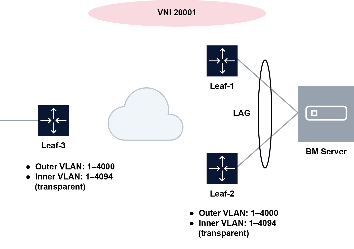
In this figure, the Bare Metal (BM) server is attached to a MAC VRF, and LAG-bridged subinterfaces are associated with the Dot1q VLAN range 1-4000. Traffic issued by the BM server with a VLAN ID matching any value in the configured range is associated with the bridged subinterface. VLAN IDs 4001-4095 are not associated with the subinterface.
The following figure shows a configuration with multiple VLAN ranges associated with a bridged subinterface.
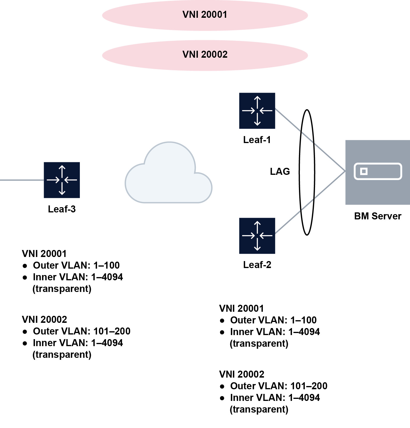
In this figure, VLAN ranges are selectively associated with a mac-vrf. VLAN IDs 1–100 are associated with MAC-VRF 20001 (which uses VNI 20001), and VLAN IDs 101–200 are associated with MAC-VRF 20002 (which uses VNI 20002).
In both figures, it is expected that all the leaf nodes attached to the same BD use the same VLAN ranges on all their bridged subinterfaces for the mac-vrf. The Dot1q VLAN tags of the incoming frames are not stripped off at the ingress subinterface. At the egress subinterface (which is configured with the same VLAN range as the ingress subinterface), no additional Dot1q tag is pushed onto the frames.
An SR Linux system can support up to 8,000 subinterfaces that have VLAN ranges, with up to 8 VLAN ranges per interface.
VLAN ranges can be configured on bridged subinterfaces of a mac-vrf with or without IRB subinterfaces. When an IRB subinterface is present in the same mac-vrf where the VLAN range subinterface is configured, incoming frames containing tags with a MAC DA equal to the IRB and associated with a Dot1q VLAN range subinterface are dropped. On egress, traffic coming from the IRB is not tagged if the destination is associated with a VLAN range subinterface.
VLAN ranges cannot overlap within the same subinterface or across subinterfaces of the same physical interface. In addition, ranges configured in subinterface a and individual VLAN ID values configured in a single-tagged subinterface b cannot overlap if a and b are defined in the same interface.
Configuring Dot1q VLAN ranges on a bridged subinterface
To configure a Dot1q VLAN range, specify the lower and upper values for the range. A subinterface can have multiple ranges associated with it.
The following example configures a range of VLAN IDs associated with a bridged subinterface. Traffic matching any VLAN in the range is associated with the bridged subinterface.
--{ candidate shared default }--[  ]--
# info interface ethernet-1/1
    interface ethernet-1/1 {
        vlan-tagging true
        subinterface 1 {
            type bridged
            vlan {
                encap {
                    single-tagged-range {
                        low-vlan-id 10 {
                            high-vlan-id 100
                        }
                    }
                }
            }
        }
    }
Displaying Dot1q VLAN range information
Check the Encapsulation field of the show interface command
for the configured Dot1q VLAN ranges for the interface.
--{ candidate shared default }--[  ]--
# show interface lag1.1
=================================================================================
  lag1.1 is up
    Network-instance: MAC-VRF-1
    Encapsulation   : vlan-id 1-10, 20-30
    Type            : bridged
=================================================================================