Shared Risk Link Groups for RSVP-Based LSPs
This chapter provides information about Shared Risk Link Groups for RSVP-Based LSPs.
Topics in this chapter include:
Applicability
This chapter was initially written for SR OS Release 7.0.R5, but the CLI in the current edition corresponds to SR OS Release 21.2.R1. There are no prerequisites.
Overview
Introduction
Shared Risk Link Group (SRLG) is a feature which allows the user to establish a backup secondary label switched path (LSP) or a fast-reroute (FRR) LSP which is disjoint from the primary LSP. Links which are members of the same SRLG represent resources which share the same risk. For example, fiber links sharing the same conduit or multiple wavelengths sharing the same fiber.
A typical application of the SRLG feature is to provide an automatic placement of secondary backup LSPs or FRR bypass/detour LSPs that minimizes the probability of fate sharing with the primary LSP.
SRLG groups are used to determine which links belong to the same SRLG. The mechanism is similar to Multi-Protocol Label Switching (MPLS) admin groups. To advertise SRLG, the information is part of the IGP TE parameters in an opaque link state advertisement (LSA). In IS-IS (RFC 4205, Intermediate System to Intermediate System (IS-IS) Extensions in Support of Generalized Multi-Protocol Label Switching (GMPLS)), the SRLG is advertised in a new Shared Risk Link Group TLV (type 138). In OSPF (RFC 4203, OSPF Extensions in Support of Generalized Multi-Protocol Label Switching (GMPLS)), the SRLG is advertised in a new SRLG sub-TLV (type 16) of the existing Link TLV.
For FRR, a choice can be made on what to do when no FRR tunnel can be found with the SRLG constraints. No FRR tunnel might be signaled or a FRR tunnel might be signaled not taking the SRLG constraints into account.
SRLG
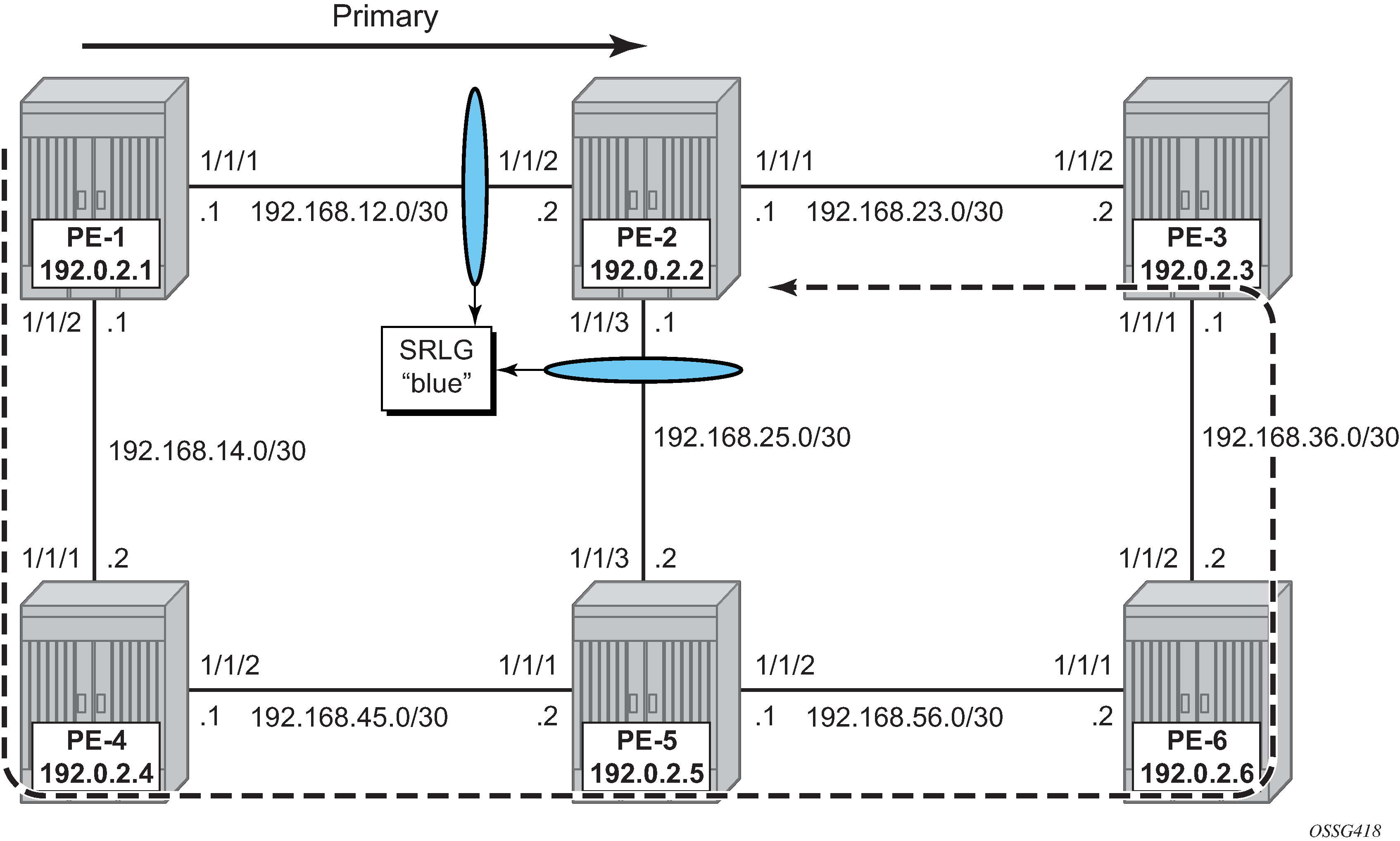
Example topology shows the example topology for this chapter.
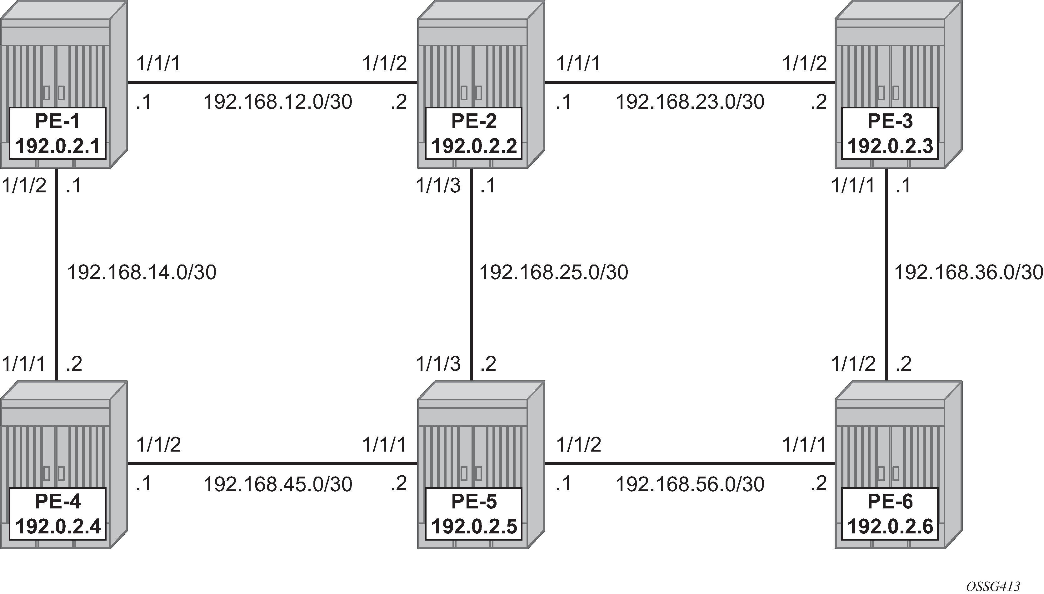
A single IGP area (IS-IS in this case) with traffic engineering (TE) enabled is required for the SRLG feature to work properly.
When OSPF is used as the IGP, the functionality is similar.
Configuration
Configuring the IP/MPLS network
IS-IS, MPLS, and RSVP are configured on all interfaces. TE is enabled in IS-IS. Optionally, admin groups ‟green” and ‟red” are configured on all nodes. The ‟green” links are the following: the link between PE-1 and PE-2, the link between PE-2 and PE-3, and the link between PE-3 and PE-6. The ‟red” links are: the link between PE-1 and PE-4, the link between PE-4 and PE-5, and the link between PE-5 and PE-6. The remaining link is the link between PE-2 and PE-5, which does not belong to an admin group. For more information about admin groups, see chapter .
In addition, ECMP is set to 2, instead of the default value 1 in order to highlight the application of SRLG in the final example: SRLG database.
# on PE-1:
configure
    router Base
        ecmp 2
Define SRLG groups
Define the SRLG groups, and link them to the related MPLS interfaces.
Two SRLG groups are defined, named blue and gray, as shown in SRLG topology.
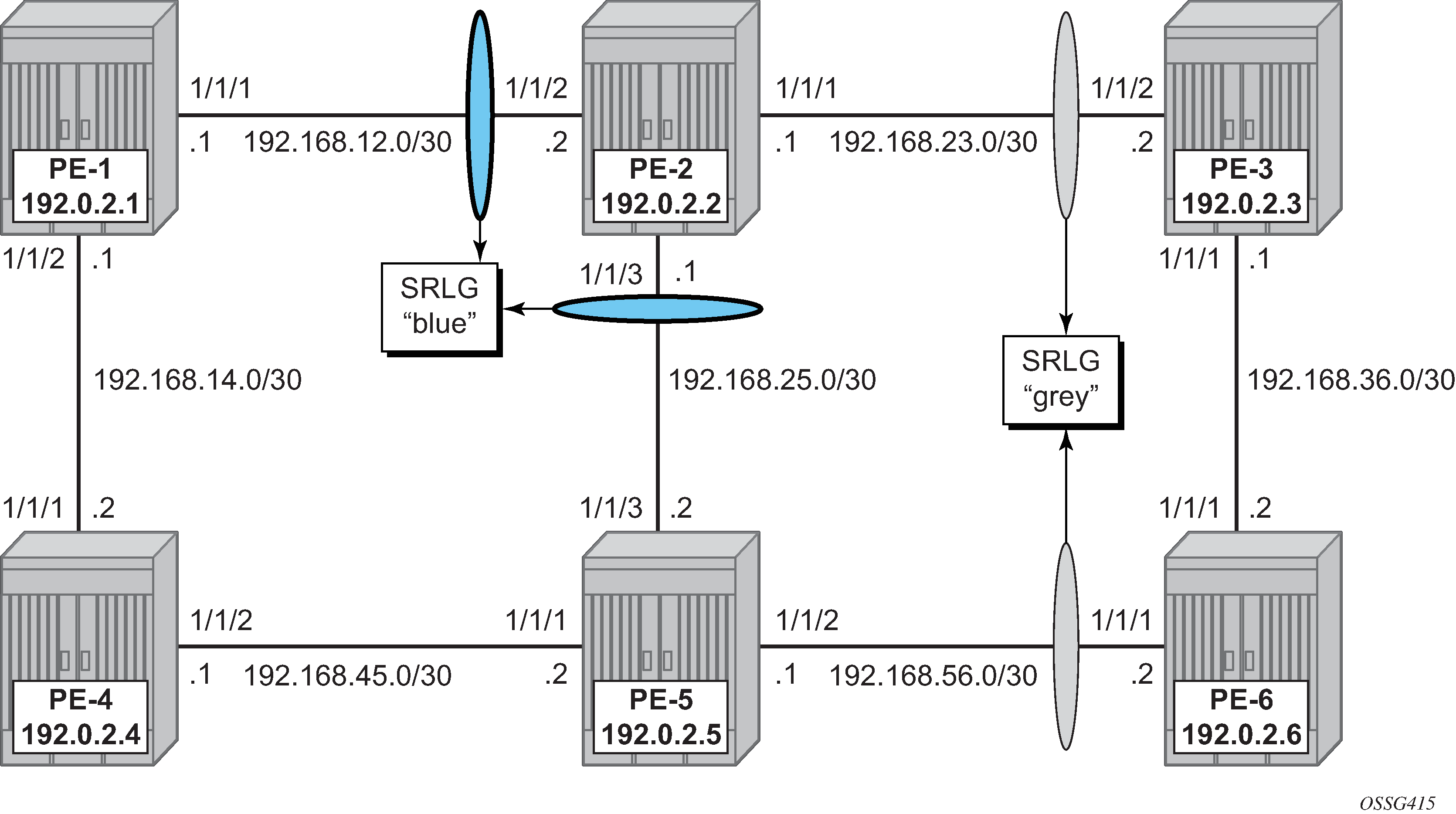
The configuration of the blue SRLG group is only mandatory on PE-1, PE-2, and PE-5, while the gray SRLG group is only mandatory on PE-2, PE-3, PE-5, and PE-6. However, it is good practice to configure both SRLG groups on all nodes, as follows:
# on all nodes:
configure
    router Base
        if-attribute
            srlg-group "blue" value 1
            srlg-group "gray" value 2
The IP/MPLS interfaces need to be linked to the related SRLG group, which is a uni-directional indicator, applying only to the egress direction; therefore, it needs to be configured on both sides of the IP/MPLS interface. For example, on PE-1, the interface to PE-2 is part of srlg-group ‟blue”. An interface can be part of multiple SRLG groups similar to the admin-group functionality.
# on PE-1:
configure
    router Base
        mpls
            interface "system"
                no shutdown
            exit
            interface "int-PE-1-PE-2"
                admin-group "green"
                srlg-group "blue"
                no shutdown
            exit
            interface "int-PE-1-PE-4"
                admin-group "red"
                no shutdown
            exit
            no shutdown
The same must be done on PE-2, PE-3, PE-5, and PE-6. Afterward, verify the MPLS configuration for example on PE-2, where the SRLG groups are linked to the interfaces. Admin groups are configured in parallel to indicate that both can be configured and will work independently.
# on PE-2:
configure
    router Base
        mpls
            interface "system"
                no shutdown
            exit
            interface "int-PE-2-PE-1"
                admin-group "green"
                srlg-group "blue"
                no shutdown
            exit
            interface "int-PE-2-PE-3"
                admin-group "green"
                srlg-group "gray"
                no shutdown
            exit
            interface "int-PE-2-PE-5"
                srlg-group "blue"
                no shutdown
            exit
            no shutdown
The SRLG configuration can be verified using the following show commands.
The following shows all SRLG groups on the node:
*A:PE-2# show router if-attribute srlg-group

======================================================================
Interface Srlg Groups
======================================================================
Group Name                       Group Value      Penalty Weight
----------------------------------------------------------------------
blue                             1                0
gray                             2                0
----------------------------------------------------------------------
No. of Groups: 2
======================================================================
In the following list of MPLS interfaces, admin groups and SRLG groups are indicated.
*A:PE-2# show router mpls interface

===============================================================================
MPLS Interfaces
===============================================================================
Interface                           Port-id           Adm  Opr(V4/V6) TE-
                                                                      metric
-------------------------------------------------------------------------------
system                              system            Up   Up/Down    None
  Admin Groups                      None
  SRLG Groups                       None
int-PE-2-PE-1                       1/1/2             Up   Up/Down    None
  Admin Groups                      green
  SRLG Groups                       blue
int-PE-2-PE-3                       1/1/1             Up   Up/Down    None
  Admin Groups                      green
  SRLG Groups                       gray
int-PE-2-PE-5                       1/1/3             Up   Up/Down    None
  Admin Groups                      None
  SRLG Groups                       blue
-------------------------------------------------------------------------------
Interfaces : 4
To verify the SRLG groups in the IGP TE database, the following command can be used. The output can be extensive, but searching on the SRLG group name will lead to the correct interfaces.
The following output shows the link-state advertisements of PE-2 on PE-1 in this case. The SRLG information is linked to the IP interfaces in a dedicated TE-TLV.
*A:PE-1# show router isis database PE-2.00-00 detail

===============================================================================
Rtr Base ISIS Instance 0 Database (detail)
===============================================================================

Displaying Level 1 database
-------------------------------------------------------------------------------
LSP ID    : PE-2.00-00                                  Level     : L1
Sequence  : 0x34                   Checksum  : 0xdfef   Lifetime  : 1051
Version   : 1                      Pkt Type  : 18       Pkt Ver   : 1
Attributes: L1                     Max Area  : 3        Alloc Len : 508
SYS ID    : 1920.0000.2002         SysID Len : 6        Used Len  : 508

TLVs :

---snip---

TE SRLGs     :
    SRLGs : PE-1.00
    Lcl Addr  : 192.168.12.2
    Rem Addr  : 192.168.12.1
    Num SRLGs       : 1
        1

---snip---

  TE SRLGs     :
    SRLGs : PE-3.00
    Lcl Addr  : 192.168.23.1
    Rem Addr  : 192.168.23.2
    Num SRLGs       : 1
        2

---snip---

  TE SRLGs     :
    SRLGs : PE-5.00
    Lcl Addr  : 192.168.25.1
    Rem Addr  : 192.168.25.2
    Num SRLGs       : 1
        1

---snip---
On-line verification
An on-line verification can be done by a tools perform command. This will trigger a Constrained Shortest Path First (CSPF) call to the Interior Gateway Protocol (IGP) TE database, and the result will be an Explicit Route Object (ERO) object which can potentially be used to set up a CSPF-based LSP.
The following shows the command syntax.
*A:PE-1# tools perform router mpls cspf ?
  - cspf to <ip-addr> [from <ip-addr>] [bandwidth <bandwidth>]
                      [include-bitmap <bitmap>] [exclude-bitmap <bitmap>]
                      [hop-limit <limit>]
                      [exclude-address <excl-addr> [<excl-addr>...(up to 8 max)]]
                      [use-te-metric]
                      [strict-srlg]
                      [srlg-group <grp-id>...(up to 8 max)]
                      [exclude-node <excl-node-id> [<excl-node-id>..(up to 8 max)]]
                      [skip-interface <interface-name>]
                      [ds-class-type <class-type>]
                      [cspf-reqtype <req-type>]
                      [least-fill-min-thd <thd>]
                      [setup-priority <val>]
                      [hold-priority <val>]

 <ip-addr>            : a.b.c.d
 <rate-in-mbps>       : [0..6400000]
 <bitmap>             : [0..4294967295] - accepted in decimal, hex(0x) or binary(0b)
 <limit>              : [2..255]
 <excl-addr>          : a.b.c.d (outbound interface)
 <metric-type-te>     : keyword
 <strict-srlg>        : keyword
 <grp-id>             : [0..4294967295]
 <excl-node-id>       : [a.b.c.d] (outbound interface)
 <interface-name>     : [max 32 chars]
 <class-type>         : [0..7]
 <req-type>           : all|random|least-fill : keywords
 <thd>                : [1..100]
 <priority>           : [0..7]
Where the relevant parameters are:
to — Defines the far-end address of the LSP. This is the system-address of the destination LER
srlg-group — Specifies which SRLG groups should be avoided while building the path to the destination (ERO object)
strict-srlg — Indicates whether the SRLG group is a strict requirement or not. When this parameter is given, only paths without traversing the SRLG will be displayed.
Example:
On PE-1, a CSPF calculation is made with PE-3 as destination, without any SRLG restrictions, as follows:
*A:PE-1# tools perform router mpls cspf to 192.0.2.3
Req CSPF for all ECMP paths
    from: this node to: 192.0.2.3 w/(no Diffserv) class: 0 , setup Priority 7,
                                                  Hold Priority 0 TE Class: 7

CSPF Path
To        : 192.0.2.3
Path 1    : (cost 20)
    Src:   192.0.2.1   (= Rtr)
    Egr:   192.168.12.1       -> Ingr:   192.168.12.2         Rtr:   192.0.2.2      (met 10)
    Egr:   192.168.23.1       -> Ingr:   192.168.23.2         Rtr:   192.0.2.3      (met 10)
    Dst:   192.0.2.3   (= Rtr)
With a restriction on srlg-group "blue" (grp-id =1), the CSPF calculation is as follows:
*A:PE-1# tools perform router mpls cspf to 192.0.2.3 srlg-group 1
Req CSPF for all ECMP paths
    from: this node to: 192.0.2.3 w/(no Diffserv) class: 0 , setup Priority 7,
                                                  Hold Priority 0 TE Class: 7

CSPF Path
To        : 192.0.2.3
Path 1    : (cost 40)
    Src:   192.0.2.1   (= Rtr)
    Egr:   192.168.14.1         -> Ingr:   192.168.14.2       Rtr:   192.0.2.4      (met 10)
    Egr:   192.168.45.1         -> Ingr:   192.168.45.2       Rtr:   192.0.2.5      (met 10)
    Egr:   192.168.56.1         -> Ingr:   192.168.56.2       Rtr:   192.0.2.6      (met 10)
      1 SRLGs:  2
    Egr:   192.168.36.2         -> Ingr:   192.168.36.1       Rtr:   192.0.2.3      (met 10)
    Dst:   192.0.2.3   (= Rtr)
The path will be through PE-4, PE-5, and PE-6.
When a strict restriction is requested on srlg-group "gray", no valid CSPF path toward the destination can be found.
*A:PE-1# tools perform router mpls cspf to 192.0.2.3 srlg-group 2 strict-srlg
Req CSPF for all ECMP paths
    from: this node to: 192.0.2.3 w/(no Diffserv) class: 0 , setup Priority 7,
                                                  Hold Priority 0 TE Class: 7

MINOR: CLI No CSPF path to "192.0.2.3" with specified constraints.
Removing the strict restriction results in a successful return of CSPF, indicating that the CSPF path is not SRLG disjoint.
*A:PE-1# tools perform router mpls cspf to 192.0.2.3 srlg-group 2
Req CSPF for all ECMP paths
    from: this node to: 192.0.2.3 w/(no Diffserv) class: 0 , setup Priority 7,
    Hold Priority 0 TE Class: 7

CSPF Path
To        : 192.0.2.3 (NOT SRLG DISJOINT)
Path 1    : (cost 20)
    Src:   192.0.2.1   (= Rtr)
    Egr:   192.168.12.1         -> Ingr:   192.168.12.2         Rtr:   192.0.2.2     (met 10)
      1 SRLGs:  1
    Egr:   192.168.23.1         -> Ingr:   192.168.23.2         Rtr:   192.0.2.3     (met 10)
      1 SRLGs:  2
    Dst:   192.0.2.3   (= Rtr)
The best practice for debugging is to enable debug-tracing on the CSPF process, with following command:
# on PE-1:
debug
    router Base
        isis 0
            cspf
SRLG for FRR
The fast-reroute mechanism used here is facility link protection (fast-reroute facility no node-protect). The SRLG feature is independent of the FRR type and works for all combinations (facility versus one-to-one, link versus node protection).
Configure an LSP from PE-1 to PE-3, and enable CSPF.
The configuration of the LSP "LSP-PE-1-PE-3_FRR_facility-link" is based on an empty path, with FRR facility link protection enabled.
# on PE-1:
configure
    router Base
        mpls
            path "dyn"
                no shutdown
            exit
            lsp "LSP-PE-1-PE-3_FRR_facility-link"
                to 192.0.2.3
                path-computation-method local-cspf
                fast-reroute facility
                    no node-protect
                exit
                primary "dyn"
                exit
                no shutdown
            exit
To verify the primary path, oam lsp-trace command can be used, checking the intermediate nodes.
*A:PE-1# oam lsp-trace "LSP-PE-1-PE-3_FRR_facility-link" detail
lsp-trace to LSP-PE-1-PE-3_FRR_facility-link: 0 hops min, 0 hops max, 116 byte packets1  192.0.2.2  rtt=2.46ms rc=8(DSRtrMatchLabel) rsc=1
 DS 1: ipaddr=192.168.23.2 ifaddr=192.168.23.2 iftype=ipv4Numbered MRU=1564
 label[1]=524287 protocol=4(RSVP-TE)
2  192.0.2.3  rtt=3.99ms rc=3(EgressRtr) rsc=1
To verify if the bypass tunnels are up and running, an indication (@) can be found in the detail output of show router mpls ls <x> path detail as seen in the following output.
*A:PE-1# show router mpls lsp "LSP-PE-1-PE-3_FRR_facility-link" path detail

===============================================================================
MPLS LSP LSP-PE-1-PE-3_FRR_facility-link Path  (Detail)
===============================================================================
Legend :
    @ - Detour Available              # - Detour In Use
    b - Bandwidth Protected           n - Node Protected
    s - Soft Preemption
    S - Strict                        L - Loose
    A - ABR                           + - Inherited
===============================================================================
-------------------------------------------------------------------------------
LSP LSP-PE-1-PE-3_FRR_facility-link
Path dyn
-------------------------------------------------------------------------------
LSP Name    : LSP-PE-1-PE-3_FRR_facility-link
From             : 192.0.2.1
To               : 192.0.2.3
Admin State      : Up                      Oper State        : Up
Path Name   : dyn
Path LSP ID      : 40960                   Path Type         : Primary
Path Admin       : Up                      Path Oper         : Up
Out Interface    : 1/1/1                   Out Label         : 524280

---snip---

Explicit Hops    :
    No Hops Specified
Actual Hops      :
    192.168.12.1(192.0.2.1) @                    Record Label        : N/A
 -> 192.168.12.2(192.0.2.2) @                    Record Label        : 524280
 -> 192.168.23.2(192.0.2.3)                      Record Label        : 524281
Computed Hops    :
    192.168.12.1(S)
 -> 192.168.12.2(S)
 -> 192.168.23.2(S)
Resignal Eligible: False
Last Resignal    : n/a                     CSPF Metric       : 20
===============================================================================
* indicates that the corresponding row element may have been truncated.
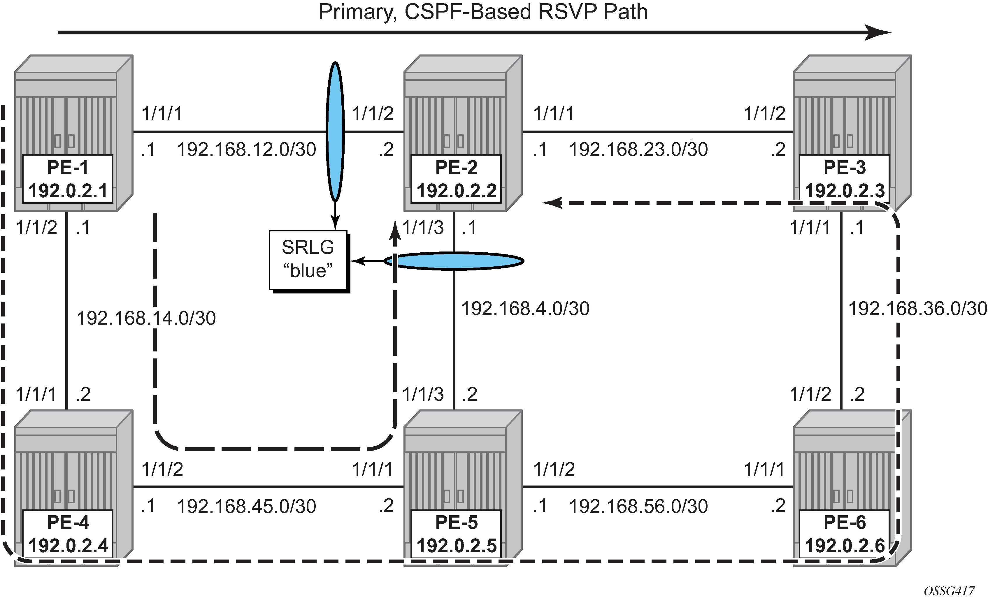
Two links are protected: one bypass tunnel originates in PE-1 protecting the link between PE-1 and PE-2. Another bypass tunnel originates in PE-2 protecting the link between PE-2 and PE-3. The focus is on the bypass tunnel originating in PE-1. When SRLG is enabled, the bypass tunnel originating in PE-1 will have different hops. The expected paths followed by the bypass tunnels originating in PE-1 with and without SRLG are shown in FRR bypass tunnels originating in PE-1 with and without SRLG.
To verify the bypass data path on the point of local repair (PLR) PE-1, the following command can be used.
*A:PE-1# show router mpls bypass-tunnel detail

===============================================================================
MPLS Bypass Tunnels (Detail)
===============================================================================
-------------------------------------------------------------------------------
bypass-link192.168.12.2-61441
-------------------------------------------------------------------------------
To             : 192.168.25.1        State               : Up
Out I/F        : 1/1/2               Out Label           : 524280
Up Time        : 0d 00:11:31         Active Time         : n/a
Reserved BW    : 0 Kbps              Protected LSP Count : 1
Type           : Dynamic             Bypass Path Cost    : 30
Setup Priority : 7                   Hold Priority       : 0
Class Type     : 0
Exclude Node   : None                Inter-Area          : False
Computed Hops  :
    192.168.14.1(S)                  Egress Admin Groups :
                                     red
 -> 192.168.14.2(S)                  Egress Admin Groups :
                                     red
 -> 192.168.45.2(S)                  Egress Admin Groups : None
 -> 192.168.25.1(S)                  Egress Admin Groups : None
Actual Hops    :
    192.168.14.1 (192.0.2.1)         Record Label        : N/A
 -> 192.168.14.2 (192.0.2.4)         Record Label        : 524280
 -> 192.168.45.2 (192.0.2.5)         Record Label        : 524279
 -> 192.168.25.1 (192.0.2.2)         Record Label        : 524279
Last Resignal  :
Attempted At   : n/a                 Resignal Reason     : n/a
Resignal Status: n/a                 Reason              : n/a

===============================================================================
The SRLG restriction is not taken into account at this moment at PLR PE-1. The actual hops are PE-4, PE-5, and PE-2 visualized by the path with the long dashes in FRR bypass tunnels originating in PE-1 with and without SRLG.
To take the SRLG restrictions into account, the following additional configuration is needed for MPLS on PE-1.
*A:PE-1>config>router>mpls# srlg-
srlg-database  srlg-frr

*A:PE-1>config>router>mpls# srlg-frr ?
  - no srlg-frr
  - srlg-frr [strict]

 <strict>             : keyword
# on PE-1:
configure
    router Base
        mpls
            srlg-frr strict
The option strict should only be used if the logical topology allows this. In other words, one must be sure that an alternative path is possible which avoids SRLG-groups.
Note: Enabling or disabling SRLG for FRR is a system-wide configuration and requires the MPLS routing instance to be manually disabled (shutdown) and then re-enabled (no shutdown) to activate the change. This may cause service outage. Nokia recommends that the operator incorporates the SRLG into the initial network design and implementation to minimize the traffic loss.
# on all nodes:
configure
    router Base
        rsvp
            shutdown
            no shutdown
The bypass tunnel originating in PLR PE-1 can be verified with a previously used command.
*A:PE-1# show router mpls bypass-tunnel detail

===============================================================================
MPLS Bypass Tunnels (Detail)
===============================================================================
-------------------------------------------------------------------------------
bypass-link192.168.12.2-61442
-------------------------------------------------------------------------------
To             : 192.168.23.1        State               : Up
Out I/F        : 1/1/2               Out Label           : 524280
Up Time        : 0d 00:00:42         Active Time         : n/a
Reserved BW    : 0 Kbps              Protected LSP Count : 1
Type           : Dynamic             Bypass Path Cost    : 50
Setup Priority : 7                   Hold Priority       : 0
Class Type     : 0
Exclude Node   : None                Inter-Area          : False
Computed Hops  :
    192.168.14.1(S)                  Egress Admin Groups :
                                     red
 -> 192.168.14.2(S)                  Egress Admin Groups :
                                     red
 -> 192.168.45.2(S)                  Egress Admin Groups :
                                     red
 -> 192.168.56.2(S)                  Egress Admin Groups :
                                     green
 -> 192.168.36.1(S)                  Egress Admin Groups :
                                     green
 -> 192.168.23.1(S)                  Egress Admin Groups : None
Actual Hops    :
    192.168.14.1 (192.0.2.1)         Record Label        : N/A
 -> 192.168.14.2 (192.0.2.4)         Record Label        : 524280
 -> 192.168.45.2 (192.0.2.5)         Record Label        : 524279
 -> 192.168.56.2 (192.0.2.6)         Record Label        : 524280
 -> 192.168.36.1 (192.0.2.3)         Record Label        : 524279
 -> 192.168.23.1 (192.0.2.2)         Record Label        : 524279
Last Resignal  :
Attempted At   : n/a                 Resignal Reason     : n/a
Resignal Status: n/a                 Reason              : n/a

===============================================================================
This path taking the SRLG constraints into account is represented by the line with the short dashes in FRR bypass tunnels originating in PE-1 with and without SRLG.
SRLG for standby path
Where SRLG groups can be constraints for bypass tunnels, they can also be a constraint to set up a secondary path. SRLG for secondary path shows that the secondary path is expected to follow the dashed line instead of passing over the direct link between PE-5 and PE-2.
An LSP is configured with a primary and a secondary path, which have no hops defined. The configuration of the LSP will need a specific indication at the level of the secondary path to enable the restriction on the srlg-groups.
# on PE-1:
configure
    router
        mpls
            path "prim"
                no shutdown
            exit
            path "secon"
                no shutdown
            exit
            lsp "LSP-PE-1-PE-2-srlg"
                to 192.0.2.2
                path-computation-method local-cspf
                primary "prim"
                exit
                secondary "secon"
                    standby
                    srlg
                exit
                no shutdown
            exit
Where both paths are empty paths, the ERO object creation solely relies on CPSF without any specific hop.
To verify the data path, the detailed output of the show router mpls lsp <..> path command can be used, as well as the lsp-trace OAM command. This output shows both ERO objects of the primary and secondary path.
*A:PE-1# show router mpls lsp "LSP-PE-1-PE-2-srlg" path detail

===============================================================================
MPLS LSP LSP-PE-1-PE-2-srlg Path  (Detail)
===============================================================================
Legend :
    @ - Detour Available              # - Detour In Use
    b - Bandwidth Protected           n - Node Protected
    s - Soft Preemption
    S - Strict                        L - Loose
    A - ABR                           + - Inherited
===============================================================================
-------------------------------------------------------------------------------
LSP LSP-PE-1-PE-2-srlg
Path prim
-------------------------------------------------------------------------------
---snip---

Explicit Hops    :
    No Hops Specified
Actual Hops      :
    192.168.12.1(192.0.2.1)                      Record Label        : N/A
 -> 192.168.12.2(192.0.2.2)                      Record Label        : 524278
Computed Hops    :
    192.168.12.1(S)
 -> 192.168.12.2(S)
Resignal Eligible: False
Last Resignal    : n/a                     CSPF Metric       : 10
-------------------------------------------------------------------------------
LSP LSP-PE-1-PE-2-srlg
Path secon
-------------------------------------------------------------------------------
---snip---

Explicit Hops    :
    No Hops Specified
Actual Hops      :
    192.168.14.1(192.0.2.1)                      Record Label        : N/A
 -> 192.168.14.2(192.0.2.4)                      Record Label        : 524279
 -> 192.168.45.2(192.0.2.5)                      Record Label        : 524278
 -> 192.168.56.2(192.0.2.6)                      Record Label        : 524279
 -> 192.168.36.1(192.0.2.3)                      Record Label        : 524278
 -> 192.168.23.1(192.0.2.2)                      Record Label        : 524277
Computed Hops    :
    192.168.14.1(S)
 -> 192.168.14.2(S)
 -> 192.168.45.2(S)
 -> 192.168.56.2(S)
 -> 192.168.36.1(S)
 -> 192.168.23.1(S)
Srlg             : Enabled                 Srlg Disjoint     : True
Resignal Eligible: False
Last Resignal    : n/a                     CSPF Metric       : 50
===============================================================================
The lsp-trace command can be used for secondary path as well. The intermediate LSRs and the MPLS labels used can be clearly seen.
*A:PE-1# oam lsp-trace "LSP-PE-1-PE-2-srlg" path "secon" detail
lsp-trace to LSP-PE-1-PE-2-srlg: 0 hops min, 0 hops max, 116 byte packets
1  192.0.2.4  rtt=2.53ms rc=8(DSRtrMatchLabel) rsc=1
     DS 1: ipaddr=192.168.45.2 ifaddr=192.168.45.2 iftype=ipv4Numbered MRU=1564
           label[1]=524285 protocol=4(RSVP-TE)
2  192.0.2.5  rtt=3.89ms rc=8(DSRtrMatchLabel) rsc=1
     DS 1: ipaddr=192.168.56.2 ifaddr=192.168.56.2 iftype=ipv4Numbered MRU=1564
           label[1]=524285 protocol=4(RSVP-TE)
3  192.0.2.6  rtt=4.57ms rc=8(DSRtrMatchLabel) rsc=1
     DS 1: ipaddr=192.168.36.1 ifaddr=192.168.36.1 iftype=ipv4Numbered MRU=1564
           label[1]=524287 protocol=4(RSVP-TE)
4  192.0.2.3  rtt=4.39ms rc=8(DSRtrMatchLabel) rsc=1
     DS 1: ipaddr=192.168.23.1 ifaddr=192.168.23.1 iftype=ipv4Numbered MRU=1564
           label[1]=524284 protocol=4(RSVP-TE)
5  192.0.2.2  rtt=4.75ms rc=3(EgressRtr) rsc=1
SRLG database
In case not all IP/MPLS routers in the area support SRLG, a static SRLG database can be created on the systems which will be used as an additional constraint when performing the CSPF calculation to define the path.
SRLG database example shows an example where an additional SRLG group ‟red” is defined on PE-1, with information related to the interface between PE-4 and PE-5.
# on PE-1:
configure
    router Base
        if-attribute
            srlg-group "red" value 3
        exit
        mpls
            interface "int-PE-1-PE-4"
                srlg-group "red"
            exit
            srlg-database
                router-id 192.0.2.4
                    interface 192.168.45.1 srlg-group "red"
                    no shutdown
                exit
                router-id 192.0.2.5
                    interface 192.168.45.2 srlg-group "red"
                    no shutdown
                exit
            exit
This information is local to PE-1 and will only have effect on CSPF calculations on PE-1, not on the other nodes.
When a CSPF calculation is done for a path from PE-1 to PE-5, the result will be two equal-cost paths, because ECMP equals 2. When adding the srlg-group ‟red” as a restriction, only a single path will be found, passing PE-2.
Conclusion
Interpreting the SRLG information into the TE database makes it possible to protect an LSP even when multiple IP/MPLS interfaces fail as a result of an underlying transmission failure. Transmission failures can occur quite often because not all transmission links are one to one protected.
SRLG groups in MPLS provide a very dynamic and simple way to assure LSP FRR path protection on every PLR throughout the followed LSP. The SRLG groups are also taken into account when defining the ERO for secondary paths, at least if the configured secondary path is empty.
For interoperability reasons, the SRLG-database is available, because systems can link interfaces to an SRLG with interconnecting systems that do not support the SRLG feature; so they cannot advertise the SRLG information through the IGP.
The creation and maintenance of an SRLG database requires operational effort and systems that do not support SRLG will never take any SRLG information into account during CSPF calculation for the creation of FRR bypass or detour tunnels.