LDP-SR Stitching for IPv4 Prefixes (IS-IS)
This chapter provides information about LDP-SR Stitching for IPv4 Prefixes (IS-IS).
Topics in this chapter include:
Applicability
This chapter was initially written for SR OS Release 14.0.R5. The CLI in the current edition is based on SR OS Release 21.2.R1.
Overview
Segment Routing (SR) allows for the construction of source-routed Label Switched Paths (LSPs) where the series of hops to be taken through the network are indicated by one or more Segment Identifiers (SIDs) assigned at the ingress PE. In the case of an MPLS data plane, these SIDs are MPLS labels learned through extensions to the OSPF/IS-IS control plane. SR provides benefits to the MPLS data plane, such as high scalability (due to lack of soft-state), traffic engineering capability, and topology-independent fast reroute.
When SR is configured in an IP/MPLS network that runs the Label Distribution Protocol (LDP), it is possible that SR and LDP will coexist, in which case preference for LDP or SR is a local matter at the LSP head end. It is equally possible that not all devices will have the capability to support SR, in which case some kind of interworking between SR and LDP is necessary to create an end-to-end LSP. Fast reroute coverage can also benefit from this SR-LDP interworking function, where SR is used to increase Loop Free Alternate (LFA) coverage using Remote or Directed LFA.
This chapter describes the configuration requirements for the interworking of LDP and SR to form a single end-to-end LSP when using IS-IS as an IGP. The chapter shows how this interworking function can be used to extend fast reroute coverage for LDP-based LSPs.
Configuration
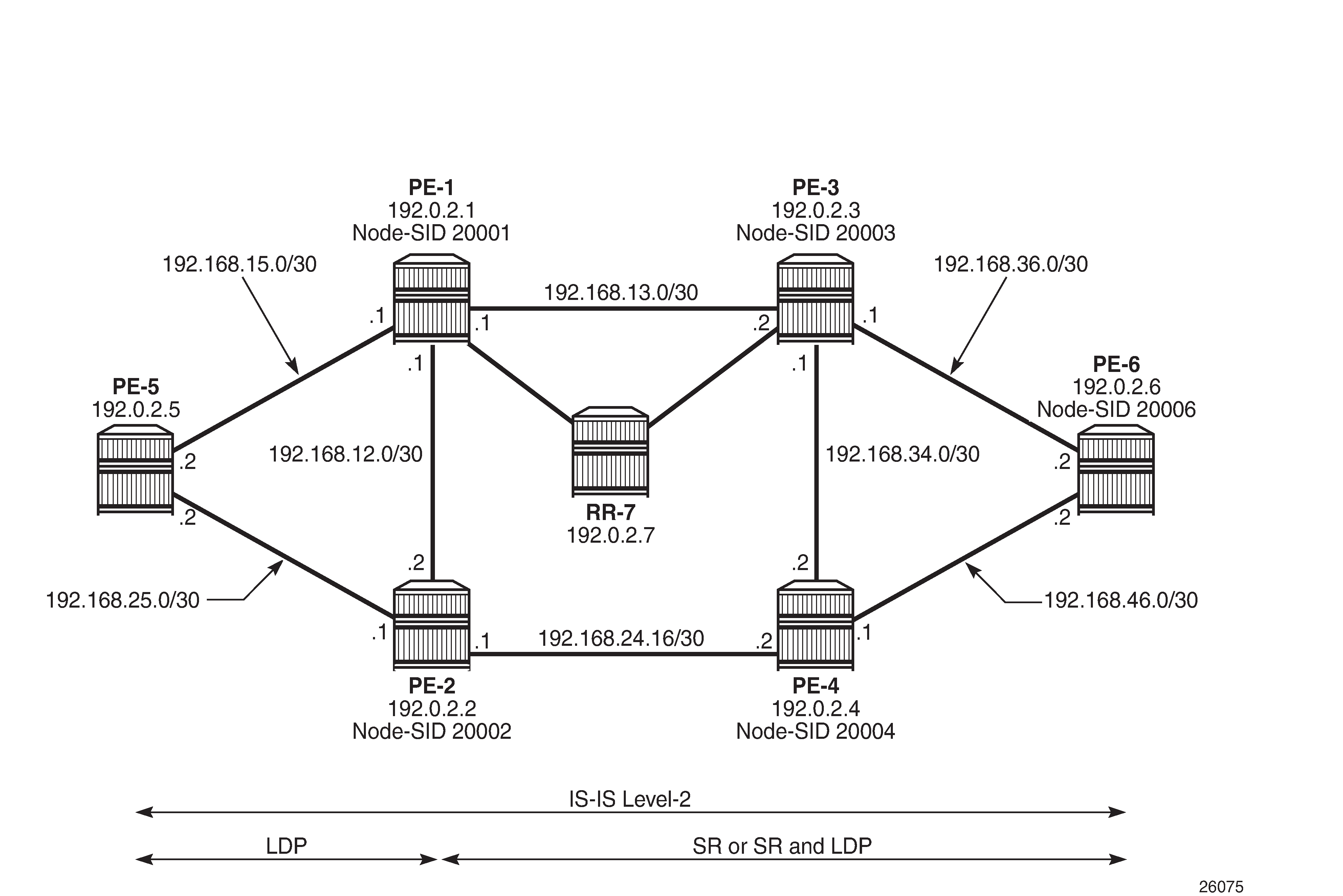
Example topology
The topology shown in Example topology provides an example of SR-LDP interworking. All routers within the topology form part of Autonomous System 64496 and are IBGP clients of RR-7 for the VPN-IPv4 address family. All routers in the topology belong to the same IS-IS Level-2 area, and all link metrics are set to 100. RR-7 does not participate in any MPLS data plane, and signals the IS-IS overload bit to avoid being used for transit traffic.
PE-5 is a router that does not support SR and, therefore, runs only LDP to its connected peers PE-1 and PE-2. PE-1, PE-2, PE-3, PE-4, and PE-6 are capable of running both SR and LDP, but are initially configured to only run SR with the associated node-SIDs shown in Example topology. When explicitly described, LDP will be enabled in conjunction with SR on these routers to show the difference between the two approaches, and to show how SR can be used as a fast reroute backup for SR primary LSPs.
The LDP configuration at PE-1 toward PE-5 is shown in the following output. The configuration at PE-2 is similar with the only exception being IP addressing.
# on PE-1:
configure
    router
        ldp
            interface-parameters
                interface "int-PE-1-PE-5" dual-stack
                    ipv4
                        no shutdown
                    exit
                    no shutdown
                exit
            exit
            targeted-session
            exit
            no shutdown
        exit
PE-1, PE-2, PE-3, PE-4, and PE-6 run SR. The following output provides an example of the relevant SR configuration parameters at PE-1, with similar configurations on the remaining SR routers. For a description of these parameters, see chapter Segment Routing with IS-IS Control Plane.
# on PE-1:
configure
    router
        mpls-labels
            sr-labels start 20000 end 20099
        exit
        isis
            area-id 49.0001
            advertise-router-capability as
            level 2
                wide-metrics-only
            exit
            segment-routing
                prefix-sid-range start-label 20000 max-index 99
                no shutdown
            exit
            interface "system"
                level-capability level-2
                ipv4-node-sid label 20001
                passive
                no shutdown
            exit
            interface "int-PE-1-PE-2"
                level-capability level-2
                interface-type point-to-point
                level 2
                    metric 100
                exit
                no shutdown
            exit
            interface "int-PE-1-PE-3"
                level-capability level-2
                interface-type point-to-point
                level 2
                    metric 100
                exit
                no shutdown
            exit
            interface "int-PE-1-PE-5"
                level-capability level-2
                interface-type point-to-point
                level 2
                    metric 100
                exit
                no shutdown
            exit
            interface "int-PE-1-RR-7"
                level-capability level-2
                interface-type point-to-point
                level 2
                    metric 100
                exit
                no shutdown
            exit
            no shutdown
        exit
SR Mapping Server
An SR Mapping Server (SR-MS) is an integral part of SR-LDP interoperability and has the responsibility for advertising prefixes to SID/label mappings on behalf of routers that do not support SR. When using IS-IS, a SID/label-binding TLV (TLV 149) containing a prefix-SID sub-TLV is used to advertise one or more SID index/labels and one or more prefixes. In the example topology, PE-4 is selected as the SR-MS and will advertise a prefix SID for the non-SR-capable router, PE-5.
The following output provides an example of the configuration required to implement SR-MS functionality. Under the segment-routing node, a mapping-server context is created that allows for origination of a SID/label-binding TLV and prefix-SID sub-TLV. The syntax begins with sid-map node-sid and is followed by an index. In SR OS, prefix-SIDs are always advertised with an index value (as opposed to an absolute label value), and the formula {start-label + SID index} is used to derive the label value. In this example, index 5 is used and, therefore, the derived label value is {20000+5} 20005 for the PE-5 prefix 192.0.2.5/32.
An optional range argument allows for advertisement of a contiguous range of prefixes and associated SIDs using the configured index/prefix as the beginning of the range. Non-contiguous ranges require multiple entries and are advertised as separate SID/label-binding TLVs. An additional optional set-flags s argument can also be used to set the S-flag, which controls the flooding scope. When set, the flooding scope is the entire IS-IS domain. When not set, the flooding scope is the IS-IS level into which the TLV was advertised.
# on PE-4:
configure
    router
        isis
            segment-routing
                prefix-sid-range start-label 20000 max-index 99
                mapping-server
                    sid-map node-sid index 5 prefix 192.0.2.5/32
                    no shutdown
                exit
                no shutdown
            exit
            no shutdown
        exit
The relevant part of the IS-IS LSP generated by PE-4, showing the SID/label-binding TLV, is shown in the following output:
*A:PE-4# show router isis database PE-4.00-00 detail

===============================================================================
Rtr Base ISIS Instance 0 Database (detail)
===============================================================================
---snip---
Displaying Level 2 database
-------------------------------------------------------------------------------
LSP ID    : PE-4.00-00                                  Level     : L2
Sequence  : 0x6                    Checksum  : 0xf35f   Lifetime  : 1177
Version   : 1                      Pkt Type  : 20       Pkt Ver   : 1
Attributes: L1L2                   Max Area  : 3        Alloc Len : 1492
SYS ID    : 1920.0000.2004         SysID Len : 6        Used Len  : 258
---snip---
TLVs :
  Area Addresses:
    Area Address : (3) 49.0001
  Supp Protocols:
    Protocols     : IPv4
  IS-Hostname   : PE-4
  Router ID   :
    Router ID   : 192.0.2.4
  Router Cap : 192.0.2.4, D:0, S:0
    TE Node Cap : B E M  P
    SR Cap: IPv4 MPLS-IPv6
       SRGB Base:20000, Range:100
    SR Alg: metric based SPF
    Node MSD Cap: BMI : 12 ERLD : 15
  SID Label Binding:
    Prefix: 192.0.2.5/32 Range:1 Weight:0 bFlgs:v4 SID:5 Algo:0 pFlgs:N
---snip---
Level (2) LSP Count : 1
-------------------------------------------------------------------------------
Control Info     : D = Prefix Leaked Down
                   S = Sub-TLVs Present
Attribute Flags  : N = Node Flag
                   R = Re-advertisement Flag
                   X = External Prefix Flag
                   E = Entropy Label Capability (ELC) Flag
Adj-SID Flags    : v4/v6 = IPv4 or IPv6 Address-Family
                   B = Backup Flag
                   V = Adj-SID carries a value
                   L = value/index has local significance
                   S = Set of Adjacencies
                   P = Persistently allocated
Prefix-SID Flags : R = Re-advertisement Flag
                   N = Node-SID Flag
                   nP = no penultimate hop POP
                   E = Explicit-Null Flag
                   V = Prefix-SID carries a value
                   L = value/index has local significance
Lbl-Binding Flags: v4/v6 = IPv4 or IPv6 Address-Family
                   M = Mirror Context Flag
                   S = SID/Label Binding flooding
                   D = Prefix Leaked Down
                   A = Attached Flag
SABM-flags Flags:  R = RSVP-TE
                   S = SR-TE
                   F = LFA
                   X = FLEX-ALGO
FAD-flags Flags:   M = Prefix Metric
===============================================================================
At other routers within the SR domain, the presence of the advertised prefix can be validated as shown in the following output taken at PE-1. The SRMS field is set to Y for prefix 192.0.2.5/32, indicating that the prefix was advertised by an SR-MS. (In the case of IS-IS, the prefix-SID is a sub-TLV of the SID/label-binding TLV and the "N" (node-SID) flag is set; therefore, it can be recognized as being advertised by a mapping server.) The Y is followed by an "(S)" flag, indicating that the SRMS prefix-SID is selected to be programmed. This indication is provided in case there are multiple advertisements for the same prefix and/or node-SID from different SR mapping servers that result in some kind of conflict or inconsistency. If there are multiple mapping servers advertising the same prefix-SID, the advertising router with the lowest system/router ID is preferred.
*A:PE-1# show router isis prefix-sids

===============================================================================
Rtr Base ISIS Instance 0 Prefix/SID Table
===============================================================================
Prefix                            SID        Lvl/Typ    SRMS   AdvRtr
                                                         MT     Flags
-------------------------------------------------------------------------------
192.0.2.1/32                      1          2/Int.      N     PE-1
                                                            0      NnP
192.0.2.2/32                      2          2/Int.      N     PE-2
                                                            0      NnP
192.0.2.3/32                      3          2/Int.      N     PE-3
                                                            0      NnP
192.0.2.4/32                      4          2/Int.      N     PE-4
                                                            0      NnP
192.0.2.5/32                      5          2/Int.      Y(S)  PE-4
                                                            0      NnP
192.0.2.6/32                      6          2/Int.      N     PE-6
                                                            0      NnP
-------------------------------------------------------------------------------
No. of Prefix/SIDs: 6 (6 unique)
-------------------------------------------------------------------------------
SRMS : Y/N  = prefix SID advertised by SR Mapping Server (Y) or not (N)
          S    = SRMS prefix SID is selected to be programmed
Flags: R    = Re-advertisement
       N    = Node-SID
       nP   = no penultimate hop POP
       E    = Explicit-Null
       V    = Prefix-SID carries a value
       L    = value/index has local significance
===============================================================================
SR-LDP interworking
Interworking SR and LDP essentially consists of stitching an LDP FEC and an SR node-SID route for the same prefix. In the example topology, PE-1 and PE-2 will act as the SR-LDP interworking nodes.
In the LDP-to-SR data plane direction, LDP uses an export-tunnel-table command under the ldp context to reference a policy that defines which prefixes should be redistributed from the IS-IS/SR domain into LDP. When applied, the LDP process monitors the tunnel-table until it locates a /32 SR tunnel of type sr-isis that matches a prefix defined in the export policy. LDP then programs an LDP Incoming Label Map (ILM) entry and stitches it to the SR node-SID tunnel endpoint. The LDP process also originates a FEC for the prefix and advertises that FEC to its peers.
The following output provides an example of the route policy and application of the policy at PE-1 and PE-2. In this policy, PE-1 advertises LDP FECs to PE-5 for PE-3 (192.0.2.3), PE-4 (192.0.2.4), and PE-6 (192.0.2.6), provided that PE-1 has a /32 SR tunnel of type sr-isis in the tunnel-table for those same prefixes. PE-1 also programs an LDP ILM entry for each prefix and stitches it to the appropriate SR tunnel.
# on PE-1 and PE-2:
configure
    router
        policy-options
            begin
            prefix-list "sr-domain-prefixes"
                prefix 192.0.2.3/32 exact
                prefix 192.0.2.4/32 exact
                prefix 192.0.2.6/32 exact
            exit
            policy-statement "SR-to-LDP-policy"
                entry 10
                    from
                        protocol isis
                        prefix-list "sr-domain-prefixes"
                    exit
                    to
                        protocol ldp
                    exit
                    action accept
                    exit
                exit
            exit
            commit
        exit
        ldp
            export-tunnel-table "SR-to-LDP-policy"
        exit
    exit all
In the SR-to-LDP data plane direction, the export-tunnel-table ldp command within the segment-routing context is the only required configuration. Unlike the LDP-to-SR data plane direction, where policy is used to control which prefixes are stitched, in the SR-to-LDP direction, no policy is explicitly referenced because the SR-MS provides a network-wide policy for the prefixes that SR needs to stitch to a corresponding LDP FEC. With the export-tunnel-table ldp command applied, whenever a /32 LDP tunnel destination matches a prefix for which a prefix-SID sub-TLV was received from a mapping server, the SR ILM is stitched to the corresponding LDP tunnel endpoint.
The following output shows the configuration applied at PE-1 to implement SR-to-LDP data plane interworking:
# on PE-1:
configure
    router
        isis
            segment-routing
                export-tunnel-table ldp
                no shutdown
            exit
            no shutdown
        exit all
With the required configuration in the SR-LDP interworking routers (PE-1 and PE-2), it is possible to validate the correct ILM entries. In the LDP-to-SR data plane direction, the following output shows the active LDP bindings at PE-1. Each of the entries for PE-3 (192.0.2.3), PE-4 (192.0.2.4), and PE-6 (192.0.2.6) have an "(I)" flag to indicate that the prefix has an SR-ISIS next-hop. Each entry also has an ingress label and an egress label. The ingress label represents the LDP FEC advertised for the corresponding prefix (in this case, advertised only to PE-5). The egress label represents the SR node-SID for the same prefix. Therefore, a mapping exists between LDP FEC and SR node-SID.
*A:PE-1# show router ldp bindings active prefixes ipv4

===============================================================================
LDP Bindings (IPv4 LSR ID 192.0.2.1)
             (IPv6 LSR ID ::)
===============================================================================
Label Status:
        U - Label In Use, N - Label Not In Use, W - Label Withdrawn
        WP - Label Withdraw Pending, BU - Alternate For Fast Re-Route
        e - Label ELC
FEC Flags:
        LF - Lower FEC, UF - Upper FEC, M - Community Mismatch,
        BA - ASBR Backup FEC
        (S) - Static           (M) - Multi-homed Secondary Support
        (B) - BGP Next Hop     (BU) - Alternate Next-hop for Fast Re-Route
        (I) - SR-ISIS Next Hop (O) - SR-OSPF Next Hop
        (C) - FEC resolved with class-based-forwarding
===============================================================================
LDP IPv4 Prefix Bindings (Active)
===============================================================================
Prefix                                      Op
IngLbl                                      EgrLbl
EgrNextHop                                  EgrIf/LspId
-------------------------------------------------------------------------------
192.0.2.1/32                                Pop
524287                                        --
  --                                          --

192.0.2.3/32(I)                             Swap
524280                                      20003
192.168.13.2                                1/1/1:100

192.0.2.4/32(I)                             Swap
524279                                      20004
192.168.12.2                                1/1/3:100

192.0.2.5/32                                Push
  --                                        524287
192.168.15.2                                1/1/2:100

192.0.2.6/32(I)                             Swap
524278                                      20006
192.168.13.2                                1/1/1:100

-------------------------------------------------------------------------------
No. of IPv4 Prefix Active Bindings: 5
===============================================================================
In the SR-to-LDP data plane direction, the following output, taken at PE-1, shows a dump of the SR database for next-hops resolved to LDP. There is a single entry with index 5 (label value 20005) advertised by the SR-MS for the PE-5 prefix 192.0.2.5. The final line of the entry shows that an LDP FEC is the SID next-hop for SR-LDP stitching. The tunnel LSP ID is 65537. The tunnel-table verifies that this is an LDP tunnel to PE-5 (192.0.2.5).
*A:PE-1# tools dump router isis sr-database nh-type ldp detail

===============================================================================
Rtr Base ISIS Instance 0 SR Database
Legend:
label stack is ordered from bottom-most to top-most
===============================================================================
-------------------------------------------------------------------------------
SID 5
-------------------------------------------------------------------------------
Label              : 20005                 Adv System Id       : 1920.0000.2005
Prefix             : 192.0.2.5
Route Level        : 2                     MT Id               : 0
Rtm Preference     : 18                    Ttm Preference      : 0
Metric             : 0                     Last Action         : AddTnl
Num Ip NextHop     : 0                     Num SR-Tnl NextHop  : 1
Mtu                : 0
Mtu Prim           : 0                     Mtu Backup          : -
Exclude from LFA   : 0                     LFA Type            : -
Duplicate Pending  : 0                     Tunnel Active State : Reported/Ack
SR Error           : SR_ERR_OK
NHOP: IP                       IsTunl GIfId/   IfId/ PgId  IsAdv Label   IsLfaX
                                      TunlType LspId
-------------------------------------------------------------------------------
192.0.2.5                      Y      2        65537 0     0     0       0
-------------------------------------------------------------------------------
No. of Entries: 1
-------------------------------------------------------------------------------
LDP = LDP FEC is the SID NH for SR-LDP stitching
===============================================================================
To verify that the data plane is intact from end-to-end, a VPRN service is configured at the non-SR-capable PE-5 and the SR-capable PE-6, each with a locally configured subnet that is used to test IP connectivity. The configuration of the VPRN at PE-5 is shown in the following output. The auto-bind-tunnel configuration uses a resolution filter allowing only ldp to be used to resolve BGP next-hops for VPN-IPv4 routes. Usually, this could be configured for resolution any, but this configuration shows that LDP is being used. The local IP address at PE-5 is 172.31.5.1/24.
# on PE-5:
configure
    service
        vprn 1 name "VPRN1-name" customer 1 create
            route-distinguisher 64496:1
            auto-bind-tunnel
                resolution-filter
                    ldp
                exit
                resolution filter
            exit
            vrf-target target:64496:1
            interface "Local-Subnet" create
                address 172.31.5.1/24
                sap 1/2/1:1 create
                exit
            exit
            no shutdown
        exit
    exit all
The configuration of the VPRN at PE-6 is shown in the following output. Again, the auto-bind-tunnel configuration uses a resolution filter, but this time it is configured for sr-isis. It could be set to resolution any, so that the tunnel-table preference would resolve an LSP with the lowest preference/metric, but the resolution filter configuration again shows that SR is being used. The auto-bind-tunnel context allows the transport mechanism to be a local decision at service level. The local IP address at PE-6 is 172.31.6.1/24.
An alternative approach would be to configure the auto-bind-tunnel context for resolution any, then modify the tunnel-table preference for SR using the tunnel-table-pref command in the segment-routing context.
# on PE-6
configure
    service
        vprn 1 name "VPRN1-name" customer 1 create
            route-distinguisher 64496:1
            auto-bind-tunnel
                resolution-filter
                    sr-isis
                exit
                resolution filter
            exit
            vrf-target target:64496:1
            interface "Local-Subnet" create
                address 172.31.6.1/24
                sap 1/2/1:1 create
                exit
            exit
            no shutdown
        exit
    exit all
A VPRN ping between 172.31.5.1 at PE-5 and 172.31.6.1 at PE-6 verifies that the data plane is intact:
*A:PE-5# ping router 1 172.31.6.1 source 172.31.5.1
PING 172.31.6.1 56 data bytes
64 bytes from 172.31.6.1: icmp_seq=1 ttl=64 time=3.21ms.
64 bytes from 172.31.6.1: icmp_seq=2 ttl=64 time=3.52ms.
64 bytes from 172.31.6.1: icmp_seq=3 ttl=64 time=3.04ms.
64 bytes from 172.31.6.1: icmp_seq=4 ttl=64 time=3.42ms.
64 bytes from 172.31.6.1: icmp_seq=5 ttl=64 time=2.51ms.

---- 172.31.6.1 PING Statistics ----
5 packets transmitted, 5 packets received, 0.00% packet loss
round-trip min = 2.51ms, avg = 3.14ms, max = 3.52ms, stddev = 0.356ms
SR and LDP coexistence
The previous example demonstrates the use of SR-LDP interworking when the SR domain runs only SR. A more common scenario is that SR will coexist with LDP, because LDP is already deployed and the SR deployment will be added. In this sub-section, PE-1, PE-2, PE-3, PE-4, and PE-6 are configured to run LDP in conjunction with SR. PE-5 remains the same as the previous sub-section in that it runs only LDP to its connected peers PE-1 and PE-2.
In the SR-to-LDP data plane direction, there is no notable change when LDP coexists in the SR domain. Whenever a /32 LDP tunnel destination matches a prefix for which a prefix-SID sub-TLV was received from a mapping server, the SR ILM is stitched to the corresponding LDP tunnel endpoint.
In the LDP-to-SR data plane direction, there is a significant change. If only SR is running within the SR domain, the LDP process monitors the tunnel-table and when a /32 SR tunnel of type sr-isis is found that matches a prefix in the (export-tunnel-table) export policy, LDP programs an LDP ILM and stitches it to the SR node-SID tunnel endpoint. However, if an LDP FEC exists for the same /32 prefix, SR OS will resolve the LDP ILM entry to the LDP FEC. This is because LDP attempts to resolve the prefix in the route table first before looking in the tunnel-table and, therefore, prefers the LDP tunnel to the SR tunnel.
The following output is taken at PE-1 when LDP and SR coexist in the SR domain. The previous version of this output (when LDP was not running in the SR domain) showed the prefixes for PE-3, PE-4, and PE-6 as known via an SR-ISIS next-hop, and the egress labels as node-SIDs. When LDP is active in conjunction with SR, the egress labels resolve to an LDP FEC.
*A:PE-1# show router ldp bindings active prefixes ipv4

===============================================================================
LDP Bindings (IPv4 LSR ID 192.0.2.1)
             (IPv6 LSR ID ::)
===============================================================================
Label Status:
        U - Label In Use, N - Label Not In Use, W - Label Withdrawn
        WP - Label Withdraw Pending, BU - Alternate For Fast Re-Route
        e - Label ELC
FEC Flags:
        LF - Lower FEC, UF - Upper FEC, M - Community Mismatch,
        BA - ASBR Backup FEC
        (S) - Static           (M) - Multi-homed Secondary Support
        (B) - BGP Next Hop     (BU) - Alternate Next-hop for Fast Re-Route
        (I) - SR-ISIS Next Hop (O) - SR-OSPF Next Hop
        (C) - FEC resolved with class-based-forwarding
===============================================================================
LDP IPv4 Prefix Bindings (Active)
===============================================================================
Prefix                                      Op
IngLbl                                      EgrLbl
EgrNextHop                                  EgrIf/LspId
-------------------------------------------------------------------------------
192.0.2.1/32                                Pop
524287                                        --
  --                                          --

192.0.2.2/32                                Push
  --                                        524287
192.168.12.2                                1/1/3:100

192.0.2.2/32                                Swap
524283                                      524287
192.168.12.2                                1/1/3:100

192.0.2.3/32                                Push
  --                                        524283
192.168.13.2                                1/1/1:100

192.0.2.3/32                                Swap
524280                                      524283
192.168.13.2                                1/1/1:100

192.0.2.4/32                                Push
  --                                        524279
192.168.12.2                                1/1/3:100

192.0.2.4/32                                Swap
524279                                      524279
192.168.12.2                                1/1/3:100

192.0.2.5/32                                Push
  --                                        524287
192.168.15.2                                1/1/2:100

192.0.2.5/32                                Swap
524282                                      524287
192.168.15.2                                1/1/2:100

192.0.2.6/32                                Push
  --                                        524278
192.168.13.2                                1/1/1:100

192.0.2.6/32                                Swap
524278                                      524278
192.168.13.2                                1/1/1:100

-------------------------------------------------------------------------------
No. of IPv4 Prefix Active Bindings: 11
===============================================================================
That the LDP-to-SR data path resolves to LDP FECs rather than SR tunnels may result in an asymmetric data path. Taking the previously used VPRN service between PE-5 and PE-6 as an example:
Traffic from PE-6 to PE-5 will use SR between PE-6 and one of the SR-LDP interworking gateways at PE-1 or PE-2, after which it will use LDP.
Traffic from PE-5 to PE-6 will use LDP between ingress and egress. The interworking function between SR and LDP has no effect.
Both directions still use an MPLS data plane. However, the MPLS control plane differs in each direction.
LDP fast reroute using SR tunnels
With the ability to interwork LDP and SR, primary LSPs signaled using LDP can select a remote LFA SR tunnel as backup. This provides the potential to increase fast reroute coverage. As with any other backup or fast reroute mechanism, the SR backup tunnel can be installed in the forwarding database before any failure, but can only be activated when the failure of the primary path has been detected.
The ability to detect a failure quickly forms a significant part of the overall reconvergence time and may require the use of failure detection mechanisms, such as Bidirectional Forwarding Detection (BFD), the 802.3ah Ethernet in the First Mile (EFM), or just Loss of Signal (LoS). These mechanisms are beyond the scope of this chapter.
To use SR as a backup for LDP, the fast-reroute backup-sr-tunnel command must be configured in the ldp context. The export-tunnel-table command previously described should also be present, and should reference a policy including all of the prefixes for which backup is required. There is no requirement for an SR-MS when using SR tunnels for LDP backup, nor is there a requirement to enable SR-to-LDP interworking using the export-tunnel-table ldp command within the segment-routing context.
The following output shows the configuration applied at PE-6. When this configuration is applied, if the LFA SPF does not find an adjacent IP next-hop prefix for an LDP FEC, but can compute a remote LFA tunnel next-hop, LDP programs the LDP FEC using an LDP Next-Hop Label Forwarding Entry (NHLFE), and a backup next-hop using an LDP NHLFE pointing to the SR tunnel endpoint. The LDP packet is not tunneled over the SR tunnel, but rather the LDP label is stitched to the segment-routing label stack. This behavior is similar to the LDP-SR interworking function previously described within this chapter, but is modified such that the stitching of an LDP ILM entry to an SR tunnel only takes place if no adjacent LFA next-hop could be found for the prefix.
# on PE-6:
configure
    router
        isis
            loopfree-alternates
                remote-lfa
                exit
            exit
        exit
        ldp
            export-tunnel-table "SR-to-LDP-policy"
            fast-reroute backup-sr-tunnel
        exit
        policy-options
            begin
            prefix-list "sr-domain-prefixes"
                prefix 192.0.2.0/24 longer
            exit
            policy-statement "SR-to-LDP-policy"
                entry 10
                    from
                        protocol isis
                        prefix-list "sr-domain-prefixes"
                    exit
                    to
                        protocol ldp
                    exit
                    action accept
                    exit
                exit
            exit
            commit
        exit all
With the preceding configuration in place at PE-6, it is possible to verify whether a backup exists for a specific prefix, using the command shown in the following output. In this example, the backup is displayed for the PE-6 adjacent neighbor PE-3 (192.0.2.3). There are two LSPs for the prefix 192.0.2.3/32; one is known via LDP and one is known via SR-ISIS, indicated in the protocol column. The entries are defined as follows:
The first line of the LDP entry is the primary LSP with a next-hop of 192.168.36.1 using interface 1/1/2:100 (direct to PE-3).
The second line of the LDP entry is the backup indicated by a "(B)" flag, with a next-hop of 192.168.46.1 using interface 1/1/1:100 (via PE-4). This backup is a basic LFA, which is possible to compute due to the example topology, or more explicitly the triangular mesh between PE-6, PE-4, and PE-3. Due to this topology, if the link between PE6 and PE3 fails, PE-6 can forward packets destined for PE-3 toward PE-4. PE-4 will then forward them directly toward PE-3, not return them to PE-6 (which would create a transient micro-loop until the next SPF is run).
The first line of the SR-ISIS entry is the primary LSP with a next-hop of 192.168.36.1 using interface 1/1/2:100 (direct to PE-3).
The second line of the SR-ISIS entry is the backup LSP indicated by the "(B)" flag, with a next-hop of 192.168.46.1 using interface 1/1/1:100 (via PE-4). Both the primary and backup LSPs use the label 20003, representing the PE-3 node-SID. As with the LDP backup entry, the SR-ISIS backup is a basic LFA.
*A:PE-6# show router fp-tunnel-table 1 192.0.2.3/32

===============================================================================
IPv4 Tunnel Table Display

Legend:
label stack is ordered from bottom-most to top-most
B - FRR Backup
===============================================================================
Destination                                  Protocol            Tunnel-ID
  Lbl
    NextHop                                                      Intf/Tunnel
  Lbl     (backup)
    NextHop   (backup)
-------------------------------------------------------------------------------
192.0.2.3/32                                 LDP                  -
  524283
    192.168.36.1                                                  1/1/2:100
  524281
    192.168.46.1(B)                                               1/1/1:100
192.0.2.3/32                                 SR-ISIS-0            524291
  20003
    192.168.36.1                                                  1/1/2:100
  20003
    192.168.46.1(B)                                               1/1/1:100
-------------------------------------------------------------------------------
Total Entries : 2
-------------------------------------------------------------------------------
===============================================================================
To show the benefits that SR provides in increasing fast reroute coverage, the link between PE-4 and PE-3 is removed from the example topology, creating a ring topology. With this link removed, it is no longer possible for PE-6 to compute a basic LFA to PE-3 for the link between PE-6 and PE-3. If that link failed and PE-6 forwarded packets destined for PE-3 toward PE-4, PE-4 would return them to PE-6 until the next SPF was complete. Therefore, a backup tunnel is needed to a place in the network that will not loop packets back; essentially a remote LFA.
The following output at PE-6 shows the primary and backup LSPs for PE-3 (192.0.2.3) with the modified topology. Again, there are two LSPs: one known through via LDP and one known via SR-ISIS. The entries are defined as follows:
The first line of the LDP entry is the primary LSP with a next-hop of 192.168.36.1 using interface 1/1/2:100 (direct to PE-3).
The second line of the LDP entry is the backup indicated by a "(B)" flag with a next-hop of 192.0.2.3 (PE-3), which uses an SR tunnel. The label of "3" (implicit-null) indicates that the LDP label is not tunneled through the SR tunnel, but rather popped before the primary LDP LSP is stitched to the backup SR LSP.
The first line of the SR-ISIS entry is the primary LSP with a next-hop of 192.168.36.1 using interface 1/1/2:100 (direct to PE-3). This LSP assigns a single label of value 20003, representing the node-SID of PE-3.
The second line of the SR-ISIS entry is the backup indicated by a "(B)" flag with a next-hop of 192.168.46.1 using interface 1/1/1:100 (via PE-4). There are two labels assigned to this backup tunnel. The upper label has a value of 20002, which represents the node-SID of PE-2. This is the remote LFA "PQ-node". The second label has a value of 20003, which represents the node-SID of the destination, PE-3.
When this backup tunnel is operational, PE-6 encapsulates traffic destined for PE-3 to a point in the network where it will not be looped back toward the source. In the example topology, that node is PE-2. When traffic arrives at PE-2, it pops the top label (20002) and forwards traffic for PE-3 (with label 20003) on the shortest path toward the destination.
*A:PE-6# show router fp-tunnel-table 1 192.0.2.3/32

===============================================================================
IPv4 Tunnel Table Display

Legend:
label stack is ordered from bottom-most to top-most
B - FRR Backup
===============================================================================
Destination                                  Protocol            Tunnel-ID
  Lbl
    NextHop                                                      Intf/Tunnel
  Lbl     (backup)
    NextHop   (backup)
-------------------------------------------------------------------------------
192.0.2.3/32                                 LDP                  -
  524283
    192.168.36.1                                                  1/1/2:100
  3
    192.0.2.3(B)                                                  SR
192.0.2.3/32                                 SR-ISIS-0            524291
  20003
    192.168.36.1                                                  1/1/2:100
  20003/20002
    192.168.46.1(B)                                               1/1/1:100
-------------------------------------------------------------------------------
Total Entries : 2
-------------------------------------------------------------------------------
===============================================================================
Conclusion
The SR control plane can (and likely will) coexist with other MPLS control plane clients, such as RSVP, LDP, or BGP. It is possible that these control plane clients will operate independently. However, where a mix of SR-capable and non-SR-capable routers exist within the same domain, SR-LDP interworking is necessary to form an end-to-end LSP. This chapter shows how that is possible using one or more SR mapping servers and one or more interworking routers.
SR-LDP interworking also provides an opportunity to increase fast reroute coverage in LDP-based networks. Before the introduction of SR-LDP interworking, a remote LFA could only be constructed using LDP-over-RSVP, which required the RSVP LSP to be manually configured and placed. When SR-LDP interworking is used, primary LDP LSPs can use a backup tunnel to a remote LFA signaled using SR. This requires no manual configuration, which provides the potential to greatly increase fast reroute coverage with minimal effort.