Remote Loop-Free Alternate Node Protection
This chapter describes the Remote Loop-Free Alternate Node Protection.
Topics in this chapter include:
Applicability
This chapter was initially written for SR OS Release 16.0.R6, but the CLI in the current edition corresponds to SR OS Release 21.2.R1. Remote Loop-Free Alternate (R-LFA) node protection is supported for IS-IS and OSPF in SR OS Release 16.0.R4 and later. There are no prerequisites for this configuration.
Overview
The Loop-Free Alternates (LFAs) computed following the Remote LFA (R-LFA) specifications in RFC 7490 only guarantee point-to-point link protection by using a repair tunnel. The repair tunnel is a Segment Routed (SR) shortest path between the computing router S and the PQ-node, to ensure that the primary protected link SE is avoided. However, the R-LFA link protection algorithm does not guarantee that the repair path toward the PQ node will avoid the primary next hop router E, and that the traffic emerging from the repair tunnel at the PQ node toward the destination router will avoid the primary next hop router E.
In the remainder of this chapter, SR refers to "Segment Routing", unless specified otherwise. Product and release references, such as 7750 SR and SR OS, continue to refer to "Service Router".
Inequalities for remote LFA node protection
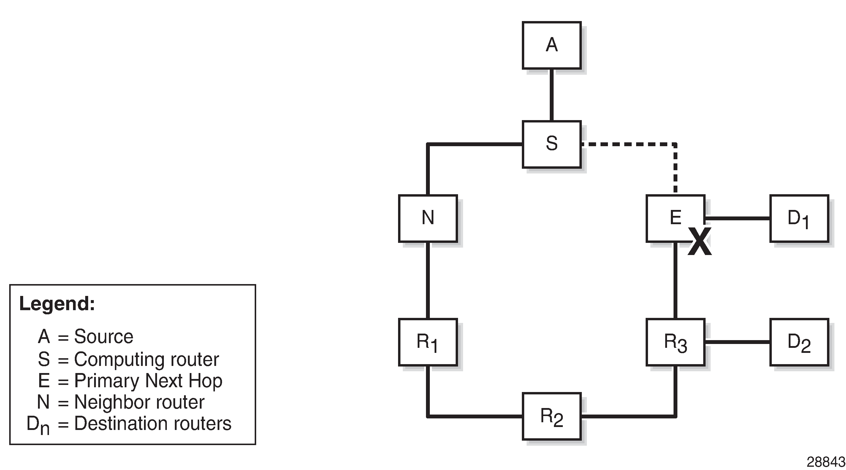
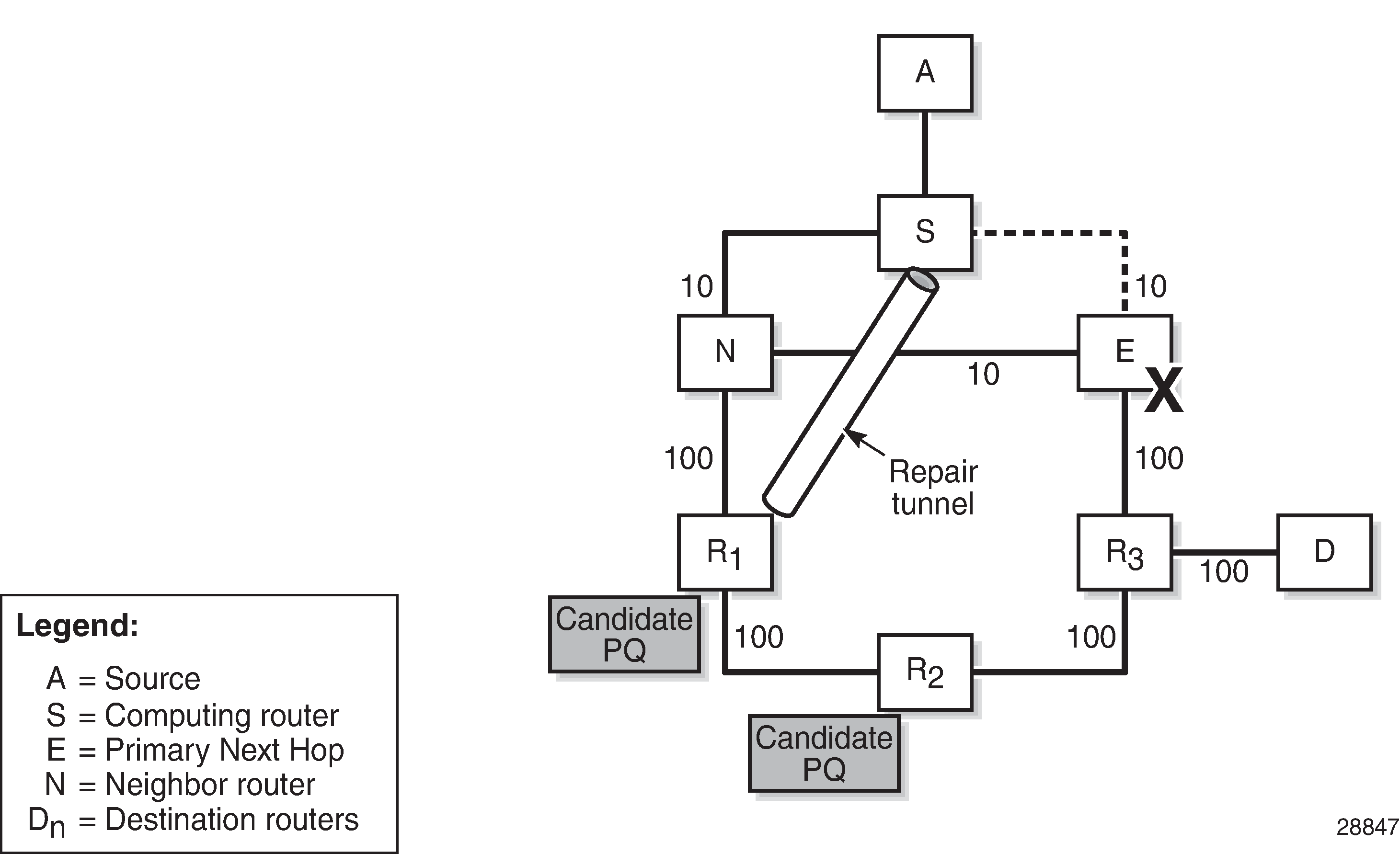
RFC 8102, Remote LFA node protection, defines the specifications to protect a path from a source A to a destination D1 or D2, when the primary next hop router E of a computing router S fails; see LFA node protection - topology & denominations. The R-LFA alternate path through a given PQ node to a given destination comprises two path segments:
path segment from the computing router S to the PQ node (R-LFA alternate next hop)
path segment from the PQ node to the destination D1 or D2
To ensure that an R-LFA alternate path next hop for a given destination provides node protection, none of the path segments may be affected in the event of a failure of the primary next-hop node E. The following four-step algorithm is used to satisfy this requirement:
Calculate the node protection extended P-space of router S with respect to the protected node E.
Calculate the link protection Q-space of router E with respect to the protected link SE.
Based on the results of step 1 and 2, a list of one or more candidate PQ-routers is compiled.
For each candidate PQ-router, perform an additional forward Shortest Path First (SPF) run to ensure that the path from the PQ-router to the destination router does not traverse the protected router E.
If more than one candidate PQ-router satisfies the condition from step 3, router S chooses the PQ-router based on criteria that are specified later in this chapter.
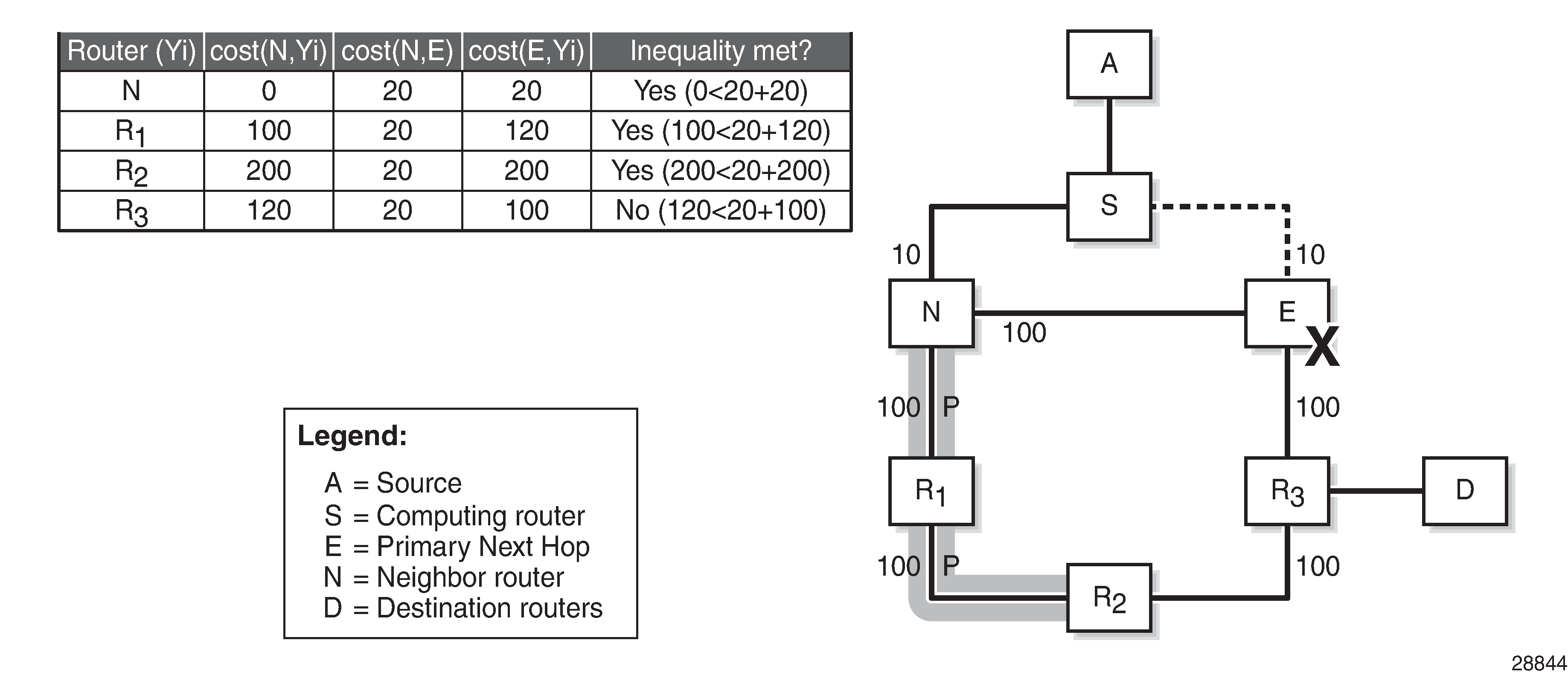
The node protection extended P-space is the set of routers Yi that are reachable from the direct neighbor(s) N of S without traversing protected router E. This excludes the direct neighbors for which there is at least one ECMP path from direct neighbor traversing router E. For a router Yi to be member of a node protection P-space, the following inequality must be true:
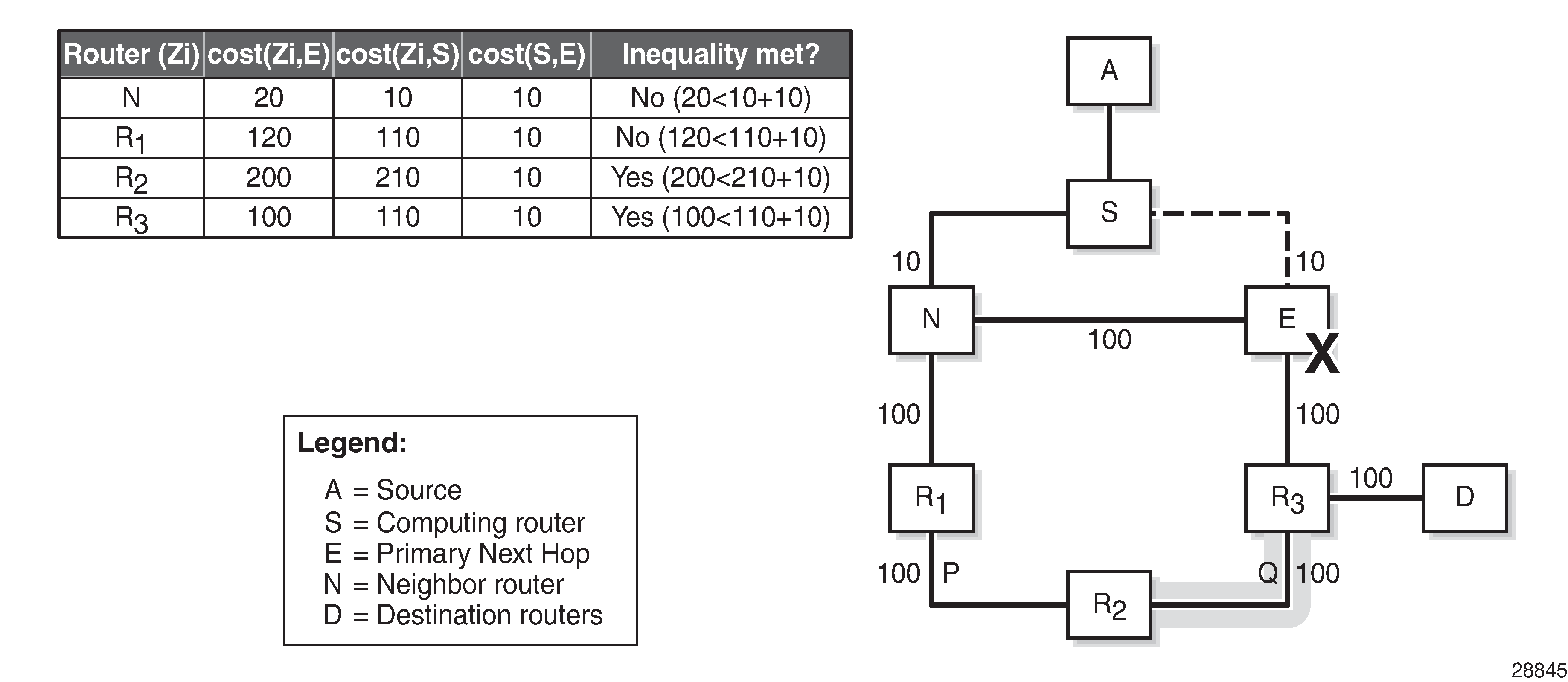
The link protection Q-space is the set of routers that can reach E without traversing the protected link SE, as defined in RFC 7490. This excludes equal cost path routes that traverse the SE link. For a router Yi to be member of the link protection Q-space, the following inequality must be true:
If, with respect to router E, a router Yi is present in the node protection extended P-space and present in the link protection Q-space, it is a candidate PQ node.
Node protecting extended P-space shows the example topology, with metrics and the calculations in table format to determine the node protection extended P-space of router S with respect to the protected node E. Only routers N, R1, and R2 meet the inequality, and therefore belong to the node protecting extended P-space.
Link protecting Q-space shows the example topology, with metrics and the calculations in table format to determine the link protecting Q-space of router E with respect to the protected link SE. Only routers R2 and R3 meet the inequality, and therefore belong to the link protecting Q-space.
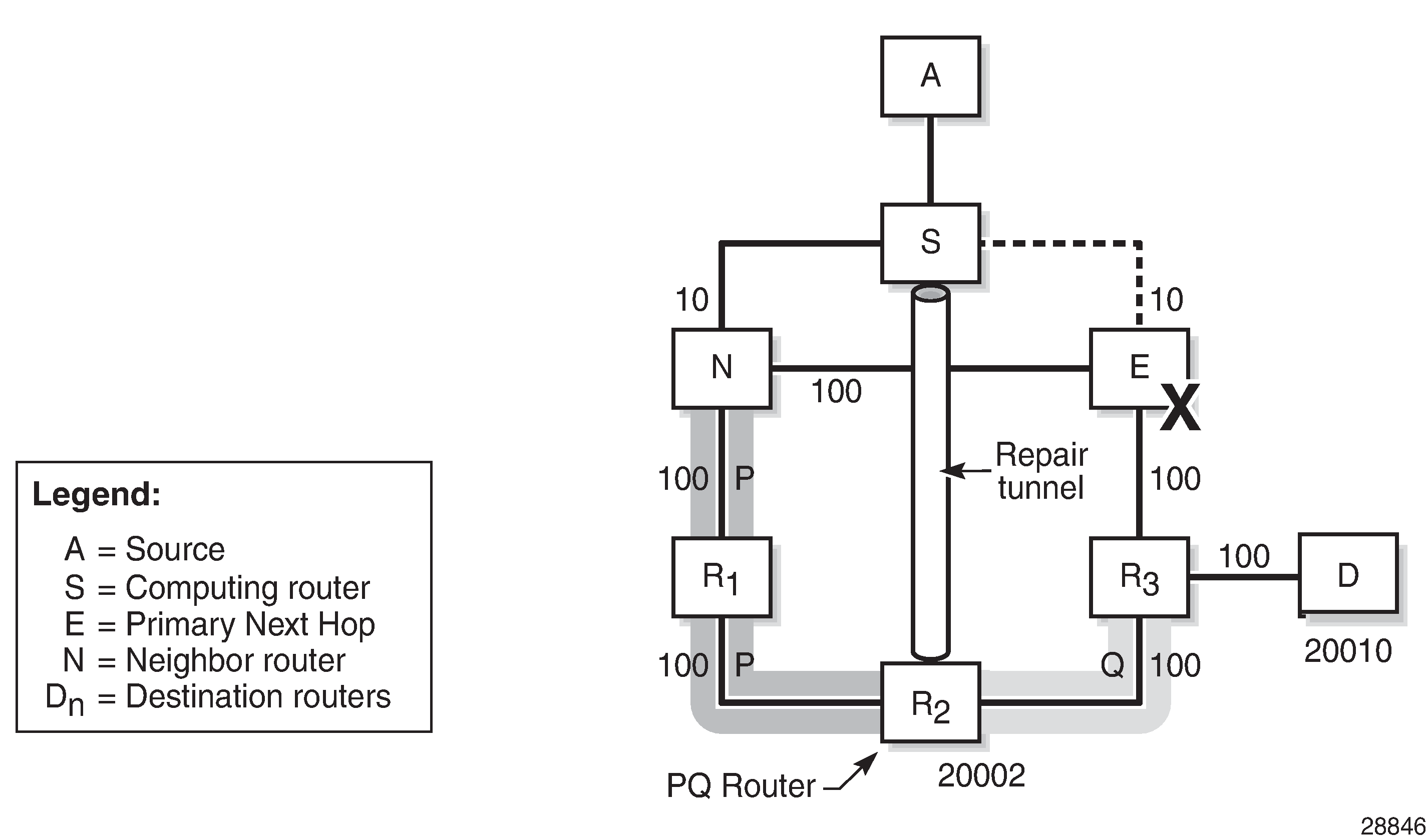
Candidate PQ routers are routers that belong to the extended P-space and the Q-space. In this example, only R2 is a candidate PQ node; see One candidate PQ-router – repair tunnel.
An additional forward SPF run is required to check that the shortest path from the candidate PQ node R2 toward destination D does not traverse protected node E. Therefore, the following inequality must be met:
Applied to this topology, the R2-R3-D path does not go via E; therefore, R2 is a valid R-LFA node protection PQ node. The previous inequality evaluates to true, as follows:
One candidate PQ-router – repair tunnel shows that S constructs a repair tunnel to PQ router R2. To reach destination D from S using the repair tunnel, S pushes a (20002, 20010) label stack, where 20002 and 20010 represent the node SIDs for R2 and D, respectively, while additionally setting the next-hop address to router N. The label 20002 is the first and top label swapped at N and R1, and popped at R2, while 20010 is the second label pushed at R2, swapped at R3, and ultimately popped at D.
In case multiple candidate PQ routers are available, the computing node S selects a PQ router based on the following criteria:
lowest IGP path cost from S
if multiple PQ routers satisfy (1), S selects the PQ router reachable via the neighbor with the lowest system-ID or router-ID for IS-IS and OSPF, respectively
if multiple PQ routers satisfy (1) and (2), S selects the PQ router with the lowest system-ID or router-ID for IS-IS and OSPF, respectively
Two candidate PQ routers – repair tunnel shows an example, with reduced metric between N and E, where R1 and R2 are the candidate PQ routers for protecting router E. In this example, R1 is chosen as the PQ router, because R1 is closer to S than R2. Router S will create an R-LFA repair tunnel for prefixes downstream of R3. To reach those prefixes, the R1 node SID and the D node SID are pushed, with N as the next hop. Prefixes downstream of N, R1, and R2 are unaffected by a failure of E, so they keep using N as their primary next-hop.
LFA and remote LFA interaction
The LFA and remote LFA CLI commands are applied in the OSPF and IS-IS router contexts, as follows:
configure
    router Base
        isis 0
            loopfree-alternates
                remote-lfa
                    node-protect
                exit
            exit
configure
    router Base
        ospf 0
            loopfree-alternates
                remote-lfa
                    node-protect
                exit
            exit
Regular LFA is enabled through the loopfree-alternates command. Additionally, the remote-lfa and remote-lfa node-protect command can be configured. In other words, by enabling remote LFA, regular LFA is also enabled.
A remote LFA repair tunnel is only calculated and created if no regular LFA backup next-hop exists. If this is a concern, Topology Independent LFA (TI-LFA) should be enabled; see the Topology-Independent Loop-Free Alternate for Link Protection chapter.
The LFA SPF algorithms are run using the following sequence:
A regular LFA is computed for each router and prefix, to provide a backup next-hop per prefix.
TI-LFA is computed for all routers and prefixes regardless of the outcome of step 1, and the TI-LFA computed next-hops override the regular LFA next-hops, if TI-LFA is enabled.
Remote LFA SPF is only run for the prefixes that are not protected after steps 1 and 2.
As a result, remote LFA next-hops, whether link or node protecting, are only computed and installed when no regular LFA next-hops are available for a given next-hop failure, assuming that TI-LFA is not configured. When the remote-lfa node-protect command is enabled, the router will prefer a node protect over a link-protect repair tunnel for a given prefix if both are found in the Remote LFA SPF computations.
Configuration
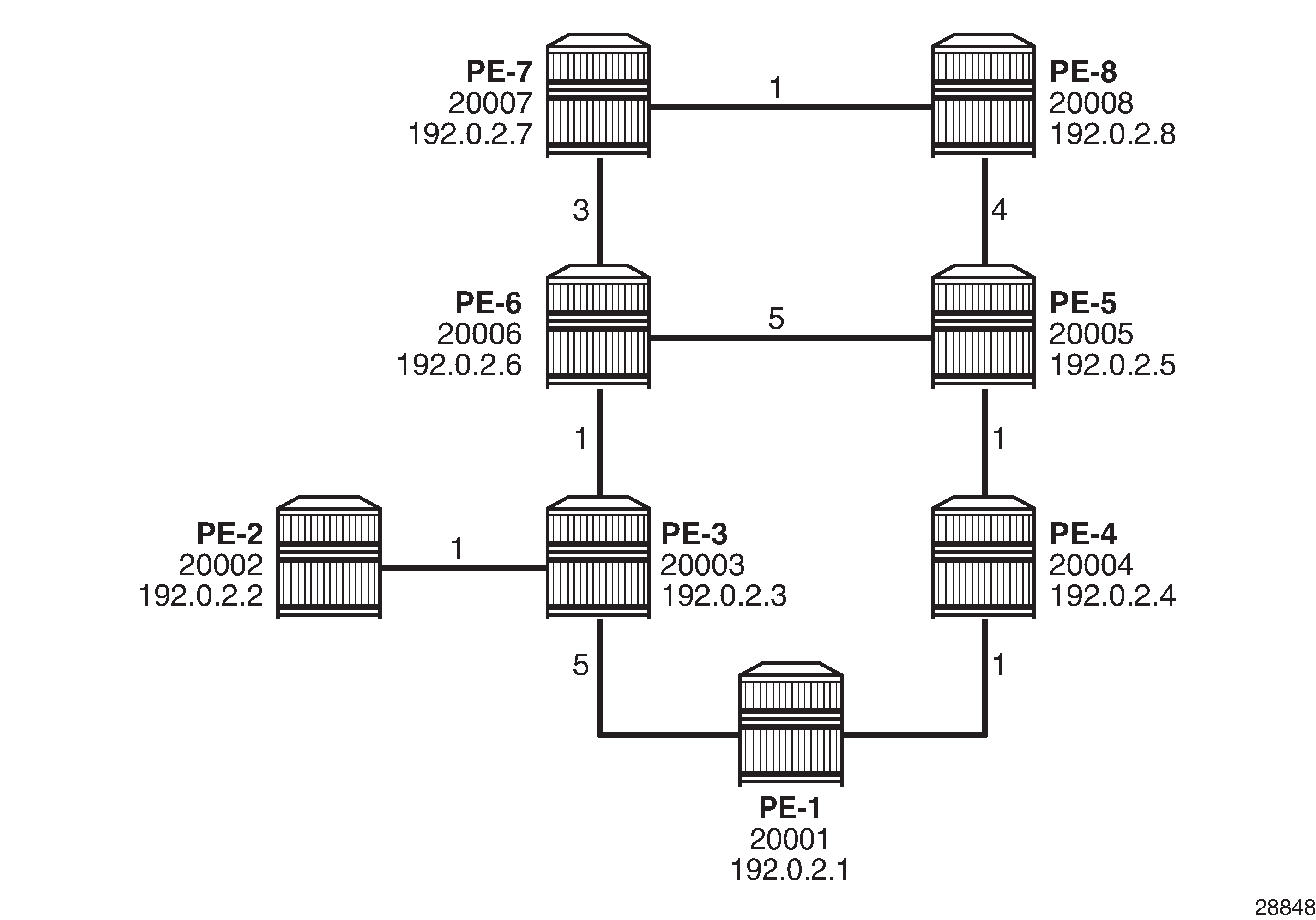
Three steps demonstrate the relationship between regular LFA and remote LFA, based on the example topology shown in Example topology. The traffic flow is going from PE-7 to PE-2, and a failure of PE-6 is simulated so that PE-7 is the computing router S, PE-2 is the destination router D, PE-6 is the failing primary next hop E, and PE-8 is the primary backup neighbor N.
The following scenarios are described:
enable regular LFA on PE-7 — node or link protection cannot be provided for prefixes downstream to PE-6
enable remote LFA link protection on PE-7 — define the repair tunnel
enable remote LFA node protection on PE-7 — define the repair tunnel
The configuration includes the following:
Cards, MDAs, ports
Single stack router interfaces (IPv4 only)
IS-IS as IGP on the router interfaces. The metrics shown in Example topology are used.
Segment routing (SR-ISIS) with node SIDs 2000x
The system addresses and the node SIDs for all routers are also shown in Example topology.
Regular LFA
The Segment Routing Global Block (SRGB) is defined consistently across all nodes in the network, as follows:
# on all nodes:
configure
    router Base
        mpls-labels
            sr-labels start 20000 end 20099
        exit
    exit
exit
The IS-IS configuration on PE-7 is as follows, and has regular LFA enabled:
# on PE-7:
configure
    router Base
        mpls-labels
            sr-labels start 20000 end 20099
        exit
        isis 0
            level-capability level-2
            area-id 49.0001
            traffic-engineering
            advertise-router-capability area
            loopfree-alternates
            exit
            segment-routing
                prefix-sid-range global
                no shutdown
            exit
            interface "system"
                ipv4-node-sid index 7
                no shutdown
            exit
            interface "int-PE-7-PE-6"
                interface-type point-to-point
                level 2
                    metric 3
                exit
                no shutdown
            exit
            interface "int-PE-7-PE-8"
                interface-type point-to-point
                level 2
                    metric 1
                exit
                no shutdown
            exit
            no shutdown
        exit
    exit
exit
PE-7 calculates the regular LFA node protection for prefixes downstream of PE-6. The shortest path from the primary backup neighbor PE-8 to router PE-2 must be less than the shortest path from the backup neighbor PE-8 node via PE-6, so the inequality becomes:
PE-7 calculates the regular LFA link protection for the PE-6-PE-7 link for prefixes downstream of PE-6. The shortest path from the primary backup neighbor PE-8 to router PE-2, must be less than the shortest path from the backup neighbor PE-8 via PE-7, so the inequality becomes:
Because both inequalities are false, PE-7 cannot provide regular LFA PE-6 node protection or regular LFA PE-6-PE-7 link protection.
Remote LFA with link protection
On PE-7, LFA is reconfigured so that remote LFA with link protection applies, as follows:
# on PE-7:
configure
    router Base
        isis 0
            loopfree-alternates
                remote-lfa
                exit
            exit
        exit
    exit
exit
A repair tunnel will be established, avoiding and protecting the PE-6-PE-7 link, where the endpoint of the repair tunnel is situated on a PQ router.
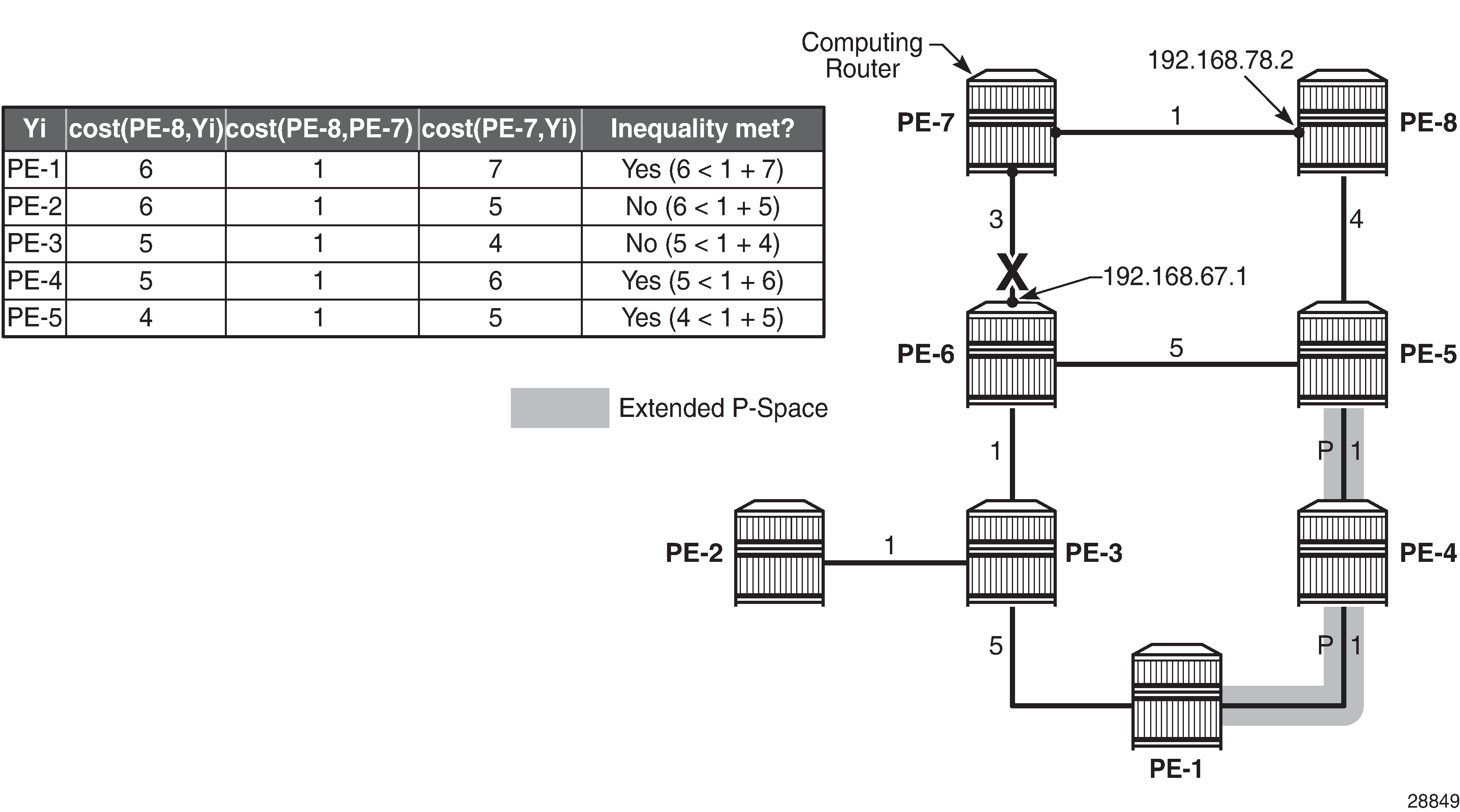
Link protection extended P-space calculation provides the calculations in table format, along with a graphical representation, to determine the link protecting extended P-space of router PE-7 with respect to the protected PE-6-PE-7 link. Routers PE-1, PE-4, and PE-5 meet the inequality, and therefore belong to the link protecting extended P-space, meaning that they can be reached from backup neighbor PE-8 using an SPF path excluding the PE-6-PE-7 link.
Link protecting Q-space calculation provides the calculations in table format, along with a graphical representation, to determine the link protecting Q-space of router PE-6 with respect to protected PE-7-PE-6 link. Routers PE-1, PE-2, PE-3, PE-4, and PE-5 meet the inequality, and therefore belong to the link protecting Q-space.

Repair tunnel shows that PE-1, PE-4, and PE-5 are the candidate PQ routers. PE-5 is chosen as the repair tunnel endpoint because of the lowest path cost toward computing node PE-7 (IGP cost from PE-7 to PE-5 = 5). The closest PQ router is chosen to maximize the opportunity for load sharing traffic between the repair tunnel endpoint and the destination router.
On the computing node PE-7, the tunnel table for PE-2 destination (192.0.2.2) on IOM 1 shows that 192.168.67.1 is the next hop for the primary path, and that 192.168.78.2 is the next hop for the backup path, as follows. In the normal situation, the PE-7 to PE-2 traffic is routed along the PE-7-PE-6-PE-3-PE-2 path. In case of a PE-7-PE-6 link failure, the traffic on PE-7 node is pushed out with labels 20002 and 20005 to PE-8 (192.168.78.2). The top label is 20005, representing the node SID for PE-5, and 20002 is the label representing the node SID for PE-2.
Traffic destined for PE-2 and arriving at PE-5 with label 20005 will take the shortest path to PE-2 and therefore will traverse node PE-6.
*A:PE-7# show router fp-tunnel-table 1 192.0.2.2/32

===============================================================================
IPv4 Tunnel Table Display

Legend:
label stack is ordered from bottom-most to top-most
B - FRR Backup
===============================================================================
Destination                                  Protocol            Tunnel-ID
  Lbl
    NextHop                                                      Intf/Tunnel
  Lbl     (backup)
    NextHop   (backup)
-------------------------------------------------------------------------------
192.0.2.2/32                                 SR-ISIS-0            524292
  20002
    192.168.67.1                                                  1/1/2
  20002/20005
    192.168.78.2(B)                                               1/1/1
-------------------------------------------------------------------------------
Total Entries : 1
-------------------------------------------------------------------------------
===============================================================================
Similar information can be obtained with a tools dump command, as follows:
*A:PE-7# tools dump router segment-routing tunnel in-label 20002
===================================================================================================
Legend: (B) - Backup Next-hop for Fast Re-Route
        (D) - Duplicate
label stack is ordered from top-most to bottom-most
===================================================================================================
--------------------------------------------------------------------------------------------------+
 Prefix
 Sid-Type        Fwd-Type       In-Label  Prot-Inst(algoId)
                  Next Hop(s)                                     Out-Label(s) Interface
                                                                        /Tunnel-ID |
--------------------------------------------------------------------------------------------------+
 192.0.2.2
 Node            Orig/Transit   20002     ISIS-0
                 192.168.67.1                                    20002       int-PE-7-PE-6
(B)192.168.78.2                                    20005       int-PE-7-PE-8
20002
--------------------------------------------------------------------------------------------------+
No. of Entries: 1
--------------------------------------------------------------------------------------------------+
Another tools command indicates the used LFA type through flags, as follows. Only RLFA link protection applies, and not node protection.
*A:PE-7# tools dump router isis sr-database prefix 192.0.2.2 sid 2
===============================================================================
Rtr Base ISIS Instance 0 SR Database
===============================================================================
SID   Label  Prefix          Last-act  Lev MT RtmPref TtmPref Metric  IpNh SrNh
  Mtu    MtuPrim MtuBk  D xL LT Act AdvSystemId    SrErr
-------------------------------------------------------------------------------
2     20002  192.0.2.2       LfaNhops  2   0  18      11      5       1    1
  1556   1564    1564   0 0  R  +R  1920.0000.2002 SR_ERR_OK

-------------------------------------------------------------------------------
No. of Entries: 1
-------------------------------------------------------------------------------
Lev = route level
IpNh = number of IP next-hops
SrNh = number of SR-tunnel next-hops
D = duplicate pending
xL = exclude from LFA
LT = LFA type (L:LFA, R:RLFA, T:TILFA, n:nodeProtection)
Act = tunnel active state (R:reported, F:failed, +:SR-ack)
===============================================================================
Remote LFA with node protection
On PE-7, LFA is reconfigured so that remote LFA with node protection applies, as follows:
# on PE-7:
configure
    router Base
        isis 0
            loopfree-alternates
                remote-lfa
                    node-protect
                exit
            exit
        exit
    exit
exit
The general node protecting inequality from the Overview section must be used for defining the node protecting extended P-space. Using the topology from Example topology, the inequality becomes:
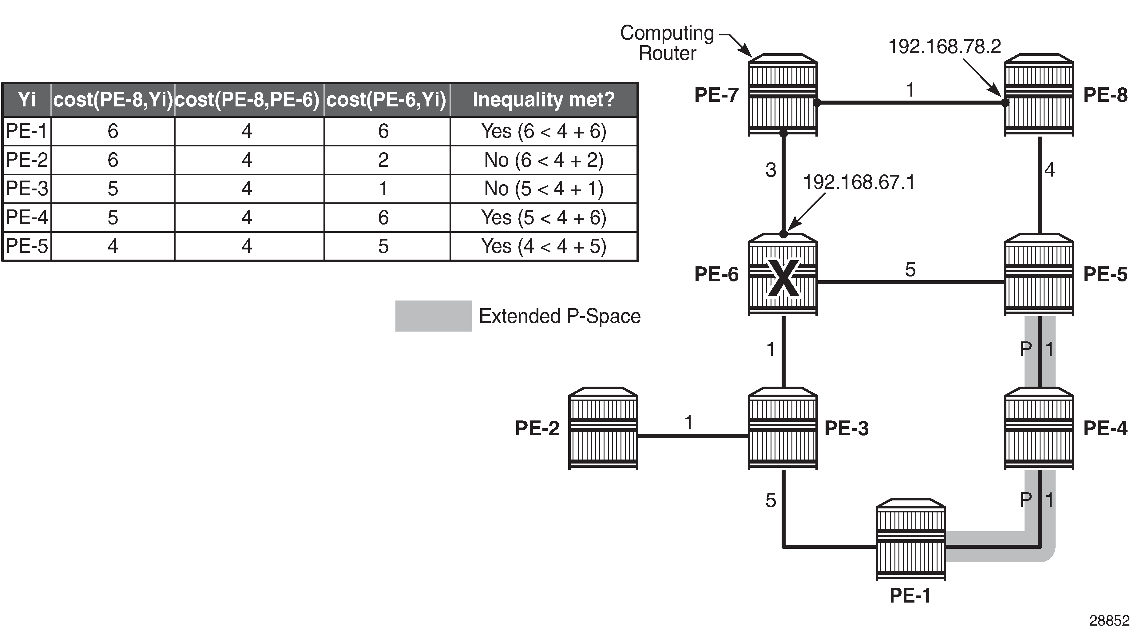
Node protecting extended P-space calculation provides the calculations in table format, along with a graphical representation, to determine the node protecting extended P-space of router PE-7 with respect to protected PE-6 node. Routers PE-1, PE-4, and PE-5 meet the inequality, and therefore belong to the node protecting extended P-space, meaning that they can be reached from backup neighbor PE-8 through an SPF path not passing through node PE-6.
The general link protecting inequality from the overview section must be used for defining the Q-space. Using the topology from Example topology, the inequality becomes:
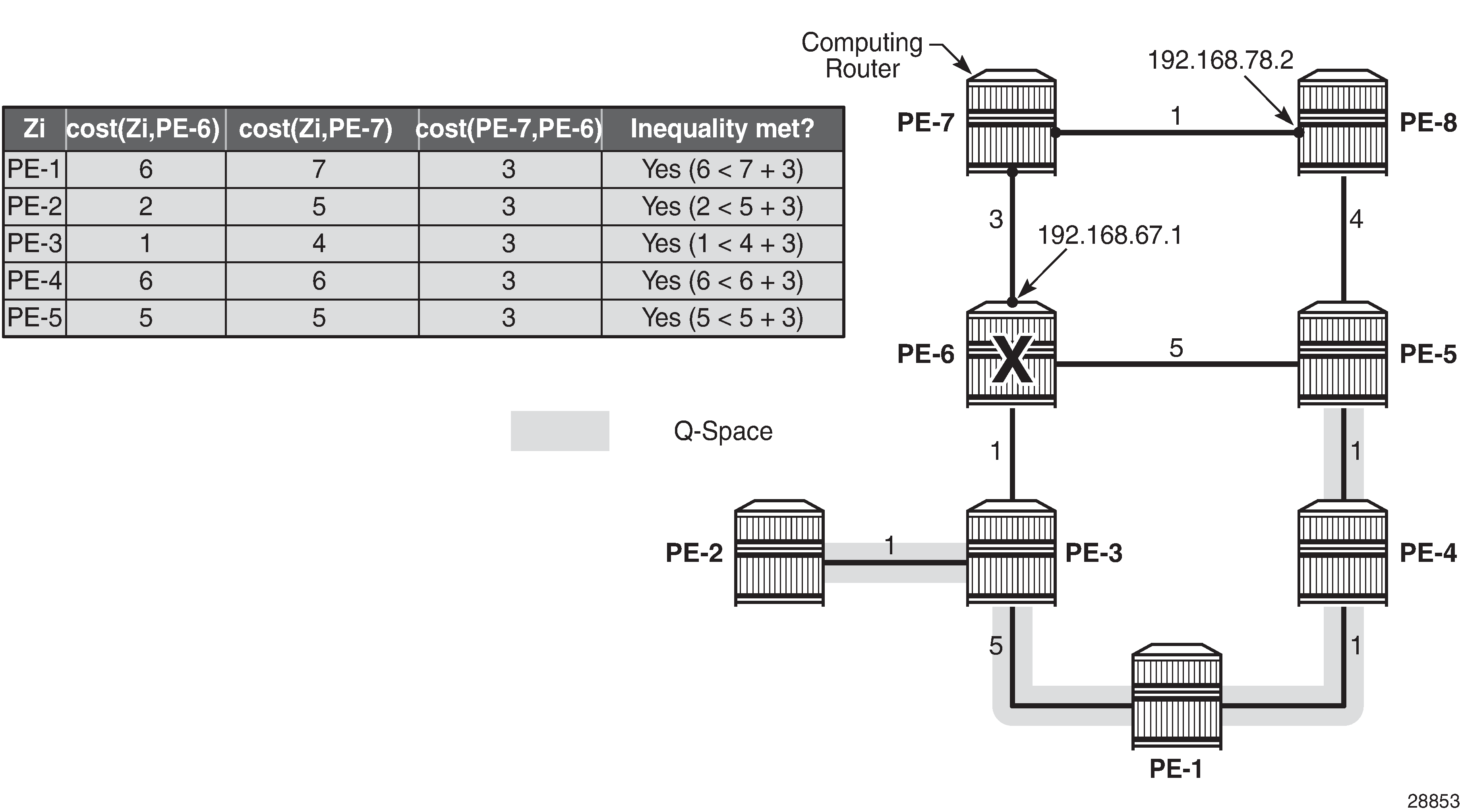
Link protecting Q-space calculation provides the calculations in table format, along with a graphical representation, to determine the link protecting Q-space of router PE-6 with respect to the protected PE-7-PE-6 link. Routers PE-1, PE-2, PE-3, PE-4, and PE-5 meet the inequality, and therefore belong to the link protecting Q-space.
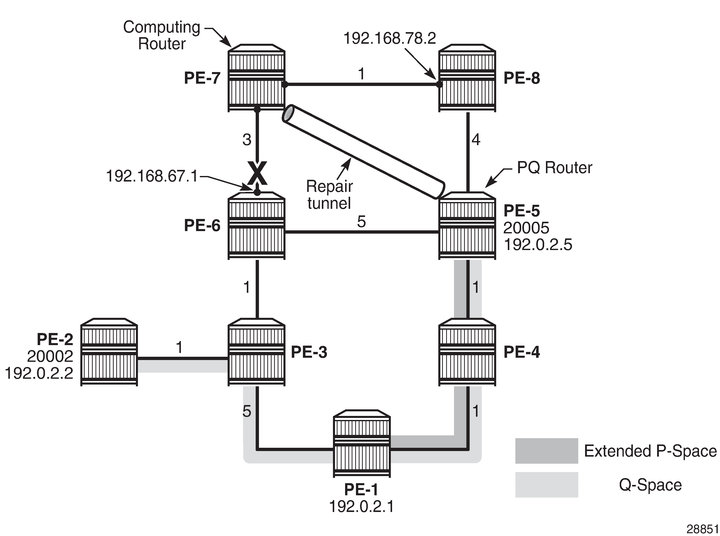
Validating candidate PQ routers - repair tunnel calculation shows that PE-1, PE-4, and PE-5 are the candidate PQ routers for protecting router PE-6. An additional forward SPF run is required for every candidate PQ router, to ensure that the shortest path from that candidate PQ router to destination PE-2 does not traverse the protected router PE-6. The general formula from the Overview section becomes:
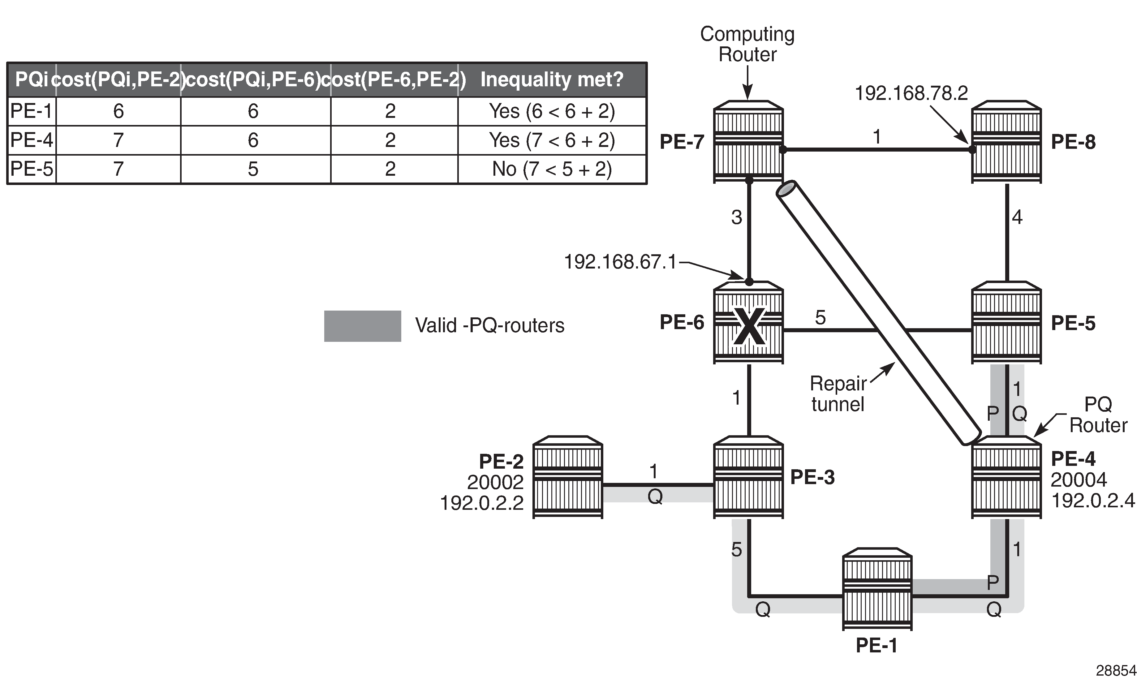
After validating all three candidate PQ routers, only routers PE-1 and PE-4 are valid for terminating a repair tunnel. The tie-breaker for defining the repair tunnel termination is the lowest IGP path cost from the computing node PE-7 point of view. The cost from PE-7 to PE-4 is lower than the cost from PE-7 to PE-1 (6 < 7), so PE-4 becomes the PQ router.
The tunnel table for destination 192.0.2.2 on IOM 1 shows that 192.168.67.1 is the next hop for the primary path, and that 192.168.78.2 is the next hop for the backup path, as follows. In the normal situation, the PE-7 to PE-2 traffic is routed along the PE-7-PE-6-PE-3-PE-2 path. In case of a PE-6 node failure, the traffic from PE-7 is pushed out to PE-8 (192.168.78.2), with two labels. The label 20004 represents the node SID for PQ node PE-4 and is used as the top (first) label, while 20002 represents the node SID for PE-2 and is used as the second label.
*A:PE-7# show router fp-tunnel-table 1 192.0.2.2/32

===============================================================================
IPv4 Tunnel Table Display

Legend:
label stack is ordered from bottom-most to top-most
B - FRR Backup
===============================================================================
Destination                                  Protocol            Tunnel-ID
  Lbl
    NextHop                                                      Intf/Tunnel
  Lbl     (backup)
    NextHop   (backup)
-------------------------------------------------------------------------------
192.0.2.2/32                                 SR-ISIS-0            524292
  20002
    192.168.67.1                                                  1/1/2
  20002/20004
    192.168.78.2(B)                                               1/1/1
-------------------------------------------------------------------------------
Total Entries : 1
-------------------------------------------------------------------------------
===============================================================================
Similar information can be obtained with a tools dump command, as follows:
*A:PE-7# tools dump router segment-routing tunnel in-label 20002

===================================================================================================
Legend: (B) - Backup Next-hop for Fast Re-Route
        (D) - Duplicate
label stack is ordered from top-most to bottom-most
===================================================================================================
--------------------------------------------------------------------------------------------------+
 Prefix                                                                                           |
 Sid-Type        Fwd-Type       In-Label  Prot-Inst(algoId)                                      |
               Next Hop(s)                                     Out-Label(s) Interface
                                                                         Tunnel-ID |
--------------------------------------------------------------------------------------------------+
 192.0.2.2
 Node            Orig/Transit   20002     ISIS-0
                 192.168.67.1                                    20002       int-PE-7-PE-6
(B)192.168.78.2                                    20004       int-PE-7-PE-8
20002
--------------------------------------------------------------------------------------------------+
No. of Entries: 1
--------------------------------------------------------------------------------------------------+
Another tools command indicates the used LFA type through flags, as follows. RLFA and node protection applies.
*A:PE-7# tools dump router isis sr-database prefix 192.0.2.2 sid 2
===============================================================================
Rtr Base ISIS Instance 0 SR Database
===============================================================================
SID   Label  Prefix          Last-act  Lev MT RtmPref TtmPref Metric  IpNh SrNh
  Mtu    MtuPrim MtuBk  D xL LT Act AdvSystemId    SrErr
-------------------------------------------------------------------------------
2     20002  192.0.2.2       LfaNhops  2   0  18      11      5       1    1
  1556   1564    1564   0 0  Rn +R  1920.0000.2002 SR_ERR_OK

-------------------------------------------------------------------------------
No. of Entries: 1
-------------------------------------------------------------------------------
Lev = route level
IpNh = number of IP next-hops
SrNh = number of SR-tunnel next-hops
D = duplicate pending
xL = exclude from LFA
LT = LFA type (L:LFA, R:RLFA, T:TILFA, n:nodeProtection)
Act = tunnel active state (R:reported, F:failed, +:SR-ack)
===============================================================================
The LFA coverage is as follows:
*A:PE-7# show router isis sr-lfa-coverage

===============================================================================
Rtr Base ISIS Instance 0 SR LFA Coverage
===============================================================================
MT-ID   SidType      Level Proto LFA       RLFA      TILFA     Coverage
-------------------------------------------------------------------------------
0       node-sid     L2    ipv4  3(42%)    4(57%)    0(0%)     7/7(100%)
0       adj-sid      L2    ipv4  0(0%)     2(100%)   0(0%)     2/2(100%)
===============================================================================
Conclusion
Remote LFA Node Protection provides operators the means to create resilient networks, with precalculated backup paths and with improved coverage.