Topology-Independent Loop-Free Alternate for Link Protection
This chapter describes the Topology-Independent Loop-Free Alternate for Link Protection.
Topics in this chapter include:
Applicability
This chapter was initially written based on SR OS Release 16.0.R5, but the CLI in the current edition corresponds to SR OS Release 21.2.R1. Topology-Independent Loop-Free Alternate (TI-LFA) is supported from SR OS Release 15.0.R1 for IS-IS and 15.0.R4 for OSPF.
Overview
For IP Fast Reroute (FRR), the routers use a precomputed Loop-Free Alternate (LFA) next-hop installed in the FIB until the Shortest Path First (SPF) algorithm runs and the network converges again. The following LFA modes can be applied:
Regular LFA installs an alternate next-hop in the FIB. Regular LFA provides protection for native IP traffic as well as for Segment Routing (SR) and LDP traffic.
Remote LFA uses a repair tunnel to a PQ node, which is a node where traffic is not looped back toward the computing node. Remote LFA provides protection for SR and LDP traffic, not for native IP traffic.
If a computing router has multiple backup next-hop routers, TI-LFA creates a repair tunnel on the post-convergence path so that the post-failure next-hop is avoided, if different from the post-convergence next-hop. In this case, traffic will not be dropped after SPF converges. TI-LFA extends the remote LFA algorithm by computing a backup tunnel where the P and Q nodes do not coincide. TI-LFA uses a repair tunnel to the closest Q node on the post-convergence path. This repair tunnel uses the shortest path to the P node and a source-routed path from the P node to the Q node. TI-LFA provides protection for SR and LDP traffic, not for native IP traffic.
Regular LFA is described in chapter MPLS LDP FRR using ISIS as IGP. Remote LFA and TI-LFA use segment routing to create repair tunnels in cases where there is no regular LFA backup.
Post-failure LFA path does not match post-convergence path shows the example topology where traffic flows from CE-40 toward CE-50, and a post-failure LFA path that does not match the post-convergence path.
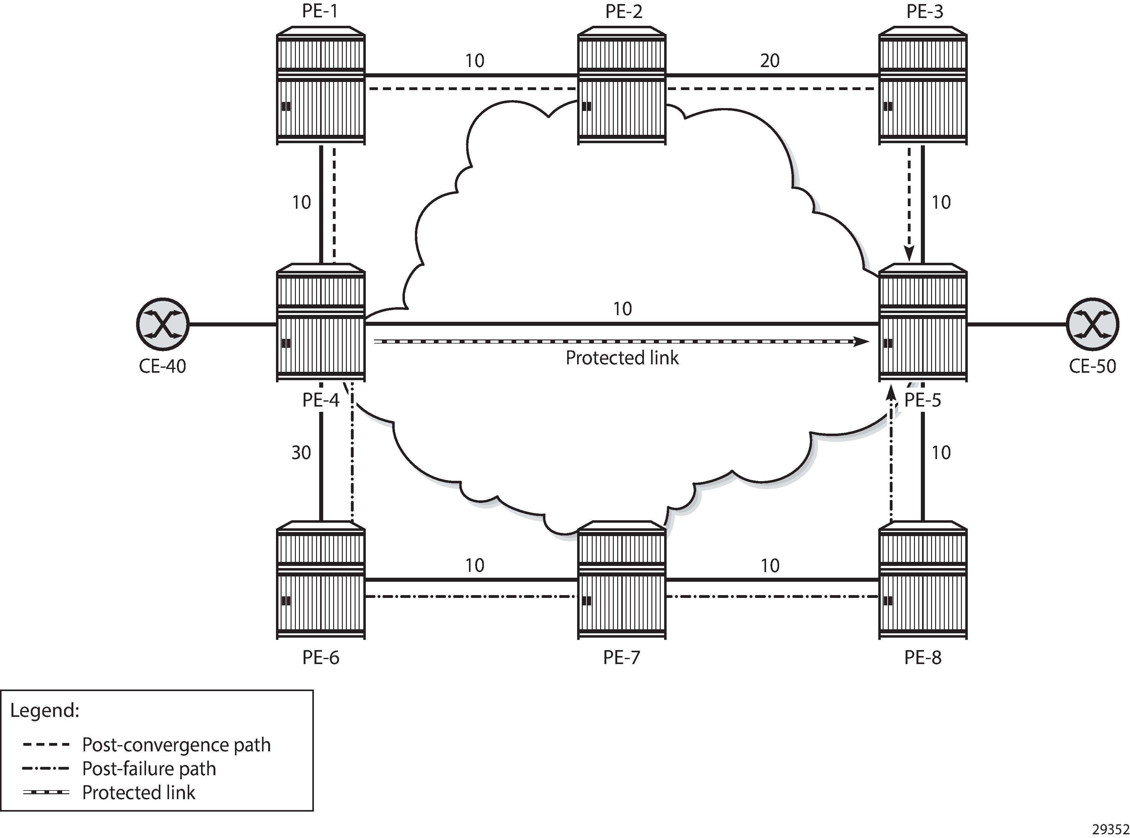
During normal operation, traffic goes from CE-40 to PE-4 and straight on to PE-5 and CE-50. This is the shortest path between CE-40 and CE-50. Consider the failure of the link between PE-4 and PE-5. This is the protected link. If a failure occurs on the protected link between PE-4 and PE-5, there are two possible backup next-hops from computing node PE-4: PE-1 or PE-6.
When enabling regular LFA on PE-4, two consecutive failovers will occur: the first one, nearly instantaneously, from the preferred path (optimum distance) to the precomputed post-failure path via next-hop PE-6 and the second one, after SPF has run again, from the post-failure path to the post-convergence path via PE-1. When enabling TI-LFA, a single failover will occur, so the computed post-failure path must match the post-convergence path.
The post-convergence path will be from PE-4 to PE-1, PE-2, PE-3, and PE-5, with a path cost of 10 + 10 + 20 + 10 = 50. With regular LFA, the post-failure path should not use PE-1 as next-hop, because PE-1 would loop back traffic to reach PE-5 via PE-4, through the protected link (which is not allowed).
As described in RFC 5286, the following inequality 1 for link protection must be true for a neighbor next-hop (NH) to provide an LFA. The cost is the optimum distance between the nodes:
For next-hop PE-1, the following LFA inequality 1 is false on the calculating node PE-4, indicating that no regular LFA path is possible via PE-1:
For next-hop PE-6, the following LFA inequality 1 is true on the calculating node PE-4, indicating that a regular LFA path is possible via PE-6:
Because of the higher metric between PE-4 and PE-6 (30), PE-6 will not loop back traffic via PE-4: the path cost from PE-6 to PE-5 via PE-4 = 30 + 10 = 40, while the path cost from PE-6 to PE-5 via PE-7 and PE-8 = 10 + 10 + 10 = 30. So, PE-6 will forward the traffic to PE-7, PE-8, and PE-5.
For these reasons, the post-failure path uses PE-6 as regular LFA next-hop.
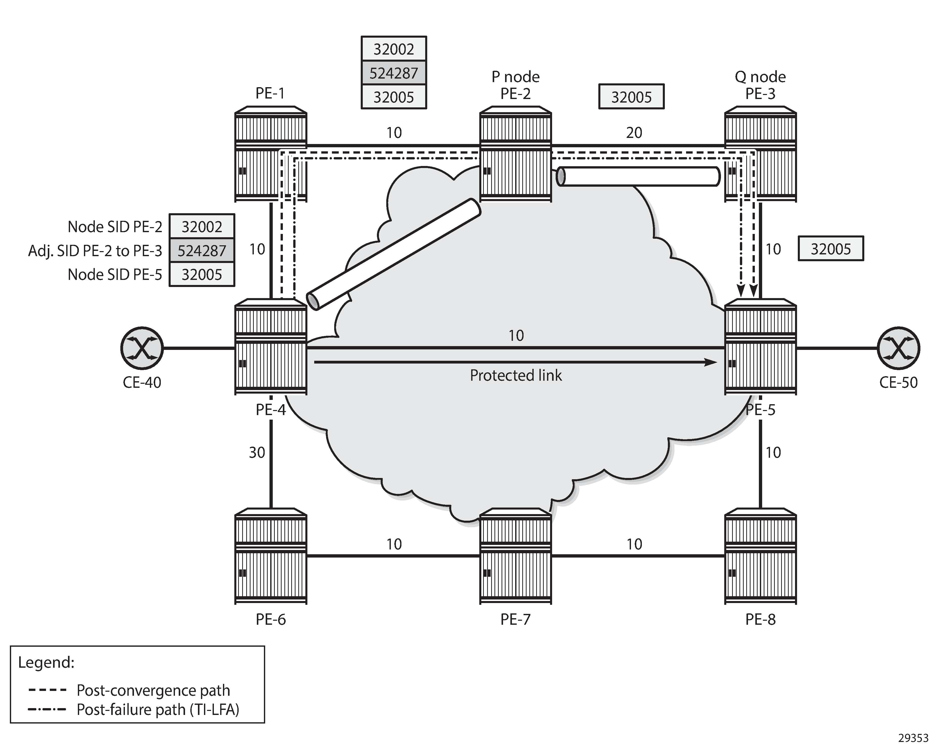
TI-LFA ensures that traffic is forwarded in a tunnel to the closest Q node, where it will not be looped back to PE-4. In this example. PE-3 is the Q node and it is one hop away from P node PE-2.
With TI-LFA enabled, additional labels are pushed to ensure that the post-failure next-hop matches the post-convergence next-hop. When the protected link between PE-4 and PE-5 fails, PE-4 pushes the node SID of PE-2 as top label plus the adjacency SID of the PE-2 to PE-3 link as an extra label. The bottom label is the node SID of the destination PE-5, which is present in any packet to PE-5 (located on the primary path); see Post-failure TI-LFA path matches post-convergence path.
In this chapter, the following LFA modes are described and configured:
Regular LFA
Remote LFA
TI-LFA
Configuration
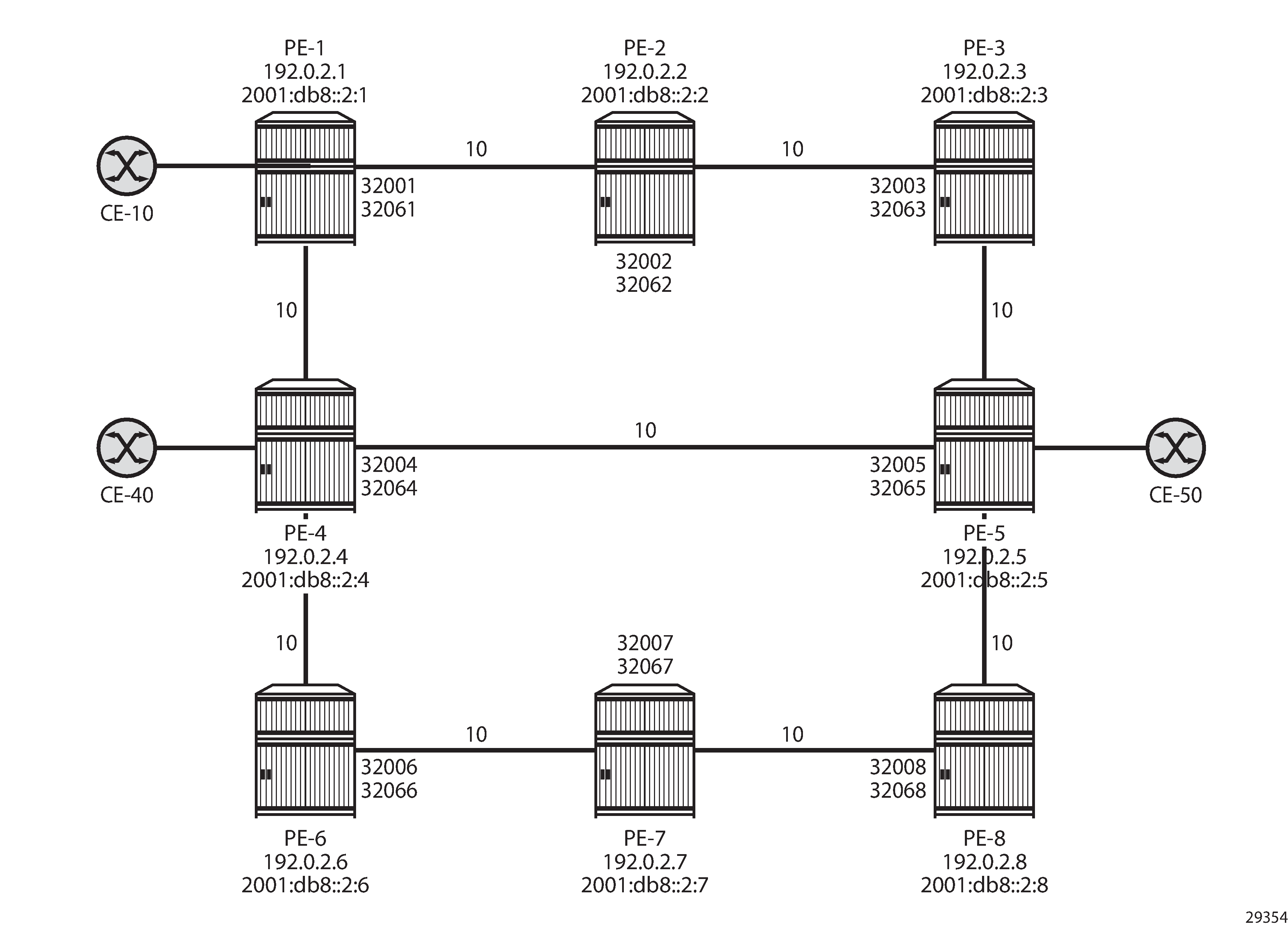
Example topology shows the example topology, but that will be reduced in the first two scenarios. The default metric of all links is 10, but that may be configured with a different value afterward.
The initial configuration includes the following:
Cards, MDAs, ports
Dual-stack router interfaces (IPv4/IPv6)
IS-IS as IGP on the router interfaces. The metric is 10, but that may be configured otherwise.
Segment routing (SR-ISIS) with node SIDs 3200x for IPv4 and 3206x for IPv6 system addresses.
Regular LFA
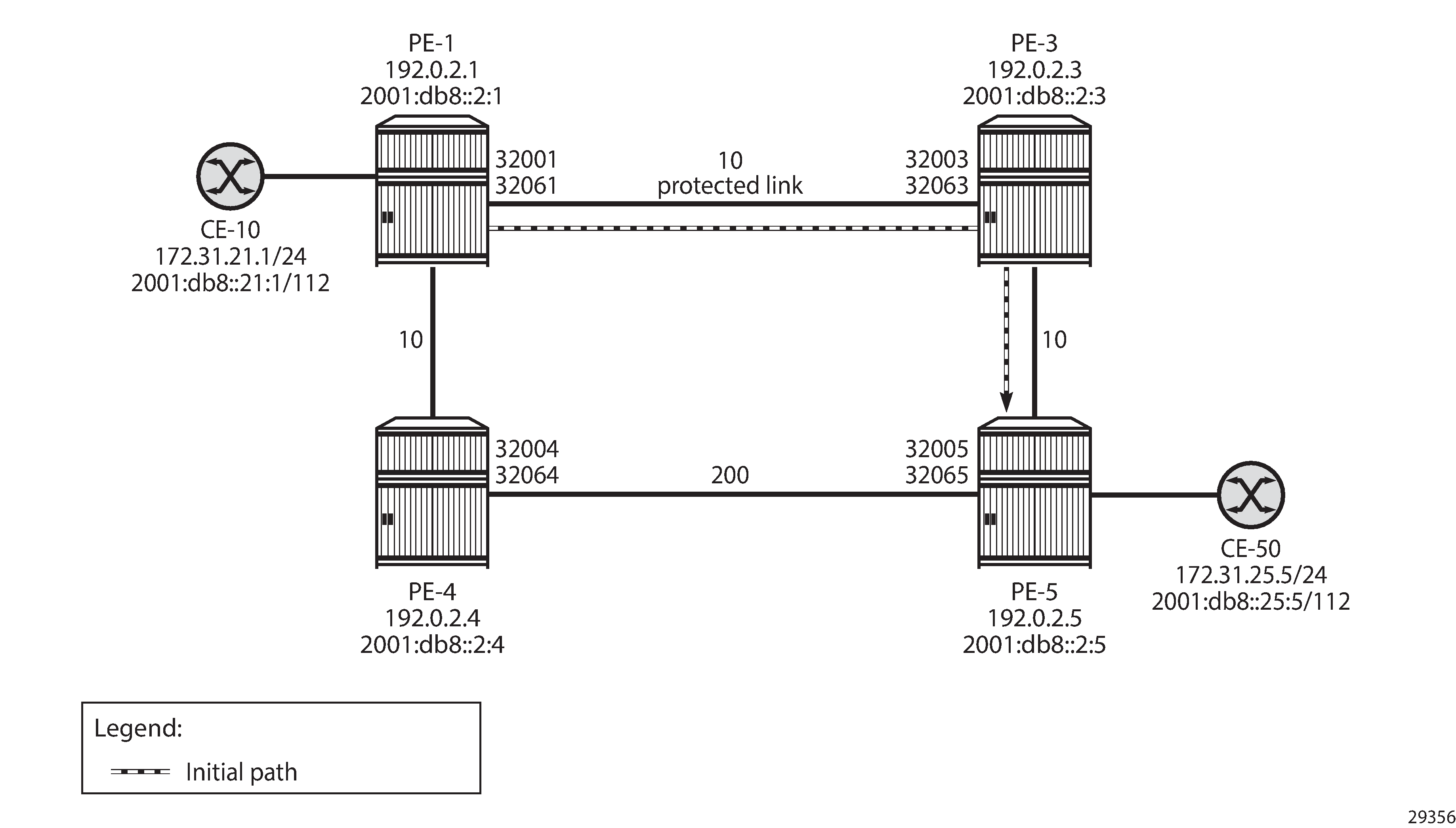
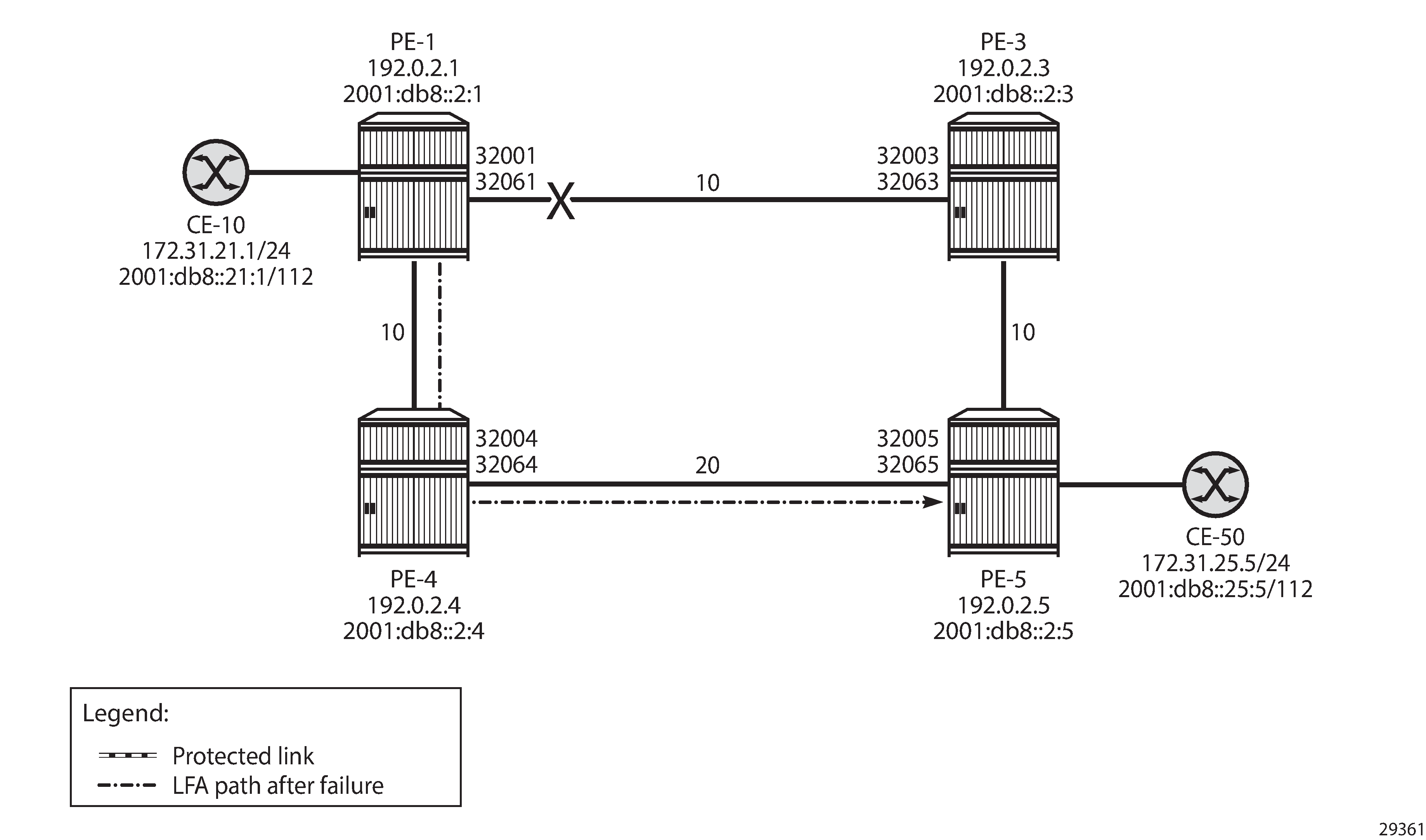
Example topology with regular LFA configured on PE-4 shows the example topology reduced to four PEs. Without a failure of the protected link, traffic from CE-10 to CE-50 is sent via PE-3. The protected link is the link between PE-1 and PE-3 and the LFA path after failure goes via next-hop PE-4.
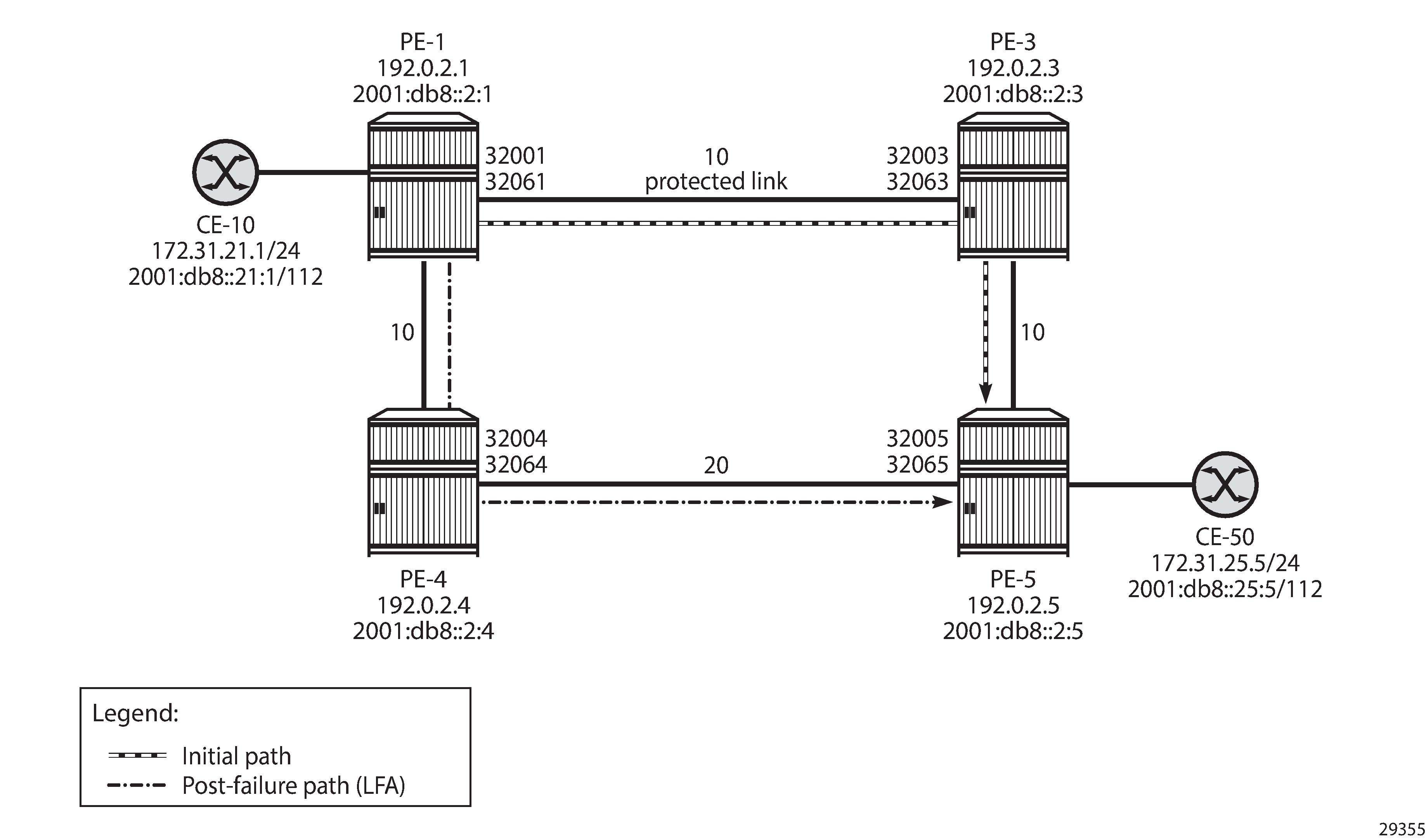
The IGP metric on the interface between PE-4 and PE-5 is 20, as follows:
# on PE-4:
configure
    router Base
        isis 0
            interface "int-PE-4-PE-5"
                level 1
                    metric 20
                exit
                level 2
                    metric 20
                exit
                no shutdown
            exit
#on PE-5:
configure
    router Base
        isis 0
            interface "int-PE-5-PE-4"
                level 1
                    metric 20
                exit
                level 2
                    metric 20
                exit
                no shutdown
            exit
Regular LFA is configured on the nodes, as follows:
# on PE-1, PE-3, PE-4, PE-5:
configure
    router Base
        isis 0
            loopfree-alternates
In the normal situation, without failures, the preferred traffic path from CE-10 to CE-50 is via PE-1, PE-3, and PE-5 with a cost (optimum distance) of 10 + 10 = 20. When the link between PE-1 and PE-3 fails, the post-failure LFA path is via PE-1, PE-4, and PE-5 with a cost of 10 + 20 = 30. The following LFA inequality 1 is true, so PE-4 is a valid LFA next-hop:
The route table on PE-1 for prefix 192.0.2.5 shows that the next-hop is 192.168.13.2 on PE-3 for the preferred path with metric 20; the LFA next-hop is 192.168.14.2 on PE-4 for the post-failure path with metric 30, as follows:
*A:PE-1# show router route-table 192.0.2.5 alternative

===============================================================================
Route Table (Router: Base)
===============================================================================
Dest Prefix[Flags]                            Type    Proto     Age        Pref
Next Hop[Interface Name]                                    Metric
Alt-NextHop                                                Alt-
Metric
-------------------------------------------------------------------------------
192.0.2.5/32                                  Remote  ISIS      00h11m58s  15
192.168.13.2                                                 20
192.168.14.2 (LFA)                                           30
-------------------------------------------------------------------------------
No. of Routes: 1
Flags: n = Number of times nexthop is repeated
       Backup = BGP backup route
LFA = Loop-Free Alternate nexthop
       S = Sticky ECMP requested
===============================================================================
The following FP tunnel table on PE-1 shows the SR-ISIS label 32005, which is the node SID of PE-5 for prefix 192.0.2.5/32. The same label 32005 is used for the LFA post-failure path indicated with (B) for FRR backup.
*A:PE-1# show router fp-tunnel-table 1 192.0.2.5/32

===============================================================================
IPv4 Tunnel Table Display

Legend:
label stack is ordered from bottom-most to top-most
B - FRR Backup
===============================================================================
Destination                                  Protocol            Tunnel-ID
   Lbl
    NextHop                                                      Intf/Tunnel
  Lbl     (backup)
    NextHop   (backup)
-------------------------------------------------------------------------------
192.0.2.5/32                                 SR-ISIS-0            524301
  32005
    192.168.13.2                                                  1/1/3:1000
  32005
    192.168.14.2(B)                                               1/1/2:1000
-------------------------------------------------------------------------------
Total Entries : 1
-------------------------------------------------------------------------------
===============================================================================
The following FP tunnel table on PE-1 shows the SR-ISIS label 32065, which is the node SID of PE-5 for prefix 2001:db8::2:5/128. The same label 32065 is used for the LFA post-failure path.
*A:PE-1# show router fp-tunnel-table 1 2001:db8::2:5/128

===============================================================================
IPv6 Tunnel Table Display

Legend:
label stack is ordered from bottom most to top-most
B - FRR Backup
===============================================================================
Destination                                  Protocol            Tunnel-ID
  Lbl
    NextHop                                                      Intf/Tunnel
  Lbl     (backup)
    NextHop   (backup)
-------------------------------------------------------------------------------
2001:db8::2:5/128                            SR-ISIS-0            524302
  32065
    fe80::618:1ff:fe01:3-"int-PE-1-PE-3"                          1/1/3:1000
  32065
    fe80::61c:1ff:fe01:1-"int-PE-1-PE-4"(B)                       1/1/2:1000
-------------------------------------------------------------------------------
Total Entries : 1
-------------------------------------------------------------------------------
===============================================================================
No post-failure LFA path when PE-4 loops back traffic shows that no backup LFA next-hop exists when the metric on the interface between PE-4 and PE-5 is increased to 200.
The following configures the metric on the interface between PE-4 and PE-5 to a value of 200:
# on PE-4:
configure
    router Base
        isis 0
            interface "int-PE-4-PE-5"
                level 1
                    metric 200
                exit
                level 2
                    metric 200
                exit
                no shutdown
            exit
# on PE-5:
configure
    router Base
        isis 0
            interface "int-PE-5-PE-4"
                level 1
                    metric 200
                exit
                level 2
                    metric 200
                exit
                no shutdown
            exit
When the metric on the interface between PE-4 and PE-5 is increased to a value that exceeds the sum of the metrics on the path from PE-4 to PE-1 and the path from PE-1 to PE-5 (via PE-3), the computing node PE-1 cannot calculate a regular LFA path to protect the PE-5 prefixes. The following LFA inequality 1 is false:
If the preferred path cannot be used because of a failure, such as a link failure between PE-1 and PE-3, a micro-loop is created between PE-4 and PE-5 until convergence is completed. The following output shows that no LFA next-hop is available on PE-1:
*A:PE-1# show router route-table 192.0.2.5 alternative

===============================================================================
Route Table (Router: Base)
===============================================================================
Dest Prefix[Flags]                            Type    Proto     Age        Pref
      Next Hop[Interface Name]                                    Metric
      Alt-NextHop                                                Alt-
                                                                Metric
-------------------------------------------------------------------------------
192.0.2.5/32                                  Remote  ISIS      00h04m32s  15
       192.168.13.2                                                 20
-------------------------------------------------------------------------------
No. of Routes: 1
Flags: n = Number of times nexthop is repeated
       Backup = BGP backup route
       LFA = Loop-Free Alternate nexthop
       S = Sticky ECMP requested
===============================================================================
Remote LFA
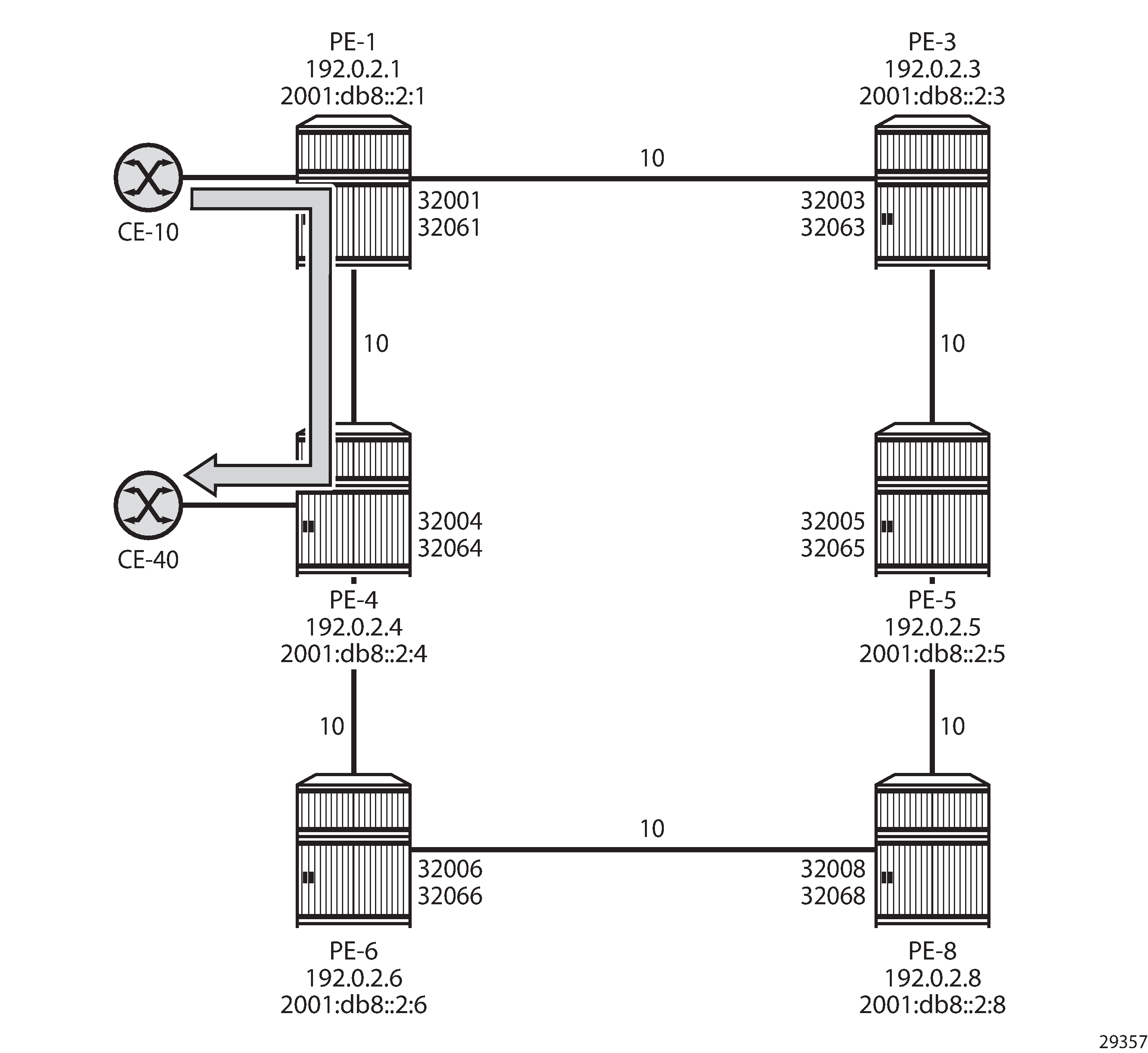
Example topology for remote LFA shows the example topology with six nodes in a ring. Traffic from CE-10 to CE-40 is preferably sent via PE-1 to PE-4.
The following command enables remote LFA on all nodes:
# on PE-1, PE-3, PE-4, PE-5, PE-6, PE-8:
configure
    router Base
        isis 0
            loopfree-alternates
                remote-lfa
If the link between PE-1 and PE-4 fails, the repair path on PE-1 can only use PE-3 as next-hop. Link-protection LFA inequality 1 is not valid, indicating that the backup path via next-hop PE-3 is not loop free:
With this invalid LFA inequality 1, no coverage with regular LFA is possible. When remote LFA is enabled, a repair tunnel is computed from PE-1 toward a node (PE-8) where the traffic is not looped back toward the computing node PE-1. When traffic emerges from the repair tunnel on PE-8, it is forwarded to the destination PE-4, using node SID 32004 for IPv4 or node SID 32064 for IPv6.
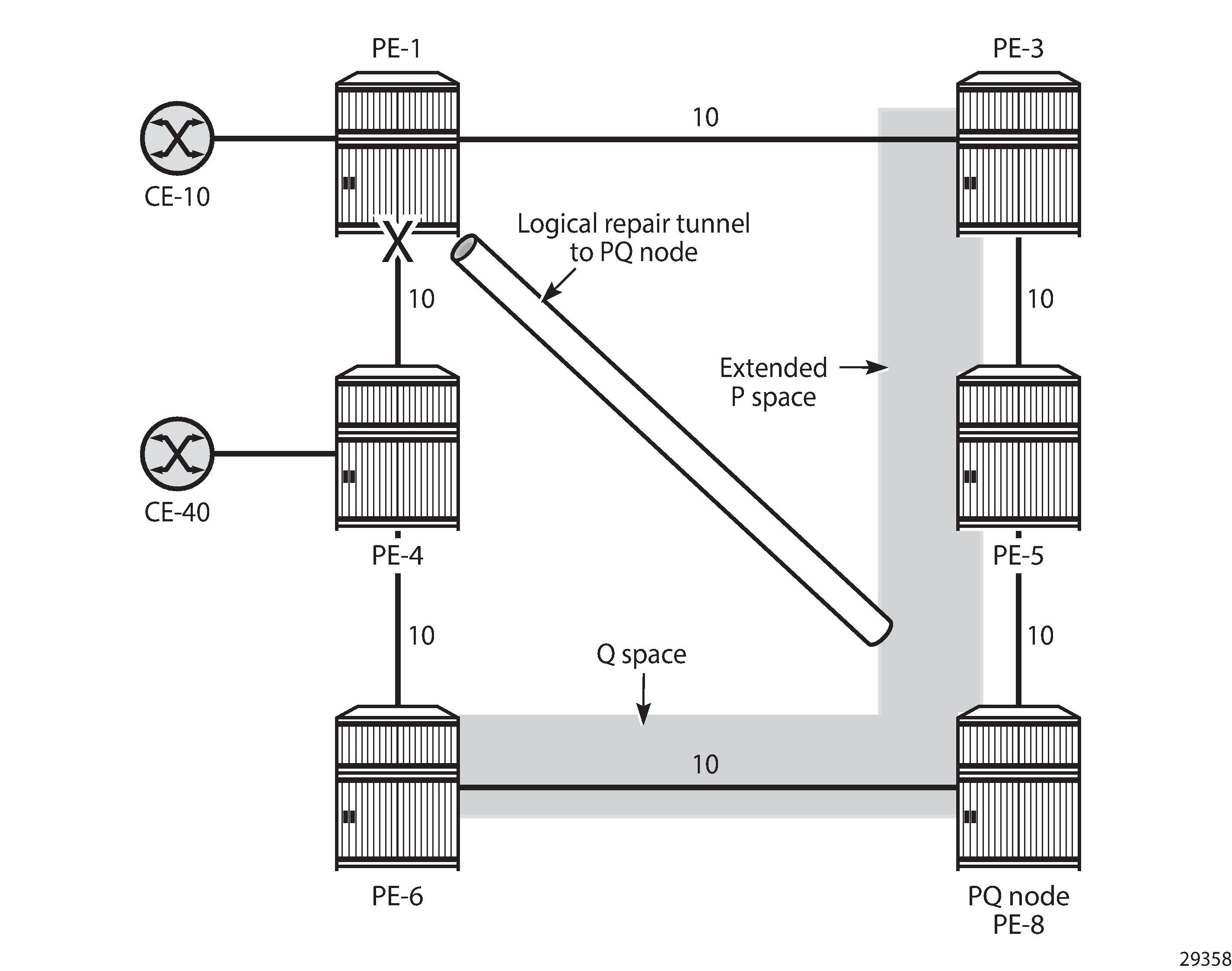
The endpoint node of the repair tunnel for remote LFA (RLFA) is the PQ node, which is in the intersection of the extended P space of source PE-1 and the Q space of destination PE-4.
The P space of PE-1 is the set of routers reachable on the shortest SPF path from the computing node PE-1, without using the protected link between PE-1 and PE-4; that is, SPF computed by PE-1 and rooted from PE-1. In this example, PE-3 and PE-5 are in the P space of PE-1.
The extended P space of PE-1 is the set of routers, calculated by PE-1, in the P space of the next-hop router PE-3. An additional SPF computation by PE-1 and rooted from PE-3 results in P nodes PE-3, PE-5, and PE-8. The extended P space increases the repair coverage.
The Q space of PE-4 is the set of routers that can reach the destination router PE-4 using the shortest path, without using the protected link; that is, reverse SPF computed by PE-1 and rooted from PE-4, resulting in Q nodes PE-6 and PE-8.
PQ routers are in the intersection of the extended P space and the Q space; in this case, the only PQ node is PE-8.
Repair tunnels are shortest path SR tunnels from the computing node PE-1 to the PQ router; in this case, from PE-1 to PE-8.
PQ node in remote LFA shows the extended P space of PE-1, comprising nodes PE-3, PE-5, and PE-8, and the Q space of PE-4, comprising nodes PE-6 and PE-8. In the event of a link failure, PE-1 will push the node SID of PE-8, along with the node SID of PE-4, and forward the packet toward the backup next-hop PE-8.
The following shows the SR LFA coverage on PE-1; the five other node SIDS are all protected: one with regular LFA and the remaining four with remote LFA (in the column RLFA). Besides the node SIDs, the adjacency SIDs toward the direct neighbors PE-3 and PE-4 are protected using RLFA. The LFA coverage is the same for IPv4 and IPv6.
*A:PE-1# show router isis sr-lfa-coverage

===============================================================================
Rtr Base ISIS Instance 0 SR LFA Coverage
===============================================================================
MT-ID   SidType      Level Proto LFA       RLFA      TILFA     Coverage
-------------------------------------------------------------------------------
0       node-sid     L1    ipv4  1(20%)    4(80%)    0(0%)     5/5(100%)
0       node-sid     L1    ipv6  1(20%)    4(80%)    0(0%)     5/5(100%)
---snip---
0       adj-sid      L1L2  ipv4  0(0%)     2(100%)   0(0%)     2/2(100%)
0       adj-sid      L1L2  ipv6  0(0%)     2(100%)   0(0%)     2/2(100%)
===============================================================================
The repair tunnel from PE-1 to PQ node PE-8 uses node SID 32008 for IPv4 and 32068 for IPv6.
The fifth entry in the following FP tunnel table shows that destination 192.0.2.8/32 of PE-8 is protected with regular LFA. The only label is 32008, which is the node SID of PE-8. All other destinations in the table are protected with remote LFA, having two node SID labels for the RLFA path, such as 32004/32008 for prefix 192.0.2.4 with next-hop 192.168.13.2 on PE-3. This means that the top label 32008 is pushed by PE-1 to match the repair-tunnel going via PE-3 to PQ-node PE-8. From PE-8 onward, the bottom label 32004 is used toward PE-4. Likewise, the other destinations in the list have top label 32008, so a tunnel is established to PE-8. The output is similar for IPv6.
*A:PE-1# show router fp-tunnel-table 1

===============================================================================
IPv4 Tunnel Table Display

Legend:
label stack is ordered from bottom-most to top-most
B - FRR Backup
===============================================================================
Destination                                  Protocol            Tunnel-ID
  Lbl
    NextHop                                                      Intf/Tunnel
  Lbl     (backup)
    NextHop   (backup)
-------------------------------------------------------------------------------
192.0.2.3/32                                 SR-ISIS-0            524295
  32003
    192.168.13.2                                                  1/1/3:1000
  32003/32008
    192.168.14.2(B)                                               1/1/2:1000
192.0.2.4/32                                 SR-ISIS-0            524299
  32004
    192.168.14.2                                                  1/1/2:1000
  32004/32008
    192.168.13.2(B)                                               1/1/3:1000
192.0.2.5/32                                 SR-ISIS-0            524301
  32005
    192.168.13.2                                                  1/1/3:1000
  32005/32008
    192.168.14.2(B)                                               1/1/2:1000
192.0.2.6/32                                 SR-ISIS-0            524311
  32006
    192.168.14.2                                                  1/1/2:1000
  32006/32008
    192.168.13.2(B)                                               1/1/3:1000
192.0.2.8/32                                 SR-ISIS-0            524313
  32008
    192.168.13.2                                                  1/1/3:1000
  32008
    192.168.14.2(B)                                               1/1/2:1000
192.168.13.2/32                              SR                   524309
  3
    192.168.13.2                                                  1/1/3:1000
  32003/32008
    192.168.14.2(B)                                               1/1/2:1000
192.168.14.2/32                              SR                   524297
  3
    192.168.14.2                                                  1/1/2:1000
  32004/32008
    192.168.13.2(B)                                               1/1/3:1000
-------------------------------------------------------------------------------
Total Entries : 7
-------------------------------------------------------------------------------
===============================================================================
TI-LFA
The following two use cases are described in this section:
Directed LFA where the extended P space and the Q space do not overlap
Extension of the RLFA algorithm to compute a repair path using directed LFA, but ensuring that the post-failure path matches the post-convergence path
Directed LFA
Extended P space of PE-1 and Q space of PE-4 are one hop apart shows the example topology with increased metric between PE-5 and PE-8, reducing the extended P space to PE-3 and PE-5, so there is no PQ node.
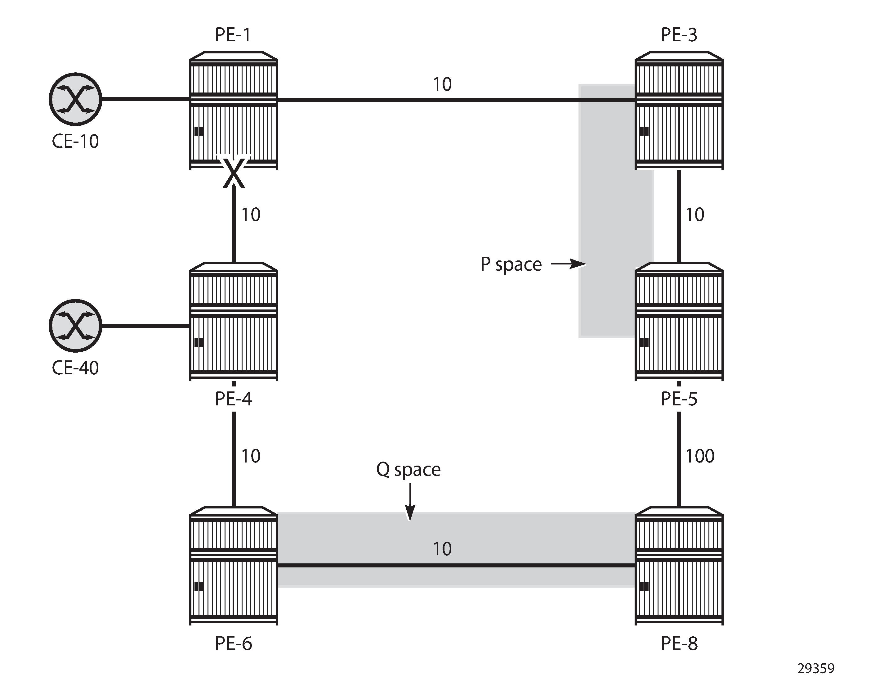
There is no remote LFA repair tunnel. No Q routers are on the shortest path from the computing router, and the P routers are not in the reverse SPF of the endpoint of the protected link. However, TI-LFA can calculate a repair tunnel in case the gap is only one or two hops. TI-LFA is enabled using the following command:
# on PE-1, PE-3, PE-4, PE-5, PE-6, PE-8:
configure
    router Base
        isis 0
            loopfree-alternates
                ti-lfa max-sr-frr-labels 2
Values of the max-sr-frr-labels parameter in TI-LFA lists the possible values of the max-sr-frr-labels parameter. This parameter is used to specify the maximum number of labels that the TI-LFA backup next-hop can use.
Max. SR-FRR labels |
LFA behavior |
|---|---|
0 |
Regular LFA: TI-LFA backup restricted to next-hop that does not require a repair tunnel, so PQ node is a neighbor of the computing node. |
1 |
Remote LFA: extended P space and Q space intersect and the repair tunnel requires 1 FRR label:
|
2 (default) |
TI-LFA with extended P space and Q space one hop apart:
|
3 |
TI-LFA with extended P space and Q space two hops apart:
|
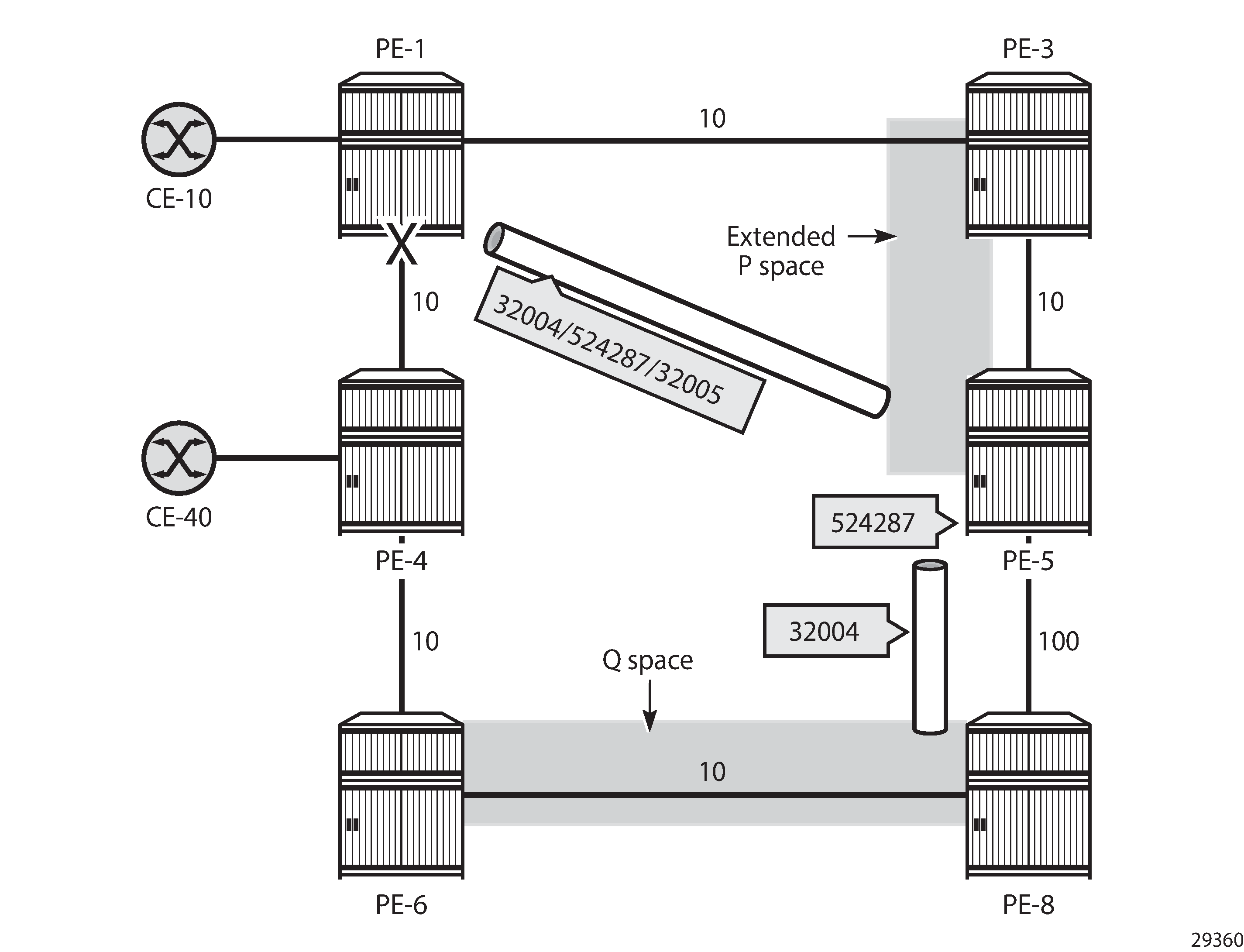
In this case, the extended P space and the Q space are one hop apart and TI-LFA calculates a post-failure path that consists of a repair tunnel to P router PE-5 (node SID 32005 for IPv4) and an adjacency SID toward Q router PE-8. For routes from PE-1 to PE-4, the LFA route has two additional labels combined with the bottom label that is the node SID of PE-4 (32004), which is also used for the primary path. The top label is the node SID of P router PE-5 (32005); the next label is the adjacency SID on PE-5 toward PE-8 (524287).
*A:PE-1# show router fp-tunnel-table 1 192.0.2.4/32

===============================================================================
IPv4 Tunnel Table Display

Legend:
label stack is ordered from bottom-most to top-most
B - FRR Backup
===============================================================================
Destination                                  Protocol            Tunnel-ID
  Lbl
    NextHop                                                      Intf/Tunnel
  Lbl     (backup)
    NextHop   (backup)
-------------------------------------------------------------------------------
192.0.2.4/32                                 SR-ISIS-0            524299
  32004
    192.168.14.2                                                  1/1/2:1000
  32004/524287/32005
    192.168.13.2(B)                                               1/1/3:1000
-------------------------------------------------------------------------------
Total Entries : 1
-------------------------------------------------------------------------------
===============================================================================
Directed LFA with P router and Q router one hop apart shows the directed LFA path from source PE-1 to P router PE-5 (node SID), the adjacency SID from P router PE-5 to Q router PE-8, and the node SID of destination PE-4. P router PE-5 uses the adjacency SID for forwarding, but only sends the packets with the node SID of PE-4 (32004).
TI-LFA for coinciding post-failure and post-convergence paths
Post-failure TI-LFA path coincides with post-convergence path is the same as Post-failure TI-LFA path matches post-convergence path and is repeated here for readability. The router interfaces have IGP metric 10 by default, except for the interfaces between PE-2 and PE-3 that have metric 20, and the interfaces between PE-4 and PE-6 that have metric 30. As in Directed LFA with P router and Q router one hop apart, Post-failure TI-LFA path coincides with post-convergence path shows the different tunnels used for the TI-LFA path. TI-LFA ensures that the post-failure path coincides with the post-convergence path by adding additional labels: the node SID 32002 (or 32062 for IPv6) to P router PE-2, the adjacency SID on PE-2 for the interface toward Q router PE-3, and the node SID 32005 (or 32065 for IPv6) toward the destination PE-5.
Regular LFA coverage
For a better comparison, the regular LFA coverage is calculated first. Without remote LFA and TI-LFA enabled, the LFA coverage is limited. The following command disables remote LFA and TI-LFA on all nodes, while regular LFA remains enabled:
# on all nodes:
configure
    router Base
        isis 0
            loopfree-alternates
                no remote-lfa
                no ti-lfa
            exit
The SR LFA coverage on PE-4 only protects node SIDs and adjacency SIDs that can be protected with regular LFA, as follows:
*A:PE-4# show router isis sr-lfa-coverage

===============================================================================
Rtr Base ISIS Instance 0 SR LFA Coverage
===============================================================================
MT-ID   SidType      Level Proto LFA       RLFA      TILFA     Coverage
-------------------------------------------------------------------------------
0       node-sid     L1    ipv4  5(71%)    0(0%)     0(0%)     5/7(71%)
0       node-sid     L1    ipv6  5(71%)    0(0%)     0(0%)     5/7(71%)
---snip---
0       adj-sid      L1L2  ipv4  2(66%)    0(0%)     0(0%)     2/3(66%)
0       adj-sid      L1L2  ipv6  2(66%)    0(0%)     0(0%)     2/3(66%)
===============================================================================
The following shows that no LFA paths exist on PE-4 for destinations 192.0.2.1 (PE-1), 192.0.2.2 (PE-2), and 192.168.14.1 (PE-1).
*A:PE-4# show router fp-tunnel-table 1

===============================================================================
IPv4 Tunnel Table Display

Legend:
label stack is ordered from bottom-most to top-most
B - FRR Backup
===============================================================================
Destination                                  Protocol            Tunnel-ID
  Lbl
    NextHop                                                      Intf/Tunnel
  Lbl     (backup)
    NextHop   (backup)
-------------------------------------------------------------------------------
192.0.2.1/32                                 SR-ISIS-0            524292
  32001
    192.168.14.1                                                  1/1/1:1000
192.0.2.2/32                                 SR-ISIS-0            524319
  32002
    192.168.14.1                                                  1/1/1:1000
192.0.2.3/32                                 SR-ISIS-0            524293
  32003
    192.168.45.2                                                  1/1/3:1000
  32003
    192.168.46.2(B)                                               1/1/2:1000
192.0.2.5/32                                 SR-ISIS-0            524299
  32005
192.168.45.2                                                  1/1/3:1000
  32005
192.168.46.2(B)                                               1/1/2:1000
192.0.2.6/32                                 SR-ISIS-0            524311
  32006
    192.168.46.2                                                  1/1/2:1000
  32006
    192.168.45.2(B)                                               1/1/3:1000
192.0.2.7/32                                 SR-ISIS-0            524323
  32007
    192.168.45.2                                                  1/1/3:1000
  32007
    192.168.46.2(B)                                               1/1/2:1000
192.0.2.8/32                                 SR-ISIS-0            524313
  32008
    192.168.45.2                                                  1/1/3:1000
  32008
    192.168.46.2(B)                                               1/1/2:1000
192.168.14.1/32                              SR                   524317
  3
    192.168.14.1                                                  1/1/1:1000
192.168.45.2/32                              SR                   524321
  3
    192.168.45.2                                                  1/1/3:1000
  32005
    192.168.46.2(B)                                               1/1/2:1000
192.168.46.2/32                              SR                   524309
  3
    192.168.46.2                                                  1/1/2:1000
  32006
    192.168.45.2(B)                                               1/1/3:1000
-------------------------------------------------------------------------------
Total Entries : 10
-------------------------------------------------------------------------------
===============================================================================
For destination 192.0.2.5, the post-failure path has next-hop 192.168.46.2 on PE-6, so the post-failure path does not coincide with the post-convergence path with next-hop 192.168.14.1 on PE-1. The path cost of the post-convergence path from PE-4 to PE-5 (via PE-1, PE-2, and PE-3) equals 10 + 10 + 20 + 10 = 50; the path cost of the post-failure path from PE-4 to PE-5 (via PE-6, PE-7, and PE-8) equals 30 + 10 + 10 + 10 = 60.
TI-LFA enabled
TI-LFA can be configured with remote LFA enabled or disabled. The following command configures remote LFA and TI-LFA (with default max-sr-frr-labels 2).
# on all nodes:
configure
    router Base
        isis 0
            loopfree-alternates
                remote-lfa
                exit
                ti-lfa max-sr-frr-labels 2
                exit
           exit
With TI-LFA enabled, the SR LFA coverage increases to 100%, as follows. For almost all destinations, the LFA protection is now using TI-LFA, even when regular LFA was possible before. The advantage is that TI-LFA ensures the post-failure path coincides with the post-convergence path.
If there is regular LFA protection via a path that does not coincide with the post-convergence path, that regular LFA protection will only change to TI-LFA protection when max-sr-frr-labels allows the needed number of labels (tunnels) to force the TI-LFA protection to the post-convergence path. The same applies for remote LFA protection.
*A:PE-4# show router isis sr-lfa-coverage

===============================================================================
Rtr Base ISIS Instance 0 SR LFA Coverage
===============================================================================
MT-ID   SidType      Level Proto LFA       RLFA      TILFA     Coverage
-------------------------------------------------------------------------------
0       node-sid     L1    ipv4  0(0%)     0(0%)     7(100%)   7/7(100%)
0       node-sid     L1    ipv6  0(0%)     0(0%)     7(100%)   7/7(100%)
---snip---
0       adj-sid      L1L2  ipv4  0(0%)     0(0%)     3(100%)   3/3(100%)
0       adj-sid      L1L2  ipv6  0(0%)     0(0%)     3(100%)   3/3(100%)
===============================================================================
The following FP tunnel table shows that prefixes 192.0.2.1 (PE-1), 192.0.2.2 (PE-2), and 192.168.14.1 (PE-1) are now protected too. For destination 192.0.2.5 (PE-5), the next-hop now is 192.168.14.1, which is also the next-hop on the post-convergence path to PE-5 via PE-1, PE-2, and PE-3. The top label 32002 is the node SID of PE-2, the label 524285 is the adjacency SID on PE-2 for the interface toward PE-3, and the bottom label 32005 is the node SID to reach the destination PE-5.
*A:PE-4# show router fp-tunnel-table 1

===============================================================================
IPv4 Tunnel Table Display

Legend:
label stack is ordered from bottom-most to top-most
B - FRR Backup
===============================================================================
Destination                                  Protocol            Tunnel-ID
  Lbl
    NextHop                                                      Intf/Tunnel
  Lbl     (backup)
    NextHop   (backup)
-------------------------------------------------------------------------------
192.0.2.1/32                                 SR-ISIS-0            524292
  32001
    192.168.14.1                                                  1/1/1:1000
  32001/524285/32003
    192.168.45.2(B)                                               1/1/3:1000
192.0.2.2/32                                 SR-ISIS-0            524319
  32002
    192.168.14.1                                                  1/1/1:1000
  32002/524285/32003
    192.168.45.2(B)                                               1/1/3:1000
192.0.2.3/32                                 SR-ISIS-0            524293
  32003
    192.168.45.2                                                  1/1/3:1000
  32003/524285/32002
    192.168.14.1(B)                                               1/1/1:1000
192.0.2.5/32                                 SR-ISIS-0            524299
  32005
192.168.45.2                                                  1/1/3:1000
  32005/524285/32002
192.168.14.1(B)                                               1/1/1:1000
192.0.2.6/32                                 SR-ISIS-0            524311
  32006
    192.168.46.2                                                  1/1/2:1000
  32006
    192.168.45.2(B)                                               1/1/3:1000
192.0.2.7/32                                 SR-ISIS-0            524323
  32007
    192.168.45.2                                                  1/1/3:1000
  32007
    192.168.46.2(B)                                               1/1/2:1000
192.0.2.8/32                                 SR-ISIS-0            524313
  32008
    192.168.45.2                                                  1/1/3:1000
  32008
    192.168.46.2(B)                                               1/1/2:1000
192.168.14.1/32                              SR                   524317
  3
    192.168.14.1                                                  1/1/1:1000
  32001/524285/32003
    192.168.45.2(B)                                               1/1/3:1000
192.168.45.2/32                              SR                   524321
  3
    192.168.45.2                                                  1/1/3:1000
  32005/524285/32002
    192.168.14.1(B)                                               1/1/1:1000
192.168.46.2/32                              SR                   524309
  3
    192.168.46.2                                                  1/1/2:1000
  32006
    192.168.45.2(B)                                               1/1/3:1000
-------------------------------------------------------------------------------
Total Entries : 10
-------------------------------------------------------------------------------
===============================================================================
The following tools command on PE-4 includes detailed information for the LFA protection for destination 192.0.2.5:
*A:PE-4# tools dump router isis sr-database prefix 192.0.2.5 detail
===============================================================================
Rtr Base ISIS Instance 0 SR Database

Legend:
label stack is ordered from bottom-most to top-most
===============================================================================
-------------------------------------------------------------------------------
SID 5
-------------------------------------------------------------------------------
Label              : 32005                 Adv System Id       : 1920.0000.2005
Prefix             : 192.0.2.5
Route Level        : 1                     MT Id               : 0
Rtm Preference     : 15                    Ttm Preference      : 11
Metric             : 10                    Last Action         : LfaNhops
Num Ip NextHop     : 1                     Num SR-Tnl NextHop  : 1
Mtu                : 8970
Mtu Prim           : 8982                  Mtu Backup          : 8982
Exclude from LFA   : 0                     LFA Type            : TI LFA
Duplicate Pending  : 0                     Tunnel Active State : Reported/Ack
SR Error           : SR_ERR_OK

LFA NextHop IP     : 192.168.14.1
LFA IsTunl         : N
LFA GIfId/TunlType : 1                     LFA IfId/LspId      : 2
LFA PgId           : 0                     LFA Adv Node        : False
LFA Labels         : 32005/524285/32002

NHOP: IP                       IsTunl GIfId/   IfId/ PgId  IsAdv Label   IsLfaX

                                      TunlType LspId
-------------------------------------------------------------------------------
192.168.45.2                   N      2        3     13    1     32005   0

-------------------------------------------------------------------------------
No. of Entries: 1
-------------------------------------------------------------------------------
LDP = LDP FEC is the SID NH for SR-LDP stitching
===============================================================================
TI-LFA enabled with max-sr-frr-labels lower than 2
When TI-LFA is configured with max-sr-frr-labels lower than 2, TI-LFA cannot substitute regular or remote LFA where more than 2 tunnel labels are needed for the substitution. Some destinations may remain protected then via regular or remote LFA, and only those destinations that can be protected with TI-LFA with less than 2 tunnel labels will have TI-LFA protection. The following configuration enables TI-LFA with max-sr-frr-labels equal to 1:
# on all nodes:
configure
    router Base
        isis 0
            loopfree-alternates
                remote-lfa
                exit
                ti-lfa max-sr-frr-labels 1
                exit
            exit
In the topology of Post-failure TI-LFA path coincides with post-convergence path, for max-sr-frr-labels equal to 1, the SR LFA coverage drops below 100% again, as follows.
*A:PE-4# show router isis sr-lfa-coverage

===============================================================================
Rtr Base ISIS Instance 0 SR LFA Coverage
===============================================================================
MT-ID   SidType      Level Proto LFA       RLFA      TILFA     Coverage
-------------------------------------------------------------------------------
0       node-sid     L1    ipv4  2(28%)    0(0%)     3(42%)    5/7(71%)
0       node-sid     L1    ipv6  2(28%)    0(0%)     3(42%)    5/7(71%)
---snip---
0       adj-sid      L1L2  ipv4  1(33%)    0(0%)     1(33%)    2/3(66%)
0       adj-sid      L1L2  ipv6  1(33%)    0(0%)     1(33%)    2/3(66%)
===============================================================================
The preceding information can be derived from the FP tunnel table and the SR database as follows. For PE-4, the FP tunnel table shows that there are 10 destinations, 7 nodes and 3 next-hops. 5 out of 7 node destinations and 2 out of 3 next-hop destinations are protected with a backup (B). Node destination 192.0.2.1 (PE-1), and 192.0.2.2 (PE-2), and next-hop destination 192.168.14.1 are no longer protected.
*A:PE-4# show router fp-tunnel-table 1

===============================================================================
IPv4 Tunnel Table Display

Legend:
label stack is ordered from bottom-most to top-most
B - FRR Backup
===============================================================================
Destination                                  Protocol            Tunnel-ID
  Lbl
    NextHop                                                      Intf/Tunnel
  Lbl     (backup)
    NextHop   (backup)
-------------------------------------------------------------------------------
192.0.2.1/32                                 SR-ISIS-0            524292
  32001
    192.168.14.1                                                  1/1/1:1000
192.0.2.2/32                                 SR-ISIS-0            524319
  32002
    192.168.14.1                                                  1/1/1:1000
192.0.2.3/32                                 SR-ISIS-0            524293
  32003
    192.168.45.2                                                  1/1/3:1000
  32003
    192.168.46.2(B)                                               1/1/2:1000
192.0.2.5/32                                 SR-ISIS-0            524299
  32005
    192.168.45.2                                                  1/1/3:1000
  32005
    192.168.46.2(B)                                               1/1/2:1000
192.0.2.6/32                                 SR-ISIS-0            524311
  32006
    192.168.46.2                                                  1/1/2:1000
  32006
    192.168.45.2(B)                                               1/1/3:1000
192.0.2.7/32                                 SR-ISIS-0            524323
  32007
    192.168.45.2                                                  1/1/3:1000
  32007
    192.168.46.2(B)                                               1/1/2:1000
192.0.2.8/32                                 SR-ISIS-0            524313
  32008
    192.168.45.2                                                  1/1/3:1000
  32008
    192.168.46.2(B)                                               1/1/2:1000
192.168.14.1/32                              SR                   524317
  3
    192.168.14.1                                                  1/1/1:1000
192.168.45.2/32                              SR                   524325
  3
    192.168.45.2                                                  1/1/3:1000
  32005
    192.168.46.2(B)                                               1/1/2:1000
192.168.46.2/32                              SR                   524309
  3
    192.168.46.2                                                  1/1/2:1000
  32006
    192.168.45.2(B)                                               1/1/3:1000
-------------------------------------------------------------------------------
Total Entries : 10
-------------------------------------------------------------------------------
===============================================================================
The SR database indicates what type of protection corresponds with the (topmost) label of the destinations in the FP tunnel tabel. Destination 192.0.2.1 (PE-1), 192.0.2.2 (PE-2), and 192.168.14.1 have no backup. Their label indicates that there is no LFA protection (LT = –). Destination 192.0.2.3 (PE-3), 192.0.2.5 (PE-5), and 192.168.45.2 have a backup with a (topmost) label that indicates regular LFA protection (LT = L). So, destination 192.0.2.5 (PE-5) is no longer TI-LFA protected, because that would require 2 tunnel labels, which max-sr-frr-labels=1 prevents. Destination 192.0.2.6 (PE-6), 192.0.2.7(PE-7), 192.0.2.8 (PE-8), and 192.168.46.2 have a backup with a (topmost) label that indicates TI-LFA protection (LT = T). As these destinations have no TI-LFA tunnel label, their TI-LFA protection does not need tunnels to ensure that the TI-LFA protection is via the post-convergence path.
The following tools command on PE-4 includes detailed information for the type of LFA protection that corresponds with a label:
*A:PE-4# tools dump router isis sr-database ipv4-unicast
===============================================================================
Rtr Base ISIS Instance 0 SR Database
===============================================================================
SID   Label  Prefix          Last-act  Lev MT RtmPref TtmPref Metric  IpNh SrNh
  Mtu    MtuPrim MtuBk  D xL LT Act AdvSystemId    SrErr
-------------------------------------------------------------------------------
1     32001  192.0.2.1       RemLfaNh  1   0  15      11      10      1    1
  8974   8982    -      0 0  -  +R  1920.0000.2001 SR_ERR_OK

2     32002  192.0.2.2       RemLfaNh  1   0  15      11      20      1    1
  8974   8982    -      0 0  -  +R  1920.0000.2002 SR_ERR_OK

3     32003  192.0.2.3       LfaNhops  1   0  15      11      20      1    1
  8974   8982    8982   0 0  L  +R  1920.0000.2003 SR_ERR_OK

4     32004  192.0.2.4       Local     -   -  -       -       -       -    -
  -      -       -      0 -  -  +R  1920.0000.2004 SR_ERR_OK

5     32005  192.0.2.5       LfaNhops  1   0  15      11      10      1    1
  8974   8982    8982   0 0  L  +R  1920.0000.2005 SR_ERR_OK

6     32006  192.0.2.6       TnlChange 1   0  15      11      30      1    1
  8974   8982    8982   0 0  T  +R  1920.0000.2006 SR_ERR_OK

7     32007  192.0.2.7       TnlChange 1   0  15      11      30      1    1
  8974   8982    8982   0 0  T  +R  1920.0000.2007 SR_ERR_OK

8     32008  192.0.2.8       TnlChange 1   0  15      11      20      1    1
  8974   8982    8982   0 0  T  +R  1920.0000.2008 SR_ERR_OK

-------------------------------------------------------------------------------
No. of Entries: 8
-------------------------------------------------------------------------------
Lev = route level
IpNh = number of IP next-hops
SrNh = number of SR-tunnel next-hops
D = duplicate pending
xL = exclude from LFA
LT = LFA type (L:LFA, R:RLFA, T:TILFA, n:nodeProtection)
Act = tunnel active state (R:reported, F:failed, +:SR-ack)
===============================================================================
Independent from the preceding ISIS Segment Routing LFA coverage (per Segment Routing LFA type and per ISIS Level), there is also the ISIS IP-routing LFA coverage (per IP version and per ISIS Level), as follows:
*A:PE-4# show router isis lfa-coverage

===============================================================================
Rtr Base ISIS Instance 0 LFA Coverage
===============================================================================
Topology         Level   Node           IPv4                IPv6
-------------------------------------------------------------------------------
IPV4 Unicast     L1      5/7(71%)       9/13(69%)           9/13(69%)
IPV6 Unicast     L1      0/0(0%)        0/0(0%)             0/0(0%)
IPV4 Multicast   L1      0/0(0%)        0/0(0%)             0/0(0%)
IPV6 Multicast   L1      0/0(0%)        0/0(0%)             0/0(0%)
IPV4 Unicast     L2      5/7(71%)       9/13(69%)           9/13(69%)
IPV6 Unicast     L2      0/0(0%)        0/0(0%)             0/0(0%)
IPV4 Multicast   L2      0/0(0%)        0/0(0%)             0/0(0%)
IPV6 Multicast   L2      0/0(0%)        0/0(0%)             0/0(0%)
===============================================================================
The preceding information can be derived from the table of alternative ISIS routes as follows. For PE-4, there are 17 routes: 8 routes to nodes and 9 routes to networks. The node and the networks that have 0.0.0.0 as next-hop must not be considered. This leaves (8 – 1) = 7 routes to nodes and (9 – 3) = 6 routes to networks. 5 out of 7 node destinations, and 4 out of 6 network destinations have an LFA next-hop (L). This leads to (5 + 4) / (7 + 6) = 9/13 IPv4 prefixes that have ISIS IP routing LFA coverage. A similar derivation applies for IPv6 prefixes.
*A:PE-4# show router isis routes ipv4-unicast alternative

===============================================================================
Rtr Base ISIS Instance 0 Route Table (alternative)
===============================================================================
Prefix[Flags]                     Metric     Lvl/Typ     Ver.  SysID/Hostname
  NextHop                                                MT     AdminTag/SID[F]
Alt-Nexthop                                              Alt-   Alt-Type
                                                        Metric
-------------------------------------------------------------------------------
192.0.2.1/32                      10         1/Int.      55    PE-1
   192.168.14.1                                            0       0/1[NnP]
192.0.2.2/32                      20         1/Int.      62    PE-1
   192.168.14.1                                            0       0/2[NnP]
192.0.2.3/32                      20         1/Int.      83    PE-5
   192.168.45.2                                            0       0/3[NnP]
   192.168.46.2(L)                                        70      LP
192.0.2.4/32                      0          1/Int.      2     PE-4
   0.0.0.0                                                 0       0/4[NnP]
192.0.2.5/32                      10         1/Int.      83    PE-5
   192.168.45.2                                            0       0/5[NnP]
   192.168.46.2(L)                                        60      LP
192.0.2.6/32                      30         1/Int.      70    PE-6
   192.168.46.2                                            0       0/6[NnP]
   192.168.45.2(L)                                        40      LP
192.0.2.7/32                      30         1/Int.      83    PE-5
   192.168.45.2                                            0       0/7[NnP]
   192.168.46.2(L)                                        40      NP
192.0.2.8/32                      20         1/Int.      83    PE-5
   192.168.45.2                                            0       0/8[NnP]
   192.168.46.2(L)                                        50      NP
192.168.12.0/30                   20         1/Int.      55    PE-1
   192.168.14.1                                            0       0
192.168.14.0/30                   10         1/Int.      4     PE-4
   0.0.0.0                                                 0       0
192.168.23.0/30                   40         1/Int.      83    PE-1
   192.168.14.1                                            0       0
192.168.35.0/30                   20         1/Int.      83    PE-5
   192.168.45.2                                            0       0
   192.168.46.2(L)                                        70      LP
192.168.45.0/30                   10         1/Int.      83    PE-4
   0.0.0.0                                                 0       0
192.168.46.0/30                   30         1/Int.      66    PE-4
   0.0.0.0                                                 0       0
192.168.58.0/30                   20         1/Int.      83    PE-5
   192.168.45.2                                            0       0
   192.168.46.2(L)                                        70      LP
192.168.67.0/30                   40         1/Int.      83    PE-5
   192.168.45.2                                            0       0
   192.168.46.2(L)                                        50      NP
192.168.78.0/30                   30         1/Int.      83    PE-5
   192.168.45.2                                            0       0
   192.168.46.2(L)                                        60      NP

-------------------------------------------------------------------------------
No. of Routes: 17 (17 paths)
-------------------------------------------------------------------------------
Flags        : L = Loop-Free Alternate nexthop
Alt-Type     : LP = linkProtection, NP = nodeProtection
SID[F]       : R  = Re-advertisement
               N  = Node-SID
               nP = no penultimate hop POP
               E  = Explicit-Null
               V  = Prefix-SID carries a value
               L  = value/index has local significance
===============================================================================
Conclusion
TI-LFA extends the calculation of a backup path for cases where the extended P space and the Q space do not overlap. TI-LFA also ensures that the post-failure path coincides with the post-convergence path, which avoids a switchover after SPF convergence.