Subscriber Redundancy for Routed CO
This chapter provides information about Subscriber Redundancy for Routed CO (SRRP).
Topics in this chapter include:
Applicability
This chapter is applicable to SR OS routers and was initially based on Release 7.0.R5. The CLI is updated to Release 16.0.R6.
Summary
This chapter focuses on the delivery of redundant services in an enhanced subscriber management (ESM) routed-CO environment using Internet enhanced service (IES) or virtual private routed network (VPRN).
It is applicable to delivering high speed Internet (HSI), voice-over-IP (VoIP) and video-on-demand (VoD) to subscribers.
Redundancy is provided at two levels:
system redundancy
network redundancy
The system redundancy is based on the high availability features of the SR OS routers, such as component redundancy (power, fans, control processor modules etc.) and software redundancy (service and protocol redundancy and non-stop-routing), which are not discussed here.
The network redundancy for subscriber access in an ESM routed CO environment requires that each broadband service access node (BSAN) is dual-homed to two SR OS routers, either in a point-to-point fashion with the BSANs having direct physical connectivity to the SR OS routers, or by having Layer 2 aggregation between the BSANs and the SR OS routers.
This connection will operate in a master-slave relationship providing both link and system redundancy for the subscribers on the BSAN when accessing the configured services.
Subscriber redundancy for routed-CO aims to minimize the outage due to a failure.
This chapter provides configuration and troubleshooting commands for SRRP with static-host ip-mac.
Knowledge of the triple play service delivery architecture (TPSDA) concepts is assumed throughout this document.
Overview
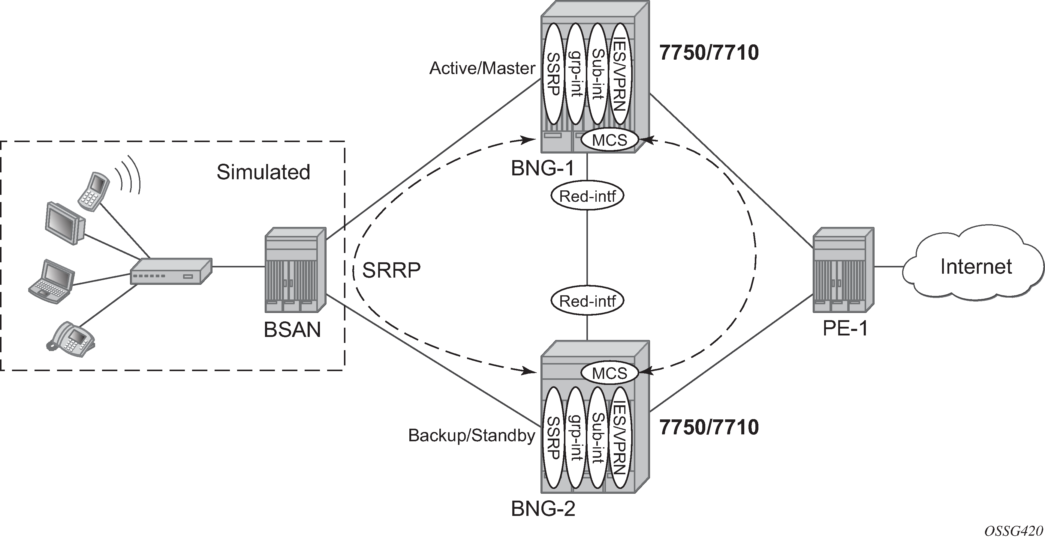
There are three components on SR OS routers to implement network redundancy:
Redundant access from the BSANs to two SR OS routers provided by the SRRP.
Mirroring of subscriber state between two SR OS routers is achieved through the multi-chassis synchronization (MCS) protocol.
Backup spoke SDP traffic path between two SR OS peers.
These components are shown in Network Redundancy Components for ESM Routed CO.
The following configuration tasks should be done first and are not explained in this chapter:
Basic service router configuration (system interface, IGP, MPLS, BGP)
Routed CO service topology: VPRN or IES service with subscriber and group interface on broadband network gateways (BNGs)
ESM configuration
Static host configuration
This chapter will focus on SRRP in a VPRN service subscriber-interface on BNG (routed-CO). In case of routed CO, it is also possible to configure SRRP in the base routing instance using an IES service.
SRRP Protocol
The SRRP protocol operates on a specific SAP within the group interface under the subscriber-interface of an IES/VPRN service. Through a method similar to the virtual router redundancy protocol (VRRP), it provides a set of default gateways to the subscribers on the BSAN. These are active on the SR OS router in the master state and inactive on the router in the backup state. Upstream and downstream traffic is forwarded through the master. If the backup loses connectivity with the master (for example, fails to receive SRRP messages from the master), it transitions to the master state and takes over the ownership of the default gateways and the responsibility for forwarding traffic to and from the subscriber. This provides redundancy from the BSAN toward the provider network.
If an SRRP fail over were to occur, it is important that the subscriber state (IP/MAC addresses, QOS profiles, etc.) be immediately available on the new SRRP master; otherwise, subscriber traffic will be dropped due to the anti-spoofing security. The subscriber state is synchronized through the MCS protocol, which mirrors the subscriber state between the two peers. This allows both peers to know the details of the active subscribers and therefore forward traffic on their behalf with the correct QOS actions both to and from the BSAN if that peer is the SRRP master.
The last topic relates to the forwarding from the provider network to the subscribers. If the IP routing causes this traffic to forward through the SRRP master, then the traffic will automatically be forwarded to the subscriber. However, if the provider routing scheme causes traffic destined to a subscriber to arrive at the router in the SRRP backup state for that subscriber, it will be dropped as the backup does not forward traffic out of the subscriber SAPs.
To avoid this, a redundant interface is configured between the two SR OS routers under the subscriber/group-interfaces. Any traffic arriving on the router for an active subscriber, where its associated SRRP instance is in the backup state, will be forwarded through the redundant interface to the SRRP master, which in turn forwards the traffic to the subscriber.
In addition to successful forwarding the traffic, this operation also maintains the subscriber QOS compliance as all traffic for a given subscriber enters and exits the routed-CO interface through a single SAP, allowing the associated IOM hardware to perform the correct QOS actions.
Configuration
Subscriber Interface Configuration
Redundant Default Gateway
The redundant default gateway IP addresses must be configured under the subscriber-interface (within the IES/VPRN service) for each subnet defined.
Three subnets are configured under the subscriber-interface sub-int-1, each with a gw-ip-address which is used as the default gateway by the subscribers in that subnet.
# on BNG-2
configure
    service
        vprn 1 customer 1 create
            ---snip---
            subscriber-interface "sub-int-1" create
                address 10.2.0.2/16 gw-ip-address 10.2.0.254
                address 10.3.0.2/16 gw-ip-address 10.3.0.254
                address 10.4.0.2/16 gw-ip-address 10.4.0.254
                ---snip---
            exit
        exit
    exit
exit
The gw-ip-address could be a virtual (unused) address in this subnet or the address of one of the actual subscriber-interfaces on the two routers, but it must not be used as a subscriber address.
If DHCP were to be used, the associated subscriber-interface address should be used as the gi-address configured for DHCP under the group-interface (will not be covered here as static host is used). This ensures that the offer returned from the DHCP server and arriving at the SRRP backup (rather than master) will be forwarded by the backup SRRP router to the master SRRP router through the redundant interface.
In environments where there are many subscribers, it will take time to synchronize the subscriber state between the peers when the subscriber-interface is enabled (perhaps, after a reboot). In order to ensure that the state has time to get synchronized, a hold timer can be applied to the subscriber interface. The optional init-only parameter can be added to use this timer only after a reboot.
*A:BNG-2>config>service>vprn>red-if>hold-time#
 [no] down            - Configure the hold time when the interface is coming up
 [no] up              - Configure the hold time when the interface is going down

*A:BNG-2>config>service>vprn>red-if>hold-time#
# on BNG-2
configure
    service
        vprn 1 customer 1 create
            subscriber-interface "sub-int-1" create
                hold-time
                    down ip 1200 init-only
                exit
            exit
        exit
    exit
Group Interface Configuration
The group interface group-int-1 providing connectivity to the BSAN is configured under the subscriber interface:
# on BNG-2
configure
    service
        vprn 1 customer 1 create
            subscriber-interface "sub-int-1" create
                group-interface "group-int-1" create
                ---snip---
            exit
        exit
    exit
exit
Static Host Configuration
First enable the sub-sla-mgmt and sub-ident-policy sub-id-default under sap 1/1/3:1, then define a static host (ip-mac) with sla-profile sla-profile-1, sub-profile sub-profile-1 and subscriber static-host-routed-10.2.0.3.
# on BGG-2
configure
    service
        vprn 1 customer 1 create
            subscriber-interface "sub-int-1" create
                group-interface "group-int-1" create
                    sap 1/1/3:1 create
                        sub-sla-mgmt
                            sub-ident-policy "sub-id-default"
                            multi-sub-sap
                            no shutdown
                        exit
                        static-host ip 10.2.0.3 mac 00:00:00:00:00:01 create
                            sla-profile "sla-profile-1"
                            sub-profile "sub-profile-1"
                            subscriber "static-host-routed-10.2.0.3"
                            no shutdown
                        exit
                    exit
                exit
            exit
        exit
    exit
exit
SRRP Configuration
In order for the redundant gateway information to be used by subscribers through SAPs belonging to a particular group-interface, an SRRP instance must be added in the group interface context.
# on BNG-2
configure
    service
        vprn 1 customer 1 create
            subscriber-interface "sub-int-1" create
                group-interface "group-int-1" create
                    srrp 1 create
                        ---snip---
                    exit
                exit
            exit
            no shutdown
        exit
    exit
exit
At this point, any subscriber ARPing for the gw-ip-address will receive a response from the SRRP master with a source MAC of 00-00-5E-00-01-<xx>, where <xx> is the first byte of the SRRP identifier in hexadecimal, so in this case for SRRP=1 the source MAC will be 00-00-5E-00-01-01.
The redundant default gateway MAC address could be explicitly configured, if desired, by use of the gw-mac parameter.
*A:BNG-2>config>service>vprn>sub-if>grp-if>srrp# gw-mac
  - gw-mac <mac-address>
  - no gw-mac

 <mac-address>        : xx:xx:xx:xx:xx:xx or xx-xx-xx-xx-xx-xx

*A:BNG-2>config>service>vprn>sub-if>grp-if>srrp#
There can be only one SRRP instance per group-interface and all SRRP identifiers must be unique per system.
When an SRRP instance is enabled, or when there is an SRRP failover from one device to another, gratuitous ARPs are sent on all VLANs associated with this instance for all gw-ip-addresses (for example, on all subscriber SAPs and on the SRRP message path SAP in the associated group interface). This allows all downstream devices to relearn the path to the new master.
The SRRP messages are normally forwarded through the BSAN, thereby verifying the connectivity from one router through the BSAN to the other router. In order to achieve this, a non-subscriber SAP must be configured under the group-interface which is referenced in the SRRP configuration by the message-path parameter. This not only selects the SAP to be used for the SRRP messages but also avoids the subscriber anti-spoofing from automatically dropping the received messages (as there would be no subscriber IP-to-MAC entry corresponding to the received information) and causing both peers to become master.
The message-path SAP configuration effectively disables IP-MAC anti-spoofing on that SAP.
# on BNG-2
configure
    service
        vprn 1 customer 1 create
            subscriber-interface "sub-int-1" create
                group-interface "group-int-1" create
                    ----snip---
                    sap 1/1/3:2 create
                    exit
                    srrp 1 create
                        message-path 1/1/3:2
                        no shutdown
                    exit
                exit
            exit
            no shutdown
        exit
    exit
exit
The SRRP messages are then not sent on the same SAP as the subscriber data traffic, under the assumption that the path traversed by the SRRP messages is the same as the path for the subscriber data; if this is not the case, then the SRRP state would not necessarily reflect a failure in the data path.
The master of the SRRP instance generates advertisement messages at the keep-alive-interval (which is encoded in the message) ranging from one (1) to 100 in multiples of 100ms with a default of 10 (for example, 1 second). The SRRP backup will monitor the reception of these messages and assume the role of the master if three consecutive messages are not received.
At all times the keep-alive-interval of the master is used.
*A:BNG-2>config>service>vprn>sub-if>grp-if>srrp# keep-alive-interval
  - keep-alive-interval <interval>
  - no keep-alive-interval

 <interval>           : [1..100] tenths of a second

*A:BNG-2>config>service>vprn>sub-if>grp-if>srrp#
Only two devices can participate in an SRRP protocol exchange for a given SRRP instance, this being another difference from VRRP which allows more potential backup devices. This is a consequence of the direct relationship between the SRRP instance and the associated redundant interface and MCS peering.
This protocol exchange is also used for the master/backup election, based on the priority (1 to 254) configured in the SRRP instance. The device with the highest priority will become master.
*A:BNG-2>config>service>vprn>sub-if>grp-if>srrp# priority
  - no priority
  - priority <priority>

 <priority>           : [1..254]

*A:BNG-2>config>service>vprn>sub-if>grp-if>srrp#
The message source IP address (system IP address) is used as a tie break when the priorities are the same (the lower IP address becomes the master). The master/backup status is per SRRP instance (not per IP address). For example, the master is the active gateway for all gw-ip-addresses under the subscriber interface for the associated group-interface (this is true even if the backup is the IP address owner for one of the gw-ip-addresses). Priority 0 is sent by the master when it is transitioning to the backup role due to the appearance of a high priority peer. Higher priority backups always preempt a lower priority master.
A basic form of load distribution can be achieved by having the master SRRP for some group-interfaces on one peer and the master for other group interfaces on the other peer. Clearly, a failure may cause all masters to be active on a single peer, which must be taken into account when designing the network.
The minimum keep-alive-timer of 1 is configured, together with the message-path defining the SAP to be used for the SRRP messages. The priority is set to 250 (default is 100) in order to force this peer to be the SRRP master when both peers are active.
# on BNG-2
configure
    service
        vprn 1 customer 1 create
            subscriber-interface "sub-int-1" create
                group-interface "group-int-1" create
                ---snip---
                srrp 1 create
                    keep-alive-interval 1
                    message-path 1/1/3:2
                    priority 250
                    no shutdown
                exit
            exit
        exit
SRRP Configuration Notes
A VRRP policy statement can be added to the SRRP instance definition in order to dynamically adjust the SRRP priority based on certain non-SRRP related events occurring (for example, port down, LAG degrade, host unreachable or route unknown).
The gw-ip-addresses are accessible by active subscribers, for example, regardless which peer is the master, an active subscriber can ping or telnet to its associated gw-ip-address (clearly, filters can be configured to control this).
Bi-directional Forwarding Detection
Bi-directional forwarding detection (BFD) can be configured with SRRP to speed up the convergence.
# on BNG-2
configure
    service
        vprn 1 customer 1 create
            subscriber-interface "sub-int-1" create
                group-interface "group-int-1" create
                ---snip---
                    srrp 1 create
                        ---snip---
                        bfd-enable 2 interface "bfd-1" dst-ip 10.1.1.1
                        no shutdown
                    exit
                exit
            exit
        exit
    exit
exit
An IES service needs to be created for the BFD session.
# on BNG-1
configure
    service
        ies 2 customer 1 create
            interface "bfd-1" create
                address 10.1.1.1/31
                bfd 100 receive 100 multiplier 3
                sap 1/1/3:3 create
                exit
            exit
            no shutdown
        exit
    exit
exit
Monitoring In-Band Communications Path
In order to monitor the in-band communications path between the subscribers and two routers, SRRP uses a slightly modified VRRP advertisement message.
The SRRP message destination IP address (224.0.0.18) and IP protocol number (112) are the same as for VRRP but there are changes in the following areas:
The source IP address of the message is the system IP address, as opposed to the interface IP address.
The protocol version has been set to eight (8) (the current version of VRRP is two (2)).
The source MAC address is included instead of the virtual router IP addresses (this being 00-00-5E-00-01-<xx>, where <xx> is the first byte of the SRRP identifier in hexadecimal).
Synchronizing the SRRP Peer State
In order to troubleshoot an SRRP environment, the state of each peer is synchronized with the other peer through multi-chassis synchronization (MCS). MCS is a proprietary protocol used for synchronizing application state between two peers. SRRP will function without synchronizing its state but this synchronization allows for the current state of both the local and remote peers to be displayed and appropriate error messages to be reported when the peer state is not correct. It also allows the master SRRP subscriber-interface to be pinged through the backup peer (through the redundant interface).
To link information being mirrored between two routers, a sync-tag value is configured to correspond to either an entire port/LAG or under a port/LAG for a VLAN range. This allows each router to know exactly which information should be in sync on each device. The sync-tag must be unique on the two peers involved.
This example configuration shows only the SRRP aspects. The SRRP instance has been configured for MCS peer 192.0.2.1 using VLANs 1-2 on port 1/1/3. Here, a sync-tag is associated with the SRRP instance.
# on BNG-2
configure
    redundancy
        multi-chassis
            peer 192.0.2.1 create
                authentication-key "sync-testing"
                sync
                    srrp
                    sub-mgmt ipoe
                    port 1/1/3 "st1" create
                        range 1-2 sync-tag "st1"
                    exit
                    no shutdown
                exit
                no shutdown
            exit
Alternatively, if the information needs to be synchronized for all VLANs on port 1/1/3, then the following port command could be used instead of the preceding port-plus-ranges shown.
# on BNG-2
configure
    redundancy
        multi-chassis
            peer 192.0.2.1 create
                authentication-key "sync-testing"
                sync
                    srrp
                    sub-mgmt ipoe
                    port 1/1/3 sync-tag "st1" create
                    exit
                    no shutdown
                exit
                no shutdown
            exit
The VLANs used within the group interfaces must match between the two peers, clearly the physical ports identifiers may differ.
Multi-Chassis Synchronization
Multi-chassis synchronization (MCS) is a general propriety protocol used to synchronize information between two peers. It can be used for the several applications, such as:
IGMP
IGMP snooping
Subscriber management
Subscriber router redundancy protocol
This chapter only covers the subscriber management and SRRP applications.
Subscriber Management Synchronization
In order to ensure that the QOS defined for a subscriber is adhered to, all traffic for a given subscriber needs to be forwarded by a single port. When an MSAN is dual-homed to two routers, this is achieved using the SRRP protocol (described above) and the redundant interface (described below); specifically, the traffic is forwarded through the SRRP master of the related group-interface.
When a subscriber is created on the master SRRP, a host route (/32) for its IP address is inserted in the FIB pointing towards the appropriate group-interface.
The same subscriber on the backup peer will have a host route in the IP FIB pointing to the redundant interface. On the backup peer, this requires the subscriber subnet to also be present in the FIB, which in turn requires one of the following:
The local subscriber-interface is up.
The subscriber subnets are learned from the active broadband network gateway (BNG) through the routing protocol.
Forcing the subscriber-interface to stay up by creating a dummy group interface with the oper-up-when-empty command.
# on BNG-2
configure
    service
        vprn 1 customer 1 create
            subscriber-interface "sub-int-1" create
                group-interface "group-int-1" create
                    oper-up-while-empty
                    sap 1/1/3:1 create
                        ---snip---
                    exit
                exit
            exit
        exit
    exit
exit
Redundant Interface
The requirement for the redundant interface stems from the situation where traffic destined to a subscriber arrives on the router where the associated SRRP state is not master.
When the SRRP state is backup for a particular group-interface, subscriber traffic is normally not forwarded in/out of the associated subscriber SAPs. Also traffic could arrive where the specific group-interface for that subscriber is down. These situations could occur due to the regular routing within the provider network or temporarily during an SRRP failover. Note that as the subscriber subnets are configured under the subscriber-interface, it is not possible to stop advertising these subnets into the provider core in the case where only a subset of the group interfaces are down or the associated SRRP instances are in backup. The advertisement of the subscriber subnet could therefore attract traffic to the router, while not being the SRRP master.
In these cases, traffic must be sent to the active SRRP router in order to be forwarded to the subscriber. This is achieved through the configuration of a redundant interface between two SRRP peers, protecting against failures of related group interfaces.
The redundant interface is configured under the IES/VRPN service. It must use a single pseudowire, configured as a spoke SDP, to provide connectivity to the peer router. This is essential as it avoids any possibility of the traffic being misrouted by any other system between the two peers. It can either use a /31 IP subnet mask or a longer mask with the remote IP being explicitly specified.
# on BRG-2
configure
    service
        vprn 1 customer 1 create
            ---snip---
            redundant-interface "bng-2-bng-1-vprn-1" create
                address 192.168.4.1/31
                spoke-sdp 21:1 create
                exit
            exit
            ---snip---
        exit
    exit
exit
If a non /31 address is used, the remote IP address will be required.
*A:BNG-2>config>service>vprn# redundant-interface "bng-2-bng-1-vprn-1"
*A:BNG-2>config>service>vprn>red-if# address 192.168.4.1/30
INFO: PIP #1399 Invalid or unspecified remote IP address - Non /31 address requires remote IP address
The remote-ip address can be defined by the following command:
*A:BNG-2>config>service>vprn>red-if# address 192.168.4.1/30 remote-ip 192.4.1.2
Then each group-interface must be assigned a redundant interface, as follows:
# on BNG-2
configure
    service
        vprn 1 customer 1 create
            ---snip---
            subscriber-interface "sub-int-1" create
                ---snip---
                group-interface "group-int-1" create
                    redundant-interface "bng-2-bng-1-vprn-1"
                    oper-up-while-empty
                    ---snip---
                exit
            exit
            no shutdown
        exit
    exit
exit
Only one redundant interface is required for a given IES/VPRN service on each peer, though it is possible to create multiple redundant interfaces and assign group interfaces to each individually. Clearly, each redundant interface needs to terminate on a matching redundant interface in the corresponding peer service.
When traffic arrives from the core network for an active subscriber on a SAP in group-interface group-int-1, and if the associated SRRP instance is in the backup state, then this traffic will be forwarded over the redundant-interface bng-2-bng-1-vprn-1 to the peer router. It will then be forwarded to the subscriber as the associated SRRP instance will be in the master state.
The information about the redundant interfaces is mirrored through MCS as part of the SRRP synchronization.
When changing the local and remote redundant-interface addresses afterward, shutdown and no shutdown of the redundant interface on one side is required in order to guarantee subscriber-interface IP reachability.
Show and Debug Commands
Routing Table Related Information
A host route (/32) for the static host is inserted in the FIB pointing toward the appropriate group-interface.
*A:BNG-2# show router 1 route-table protocol sub-mgmt

===============================================================================
Route Table (Service: 1)
===============================================================================
Dest Prefix[Flags]                            Type    Proto     Age        Pref
      Next Hop[Interface Name]                                    Metric
-------------------------------------------------------------------------------
10.2.0.1/32                                   Remote  Sub Mgmt  01h39m55s  0
       [bng-2-bng-1-vprn-1]                                         0
10.2.0.3/32                                   Remote  Sub Mgmt  02h05m21s  0
       [group-int-1]                                                0
10.3.0.1/32                                   Remote  Sub Mgmt  01h39m55s  0
       [bng-2-bng-1-vprn-1]                                         0
10.4.0.1/32                                   Remote  Sub Mgmt  01h39m55s  0
       [bng-2-bng-1-vprn-1]                                         0
-------------------------------------------------------------------------------
No. of Routes: 4
Flags: n = Number of times nexthop is repeated
       B = BGP backup route available
       L = LFA nexthop available
       S = Sticky ECMP requested
===============================================================================
*A:BNG-2#
The same subscriber on the backup peer will have a host route in the FIB pointing to the redundant interface.
*A:BNG-1# show router 1 route-table protocol sub-mgmt

===============================================================================
Route Table (Service: 1)
===============================================================================
Dest Prefix[Flags]                            Type    Proto     Age        Pref
      Next Hop[Interface Name]                                    Metric
-------------------------------------------------------------------------------
10.2.0.2/32                                   Remote  Sub Mgmt  01h42m50s  0
       [bng-1-bng-2-vprn-1]                                         0
10.2.0.3/32                                   Remote  Sub Mgmt  02h08m31s  0
       [bng-1-bng-2-vprn-1]                                         0
10.3.0.2/32                                   Remote  Sub Mgmt  01h42m50s  0
       [bng-1-bng-2-vprn-1]                                         0
10.4.0.2/32                                   Remote  Sub Mgmt  01h42m50s  0
       [bng-1-bng-2-vprn-1]                                         0
-------------------------------------------------------------------------------
No. of Routes: 4
Flags: n = Number of times nexthop is repeated
       B = BGP backup route available
       L = LFA nexthop available
       S = Sticky ECMP requested
===============================================================================
*A:BNG-1#
Subscriber Related Information
To check the subscriber information:
*A:BNG-2# show service id 1 subscriber-hosts

=============================================================
Subscriber Host table
=============================================================
Sap                    Subscriber
  IP Address
    MAC Address          PPPoE-SID Origin       Fwding State
-------------------------------------------------------------
1/1/3:1                static-host-routed-10.2.0.3
  10.2.0.3
    00:00:00:00:00:01    N/A       Static       Fwding
-------------------------------------------------------------
Number of subscriber hosts : 1
=============================================================
*A:BNG-2#
To check the subscriber details:
*A:BNG-2# show service id 1 subscriber-hosts mac 00:00:00:00:00:01 detail

=============================================================
Subscriber Host table
=============================================================
Sap                    Subscriber
  IP Address
    MAC Address          PPPoE-SID Origin       Fwding State
-------------------------------------------------------------
1/1/3:1                static-host-routed-10.2.0.3
  10.2.0.3
    00:00:00:00:00:01    N/A       Static       Fwding
-------------------------------------------------------------
Subscriber-interface  : sub-int-1
Group-interface       : group-int-1
Sub Profile           : sub-profile-1
SLA Profile           : sla-profile-1
App Profile           : N/A
Egress Q-Group        : N/A
Egress Vport          : N/A
Acct-Session-Id       : 021BFF000000005CA701E9
Acct-Q-Inst-Session-Id: 021BFF000000015CA701E9
Address Origin        : Static
OT HTTP Rdr IP-FltrId : N/A
OT HTTP Rdr Status    : N/A
OT HTTP Rdr Fltr Src  : N/A
HTTP Rdr URL Override : N/A
GTP local break-out   : No
DIAMETER session ID Gx: N/A
-------------------------------------------------------------
Number of subscriber hosts : 1
=============================================================
*A:BNG-2#
The same command on the peer would show the same information except for the port identifier part of the SAP, which is specific to the peer and may differ.
MCS Redundancy Related Information
The high-level state of MCS can be seen in the following output:
*A:BNG-2# show redundancy multi-chassis all

===============================================================================
Multi-Chassis Peers
===============================================================================
Peer Info                    Client    Admin        Oper         State
-------------------------------------------------------------------------------
Peer Address : 192.0.2.1
Source Addre*: 192.0.2.2
Peer Admin   : inService
Authenticati*: None
* indicates that the corresponding row element may have been truncated.
                             MC-Sync:  inService    inService    inSync
                             MC-Ring:  --           --           --
                             MC-Endpt: --           --           --
                             MC-Lag:   outOfService outOfService --
                             MC-IPsec: --           --           Disabled
===============================================================================
*A:BNG-2#
Information about the peering, the use of authentication, the state of MCS (Enabled) and the fact that MCS is inSync is shown.
*A:BNG-2# show redundancy multi-chassis sync

===============================================================================
Multi-chassis Peer Table
===============================================================================
Peer
-------------------------------------------------------------------------------
Peer IP Address         : 192.0.2.1
Description             : (Not Specified)
Authentication          : Enabled
Source IP Address       : 192.0.2.2
Admin State             : Enabled
Warm standby            : No
Remote warm standby     : No
-------------------------------------------------------------------------------
Sync-status
-------------------------------------------------------------------------------
Client Applications     : SUBMGMT-IPOE SUBMGMT-PPPOE SRRP
Sync Admin State        : Up
Sync Oper State         : Up
Sync Oper Flags         :
DB Sync State           : inSync
Num Entries             : 26
Lcl Deleted Entries     : 0
Alarm Entries           : 0
OMCR Standby Entries    : 0
OMCR Alarm Entries      : 0
Rem Num Entries         : 26
Rem Lcl Deleted Entries : 0
Rem Alarm Entries       : 0
Rem OMCR Standby Entries: 0
Rem OMCR Alarm Entries  : 0
===============================================================================
===============================================================================
*A:BNG-2#
In the output, it can be seen that SUBMGMT-IPOE, SUBMGMT-PPPOE and SRRP are client applications and they are inSync with 26 database entries both on this peer and the remote peer.
If the preceding command requested detailed output for peer 192.0.2.1, additional information would be shown.
*A:BNG-2# show redundancy multi-chassis sync peer 192.0.2.1 detail

===============================================================================
Multi-chassis Peer Table
===============================================================================
Peer
-------------------------------------------------------------------------------
Peer IP Address         : 192.0.2.1
Description             : (Not Specified)
Authentication          : Enabled
Source IP Address       : 192.0.2.2
Admin State             : Enabled
Warm standby            : No
Remote warm standby     : No
-------------------------------------------------------------------------------
Sync-status
-------------------------------------------------------------------------------
Client Applications     : SUBMGMT-IPOE SUBMGMT-PPPOE SRRP
Sync Admin State        : Up
Sync Oper State         : Up
Sync Oper Flags         :
DB Sync State           : inSync
Num Entries             : 26
Lcl Deleted Entries     : 0
Alarm Entries           : 0
OMCR Standby Entries    : 0
OMCR Alarm Entries      : 0
Rem Num Entries         : 26
Rem Lcl Deleted Entries : 0
Rem Alarm Entries       : 0
Rem OMCR Standby Entries: 0
Rem OMCR Alarm Entries  : 0

===============================================================================
MCS Application Stats
===============================================================================
Application             : igmp
Num Entries             : 0
Lcl Deleted Entries     : 0
Alarm Entries           : 0
OMCR Standby Entries    : 0
OMCR Alarm Entries      : 0

---snip---

-------------------------------------------------------------------------------
Application             : srrp
Num Entries             : 26
Lcl Deleted Entries     : 0
Alarm Entries           : 0
OMCR Standby Entries    : 0
OMCR Alarm Entries      : 0
-------------------------------------------------------------------------------
Rem Num Entries         : 26
Rem Lcl Deleted Entries : 0
Rem Alarm Entries       : 0
Rem OMCR Standby Entries: 0
Rem OMCR Alarm Entries  : 0
-------------------------------------------------------------------------------

---snip---

===============================================================================
Ports synced on peer 192.0.2.1
===============================================================================
Port/Encap                    Tag
-------------------------------------------------------------------------------
1/1/3                         st1
===============================================================================

---snip---

===============================================================================
Diameter proxy instances synced on peer 192.0.2.1
===============================================================================
Diameter-Peer-Policy             Tag
-------------------------------------------------------------------------------
No instances found
===============================================================================
===============================================================================
*A:BNG-2#
This shows that there are 26 entries on both peers for SRRP.
If the hold-time parameter is configured under the subscriber-interface, in order to allow time for the MCS to fully synchronize, its setting and current expiry time can be seen as follows:
A:BNG-2# show service id 1 interface "sub-int-1" detail

===============================================================================
Interface Table
===============================================================================

-------------------------------------------------------------------------------
Interface
-------------------------------------------------------------------------------
If Name          : sub-int-1
Admin State      : Up                   Oper (v4/v6)      : Down/--
Down Reason Code : delayedStartEnabled
Down Reason V4   : delayedStartEnabled
Down Reason V6   : ifProtoOperDown
Protocols        : None
IP Addr/mask     : 10.2.0.2/16
HoldUp-Time      : 0                    Track Srrp Inst   : 0
IP Addr/mask     : 10.3.0.2/16
HoldUp-Time      : 0                    Track Srrp Inst   : 0
IP Addr/mask     : 10.4.0.2/16
HoldUp-Time      : 0                    Track Srrp Inst   : 0
Ignore Port State: None
-------------------------------------------------------------------------------
Details
-------------------------------------------------------------------------------
Description      : (Not Specified)
If Index         : 5                    Virt. If Index    : 5
Last Oper Chg    : 08/18/2016 10:22:20  Global If Index   : 258
Mon Oper Grp     : None
Srrp En Rtng     : Disabled             Hold time         : N/A
V4 Delay IfUp    : 300 init-only        V4 Time to IfUp   : 278
                                        Unmatching Subnet : No
                                        Unmatching Pfxs   : No
If Type          : VPRN Sub

DHCP Details
Gi-Addr          : Not configured       Gi-Addr as Src Ip : Disabled
Virt. subnet     : disabled

===============================================================================
Interface sub-int-1 group-interfaces
===============================================================================
Interface-Name                   Adm       Opr(v4/v6)  Mode    Port/SapId
   IP-Address                                                  PfxState
-------------------------------------------------------------------------------
group-int-1                      Up        Up/--       VPRN G* 1/1/3
-------------------------------------------------------------------------------
Group-Interfaces : 1
===============================================================================
* indicates that the corresponding row element may have been truncated.
-------------------------------------------------------------------------------
Interfaces : 1
===============================================================================
A:BNG-2#
Tool Dump Commands Related Information
The database entries can be view in more detail with the tools dump redundancy multi-chassis command.
*A:BNG-2# tools dump redundancy multi-chassis sync-database

The following totals are for:
 peer ip ALL, port/lag/sdp ALL, sync-tag ALL, application ALL
Valid Entries:                   26
Locally Deleted Entries:         0
Locally Deleted Alarmed Entries: 0
Pending Global Delete Entries:   0
Omcr Alarmed Entries:            0
Omcr Standby Entries:            0
Associated Shared Records (ALL): 0
Associated Shared Records (LD):  0
*A:BNG-2#
The output of the ‟tool dump redundancy multi-chassis” command is as follows:
*A:BNG-2# tools dump redundancy multi-chassis srrp-sync-database
Tag Key:  sap = 1/1/3:2
Key Info: (Type/Owner)
   SMK_BASE_CONFIG / 192.0.2.1
Data Info:
    srrpId: 1    svcId: 1     svcType: VPRN
    system IP: 0xc0000201    Group interface MAC: 02:19:01:01:00:03
    Gateway MAC: 00:00:5e:00:01:01
    Subscriber interface name: sub-int-1

Tag Key:  sap = 1/1/3:2
Key Info: (Type/Owner)
   SMK_BASE_CONFIG / 192.0.2.2
Data Info:
    srrpId: 1    svcId: 1     svcType: VPRN
    system IP: 0xc0000202    Group interface MAC: 02:1b:01:01:00:03
    Gateway MAC: 00:00:5e:00:01:01
    Subscriber interface name: sub-int-1

Tag Key:  sap = 1/1/3:2
Key Info: (Type/Owner)
   SMK_GRP_IF / 192.0.2.1
Data Info:
    Group interface name: group-int-1
    Redundant interface name: bng-1-bng-2-vprn-1
    Redundant Interface IP/Mask:
        IP: 0xc0a80400 Mask: 0xfffffffe
    AdminUp: Up, OperState: SRRP_STATE_BACKUP_SHUNT, InUsePriority: 100, Red-If OK:
 Yes, MessageSap OK: Yes

Tag Key:  sap = 1/1/3:2
Key Info: (Type/Owner)
   SMK_GRP_IF / 192.0.2.2
Data Info:
    Group interface name: group-int-1
    Redundant interface name: bng-2-bng-1-vprn-1
    Redundant Interface IP/Mask:
        IP: 0xc0a80401 Mask: 0xfffffffe
    AdminUp: Up, OperState: SRRP_STATE_MASTER, InUsePriority: 250, Red-If OK: Yes,
 MessageSap OK: Yes

Tag Key:  sap = 1/1/3:2
Key Info: (Type/Owner)
   SMK_GRP_IF_SAP_BUCKET0 / 192.0.2.1
Data Info:

---snip---

Tag Key:  sap = 1/1/3:2
Key Info: (Type/Owner)
   SMK_GRP_IF_SAP_BUCKET9 / 192.0.2.2
Data Info:

Tag Key:  sap = 1/1/3:2
Key Info: (Type/Owner)
   SMK_SUBNET_INFO / 192.0.2.1 vRtrId 2, ifIdx 5
Data Info:
    Subscriber IP Addr: 10.2.0.1     Mask: 0xffff0000     Gateway: 10.2.0.254
    Subscriber IP Addr: 10.3.0.1     Mask: 0xffff0000     Gateway: 10.3.0.254
    Subscriber IP Addr: 10.4.0.1     Mask: 0xffff0000     Gateway: 10.4.0.254

Tag Key:  sap = 1/1/3:2
Key Info: (Type/Owner)
   SMK_SUBNET_INFO / 192.0.2.2 vRtrId 2, ifIdx 5
Data Info:
    Subscriber IP Addr: 10.2.0.2     Mask: 0xffff0000     Gateway: 10.2.0.254
    Subscriber IP Addr: 10.3.0.2     Mask: 0xffff0000     Gateway: 10.3.0.254
    Subscriber IP Addr: 10.4.0.2     Mask: 0xffff0000     Gateway: 10.4.0.254

*A:BNG-2#
Also shown are the port/VLANs synchronized with their respective sync-tags.
To further troubleshoot and debug this configuration, there are commands to both dump the sync and SRRP MCS information and to dump the SRRP database:
tools dump redundancy multi-chassis sync-database [application {sub-mgmt|srrp}]
The command provides the same information as the equivalent show commands. However, the detailed version gives more information about the contents of the sync-database.
For SRRP, there are entries for the base configuration, group interface and subnet information for each of the SRRP instances. This should show corresponding entries for the local and remote peer. Specifying the sync-tag st1 shows only the information for SRRP instance 1.
*A:BNG-2# tools dump redundancy multi-chassis sync-database application srrp
                                                               sync-tag st1 detail

If no entries are present for an application, no detail will be displayed.

FLAGS LEGEND: ld - local delete; da - delete alarm; pd - pending global delete;
              oal - omcr alarmed; ost - omcr standby

Peer Ip 192.0.2.1


Application SRRP
Sap-id             Client Key
 SyncTag                          DLen  Flags            timeStamp
  deleteReason code and description                   #ShRec
-------------------------------------------------------------------------------
1/1/3:2               SMK_BASE_CONFIG / 192.0.2.1
 st1                              88    -- -- -- --- --- 04/05/2019 09:46:39
  0x0                                                 0
1/1/3:2               SMK_BASE_CONFIG / 192.0.2.2
 st1                              88    -- -- -- --- --- 04/05/2019 09:46:39
  0x0                                                 0
1/1/3:2               SMK_GRP_IF / 192.0.2.1
 st1                              212   -- -- -- --- --- 04/05/2019 09:46:39
  0x0                                                 0
1/1/3:2               SMK_GRP_IF / 192.0.2.2
 st1                              212   -- -- -- --- --- 04/05/2019 09:46:39
  0x0                                                 0
1/1/3:2               SMK_GRP_IF_SAP_BUCKET0 / 192.0.2.1
 st1                              4     -- -- -- --- --- 04/05/2019 09:46:39
  0x0                                                 0

  ---snip---

1/1/3:2               SMK_GRP_IF_SAP_BUCKET9 / 192.0.2.2
 st1                              4     -- -- -- --- --- 04/05/2019 09:46:39
  0x0                                                 0
1/1/3:2               SMK_SUBNET_INFO / 192.0.2.1 vRtrId 2, ifIdx 5
 st1                              40    -- -- -- --- --- 04/05/2019 09:46:39
  0x0                                                 0
1/1/3:2               SMK_SUBNET_INFO / 192.0.2.2 vRtrId 2, ifIdx 5
 st1                              40    -- -- -- --- --- 04/05/2019 09:46:39
  0x0                                                 0

The following totals are for:
 peer ip ALL, port/lag/sdp ALL, sync-tag st1, application SRRP
Valid Entries:                   26
Locally Deleted Entries:         0
Locally Deleted Alarmed Entries: 0
Pending Global Delete Entries:   0
Omcr Alarmed Entries:            0
Omcr Standby Entries:            0
Associated Shared Records (ALL): 0
Associated Shared Records (LD):  0
*A:BNG-2#
The same information can be seen in more detail by dumping the SRRP database. This output is for SRRP instance 1, and shows the detailed information for each peer. This should clearly reflect the configuration and current state of the SRRP instances. Again there are two entries (one for the local peer and the other for the remote peer) for the BASE_CONFIG, GRP_IF and SUBNET_INFO.
*A:BNG-2# tools dump redundancy multi-chassis srrp-sync-database instance 1
Tag Key:  sap = 1/1/3:2
Key Info: (Type/Owner)
   SMK_BASE_CONFIG / 192.0.2.1
Data Info:
    srrpId: 1    svcId: 1     svcType: VPRN
    system IP: 0xc0000201    Group interface MAC: 02:19:01:01:00:03
    Gateway MAC: 00:00:5e:00:01:01
    Subscriber interface name: sub-int-1

Tag Key:  sap = 1/1/3:2
Key Info: (Type/Owner)
   SMK_BASE_CONFIG / 192.0.2.2
Data Info:
    srrpId: 1    svcId: 1     svcType: VPRN
    system IP: 0xc0000202    Group interface MAC: 02:1b:01:01:00:03
    Gateway MAC: 00:00:5e:00:01:01
    Subscriber interface name: sub-int-1

Tag Key:  sap = 1/1/3:2
Key Info: (Type/Owner)
   SMK_GRP_IF / 192.0.2.1
Data Info:
    Group interface name: group-int-1
    Redundant interface name: bng-1-bng-2-vprn-1
    Redundant Interface IP/Mask:
        IP: 0xc0a80400 Mask: 0xfffffffe
    AdminUp: Up, OperState: SRRP_STATE_BACKUP_SHUNT, InUsePriority: 100, Red-If OK:
 Yes, MessageSap OK: Yes

Tag Key:  sap = 1/1/3:2
Key Info: (Type/Owner)
   SMK_GRP_IF / 192.0.2.2
Data Info:
    Group interface name: group-int-1
    Redundant interface name: bng-2-bng-1-vprn-1
    Redundant Interface IP/Mask:
        IP: 0xc0a80401 Mask: 0xfffffffe
    AdminUp: Up, OperState: SRRP_STATE_MASTER, InUsePriority: 250, Red-If OK: Yes,
 MessageSap OK: Yes

Tag Key:  sap = 1/1/3:2
Key Info: (Type/Owner)
   SMK_GRP_IF_SAP_BUCKET0 / 192.0.2.1
Data Info:

Tag Key:  sap = 1/1/3:2
Key Info: (Type/Owner)
   SMK_GRP_IF_SAP_BUCKET0 / 192.0.2.2
Data Info:

---snip---

Tag Key:  sap = 1/1/3:2
Key Info: (Type/Owner)
   SMK_GRP_IF_SAP_BUCKET9 / 192.0.2.1
Data Info:

Tag Key:  sap = 1/1/3:2
Key Info: (Type/Owner)
   SMK_GRP_IF_SAP_BUCKET9 / 192.0.2.2
Data Info:

Tag Key:  sap = 1/1/3:2
Key Info: (Type/Owner)
   SMK_SUBNET_INFO / 192.0.2.1 vRtrId 2, ifIdx 5
Data Info:
    Subscriber IP Addr: 10.2.0.1     Mask: 0xffff0000     Gateway: 10.2.0.254
    Subscriber IP Addr: 10.3.0.1     Mask: 0xffff0000     Gateway: 10.3.0.254
    Subscriber IP Addr: 10.4.0.1     Mask: 0xffff0000     Gateway: 10.4.0.254

Tag Key:  sap = 1/1/3:2
Key Info: (Type/Owner)
   SMK_SUBNET_INFO / 192.0.2.2 vRtrId 2, ifIdx 5
Data Info:
    Subscriber IP Addr: 10.2.0.2     Mask: 0xffff0000     Gateway: 10.2.0.254
    Subscriber IP Addr: 10.3.0.2     Mask: 0xffff0000     Gateway: 10.3.0.254
    Subscriber IP Addr: 10.4.0.2     Mask: 0xffff0000     Gateway: 10.4.0.254

*A:BNG-2#
The following is an example of messages that could be seen due to this synchronization which otherwise would not be available.
An event will be generated in log 99, if the IP address was removed from the redundant interface on the remote peer.
*A:BNG-2# show log log-id 99 ascending

---snip---

89 2019/04/05 12:14:37.258 CEST WARNING: MC_REDUNDANCY #2012 vprn1 SRRP/MCS: Peer
                                                                   Red i/f no addr
"SRRP ID 1: Redundant interface bng-1-bng-2-vprn-1 on peer 192.0.2.1 / interface
group-int-1 does not match local 192.0.2.2 / interface group-int-1."

90 2019/04/05 12:14:37.258 CEST WARNING: MC_REDUNDANCY #2012 vprn1 SRRP/MCS: Peer
                                                                   Red i/f down
"SRRP ID 1: Redundant interface bng-1-bng-2-vprn-1 on peer 192.0.2.1 / interface
group-int-1 does not match local 192.0.2.2 / interface group-int-1."

*A:BNG-2#
The SRRP Instance Related Information
The SRRP instance information can be displayed by the following commands:
The master BNS shows the master in the operation status.
*A:BNG-2# show srrp

===============================================================================
SRRP Table
===============================================================================
ID        Service        Group Interface                 Admin     Oper
-------------------------------------------------------------------------------
1         1              group-int-1                     Up        master
-------------------------------------------------------------------------------
No. of SRRP Entries: 1
===============================================================================
*A:BNG-2#
The backup BNG shows a backupShunt in the operation status.
*A:BNG-1# show srrp

===============================================================================
SRRP Table
===============================================================================
ID        Service        Group Interface                 Admin     Oper
-------------------------------------------------------------------------------
1         1              group-int-1                     Up        backupShunt
-------------------------------------------------------------------------------
No. of SRRP Entries: 1
===============================================================================
*A:BNG-1#
To check detailed information:
*A:BNG-2# show srrp 1 detail

===============================================================================
SRRP Instance 1
===============================================================================
Description         : (Not Specified)
Admin State         : Up                 Oper State       : master
Preempt             : yes                One GARP per SAP : no
Monitor Oper Group  : None
System IP           : 192.0.2.2
Service ID          : VPRN 1
Group If            : group-int-1        MAC Address      : 02:1b:01:01:00:03
Grp If Description  : N/A
Grp If Admin State  : Up                 Grp If Oper State: Up
Subscriber If       : sub-int-1
Sub If Admin State  : Up                 Sub If Oper State: Up
Address             : 10.2.0.2/16        Gateway IP       : 10.2.0.254
Address             : 10.3.0.2/16        Gateway IP       : 10.3.0.254
Address             : 10.4.0.2/16        Gateway IP       : 10.4.0.254
Redundant If        : bng-2-bng-1-vprn-1
Red If Admin State  : Up                 Red If Oper State: Up
Address             : 192.168.4.1/31
Red Spoke-sdp       : 21:1
Msg Path SAP        : 1/1/3:2
Admin Gateway MAC   :                    Oper Gateway MAC : 00:00:5e:00:01:01
Config Priority     : 250                In-use Priority  : 250
Master Priority     : 250
Keep-alive Interval : 1 deci-seconds     Master Since     : 04/05/2019 09:21:14
Fib Population Mode : all
VRRP Policy 1       : None               VRRP Policy 2    : None

-------------------------------------------------------------------------------
BFD interface
-------------------------------------------------------------------------------
Service ID          : 2
Interface Name      : bfd-1
Src IP              : 10.1.1.0
Dst IP              : 10.1.1.1
Session Oper State  : connected

-------------------------------------------------------------------------------
Statistics
-------------------------------------------------------------------------------
Become Master       : 1                  Master Changes   : 1
Become Bkup Routing : 1                  Become Bkup Shunt: 1
Become Non-Master   : 0
Adv Sent            : 151493             Adv Received     : 3
Pri 0 Pkts Sent     : 0                  Pri 0 Pkts Rcvd  : 0
Preempt Events      : 1                  Preempted Events : 0
Mesg Intvl Discards : 0                  Mesg Intvl Errors: 0

===============================================================================
*A:BNG-2#
If this command is executed on the backup (BNG-1), an extra line appears after the keep-alive-interval showing the interval during which the receipt of no SRRP messages would cause the master to be considered down, together with the instantaneous time to this interval expiring.
*A:BNG-1# show srrp 1 detail

===============================================================================
SRRP Instance 1
===============================================================================
Description         : (Not Specified)
Admin State         : Up                 Oper State       : backupShunt
Preempt             : yes                One GARP per SAP : no
Monitor Oper Group  : None
System IP           : 192.0.2.1
Service ID          : VPRN 1
Group If            : group-int-1        MAC Address      : 02:19:01:01:00:03
Grp If Description  : N/A
Grp If Admin State  : Up                 Grp If Oper State: Up
Subscriber If       : sub-int-1
Sub If Admin State  : Up                 Sub If Oper State: Up
Address             : 10.2.0.1/16        Gateway IP       : 10.2.0.254
Address             : 10.3.0.1/16        Gateway IP       : 10.3.0.254
Address             : 10.4.0.1/16        Gateway IP       : 10.4.0.254
Redundant If        : bng-1-bng-2-vprn-1
Red If Admin State  : Up                 Red If Oper State: Up
Address             : 192.168.4.0/31
Red Spoke-sdp       : 12:1
Msg Path SAP        : 1/1/3:2
Admin Gateway MAC   :                    Oper Gateway MAC : 00:00:5e:00:01:01
Config Priority     : 100                In-use Priority  : 100
Master Priority     : 250
Keep-alive Interval : 1 deci-seconds     Master Since     : 04/05/2019 09:21:14
Master Down Interval: 0.300 sec (Expires in 0.250 sec)
Fib Population Mode : all
VRRP Policy 1       : None               VRRP Policy 2    : None

-------------------------------------------------------------------------------
BFD interface
-------------------------------------------------------------------------------
Service ID          : 2
Interface Name      : bfd-1
Src IP              : 10.1.1.1
Dst IP              : 10.1.1.0
Session Oper State  : connected

-------------------------------------------------------------------------------
Statistics
-------------------------------------------------------------------------------
Become Master       : 1                  Master Changes   : 2
Become Bkup Routing : 2                  Become Bkup Shunt: 2
Become Non-Master   : 1
Adv Sent            : 148                Adv Received     : 151469
Pri 0 Pkts Sent     : 1                  Pri 0 Pkts Rcvd  : 0
Preempt Events      : 0                  Preempted Events : 1
Mesg Intvl Discards : 0                  Mesg Intvl Errors: 0

===============================================================================
*A:BNG-1#
Monitoring the Traffic on Redundant Interface
The Oper State reflects both the state of the SRRP instance and its action with respect to the redundant interface. Specifically, when the peer is SRRP master the operational state is always master – traffic is sent directly to the subscriber over its associated SAP. If the peer is SRRP backup and the redundant interface is Up then the Oper State will be backupShunt, if the redundant interface is down then the Oper State is backupRouting. In the backupShunt state, traffic to the subscriber is shunted (for example, forwarded) across the redundant interface to the peer (to the master) in order to be forwarded to the subscriber.
When in the backupRouting state, the SRRP instance is in backup but the redundant interface is down, so the traffic is forwarded directly to the subscriber through its associated SAP.
A useful command to see the traffic on the redundant interface is:
*A:BNG-2# monitor service id 1 sdp 21:1 rate interval 11 repeat 3

===============================================================================
Monitor statistics for Service 1 SDP binding 21:1
===============================================================================
-------------------------------------------------------------------------------
At time t = 0 sec (Base Statistics)
-------------------------------------------------------------------------------
I. Fwd. Pkts.   : 193                   I. Dro. Pkts.   : 0
I. Fwd. Octs.   : 6076                  I. Dro. Octs.   : 0
E. Fwd. Pkts.   : 49                    E. Fwd. Octets  : 3022

-------------------------------------------------------------------------------
At time t = 11 sec (Mode: Rate)
-------------------------------------------------------------------------------
I. Fwd. Pkts.   : 1                     I. Dro. Pkts.   : 0
I. Fwd. Octs.   : 84                    I. Dro. Octs.   : 0
E. Fwd. Pkts.   : 1                     E. Fwd. Octets  : 98

-------------------------------------------------------------------------------
At time t = 22 sec (Mode: Rate)
-------------------------------------------------------------------------------
I. Fwd. Pkts.   : 1                     I. Dro. Pkts.   : 0
I. Fwd. Octs.   : 84                    I. Dro. Octs.   : 0
E. Fwd. Pkts.   : 1                     E. Fwd. Octets  : 98

-------------------------------------------------------------------------------
At time t = 33 sec (Mode: Rate)
-------------------------------------------------------------------------------
I. Fwd. Pkts.   : 1                     I. Dro. Pkts.   : 0
I. Fwd. Octs.   : 87                    I. Dro. Octs.   : 0
E. Fwd. Pkts.   : 1                     E. Fwd. Octets  : 98

===============================================================================
*A:BNG-2#
BFD-Related Information
To check the BFD session state.
*A:BNG-2# show router bfd session

===============================================================================
Legend:
  Session Id = Interface Name | LSP Name | Prefix | RSVP Sess Name | Service Id
  wp = Working path   pp = Protecting path
===============================================================================
BFD Session
===============================================================================
Session Id                                        State      Tx Pkts    Rx Pkts
  Rem Addr/Info/SdpId:VcId                      Multipl     Tx Intvl   Rx Intvl
  Protocols                                        Type     LAG Port     LAG ID
-------------------------------------------------------------------------------
bfd-1                                                Up       143677     143677
  10.1.1.1                                            3          100        100
  srrp                                              iom          N/A        N/A
-------------------------------------------------------------------------------
No. of BFD sessions: 1
===============================================================================
*A:BNG-2#
To check the MAC addresses of the SRRP, this is can be done by checking the MACs table in the BSAN.
*A:DSLAM# show service fdb-mac

===============================================================================
Service Forwarding Database
===============================================================================
ServId     MAC               Source-Identifier       Type     Last Change
            Transport:Tnl-Id                         Age
-------------------------------------------------------------------------------
1          00:00:00:00:00:01 sap:1/2/1:1             L/0      04/05/19 14:53:54
1          00:00:5e:00:01:01 sap:1/1/2:1             L/0      04/05/19 14:53:51
1          02:19:01:01:00:03 sap:1/1/1:1             L/0      04/05/19 14:53:55
1          02:1b:01:01:00:03 sap:1/1/2:1             L/0      04/05/19 14:57:53
2          00:00:5e:00:01:01 sap:1/1/2:2             L/0      04/05/19 14:53:51
-------------------------------------------------------------------------------
No. of Entries: 5
-------------------------------------------------------------------------------
Legend:  L=Learned O=Oam P=Protected-MAC C=Conditional S=Static Lf=Leaf
===============================================================================
*A:DSLAM#
SRRP Debug Commands
There are debug command to show the SRRP protocol events and packets.
*A:BNG-2# debug router 1 srrp events
*A:BNG-2# debug router 1 srrp packets
To display the debugging information, a dedicated log should be created:
configure
    log
        log-id 1
            from debug-trace
            to memory 3000
            no shutdown
        exit
    exit
exit
The following output displays a sample SRRP debug log:
2558 2019/04/05 13:57:55.104 CEST MINOR: DEBUG #2001 vprn1 SRRP
"SRRP: Receiving Pkt

Version (SRRP)     : 8
Type               : Advertisement (1)
Vr Id              : 1
Priority           : 250
Count Ip Addresses : 3
Advertise Interval : 10 centi-second
Checksum           : 0x21ef

Raw Pkt:

81 00 fe 00 00 00 00 01 00 00 5e 00 01 01 00 0a
00 03 21 ef "
An example SRRP message captured with tshark looks as follows:
Frame 1 (60 bytes on wire, 60 bytes captured)
    Arrival Time: Apr  8, 2019 09:20:52.989717000
    [Time delta from previous captured frame: 0.000000000 seconds]
    [Time delta from previous displayed frame: 0.000000000 seconds]
    [Time since reference or first frame: 0.000000000 seconds]
    Frame Number: 1
    Frame Length: 60 bytes
    Capture Length: 60 bytes
    [Frame is marked: False]
    [Protocols in frame: eth:vlan:ip:vrrp]
Ethernet II, Src: IETF-VRRP-virtual-router-VRID_01 (00:00:5e:00:01:01),
                           Dst: IPv4mcast_00:00:12 (01:00:5e:00:00:12)
    Destination: IPv4mcast_00:00:12 (01:00:5e:00:00:12)
        Address: IPv4mcast_00:00:12 (01:00:5e:00:00:12)
        .... ...1 .... .... .... .... = IG bit: Group address
                                                       (multicast/broadcast)
        .... ..0. .... .... .... .... = LG bit: Globally unique address
                                                           (factory default)
    Source: IETF-VRRP-virtual-router-VRID_01 (00:00:5e:00:01:01)
        Address: IETF-VRRP-virtual-router-VRID_01 (00:00:5e:00:01:01)
        .... ...0 .... .... .... .... = IG bit: Individual address (unicast)
        .... ..0. .... .... .... .... = LG bit: Globally unique address
                                                           (factory default)
    Type: 802.1Q Virtual LAN (0x8100)
802.1Q Virtual LAN, PRI: 0, CFI: 0, ID: 2
    000. .... .... .... = Priority: 0
    ...0 .... .... .... = CFI: 0
    .... 0000 0000 0010 = ID: 2
    Type: IP (0x0800)
    Trailer: 0000
Internet Protocol, Src: 192.0.2.2 (192.0.2.2), Dst: 224.0.0.18 (224.0.0.18)
    Version: 4
    Header length: 20 bytes
    Differentiated Services Field: 0xc0 (DSCP 0x30: Class Selector 6; ECN: 0x00)
        1100 00.. = Differentiated Services Codepoint: Class Selector 6 (0x30)
        .... ..0. = ECN-Capable Transport (ECT): 0
        .... ...0 = ECN-CE: 0
    Total Length: 40
    ---snip---
    Protocol: VRRP (0x70)
    Header checksum: 0x1f66 [correct]
        [Good: True]
        [Bad : False]
    Source: 192.0.2.2 (192.0.2.2)
    Destination: 224.0.0.18 (224.0.0.18)
Virtual Router Redundancy Protocol
    Version 8, Packet type 1 (Advertisement)
        1000 .... = VRRP protocol version: 8
        .... 0001 = VRRP packet type: Advertisement (1)
    Virtual Rtr ID: 0
    Priority: 250 (Non-default backup priority)
    Count IP Addrs: 0
    Auth Type: No Authentication (0)
    Adver Int: 0
    Checksum: 0x0001 [correct]
As an example, in the following output BNG-2 is the SRRP master for instance 1 and sends SRRP advertisement messages. Then BNG-2 receives an SRRP message with a higher priority (254) from its peer BNG-1. This causes an event Become Pending-Backup Shunt where BNG-2 prepares to transition to the backup state. To achieve this, BNG-2 sends and SRRP message with priority 0. If BNG-2 continues to receive priority 254 SRRP messages from its peer BNG-1, it passes into the backup state with the event Become Backup Shunt.
3267 2019/04/08 08:57:13.388 CEST MINOR: DEBUG #2001 vprn1 SRRP
"SRRP: Sending Pkt

Version (SRRP)     : 8
Type               : Advertisement (1)
Vr Id              : 1
Priority           : 250
Count Ip Addresses : 3
Advertise Interval : 10 centi-second
Checksum           : 0x25ef

Raw Pkt:

81 00 fa 00 00 00 00 01 00 00 5e 00 01 01 00 0a
00 03 25 ef "


3268 2019/04/08 08:57:13.390 CEST MINOR: DEBUG #2001 vprn1 SRRP
"SRRP: Receiving Pkt

Version (SRRP)     : 8
Type               : Advertisement (1)
Vr Id              : 1
Priority           : 254
Count Ip Addresses : 3
Advertise Interval : 10 centi-second
Checksum           : 0x21ee

Raw Pkt:

81 01 fe 00 00 00 00 01 00 00 5e 00 01 01 00 0a
00 03 21 ee "


3269 2019/04/08 08:57:13.390 CEST MINOR: DEBUG #2001 vprn1 SRRP
"SRRP: Event
Become Pending-Backup Shunt: vRtrId 2, ifIdx 6, IPv4 vr_id 1, Master IP 192.0.2.
1"

3270 2019/04/08 08:57:13.390 CEST MINOR: DEBUG #2001 vprn1 SRRP
"SRRP: Sending Pkt

Version (SRRP)     : 8
Type               : Advertisement (1)
Vr Id              : 1
Priority           : 0
Count Ip Addresses : 3
Advertise Interval : 10 centi-second
Checksum           : 0x1ff0

Raw Pkt:

81 00 00 00 00 00 00 01 00 00 5e 00 01 01 00 0a
00 03 1f f0 "


3271 2019/04/08 08:57:13.392 CEST MINOR: DEBUG #2001 vprn1 SRRP
"SRRP: Receiving Pkt

Version (SRRP)     : 8
Type               : Advertisement (1)
Vr Id              : 1
Priority           : 254
Count Ip Addresses : 3
Advertise Interval : 10 centi-second
Checksum           : 0x21ef

---snip---
SRRP Traffic Marking
The SRRP messages are sent by default with DSCP of nc1 and with 802.1p bits of 0, as can be seen in the following tshark snippet.
802.1Q Virtual LAN, PRI: 0, CFI: 0, ID: 2
    000. .... .... .... = Priority: 0
    ...0 .... .... .... = CFI: 0
    .... 0000 0000 0010 = ID: 2
    Type: IP (0x0800)
    Trailer: 0000
Internet Protocol, Src: 192.0.2.2 (192.0.2.2), Dst: 224.0.0.18 (224.0.0.18)
    Version: 4
    Header length: 20 bytes
    Differentiated Services Field: 0xc0 (DSCP 0x30: Class Selector 6; ECN: 0x00)
        1100 00.. = Differentiated Services Codepoint: Class Selector 6 (0x30)
        .... ..0. = ECN-Capable Transport (ECT): 0
        .... ...0 = ECN-CE: 0
    Total Length: 40
*A:BNG-2# show qos dscp-table

============================================================
DSCP Mapping
============================================================
DSCP Name      DSCP Value     TOS (bin)      TOS (hex)
------------------------------------------------------------
be             0              0000 0000      00
---snip---
nc1            48             1100 0000      C0
---snip---
cp63           63             1111 1100      FC
============================================================
*A:BNG-2#
Where DSCP 0x30=48 (DSCP value). This can be changed to EF, for example, using the following command:
*A:BNG-2# configure service vprn 1 sgt-qos application srrp dscp ef
Conclusion
This chapter provides configuration and troubleshooting commands for SRRP with static (IP-MAC) host in a Layer 3 Routed-CO (IES/VPRN subscriber interface) context.