DHCP Server Failover States
This chapter describes DHCP server failover states.
Topics in this chapter include:
Applicability
This chapter is applicable to SR OS routers and is based on SR OS Release 14.0.R7.
Overview
A common way to maintain DHCP service during a partial power loss or partial network outage is to provide DHCP server redundancy, where two DHCP servers in the network serve a common set of subnets. Failover is a mechanism where the second server takes the role of the first server in case of a failure or a planned network outage, thereby providing a backup.
Failover requires a pair of redundant servers, and IP address assignment continuity is ensured in case of a failure of one of the servers, while at same time preventing address duplication. This contributes to a higher availability of service in the network.
Failover can be performed by an operator taking manual actions, but in most networks failover is usually performed automatically, relying on failure detection mechanisms that can trigger the activation of the second server.
For the peers of a redundant pair to take over the role of each other, they must have the same view of the network and subnets they need to serve, in terms of:
the definition of the common subnets
the leases already assigned in these subnets
The definitions of the subnets to be shared are synchronized through configuration, whereas the leases assigned by both DHCP peers are synchronized with each other through Multi Chassis Synchronization (MCS). MCS is also used to detect communication failures between the DHCP servers, but MCS cannot detect whether the cause is a link failure or a server failure.
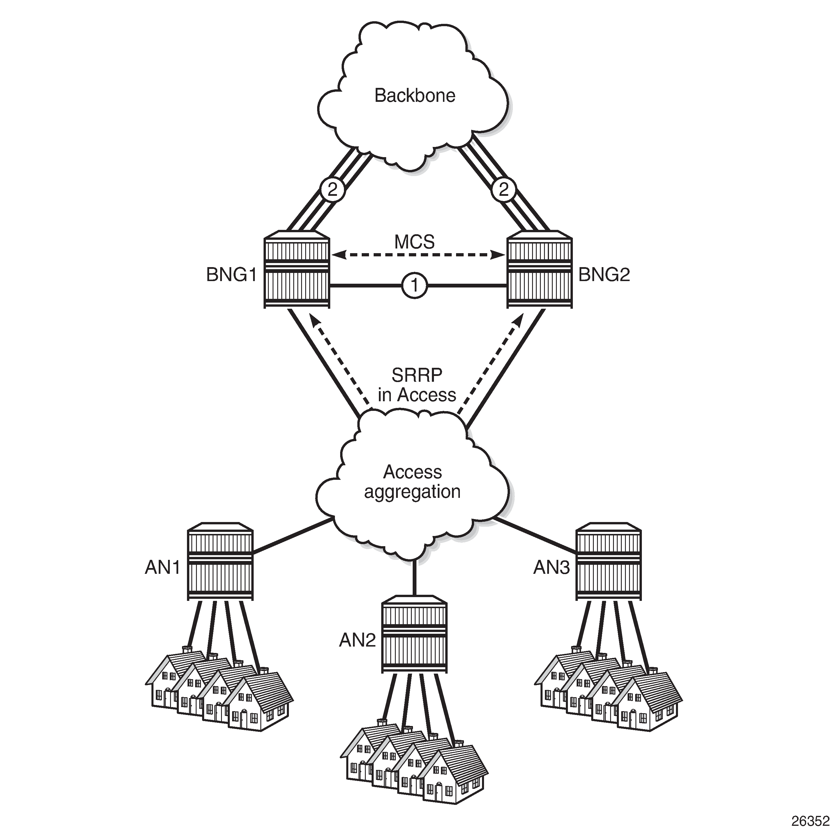
General Redundancy Model shows the general redundancy model, where clients connected to the Layer 2 access nodes AN1, AN2, and AN3 get their addresses from the DHCP servers located in BNG1 and BNG2, via relay agents that are also located in BNG1 and BNG2. Access network redundancy can be supported through the Subscriber Routed Redundancy protocol (SRRP) or through Multi Chassis Link Aggregation (MC-LAG) in combination with SRRP.
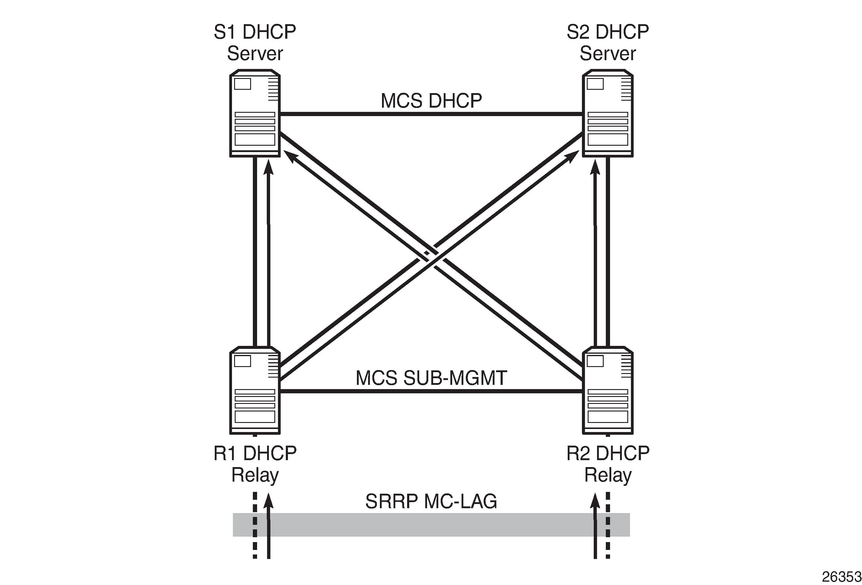
DHCP Relay Agent and Server Redundancy Model shows the DHCP relay agent and server redundancy model, where the DHCP relay agents R1 and R2 and the DHCP servers S1 and S2 are situated in different nodes in the network. DHCP requests received from the access network are relayed onto S1 and S2 via R1 and R2. MCS is used for synchronizing the lease database between servers S1 and S2. MCS can also be used for synchronizing the subscriber management information between R1 and R2, but that is out of the scope of this chapter.
MCS typically runs over a direct link connecting the two peers of a pair (scenario 1 in General Redundancy Model), but can also run over backbone links if no direct link is present (scenario 2 in General Redundancy Model). Regardless of the scenario, this link is referred to as the intercommunication link (ICL), and it should be well protected with multiple underlying physical paths.
DHCP server failover relies on the detection of a failure of the ICL. This link should be disjoint from the access links toward the DHCP clients.
DHCP server failover requires the nodes of a failover pair to have their date and time synchronized. This is commonly implemented using the network time protocol (NTP).
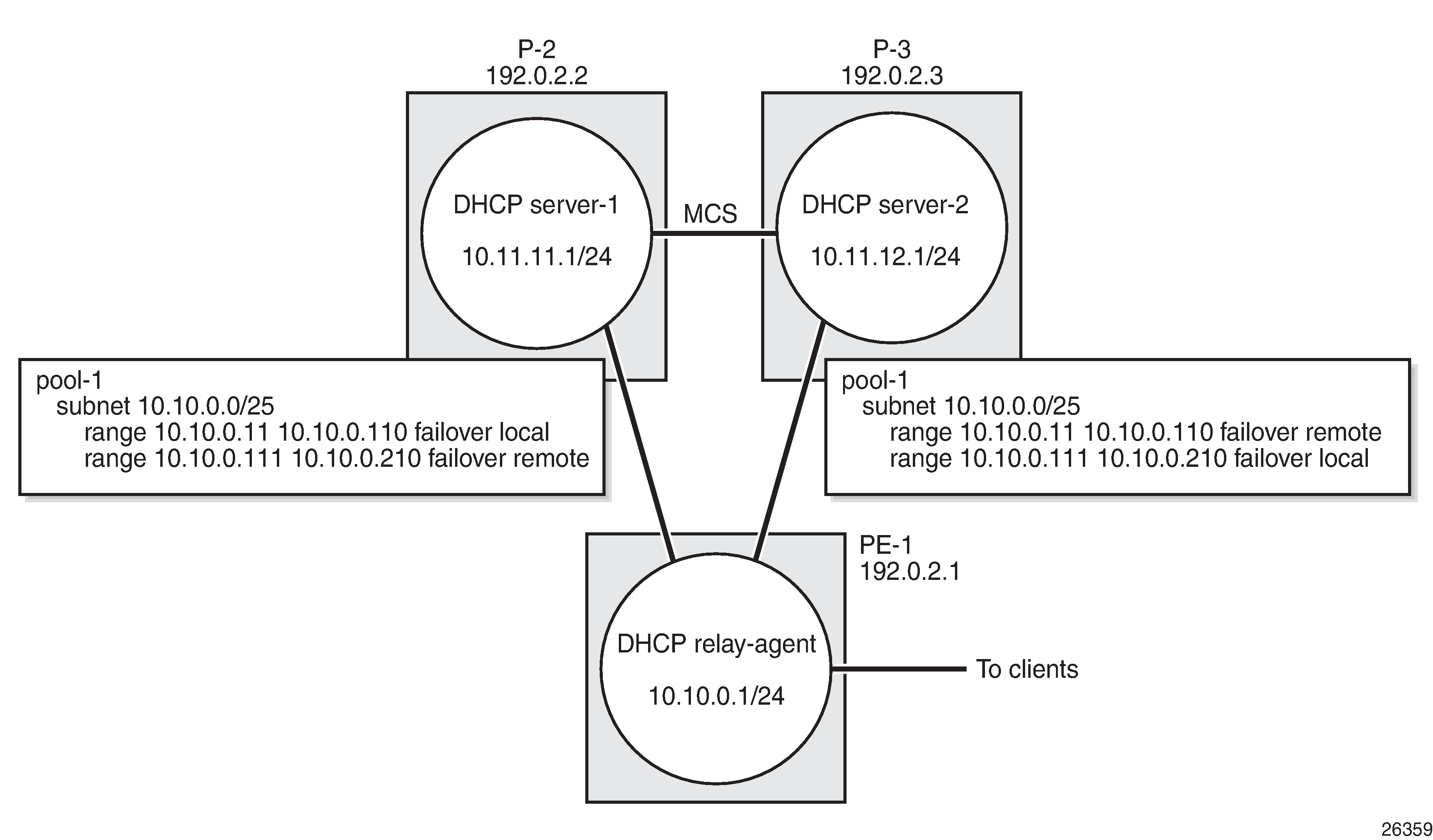
In the configuration section of this chapter, the local-remote deployment model is used, using a single relay agent and two DHCPv4 servers.
For basic DHCPv4 server configuration, see the DHCPv4 Server Basics chapter.
DHCP Server Failover and Address Management
For DHCP servers to support failover, the redundant servers need to share a set of subnets and address ranges so that one can take the role of the other in case of a failure, at the same time avoiding double allocations.
Following models are supported to achieve these requirements; see Access-Driven and Local-Remote Model:
access-driven model
local-remote model
An unsupported local-local model is similar to the access-driven model. They behave the same in terms of their failover, but different in terms of error handling; the local-local model can emit erroneous traps, whereas the access-driven model does not.
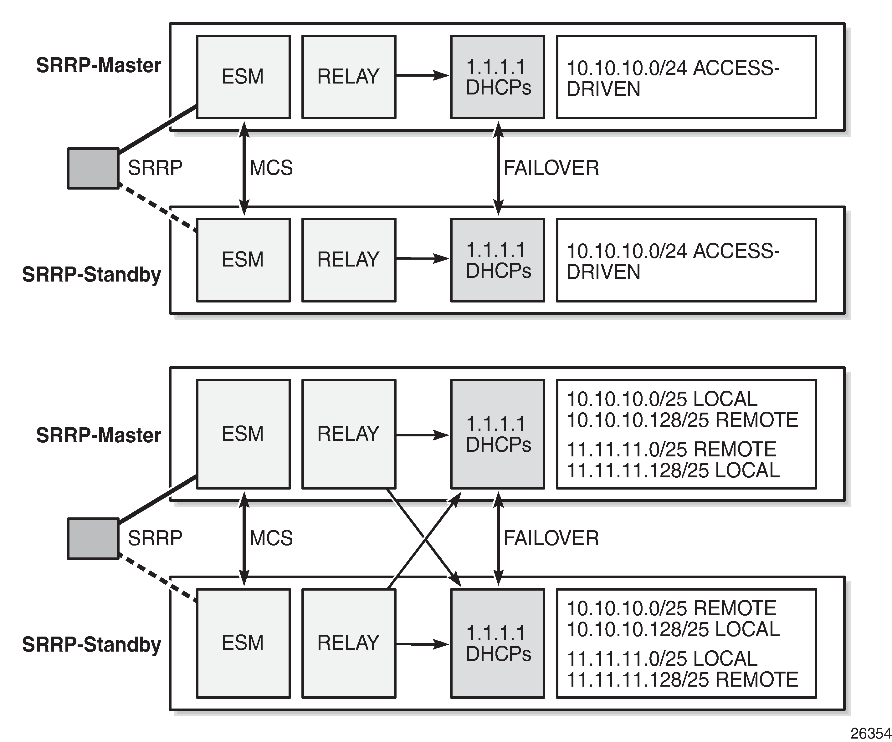
In the access-driven model, the address ranges on both DHCP servers are defined as access-driven. As for the topology, the relay agents are configured to relay the messages to and from one server only, and Nokia recommends that both DHCP servers use the same interface address. This can be achieved by hosting the ESM, relay, and DHCP server functionalities in the same router.
In the local-remote model, address ranges declared as local on one peer must be declared as remote on the other peer, and vice versa. As for the topology, the relay agents are configured to relay the messages to and from both servers, and do not need to be hosted by the same routers as the DHCP servers.
Avoiding Double Allocations
To avoid double allocations in the access-driven model, only one path should be active out of the access network toward the relay agent and the accompanying DHCP server. This is achieved through SRRP or MC-LAG in combination with SRRP in the access network. The relay agent must relay the messages to and from one server only, so this model is effectively an active-standby model.
To avoid double allocations in the local-remote model, where two paths from the access network to the DCHP servers exist and where two DHCP servers work in parallel, the following rules apply:
Addresses from the local (and access-driven) ranges can always be allocated, even when there is a communication failure between the peer servers, or when the peer server is down.
Addresses from remote ranges should only be allocated when the peer server is down.
When the ICL between the peers fails, so that the DHCP servers become isolated from each other, new clients connecting are allocated addresses from local (or access-driven) address ranges only. Because the ranges are declared as local on one peer, and remote on the other, without any overlap, there is no risk of double allocations. Because of the ICL failure, lease synchronization between the peers is not possible.
However, if the ICL failure lasts for an extended time, while both servers are up and running, then both peers consider their partner to be down. Both servers can start allocating addresses from their remote ranges, and there is a risk of assigning the same address to different clients. This situation must be avoided by ensuring that, when both peers are up, the ICL is also up.
Double allocations in a network is an indication of either two DHCP servers being isolated for too long or a misconfiguration in the network, and must never happen.
The DHCP Server Failover States and State Transitions section in this chapter provides a more extensive explanation.
Local-Remote Model – Active-Standby Configuration
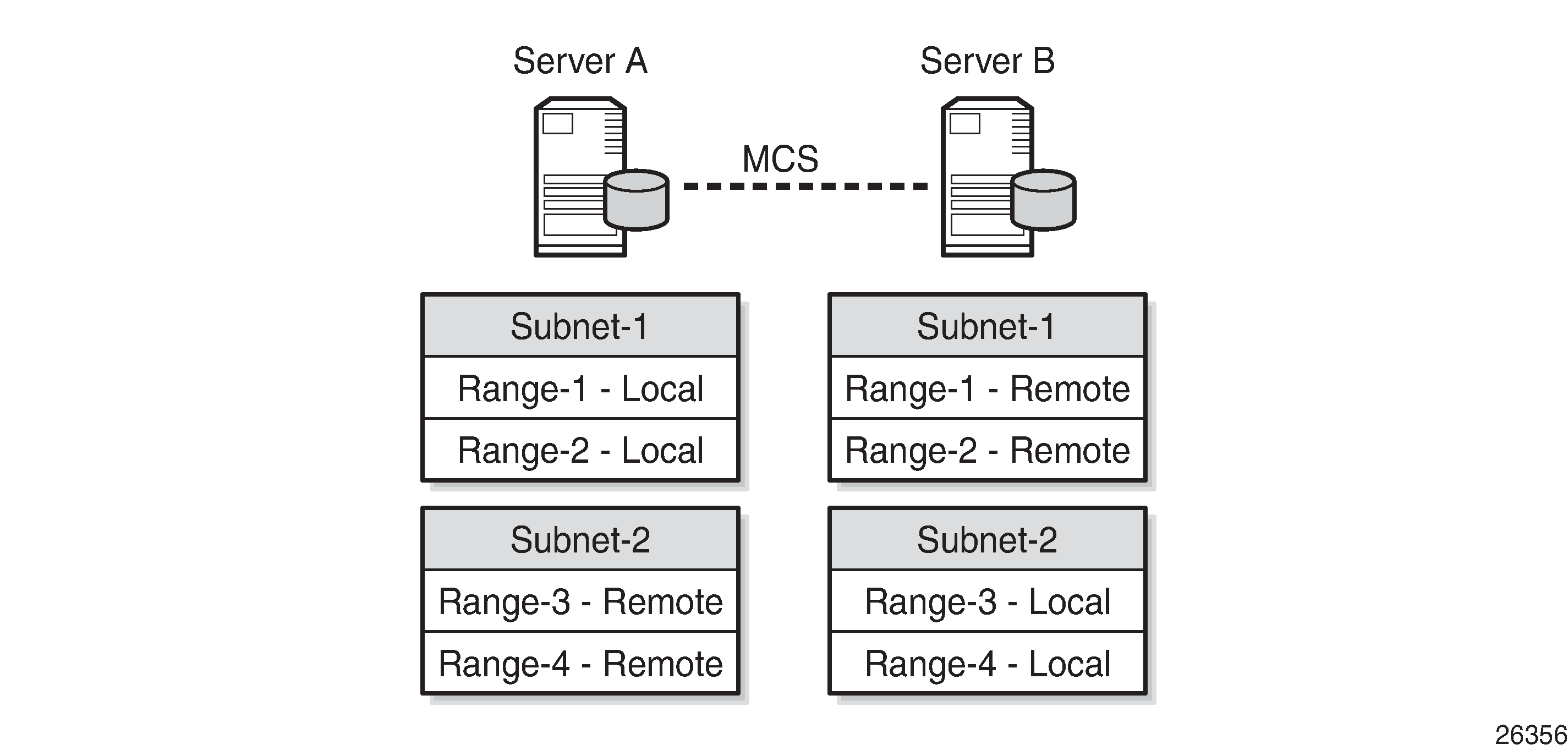
The first example of the local-remote model is an active-standby configuration; see Local-Remote Model – Active-Standby. All the ranges in all pools are declared local on DHCP server A (the active server), and remote on DHCP server B (the standby server).
Usually, leases are allocated by the active DHCP server. The standby DHCP server synchronizes with the active server through MCS, so it can take over all ranges of all subnets in case of a failure.
Even though server B also receives DHCP requests from clients, it will not allocate addresses from its subnets (because they are all declared remote) unless server A is down. Only when server A goes down does server B become active, and connects, rebinds, and renews clients.
Caution must be taken when deploying this model, because fast switchover requires ignoring the maximum client lead time (MCLT) on takeover and a low value for the partner down delay, as described later in this chapter.
Local-Remote Model – Load Sharing Configuration
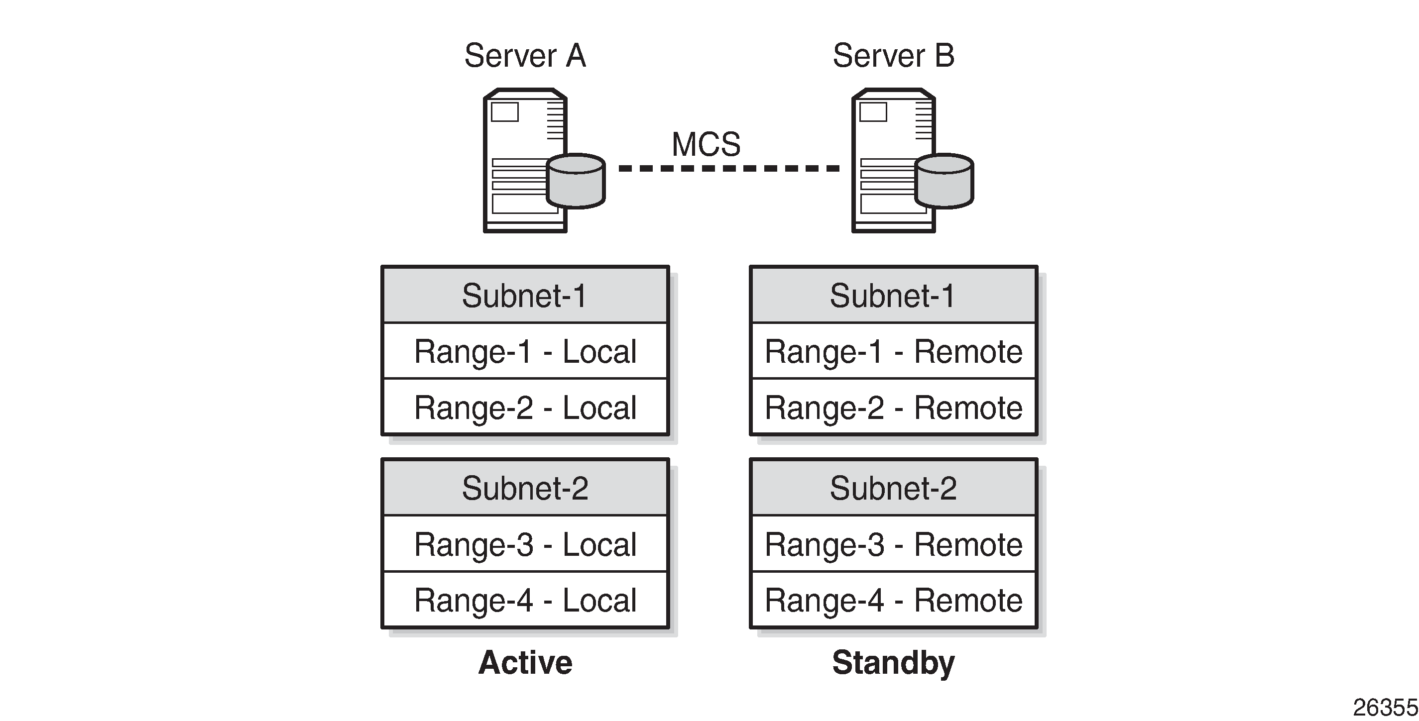
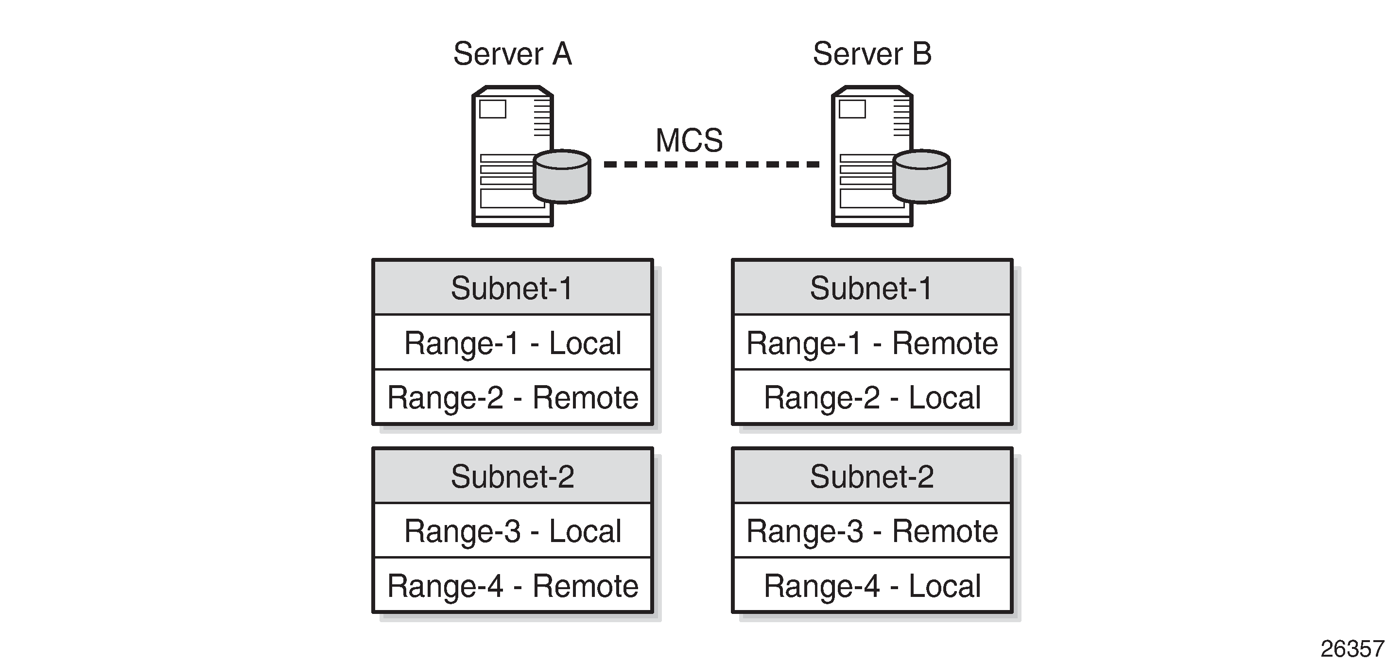
The second example of the local-remote model is a load sharing configuration; see Local-Remote Model – Subnet-Based Load Sharing. All subnet-1 ranges are declared local on server A, and remote on server B. For subnet-2, this is the opposite.
Usually, leases are allocated by both server A and server B. Server A is responsible for subnet-1, and thus manages addresses from subnet-1 (allocation, rebind, renew). At the same time, server B is responsible for subnet-2.
The standby DHCP server synchronizes with the active server through MCS, so it can take over all ranges of all subnets in case of a failure. Addresses from the remote ranges are managed only in case the server is in the partner down state.
A variant of this model is shown in Local-Remote Model – Range-Based Load Sharing, where a subnet is split into two ranges with the first range declared as local and the second range declared as a remote. The local/remote ratio can be chosen arbitrarily. For example, the ratio for subnet-1 can be defined as 80/20, meaning that for a range of 100 addresses, 80 addresses are available in the local range and 20 in the remote range. At the same time, a 50/50 ratio can be defined for subnet-2.
All these deployment models are supported for both IPv4 and IPv6, except for the model shown in Local-Remote Model – Range-Based Load Sharing, because IPv6 prefixes cannot be organized in ranges.
DHCP Server Failover States and State Transitions
When a DHCP server is configured and enabled for failover, SR OS maintains a failover state, see Failover State Transition Diagram. The failover state can have one of the following values:
INIT – the DHCP server is initializing and possibly recovering its leases from the persistency database (if persistency is enabled). In this state, the DHCP server does not respond to any unicast or broadcast messages.
STARTUP – the DHCP server recovers leases through MCS, and does not respond to any unicast or broadcast messages.
PRE-NORMAL – the DHCP server responds to unicast and broadcast messages for addresses in the local range, and to unicast messages for addresses in the remote range.
NORMAL – the DHCP server responds to local addresses only.
COMMUNICATIONS-INTERRUPTED – the DHCP server responds to local (and access-driven) addresses only, and operator intervention is required. In the remainder of this chapter, this state is abbreviated as COMM-INT.
PARTNER-DOWN – the DHCP server responds to local and remote ranges.
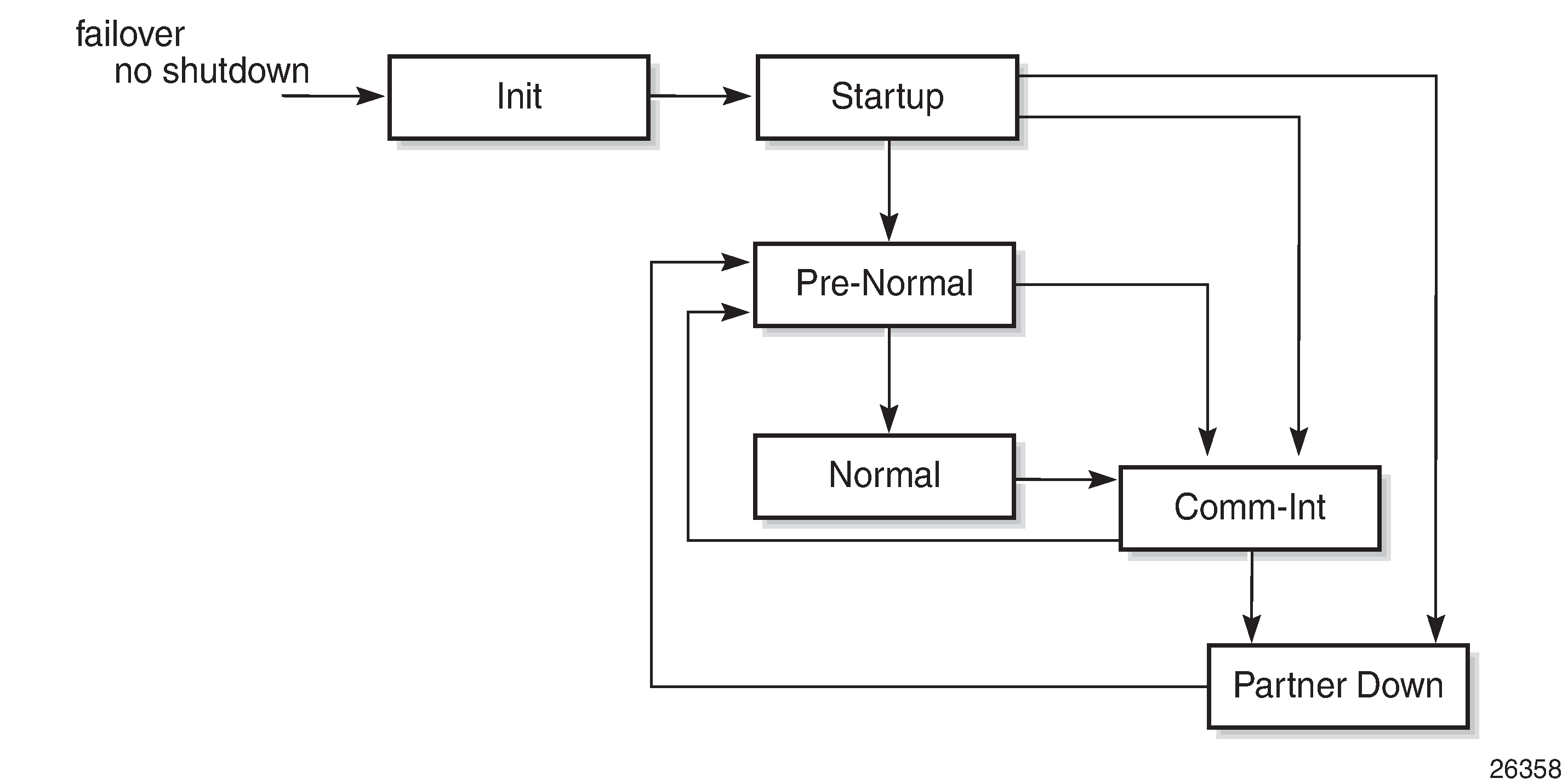
Enabling failover (no shutdown) triggers the change to the INIT failover state.
The INIT state is used while the DHCP server is recovering its lease database from persistency files when persistency applies. When recovery is completed, the failover state transitions to STARTUP. When persistency does not apply, the failover state transitions immediately to STARTUP.
When entering the STARTUP state, the startup-wait-timer is started to supervise the TCP connection setup to the MCS peer. If this timer expires and the connection is still not established, MCS communication has failed, and the failover state changes to COMM-INT. MCS recovery starts automatically if the TCP connection is established. When MCS recovery finishes, the failover state is changed to PRE-NORMAL. However, if an MCS state-record indicates that the failover state was PARTNER-DOWN before a reboot, the failover state is set to PARTNER-DOWN immediately.
The DHCP server will not respond to any DHCP messages while in the INIT or STARTUP state.
When the PRE-NORMAL state is reached at power on or reboot (so the previous failover state was STARTUP), the system immediately changes the failover state to NORMAL.
In the NORMAL state, the DHCP server manages the addresses from the local (and access-driven) address ranges. In parallel, MCS keeps the DHCP lease states between the peers synchronized. If an MCS no-sync event is received, the failover state changes to COMM-INT.
Because MCS cannot determine whether a server is down or a server is not reachable because of an ICL failure, an operator must intervene when the COMM-INT state is reached. If no operator intervenes for an extended period of time (defined by the partner-down-delay, default 23h 59m 59s), the failover state changes to PARTNER-DOWN.
This is not a problem if the DHCP peer is down; for example, because of a power failure. The active DHCP server starts managing the addresses from the local and the remote address ranges. When the failing DHCP peer is up and running again, it gets to the NORMAL state through the process previously described.
The situation where two DHCP peers are isolated and running independent of each other, so that both are in the PARTNER-DOWN state, must be avoided. It would lead to double allocations, where both servers assign the same addresses to different clients, which is service disrupting to the users involved. Potential duplicates are resolved when the MCLT timer expires, and both peers are synchronized again.
Getting into the COMM-INT status is not service affecting, but should be avoided because DHCP lease synchronization fails. Operators must prevent both DHCP servers getting into the PARTNER-DOWN state, and the time to take corrective actions is bound by the partner-down-delay. If the partner-down-delay is not sufficiently large, ensure that one of the peer DHCP servers is not reachable by any of the clients anymore; for example, by shutting down or removing power from that server.
When in either the COMM-INT or PARTNER-DOWN state, and an MCS sync-event is received because the ICL becomes active again, the DHCP server moves to the PRE-NORMAL state, and starts the pre-normal-timer, which is initialized to the MCLT value, described in the next section.
In the PRE-NORMAL state, the DHCP server recovers the remote leases through MCS. While in this state, the DHCP server will respond to unicast and broadcast DHCP messages from the local ranges, and to unicast DHCP messages from the remote range. Recovery will be finished before the pre-normal timer expires, after which the failover state returns to NORMAL.
Maximum Client Lead Time
When failover does not apply, the DHCP server provides lease durations as defined in the pool or subnet definitions. When a client explicitly requests a lease duration, the server checks and validates the requested lease duration, potentially changing the requested lease duration to match the boundaries.
Regardless of the failover deployment model, it is important that DHCP servers can only allocate or extend a lease for a limited amount of time beyond the lease time known by its peer. The maximum client lead time (MCLT) defines the maximum time that one server can extend the lease for a client’s binding, beyond the time known by the partner server, and is a safeguard against potential double allocations.
Nokia recommends using the same value for the MCLT on both partners of a failover pair. If they are different, the larger value is used. The default MCLT value is 10 min.
In the NORMAL state, clients initially get a lease time equal to the MCLT time. Over time, when renewing and rebinding, the allocated lease times are gradually increased to:
the requested lease times if they are within the configured bounds
the configured lease timer value
See the Lease Time Synchronization chapter in the 7450 ESS, 7750 SR, and VSR Triple Play Service Delivery Architecture Guide for examples.
In the COMM-INT state, lease durations for existing leases are gradually decreased on renewal and rebinding, down to a minimum value defined by the MCLT. New clients are provided lease times equal to the MCLT.
When the DHCP server returns to the NORMAL state, lease durations start increasing again if clients renew and rebind.
Commands Controlling Failover and Failover State
Commands controlling failover are available at the DHCP server level, or at the pool level, in the base router and in a VPRN context.
These commands are grouped in the failover context:
peer <ip-address> tag <sync-tag>
ignore-mclt-on-takeover
maximum-client-lead-time
partner-down-delay
startup-wait-time
The peer address is the IPv4 or IPv6 address of the DHCP failover peer, and is accompanied by a string of up to 32 characters, which serves as the sync-tag. This sync-tag must be the same on both peers.
The use of the other parameters is explained in the DHCP Server Failover States and State Transitions and Maximum Client Lead Time sections of this chapter.
A tools command is available, forcing the failover state to PARTNER-DOWN, and should be used with caution:
*A:P-2# tree flat | match tools | match force-partner
tools perform router dhcp local-dhcp-server failover force-partner-down
tools perform router dhcp local-dhcp-server pool failover force-partner-down
tools perform router dhcp6 local-dhcp-server failover force-partner-down
tools perform router dhcp6 local-dhcp-server pool failover force-partner-down
*A:P-2#
Configuration
Starting a DHCP server in an SR OS environment requires following steps:
Configure the DHCP server.
Configure the interfaces for the DHCP server to listen on.
Configure one or more relay agents.
The baseline configuration used in this chapter is shown in VPRN-1 Service Configuration, and relies on the relay agent to relay DHCP messages to and from both DHCP servers.
The example scenario uses DHCP clients only.
Configure Multi-Chassis Synchronization
MCS must be configured before configuring failover, because the DHCP lease state database is to be synchronized between the failover peers. Therefore, P-2 points to P-3, and vice-versa, as follows:
# P-2
configure
    redundancy
        multi-chassis
            peer 192.0.2.3 create
                sync
                    local-dhcp-server
                    no shutdown
                exit
                no shutdown
            exit
        exit
    exit
exit
# P-3
configure
    redundancy
        multi-chassis
            peer 192.0.2.2 create
                sync
                    local-dhcp-server
                    no shutdown
                exit
                no shutdown
            exit
        exit
    exit
exit
For MCS and failover to work, the clocks of the servers must be aligned, which is achieved through NTP. Configuration of NTP is beyond the scope of this chapter.
Configure common DHCP subnets
The 10.10.0.0/24 subnet is shared by P-2 and P-3. The [11-110] range is declared local to P-2 and remote to P-3. The [111-210] range is declared remote to P-2 and local to P-3, as follows:
# P-2
configure
    service
        vprn 1 customer 1 create
            dhcp
                local-dhcp-server "dhcp-1" create
                    use-gi-address scope pool
                    pool "pool-1" create
                        options
                            dns-server 1.1.1.1 1.1.2.2
                            lease-time min 20
                        exit
                        subnet 10.10.0.0/24 create
                            options
                                subnet-mask 255.255.255.0
                                default-router 10.10.0.1
                            exit
                            address-range 10.10.0.11 10.10.0.110 failover local
                            address-range 10.10.0.111 10.10.0.210 failover remote
                        exit
                    exit
The subnet and pool definitions on P-3 are as follows:
# P-3
configure
    service
        vprn 1 customer 1 create
            dhcp
                local-dhcp-server "dhcp-2" create
                    use-gi-address scope pool
                    pool "pool-1" create
                        options
                            dns-server 1.1.1.1 1.1.2.2
                            lease-time min 20
                        exit
                        subnet 10.10.0.0/24 create
                            options
                                subnet-mask 255.255.255.0
                                default-router 10.10.0.1
                            exit
                            address-range 10.10.0.11 10.10.0.110 failover remote
                            address-range 10.10.0.111 10.10.0.210 failover local
                        exit
                    exit
Configure Failover
P-2’s failover configuration for this example is as follows:
# P-2
configure
    service
        vprn 1 customer 1 create
            dhcp
                local-dhcp-server "dhcp-1" create
                    failover
                        peer 192.0.2.3 tag "mytag"
                        maximum-client-lead-time min 12
                        no shutdown
                    exit
                    no shutdown
                exit
            exit
P-3’s failover configuration for this example is as follows:
# P-3
configure
    service
        vprn 1 customer 1 create
            dhcp
                local-dhcp-server "dhcp-2" create
                    failover
                        peer 192.0.2.2 tag "mytag"
                        maximum-client-lead-time min 12
                        no shutdown
                    exit
                    no shutdown
                exit
            exit
Configure the Relay Agent
The DHCP relay agent for service VPRN 1 on PE-1 relays the DHCP messages to and from servers 10.11.11.1 and 10.11.12.1, as follows:
# PE-1
configure
    service
        vprn 1 customer 1 create
            route-distinguisher 64496:1
            auto-bind-tunnel
                resolution-filter
                    ldp
                exit
                resolution filter
            exit
            vrf-target target:64496:1
            subscriber-interface "int-SUB1" create
                address 10.10.0.1/24
                group-interface "int-GRP1" create
                    arp-populate
                    dhcp
                        option
                            action replace
                            circuit-id
                            no remote-id
                        exit
                        server 10.11.11.1 10.11.12.1
                        lease-populate 100
                        client-applications dhcp ppp
                        gi-address 10.10.0.1
                        no shutdown
                    exit
                    sap 1/1/1:1 create
                        sub-sla-mgmt
                            ---snip---
                        exit
                    exit
                exit
            exit
Debug and Troubleshooting
The following configuration enables debugging for DHCP server dhcp-1 on VPRN 1 on both P-2 and P-3:
debug
    router "1"
        local-dhcp-server "dhcp-1"
            detail-level medium
            mode egr-ingr-and-dropped
        exit
    exit
exit
To ensure that the debug output is sent to a session, the following additional configuration is needed:
configure
    log
        log-id 1
            from debug-trace
            to session
            no shutdown
        exit
    exit
exit
Operation and Verification
The following command shows all DHCP servers for VPRN 1. The DHCP server names are listed together with their administrative state.
*A:P-2# show router 1 dhcp servers all
==================================================================
Overview of DHCP Servers
==================================================================
Active Leases:      2
Maximum Leases:     159744
Router              Server                           Admin State
------------------------------------------------------------------
Service: 1          dhcp-1                           inService
==================================================================
*A:P-2#
The following command shows the DHCP server summary for server dhcp-1. The parameters related to failover are shown in bold. The first block applies to the entire DHCP server of dhcp-1, the second block is specific to pool-1.
*A:P-2# show router 1 dhcp local-dhcp-server "dhcp-1" summary
===============================================================================
DHCP server dhcp-1  router 1
===============================================================================
Admin State            : inService
Operational State      : inService
Persistency State      : shutdown
User Data Base         : N/A
Use gateway IP address : enabled (scope pool)
Use pool from client   : disabled
Send force-renewals    : disabled
Creation Origin        : manual
Lease Hold Time        : 0h0m0s
Lease Hold Time For    : N/A
User-ident             : mac-circuit-id

Failover Admin State   : inService
Failover Oper State    : normal
Failover Persist Key   : N/A
Administrative MCLT    : 0h12m0s
Operational MCLT       : 0h12m0s
Startup wait time      : 0h2m0s
Partner down delay     : 23h59m59s
  Ignore MCLT          : disabled

-------------------------------------------------------------------------------
Pool name : pool-1
-------------------------------------------------------------------------------
Failover Admin State   : outOfService
Failover Oper State    : shutdown
Failover Persist Key   : N/A
Administrative MCLT    : 0h10m0s
Operational MCLT       : 0h10m0s
Startup wait time      : 0h2m0s
Partner down delay     : 23h59m59s
  Ignore MCLT          : disabled
-------------------------------------------------------------------------------
Subnet                 Free     %    Stable   Declined Offered  Rem-pend Drain
-------------------------------------------------------------------------------
10.10.0.0/24       (L) 100      100% 0        0        0        0        N
                   (R) N/A           0        N/A      N/A      N/A      N
Totals for pool        100      100% 0        0        0        0
-------------------------------------------------------------------------------

Totals for server      100      100% 0        0        0        0

-------------------------------------------------------------------------------
Interface associations
Interface                        Admin
-------------------------------------------------------------------------------

-------------------------------------------------------------------------------
Local Address Assignment associations
Group interface                  Admin
-------------------------------------------------------------------------------
-------------------------------------------------------------------------------
No associations found
===============================================================================
*A:P-2#
With the DHCP server dhcp-1 on P-2 in the NORMAL failover state, a user connecting gets an address allocated from a local pool, with the initial lease time set to the MCLT, as follows:
1 2017/02/02 15:18:23.20 CET MINOR: DEBUG #2001 vprn1 DHCP server
"DHCP server:  dhcp-1
Rx DHCP Discover

   ciaddr: 0.0.0.0           yiaddr: 0.0.0.0
   siaddr: 0.0.0.0           giaddr: 10.10.0.1
   chaddr: 00:00:00:01:01:01    xid: 0x21

   DHCP options:
   [82] Relay agent information: len = 25
      [1] Circuit-id: PE-1|1|int-GRP1|1/1/1:1
   [53] Message type: Discover
   [255] End
"

2 2017/02/02 15:18:23.20 CET MINOR: DEBUG #2001 vprn1 DHCP server
"DHCP server:  dhcp-1
lease added for 10.10.0.12 state=offer
"

3 2017/02/02 15:18:23.20 CET MINOR: DEBUG #2001 vprn1 DHCP server
"DHCP server:  dhcp-1
Tx DHCP Offer to relay agent at 10.10.0.1 vrId=2

   ciaddr: 0.0.0.0           yiaddr: 10.10.0.12
   siaddr: 10.11.11.1        giaddr: 10.10.0.1
   chaddr: 00:00:00:01:01:01    xid: 0x21

   DHCP options:
   [82] Relay agent information: len = 25
      [1] Circuit-id: PE-1|1|int-GRP1|1/1/1:1
   [53] Message type: Offer
   [54] DHCP server addr: 10.11.11.1
   [51] Lease time: 720
   [1] Subnet mask: 255.255.255.0
   [3] Router: 10.10.0.1
   [6] Domain name server: length = 8
             1.1.1.1
             1.1.2.2
   [255] End
"

4 2017/02/02 15:18:23.22 CET MINOR: DEBUG #2001 vprn1 DHCP server
"DHCP server:  dhcp-1
Rx DHCP Request
   ciaddr: 0.0.0.0           yiaddr: 0.0.0.0
   siaddr: 0.0.0.0           giaddr: 10.10.0.1
   chaddr: 00:00:00:01:01:01    xid: 0x21

   DHCP options:
   [82] Relay agent information: len = 25
      [1] Circuit-id: PE-1|1|int-GRP1|1/1/1:1
   [53] Message type: Request
   [50] Requested IP addr: 10.10.0.12
   [54] DHCP server addr: 10.11.11.1
   [255] End
"

5 2017/02/02 15:18:23.22 CET MINOR: DEBUG #2001 vprn1 DHCP server
"DHCP server:  dhcp-1
lease update for 10.10.0.12 state=stable
"

6 2017/02/02 15:18:23.22 CET MINOR: DEBUG #2001 vprn1 DHCP server
"DHCP server:  dhcp-1
Tx DHCP Ack to relay agent at 10.10.0.1 vrId=2

   ciaddr: 0.0.0.0           yiaddr: 10.10.0.12
   siaddr: 10.11.11.1        giaddr: 10.10.0.1
   chaddr: 00:00:00:01:01:01    xid: 0x21

   DHCP options:
   [82] Relay agent information: len = 25
      [1] Circuit-id: PE-1|1|int-GRP1|1/1/1:1
   [53] Message type: Ack
   [54] DHCP server addr: 10.11.11.1
   [51] Lease time: 720
   [1] Subnet mask: 255.255.255.0
   [3] Router: 10.10.0.1
   [6] Domain name server: length = 8
             1.1.1.1
             1.1.2.2
   [255] End
"
Server dhcp-1 on P-3 also offers a lease, but the client does not accept that offer so that lease is deleted. Because the client acknowledges the lease allocated by P-2, that lease is synchronized through MCS, as follows:
2 2017/02/02 15:18:23.68 CET MINOR: DEBUG #2001 vprn1 DHCP server
"DHCP server:  dhcp-1
Rx DHCP Discover

   ciaddr: 0.0.0.0           yiaddr: 0.0.0.0
   siaddr: 0.0.0.0           giaddr: 10.10.0.1
   chaddr: 00:00:00:01:01:01    xid: 0x21

   DHCP options:
   [82] Relay agent information: len = 25
      [1] Circuit-id: PE-1|1|int-GRP1|1/1/1:1
   [53] Message type: Discover
   [255] End
"

3 2017/02/02 15:18:23.68 CET MINOR: DEBUG #2001 vprn1 DHCP server
"DHCP server:  dhcp-1
lease added for 10.10.0.112 state=offer
"

4 2017/02/02 15:18:23.68 CET MINOR: DEBUG #2001 vprn1 DHCP server
"DHCP server:  dhcp-1
Tx DHCP Offer to relay agent at 10.10.0.1 vrId=2

   ciaddr: 0.0.0.0           yiaddr: 10.10.0.112
   siaddr: 10.11.12.1        giaddr: 10.10.0.1
   chaddr: 00:00:00:01:01:01    xid: 0x21

   DHCP options:
   [82] Relay agent information: len = 25
      [1] Circuit-id: PE-1|1|int-GRP1|1/1/1:1
   [53] Message type: Offer
   [54] DHCP server addr: 10.11.12.1
   [51] Lease time: 720
   [1] Subnet mask: 255.255.255.0
   [3] Router: 10.10.0.1
   [6] Domain name server: length = 8
             1.1.1.1
             1.1.2.2
   [255] End
"

5 2017/02/02 15:18:23.70 CET MINOR: DEBUG #2001 vprn1 DHCP server
"DHCP server:  dhcp-1
Rx DHCP Request

   ciaddr: 0.0.0.0           yiaddr: 0.0.0.0
   siaddr: 0.0.0.0           giaddr: 10.10.0.1
   chaddr: 00:00:00:01:01:01    xid: 0x21

   DHCP options:
   [82] Relay agent information: len = 25
      [1] Circuit-id: PE-1|1|int-GRP1|1/1/1:1
   [53] Message type: Request
   [50] Requested IP addr: 10.10.0.12
   [54] DHCP server addr: 10.11.11.1
   [255] End
"

6 2017/02/02 15:18:23.70 CET MINOR: DEBUG #2001 vprn1 DHCP server
"DHCP server:  dhcp-1
dropped: Client didn't accept our offer, deleting lease 10.10.0.112
"

7 2017/02/02 15:18:23.70 CET MINOR: DEBUG #2001 vprn1 DHCP server
"DHCP server:  dhcp-1
lease added for 10.10.0.12 state=stable
"
With one user connected, check the leases on P-2 and P-3, as follows:
*A:P-2# show router 1 dhcp local-dhcp-server "dhcp-1" leases

===============================================================================
Leases for DHCP server dhcp-1 router 1
===============================================================================
IP Address      Lease State       Mac Address       Remaining   Clnt  Fail
  PPP user name/Opt82 Circuit Id                    LifeTime    Type  Ctrl
  User-db/Sticky-lease Hostname
-------------------------------------------------------------------------------
10.10.0.12      stable            00:00:00:01:01:01 0h33m31s    dhcp  local
  PE-1|1|int-GRP1|1/1/1:1
-------------------------------------------------------------------------------
1 leases found
===============================================================================
*A:P-2#
*A:P-3# show router 1 dhcp local-dhcp-server "dhcp-1" leases

===============================================================================
Leases for DHCP server dhcp-1 router 1
===============================================================================
IP Address      Lease State       Mac Address       Remaining   Clnt  Fail
  PPP user name/Opt82 Circuit Id                    LifeTime    Type  Ctrl
  User-db/Sticky-lease Hostname
-------------------------------------------------------------------------------
10.10.0.12      stable            00:00:00:01:01:01 0h33m5s     dhcp  remote
  PE-1|1|int-GRP1|1/1/1:1
-------------------------------------------------------------------------------
1 leases found
===============================================================================
*A:P-3#
For lease 10.10.0.12, failover control is local on P-2 and remote on P-3, and this matches the pool definitions from the beginning of the configuration section.
The details for the 10.10.0.12 lease can be shown with the following command. The remaining potential expiration time is ahead of the remaining lifetime, as follows:
*A:P-2# show router 1 dhcp local-dhcp-server "dhcp-1" leases 10.10.0.12 detail

===============================================================================
Lease for DHCP server dhcp-1 router 1
===============================================================================
IP-address                   : 10.10.0.12
Lease-state                  : stable
Lease started                : 2017/02/02 15:18:23
Last renew                   : N/A
Remaining LifeTime           : 0h8m24s
Remaining Potential Exp. Time: 0h32m24s
Sticky-lease Host Name       : N/A
MAC address                  : 00:00:00:01:01:01
Xid                          : 0x21
Failover Control             : local
Client Type                  : dhcp
User-db Host Name            : N/A
User-db Address Type         : N/A
Persistence Key              : N/A
Opt82 Hex Dump               : (length=27)
                             : 52 19 01 17 50 45 2d 31 7c 31 7c 69 6e 74 2d 47
                             : 52 50 31 7c 31 2f 31 2f 31 3a 31
Opt82 Circuit Id             : PE-1|1|int-GRP1|1/1/1:1
Opt82 Remote Id              :
Opt82 Subscr Id              :
Opt82 VS System              :
Opt82 VS Clnt MAC            :
Opt82 VS Service             :
Opt82 VS SAP                 :
Opt82 VS String              :
Lease Remaining Hold Time    : 0h0m0s
===============================================================================
*A:P-2#
On renewal of this lease, the offered lease time is increased to the configured lease time, as follows:
7 2017/02/02 15:24:24.10 CET MINOR: DEBUG #2001 vprn1 DHCP server
"DHCP server:  dhcp-1
Rx DHCP Request

   ciaddr: 10.10.0.12        yiaddr: 0.0.0.0
   siaddr: 0.0.0.0           giaddr: 0.0.0.0
   chaddr: 00:00:00:01:01:01    xid: 0x21

   DHCP options:
   [82] Relay agent information: len = 25
      [1] Circuit-id: PE-1|1|int-GRP1|1/1/1:1
   [53] Message type: Request
   [255] End
"

8 2017/02/02 15:24:24.10 CET MINOR: DEBUG #2001 vprn1 DHCP server
"DHCP server:  dhcp-1
lease update for 10.10.0.12 state=stable
"

9 2017/02/02 15:24:24.10 CET MINOR: DEBUG #2001 vprn1 DHCP server
"DHCP server:  dhcp-1
Tx DHCP Ack to client at 10.10.0.12 vrId=2

   ciaddr: 10.10.0.12        yiaddr: 10.10.0.12
   siaddr: 10.11.11.1        giaddr: 0.0.0.0
   chaddr: 00:00:00:01:01:01    xid: 0x21

   DHCP options:
   [82] Relay agent information: len = 25
      [1] Circuit-id: PE-1|1|int-GRP1|1/1/1:1
   [53] Message type: Ack
   [54] DHCP server addr: 10.11.11.1
   [51] Lease time: 1800
   [1] Subnet mask: 255.255.255.0
   [3] Router: 10.10.0.1
   [6] Domain name server: length = 8
             1.1.1.1
             1.1.2.2
   [255] End
"
The remaining lifetime and the potential remaining expiration time are adjusted, as follows:
*A:P-2# show router 1 dhcp local-dhcp-server "dhcp-1" leases 10.10.0.12 detail

===============================================================================
Lease for DHCP server dhcp-1 router 1
===============================================================================
IP-address                   : 10.10.0.12
Lease-state                  : stable
Lease started                : 2017/02/02 15:18:23
Last renew                   : 2017/02/02 15:24:24
Remaining LifeTime           : 0h25m1s
Remaining Potential Exp. Time: 0h40m1s
Sticky-lease Host Name       : N/A
MAC address                  : 00:00:00:01:01:01
Xid                          : 0x21
Failover Control             : local
Client Type                  : dhcp
User-db Host Name            : N/A
User-db Address Type         : N/A
Persistence Key              : N/A
Opt82 Hex Dump               : (length=27)
                             : 52 19 01 17 50 45 2d 31 7c 31 7c 69 6e 74 2d 47
                             : 52 50 31 7c 31 2f 31 2f 31 3a 31
Opt82 Circuit Id             : PE-1|1|int-GRP1|1/1/1:1
Opt82 Remote Id              :
Opt82 Subscr Id              :
Opt82 VS System              :
Opt82 VS Clnt MAC            :
Opt82 VS Service             :
Opt82 VS SAP                 :
Opt82 VS String              :
Lease Remaining Hold Time    : 0h0m0s

===============================================================================
*A:P-2#
P-3 updates its lease database through MCS as users connect, disconnect, renew, or rebind their leases, as long as the ICL is uninterrupted and the failover state remains NORMAL, as follows:
9 2017/02/02 15:39:23.89 CET MINOR: DEBUG #2001 vprn1 DHCP server
"DHCP server:  dhcp-1
lease update for 10.10.0.12 state=stable
"

15 2017/02/02 15:39:41.22 CET MINOR: DEBUG #2001 vprn1 DHCP server
"DHCP server:  dhcp-1
lease added for 10.10.0.13 state=stable
"

16 2017/02/02 15:40:33.04 CET MINOR: DEBUG #2001 vprn1 DHCP server
"DHCP server:  dhcp-1
lease deleted for 10.10.0.13 (delete from peer)
A failure of the ICL is emulated by disabling failover for VPRN-1 on P-3, as follows:
*A:P-3# configure service vprn 1 dhcp local-dhcp-server "dhcp-1" failover shutdown
On P-3, the following debug messages appear:
28 2017/02/02 16:23:00.46 CET MINOR: DEBUG #2001 vprn1 DHCP server
"DHCP server:  dhcp-1
Failover oper state change from NORMAL to SHUTTING-DOWN
"

29 2017/02/02 16:23:00.46 CET MINOR: DEBUG #2001 vprn1 DHCP server
"DHCP server:  dhcp-1
remote lease deleted for 10.10.0.12 (failover shutdown)
"

30 2017/02/02 16:23:00.46 CET MINOR: DEBUG #2001 vprn1 DHCP server
"DHCP server:  dhcp-1
Failover oper state change from SHUTTING-DOWN to SHUTDOWN
"

31 2017/02/02 16:23:00.46 CET MINOR: DEBUG #2001 vprn1 DHCP server
"DHCP server:  dhcp-1
RX failover peer state COMMUNICATION-INTERRUPTED
"
On P-2, the following debug messages appear:
32 2017/02/02 16:23:00.45 CET MINOR: DEBUG #2001 vprn1 DHCP server
"DHCP server:  dhcp-1
RX failover peer state SHUTDOWN
"

33 2017/02/02 16:23:00.45 CET MINOR: DEBUG #2001 vprn1 DHCP server
"DHCP server:  dhcp-1
Failover oper state change from NORMAL to COMMUNICATION-INTERRUPTED
"
Displaying the DHCP server summary for VPRN-1 on P-2 again shows the failover operational state as noCommunication. ‟Time Left” indicates how much time is left before the failover state changes to the PARTNER-DOWN operational state if no action is taken for resolving the communication issue.
*A:P-2# show router 1 dhcp local-dhcp-server "dhcp-1" summary
===============================================================================
DHCP server dhcp-1  router 1
===============================================================================
Admin State            : inService
Operational State      : inService
Persistency State      : shutdown
User Data Base         : N/A
Use gateway IP address : enabled (scope pool)
Use pool from client   : disabled
Send force-renewals    : disabled
Creation Origin        : manual
Lease Hold Time        : 0h0m0s
Lease Hold Time For    : N/A
User-ident             : mac-circuit-id

Failover Admin State   : inService
Failover Oper State    : noCommunication
Failover Persist Key   : N/A
Time Left              : 23h56m15s before state transition
Administrative MCLT    : 0h12m0s
Operational MCLT       : 0h12m0s
Startup wait time      : 0h2m0s
Partner down delay     : 23h59m59s
  Ignore MCLT          : disabled

---snip---

===============================================================================
*A:P-2##
Check the status for lease 10.10.0.12 again, as follows.
*A:P-2# show router 1 dhcp local-dhcp-server "dhcp-1" leases 10.10.0.12 detail

===============================================================================
Lease for DHCP server dhcp-1 router 1
===============================================================================
IP-address                   : 10.10.0.12
Lease-state                  : stable
Lease started                : 2017/02/02 15:18:23
Last renew                   : 2017/02/02 16:24:24
Remaining LifeTime           : 0h23m35s
Remaining Potential Exp. Time: 0h23m35s
Sticky-lease Host Name       : N/A
MAC address                  : 00:00:00:01:01:01
Xid                          : 0x21
Failover Control             : local
Client Type                  : dhcp
User-db Host Name            : N/A
User-db Address Type         : N/A
Persistence Key              : N/A
Opt82 Hex Dump               : (length=27)
                             : 52 19 01 17 50 45 2d 31 7c 31 7c 69 6e 74 2d 47
                             : 52 50 31 7c 31 2f 31 2f 31 3a 31
Opt82 Circuit Id             : PE-1|1|int-GRP1|1/1/1:1
Opt82 Remote Id              :
Opt82 Subscr Id              :
Opt82 VS System              :
Opt82 VS Clnt MAC            :
Opt82 VS Service             :
Opt82 VS SAP                 :
Opt82 VS String              :
Lease Remaining Hold Time    : 0h0m0s

===============================================================================
*A:P-2#
New clients connecting are allocated addresses from the local address ranges on either P-2 or P-3, even when the server is in the COMM-INT failover state. In this example, both clients are allocated and acknowledged addresses by P-2, as follows:
*A:P-2# show router 1 dhcp local-dhcp-server "dhcp-1" leases

===============================================================================
Leases for DHCP server dhcp-1 router 1
===============================================================================
IP Address      Lease State       Mac Address       Remaining   Clnt  Fail
  PPP user name/Opt82 Circuit Id                    LifeTime    Type  Ctrl
  User-db/Sticky-lease Hostname
-------------------------------------------------------------------------------
10.10.0.12      stable            00:00:00:01:01:01 0h19m2s     dhcp  local
  PE-1|1|int-GRP1|1/1/1:1
10.10.0.14      stable            00:00:00:01:01:02 0h10m51s    dhcp  local
  PE-1|1|int-GRP1|1/1/1:1
-------------------------------------------------------------------------------
2 leases found
===============================================================================
*A:P-2#
Solving the communications issue is emulated by enabling failover for VPRN-1 on P-3 again:
*A:P-3# configure service vprn 1 dhcp local-dhcp-server "dhcp-1" failover no shutdown
The debug log on P-2 shows as follows:
49 2017/02/02 16:41:17.60 CET MINOR: DEBUG #2001 vprn1 DHCP server
"DHCP server:  dhcp-1
RX failover peer state NORMAL
"

50 2017/02/02 16:41:17.60 CET MINOR: DEBUG #2001 vprn1 DHCP server
"DHCP server:  dhcp-1
Failover oper state change from COMMUNICATION-INTERRUPTED to PRE-NORMAL
"
The debug log on P-3 shows as follows:
37 2017/02/02 16:41:17.60 CET MINOR: DEBUG #2001 vprn1 DHCP server
"DHCP server:  dhcp-1
Failover oper state change from SHUTDOWN to STARTUP
"

38 2017/02/02 16:41:17.60 CET MINOR: DEBUG #2001 vprn1 DHCP server
"DHCP server:  dhcp-1
Failover oper state change from STARTUP to PRE-NORMAL
"

39 2017/02/02 16:41:17.60 CET MINOR: DEBUG #2001 vprn1 DHCP server
"DHCP server:  dhcp-1
Failover oper state change from PRE-NORMAL to NORMAL
"

40 2017/02/02 16:41:17.60 CET MINOR: DEBUG #2001 vprn1 DHCP server
"DHCP server:  dhcp-1
lease added for 10.10.0.12 state=stable
"

41 2017/02/02 16:41:17.60 CET MINOR: DEBUG #2001 vprn1 DHCP server
"DHCP server:  dhcp-1
lease added for 10.10.0.14 state=stable
"

42 2017/02/02 16:41:17.60 CET MINOR: DEBUG #2001 vprn1 DHCP server
"DHCP server:  dhcp-1
RX failover peer state NORMAL
"
The leases allocated by P-2 are synchronized with peer P-3, so they are marked as remote leases, as follows:
*A:P-3# show router 1 dhcp local-dhcp-server "dhcp-1" leases

===============================================================================
Leases for DHCP server dhcp-1 router 1
===============================================================================
IP Address      Lease State       Mac Address       Remaining   Clnt  Fail
  PPP user name/Opt82 Circuit Id                    LifeTime    Type  Ctrl
  User-db/Sticky-lease Hostname
-------------------------------------------------------------------------------
10.10.0.12      stable            00:00:00:01:01:01 0h38m37s    dhcp  remote
  PE-1|1|int-GRP1|1/1/1:1
10.10.0.14      stable            00:00:00:01:01:02 0h31m57s    dhcp  remote
  PE-1|1|int-GRP1|1/1/1:1
-------------------------------------------------------------------------------
2 leases found
===============================================================================
*A:P-3#
Eventually, P-2’s failover state changes to NORMAL again, as follows:
57 2017/02/02 16:53:17.85 CET MINOR: DEBUG #2001 vprn1 DHCP server
"DHCP server:  dhcp-1
Failover oper state change from PRE-NORMAL to NORMAL
"
Conclusion
SR OS supports DHCP server redundancy with failover, providing ISPs the capabilities to offer DHCP service during a partial power loss or partial network outage.