ESM IPv4: Multicast with SRRP
This chapter describes ESM IPv4 multicast with SRRP configurations.
Topics in this chapter include:
Applicability
This chapter applies to SR OS routers, and was originally written for Release 11.0.R1. The CLI is updated to Release 15.0.R3. It covers multicast with Subscriber Routed Redundancy Protocol (SRRP) for IPoE and PPPoE subscribers.
Overview
Triple Play Service Delivery Architecture (TPSDA) has allowed operators to integrate High Speed Internet (HSI), voice, and video services within a single network. The goal of this chapter is to walk through the configuration of a redundant TPSDA multicast architecture and the configuration of multicast filters. The topics are divided into the following sections:
Enhanced Subscriber Management (ESM) multicast baseline configuration
IGMP configuration on ESM group interface
ESM IGMP-policy configuration
IPoE ESM multicast walkthrough
PPPoE ESM multicast walkthrough
IGMP Subscriber Router Redundancy Protocol (SRRP)
Multi-Chassis Synchronization (MCS) walkthrough
IGMP Debugging
IGMP Control Plane Filters
IGMP Data Plane Filters
The network topology displayed in Network Topology Overview shows a typical TPSDA setup. It consists of three 7750s and a single 7450. Two 7750s are configured as Broadband Network Gateways (BNGs) and the third 7750 is configured as a P router. The 7450 is used as an aggregation switch to aggregate all subscribers.
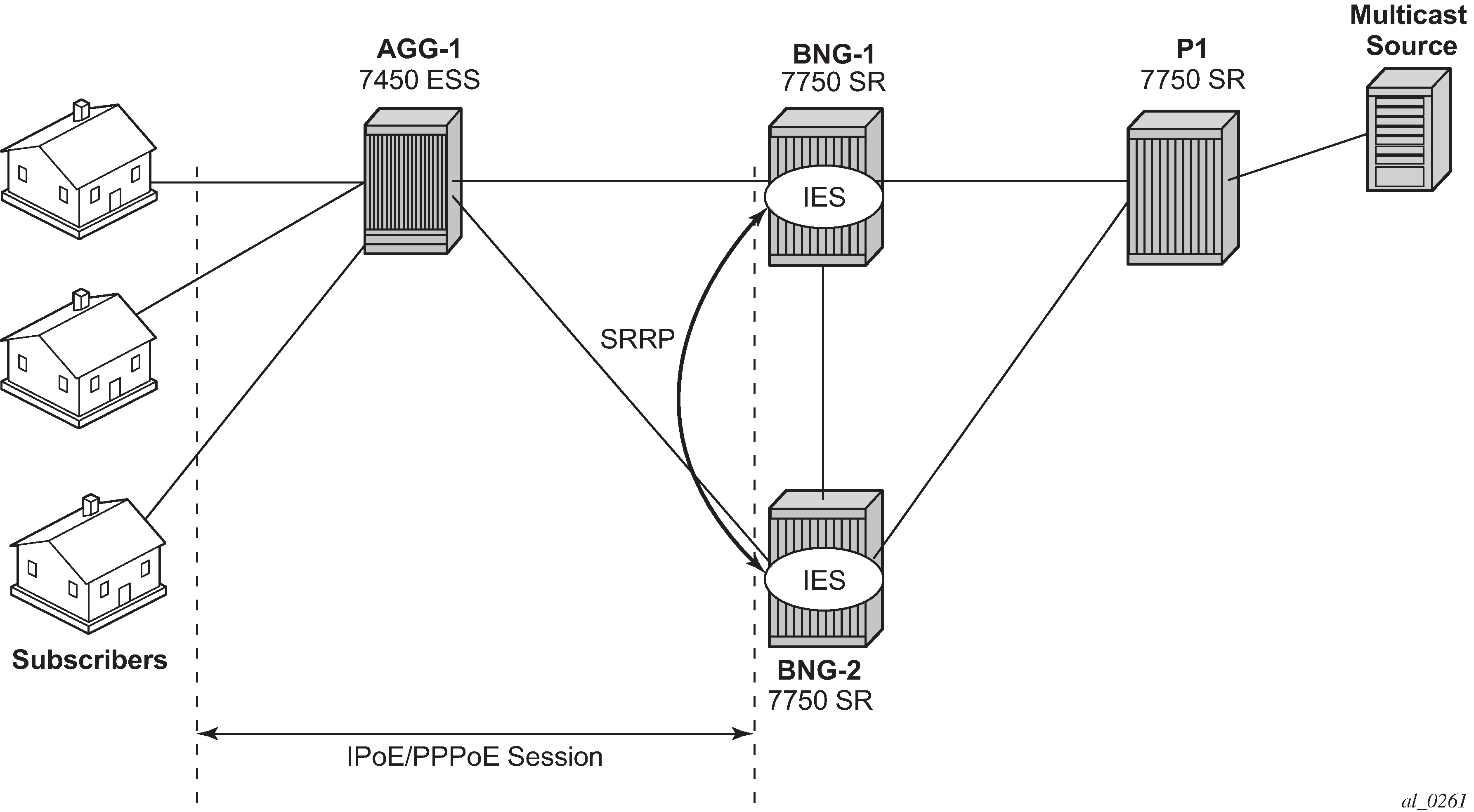
Both BNGs are configured with SRRP to provide redundancy. SRRP is only used for redundancy purposes. SRRP is not required for supporting multicast. The P router is connected to the multicast source and to the network side of both BNGs. The connections between the BNGs and the P router are also running PIM to provide multicast delivery. On the access side, the two BNGs are connected to an aggregation switch which aggregates the traffic originating from both PPPoE and IPoE subscribers. The BNGs are IGMP capable and will respond to subscribers’ IGMP requests.
There are two requirements to enable multicast delivery using ESM. First, the ESM group interface must have IGMP enabled. Second, the ESM subscribers must be configured with an IGMP-policy to receive multicast. When both requirements are met, the BNG will process the subscribers’ IGMP messages, otherwise, IGMP messages are simply ignored and dropped. All customer premise equipment (CPE) IGMP messages are aggregated via the 7450 and passed to the BNGs. Because the BNGs are running SRRP, the SRRP master is the only BNG processing and answering the IGMP messages. Protocol Independent Multicasting (PIM) is then used between the BNG and the P router to request the multicast stream. If PIM is successful in retrieving the multicast group, the multicast stream is forwarded toward the subscribers. This is the typical multicast delivery model for TPSDA.
Configuration
This section expects a basic knowledge of ESM.
ESM SRRP Baseline Configuration
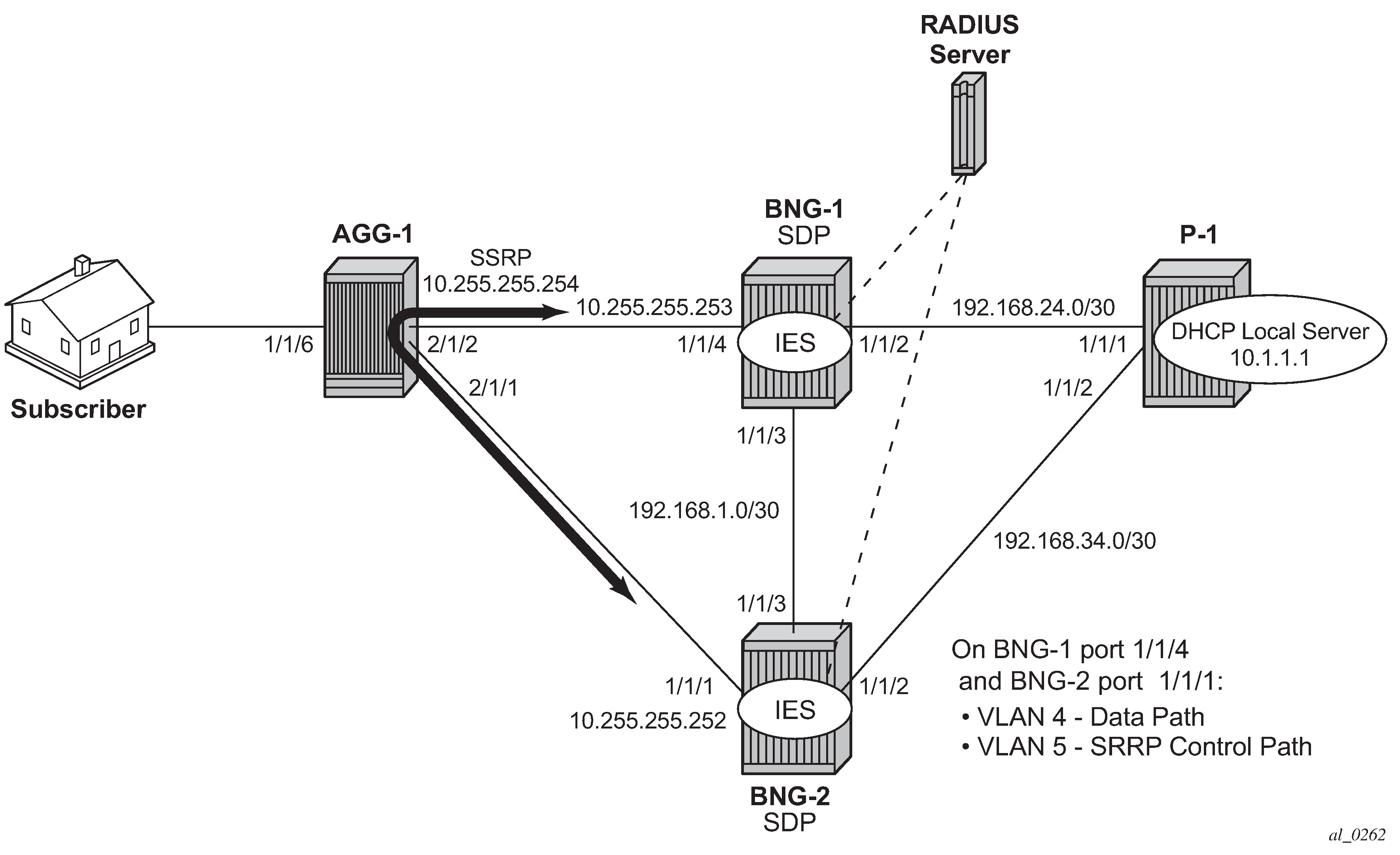
Example Topology shows the addressing scheme used in the setup. The example uses numbered SRRP subscriber interfaces with static SAPs serving both IPoE and PPPoE subscribers. The configuration of the RADIUS server is out of the scope of this example.
The baseline configuration for BNG-1 follows, excluding the IGMP configuration. In this example, the subscriber-interface is configured in an IES, although it is possible to configure the subscriber-interface in a VPRN. OSPF and PIM are provisioned to provide routing and multicast capabilities. The SRRP configuration with priority 200 ensures BNG-1 is the master when both BNGs are active because the SRRP priority for BNG-2 is lower.
# BNG-1
configure
    service
        ies 1 customer 1 create
            redundant-interface "mclink-BNG-1-BNG-2" create
                address 192.168.11.0/31
                ip-mtu 1500
                spoke-sdp 23:1 create
                    no shutdown
                exit
            exit
            subscriber-interface "sub-int-1" create
                address 10.255.255.252/8 gw-ip-address 10.255.255.254 track-srrp 1
                group-interface "grp-int-1" create
                    srrp-enabled-routing
                    dhcp
                        option
                            action replace
                            circuit-id
                            no remote-id
                        exit
                        server 192.168.0.1
                        lease-populate 10
                        client-applications dhcp ppp
                        gi-address 10.255.255.252
                        no shutdown
                    exit
                    authentication-policy "auth-1"
                    redundant-interface "mclink-BNG-1-BNG-2"
                    sap 1/1/4:4 create
                        sub-sla-mgmt
                            def-sub-id use-sap-id
                            def-sub-profile "sub-profile-1"
                            def-sla-profile "sla-profile-1"
                            sub-ident-policy "sub-ident-1"
                            multi-sub-sap 10
                            no shutdown
                        exit
                    exit
                    sap 1/1/4:5 create
                    exit
                    srrp 1 create
                        message-path 1/1/4:5
                        priority 200
                        no preempt
                        no shutdown
                    exit
                    pppoe
                        no shutdown
                    exit
                exit
            exit
            no shutdown
        exit
    exit
exit
configure
    router
        ospf
            area 0.0.0.0
                interface "system"
                    no shutdown
                exit
                interface "int-BNG-1-BNG-2"
                    interface-type point-to-point
                    metric 10000
                    no shutdown
                exit
                interface "int-BNG-1-P-1"
                    interface-type point-to-point
                    no shutdown
                exit
                interface "sub-int-1"
                    no shutdown
                exit
            exit
            no shutdown
        exit
        pim
            interface "int-BNG-1-P-1"
            exit
            no shutdown
        exit
    exit
exit
The baseline configuration for BNG-2 follows, excluding the IGMP configuration. The SRRP priority for BNG-2 is lower than the SRRP priority for BNG-1, thus BNG-2 will be in standby mode.
# BNG-2
configure
    service
        ies 1 customer 1 create
            no shutdown
            redundant-interface "mclink-BNG-2-BNG-1" create
                address 192.168.11.1/31
                ip-mtu 1500
                spoke-sdp 32:1 create
                    no shutdown
                exit
            exit
            subscriber-interface "sub-int-1" create
                address 10.255.255.253/8 gw-ip-address 10.255.255.254 track-srrp 1
                group-interface "grp-int-1" create
                    srrp-enabled-routing
                    dhcp
                        option
                            action replace
                            circuit-id
                            no remote-id
                        exit
                        server 192.168.0.1
                        lease-populate 10
                        client-applications dhcp ppp
                        gi-address 10.255.255.253
                        no shutdown
                    exit
                    authentication-policy "auth-1"
                    redundant-interface "mclink-BNG-2-BNG-1"
                    sap 1/1/1:4 create
                        sub-sla-mgmt
                            def-sub-id use-sap-id
                            def-sub-profile "sub-profile-1"
                            def-sla-profile "sla-profile-1"
                            sub-ident-policy "sub-ident-1"
                            multi-sub-sap 10
                            no shutdown
                        exit
                    exit
                    sap 1/1/1:5 create
                    exit
                    srrp 1 create
                        message-path 1/1/1:5
                        priority 150
                        no preempt
                        no shutdown
                    exit
                    pppoe
                        no shutdown
                    exit
                exit
            exit
            no shutdown
        exit
    exit
exit
configure
    router
        ospf
            area 0.0.0.0
                interface "system"
                    no shutdown
                exit
                interface "int-BNG-2-BNG-1"
                    interface-type point-to-point
                    metric 10000
                    no shutdown
                exit
                interface "int-BNG-2-P-1"
                    interface-type point-to-point
                    no shutdown
                exit
                interface "sub-int-1"
                    no shutdown
                exit
            exit
            no shutdown
        exit
        pim
            interface "int-BNG-2-P-1"
            exit
            no shutdown
        exit
    exit
exit
The baseline configuration for the aggregation switch AGG-1 follows. Two VPLS services are configured. VPLS 5 is responsible for passing SRRP control traffic over VLAN 5. VPLS 4 is responsible for passing all subscriber data traffic over VLAN 4.
# AGG-1
configure
    service
        vpls 4 customer 1 create
            description "for user traffic"
            stp
                shutdown
            exit
            sap 1/1/6:4 create
                no shutdown
            exit
            sap 2/1/1:4 create
                no shutdown
            exit
            sap 2/1/2:4 create
                no shutdown
            exit
            no shutdown
        exit
        vpls 5 customer 1 create
            description "for SRRP/redundancy"
            stp
                shutdown
            exit
            sap 2/1/1:5 create
                no shutdown
            exit
            sap 2/1/2:5 create
                no shutdown
            exit
            no shutdown
        exit
    exit
exit
The baseline configuration on the P router is as follows. The P router has a local DHCP server configured and performs the DHCP address assignment. The P router also is attached to the multicast source and uses PIM to deliver multicast streams.
# P-1
configure
    router Base
        dhcp
            local-dhcp-server "dhcp-local-server" create
                use-gi-address scope pool
                pool "pool-1" create
                    subnet 10.0.0.0/8 create
                        options
                            subnet-mask 255.0.0.0
                            default-router 10.255.255.254
                        exit
                        address-range 10.0.0.10 10.0.0.254
                    exit
                exit
                no shutdown
            exit
        exit
        interface "int-DHCP-lb1"
            address 192.168.0.1/32
            loopback
            local-dhcp-server "dhcp-local-server"
            no shutdown
        exit
        interface "int-P-1-BNG-1"
            address 192.168.24.2/30
            port 1/1/1:4094
            no shutdown
        exit
        interface "int-P-1-BNG-2"
            address 192.168.34.2/30
            port 1/1/2:4094
            no shutdown
        exit
        interface "int-P-1-mcast-source"
            address 192.168.4.1/30
            port 1/1/5:4092
            no shutdown
        exit
        interface "system"
            address 192.0.2.4/32
            no shutdown
        exit
        ospf 0
            traffic-engineering
            area 0.0.0.0
                interface "system"
                    no shutdown
                exit
                interface "int-DHCP-lb1"
                    no shutdown
                exit
                interface "int-P-1-BNG-1"
                    interface-type point-to-point
                    no shutdown
                exit
                interface "int-P-1-BNG-2"
                    interface-type point-to-point
                    no shutdown
                exit
                interface "int-P-1-mcast-source"
                    passive
                    no shutdown
                exit
            exit
            no shutdown
        exit
        pim
            interface "int-P-1-BNG-1"
            exit
            interface "int-P-1-BNG-2"
            exit
            interface "int-P-1-mcast-source"
            exit
            ---snip---
            no shutdown
        exit
    exit
exit
Enable IGMP on Group Interfaces
The configuration below adds the group interface to IGMP. If the subscriber-interface is configured in a VPRN, each VPRN will have its individual IGMP instance. Add the group-interface to the IGMP instance.
# on BNG-1 and BNG-2
configure
    router
        igmp
            group-interface "grp-int-1"
                no shutdown
            exit
            no shutdown
        exit
    exit
exit
Placing the group-interface into IGMP is the first step required to deliver multicast streams. The options available in this IGMP context can be classified into two categories:
Bandwidth and multicast group management
Interoperability
 [no] disable-router* - Enable/disable the IGMP router alert check option
 [no] import          - Import a policy to filter IGMP packets
 [no] max-groups      - Configure the maximum number of groups for this group-interface
 [no] max-grp-sources - Configure the maximum number of group sources for this
                        group-interface
 [no] max-sources     - Configure the maximum number of sources for this group-interface
      mcac            + Configure multicast CAC policy and constraints for this interface
 [no] query-interval  - Configure the frequency at which Host-Query packets are
                        transmitted
 [no] query-last-mem* - Configure the frequency at which Group-Specific-Query packets
                        are transmitted
 [no] query-response* - Configure the time to wait to receive a response to the
                        Host-Query message from the host
 [no] query-src-ip    - Configure the IP source address used in IGMP queries for this
                        group interface
 [no] shutdown        - Administratively enable/disable the interface
 [no] sub-hosts-only  - Enable/disable the IGMP traffic from known hosts only
 [no] subnet-check    - Enable/disable local subnet checking for IGMP
 [no] version         - Configure the version of IGMP
The bandwidth and multicast group management options are:
Import — Used for white-listing or black-listing multicast groups in the IGMP control plane. More configuration detail is offered in a later section.
Max-groups — Controls the maximum number of groups (channels) allowed on the group interface.
Max-sources — Controls the maximum number of sources of the multicast streams on a group interface.
Max-grp-sources — Specifies the maximum number of multicast group and source pairs for a group-interface.
MCAC — Multicast Connection Admission Control (MCAC) is a bandwidth management feature to control the amount of multicast streams a group interface is allowed to receive. It can also be applied at subscriber level to offer a hierarchical control. Multicast bandwidth can be controlled on a per subscriber basis.
query-interval — defines the frequency at which general host-query messages are sent out by the querier.
query-last-member-interval — defines the frequency at which the querier sends group-specific queries including messages sent in response to leave-group messages.
query-response-interval — defines how long the querier waits to receive a response to a host-query message from a host.
query-src-ip — defines the query source IP address for the group interface.
The interoperability options available are:
Router alert — enable or disable router alert processing.
Sub-hosts-only — Only subscriber originated IGMP messages are accepted and anything else is ignored. Sometimes, IGMP message might not arrive directly from the subscriber. For example, an aggregation switch or DSLAM residing between the CPE and the BNG might perform IGMP proxy. The switch/DSLAM will insert its own source IP-address in place of the subscriber.
It should be noted that, when an IGMP proxy is used, the identity of the subscriber is lost (because the original source IP of the IGMP message is replaced).
Subnet-check — IGMP messages will be checked against the group interface subnet. All IGMP messages with a source address that is not in the local subnet are dropped.
Version — The RFCs define three versions of IGMP, all of them are supported by SR OS.
It must be noted that when subscribers are sending IGMPv1 or v2 in a bridged LAN, suppression of IGMP messages can occur. If an IGMP host detects the presence of another host reporting for the same multicast group, it will suppress its own IGMP report message and silently receive the multicast stream. When IGMP messages are suppressed, the BNG might not be able to account for the real multicast bandwidth consumption of each subscriber. IGMPv3, on the other hand, forces all hosts to send IGMP reports. This guarantees that the BNG identifies each subscriber’s IGMP request.
ESM IGMP Policy
In addition to enabling IGMP on the group interface, the subscriber must be allowed to receive multicast streams through an IGMP policy. For this purpose, the IGMP-policy is associated with the subscriber’s subscriber-profile. Therefore during authentication, either RADIUS, the local user database (LUDB), or the default-sub-profile should return a sub-profile with an IGMP policy. The provisioning requires two steps:
First create the IGMP policy, as follows:
configure
    subscriber-mgmt
        igmp-policy "igmp-policy-1" create
        exit
    exit
exit
Then add the IGMP policy to a subscriber-profile, as follows:
configure
    subscriber-mgmt
        sub-profile "sub-profile-1" create
            igmp-policy "igmp-policy-1"
        exit
    exit
exit
The above configuration is the minimum requirement for a subscriber to receive multicast streams. The different options inside an IGMP policy are:
 [no] description     - Description for the policy
 [no] disable-router* - Enable/disable the router alert check option
 [no] egress-rate-mo* - Configure the egress rate modification
 [no] fast-leave      - Enable/disable fast-leave processing
 [no] import          - Specify the import policy to filter packets
 [no] max-num-groups  - Configure the max number of multicast groups
 [no] max-num-grp-so* - Configure the max number of multicast group sources
 [no] max-num-sources - Configure the max number of multicast sources
 [no] mcast-reporting + Configure the mcast reporting
 [no] per-host-repli* - Enable/disable per-host-replication processing
 [no] query-interval  - Configure the frequency at which Host-Query packets are
                        transmitted
 [no] query-last-mem* - Configure the frequency at which Group-Specific-Query packets
                        are transmitted
 [no] query-response* - Configure the time to wait to receive a response to the
                        Host-Query message from the host
 [no] redirection-po* - Specify the redirection policy
      static          + Add/remove static group membership
 [no] version         - Configure the version
Again, two groups of options are available: the bandwidth and multicast group management options, and the interoperability options.
Bandwidth and multicast group management options:
Import — Used for white-listing and black-listing multicast groups. This allows the import policy to be defined per subscriber.
Max-num-group — Limits the maximum multicast groups for the group interface. This limits the groups per subscriber.
Max-num-sources — Limits the maximum multicast sources for the group interface. This limits the sources per subscriber.
Max-num-grp-sources — Limits the maximum multicast group and source pairs for the group interface.
Egress-rate-modify — This feature adjusts the subscriber queue bandwidth according to multicast consumption. It is used in conjunction with MCAC. An MCAC policy defines the bandwidth consumption per multicast group. As a subscriber joins a multicast group, the bandwidth of the multicast channel is subtracted from the subscriber queue bandwidth. The remaining bandwidth is what the subscriber can use for all other services.
query-interval — defines the frequency at which general host-query messages are sent out by the querier.
query-last-member-interval — defines the frequency at which the querier sends group-specific queries including messages sent in response to leave-group messages.
query-response-interval — defines how long the querier waits to receive a response to a host-query message from a host.
Interoperability options:
Fast-leave — Enables the router to withdraw the multicast group quickly when receiving an IGMP leave message without any last query. This should be used in a subscriber per SAP (dot1q or qinq) model.
Static — This allows the provisioning of static multicast groups that the subscriber will receive regardless of any IGMP report. The static multicast group can be Source Specific Multicast (SSM) based.
Per-host-replication — SR OS has the capability to replicate a multicast source per subscriber. For example, if 10 subscribers are requesting the same multicast group, then 10 multicast streams are replicated and delivered individually to each subscriber. PPPoE requires service delivery to be point to point. To achieve this, the Ethernet header destination address for the multicast stream is the subscriber’s source MAC. The IP layer destination is the same as the multicast group that the subscriber requested. For IPoE, without per-host replication, the standard multicast MAC representing the multicast group is used as the destination MAC address when delivering the multicast streams to the subscribers. When per-host replication is used for IPoE subscribers, the destination MAC address will be the host’s own MAC address and the IP destination will be the same as the multicast group that the subscriber is interested in. The multicast stream is then delivered to the subscriber via MAC learning as a unicast stream.
When per-host-replication is enabled, all multicast streams will be using the subscriber queues. It is no longer necessary to use egress-rate-modify as mentioned before.
Redirection-policy — Another popular model for multicast deployment is to redirect all multicast streams to another interface instead of sending the content directly to the subscriber. All subscribers use a common VLAN to receive the multicast streams.
ESM IGMP IPoE Walkthrough
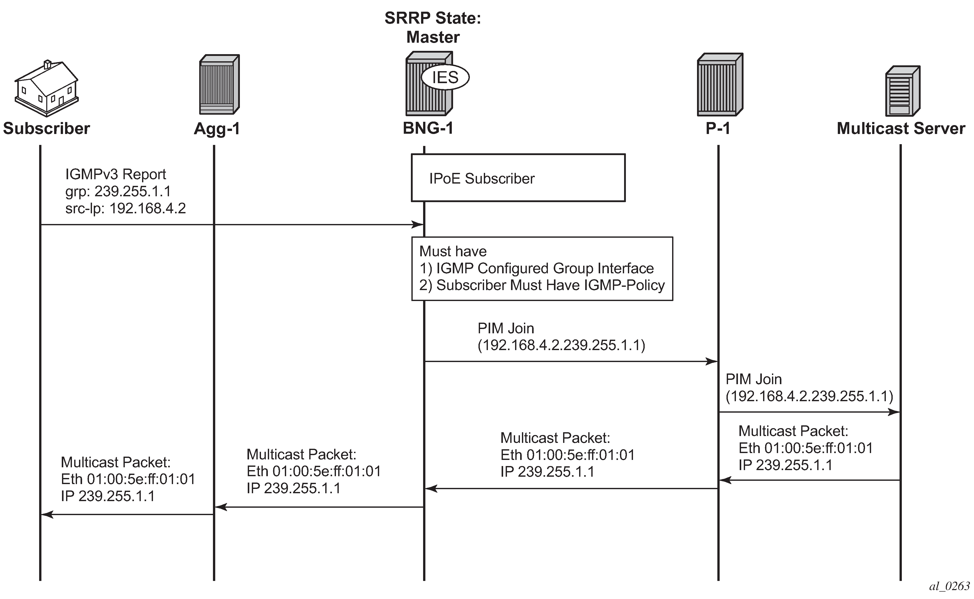
With the baseline configuration applied, the BNG is ready to process IGMP messages and deliver multicast. IPoE Subscriber Multicast Flow shows a flow for IPoE subscribers requesting and receiving multicast traffic. The key items are highlighted in dotted box:
The ESM group-interface must have IGMP enabled
The subscriber must be associated with an IGMP-policy via sub-profile.
The subscriber sends an IGMPv3 report using (192.168.4.2, 239.255.1.1).
To verify that the group interface is ready for multicast, use the following show command. Remember that the IES service id is 1 and the group-interface name is grp-int-1.
*A:BNG-1# show router igmp group-interface

===============================================================================
IGMP Group-Interfaces
===============================================================================
FwdSvc Group-Interface                  Adm/Opr-State        Import-Policy
       SAP                              Adm/Opr-Version      Num-Groups
-------------------------------------------------------------------------------
1      grp-int-1                        Up/Up                none
       1/1/4:4                          3/3                  0
       1/1/4:5                          3/3                  0
-------------------------------------------------------------------------------
Group-Interfaces = 1, SAPs = 2
===============================================================================
*A:BNG-1#
Ensure the subscriber is associated with an IGMP-policy. Since the IGMP-policy is associated with a subscriber-profile, verifying the IGMP-policy is done through the subscriber profile, as follows:
*A:BNG-1# show subscriber-mgmt sub-profile "sub-profile-1"

===============================================================================
Subscriber Profile sub-profile-1
===============================================================================
Description      : (Not Specified)
I. Sched. Policy : N/A
E. Sched. Policy : N/A                              E. Agg Rate Limit: Max
I. Policer Ctrl. : N/A
E. Policer Ctrl. : N/A
I. vport-hashing : Disabled
I. sec-sh-hashing: Disabled
Q Frame-Based Ac*: Disabled
Acct. Policy     : N/A                              Collect Stats    : Disabled
ANCP Pol.        : N/A
Accu-stats-pol   : (Not Specified)
HostTrk Pol.     : N/A
IGMP Policy      : igmp-policy-1
MLD Policy       : N/A
PIM Policy       : N/A
Sub. MCAC Policy : N/A
NAT Policy       : N/A
Firewall Policy  : N/A
UPnP Policy      : N/A
NAT Prefix List  : N/A
Def. Encap Offset: none                             Encap Offset Mode: none
Avg Frame Size   : N/A
Vol stats type   : full
Preference       : 5
LAG hash class   : 1
LAG hash weight  : 1
-------------------------------------------------------------------------------
Radius Accounting
-------------------------------------------------------------------------------
Policy           : N/A
Session Opti.Stop: False
-------------------------------------------------------------------------------
HSMDA-2
-------------------------------------------------------------------------------
I. Qos Policy    : 1                                E. Qos Policy    : 1
                                                    E. Agg Rate Limit: Max
E. WRR Policy    : N/A                              Pkt Byte Offset  : add 0*
-------------------------------------------------------------------------------
Last Mgmt Change : 06/21/2017 11:58:50
===============================================================================
* indicates that the corresponding row element may have been truncated.

---snip---

*A:BNG-1#
After the verification, the BNGs are ready to deliver multicast streams.
First, initiate an IGMP report from a subscriber requesting a multicast channel. In this example, IGMPv3 SSM is used. IPoE by default replicates per-SAP. If the IGMP message was successfully received and processed, an (S,G) binding will be associated with the subscriber SAP.
In this case, the IGMPv3 SSM message requests (192.168.4.2, 239.255.1.1). The subscriber host is assigned an IP address of 10.0.0.11. To verify the IGMP message was successfully processed, check that the (S,G) is learned on the IGMP instance. The following example shows a successful IGMP message processed by the BNG, the (S,G) is registered against the subscriber SAP and the host.
*A:BNG-1# show router igmp group
===============================================================================
IGMP Interface Groups
===============================================================================
No Matching Entries
===============================================================================
IGMP Host Groups
===============================================================================
(192.168.4.2,239.255.1.1)
    Fwd List  : 10.0.0.11                                 UpTime: 0d 00:05:27
-------------------------------------------------------------------------------
Entries : 1
===============================================================================
IGMP SAP Groups
===============================================================================
(192.168.4.2,239.255.1.1)
    Fwd List  : 1/1/4:4                                   UpTime: 0d 00:05:27
-------------------------------------------------------------------------------
Entries : 1
===============================================================================
*A:BNG-1#
For more IGMP details on the group interface, including maximum multicast groups and bandwidth management, use the following command:
*A:BNG-1# show router igmp group-interface detail

===============================================================================
IGMP Group-Interfaces
===============================================================================
FwdSvc/Grp-Intf    : 1/grp-int-1
Admin-Status       : Up                 Oper-Status        : Up
Import-Policy      : none               Subnet-Check       : Enabled
Router-Alert-Check : Enabled            Sub-Hosts-Only     : Enabled
MCAC Policy Name   :                    MCAC Const Adm St  : Enable
MCAC Max Unconst BW: no limit           MCAC Max Mand BW   : no limit
MCAC In use Mand BW: 0                  MCAC Avail Mand BW : unlimited
MCAC In use Opnl BW: 0                  MCAC Avail Opnl BW : unlimited
Qry Interval       : None               Qry Last Mbr Inter*: None
Qry Resp Interval  : None
MCAC If-Policy Name:
-------------------------------------------------------------------------------
 SAP               : 1/1/4:4
 Admin/Oper version: 3/3                Num Groups         : 1
 Max Groups Allowed: No Limit           Max Groups Till Now: 1
 Max Sources Allow*: No Limit
 Max Grp Srcs Allo*: No Limit
 Qry Interval      : 125                Qry Last Memb Inte*: 1
 Qry Resp Interval : 10
-------------------------------------------------------------------------------
  Group-Address    : 239.255.1.1        Up Time            : 0d 00:05:54
  Expires          : N/A                Mode               : include
  V1 Host Timer    : Not running        Type               : dynamic
  V2 Host Timer    : Not running        Compat Mode        : IGMP Version 3
   ------------------------------------------------------------------
   GrpSrc-Address    Expires            Type                 Fwd/Blk
   ------------------------------------------------------------------
   192.168.4.2       0d 00:04:18        dynamic              Fwd
-------------------------------------------------------------------------------
 SAP               : 1/1/4:5
 Admin/Oper version: 3/3                Num Groups         : 0
 Max Groups Allowed: No Limit           Max Groups Till Now: 0
 Max Sources Allow*: No Limit
 Max Grp Srcs Allo*: No Limit
 Qry Interval      : 125                Qry Last Memb Inte*: 1
 Qry Resp Interval : 10
-------------------------------------------------------------------------------
Group-Interfaces = 1, SAPs = 2
===============================================================================
* indicates that the corresponding row element may have been truncated.
*A:BNG-1#
If the subscriber fails to receive multicast traffic, check if the subscriber has an associated IGMP policy with the following command. If the subscriber entry is missing, make sure the subscriber has a sub-profile that is tied to an IGMP-policy.
*A:BNG-1# show service active-subscribers igmp detail

===============================================================================
Active Subscribers Detail
===============================================================================
Subscriber                       IGMP-Policy
  HostAddr                       GrpItf                           NumGroups
    GrpAddr                      Type            Up-Time          Mode
      SrcAddr                    Type                             Blk/Fwd
-------------------------------------------------------------------------------
subscr-1                         igmp-policy-1
  10.0.0.11                      grp-int-1                        1
    239.255.1.1                  Dynamic         0d 00:08:50      Include
      192.168.4.2                Dynamic                          Fwd
-------------------------------------------------------------------------------
Number of Subscribers : 1
===============================================================================
*A:BNG-1#
Another possibility for failing to receive multicast traffic could be due to the control mechanisms inside the IGMP-policy such as: bandwidth control, multicast groups restrictions, and interoperability options. Use the following command to view the IGMP policy configured control parameters.
*A:BNG-1# show subscriber-mgmt igmp-policy "igmp-policy-1"

===============================================================================
IGMP Policy igmp-policy-1
===============================================================================
Import Policy                         :
Admin Version                         : 3
Num Subscribers                       : 1
Host Max Group                        : No Limit
Host Max Sources                      : No Limit
Host Max Group Sources                : No Limit
Query Interval                        : None
Query Last Member Interval            : None
Query Response Interval               : None
Router Alert Check                    : Enabled
Fast Leave                            : yes
Redirection Policy                    :
Per Host Replication                  : no
Egress Rate Modify                    : no
Mcast Reporting Destination Name      :
Mcast Reporting Admin State           : Disabled
===============================================================================
*A:BNG-1#
The command to view the (S,G)s that all subscribers are requesting is as follows. Since the system has only one subscriber, this example only shows one host.
*A:BNG-1# show router igmp hosts detail

===============================================================================
IGMP Host 10.0.0.11
===============================================================================
Oper Status      : Up         MacAddress     : 00:10:94:00:00:13
Oper version     : 3          Subscriber     : subscr-1
Num Groups       : 1          GrpItf         : grp-int-1
Max Grps Till Now: 1          IGMP-Policy    : igmp-policy-1
PPPoE SessionId  : N/A        Next query time: 0d 00:01:29
FwdSvcId         : 1          Max Srcs Allow*: No Limit
Max Grps Allowed : No Limit   Max Grp Srcs A*: No Limit
Qry Interval     : 125        Qry Last Mbr I*: 1
Qry Resp Interval: 10         Router Alert C*: Enabled

-------------------------------------------------------------------------------
IGMP Group
-------------------------------------------------------------------------------
Group Address    : 239.255.1.1    Up Time    : 0d 00:10:30
Expires          : Not running    Mode       : Include
V1 Host Timer    : Not running    Type       : Dynamic
V2 Host Timer    : Not running    Compat Mode: IGMP Version 3
Redir.SvcId      : N/A            Redir.Intf : N/A
-----------------------------------------------------------
Source Address     Expires        Type         Fwd/Blk
-----------------------------------------------------------
192.168.4.2        0d 00:03:46    Dynamic      Fwd
-------------------------------------------------------------------------------
Hosts : 1
===============================================================================
* indicates that the corresponding row element may have been truncated.
*A:BNG-1#
To check for an individual subscriber and its requested (S,G)s, the following command can be used.
*A:BNG-1# show service active-subscribers igmp subscriber "subscr-1" detail

===============================================================================
Active Subscribers Detail
===============================================================================
Subscriber                       IGMP-Policy
  HostAddr                       GrpItf                           NumGroups
    GrpAddr                      Type            Up-Time          Mode
      SrcAddr                    Type                             Blk/Fwd
-------------------------------------------------------------------------------
subscr-1                         igmp-policy-1
  10.0.0.11                      grp-int-1                        1
    239.255.1.1                  Dynamic         0d 00:13:31      Include
      192.168.4.2                Dynamic                          Fwd
-------------------------------------------------------------------------------
Number of Subscribers : 1
===============================================================================
*A:BNG-1#
ESM IGMP PPPoE Walkthrough
IGMP message processing and delivery of multicast streams to PPPoE subscribers is considered next. PPPoE Multicast Flow shows the message flow for multicast stream delivery to PPPoE subscribers.
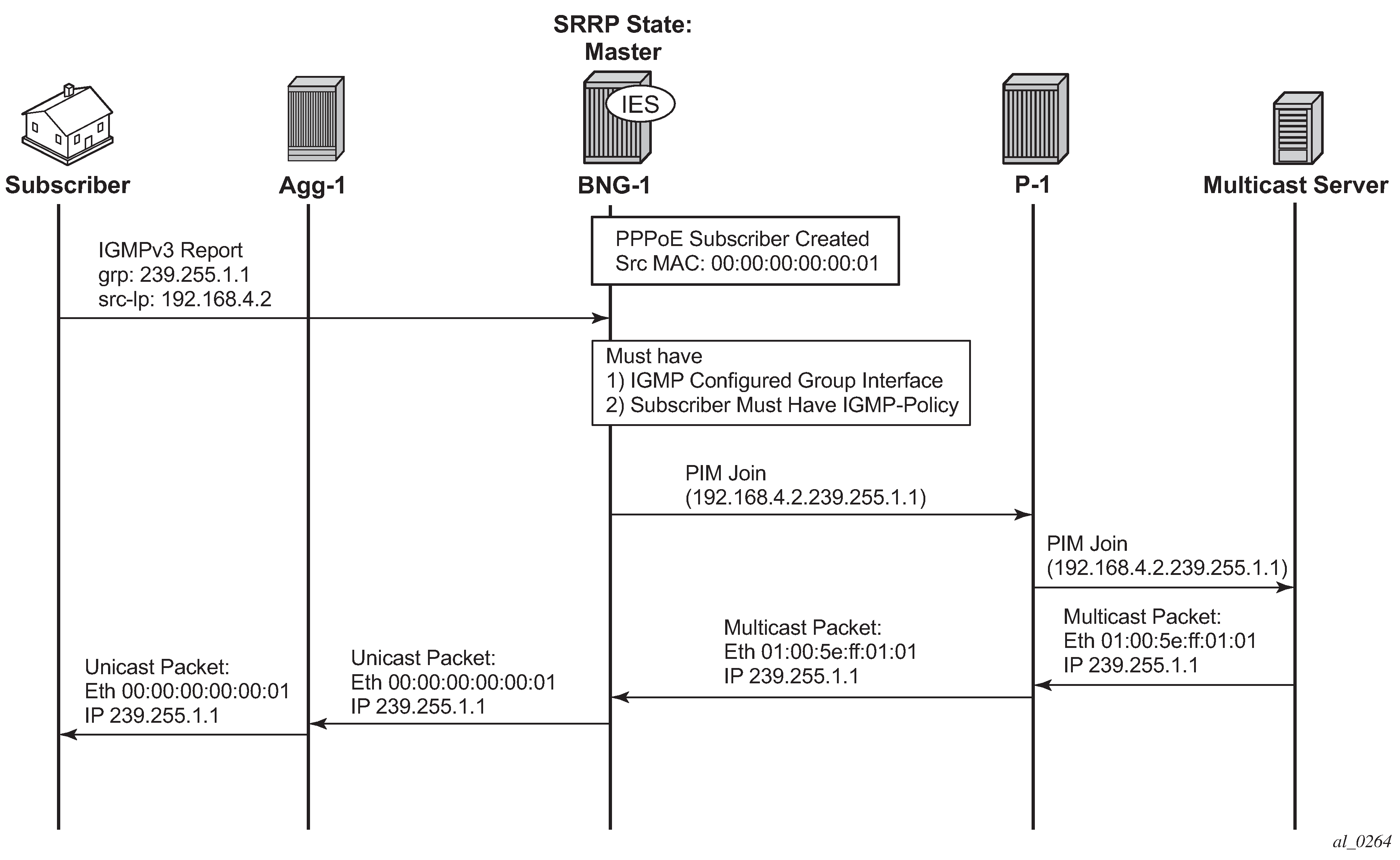
As stated earlier, the important configuration aspects are highlighted in the dotted box. The main difference between IPoE subscribers and PPPoE subscribers is the encapsulation on the last stretch of the multicast data path. PPPoE subscribers receive multicast streams via Ethernet unicast while IPoE subscribers receive multicast streams via Ethernet multicast. PPPoE natively does not have a multicast mechanism and requires all data traffic to be unicasted. Even if the subscribers are on the same SAP, multicast streams are replicated per subscriber. To achieve this, the IP header indicates a multicast address while the Ethernet header destination MAC address is changed to the subscriber’s MAC address.
Verify the group interface. It is very similar to the output for the IPoE group interface.
*A:BNG-1# show router igmp group-interface detail

===============================================================================
IGMP Group-Interfaces
===============================================================================
FwdSvc/Grp-Intf    : 1/grp-int-1
Admin-Status       : Up                 Oper-Status        : Up
Import-Policy      : none               Subnet-Check       : Enabled
Router-Alert-Check : Enabled            Sub-Hosts-Only     : Enabled
MCAC Policy Name   :                    MCAC Const Adm St  : Enable
MCAC Max Unconst BW: no limit           MCAC Max Mand BW   : no limit
MCAC In use Mand BW: 0                  MCAC Avail Mand BW : unlimited
MCAC In use Opnl BW: 0                  MCAC Avail Opnl BW : unlimited
Qry Interval       : None               Qry Last Mbr Inter*: None
Qry Resp Interval  : None
MCAC If-Policy Name:
Bonding connection : N/A
-------------------------------------------------------------------------------
 SAP               : 1/1/4:4
 Admin/Oper version: 3/3                Num Groups         : 0
 Max Groups Allowed: No Limit           Max Groups Till Now: 1
 Max Sources Allow*: No Limit
 Max Grp Srcs Allo*: No Limit
 Qry Interval      : 125                Qry Last Memb Inte*: 1
 Qry Resp Interval : 10
-------------------------------------------------------------------------------
 SAP               : 1/1/4:5
 Admin/Oper version: 3/3                Num Groups         : 0
 Max Groups Allowed: No Limit           Max Groups Till Now: 0
 Max Sources Allow*: No Limit
 Max Grp Srcs Allo*: No Limit
 Qry Interval      : 125                Qry Last Memb Inte*: 1
 Qry Resp Interval : 10
-------------------------------------------------------------------------------
Group-Interfaces = 1, SAPs = 2
===============================================================================
* indicates that the corresponding row element may have been truncated.
*A:BNG-1#
Next an IGMPv3 message is sent toward the BNG. The (S,G) is (192.168.4.2, 239.255.1.1). The PPPoE subscriber is assigned an IP address of 10.0.0.15.
The following output shows the key difference between a PPPoE subscriber and an IPoE subscriber. A PPPoE multicast stream is replicated per host and not per SAP. This output shows this clearly because the multicast group is associated with the host and not with the SAP.
*A:BNG-1# show router igmp group
===============================================================================
IGMP Interface Groups
===============================================================================
No Matching Entries
===============================================================================
IGMP Host Groups
===============================================================================
(192.168.4.2,239.255.1.1)
    Fwd List  : 10.0.0.15                                 UpTime: 0d 00:03:39
-------------------------------------------------------------------------------
Entries : 1
===============================================================================
IGMP SAP Groups
===============================================================================
No Matching Entries
===============================================================================
*A:BNG-1#
The next command shows all of the subscribers and all the (S,G)s joined. In this case there is only one PPPoE subscriber.
*A:BNG-1# show router igmp hosts detail

===============================================================================
IGMP Host 10.0.0.15
===============================================================================
Oper Status      : Up         MacAddress     : 00:10:94:00:00:14
Oper version     : 3          Subscriber     : pppoe-sub-1
Num Groups       : 1          GrpItf         : grp-int-1
Max Grps Till Now: 1          IGMP-Policy    : igmp-policy-1
PPPoE SessionId  : 1          Next query time: 0d 00:01:02
FwdSvcId         : 1          Max Srcs Allow*: No Limit
Max Grps Allowed : No Limit   Max Grp Srcs A*: No Limit
Qry Interval     : 125        Qry Last Mbr I*: 1
Qry Resp Interval: 10         Router Alert C*: Enabled

-------------------------------------------------------------------------------
IGMP Group
-------------------------------------------------------------------------------
Group Address    : 239.255.1.1    Up Time    : 0d 00:05:03
Expires          : Not running    Mode       : Include
V1 Host Timer    : Not running    Type       : Dynamic
V2 Host Timer    : Not running    Compat Mode: IGMP Version 3
Redir.SvcId      : N/A            Redir.Intf : N/A
-----------------------------------------------------------
Source Address     Expires        Type         Fwd/Blk
-----------------------------------------------------------
192.168.4.2        0d 00:03:22    Dynamic      Fwd
-------------------------------------------------------------------------------
Hosts : 1
===============================================================================
* indicates that the corresponding row element may have been truncated.
*A:BNG-1#
To view each individual subscriber and their respective (S,G)s, use the following command.
*A:BNG-1# show service active-subscribers igmp subscriber "pppoe-sub-1" detail

===============================================================================
Active Subscribers Detail
===============================================================================
Subscriber                       IGMP-Policy
  HostAddr                       GrpItf                           NumGroups
    GrpAddr                      Type            Up-Time          Mode
      SrcAddr                    Type                             Blk/Fwd
-------------------------------------------------------------------------------
pppoe-sub-1                      igmp-policy-1
  10.0.0.15                      grp-int-1                        1
    239.255.1.1                  Dynamic         0d 00:07:31      Include
      192.168.4.2                Dynamic                          Fwd
-------------------------------------------------------------------------------
Number of Subscribers : 1
===============================================================================
*A:BNG-1#
ESM IGMP MCS
The BNGs are configured with SRRP for both IPoE and PPPoE subscribers. This provides stateful redundancy when the master BNG fails. The master BNG will be the only one processing and answering IGMP messages. The standby BNG does not perform any IGMP processing and receives updates through MCS for all subscribers in real time. In the event of a failure, the standby will become active and starts processing all IGMP messages. The standby will also immediately trigger PIM joins for all of the subscribers’s (S,G)s. This is all possible because the standby is always synchronized with the master BNG prior to the failover. Restoration of all multicast channels should happen quickly after the failover and depends on both the PIM configuration and the underlying routing infrastructure.
The key parameters for MCS for ESM multicast are: syncing of subscribers (ipoe, pppoe), SRRP and IGMP. The redundancy configuration for BNG-1 is as follows. The configuration for BNG-2 is similar.
configure
    redundancy
        multi-chassis
            peer 192.0.2.3 create
                sync
                    igmp
                    srrp
                    sub-mgmt ipoe pppoe
                    port 1/1/4 create
                        range 4-4 sync-tag "sub"
                        range 5-5 sync-tag "srrp"
                    exit
                    no shutdown
                exit
                no shutdown
            exit
        exit
    exit
exit
The following command displays the number of entries being synced across the BNGs.
*A:BNG-1# show redundancy multi-chassis sync peer 192.0.2.3 detail

===============================================================================
Multi-chassis Peer Table
===============================================================================
Peer
-------------------------------------------------------------------------------
Peer IP Address         : 192.0.2.3
Description             : (Not Specified)
Authentication          : Disabled
Source IP Address       : 192.0.2.2
Admin State             : Enabled
Warm standby            : No
Remote warm standby     : No
-------------------------------------------------------------------------------
Sync-status
-------------------------------------------------------------------------------
Client Applications     : IGMP SUBMGMT-IPOE SUBMGMT-PPPOE SRRP
Sync Admin State        : Up
Sync Oper State         : Up
Sync Oper Flags         :
DB Sync State           : inSync
Num Entries             : 29
Lcl Deleted Entries     : 0
Alarm Entries           : 0
OMCR Standby Entries    : 0
OMCR Alarm Entries      : 0
Rem Num Entries         : 29
Rem Lcl Deleted Entries : 0
Rem Alarm Entries       : 0
Rem OMCR Standby Entries: 0
Rem OMCR Alarm Entries  : 0

===============================================================================
MCS Application Stats
===============================================================================
Application             : igmp
Num Entries             : 2
Lcl Deleted Entries     : 0
Alarm Entries           : 0
OMCR Standby Entries    : 0
OMCR Alarm Entries      : 0
-------------------------------------------------------------------------------
Rem Num Entries         : 2
Rem Lcl Deleted Entries : 0
Rem Alarm Entries       : 0
Rem OMCR Standby Entries: 0
Rem OMCR Alarm Entries  : 0
-------------------------------------------------------------------------------
Application             : igmpSnooping
Num Entries             : 0
Lcl Deleted Entries     : 0
Alarm Entries           : 0
OMCR Standby Entries    : 0
OMCR Alarm Entries      : 0
-------------------------------------------------------------------------------
Rem Num Entries         : 0
Rem Lcl Deleted Entries : 0
Rem Alarm Entries       : 0
Rem OMCR Standby Entries: 0
Rem OMCR Alarm Entries  : 0
-------------------------------------------------------------------------------
Application             : subMgmtIpoe
Num Entries             : 1
Lcl Deleted Entries     : 0
Alarm Entries           : 0
OMCR Standby Entries    : 0
OMCR Alarm Entries      : 0
-------------------------------------------------------------------------------
Rem Num Entries         : 1
Rem Lcl Deleted Entries : 0
Rem Alarm Entries       : 0
Rem OMCR Standby Entries: 0
Rem OMCR Alarm Entries  : 0
-------------------------------------------------------------------------------
Application             : srrp
Num Entries             : 26
Lcl Deleted Entries     : 0
Alarm Entries           : 0
OMCR Standby Entries    : 0
OMCR Alarm Entries      : 0
-------------------------------------------------------------------------------
Rem Num Entries         : 26
Rem Lcl Deleted Entries : 0
Rem Alarm Entries       : 0
Rem OMCR Standby Entries: 0
Rem OMCR Alarm Entries  : 0
-------------------------------------------------------------------------------

---snip---

*A:BNG-1#
To check the details of the synchronized data across the BNGs, use the following command. It provides a detailed description of the IGMP information synced across MCS.
*A:BNG-1# tools dump redundancy multi-chassis sync-database application igmp detail

If no entries are present for an application, no detail will be displayed.

FLAGS LEGEND: ld - local delete; da - delete alarm; pd - pending global delete;
              oal - omcr alarmed; ost - omcr standby

Peer Ip 192.0.2.3


Application IGMP
Sap-id             Client Key
 SyncTag                          DLen  Flags            timeStamp
  deleteReason code and description                   #ShRec
-------------------------------------------------------------------------------
1/1/4:4            SapGroup=239.255.1.1, 0.0.0.0
 sub                              20    -- -- -- --- --- 06/22/2017 12:42:51
  0x0                                                 0
1/1/4:4            Host=10.0.0.16, HostGroup=239.255.1.1
 sub                              20    -- -- -- --- --- 06/22/2017 12:42:51
  0x0                                                 0

The following totals are for:
 peer ip ALL, port/lag/sdp ALL, sync-tag ALL, application IGMP
Valid Entries:                   2
Locally Deleted Entries:         0
Locally Deleted Alarmed Entries: 0
Pending Global Delete Entries:   0
Omcr Alarmed Entries:            0
Omcr Standby Entries:            0
Associated Shared Records (ALL): 0
Associated Shared Records (LD):  0
*A:BNG-1#
ESM IGMP Debug
There are many debug features for ESM multicast. Debug allows real-time monitoring of all events happening on the system and can assist operators with troubleshooting. First enable debug on the system, then send an IGMP message to join a multicast group (S,G). Again the IGMP message used in this case is IGMPv3 with SSM. The following is the debug information for ESM IGMP at packet level.
debug
    router
        igmp
            packet mode egr-ingr-and-dropped
        exit
    exit
exit
1050 2017/06/22 15:58:25.90 CEST MINOR: DEBUG #2001 Base IGMP[1]
"IGMP[1]: RX-PKT
[001 02:05:49.110] IGMP host 10.0.0.17 V3 PDU: 10.0.0.17 -> 224.0.0.22 pduLen 20
    Type: V3 REPORT maxrespCode 0x0 checkSum 0x2352
    Num Group Records: 1
        Group Record 0
        Type: ALW_NEW_SRCS, AuxDataLen 0, Num Sources 1
        Mcast Addr: 239.255.1.1
        Source Address List
            192.168.4.2
"
Below is the debug information for ESM IGMP at host level and the associated IGMP events.
debug
    router
        igmp
            host "10.0.0.17"
        exit
    exit
exit
1055 2017/06/22 16:00:37.72 CEST MINOR: DEBUG #2001 Base IGMP[Base inst 1]
"IGMP[Base inst 1]: igmpIfGroupAdd
Adding 239.255.1.1 to IGMP host 10.0.0.17 database"

1056 2017/06/22 16:00:37.72 CEST MINOR: DEBUG #2001 Base IGMP[Base inst 1]
"IGMP[Base inst 1]: igmpProcessGroupRec
Process group rec ALW_NEW_SRCS received on host 10.0.0.17 for group 239.255.1.1
in mode INCLUDE. Num srcs 1"

1057 2017/06/22 16:00:37.72 CEST MINOR: DEBUG #2001 Base IGMP[Base inst 1]
"IGMP[Base inst 1]: igmpIfSrcAdd
Adding i/f source entry for host 10.0.0.17 (192.168.4.2,239.255.1.1) to IGMP fwd
List Database, redir if sap 1/1/4:4"
Below is the debug information for ESM IGMP if MCS synchronization is enabled.
debug
    router
        igmp
            mcs "grp-int-1"
        exit
    exit
exit
1109 2017/06/22 16:17:24.49 CEST MINOR: DEBUG #2001 Base IGMP[Base inst 1]
"IGMP[Base inst 1]: igmpMcsAddIfGroup
Building MCS entry for host 10.0.0.17, group 239.255.1.1"
lear screen
The same debug commands can be used for viewing subscribers IGMP leave messages. The following is the debug information for ESM IGMP at packet level.
debug
    router
        igmp
            packet mode egr-ingr-and-dropped
        exit
    exit
exit
1091 2017/06/22 16:11:49.53 CEST MINOR: DEBUG #2001 Base IGMP[1]
"IGMP[1]: RX-PKT
[001 02:19:12.740] IGMP host 10.0.0.18 V3 PDU: 10.0.0.18 -> 224.0.0.22 pduLen 20
    Type: V3 REPORT maxrespCode 0x0 checkSum 0x2251
    Num Group Records: 1
        Group Record 0
        Type: BLK_OLD_SRCS, AuxDataLen 0, Num Sources 1
        Mcast Addr: 239.255.1.2
        Source Address List
            192.168.4.2
"
The following is the debug information for ESM IGMP at host level and the associated IGMP events.
debug
    router
        igmp
            host "10.0.0.17"
        exit
    exit
exit
1113 2017/06/22 16:21:04.08 CEST MINOR: DEBUG #2001 Base IGMP[Base inst 1]
"IGMP[Base inst 1]: igmpProcessGroupRec
Process group rec BLK_OLD_SRCS received on host 10.0.0.17 for group 239.255.1.1
in mode INCLUDE. Num srcs 1"

1114 2017/06/22 16:21:04.08 CEST MINOR: DEBUG #2001 Base IGMP[Base inst 1]
"IGMP[Base inst 1]: igmpProcessIfSrcTimerExp
Source Timer expired for IGMP host 10.0.0.17 (192.168.4.2,239.255.1.1)"

1115 2017/06/22 16:21:04.08 CEST MINOR: DEBUG #2001 Base IGMP[Base inst 1]
"IGMP[Base inst 1]: igmpIfSrcDel
Deleting i/f source entry for host 10.0.0.17 (192.168.4.2,239.255.1.1) from IGMP
 Database. DeleteFromAvl: 1 Redir 0"

1116 2017/06/22 16:21:04.08 CEST MINOR: DEBUG #2001 Base IGMP[Base inst 1]
"IGMP[Base inst 1]: igmpIfGroupDel
Deleting 239.255.1.1 from IGMP host 10.0.0.17 database"
The following debug information is seen when MCS removes the entry on the standby BNG.
debug
    router
        igmp
            mcs "grp-int-1"
        exit
    exit
exit
1117 2017/06/22 16:21:04.08 CEST MINOR: DEBUG #2001 Base IGMP[Base inst 1]
"IGMP[Base inst 1]: igmpMcsDelIfGroup
Building MCS entry for host 10.0.0.17, group 239.255.1.1"

1118 2017/06/22 16:21:04.08 CEST MINOR: DEBUG #2001 Base IGMP[Base inst 1]
"IGMP[Base inst 1]: igmpMcsDelIfGroup
Deleting MCS entry for host 10.0.0.17, group 239.255.1.1, Glb"
IGMP Control Plane Filters
IGMP control plane filtering can be applied at the router level and/or subscriber level (IGMP-policy). The filter list contains multicast groups (S,G) and is provisioned at the router level in the policy-options context. The filter can be applied either as a black-list or a white-list.
Provision a prefix list for the multicast group (G). The following configuration is an example showing the various options possible for the prefix list. The only one used in this configuration is the prefix 239.255.1.1/32.
configure
    router
        policy-options
            begin
            prefix-list "igmp-prefix-list-1"
                prefix 239.255.1.1/32 exact
                prefix 239.255.2.0/24 longer
                prefix 239.255.3.0/24 prefix-length-range 24-25
                prefix 239.255.4.0/24 through 25
            exit
            commit
        exit
    exit
exit
A white-list router policy is configured as follows, allowing only the prefix list specified and rejecting everything else. Source-address configuration is also possible for IGMP v3 (S,G). The white-list is used for the demonstration later in this chapter.
configure
    router
        policy-options
            begin
            policy-statement "igmp-white-list-1"
                entry 10
                    from
                        group-address "igmp-prefix-list-1"
                        source-address 192.168.4.2
                    exit
                    action accept
                    exit
                exit
                default-action reject
            exit
            commit
        exit
    exit
exit
An example black-list router policy is configured as follows, denying the prefix list and accepting everything else. Again, source-address configuration is possible for IGMP v3 (S,G). The use of this black-list is not demonstrated.
configure
    router
        policy-options
            begin
            policy-statement "igmp-black-list-1"
                entry 10
                    from
                        group-address "igmp-prefix-list-1"
                        source-address 192.168.4.2
                    exit
                    action reject
                exit
                default-action accept
                exit
            exit
            commit
        exit
    exit
exit
Hierarchical filter
The filter can be applied in two places. First, at router/group-interface level, this will apply to all subscribers connected to the group interface.
configure
    router
        igmp
            group-interface "grp-int-1"
                import "igmp-white-list-1"
                no shutdown
            exit
            no shutdown
        exit
    exit
exit
The group-interface filter takes precedence over the subscriber level filter. After the group-interface applies its filter against the incoming IGMP messages, the individual subscriber defined IGMP filters will be applied to the remaining IGMP messages.
configure
    subscriber-mgmt
        igmp-policy "igmp-policy-1" create
            import "igmp-white-list-1"
        exit
    exit
exit
Use the debug command to verify that the policy is working correctly for the host. Group 239.255.1.2 is not in the white-list and so is dropped.
debug
    router "Base"
        igmp
            group-interface "grp-int-1"
            host "10.0.0.16"
            packet mode egr-ingr-and-dropped
        exit
    exit
exit
390 2017/06/22 13:15:27.83 CEST MINOR: DEBUG #2001 Base IGMP[1]
"IGMP[1]: RX-PKT
[000 23:22:51.040] IGMP host 10.0.0.16 V3 PDU: 10.0.0.16 -> 224.0.0.22 pduLen 20
    Type: V3 REPORT maxrespCode 0x0 checkSum 0x2751
    Num Group Records: 1
        Group Record 0
        Type: MODE_IS_INCL, AuxDataLen 0, Num Sources 1
        Mcast Addr: 239.255.1.2
        Source Address List
            192.168.4.2
"

391 2017/06/22 13:15:27.83 CEST MINOR: DEBUG #2001 Base IGMP[Base inst 1]
"IGMP[Base inst 1]: igmpParseV3Report
IGMP V3 policy DROP on host 10.0.0.16, from host 10.0.0.16, grpAddr 239.255.1.2,
 srcAddr 192.168.4.2"
"
IGMP Data Plane Filters
IGMP data plane filter utilize the ip-filter defined in the sla-profile. Again the filter can be used as a black-list or a white-list.
Configure an ip-filter. The following is an example of a black-list filter.
configure
    filter
        ip-filter 1 create
            default-action forward
            entry 1 create
                match
                    dst-ip 239.255.1.1/32
                exit
                action
                    drop
                exit
            exit
        exit
    exit
exit
Apply the configured ip filter into an sla-profile. Because multicast content is sent toward the subscriber, it is applied to the sla-profile egress.
configure
    subscriber-mgmt
        sla-profile "sla-profile-1" create
            egress
                ip-filter 1
            exit
        exit
    exit
exit
To view the statistics of the filter applied to the subscribers, use the following command.
*A:BNG-1# show filter ip 1 counters

===============================================================================
IP Filter
===============================================================================
Filter Id           : 1                            Applied        : Yes
Scope               : Template                     Def. Action    : Forward
System filter       : Unchained
Radius Ins Pt       : n/a
CrCtl. Ins Pt       : n/a
RadSh. Ins Pt       : n/a
PccRl. Ins Pt       : n/a
Entries             : 1
Description         : (Not Specified)
-------------------------------------------------------------------------------
Filter Match Criteria : IP
-------------------------------------------------------------------------------
Entry               : 1
Ing. Matches        : 0 pkts
Egr. Matches        : 18103 pkts (1918918 bytes)

===============================================================================
*A:BNG-1#
Conclusion
Multicast is an essential part of Triple Play Services. The TPSDA solution offers much more than a baseline multicast delivery, it includes individual subscriber awareness and a full state redundancy option. Subscriber awareness allows for the fine tuning of each subscriber’s multicast experience and also for troubleshooting on a per subscriber basis. Full state redundancy reduces failover time and ensures high availability of the services offered. This example provides a complete configuration walkthrough of both the IPoE and PPPoE SRRP models.
For operators wanting to further control and restrict individual subscriber’s multicast content, ESM has a comprehensive set of both control path filtering and data path filtering.