Procedure 6-3: Upgrade or replace a SYSCTL (VLNC2) circuit pack
 Overview
Use this procedure to upgrade/replace a SYSCTL (VLNC2) circuit pack in an in-service shelf.
 Required equipment
 Before you begin
Prior to beginning this procedure:
-
Refer to Before you begin in this chapter.
-
Refer to Electrostatic discharge in Chapter 1, Safety.
-
Ensure that a SYSCTL circuit pack with 5.0 or later boot code is available as your replacement circuit pack.
-
After inserting the factory-fresh VLNC2, you must download the 7.2 generic that was initially running on the shelf and apply it.
-
Circuit IDs are not restored after replacing a SYSCTL. If you have provisioned circuit IDs, ensure that you have a recent back up file available to perform a restore or you will have to reprovision the circuit IDs manually.
Restoring the network element database may be service-affecting. If provisioning changes were made after the last backup files were created, examine the history log and use the appropriate WaveStar® CIT commands to manually apply the recent provisioning changes to the just-restored database. The history and security logs will be lost during the replacement process. Refer to Procedure 6-13: Backup and restore NE database using SFTP, Procedure 6-10: Backup and restore NE database using FTP, Procedure 6-11: Backup and restore NE database using FTTD, or Procedure 6-12: Backup and restore NE database using FTAM.
Precautions
Important!
Performing this procedure under the following scenarios may cause transmission losses and/or require a restore from a remote backup.
While the SYSCTL circuit pack is removed, DO NOT remove or replace a circuit pack in a Main slot.
If an equipped circuit pack in a Main slot is removed from the NE, DO NOT replace the SYSCTL circuit pack.
DO NOT remove the SYSCTL circuit pack, put it into another NE, then return it to the original NE (unless another SYSCTL has been installed in the original NE during the interim).
Steps
Complete the following steps to replace a SYSCTL circuit pack.
1 |
Prior to removing the VLNC2 that is currently installed in the shelf, perform a database backup and then continue with Step 2. Reference: Refer to one of the following procedures to perform the backup. | ||||||||
2 |
If necessary, disconnect the LAN and/or serial cables from the LAN and/or RS232 port(s) on the front of the SYSCTL. | ||||||||
3 |
Remove the SYSCTL circuit pack. | ||||||||
4 |
Initializing the SYSCTL in the following steps will momentarily interrupt service if protection switches are activated. Ensure that no protection switches are active before initializing the SYSCTL. Holding the circuit pack horizontally, seat the replacement SYSCTL circuit pack with 5.0 or later boot code and allow a few minutes for the pack to complete one of the following initialization cycles. Result: The replacement SYSCTL circuit pack will exhibit unique visible cycles to show that compatible software is installed, no software is installed (factory-fresh), or incompatible software is installed. Compatible software on SYSCTL If compatible software is installed on the replacement circuit pack, the SYSCTL exhibits the following visible cycles:
Factory-fresh SYSCTL If no software is installed on the replacement circuit pack (factory-fresh), the SYSCTL exhibits the following visible cycles:
Incompatible software on SYSCTL If incompatible software is installed on the replacement circuit pack, the SYSCTL exhibits the following visible cycles:
| ||||||||
5 |
Important! If the network element was provisioned with non-default values for the NSAP address Organizational ID (ORG) and Routing Domain (RD) fields, a local software download must be performed. Are you performing the software download locally? You must have physical access to the shelf and have a PC with the WaveStar® CIT and software generic loaded.
| ||||||||
6 |
Connect the cross-over LAN cable from the PC's Network Interface Card (NIC) to the front LAN port on the Alcatel-Lucent 1850 TSS-5 shelf backplane and establish a WaveStar® CIT session. Reference: Procedure 6-2: Connect personal computer (PC) and establish WaveStar® CIT session | ||||||||
7 |
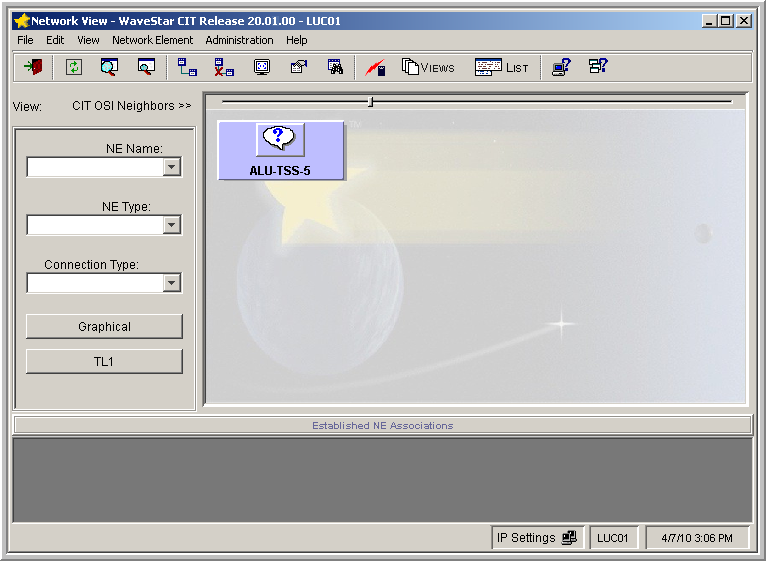
From the View: pull-down menu, select CIT OSI Neighbors. Note: This View: is not the menu bar item View →...; it is located above the NE Name pull-down menu. Result: The CIT OSI Neighbor(s) is automatically detected. The resulting NE icon also provides a visual confirmation of the NE's TID. In all cases, the default user ID and password for Alcatel-Lucent 1850 TSS-5 will be used to log in to the NE. If you were previously logged in to the NE and/or you do not see your NE, from the Network View, select View → Refresh OSI View.  If your SYSCTL was not factory-fresh and you do not see your NE in the Network View, it is possible that OSI was previously disabled on LAN-1. Proceed to Procedure 6-3.5: Log in serially and enable FTP and/or OSI on the LAN port to log in and enable OSI. | ||||||||
8 |
Use the following table to determine the TID of the replacement SYSCTL and the source of the select provisionable parameters that are available while the SYSCTL is in the factory-fresh state. The first wizard screen in Step 11 confirms the boot code of you replacement SYSCTL.
Notes:
| ||||||||
9 |
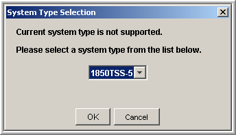
In the Network View, right-click on the NE icon that was detected in Step 7 and select Graphical Using → OSI from the resulting menu. Result: The System Type Selection window appears.  | ||||||||
10 |
In the System Type Selection window, select 1850TSS-5 and click OK. Result: The NE Login Dialog window appears. | ||||||||
11 |
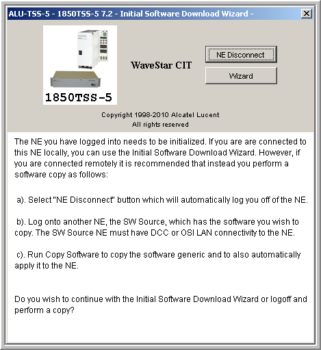
Enter the following default login/password in NE Login Dialog window (login information is case sensitive) to log in to the NE. User ID: ALU01 Password: 1850TSS-5 Click OK. Important! While the SYSCTL is in the factory-fresh state, user ID/password provisioning is NOT uploaded from the Main circuit pack. Therefore, you must log in to a factory-fresh SYSCTL using the defaults listed above. After the generic is downloaded and applied, and the NE resets, all previously provisioned user IDs/passwords are restored and must be used to log in to the NE. Result: The following window appears. The boot code of your SYSCTL appears in the title bar after 1850TSS-5. The figure below indicates that the SYSCTL has 7.2 boot code. Your boot code may be different.  | ||||||||
12 |
Referring to the title bar of the screen illustrated in Step 11, what is the boot code of your SYSCTL (VLNC2)?
| ||||||||
13 |
To verify that you can log into the NE, connect the cross-over LAN cable from the PC's Network Interface Card (NIC) to the LAN port and establish a WaveStar® CIT session. Reference: Procedure 6-2: Connect personal computer (PC) and establish WaveStar® CIT session | ||||||||
14 |
Specifying OSI in the Connection Type: field, log in to the shelf. Important! Your TID, user ID, and password are no longer default. ALL user-provisioned parameters (except circuit IDs) are restored from the Main VLNC5x after the software applied and the shelf reset. Log in to the shelf using your original user ID and password. Result: The title bar of the System View reflects the current NE software generic, (for example, 7.2.2). | ||||||||
15 |
Were you able to log into the shelf?
| ||||||||
16 |
Did you have circuit IDs provisioned prior to the replacement?
End of steps |