Common Configuration Tasks
The following basic system tasks are performed, as required:
Configuring Cards and Adapter Cards
This section contains the following topics:
Configuring Cards
Card configurations must include a chassis slot designation. A slot must be preconfigured with the type of card and adapter cards that are allowed to be provisioned.
The mda-mode command is used on the following adapter cards to configure the appropriate encapsulation methods (cem-atm-ppp or cem-fr-hdlc-ppp) that are required to support pseudowire services:
4-port DS3/E3 Adapter card
16-port T1/E1 ASAP Adapter card
32-port T1/E1 ASAP Adapter card
The mda-mode command is used on the 10-port 1GigE/1-port 10GigE X-Adapter card to configure the card for either 10-port 1GigE mode or 1-port 10GigE mode (x10-1gb-sfp or x1-10gb-sf+).
The mda-mode command is used on the 4-port OC3/STM1 / 1-port OC12/STM4 Adapter card to configure the card for either 4-port OC3/STM1 mode or 1-port OC12/STM4 mode (p4-oc3 or p1-oc12).
The mda-mode command is used on the Integrated Services card to configure the card for a SCADA application: (mddb, pcm, or vcb).
The following CLI syntax shows an example of configuring a chassis slot and card (to activate the IOM) and adapter cards on the 7705 SAR-8 Shelf V2.
- Example:
NOK-1>config# card 1NOK-1>config>card# card-type iom-sarNOK-1>config>card# mda 1NOK-1>config>card>mda# mda-type a6-emNOK-1>config>card>mda# exitNOK-1>config>card# mda 2NOK-1>config>card>mda# mda-type a4-oc3NOK-1>config>card>mda# exitNOK-1>config>card# mda 3NOK-1>config>card>mda# mda-type a16-chds1v2NOK-1>config>card>mda# exitNOK-1>config>card# mda 4NOK-1>config>card>mda# mda-type a4-chds3v2NOK-1>config>card>mda# mda-mode cem-fr-hdlc-pppNOK-1>config>card>mda# exitNOK-1>config>card# mda 5NOK-1>config>card>mda# mda-type a8-1gb-sfpNOK-1>config>card>mda# exitNOK-1>config>card# mda 6NOK-1>config>card>mda# mda-type a2-choc3NOK-1>config>card>mda# exitNOK-1>config>card# exit
The following CLI syntax shows an example of configuring a chassis slot and card (to activate the IOM) and adapter cards on the 7705 SAR-18.
- Example:
NOK-1>config# card 1NOK-1>config>card# card-type iom-sarNOK-1>config>card# mda 1NOK-1>config>card>mda# mda-type aux-alarmNOK-1>config>card>mda# exitNOK-1>config>card# mda 2NOK-1>config>card>mda# mda-type a8-1gb-sfpNOK-1>config>card>mda# exitNOK-1>config>card# mda 2NOK-1>config>card>mda# mda-type a8-1gb-sfpNOK-1>config>card>mda# exitNOK-1>config>card# mda 3NOK-1>config>card>mda# mda-type a8-1gb-sfpNOK-1>config>card>mda# exitNOK-1>config>card# mda 4NOK-1>config>card>mda# mda-type a8-1gb-sfpNOK-1>config>card>mda# exitNOK-1>config>card# mda 5NOK-1>config>card>mda# mda-type a8-1gb-sfpNOK-1>config>card>mda# exitNOK-1>config>card# mda 6NOK-1>config>card>mda# mda-type a32-chds1v2NOK-1>config>card>mda# mda-mode cem-atm-pppNOK-1>config>card>mda# exitNOK-1>config>card# mda 7NOK-1>config>card>mda# mda-type a32-chds1v2NOK-1>config>card>mda# mda-mode cem-atm-pppNOK-1>config>card>mda# exitNOK-1>config>card# mda 8NOK-1>config>card>mda# mda-type a32-chds1v2NOK-1>config>card>mda# mda-mode cem-atm-pppNOK-1>config>card>mda# exitNOK-1>config>card# mda 9NOK-1>config>card>mda# mda-type a32-chds1v2NOK-1>config>card>mda# mda-mode cem-atm-pppNOK-1>config>card>mda# exitNOK-1>config>card# mda 10NOK-1>config>card>mda# mda-type a4-oc3NOK-1>config>card>mda# exitNOK-1>config>card# mda 11NOK-1>config>card>mda# mda-type a4-chds3v2NOK-1>config>card>mda# mda-mode cem-fr-hdlc-pppNOK-1>config>card>mda# exitNOK-1>config>card# mda 12NOK-1>config>card>mda# exitNOK-1>config>card# mda X1NOK-1>config>card>mda# mda-type x-10GigE-v2NOK-1>config>card>mda# mda-mode x1-10gb-sf+NOK-1>config>card>mda# exitNOK-1>config>card# mda X2NOK-1>config>card>mda# mda-type x-10GigE-v2NOK-1>config>card>mda# mda-mode x10-1gb-sfpNOK-1>config>card>mda# exitNOK-1>config>card# mda X3NOK-1>config>card>mda# mda-type x-10GigE-v2NOK-1>config>card>mda# mda-mode x1-10gb-sf+NOK-1>config>card>mda# exitNOK-1>config>card# mda X4NOK-1>config>card>mda# mda-type x-10GigE-v2NOK-1>config>card>mda# mda-mode x10-1gb-sfpNOK-1>config>card>mda# exitNOK-1>config>card# exit
Configuring Adapter Card Network Queue QoS Policies
Network queue QoS policies can optionally be applied to adapter cards. Network queue policies define the ingress network queuing at the adapter card node level. Network queue policy parameters are configured in the config>qos context. For more information about network queue policies, see the 7705 SAR Quality of Service Guide, ‟Network Queue QoS Policies”.
Queue policies do not apply to the Auxiliary Alarm card.
Use the following CLI syntax to configure network queue policies on an adapter card.
- CLI Syntax:
config>card>mda#networkingressqueue-policy nameno shutdownno shutdown
Configuring Ring Adapter Card or Module Network and Network Queue QoS Policies
Network and network queue QoS policies can optionally be applied to a ring adapter card or module, such as the 2-port 10GigE (Ethernet) Adapter card or 2-port 10GigE (Ethernet) module.
Network policies define ring type network policies to a ring adapter card, where a ring type is a network-policy-type. Network queue policies define the add/drop port network queuing at the adapter card node level.
Network and network queue policy parameters are configured in the config>qos context. For more information about network queue policies, see the 7705 SAR Quality of Service Guide, ‟Network QoS Policies” and ‟Network Queue QoS Policies”.
Use the following CLI syntax to configure network and network queue policies on an adapter card.
- CLI Syntax:
config>card>mda#networkringadd-drop-port-queue-policy nameqos-policy network-policy-idno shutdown
Configuring Adapter Card Fabric Statistics
The collection of fabric statistics can be enabled on an adapter card to report about the fabric traffic flow and potential discards.
Fabric statistics do not apply to the Auxiliary Alarm card.
Use the following syntax to configure fabric statistics on an adapter card.
- CLI Syntax:
config>card>mda#[no] fabric-stats-enabled
Configuring Adapter Card Fabric Profile
Ingress fabric profiles can be configured on an adapter card, in either a network or access context, to allow network ingress to fabric shapers to be user-configurable at rates that provide up to 1 Gb/s switching throughput from the adapter card toward the fabric. For more information about fabric profiles, see the 7705 SAR Quality of Service Guide, ‟QoS Fabric Profiles”.
Fabric profiles do not apply to the Auxiliary Alarm card.
Use the following CLI syntax to assign a fabric profile on an adapter card.
- CLI Syntax:
config>card>mda#mda-type type[no] fabric-stats-enablednetworkingressfabric-policy fabric-policy-idqueue-policy nameaccessingressfabric-policy fabric-policy-idno shutdown
Configuring Adapter Card Clock Mode
Clocking mode is defined at the adapter card level. There are three clocking modes available: differential, adaptive, and dcr-acr, which is a mixture of both differential and adaptive. The dcr-acr option enables differential and adaptive clocking on different ports of the same card or chassis. Differential and dcr-acr clocking modes also support a configurable timestamp frequency. To carry differential clock recover information, the RTP header must be enabled on the SAP.
The following chassis, cards, and modules support all clocking modes:
16-port T1/E1 ASAP Adapter card
32-port T1/E1 ASAP Adapter card
7705 SAR-M (variants with T1/E1 ports)
7705 SAR-X
7705 SAR-A (variant with T1/E1 ports)
T1/E1 ports on the 4-port T1/E1 and RS-232 Combination module
When the timestamp frequency is configured for differential or dcr-acr mode on a 4-port T1/E1 and RS-232 Combination module, the configured value takes effect on both modules installed in the 7705 SAR-H.
The following cards support differential clocking mode only:
4-port OC3/STM1 / 1-port OC12/STM4 Adapter card (DS1/E1 channels)
4-port DS3/E3 Adapter card (clear channel DS3/E3 ports and DS1/E1 channels on channelized DS3 ports (E3 ports cannot be channelized)); differential clocking mode on DS1/E1 channels is supported only on the first three ports of the card
Use the following CLI syntax to configure adaptive clocking mode.
- CLI Syntax:
config>card>mda#clock-mode adaptiveno shutdown
Use the following CLI syntax to configure differential clocking mode or a combination of differential and adaptive clocking modes with a timestamp frequency.
- CLI Syntax:
config>card>mda#clock-mode {differential | dcr-acr} [timestamp-freq {19440 | 25000 | 77760 | 103680}]no shutdown
Configuring Adapter Card Voice Attributes
Use the following CLI syntax to assign the type of companding law and signaling to be used on a 6-port E&M Adapter card installed in a 7705 SAR-8 Shelf V2 or 7705 SAR-18 chassis.
- CLI Syntax:
config>card>mda#mda-type a6-emvoicecompanding-law {a-law | mu-law}signaling-type {type-1 | type-2 | type-v}no shutdown
Use the following CLI syntax to assign the type of companding law to be used on the FXO and FXS ports on an 8-port Voice & Teleprotection card installed in a 7705 SAR-8 Shelf V2 or 7705 SAR-18 chassis.
- CLI Syntax:
config>card>mda#mda-type a8-vtvoicecompanding-law {a-law | mu-law}no shutdown
Use the following CLI syntax to assign the type of companding law to be used on the FXO ports on an 8-port FXO Adapter card installed in a 7705 SAR-8 Shelf V2 or 7705 SAR-18 chassis.
- CLI Syntax:
config>card>mda#mda-type a8-fxovoicecompanding-law {a-law | mu-law}no shutdown
Use the following CLI syntax to assign the type of companding law to be used on the FXS ports on a 6-port FXS Adapter card installed in a 7705 SAR-8 Shelf V2 or 7705 SAR-18 chassis.
- CLI Syntax:
config>card>mda#mda-type a6-fxsvoicecompanding-law {a-law | mu-law}no shutdown
Configuring Ring Adapter Card or Module Parameters
Use the following CLI syntax to configure the adapter card or module parameters on the 2-port 10GigE (Ethernet) Adapter card or 2-port 10GigE (Ethernet) module.
- CLI Syntax:
config>card>mda#ring[no] disable-aging[no] disable-learning[no] discard-unknown-sourcefdb-table-high-wmark high-water-markno fdb-table-high-wmarkfdb-table-size table-sizeno fdb-table-size[no] mac-pinning port port-idremote-age aging-timerno remote-age[no] static-mac mac ieee-address port port-id [create][no] shutdown
After configuring the adapter card or module, you can use the config>card>mda>ring>info detail command to display the information on the ring adapter card or module.
*A:7705:Sar18>config>card>mda>ring# info detail
----------------------------------------------
                no disable-aging
                no disable-learning
                no discard-unknown-source
                no remote-age
                no fdb-table-size
                no fdb-table-high-wmark
                no mac-pinning port 1/11/1
                no mac-pinning port 1/11/2
----------------------------------------------
*A:7705:Sar18>config>card>mda>ring#
Configuring Auxiliary Alarm Card, Chassis, and Ethernet Port External Alarm Parameters
Use the following CLI syntax to configure the external alarm parameters for the Auxiliary Alarm card, 7705 SAR Ethernet ports (supported on all platforms with Ethernet ports), and for the four alarm inputs on the fan module (for the 7705 SAR-8 Shelf V2), alarm connector (for the 7705 SAR-M, 7705 SAR-Wx, 7705 SAR-H, 7705 SAR-Hc, and 7705 SAR-X), and alarm module (for the 7705 SAR-18).
The output commands apply to the Auxiliary Alarm card only. The debounce and normally commands do not apply to external alarm parameters configured on an Ethernet port.
- CLI Syntax:
config# external-alarmsalarm alarm-idchassis-alarmingdescription description-stringlogseverity {critical | major | minor | warning}thresholdsanaloglevel {lt | gt} millivoltsexittrigger [any | all] {alarm-input1 | alarm-input2... | alarm-input8}exitinput alarm-inputdebounce secondsdebounce detect detect-seconds clear clear-secondsdescription description-stringname name-stringnormally {open | closed}shutdownexitoutput alarm-outputdescription description-stringname name-stringshutdown
- Example:
config# external-alarms input alarm.d-1config# external-alarms input alarm.d-2config# external-alarms input alarm.d-3config# external-alarms input alarm.d-4config# external-alarms input alarm-1/1.d-1 name dinput1config# external-alarms input alarm-1/1.d-2 name dinput2config# external-alarms input alarm-1/1.d-3 name dinput3config# external-alarms input alarm-1/1.d-4 name dinput4config# external-alarms input alarm-1/1.d-5 name dinput5config# external-alarms input alarm-1/1.d-23 name dinput23config# external-alarms input alarm-1/1.d-24 name dinput24config# external-alarms output alarm-1/1.d-1 name dinput11config# external-alarms output relay-1/1.d-2 name output2config# external-alarms output relay-1/1.d-3 name output3config# external-alarms output relay-1/1.d-4 name output4config# external-alarms output relay-1/1.d-5 name output5config# external-alarms output relay-1/1.d-2 name output2config# external-alarms output relay-1/1.d-3 name output3config# external-alarms output relay-1/1.d-4 name output4config# external-alarms output relay-1/1.d-5 name output5config>ext-alarms# alarm 1config>ext-alarms>alarm# chassis-alarmingconfig>ext-alarms>alarm# logconfig>ext-alarms>alarm# trigger all alarm-1/1.d-1 alarm-1/1.d-2 alarm-1/1.d-3 alarm-1/1.d-4 alarm-1/1.d-5 alarm-1/1.a-1config>ext-alarms>alarm# exitconfig>ext-alarms# alarm 2config>ext-alarms>alarm# chassis-alarmingconfig>ext-alarms>alarm# no logconfig>ext-alarms>alarm# trigger all alarm-1/1.d-1 alarm-1/1.d-2 alarm-1/1.d-3 alarm-1/1.d-4 alarm-1/1.d-23 alarm-1/1.d-24 alarm-1/1.a-1 alarm-1/1.a-2config>ext-alarms>alarm# exitconfig>ext-alarms# alarm 3config>ext-alarms>alarm# chassis-alarmingconfig>ext-alarms>alarm# logconfig>ext-alarms>alarm# trigger any alarm-1/1.d-1 alarm-1/1.d-2 alarm-1/1.d-3 alarm-1/1.d-4 alarm-1/1.d-5 alarm-1/1.a-1 alarm-1/1.a-2 alarm.d-1 alarm.d-2config>ext-alarms>alarm# exitconfig>ext-alarms# alarm 4config>ext-alarms>alarm# chassis-alarmingconfig>ext-alarms>alarm# logconfig>ext-alarms>alarm# trigger any alarm-1/1.a-1 alarm-1/1.a-2 alarm.d-1 alarm.d-2 alarm.d-3 alarm.d-4config>ext-alarms>alarm# severity majorconfig>ext-alarms>alarm# thresholdsconfig>ext-alarms>alarm>thresholds# analog level lt 4config>ext-alarms>alarm>thresholds# exitconfig>ext-alarms>alarm# exitconfig>ext-alarms# exit
The following CLI syntax shows an example of configuring custom alarms on Ethernet ports.
- Example:
config# external-alarms input port-1/1/5config>ext-alarms>in# name ‟CABINET-DOOR”config>ext-alarms>in# description ‟Front Panel Access Door Sensor”config>ext-alarms>in# exitconfig# external-alarms input port-1/1/6config>ext-alarms>in# name ‟REAR-PANEL”config>ext-alarms>in# description ‟Rear Maintenance Panel Sensor”config>ext-alarms>in# exitconfig# external-alarms alarm 1config>ext-alarms>alarm# description ‟Local Security Breach”config>ext-alarms>alarm# trigger ‟CABINET-DOOR” ‟REAR-PANEL”config>ext-alarms>alarm# severity criticalconfig>ext-alarms>alarm# no shutdownconfig>ext-alarms>alarm# exit
Use the show external-alarms input command to display Ethernet port alarm input information.
*NOK-A# show external-alarms input
===========================================================================
External Alarm Input Summary
===========================================================================
Input Id        Name            Type        Admin Value     Alarm State
---------------------------------------------------------------------------
alarm.d-1                       Digital-In  Up     Open      Ok
alarm.d-2                       Digital-In  Up     Open      Ok
alarm.d-3                       Digital-In  Up     Open      Ok
alarm.d-4                       Digital-In  Up     Open      Ok
port-1/5/1      CABINET-DOOR    Oper-State  Up     Down      Alarm-Detected
port-1/6/1      REAR-PANEL      Oper-State  Up     Up        Ok
===========================================================================
Displaying Adapter Card Information
After performing the adapter card configuration, you can use the config>card 1 and the info commands to display the information on the 7705 SAR-8 Shelf V2.
NOK-1>config# card 1
NOK-1>config>card# info
#--------------------------------------------------
echo "Card Configuration"
#--------------------------------------------------
    card 1
        card-type iom-sar
        mda 1
            mda-type a6-em
        exit
        mda 2
            mda-type a4-oc3
        exit
        mda 3
            mda-type a16-chds1v2
        exit
        mda 4
            mda-type a4-chds3v2
        exit
        mda 5
            mda-type a8-1gb-sfp
        exit
        mda 6
            mda-type a2-choc3
        exit
    exit
#--------------------------------------------------
.....
NOK-1> config#
Use the config>card 1 and the info detail commands to display the adapter card detailed configuration information on the 7705 SAR-8 Shelf V2.
NOK-1>config# card 1
NOK-1>config>card# info detail
#--------------------------------------------------
echo "Card Configuration"
#--------------------------------------------------
card 1
        card-type iom-sar
        mda 1
            mda-type a6-em
            voice
                companding-law a-law
                signaling-type type-v
            exit
            no shutdown
        exit
        mda 2
            mda-type a4-oc3
            no fabric-stats-enabled
            network
                ingress
                    fabric-policy 1
                    queue-policy "default"
                exit
            exit
            access
                ingress
                    fabric-policy 1
                exit
            exit
            no shutdown
        exit
        mda 3
            mda-type a16-chds1v2
            clock-mode adaptive
            no fabric-stats-enabled
            network
                ingress
                    fabric-policy 1
                    queue-policy "default"
                exit
            exit
            access
                ingress
                    fabric-policy 1
                exit
            exit
            no shutdown
        exit
        mda 4
            no shutdown
            mda-type a4-chds3v2
            no fabric-stats-enabled
            network
                ingress
                    fabric-policy 1
                    queue-policy "default"
                exit
            exit
            access
                ingress
                    fabric-policy 1
                exit
            exit
        exit
        mda 5
            mda-type a8-1gb-sfp
            no fabric-stats-enabled
            network
                ingress
                    fabric-policy 1
                    queue-policy "default"
                exit
            exit
            access
                ingress
                    fabric-policy 1
                exit
            exit
            no shutdown
        exit
        mda 6
            mda-type a2-choc3
            clock-mode adaptive
            no fabric-stats-enabled
            network
                ingress
                    fabric-policy 1
                    queue-policy "default"
                exit
            exit
            access
                ingress
                    fabric-policy 1
                exit
            exit
            no shutdown
        exit
        no shutdown
    exit
#-------------------------------------------------
......
NOK-1> config#
Configuring Ports
This section provides the CLI syntax and examples to configure the following:
Configuring APS Port Parameters
APS has the following configuration rules.
A working port must be added first. Then a protection port can be added or removed at any time.
The protection port must be removed from the configuration before the working port is removed.
A protection port or working port must be shut down in the config>port port-id context before being removed from an APS group.
A path cannot be configured on a port before the port is added to an APS group.
A working port cannot be removed from an APS group until the APS port path is removed.
When ports are added to an APS group, all path-level configurations are available only at the APS port level and configuration on the physical member ports is blocked.
When a port is a protection circuit of an APS group, the configuration options available in the config>port port-id>sonet-sdh context are not allowed for that port unless they are in the following exception list:
clock-source
[no] loopback
[no] report-alarm
section-trace
[no] threshold
SC-APS is supported in unidirectional or bidirectional mode on:
2-port OC3/STM1 Channelized Adapter cards for TDM CES (Cpipes) and TDM CESoETH with MEF 8 with DS3/DS1/E1/DS0 channels
4-port OC3/STM1 / 1-port OC12/STM4 Adapter cards for MLPPP access ports or TDM CES (Cpipes) and TDM CESoETH (MEF 8) access ports with DS1/E1 channels, or on a network port configured for POS
4-port OC3/STM1 Clear Channel Adapter cards network side (configured for POS operation).
SC-APS with TDM access is supported on DS3, DS1, E1, and DS0 (64 kb/s) channels.
MC-APS is supported in bidirectional mode on:
2-port OC3/STM1 Channelized Adapter cards for TDM CES (Cpipes) and TDM CESoETH with MEF 8 with DS3/DS1/E1/DS0 channels
4-port OC3/STM1 / 1-port OC12/STM4 Adapter cards for MLPPP access ports or CES (Cpipes) and TDM CESoETH (MEF 8) access ports with DS1/E1 channels.
MC-APS with TDM access is supported on DS3, DS1, E1, and DS0 (64 kb/s) channels. TDM SAP-to-SAP with MC-APS is not supported.
APS can be configured in SC-APS mode with both working and protection circuits on the same node, or in MC-APS mode with the working and protection circuits configured on separate nodes.
For SC-APS and MC-APS with MEF 8 services where the remote device performs source MAC validation, the MAC address of the channel group in each of the redundant interfaces may be configured to the same MAC address using the mac CLI command.
Use the following CLI syntax to configure APS port parameters for an SC-APS group.
- CLI Syntax:
config# port aps-idapshold-time-aps {[lsignal-fail sf-time] [lsignal-degrade sd-time]}protect-circuit port-idrdi-alarms {suppress | circuit}revert-time minutesswitching-mode {bi-directional | uni-1plus1}working-circuit port-id
The following CLI syntax shows an example of configuring ports for SC-APS. The only mandatory configuration required to create an SC-APS group is to configure the working and protection circuit.
- Example:
config# port aps-1config>port# apsconfig>port>aps# switching-mode uni-1plus1config>port>aps# working-circuit 1/2/4config>port>aps# rdi-alarms circuitconfig>port>aps# revert-time 5config>port>aps# protect-circuit 1/3/4
Use the config port info command to display port configuration information.
ALU-B>config>port# info
             -------------------------------------------------
                       shutdown
                       aps
                       switching-mode uni-1plus1
                       revert-time 5
                       working-circuit 1/2/4
                       protect-circuit 1/3/4
                       exit
                       sonet-sdh
                       exit
             -------------------------------------------------
Use the following CLI syntax to configure APS port parameters for an MC-APS group.
- CLI Syntax:
config# port aps-idapsadvertise-interval advertise-intervalhold-time hold-timeneighbor ip-addressprotect-circuit port-idrdi-alarms {suppress | circuit}revert-time minutesworking-circuit port-id
The following CLI syntax shows an example of configuring an MC-APS working circuit on a node. The only mandatory configuration required to create an MC-APS group is to configure the working and protection circuit, and the neighbor address.
- Example:
config# port aps-2config>port# apsconfig>port>aps# advertise-interval 25config>port>aps# hold-time 75config>port>aps# working-circuit 1/2/4config>port>aps# neighbor 10.10.10.101config>port>aps# rdi-alarms circuitconfig>port>aps# revert-time 5
To complete the MC-APS configuration, log on to the protection node, configure an APS group with the same APS ID as the working group, and configure the protection circuit. The MC-APS signaling path is established automatically when APS groups with matching IDs are both configured.
The following CLI syntax shows an example of configuring an MC-APS protection circuit on a node.
- Example:
config# port aps-2config>port# apsconfig>port>aps# protect-circuit 1/3/2
Use the config port info command to display port configuration information.
*A:7705:Dut-D# configure port aps-2
*A:7705:Dut-D>config>port# info
----------------------------------------------
        aps
            neighbor 10.10.10.2
            protect-circuit 1/3/2
        exit
        sonet-sdh
            path sts1-1
                payload vt15
                no shutdown
            exit
            path vt15-1.1.1
                no shutdown
            exit
        exit
        tdm
            ds1 1.1.1
                channel-group 1
                    encap-type cem
                    timeslots 1-24
                    no shutdown
                exit
                no shutdown
            exit
        exit
        no shutdown
----------------------------------------------
SC-APS and MC-APS on the 2-port OC3/STM1 Channelized Adapter card (access side) normally support only TDM CES (Cpipes). SC-APS and MC-APS support Epipes with TDM SAPs when the MEF 8 service is used.
The following CLI syntax shows an example of TDM CESoETH with MEF 8 for APS.
*A:7705:Dut-D# configure service epipe 1
*A:7705:Dut-D>config>epipe# info
----------------------------------------------
epipe 1 customer 1 vpn 1 create
            description "Default epipe description for service id 1"
            endpoint "X" create
            exit
            endpoint "Y" create
            exit
            sap aps-1.1.1.1.1 endpoint "X" create
                description "Default sap description for service id 1"
                cem
                    local-ecid 1
                    remote-ecid 2
                    remote-mac a4:8d:01:06:00:01
                exit
            exit
            spoke-sdp 2003:1 endpoint "Y" create
            exit
            spoke-sdp 2004:1001 endpoint "X" icb create
            exit
            spoke-sdp 2004:2001 endpoint "Y" icb create
            exit
            no shutdown
        exit
----------------------------------------------
The following CLI syntax shows examples of typical configurations of SC-APS and MC-APS on MC-MLPPP access ports on a 4-port OC3/STM1 / 1-port OC12/STM4 Adapter card.
SC-APS node:
===================
    port bpgrp-ppp-1
        multilink-bundle
            working-bundle bundle-ppp-1/5.1
            protect-bundle bundle-ppp-1/6.1
        exit
    exit

   port aps-1
        aps
            working-circuit 1/5/1
            protect-circuit 1/6/4
        exit
        sonet-sdh
            path sts1-1
                no shutdown
            exit
            path vt15-1.1.1
                no shutdown
            exit
            path vt15-1.1.2
                no shutdown
            exit
            path vt15-1.1.3
                no shutdown
            exit
            path vt15-1.1.4
                no shutdown
            exit
            path vt15-1.2.1
                no shutdown
            exit
            path vt15-1.2.2
                no shutdown
            exit
            path vt15-1.2.3
                no shutdown
            exit
            path vt15-1.2.4
                no shutdown
            exit
        tdm
            ds1 1.1.1
                channel-group 1
                    encap-type ipcp
                    no shutdown
                exit
                no shutdown
            exit
            ds1 1.1.2
                channel-group 1
                    encap-type ipcp
                    no shutdown
                exit
                no shutdown
            exit
            ds1 1.1.3
                channel-group 1
                    encap-type ipcp
                    no shutdown
                exit
                no shutdown
            exit
            ds1 1.1.4
                channel-group 1
                    encap-type ipcp
                    no shutdown
                exit
                no shutdown
            exit
            ds1 1.2.1
               channel-group 1
                    encap-type ipcp
                    no shutdown
                exit
                no shutdown
            exit
            ds1 1.2.2
                channel-group 1
                    encap-type ipcp
                   no shutdown
                exit
                no shutdown
            exit
            ds1 1.2.3
                channel-group 1
                    encap-type ipcp
                    no shutdown
                exit
                no shutdown
            exit
            ds1 1.2.4
                channel-group 1
                    encap-type ipcp
                    no shutdown
                exit
                no shutdown
            exit

     port bpgrp-ppp-1
        multilink-bundle
            mlppp
                endpoint-discriminator class ip-address discriminator-id 1.2.3.4
                multiclass 4
            exit
            member aps-1.1.1.1.1
            member aps-1.1.1.2.1
            member aps-1.1.1.3.1
            member aps-1.1.1.4.1
            member aps-1.1.2.1.1
            member aps-1.1.2.2.1
            member aps-1.1.2.3.1
            member aps-1.1.2.4.1
        exit
        no shutdown
    exit
    port bundle-ppp-1/5.1
        no shutdown
    exit
    port bundle-ppp-1/6.1
        no shutdown
    exit
    service
        customer 1 create
            description "Default customer"
        exit
        ipipe 1 customer 1 vpn 1 create
            description "Default ipipe description for service id 1"
            sap 1/2/8:501 create
                description "Default sap description for service id 1"
                ce-address 172.16.0.1
            exit
            sap bpgrp-ppp-1 create
                description "Default sap description for service id 1"
                ce-address 172.16.0.0
                ipcp
                exit
            exit
            no shutdown
        exit
MC-APS working node:
===========================
    port bpgrp-ppp-1
        multilink-bundle
            working-bundle bundle-ppp-1/9.1
        exit
    exit
     port aps-1
        aps
            neighbor 10.10.10.4
            working-circuit 1/9/2
        exit
        sonet-sdh
            path sts1-1
                no shutdown
            exit
            path vt15-1.1.1
                no shutdown
            exit
            path vt15-1.1.2
                no shutdown
            exit
            path vt15-1.1.3
                no shutdown
            exit
            path vt15-1.1.4
                no shutdown
            exit
            path vt15-1.2.1
                no shutdown
            exit
            path vt15-1.2.2
                no shutdown
            exit
            path vt15-1.2.3
                no shutdown
            exit
            path vt15-1.2.4
                no shutdown
            exit
        tdm
            ds1 1.1.1
                channel-group 1
                    encap-type ipcp
                    no shutdown
                exit
                no shutdown
            exit
            ds1 1.1.2
                channel-group 1
                    encap-type ipcp
                    no shutdown
                exit
                no shutdown
            exit
            ds1 1.1.3
                channel-group 1
                    encap-type ipcp
                    no shutdown
                exit
                no shutdown
           exit
            ds1 1.1.4
                channel-group 1
                    encap-type ipcp
                    no shutdown
                exit
                no shutdown
            exit
            ds1 1.2.1
                channel-group 1
                    encap-type ipcp
                    no shutdown
                exit
                no shutdown
            exit
            ds1 1.2.2
                channel-group 1
                    encap-type ipcp
                    no shutdown
                exit
                no shutdown
            exit
            ds1 1.2.3
                channel-group 1
                    encap-type ipcp
                    no shutdown
                exit
                no shutdown
            exit
            ds1 1.2.4
                channel-group 1
                    encap-type ipcp
                    no shutdown
                exit
                no shutdown
            exit
    port bpgrp-ppp-1
        multilink-bundle
            mlppp
                endpoint-discriminator class ip-address discriminator-id 1.2.3.4
                multiclass 4
            exit
            member aps-1.1.1.1.1
            member aps-1.1.1.2.1
            member aps-1.1.1.4.1
            member aps-1.1.1.3.1
            member aps-1.1.2.1.1
            member aps-1.1.2.2.1
            member aps-1.1.2.3.1
            member aps-1.1.2.4.1
        exit
        no shutdown
    exit
    port bundle-ppp-1/9.1
        no shutdown
    exit
    service
        sdp 3001 create
            description "LDP_SdpToDut-A"
            far-end 10.10.10.1
            ldp
            keep-alive
                shutdown
            exit
            no shutdown
        exit
        sdp 3004 create
            description "LDP_SdpToDut-D"
            far-end 10.10.10.4
            ldp
            keep-alive
                shutdown
            exit
            no shutdown
        exit
        customer 1 create
            description "Default customer"
        exit
        ipipe 1 customer 1 vpn 1 create
            description "Default ipipe description for service id 1"
            endpoint "X" create
            exit
            endpoint "Y" create
            exit
            sap bpgrp-ppp-1 endpoint "X" create
                description "Default sap description for service id 1"
                ce-address 172.16.0.1
                ipcp
                exit
            exit
            spoke-sdp 3001:1 endpoint "Y" create
                ce-address 172.16.0.0
                no shutdown
            exit
            spoke-sdp 3004:1001 endpoint "X" icb create
                no shutdown
            exit
            spoke-sdp 3004:2001 endpoint "Y" icb create
                no shutdown
            exit
            no shutdown
        exit
MC-APS protection node:
===========================
    port bpgrp-ppp-1
        multilink-bundle
            protect-bundle bundle-ppp-1/9.1
        exit
    exit
    port aps-1
        aps
            neighbor 10.10.10.3
            protect-circuit 1/9/4
        exit
        sonet-sdh
            path sts1-1
                no shutdown
            exit
            path vt15-1.1.1
                no shutdown
            exit
            path vt15-1.1.2
                no shutdown
            exit
            path vt15-1.1.3
                no shutdown
            exit
            path vt15-1.1.4
                no shutdown
            exit
            path vt15-1.2.1
                no shutdown
            exit
            path vt15-1.2.2
                no shutdown
            exit
            path vt15-1.2.3
                no shutdown
            exit
            path vt15-1.2.4
                no shutdown
            exit
        tdm
            ds1 1.1.1
                channel-group 1
                    encap-type ipcp
                    no shutdown
                exit
                no shutdown
            exit
            ds1 1.1.2
                channel-group 1
                    encap-type ipcp
                    no shutdown
                exit
                no shutdown
            exit
            ds1 1.1.3
                channel-group 1
                    encap-type ipcp
                    no shutdown
                exit
                no shutdown
            exit
            ds1 1.1.4
                channel-group 1
                    encap-type ipcp
                    no shutdown
                exit
                no shutdown
            exit
            ds1 1.2.1
                channel-group 1
                    encap-type ipcp
                    no shutdown
                exit
                no shutdown
            exit
            ds1 1.2.2
                channel-group 1
                    encap-type ipcp
                    no shutdown
                exit
                no shutdown
            exit
            ds1 1.2.3
                channel-group 1
                    encap-type ipcp
                    no shutdown
                exit
                no shutdown
            exit
            ds1 1.2.4
                channel-group 1
                    encap-type ipcp
                    no shutdown
                exit
                no shutdown
            exit
    port bpgrp-ppp-1
        multilink-bundle
            mlppp
                endpoint-discriminator class ip-address discriminator-id 1.2.3.4
                multiclass 4
            exit
            member aps-1.1.1.1.1
            member aps-1.1.1.2.1
            member aps-1.1.1.3.1
            member aps-1.1.1.4.1
            member aps-1.1.2.1.1
            member aps-1.1.2.2.1
            member aps-1.1.2.3.1
            member aps-1.1.2.4.1
        exit
        no shutdown
    exit
    port bundle-ppp-1/9.1
        no shutdown
    exit
    service
        sdp 4001 create
            description "LDP_SdpToDut-A"
            far-end 10.10.10.1
            ldp
            keep-alive
                shutdown
            exit
            no shutdown
        exit
        sdp 4003 create
            description "LDP_SdpToDut-C"
            far-end 10.10.10.3
            ldp
            keep-alive
                shutdown
            exit
            no shutdown
        exit
        customer 1 create
            description "Default customer"
        exit
        ipipe 1 customer 1 vpn 1 create
            description "Default ipipe description for service id 1"
            endpoint "X" create
            exit
            endpoint "Y" create
            exit
            sap bpgrp-ppp-1 endpoint "X" create
                description "Default sap description for service id 1"
                ce-address 172.16.0.1
                ipcp
                exit
            exit
            spoke-sdp 4001:1 endpoint "Y" create
                ce-address 172.16.0.0
                no shutdown
            exit
            spoke-sdp 4003:1001 endpoint "Y" icb create
                no shutdown
            exit
            spoke-sdp 4003:2001 endpoint "X" icb create
                no shutdown
            exit
            no shutdown
        exit
Pseudowire redundancy node:
===================
    service
        sdp 1003 create
            description "LDP_SdpToDut-C"
            far-end 10.10.10.3
            ldp
            keep-alive
                shutdown
            exit
            no shutdown
        exit
        sdp 1004 create
            description "LDP_SdpToDut-D"
            far-end 10.10.10.4
            ldp
            keep-alive
                shutdown
            exit
            no shutdown
        exit
        customer 1 create
            description "Default customer"
        exit
        ipipe 1 customer 1 vpn 1 create
            description "Default ipipe description for service id 1"
            endpoint "Y" create
                revert-time 5
                standby-signaling-master
            exit
            sap 1/2/1:501 create
                description "Default sap description for service id 1"
                ce-address 172.16.1.1
            exit
            spoke-sdp 1003:1 endpoint "Y" create
                ce-address 172.16.1.2
                precedence primary
                no shutdown
            exit
            spoke-sdp 1004:1 endpoint "Y" create
                ce-address 172.16.1.2
                precedence 1
                no shutdown
            exit
            no shutdown
        exit
Configuring LCR Parameters
LCR has the following configuration rules.
The working and protection adapter cards in an LCR group must be configured with the same setting for the mda-mode command. In addition, the clock-mode for each card must be set to dcr-acr before the adapter card can be added to an LCR group.
In an SC-LCR group, both the working and protection adapter cards are configured with the same LCR group ID on the same node. The working and protection adapter cards must be the same type.
In an MC-LCR group, the working and protection adapter cards are configured on separate nodes. Users must ensure that the working and protection adapter cards are the same type.
A working adapter card must be created first in an LCR group. Then a protection adapter card can be added to or removed from an LCR group at any time.
The protection adapter card must be removed from the configuration before the working adapter card is removed.
A protection adapter card or working adapter card must be shut down in the config>card>mda mda-slot context before being removed from an LCR group.
A channel cannot be configured on a T1/E1 port before its associated adapter card is added to an LCR group.
A working adapter card cannot be removed from an LCR group until the associated T1/E1 channel is removed.
When adapter cards are added to an LCR group, all channel-level configurations are available only on the associated LCR ports and configuration on the physical member ports is blocked.
LCR is supported on the following cards on the 7705 SAR-8 Shelf V2 and the 7705 SAR-18:
16-port T1/E1 ASAP Adapter card
32-port T1/E1 ASAP Adapter card
To create an SC-LCR group, it is mandatory to configure a group ID and the working and protection adapter cards. Use the following CLI syntax to configure SC-LCR.
- CLI Syntax:
config# lcr lcr-idworking-mda mda-idprotect-mda mda-id
The following CLI syntax shows an example of configuring SC-LCR.
- Example:
config# lcr lcr-1config>lcr# working-mda 1/1config>lcr# protect-mda 1/2config>lcr# revert-time 5
Use the info command to display SC-LCR configuration information.
*A:7705:DUT-A>config>lcr lcr-1
*A:7705:DUT-A>config>lcr# info
             -------------------------------------------------
                       revert-time 5
                       working-mda 1/1
                       protect-mda 1/2
             -------------------------------------------------
To create an MC-LCR group, it is mandatory to configure the LCR ID, the working adapter card and neighbor address, and protection adapter card and neighbor address. Use the following CLI syntax to configure LCR parameters for an MC-LCR group.
- CLI Syntax:
config# lcr lcr-idadvertise-interval advertise-intervalhold-time hold-timeneighbor ip-addressprotect-mda mda-idrevert-time minutesworking-mda mda-id
The following CLI syntax shows an example of configuring a working adapter card on a node in an MC-LCR group.
- Example:
config# lcr lcr-2config>lcr# neighbor 25.25.25.25config>lcr# working-mda 1/1
To complete the MC-LCR configuration, log on to the protection node, configure an LCR group with the same LCR ID as the working adapter card, and configure the protection adapter card and the neighbor address. An IP link establishes a multi-chassis protocol (MCP) link between the two nodes.
The following CLI syntax shows an example of configuring a protection adapter card on a node in an MC-LCR group.
- Example:
config# lcr lcr-2config>lcr# neighbor 14.14.14.14config>lcr# protect-mda 1/1config>lcr# revert-time 5
Use the info command to display MC-LCR configuration information.
*A:7705:Dut-D# configure lcr lcr-2
*A:7705:Dut-D>config>lcr# info
----------------------------------------------
        neighbor 14.14.14.14
        revert-time 5
        protect-mda 1/1
----------------------------------------------
Configuring a Microwave Link
A microwave link can be configured on a 7705 SAR-8 Shelf V2 or 7705 SAR-18 to support a microwave connection from ports 1 through 4 on a Packet Microwave Adapter card to an MPR-e radio that may be configured in standalone mode or Single Network Element (Single NE) mode.
Use the following CLI syntax to configure a microwave link (in the example, the MPR-e radios are configured in standalone mode):
- CLI Syntax:
config# port mw-link-id[no] shutdownmw[no] hold-time {up hold-time-up | down hold-time-down}[no] peer-discovery[no] protectionradio port-id main create[no] database filenamename name-stringstandalone[no] tx-muteradio port-id spare create[no] database filenamename name-stringstandalone[no] tx-mute[no] revert rps eps
The following CLI syntax shows an example of configuring a microwave link on the 7705 SAR-8 Shelf V2; the MPR-e radios are in standalone mode.
- Example:
config# port mw-link-24config>port# no shutdownconfig>port# mwconfig>port>mw# hold-time up 0 down 0config>port>mw# no peer-discoveryconfig>port>mw# protectionconfig>port>mw# radio 1/2/3 main createconfig>port>mw>radio# database mwLink1.tarconfig>port>mw>radio# name radiomainconfig>port>mw>radio# standaloneconfig>port>mw>radio# tx-muteconfig>port>mw>radio# exitconfig>port>mw# radio 1/2/3 spare createconfig>port>mw>radio# database mwLink1.tarconfig>port>mw>radio# name radiospareconfig>port>mw>radio# standaloneconfig>port>mw>radio# tx-muteconfig>port>mw>radio# exitconfig>port>mw# revert rps epsconfig>port>mw# exitconfig>port# exit
Configuring Ethernet Port Parameters
Use the following CLI syntax to configure Ethernet network and access port parameters. For more information about the dot1x command, see Configuring 802.1x Authentication Port Parameters. For more information about the mac-auth and mac-auth-wait commands, see Configuring MAC Authentication Port Parameters.
When an Ethernet port is configured in WAN mode (xgig wan command), users can change specific SONET/SDH parameters to reflect the SONET/SDH requirements for the port. For more information, see Configuring SONET/SDH Parameters on an Ethernet XGIG WAN Port.
- CLI Syntax:
config# port port-idethernetaccessegressunshaped-sap-cir cir-rateautonegotiate limitedcfm-loopback priority {low | high | dot1p} [match-vlan {vlan-range | none}]crc-monitorsd-threshold threshold [multiplier multiplier]no sd-thresholdsf-threshold threshold [multiplier multiplier]no sf-thresholdwindow-size secondsno window-sizedot1q-etype 0x0600..0xffffdot1x[no] mac-authmac-auth-wait secondsno mac-auth-wait[no] max-auth-req max-auth-request[no] port-control {auto | force-auth | force-unauth}[no] quiet-period seconds[no] radius-plcy name[no] re-auth-period seconds[no] re-authentication[no] server-timeout seconds[no] supplicant-timeout seconds[no] transmit-period secondsdown-when-looped[no] keep-alive timer[no] retry-timeout timer[no] shutdown[no] use-broadcast-addressduplex {full|half}efm-oam[no] accept-remote-loopbackhold-time time-value[no] ignore-efm-statemode {active | passive}[no] shutdowntransmit-interval interval [multiplier multiplier][no]tunnelingegress-rate sub-rate [include-fcs] [allow-eth-bn-rate-changes] [hold-time hold-time]encap-type {dot1q|null|qinq}hold-time hold-time [up hold-time-up | downhold-time-down]ingress-rate ingress-rate cbs {size [bytes | kilobytes] | default}no ingress-ratesrc-pauseno src-pauselacp-tunnellldpdest-macloopback {line | internal} {timer {0 | 30..86400} | persistent} [swap-src-dst-mac]no loopbackmacieee-addressmode {access | network | hybrid}mtu mtu-bytesnetworkaccounting-policy policy-id[no] collect-statsqueue-policy namescheduler-mode {16-priority}phy-tx-clock {auto-pref-master | auto-pref-slave | slave | master}no phy-tx-clockpoe {plus}no poeptp-asymmetry nano-secondsno ptp-asymmetryqinq-etype 0x0600..0xffffreport-alarm [signal-fail] [remote] [local] [no-frame-lock] [high-ber]speed {10|100|1000}ssmcode-type {sonet | sdh}[no] shutdown[no] tx-dusvlan-filter filter-idno vlan-filterxgig {lan | wan}xor-mode {rj45 | sfp}
Configuring an Ethernet Network Port
A network port is network facing and participates in the service provider transport or infrastructure network processes.
Use the following basic CLI syntax to configure Ethernet network mode port parameters.
- CLI Syntax:
port port-idethernetmode {network}networkaccounting-policy policy-id[no] collect-statsqueue-policy namescheduler-mode {16-priority}
The following CLI syntax shows an example of configuring an Ethernet port for network mode.
- Example:
config# port 1/1/1config>port# description "Ethernet network port"config>port# ethernetconfig>port>ethernet# mode networkconfig>port>ethernet# exitconfig>port># no shutdown
Use the config port info command to display port configuration information.
ALU-B>config>port# info
----------------------------------------------
        description "Ethernet network port"
        ethernet
        exit
        no shutdown
----------------------------------------------
Configuring an Ethernet Access Port
Services are configured on access ports used for customer-facing traffic. If a Service Access Point (SAP) is to be configured on a port, it must be configured for access mode.
When a port is configured for access mode, the appropriate encapsulation type can be specified to distinguish the services on the port. Once a port has been configured for access mode, multiple services may be configured on the port.
Use the following basic CLI syntax to configure Ethernet access mode port parameters
- CLI Syntax:
port port-idmode {access}encap-type {dot1q | null | qinq}
The following CLI syntax shows an example of configuring an Ethernet port for access mode.
- Example:
config# port 1/1/2config>port# description "Ethernet access port"config>port# ethernetconfig>port>ethernet# mode accessconfig>port>ethernet# encap-type dot1qconfig>port>ethernet# exitconfig>port# no shutdown
Use the config port info command to display port configuration information.
ALU-A>config>port# info
----------------------------------------------
        description "Ethernet access port"
        ethernet
            mode access
            encap-type dot1q
        exit
        no shutdown
----------------------------------------------
ALU-A>config>port#
Configuring a Hybrid Ethernet Port
A hybrid Ethernet port allows the combination of network and access modes of operation on a per-VLAN basis and must be configured for either dot1q or qinq encapsulation.
A hybrid mode port must use dot1q encapsulation to be configured as a network IP interface. Attempting to specify a qinq-encapsulated hybrid port as the port of a network interface is blocked.
Once a port has been configured for hybrid mode, multiple services may be configured on the port.
Use the following basic CLI syntax to configure hybrid mode port parameters.
- CLI Syntax:
port port-idmode {hybrid}encap-type {dot1q | qinq}
The following CLI syntax shows an example of configuring a hybrid port for access mode.
- Example:
config# port 1/1/5config>port# description ‟hybrid Ethernet port”config>port# ethernetconfig>port>ethernet# mode hybridconfig>port>ethernet# encap-type dot1qconfig>port>ethernet# exitconfig>port# no shutdown
Use the config port info command to display port configuration information.
ALU-A>config>port# info
----------------------------------------------
        description ‟hybrid Ethernet port”
        ethernet
            mode hybrid
            encap-type dot1q
        exit
        no shutdown
----------------------------------------------
ALU-A>config>port#
Configuring 802.1x Authentication Port Parameters
The 7705 SAR supports network access control of client devices (for example, PCs and STBs) on an Ethernet network using the IEEE 802.1x standard. 802.1x is a standard for authenticating customer devices before they can access the network. Authentication is performed using Extensible Authentication Protocol (EAP) over LAN (EAPOL).
802.1x provides protection against unauthorized access by forcing the device connected to the 7705 SAR to go through an authentication phase before it is able to send any non-EAP packets. Only EAPOL frames can be exchanged between the aggregation device (authenticator; for example, the 7705 SAR) and the customer device (supplicant) until authentication is successfully completed.
Use the following CLI syntax to configure an 802.1x Ethernet port:
- CLI Syntax:
port port-id ethernetdot1xmax-auth-req max-auth-requestport-control {auto | force-auth | force-unauth}quiet-period secondsradius-plcy namere-authenticationre-auth-period secondsserver-timeout secondssupplicant-timeout secondstransmit-period seconds
The following CLI syntax shows an example of configuring an 802.1x Ethernet port:
- Example:
config# port 1/5/2 ethernet dot1xconfig>port>ethernet>dot1x# port-control autoconfig>port>ethernet>dot1x# radius-plcy dot1xpolicyconfig>port>ethernet>dot1x# re-auth-period 3500config>port>ethernet>dot1x# transmit-period 30config>port>ethernet>dot1x# quiet-period 50config>port>ethernet>dot1x# supplicant-timeout 30config>port>ethernet>dot1x# server-timeout 30
Use the config port info command to display port configuration information.
ALU-A>config>port>ethernet>dot1x# info detail
----------------------------------------------
             port-control auto
             radius-plcy dot1xpolicy
             re-authentication
             re-auth-period 3600
             max-auth-req 2
             transmit-period 30
             quiet-period 60
             supplicant-timeout 30
             server-timeout 30
             no mac-auth
             no mac-auth-wait
----------------------------------------------
ALU-A>config>port>ethernet>dot1x#
Configuring MAC Authentication Port Parameters
The 7705 SAR supports a fallback MAC authentication mechanism for client devices (for example, PCs and STBs) on an Ethernet network that do not support 802.1x EAP.
MAC authentication provides protection against unauthorized access by forcing the device connected to the 7705 SAR to have its MAC address authenticated by a RADIUS server before it is able to transmit packets through the 7705 SAR.
Use the following CLI syntax to configure MAC authentication for an Ethernet port:
- CLI Syntax:
port port-id ethernetdot1xmac-authmac-auth-wait secondsport-control autoquiet-period secondsradius-plcy name
The following CLI syntax shows an example of configuring MAC authentication for an Ethernet port:
- Example:
config# port 1/5/2 ethernet dot1xconfig>port>ethernet>dot1x# mac-authconfig>port>ethernet>dot1x# mac-auth-wait 20config>port>ethernet>dot1x# port-control autoconfig>port>ethernet>dot1x# quiet-period 60config>port>ethernet>dot1x# radius-plcy dot1xpolicy
Use the info detail command to display port configuration information.
ALU-A>config>port>ethernet>dot1x# info detail
----------------------------------------------
             port-control auto
             radius-plcy dot1xpolicy
             re-authentication
             re-auth-period 3600
             max-auth-req 2
             transmit-period 30
             quiet-period 60
             supplicant-timeout 30
             server-timeout 30
             mac-auth
             mac-auth-wait 20
----------------------------------------------
ALU-A>config>port>ethernet>dot1x#
Configuring SONET/SDH Port Parameters
When configuring a SONET/SDH port, users configure both SONET/SDH and TDM aspects of a channel. The CLI uses the sonet-sdh-index variable to identify a channel in order to match SONET/SDH parameters with TDM parameters for the channel. Configuring TDM on a SONET/SDH port is similar to configuring it on a TDM port. See Configuring Channelized Ports for more information.
This section shows the CLI syntax for the following adapter cards and provides examples for configuring SONET/SDH access and network ports:
4-port OC3/STM1 Clear Channel Adapter card
2-port OC3/STM1 Channelized Adapter card
4-port OC3/STM1 / 1-port OC12/STM4 Adapter card
4-port OC3/STM1 Clear Channel Adapter Card
Use the following CLI syntax to configure SONET/SDH port parameters on a 4-port OC3/STM1 Clear Channel Adapter card. On the 4-port OC3/STM1 Clear Channel Adapter card, the sonet-sdh-index variable in the path command is optional and defaults to sts3, which cannot be changed.
- CLI Syntax:
port port-idsonet-sdhclock-source {loop-timed | node-timed}framing {sonet | sdh}hold-time {[up hold-time-up] [down hold-time-down]}loopback {line | internal}path [sonet-sdh-index]atmcell-format cell-formatmin-vp-vpi valuecrc {16 | 32}description long-description-stringencap-type {atm | ppp-auto}mode {access | network}mtu mtunetworkaccounting-policy policy-idcollect-statsqueue-policy namepayloadpppkeepalive time-interval [dropcount drop-count]report-alarm [pais] [plop] [prdi] [pplm] [prei] [puneq]scramble[no] shutdownsignal-label valuetrace-string [trace-string]report-alarm [loc] [lais] [lrdi] [lb2er-sd] [lb2er-sf] [slof][slos] [lrei]section-trace {increment-z0 | byte value | string string}speed {oc3}threshold {ber-sd | ber-sf} rate thresholdtx-dus
2-port OC3/STM1 Channelized Adapter Card and 4-port OC3/STM1 / 1-port OC12/STM4 Adapter Card
Use the following CLI syntax to configure SONET/SDH port parameters on a 2-port OC3/STM1 Channelized Adapter card or a 4-port OC3/STM1 / 1-port OC12/STM4 Adapter card. The sonet-sdh-index values are different for each of these adapter cards (see SONET/SDH for more information). The syntax includes the TDM port parameters.
- CLI Syntax:
port port-idsonet-sdhclock-source {loop-timed | node-timed}framing {sonet | sdh}group sonet-sdh-index payload {tu3 | vt2 | vt15}hold-time {[up hold-time-up] [down hold-time-down]}loopback {line | internal}path sonet-sdh-indexatm description-stringcell-format cell-formatmin-vp-vpi valuecrc {16|32}description long-description-stringencap-type encap-typemode {access | network}mtu mtunetworkaccounting-policy policy-idcollect-stats mtuqueue-policy namepppkeepalive time-interval [dropcount drop-count]report-alarm [pais] [plop] [prdi] [pplm] [prei] [puneq] [plcd]scramble[no] shutdownsignal-label valuetrace-string [trace-string]report-alarm [loc] [lais] [lrdi] [ss1f] [lb2er-sd] [lb2er-sf] [slof] [slos] [lrei]section-trace {increment-z0 | byte value | string string}speed {oc3 | oc12}tx-dus
- CLI Syntax:
tdmds1 [ds1-id]channel-group channel-groupatmcell-format cell-formatmin-vp-vpi valuecisco-hdlcdown-count down-countkeepalive time-intervalup-count up-countcrc {16|32}description long-description-stringencap-type {atm|bcp-null| bcp-dot1q|ipcp|ppp-auto| frame-relay|wan-mirror| cisco-hdlc|cem|hdlc}frame-relaylmi-type {ansi|itu|none|rev1}mode {dce|dte|bidir}n391dte intervalsn392dce thresholdn392dte thresholdn393dce countn393dte countt391dte keepalivet392dce keepaliveidle-cycle-flag {flags|ones}idle-payload-fill {all-ones| pattern}idle-signal-fill {all-ones| pattern}loopback {line|internal}mac ieee-addressmode {access|network}mtu mtu-bytesnetworkaccounting-policy policy-idcollect-statsqueue-policy namepppber-sf-link-downkeepalive time-period [dropcount drop-count]scramble[no] shutdownsignal-mode castimeslots timeslotsclock-source {loop-timed|node-timed| adaptive| differential}framing {esf|sf|ds1-unframed}hold-time {[up hold-time-up] [down hold-time-down]}loopback {line|internal| fdl-ansi|fdl-bellcore|payload-ansi}remote-loop-respondreport-alarm [ais] [los] [oof] [rai] [looped] [ber-sd] [ber-sf][no] shutdownsignal-mode casthreshold {ber-sd|ber-sf} rate {1|5|10|50|100}ds3 [sonet-sdh-index]atmcell-format cell-formatmapping mappingmin-vp-vpi valuechannelized {ds1|e1}clock-source {loop-timed|node-timed| differential|free-run}crc {16|32}description long-description-stringencap-type {atm|bcp-null|bcp-dot1q| ipcp|ppp-auto|frame-relay|wan-mirror| cisco-hdlc|cem}feac-loop-respondframe-relaylmi-type {ansi|itu|none|rev1}mode {dce|dte|bidir}n391dte intervalsn392dce thresholdn392dte thresholdn393dce countn393dte countt391dte keepalivet392dce keepaliveframing {c-bit|m23|ds3-unframed}idle-cycle-flag {flags|ones}loopback {line|internal|remote}mac ieee-addressmdl {eic|lic|fic|unit|pfi|port|gen} mdl-stringmdl-transmit {path|idle-signal| test-signal}mode {access|network}mtu mtu-bytesnetworkaccounting-policy policy-idcollect-statsqueue-policy namepppkeepalive time-period [dropcount drop-count]report-alarm [ais] [los] [oof] [rai] [looped]scramble[no] shutdown
Configuring a SONET/SDH Access Port
This section provides examples of configuring a SONET/SDH access port on the following adapter cards:
4-port OC3/STM1 Clear Channel Adapter Card
2-port OC3/STM1 Channelized Adapter Card
4-port OC3/STM1 / 1-port OC12/STM4 Adapter Card
4-port OC3/STM1 Clear Channel Adapter Card
Use the following CLI syntax to configure a SONET/SDH access port on a 4-port OC3/STM1 Clear Channel Adapter card. The default setting for the mode command is access.
- CLI Syntax:
port port-idsonet-sdhpath [sonet-sdh-index]encap-type atm[no] shutdown
The following CLI syntax shows an example of configuring a SONET/SDH access port on a 4-port OC3/STM1 Clear Channel Adapter card.
- Example:
config# port 1/2/1config>port# sonet-sdhconfig>port>sonet-sdh# pathconfig>port>sonet-sdh>path# encap-type atmconfig>port>sonet-sdh>path# no shutdownconfig>port>sonet-sdh>path# exitconfig>port>sonet-sdh# exitconfig>port# exit
Use the config port info command to display SONET/SDH port configuration information.
ALU-B>config>port# info
....
#--------------------------------------------------
echo "Port Configuration"
#--------------------------------------------------
....
    port 1/2/1
        shutdown
        sonet-sdh
            path
                encap-type atm
                atm
                no shutdown
            exit
        exit
    exit
....
2-port OC3/STM1 Channelized Adapter Card
Use the following CLI syntax to configure a SONET/SDH access port on a 2-port OC3/STM1 Channelized Adapter card.
- CLI Syntax:
port port-idsonet-sdhpath sonet-sdh-indexpath sonet-sdh-indextdmds1 ds1-idchannel-group channel-groupencap-type atmmode access[no] shutdown
The following CLI syntax shows an example of configuring a SONET/SDH access port on a 2-port OC3/STM1 Channelized Adapter card.
- Example:
config# port 1/2/2config>port# sonet-sdhconfig>port>sonet-sdh# path sts1-1config>port>sonet-sdh>path# no shutdownconfig>port>sonet-sdh>path# exitconfig>port>sonet-sdh# path vt15-1.1.1config>port>sonet-sdh>path# no shutdownconfig>port>sonet-sdh>path# exitconfig>port>sonet-sdh# exitconfig>port# tdmconfig>port>tdm# ds1 1.1.1config>port>tdm>ds1# channel-group 1config>port>tdm>ds1>channel-group# encap-type atmconfig>port>tdm>ds1>channel-group# mode accessconfig>port>tdm>ds1>channel-group# no shutdownconfig>port>tdm>ds1>channel-group# exitconfig>port>tdm>ds1# exitconfig>port>tdm># exitconfig>port# exit
4-port OC3/STM1 / 1-port OC12/STM4 Adapter Card
Use the following CLI syntax to configure a SONET/SDH access port on a 4-port OC3/STM1 / 1-port OC12/STM4 Adapter card.
- CLI Syntax:
port port-idsonet-sdhpath sonet-sdh-indexpath sonet-sdh-indextdmds1ds1-idchannel-group channel-groupencap-type cemmode access[no] shutdown
The following CLI syntax shows an example of configuring a SONET/SDH access port on a 4-port OC3/STM1 / 1-port OC12/STM4 Adapter card (4-port mode).
- Example:
config# port 1/2/3config>port# sonet-sdhconfig>port>sonet-sdh# path sts1-1config>port>sonet-sdh>path# no shutdownconfig>port>sonet-sdh>path# exitconfig>port>sonet-sdh# path vt15-1.1.1config>port>sonet-sdh>path# no shutdownconfig>port>sonet-sdh>path# exitconfig>port>sonet-sdh# exitconfig>port# tdmconfig>port>tdm# ds1 1.1.1config>port>tdm>ds1# channel-group 1config>port>tdm>ds1>channel-group# encap-type cemconfig>port>tdm>ds1>channel-group# mode accessconfig>port>tdm>ds1>channel-group# no shutdownconfig>port>tdm>ds1>channel-group# exitconfig>port>tdm>ds1# exitconfig>port>tdm># exitconfig>port# exit
The following display shows the configuration when the 4-port OC3/STM1 / 1-port OC12/STM4 Adapter card is in 4-port mode. Use the config port info command to display SONET/SDH port information.
ALU-B>config>port# info
....
#--------------------------------------------------
echo "Port Configuration"
#--------------------------------------------------
....
sonet-sdh
            path sts1-1
                payload vt15
                no shutdown
            exit
            path vt15-1.1.1
                no shutdown
            exit
        exit
        tdm
            ds1 1.1.1
                channel-group 1
                    encap-type cem
                    no shutdown
                exit
                no shutdown
            exit
         exit
....
The following display shows the configuration when the 4-port OC3/STM1 / 1-port OC12/STM4 Adapter card is in 1-port mode. Use the config port info command to display SONET/SDH port information.
ALU-B>config>port# info
....
#--------------------------------------------------
echo "Port Configuration"
#--------------------------------------------------
....
sonet-sdh
            path sts1-1.1
                payload vt15
                no shutdown
            exit
            path vt15-1.1.1.1
                no shutdown
            exit
        exit
        tdm
            ds1 1.1.1.1
                channel-group 1
                    encap-type cem
                    no shutdown
                exit
                no shutdown
            exit
         exit
....
Configuring a SONET/SDH Network Port
This section provides examples of configuring a SONET/SDH network port on the following adapter cards:
4-port OC3/STM1 Clear Channel Adapter card
2-port OC3/STM1 Channelized Adapter card
4-port OC3/STM1 Clear Channel Adapter Card
Use the following CLI syntax to configure a SONET/SDH network port on a 4-port OC3/STM1 Clear Channel Adapter card.
- CLI Syntax:
port port-idsonet-sdhpath [sonet-sdh-index]encap-type ppp-automode networknetworkaccounting-policy policy-id[no] collect-statsqueue-policy name[no] shutdown
The following CLI syntax shows an example of configuring a SONET/SDH network port on a 4-port OC3/STM1 Clear Channel Adapter card.
- Example:
config# port 1/2/2config>port# sonet-sdhconfig>port>sonet-sdh# pathconfig>port>sonet-sdh>path# mode networkconfig>port>sonet-sdh>path# encap-type ppp-autoconfig>port>sonet-sdh>path# no shutdownconfig>port>sonet-sdh>path# exitconfig>port>sonet-sdh# exitconfig>port# exitconfig#
Use the config port info command to display SONET/SDH port information for the configured port.
ALU-B>config>port# info
....
#--------------------------------------------------
echo "Port Configuration"
#--------------------------------------------------
....
    port 1/2/2
        sonet-sdh
            path
                no shutdown
                mode network
                encap-type ppp-auto
                network
                    queue-policy "default"
                exit
            exit
        exit
        no shutdown
    exit
....
2-port OC3/STM1 Channelized Adapter Card
Use the following CLI syntax to configure a SONET/SDH network port on a 2-port OC3/STM1 Channelized Adapter card.
- CLI Syntax:
port port-idsonet-sdhpath sonet-sdh-indexpayload ds3[no] shutdowntdmds3 [sonet-sdh-index]channelized ds1[no] shutdownds1 ds1-idchannel-group channel-groupencap-type ppp-automode network[no] shutdown[no] shutdown
The following CLI syntax shows an example of configuring a SONET/SDH DS1 network port on a 2-port OC3/STM1 Channelized Adapter card. Configuring a SONET/SDH DS3 port is similar but without a channel group.
- Example:
config# port 1/2/2config>port# sonet-sdhconfig>port>sonet-sdh# path sts1-1config>port>sonet-sdh>path# payload ds3config>port>sonet-sdh>path# no shutdownconfig>port>sonet-sdh>path# exitconfig>port>sonet-sdh># exitconfig>port# tdmconfig>port>tdm# ds3 1config>port>tdm>ds3# channelized ds1config>port>tdm>ds3# no shutdownconfig>port>tdm>ds3# exitconfig>port>tdm# ds1 1.22config>port>tdm>ds1# channel-group 5config>port>tdm>ds1>channel-group# mode networkconfig>port>tdm>ds1>channel-group# encap-type ppp-autoconfig>port>tdm>ds1>channel-group# no shutdownconfig>port>tdm>ds1>channel-group# exitconfig>port>tdm>ds1# exitconfig>port>tdm># exitconfig>port# exitconfig#
Use the config port info command to display SONET/SDH port information for the configured port.
ALU-B>config>port# info
....
#--------------------------------------------------
echo "Port Configuration"
#--------------------------------------------------
....
    port 1/2/2
        shutdown
        sonet-sdh
            path sts1-1
                no shutdown
            exit
        exit
        tdm
            ds3 1
                channelized ds1
                no shutdown
            exit
            ds1 1.22
                shutdown
                channel-group 5
                    mode network
                    encap-type ppp-auto
                    no shutdown
                exit
            exit
        exit
....
Configuring the SONET/SDH Port group and path Commands
The group and path commands in the config>port>sonet-sdh context both use the sonet-sdh-index variable. However, the sonet-sdh-index format for each command is different. The full commands are as follows:
group sonet-sdh-index payload {tu3 | vt2 | vt15}
path [sonet-sdh-index]
The group command is only available on SONET/SDH adapter cards that support STS-3 channelization (that is, path sts3 or path sts3-1 commands). The payload is tug-index for the STS-3 path. The group command is available with SDH framing when an STS-3 path is configured with a payload of tug3. The payload of the group determines the next path layer.
The path [sonet-sdh-index] command is available on all SONET/SDH adapter cards. The sonet-sdh-index variable is optional for the 4-port OC3/STM1 Clear Channel Adapter card because the card defaults to sts3 and no further channelization is possible.
The 7705 SAR SONET/SDH implementation has options for clear channel OC3 and OC12.
The 2-port OC3/STM1 Channelized Adapter card supports DS3/DS1/E1 channelization (not E3), as well as n ✕ DS0 channelization.
The 4-port OC3/STM1 / 1-port OC12/STM4 Adapter card supports DS1/E1 channelization but not DS3/E3 and not n ✕ DS0 channelization. In addition, DS1/E1 channels cannot be in DS3/E3 channels. To configure clear channel OC3 and clear channel OC12 on this adapter card, use the config card 1 mda slot mda-mode command to configure either 4-port OC3 mode (mda-mode p4-oc3) or 1-port OC12 mode (mda-mode p1-oc12).
Use the following CLI syntax to configure the basic channelized OC3/STM1 parameters:
- CLI Syntax:
config# port port-idsonet-sdhframing {sonet|sdh}group sonet-sdh-index payload {tu3|vt2|vt15}path [sonet-sdh-index]payload {sts3|tug3|ds3|e3}trace-string [trace-string]no shutdown
The following CLI syntax shows an example of configuring the basic channelized OC3/STM1 parameters.
- Example:
config# port 5/2/1config>port# sonet-sdhconfig>port>sonet-sdh# framing sdhconfig>port>sonet-sdh# path sts3config>port>sonet-sdh>path# trace-string "HO-path"config>port>sonet-sdh>path# exitconfig>port>sonet-sdh# group tug3-1 payload vt2config>port>sonet-sdh# group tug3-3 payload vt2config>port>sonet-sdh# path vt2-1.1.1config>port>sonet-sdh>path# trace-string "LO-path 3.7.3"config>port>sonet-sdh>path# no shutdownconfig>port>sonet-sdh>path# exitconfig>port>sonet-sdh# exitconfig>port# tdmconfig>port>tdm# e1 1.1.1config>port>tdm>e1# channel-group 1config>port>tdm>e1>channel-group# timeslots 2-32config>port>tdm>e1>channel-group# no shutdownconfig>port>tdm>e1>channel-group# exitconfig>port>tdm# e1 3.7.3config>port>tdm>e1# channel-group 2config>port>tdm>e1>channel-group# timeslots 2-32config>port>tdm>e1>channel-group# no shutdownconfig>port>tdm>e1>channel-group# exit
Use the info command to display configuration information.
A:ALA-49>config>port# info
------------------------------------------------------------------------------------
        sonet-sdh
            framing sdh
            path sts3
                trace-string "HO-path"
                no shutdown
            exit
            group tug3-1 payload vt2
            group tug3-3 payload vt2
            path vt2-1.1.1
                trace-string "LO-path 3.7.3"
                no shutdown
            exit
            path vt2-3.7.3
                no shutdown
            exit
        exit
        tdm
            e1 1.1.1
                channel-group 1
                    timeslots 2-32
                    no shutdown
                exit
                no shutdown
            exit
            e1 3.7.3
                channel-group 2
                    timeslots 2-32
                    no shutdown
                exit
                no shutdown
            exit
        exit
        no shutdown
----------------------------------------------
A:ALA-49>config>port#
Configuring SONET/SDH Parameters on an Ethernet XGIG WAN Port
When an Ethernet port is configured in WAN mode (xgig wan command), you can change certain SONET/SDH parameters to reflect the SONET/SDH requirements for the port.
The following CLI output shows an example of a SONET/SDH configuration for a WAN PHY Ethernet port.
*A:7705>config>port# info
----------------------------------------------
        shutdown
        ethernet
            xgig wan
        exit
        sonet-sdh
            tx-dus
            suppress-lo-alarm
            threshold ber-sd rate 4
            section-trace increment-z0
            path
                trace-string "hello"
                report-alarm pais
                signal-label 0x20
            exit
        exit
----------------------------------------------
SONET/SDH Channelized Port Configuration Examples
This section contains information about the following topics:
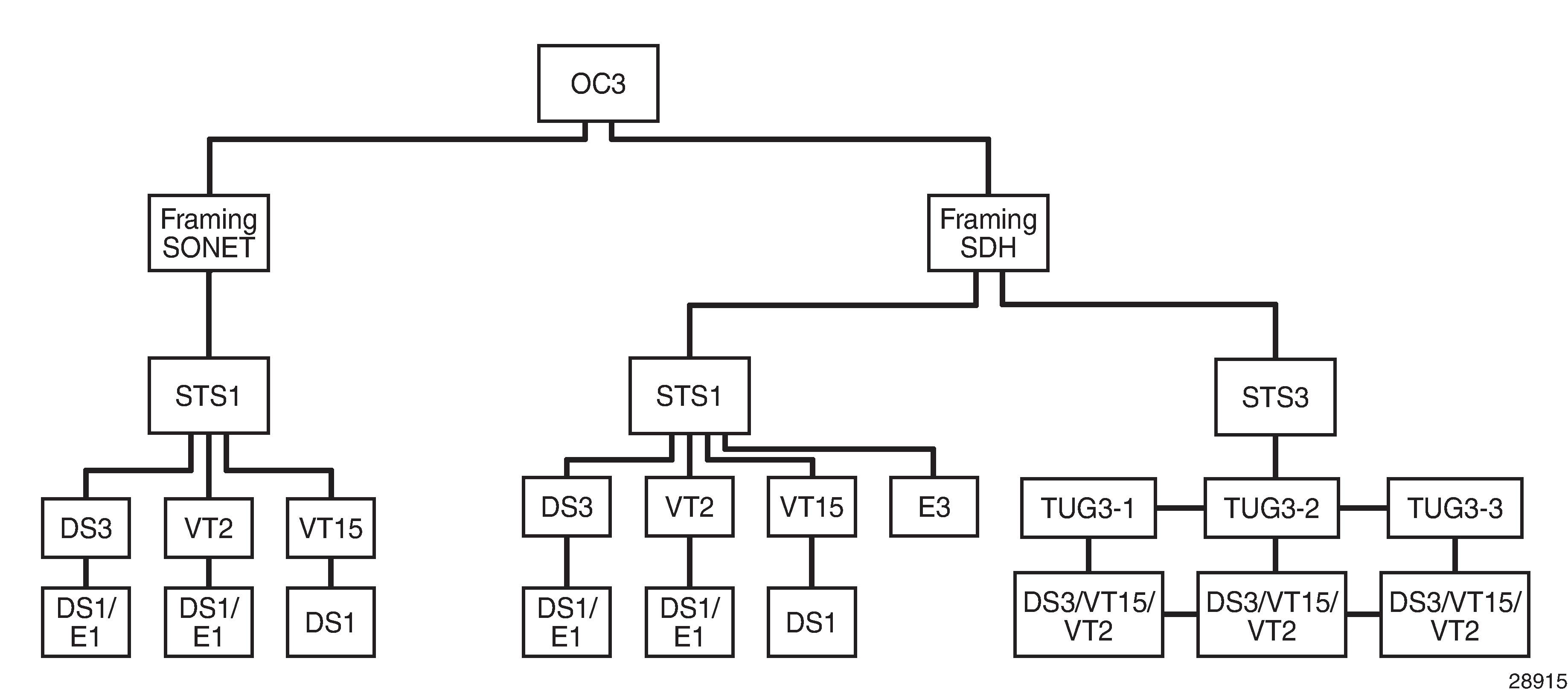
OC3 Channelization using SONET and SDH
In SONET, the base signal is referred to as synchronous transport signal–level 1 (STS-1), which operates at 51.84 Mb/s. Higher-level signals are integer multiples of STS-1, for example, STS-3/OC3 = 3 x STS-1 = 155.52 Mb/s. The SDH equivalent of the SONET STS-1 and STS-3 frames are STM-0 and STM-1, respectively.
In addition to the STS-1 base format, SONET also defines synchronous formats at sub-STS-1 levels. The STS-1 payload can be subdivided into virtual tributaries (VTs) for SONET or virtual containers (VCs) for SDH. VTs and VCs are synchronous signals used to transport lower-speed transmissions. Two VTs are VT1.5 and VT2, where:
VT1.5 = 1.728 Mb/s (enough to carry a T1)
VT2 = 2.304 Mb/s (enough to carry an E1)
The SDH equivalents to VT1.5 and VT2 are VC11 and VC12, respectively.
OC3 Channelization using SONET and SDH shows various possibilities for OC3 channelization using SONET and SDH framing. The VT1.5 and VT2 labels under the SDH STS1 path illustrate that SONET conventions are used for SDH configuration.
Configuring DS1/E1 on a Channelized OC3 Port with STS1 Path
This section provides several examples of configuring DS1/E1 channels and the use of the sonet-sdh-index parameter:
1. DS1 (SONET Framing, STS1)
There are three STS1 paths per OC3. The following examples use sts1-1.
There are two ways to configure a DS1 channel on a SONET framed port (see OC3 Channelization using SONET and SDH, SONET framing branch):
1.1 STS1 with channelized DS3 payload
To configure a DS1 on an STS1 with a channelized DS3 payload:
Create the STS1 path and set the payload to DS3.
Create the channelized DS3 on the STS1 path.
Create the DS1 on the DS3.
Use the info command to display configuration information.
         sonet-sdh
             path sts1-1
                 payload ds3
                 no shutdown
             exit
         exit
         tdm
             ds3 1
                 channelized ds1
                 no shutdown
             exit
             ds1 1.1
                 no shutdown
             exit
         exit
         no shutdown
Notes:
the CLI identifier for the path command is sts1-stsNum, where:
stsNum is the STS number, which can be 1, 2, or 3
the CLI identifier for the TDM ds3 command is ds3Num, where:
ds3Num is equal to stsNum
In the example above, DS3 is configured on sts1-1, hence the numbering ds3 1. If sts1-2 or sts1-3 was configured instead of sts1-1, the corresponding DS3 configuration would be ds3 2 or ds3 3, respectively.
the CLI identifier for the TDM ds1 command is ds3Num.ds1Num, where:
ds1Num is the DS1 number. Because a DS3 can carry 28 T1s, ds1Num can be between 1 and 28.
1.2 STS1 with VT1.5 payload
To configure a DS1 on an STS1 with a VT1.5 payload:
Create the STS1 path and set the payload to VT1.5.
Create the VT1.5 path on the STS1 path.
Create the DS1 on the VT1.5 path.
Use the info command to display configuration information. The example below creates two VT1.5 paths, each with its own DS1.
         sonet-sdh
             path sts1-1
                 payload vt15
                 no shutdown
             exit
             path vt15-1.1.1
                 payload ds1
                 no shutdown
             exit
             path vt15-1.7.4
                 payload ds1
                 no shutdown
             exit
         exit
         tdm
             ds1 1.1.1
                 no shutdown
             exit
             ds1 1.7.4
                 no shutdown
             exit
         exit
         no shutdown
Notes:
the CLI identifier for the VT1.5 path command is vt15-stsNum.vtGroupNum.vtNum, where:
vt15- is a keyword
stsNum is the STS1 number, which can be 1, 2, or 3
vtGroupNum is the VT group number. An STS1 frame contains seven VT groups, so vtGroupNum can be from 1 to 7
vtNum is the VT1.5 number. A VT group can hold four VT1.5 paths, so vtNum can be from 1 to 4
the CLI identifier for the TDM ds1 command is similar to the path command, namely, stsNum.vtGroupNum.ds1Num, where:
ds1Num is equal to vtNum
2. E1 (SONET Framing, STS1)
A DS3 can be configured to carry an E1 payload (see OC3 Channelization using SONET and SDH, SONET framing branch).
To configure an E1 on an STS1 with a DS3 payload:
Create the STS1 path and set the payload to DS3.
Create the TDM DS3 with channelized E1.
Create the TDM E1.
Use the info command to display configuration information. In the example below, which applies only to the 2-port OC3/STM1 Channelized Adapter card, DS3 1 carries two E1 channels.
         sonet-sdh
             path sts1-1
                 payload ds3
                 no shutdown
             exit
         exit
         tdm
             ds3 1
                 no shutdown
                 channelized e1
             exit
             e1 1.1
                 no shutdown
             exit
             e1 1.21
                 no shutdown
             exit
         exit
         no shutdown
Notes:
the CLI identifier for the path command is sts1-stsNum, where:
stsNum is between 1 and 3
the CLI identifier for the TDM ds3 command is ds3Num, where:
ds3Num is equal to stsNum
In the example above, DS3 is configured on sts1-1, hence the command ds3 1. If sts1-2 or sts1-3 was configured instead of sts1-1, the corresponding ds3 configuration would be ds3 2 or ds3 3, respectively.
the CLI identifier for the TDM e1 command is ds3Num.e1Num, where:
e1Num is between 1 and 21 because a DS3 can carry 21 E1s
Configuring DS1/E1 on a Channelized OC3 Port with STM Path
A SONET framed port—as well as an SDH framed port—can be divided into three STS1 paths. Each SONET port can be subdivided further into lower-speed virtual tributaries (VTs). Similarly, each SDH port can be subdivided into lower-speed virtual containers (VCs). As stated in OC3 Channelization using SONET and SDH, the CLI uses SONET STS1/VT configuration conventions to configure SDH VC paths.
The following examples illustrate the use of SONET CLI terminology to configure SDH paths. See the STS1 branch under SDH framing in OC3 Channelization using SONET and SDH.
1. DS1 (SDH Framing, STS1)
There are two ways to configure a DS1 channel on an SDH-framed port with STS1 paths:
1.1 STS1 with channelized DS3 payload
To configure a DS1 on an STS1 with a channelized DS3 payload:
Create the STS1 path and set the payload to DS3.
Create the TDM DS3 with channelized DS1.
Create the TDM DS1.
Use the info command to display configuration information.
         sonet-sdh
             framing sdh
             path sts1-1
                 payload ds3
                 no shutdown
             exit
         exit
         tdm
             ds3 1
                 channelized ds1
                 no shutdown
             exit
             ds1 1.1
                 no shutdown
             exit
         exit
         no shutdown
Notes:
the CLI identifier for the path command is sts1-stsNum:
where stsNum is between 1 and 3
the CLI identifier for the TDM ds3 command is ds3Num, where:
ds3Num is equal to stsNum
In the example above, DS3 is configured on sts1-1, hence the command ds3 1. If sts1-2 or sts1-3 was configured instead of sts1-1, the corresponding ds3 configuration would be ds3 2 or ds3 3, respectively.
the CLI identifier for the TDM ds1 command is ds3Num.ds1Num, where:
ds1Num is between 1 and 28 because a DS3 can carry 28 T1s
1.2 STS1 with VT1.5 payload
To configure a DS1 on an STS1 with a VT1.5 payload:
Create the STS1 path and set the payload to VT1.5.
Create the VT1.5 path and set the payload to DS1.
Create the corresponding TDM DS1.
There is one DS1 per VT1.5 path.
Use the info command to display configuration information. This example creates two VT1.5 payloads, each having a corresponding DS1 channel.
         sonet-sdh
             framing sdh
             path sts1-1
                 payload vt15
                 no shutdown
             exit
             path vt15-1.1.1
                 payload ds1
                 no shutdown
             exit
             path vt15-1.7.4
                 payload ds1
                 no shutdown
             exit
         exit
         tdm
             ds1 1.1.1
                 no shutdown
             exit
             ds1 1.7.4
                 no shutdown
             exit
         exit
         no shutdown
Notes:
the CLI identifier for the VT1.5 path command is vt15-stsNum.vtGroupNum.vtNum
vt15- is a keyword
stsNum is the STS1 number, which can be 1, 2, or 3
vtGroupNum is the VT group number. An STS1 frame contains seven VT groups, so vtGroupNum can be from 1 to 7
vtNum is the VT1.5 number. A VT group can hold four VT1.5 paths, so vtNum can be from 1 to 4
the CLI identifier for the TDM ds1 command is similar to the path command, namely, stsNum.vtGroupNum.ds1Num, where:
ds1Num is equal to vtNum
2. E1 (SDH Framing, STS1)
There are two ways to configure an E1 channel on an SDH-framed port with STS1 paths (see the STS1 branch under SDH framing in OC3 Channelization using SONET and SDH):
2.1 STS1 with channelized DS3 payload
To configure an E1 on an STS1 with a DS3 payload:
Create the STS1 path with SDH framing and set the payload to DS3.
Create a TDM DS3 with a channelized E1.
Create the corresponding E1.
Use the info command to display configuration information. In the example below, DS3 1 carries two E1 channels.
         sonet-sdh
             framing sdh
             path sts1-1
                 payload ds3
                 no shutdown
             exit
         exit
         tdm
             ds3 1
                 no shutdown
                 channelized e1
             exit
             e1 1.1
                 no shutdown
             exit
             e1 1.21
                 no shutdown
             exit
         exit
         no shutdown
Notes:
the CLI identifier for the path command is sts1-stsNum, where:
stsNum is between 1 and 3
the CLI identifier for the TDM ds3 command is ds3Num, where:
ds3Num is equal to stsNum
In the example above, DS3 is configured on sts1-1, hence the command ds3 1. If sts1-2 or sts1-3 was configured instead of sts1-1, the corresponding ds3 configuration would be ds3 2 or ds3 3, respectively.
the CLI identifier for the TDM e1 command is ds3Num.e1Num, where:
e1Num is between 1 and 21 because a DS3 can carry 21 E1s
2.2 STS1 with VT2 payload
To configure an E1 on an STS1 with a VT2 payload:
Create the STS1 path and set the payload to VT2.
Create the VT2 path and set the payload to E1.
Create the corresponding TDM E1.
Use the info command to display configuration information.
         sonet-sdh
             framing sdh
             path sts1-1
                 no shutdown
                 payload vt2
             exit
             path vt2-1.6.3
                 payload e1
                 no shutdown
             exit
         exit
         tdm
             e1 1.6.3
                 no shutdown
             exit
         exit
         no shutdown
Notes:
the CLI identifier for the VT2 path command is vt2-stsNum.vtGroupNum.vtNum, where:
vt2- is a keyword
stsNum is the STS1 number, which can be 1, 2, or 3
vtGroupNum is the VT group number. An STS1 frame contains seven VT groups, so vtGroupNum can be from 1 to 7
vtNum is the VT2 number. A VT group can hold three VT2 paths, so vtNum can be from 1 to 3
the CLI identifier for the TDM e1 command is similar to the path command, namely, stsNum.vtGroupNum.e1Num, where:
e1Num is equal to vtNum
Configuring DS1/E1 on a Channelized OC3 Port with STS3 Path
Unique to an SDH framed port is the ability to configure a single STS3 path instead of three STS1 paths. When as STS3 path is configured, the VTs are configured using tributary units (TUs). One or more TUs can be combined into a tributary unit group (TUG) (see the STS3 branch in OC3 Channelization using SONET and SDH).
When an STS3 path is configured on an SDH port, the three TUGs in the following configuration are created by default. Each TUG can be considered the equivalent of an STS1 path.
   port 1/1/1
     sonet-sdh
       framing sdh
         path sts3
       exit
     group tug3-1 payload tu3
     group tug3-2 payload tu3
     group tug3-3 payload tu3
This section provides information on the following topics:
1. DS1 (SDH Framing, STS3)
There are two ways to configure a DS1 on an SDH framed port with an STS3 path:
1.1 STS3 / TUG with VT1.5 payload
To configure a DS1 on an STS3 / TUG with a VT1.5 payload:
Configure an STS3 path on the port.
Configure one of the three TUGs for a VT1.5 payload.
Create a VT1.5 path with a DS1 payload on the STS3 path / TUG.
Create a DS1 on the VT1.5 path.
Use the info command to display configuration information.
         sonet-sdh
             framing sdh
             path sts3
                 no shutdown
             exit
             group tug3-1 payload vt15
             path vt15-1.2.3
                 payload ds1
                 no shutdown
             exit
         exit
         tdm
             ds1 1.2.3
                 no shutdown
             exit
Notes:
the CLI identifier for the VT1.5 path is vt15-tugNum.vtGroupNum.vtNum, where:
vt15- is a keyword
tugNum is the TUG number, which can be 1, 2, or 3
vtGroupNum is the VT group number. A TUG3 contains seven VT groups, so vtGroupNum can be from 1 to 7
vtNum is the VT1.5 number. A VT group can hold four VT1.5 paths, so vtNum can be from 1 to 4
the CLI identifier for the TDM ds1 command is similar to that of the path command, namely, tugNum.vtGroupNum.ds1Num, where:
ds1Num is equal to vtNum
1.2 STS3 / TUG with TU3 payload
To configure a DS1 on an STS3 / TUG with a TU3 payload:
Configure an STS3 path on the port.
Create a TU3 path with the default payload.
Create the TDM DS3 with channelized DS1.
Create the TDM DS1.
Use the info command to display configuration information.
         sonet-sdh
             framing sdh
             path sts3
                 no shutdown
             exit
             path tu3-1
                no shutdown
            exit
        exit
        tdm
            ds3 1
                channelized ds1
                no shutdown
            exit
            ds1 1.1
                no shutdown
            exit
        exit
Notes:
The CLI identifier for the TDM ds1 command is similar to that of the path command, namely, tugNum.vtGroupNum.ds1Num, where:
ds1Num is equal to vtNum
2. E1 (SDH Framing, STS3)
To configure an E1 on an SDH framed port with an STS3 path:
Configure an STS3 path on the port.
Configure one of the three TUGs for a VT2 payload.
Create a VT2 path with an E1 payload on the STS3 path / TUG.
Create an E1 on the VT2 path.
Use the info command to display configuration information.
         sonet-sdh
             framing sdh
             path sts3
                 no shutdown
             exit
             group tug3-1 payload vt2
             path vt2-1.2.3
                 payload e1
                 no shutdown
             exit
         exit
         tdm
             e1 1.2.3
                 no shutdown
             exit
         exit
Notes:
the CLI identifier for the VT2 path command is vt2-tugNum.vtGroupNum.vtNum, where:
tugNum is the TUG number, which can be 1, 2, or 3
vtGroupNum is the VT group number. A TUG3 contains seven VT groups, so vtGroupNum can be from 1 to 7
vtNum is the VT2 number. A VT group can hold three VT2 paths, so vtNum can be from 1 to 3
the CLI identifier for the TDM e1 command is similar to the path command, namely, tugNum.vtGroupNum.e1Num, where:
e1Num is equal to vtNum
Configuring a SONET/SDH Port with Multiple DS1s in an MLPPP Bundle
Configuring SONET/SDH Network Port illustrates the setup to configure port 1/2/2 on 7705 SAR_118 as a SONET/SDH port with three DS1s on a channelized OC3/STM1 adapter card using SDH or SONET framing, and to configure the three DS1s for use in an MLPPP bundle on the network side.
This section provides information about the following topics:
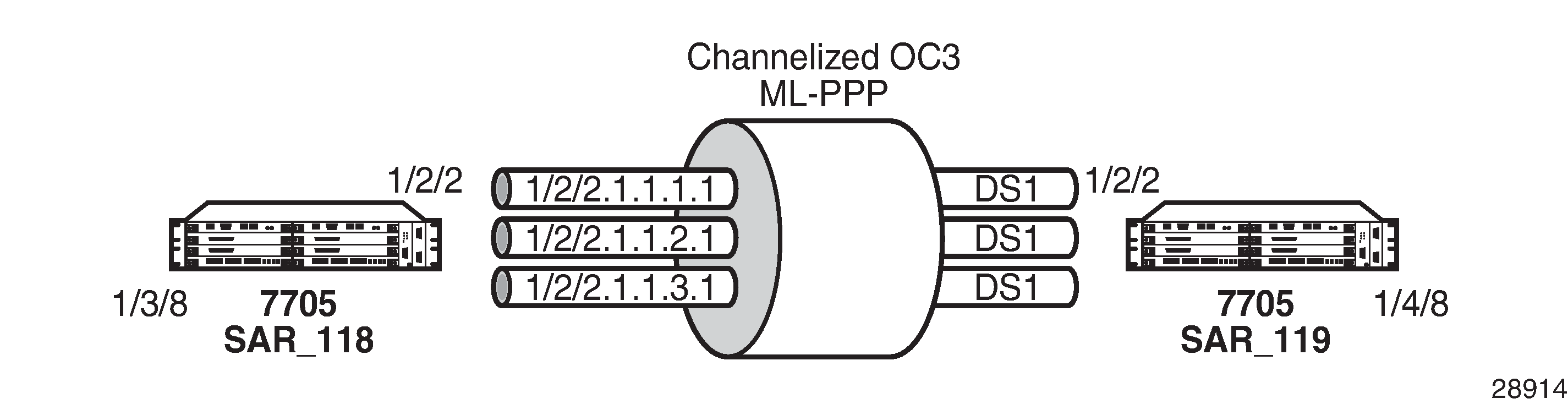
Configuring the Network Port
Configure the DS1s.
The following CLI syntax shows an example of configuring three DS1s on a channelized OC3/STM1 adapter card using SDH framing. The framing must match on both ends.
If SONET framing is needed, use the CLI syntax after this SDH syntax.
- CLI Syntax:
configure port 1/2/2config>port# description "to-SAR119"config>port# sonet-sdhconfig>port>sonet-sdh# framing sdhconfig>port>sonet-sdh# path sts3 no shutdownconfig>port>sonet-sdh# group tug3-1 payload vt15config>port>sonet-sdh# path vt15-1.1.1config>port>sonet-sdh>path# no shutdownconfig>port>sonet-sdh>path# exitconfig>port>sonet-sdh# path vt15-1.1.2config>port>sonet-sdh>path# no shutdownconfig>port>sonet-sdh>path# exitconfig>port>sonet-sdh# path vt15-1.1.3config>port>sonet-sdh>path# no shutdownconfig>port>sonet-sdh>path# exitconfig>port>sonet-sdh# exitconfig>port# tdmconfig>port>tdm# ds1 1.1.1config>port>tdm>ds1# channel-group 1config>port>tdm>ds1>channel-group# mode networkconfig>port>tdm>ds1>channel-group# encap-type ppp-autoconfig>port>tdm>ds1>channel-group# no shutdownconfig>port>tdm>ds1>channel-group# exitconfig>port>tdm>ds1# no shutdownconfig>port>tdm>ds1# exitconfig>port>tdm# ds1 1.1.2config>port>tdm>ds1# channel-group 1config>port>tdm>ds1>channel-group# mode networkconfig>port>tdm>ds1>channel-group# encap-type ppp-autoconfig>port>tdm>ds1>channel-group# no shutdownconfig>port>tdm>ds1>channel-group# exitconfig>port>tdm>ds1# no shutdownconfig>port>tdm>ds1# exitconfig>port>tdm# ds1 1.1.3config>port>tdm>ds1# channel-group 1config>port>tdm>ds1>channel-group# mode networkconfig>port>tdm>ds1>channel-group# encap-type ppp-autoconfig>port>tdm>ds1>channel-group# no shutdownconfig>port>tdm>ds1>channel-group# exitconfig>port>tdm>ds1# no shutdownconfig>port>tdm>ds1# exitconfig>port>tdm# exitconfig>port# exit*A:SAR118#
The following CLI syntax shows the configuration of the same example using SONET framing. The framing must match on both ends.
- CLI Syntax:
configure port 1/2/2config>port# description "to-SAR119"config>port# sonet-sdhconfig>port>sonet-sdh# framing sonetconfig>port>sonet-sdh# path sts1-1config>port>sonet-sdh>path# payload vt15config>port>sonet-sdh>path# exitconfig>port>sonet-sdh# path vt15-1.1.1config>port>sonet-sdh>path# no shutdownconfig>port>sonet-sdh>path# exitconfig>port>sonet-sdh# path vt15-1.1.2config>port>sonet-sdh>path# no shutdownconfig>port>sonet-sdh>path# exitconfig>port>sonet-sdh# path vt15-1.1.3config>port>sonet-sdh>path# no shutdownconfig>port>sonet-sdh>path# exitconfig>port>sonet-sdh# exitconfig>port# tdmconfig>port>tdm# ds1 1.1.1config>port>tdm>ds1# channel-group 1config>port>tdm>ds1>channel-group# mode networkconfig>port>tdm>ds1>channel-group# encap-type ppp-autoconfig>port>tdm>ds1>channel-group# no shutdownconfig>port>tdm>ds1>channel-group# exitconfig>port>tdm>ds1# no shutdownconfig>port>tdm>ds1# exitconfig>port>tdm# ds1 1.1.2config>port>tdm>ds1# channel-group 1config>port>tdm>ds1>channel-group# mode networkconfig>port>tdm>ds1>channel-group# encap-type ppp-autoconfig>port>tdm>ds1>channel-group# no shutdownconfig>port>tdm>ds1>channel-group# exitconfig>port>tdm>ds1# no shutdownconfig>port>tdm>ds1# exitconfig>port>tdm# ds1 1.1.3config>port>tdm>ds1# channel-group 1config>port>tdm>ds1>channel-group# mode networkconfig>port>tdm>ds1>channel-group# encap-type ppp-autoconfig>port>tdm>ds1>channel-group# no shutdownconfig>port>tdm>ds1>channel-group# exitconfig>port>tdm>ds1# no shutdownconfig>port>tdm>ds1# exitconfig>port>tdm# exitconfig>port# exit
Create an MLPPP bundle using the three DS1s.
- CLI Syntax:
configure port bundle-ppp-1/2.1config>port# multilink-bundleconfig>port>ml-bundle# member 1/2/2.1.1.1.1config>port>ml-bundle# member 1/2/2.1.1.2.1config>port>ml-bundle# member 1/2/2.1.1.3.1config>port>ml-bundle# exitconfig>port# no shutdownconfig>port# exit
Repeat the same configurations on 7705 SAR_119 port 1/2/2.
Verifying the Configured Network Ports
*A:SAR118# show port 1/2
==============================================================================
Ports on Slot 1
==============================================================================
Port        Admin Link Port    Cfg  Oper LAG/ Port Port Port   SFP/XFP/
Id          State      State   MTU  MTU  Bndl Mode Encp Type   MDIMDX
------------------------------------------------------------------------------
1/2/1       Down  No   Down
1/2/2       Up    Yes  Link Up                                 OC3-SR-MM
1/2/2.1.1.1.1
            Up    Yes  Up      1572 1572    1 netw pppa tdm
1/2/2.1.1.2.1
            Up    Yes  Up      1572 1572    1 netw pppa tdm
1/2/2.1.1.3.1
            Up    Yes  Up      1572 1572    1 netw pppa tdm
==============================================================================
*A:SAR118#
Verifying the Available Channelization
Use the port-tree command to confirm the current channelization of the OC3 channel.
Until port 1/2/1 is configured, the default STS3 is subdivided into three STS1s, each having a payload type of DS3.
*A:SAR119# show port-tree 1/2/1
    ifIndex  type, sonet-sdh-index (* = provisioned)
===========  =======================================
   37781504  Port, N/A *
  574652417      STS3, none
  574652478          STS1, sts1-1
  574652481              DS3, 1
  574652484          STS1, sts1-2
  574652487              DS3, 2
  574652488          STS1, sts1-3
  574653222              DS3, 3
When port 1/2/1 path sts1-1 has been provisioned (indicated in the following output by an ‟*” in line 574652478), all the available VT1.5 paths under sts1-1 on port 1/2/1 are created and listed. In this case, all seven VT groups (VTGs) are listed, each containing four VT1.5 paths. The remaining two STS1s (sts1-2 and sts1-3) still have DS3 payloads.
The following configure command provisions sts1-1 with VT1.5 paths, which appear in the port-tree command that follows.
*A:SAR119# configure port 1/2/1 sonet-sdh path sts1-1 payload vt15

*A:SAR119# show port-tree 1/2/1
    ifIndex  type, sonet-sdh-index (* = provisioned)
===========  =======================================
   37781504  Port, N/A *
  574652417      STS3, none
  574652478          STS1, sts1-1 *
  N/A                    VTG, 1.1
  574653223                  VT15, vt15-1.1.1
  574653224                      DS1, 1.1.1
  574653249                  VT15, vt15-1.1.2
  574653250                      DS1, 1.1.2
  574653275                  VT15, vt15-1.1.3
  574653276                      DS1, 1.1.3
  574653301                  VT15, vt15-1.1.4
  574653302                      DS1, 1.1.4
  N/A                    VTG, 1.2
  574653328                  VT15, vt15-1.2.1
  574653329                      DS1, 1.2.1
  574653354                  VT15, vt15-1.2.2
  574653355                      DS1, 1.2.2
  574653380                  VT15, vt15-1.2.3
  574653381                      DS1, 1.2.3
  574653406                  VT15, vt15-1.2.4
  574653407                      DS1, 1.2.4
  N/A                    VTG, 1.3
  574653433                  VT15, vt15-1.3.1
  574653434                      DS1, 1.3.1
  574653459                  VT15, vt15-1.3.2
  574653460                      DS1, 1.3.2
  574653485                  VT15, vt15-1.3.3
  574653486                      DS1, 1.3.3
  574653511                  VT15, vt15-1.3.4
  574653512                      DS1, 1.3.4
  N/A                    VTG, 1.4
  574653538                  VT15, vt15-1.4.1
  574653539                      DS1, 1.4.1
  574653564                  VT15, vt15-1.4.2
  574653565                      DS1, 1.4.2
  574653590                  VT15, vt15-1.4.3
  574653591                      DS1, 1.4.3
  574653616                  VT15, vt15-1.4.4
  574653617                      DS1, 1.4.4
  N/A                    VTG, 1.5
  574653643                  VT15, vt15-1.5.1
  574653644                      DS1, 1.5.1
  574653669                  VT15, vt15-1.5.2
  574653670                      DS1, 1.5.2
  574653695                  VT15, vt15-1.5.3
  574653696                      DS1, 1.5.3
  574653721                  VT15, vt15-1.5.4
  574653722                      DS1, 1.5.4
  N/A                    VTG, 1.6
  574653748                  VT15, vt15-1.6.1
  574653749                      DS1, 1.6.1
  574653774                  VT15, vt15-1.6.2
  574653775                      DS1, 1.6.2
  574653800                  VT15, vt15-1.6.3
  574653801                      DS1, 1.6.3
  574653826                  VT15, vt15-1.6.4
  574653827                      DS1, 1.6.4
  N/A                    VTG, 1.7
  574653853                  VT15, vt15-1.7.1
  574653854                      DS1, 1.7.1
  574653879                  VT15, vt15-1.7.2
  574653880                      DS1, 1.7.2
  574653905                  VT15, vt15-1.7.3
  574653906                      DS1, 1.7.3
  574653931                  VT15, vt15-1.7.4
  574653932                      DS1, 1.7.4
  574652484          STS1, sts1-2
  574652487              DS3, 2
  574652488          STS1, sts1-3
  574653222              DS3, 3
*A:SAR119#
Configuring Voice Ports
Use the following CLI syntax to configure an analog voice port on a 6-port E&M Adapter card.
- CLI Syntax:
port port-idvoiceaudio-wires {four-wires | two-wires}[no] em[no] channel-group channel-group-id[no] description description-string[no] encap-type cemmode access[no] shutdownfault-signaling {idle | seized}[no] idle-code abcd-code[no] seized-code abcd-code[no] loopback {internal-analog | internal-digital}signaling-leade {high | low | end-to-end}m {high | low | end-to-end}signaling-mode {em | transmission-only}[no] shutdowntlp-rx {-16.0 | -15.9 | ... | 6.9 | 7.0}tlp-tx {-16.0 | -15.9 | ... | 6.9 | 7.0}
The following CLI syntax shows an example of configuring an analog voice port on a 6-port E&M Adapter card. The default values are used for the commands that are not shown in the example.
- Example:
config# port 1/1/1config>port# voiceconfig>port>voice# emconfig>port>voice# em# channel-group 1config>port>voice# em# channel-group# mode accessconfig>port>voice# em# channel-group# encap-type cemconfig>port>voice# em# channel-group# no shutdownconfig>port>voice# em# channel-group# exitconfig>port>voice# em# signaling-leadconfig>port>voice# em# signaling-lead# e highconfig>port>voice# em# signaling-lead# exitconfig>port>voice# em# signaling-modeconfig>port>voice# em# signaling-mode# emconfig>port>voice# em# signaling-mode# exitconfig>port>voice# em# no shutdownconfig>port>voice# em# exitconfig>port>voice# exitconfig>port# no shutdownconfig>port# exitconfig#
Use the following CLI syntax to configure an analog voice port on an 8-port Voice & Teleprotection card.
- CLI Syntax:
port port-idvoicefxochannel-group channel-group-iddescription description-stringencap-type {cem}mode accessno shutdownfault-signaling {idle | seized}loopback {internal-digital}no shutdownfxschannel-group channel-group-iddescription description-stringencap-type cemmode accessno shutdownfault-signaling {idle | seized}loopback {internal-digital}ring-generation {16 | 20 | 25}no shutdownline-balance {nominal | 800 | short | long}signaling-type {3600plar | 1511plar | 3600ls | 1511profile1 | 3600re | 1511sn137}tlp-rx decibels {-7.0 | -6.9 | ... | -0.1 | 0.0}tlp-tx decibels {-4.0 | -3.9 | ... | 2.9 | 3.0}
The following CLI syntax shows an example of configuring an analog voice port on an 8-port Voice & Teleprotection card. The default values are used for the commands that are not shown in the example.
- Example:
config# port 1/1/6config>port# voiceconfig>port>voice# fxoconfig>port>voice>fxo# channel-group 1config>port>voice>fxo>channel-group# mode accessconfig>port>voice>fxo>channel-group# encap-type cemconfig>port>voice>fxo>channel-group# no shutdownconfig>port>voice>fxo>channel-group# exitconfig>port>voice>fxo# no shutdownconfig>port>voice>fxo# exitconfig>port>voice# exitconfig>port# no shutdownconfig>port# exitconfig#
Use the following CLI syntax to configure an analog voice port on an 8-port FXO Adapter card.
- CLI Syntax:
port port-idvoicefxochannel-group channel-group-iddescription description-stringencap-type cemmode accessno shutdownfault-signaling {idle | seized}loopback internal-digitalno shutdownline-balance {nominal | 800}signaling-type {3600ls | 1511profile1 | 3600re | 1511sn137}tlp-rx decibels {-7.0 | -6.9 | ... | -0.1 | 0.0}tlp-tx decibels {-4.0 | -3.9 | ... | 2.9 | 3.0}
The following CLI syntax shows an example of configuring an analog voice port on an 8-port FXO Adapter card. The default values are used for the commands that are not shown in the example.
- Example:
config# port 1/1/6config>port# voiceconfig>port>voice# fxoconfig>port>voice>fxo# channel-group 1config>port>voice>fxo>channel-group# mode accessconfig>port>voice>fxo>channel-group# encap-type cemconfig>port>voice>fxo>channel-group# no shutdownconfig>port>voice>fxo>channel-group# exitconfig>port>voice>fxo# no shutdownconfig>port>voice>fxo# exitconfig>port>voice# exitconfig>port# no shutdownconfig>port# exitconfig#
Use the following CLI syntax to configure an analog voice port on a 6-port FXS Adapter card.
- CLI Syntax:
port port-idvoicefxschannel-group channel-group-iddescription description-stringencap-type cemmode accessno shutdownfault-signaling {idle | seized}loopback internal-digitalno shutdownline-balance {nominal | 800}ring-generation {16 | 20 | 25}signaling-type {3600plar | 1511plar |3600ls |1511profile1 | 3600re | 1511sn137}tlp-rx {-7.0 | -6.9 | ... | -0.1 | 0.0}tlp-tx {-4.0 | -3.9 | ... | 2.9 | 3.0}
The following CLI syntax shows an example of configuring an analog voice port on a 6-port FXS Adapter card.
- Example:
config# port 1/6/1config>port# voiceconfig>port>voice# fxsconfig>port>voice>fxs# channel-group 1config>port>voice>fxs>channel-group# mode accessconfig>port>voice>fxs>channel-group# encap-type cemconfig>port>voice>fxs>channel-group# no shutdownconfig>port>voice>fxs>channel-group# exitconfig>port>voice>fxs# no shutdownconfig>port>voice>fxs# exitconfig>port>voice# line-balance nominalconfig>port>voice# ring-generation 16config>port>voice# signaling-type 3600lsconfig>port>voice# tlp-rx -7.0config>port>voice# tlp-tx -4.0config>port>voice# exitconfig>port# exit
Configuring Codirectional G.703 Ports
Use the following CLI syntax to configure a codirectional G.703 port on an 8-port Voice & Teleprotection card.
- CLI Syntax:
port port-idtdmcodirchannel-group channel-group-iddescription description-stringencap-type cemmode accessno shutdownloopback {internal | line}report-alarm {ais | los}no shutdown
The following CLI syntax shows an example of configuring a codirectional G.703 port on an 8-port Voice & Teleprotection card.
- Example:
config# port 1/1/2config>port# tdmconfig>port>tdm>codirconfig>port>tdm>codir# channel-group 1config>port>tdm>codir>channel-group# description ‟CG 1”config>port>tdm>codir>channel-group# encap-type cemconfig>port>tdm>codir>channel-group# mode accessconfig>port>tdm>codir>channel-group# no shutdownconfig>port>tdm>codir>channel-group# exitconfig>port>tdm>codir# loopback lineconfig>port>tdm>codir# report-alarm aisconfig>port>tdm>codir# no shutdownconfig>port>tdm>codir# exitconfig>port>tdm# exit
Configuring Teleprotection Ports
Use the following CLI syntax to configure a teleprotection port on an 8-port Voice & Teleprotection card or 8-port C37.94 Teleprotection card.
- CLI Syntax:
port port-idtdmtpifchannel-group channel-group-iddescription description-stringencap-type cemmode accessno shutdowntimeslots timeslotsframing {framed | unframed}loopback {internal | line}report-alarm {los | rai}no shutdown
The following CLI syntax shows an example of configuring a teleprotection port on an 8-port Voice & Teleprotection card or an 8-port C37.94 Teleprotection card.
- Example:
config# port 1/1/3config>port# tdmconfig>port>tdm>tpifconfig>port>tdm>tpif# channel-group 1config>port>tdm>tpif>channel-group# description ‟TPIF 1”config>port>tdm>tpif>channel-group# encap-type cemconfig>port>tdm>tpif>channel-group# mode accessconfig>port>tdm>tpif>channel-group# timeslots 1config>port>tdm>tpif>channel-group# no shutdownconfig>port>tdm>tpif>channel-group# exitconfig>port>tdm>tpif# framing framedconfig>port>tdm>tpif# loopback internalconfig>port>tdm>tpif# report-alarm losconfig>port>tdm>tpif# no shutdownconfig>port>tdm>tpif# exitconfig>port>tdm# exit
Configuring TDM PPP
Use the following CLI syntax to configure PPP parameters for TDM DS3/E3 ports or DS3 channels.
- CLI Syntax:
port port-idtdmds3encap-type ppp-automode networkpppkeepalive time-interval [dropcount drop-count]no keepalivee3encap-type ppp-automode networkpppkeepalive time-interval [dropcount drop-count]no keepalive
Configuring Channelized Ports
Channelized ports are supported on the following cards and modules:
16-port T1/E1 ASAP Adapter card
32-port T1/E1 ASAP Adapter card
12-port Serial Data Interface card
6-port E&M Adapter card
2-port OC3/STM1 Channelized Adapter card
4-port OC3/STM1 / 1-port OC12/STM4 Adapter card
4-port DS3/E3 Adapter card
8-port Voice & Teleprotection card
8-port C37.94 Teleprotection card
4-port T1/E1 and RS-232 Combination module
8-port FXO Adapter card
6-port FXS Adapter card
When configuring channelized ports, the port ID is specified in different ways depending on the TDM type and level of channelization, as follows:
N ✕ DS0 in DS1 port.channel-group, where channel-group is 1 to 24
N ✕ DS0 in E1 port.channel-group, where channel-group is 1 to 32
N ✕ DS1 in DS3 port.DS1 port.channel-group, where channel-group is 1 to 24
N ✕ E1 in E3 port.E1 port.channel-group, where channel-group is 1 to 32
1 ✕ DS0 in V.35, RS-232, or X.21 port.channel-group, wherechannel-group is 1
1 ✕ DS0 in E&M, FXO, or FXS port.channel-group, wherechannel-group is 1
1 ✕ DS0 in codirectional port.channel-group, where channel-group is 1
N ✕ DS0 in TPIF port.channel-group, where channel-group is 1
Verifying the Adapter Card Type
To ensure that you have a channel-capable adapter card, verify the adapter card you are configuring by using the show mda command.
In the following example, mda 1, mda 3, mda 4, and mda 6 show channelized adapter cards on the 7705 SAR-8 Shelf V2.
*A:NOK-1# show mda
===============================================================================
MDA Summary
===============================================================================
Slot  Mda   Provisioned Type                            Admin     Operational
                Equipped Type (if different)            State     State
-------------------------------------------------------------------------------
1     1     a12-sdiv2                                   up        up
      2     a4-oc3                                      up        up
      3     a16-chds1v2                                 up        up
      4     a4-chds3v2                                  up        up
      5     a8-1gb-sfp                                  up        up
      6     a2-choc3                                    up        up
===============================================================================
*A:NOK-1
Use the show mda detail command to show detailed information for the channelized adapter cards shown in the previous example.
*A:NOK-1# show mda 1/1 detail
===============================================================================
MDA 1/1 detail
===============================================================================
Slot  Mda   Provisioned Type                            Admin     Operational
                Equipped Type (if different)            State     State
-------------------------------------------------------------------------------
1     1     a12-sdiv2                                   up        provisioned

MDA Specific Data
    Maximum port count            : 12
    Number of ports equipped      : 12
    Network ingress queue policy  : default
    Network ingress fabric policy : 1
    Access ingress fabric policy  : 1
    Fabric Stats Enabled          : TRUE
    Capabilities                  : Serial, CEM
    Min channel size              : PDH DS0 Group
    Max channel size              : Serial RS-232
    Max number of channels        : 12
    Channels in use               : 2

CEM MDA Specific Data
    Clock Mode                    : n/a

Hardware Data
    Part number                   :
    CLEI code                     :
    Serial number                 :
    Manufacture date              :
    Manufacturing string          :
    Manufacturing deviations      :
    Administrative state          : up
    Operational state             : provisioned
    Software version              : N/A
    Time of last boot             : N/A
    Current alarm state           : alarm cleared
    Base MAC address              :
===============================================================================
*A:NOK-1#


*A:NOK-1# show mda 1/3 detail
===============================================================================
MDA 1/3 detail
===============================================================================
Slot  Mda   Provisioned Type                            Admin     Operational
                Equipped Type (if different)            State     State
-------------------------------------------------------------------------------
1     3     a16-chds1v2                                 up        up

MDA Specific Data
    Maximum port count            : 16
    Number of ports equipped      : 16
    Network ingress queue policy  : default
    Network ingress fabric policy : 1
    Access ingress fabric policy  : 1
    Fabric Stats Enabled          : FALSE
    Capabilities                  : TDM, PPP, ATM, CEM
    Min channel size              : PDH DS0 Group
    Max channel size              : PDH DS1
    Max number of channels        : 256
    Channels in use               : 3

CEM MDA Specific Data
    Clock Mode                    : adaptive

Hardware Data
    Part number                   : Sim Part#
    CLEI code                     : Sim CLEI
    Serial number                 : mda-3
    Manufacture date              : 01012003
    Manufacturing string          : Sim MfgString mda-3
    Manufacturing deviations      : Sim MfgDeviation mda-3
    Administrative state          : up
    Operational state             : up
    Software version              : N/A
    Time of last boot             : N/A
    Current alarm state           : alarm active
    Base MAC address              : a4:58:01:03:00:01
===============================================================================
*A:NOK-1#

*A:NOK-1# show mda 1/5 detail
===============================================================================
MDA 1/5 detail
===============================================================================
Slot  Mda   Provisioned Type                            Admin     Operational
                Equipped Type (if different)            State     State
-------------------------------------------------------------------------------
1     5     a2-choc3                                    up        up

MDA Specific Data
    Maximum port count            : 2
    Number of ports equipped      : 2
    Network ingress queue policy  : default
    Network ingress fabric policy : 1
    Access ingress fabric policy  : 1
    Fabric Stats Enabled          : FALSE
    Capabilities                  : Sonet, TDM, PPP, ATM
    Min channel size              : PDH DS0 Group
    Max channel size              : PDH DS3
    Max number of channels        : 512
    Channels in use               : 0

Hardware Data
    Part number                   : 3HE03127AAAB0102
    CLEI code                     : IPU3AFPEAA
    Serial number                 : NS092040281
    Manufacture date              : 05192009
    Manufacturing string          : ECO C03759
    Manufacturing deviations      :
    Administrative state          : up
    Operational state             : up
    Temperature                   : 37C
    Temperature threshold         : 75C
    Software version              : N/A
    Time of last boot             : 2009/06/28 18:47:04
    Current alarm state           : alarm cleared
    Base MAC address              : a4:58:01:03:00:01
===============================================================================
*A:NOK-1#
On the 16-port T1/E1 ASAP Adapter card, 32-port T1/E1 ASAP Adapter card, 2-port OC3/STM1 Channelized Adapter card, 4-port DS3/E3 Adapter card, and T1/E1 ports on the 4-port T1/E1 and RS-232 Combination module, DS0 channel groups and their parameters are configured in the DS1 or E1 context. For a DS1 channel group, up to 24 timeslots can be assigned (numbered 1 to 24). For an E1 channel group, up to 31 timeslots can be assigned (numbered 2 to 32). For ATM, all timeslots are auto-configured when a channel group gets created. The 4-port OC3/STM1 / 1-port OC12/STM4 Adapter card supports channelization at the DS1/E1 level only.
On the 6-port E&M Adapter card, a single DS0 channel group and its parameters are configured in the E&M context.
On the 12-port Serial Data Interface card and RS-232 ports of the 4-port T1/E1 and RS-232 Combination module, DS0 channel groups and their parameters are configured in the V.35, RS-232, RS-530, or X.21 context. For RS-232, a single timeslot is auto-configured when a channel group is created. For V.35 and X.21, the number of timeslots auto-configured when a channel group is created depends on the interface speed.
On the 8-port Voice & Teleprotection card, a single DS0 channel group and its parameters are configured in the codirectional, FXO, FXS, or TPIF context and up to 12 timeslots can be assigned in the TPIF context.
On the 8-port C37.94 Teleprotection card, a single DS0 channel group and its parameters are configured in the TPIF context and up to 12 timeslots can be assigned in the TPIF context.
Encapsulation type is configured at the DS1 or E1 level on the following:
16-port T1/E1 ASAP Adapter card
32-port T1/E1 ASAP Adapter card
2-port OC3/STM1 Channelized Adapter card
4-port OC3/STM1 / 1-port OC12/STM4 Adapter card
4-port DS3/E3 Adapter card
T1/E1 ports of the 4-port T1/E1 and RS-232 Combination module
The encapsulation type is configured at the RS-232, RS-530, V.35, or X.21 level for the following:
12-port Serial Data Interface card
RS-232 ports of the 4-port T1/E1 and RS-232 Combination module
A port can support only one encapsulation type. When the first channel group is configured for an encapsulation type, all other channel groups on the port are automatically configured with that encapsulation type. To change an encapsulation type, the channel group must be deleted, then recreated with the new encapsulation type.
The following is an example of an E1 channel group configuration.
NOK-A>config>port>tdm# e1
NOK-A>config>port>tdm>e1# channel-group 1
NOK-A>config>port>tdm>e1>channel-group# timeslots 2
NOK-A>config>port>tdm>e1>channel-group# no shutdown
NOK-A>config>port>tdm>e1>channel-group#
NOK-A>config>port>tdm>e1# no shutdown
NOK-A>config>port>tdm>e1# channel-group 2
NOK-A>config>port>tdm>e1>channel-group# timeslots 3,4
NOK-A>config>port>tdm>e1>channel-group# encap-type cem
NOK-A>config>port>tdm>e1>channel-group# no shutdown
NOK-A>config>port>tdm>e1>channel-group# exit
The following is an example of an RS-232 channel group configuration.
NOK-A>config>port 1/1/2
NOK-A>config>port# serial
NOK-A>config>port>serial# rs232
NOK-A>config>port>serial>rs232# channel-group 1
NOK-A>config>port>serial>rs232>channel-group# description "RS232GRP1"
NOK-A>config>port>serial>rs232>channel-group# encap-type cem
NOK-A>config>port>serial>rs232>channel-group# idle-payload-fill all-ones
NOK-A>config>port>serial>rs232>channel-group# no shutdown
NOK-A>config>port>serial>rs232>channel-group# exit
The following is an example of an E&M channel group configuration.
NOK-A>config>port 1/1/1
NOK-A>config>port# voice
NOK-A>config>port>voice# em
NOK-A>config>port>voice>em# channel-group 1
NOK-A>config>port>voice>em>channel-group# description "DS0GRP"
NOK-A>config>port>voice>em>channel-group# encap-type cem
NOK-A>config>port>voice>em>channel-group# mode access
NOK-A>config>port>voice>em>channel-group# no shutdown
NOK-A>config>port>voice>em>channel-group# exit
The following is an example of an FXO channel group configuration:
NOK-A>config# port 1/1/6
NOK-A>config>port# voice
NOK-A>config>port>voice# fxo
NOK-A>config>port>voice>fxo# channel-group 1
NOK-A>config>port>voice>fxo>channel-group# mode access
NOK-A>config>port>voice>fxo>channel-group# encap-type cem
NOK-A>config>port>voice>fxo>channel-group# no shutdown
config>port>voice>fxo>channel-group# exit
config>port>voice>fxo# no shutdown
config>port>voice>fxo# exit
config>port>voice# exit
config>port# no shutdown
config>port# exit
config#
The following is an example of an FXS channel group configuration:
NOK-A>config# port 1/6/1
NOK-A>config>port# voice
NOK-A>config>port>voice# fxs
NOK-A>config>port>voice>fxs>channel-group 1
NOK-A>config>port>voice>fxs>channel-group# mode access
NOK-A>config>port>voice>fxs>channel-group# encap-type cem
NOK-A>config>port>voice>fxs>channel-group# no shutdown
config>port>voice>fxs>channel-group# exit
config>port>voice>fxs# no shutdown
config>port>voice>fxs# exit
config>port>voice# exit
config>port# no shutdown
config>port# exit
config#
Services can now be applied to the configured channelized ports.
Configuring Fractional T1/E1 Ports for PPP Encapsulation
A T1 or E1 port can be configured to provide a subrate PPP service. That is, by using a channel group, the PPP service can be assigned to a subset of the timeslots that are available on the T1 or E1 port. Only one channel group can be configured per port for subrate PPP.
The following cards and platforms support fractional T1/E1 on a PPP channel group (encapsulation type ppp-auto), or all timeslots on T1/E1 ports, in network mode:
16-port T1/E1 ASAP Adapter card
32-port T1/E1 ASAP Adapter card
T1/E1 ports on the 4-port T1/E1 and RS-232 Combination module (on 7705 SAR-H)
T1/E1 ports on the 7705 SAR-A
T1/E1 ports on the 7705 SAR-M
T1/E1 ports on the 7705 SAR-X
You must then change the value of the timeslot configuration to specify the number of timeslots you want to use. Any timeslots not selected cannot be used.
Use the following CLI syntax to configure a T1/E1 port for fractional T1/E1.
First, configure the port:
- CLI Syntax:
port port-idtdme1channel-group channel-group-idencap-type ppp-automode networkno shutdownexitno shutdownexitexitno shutdown
Use the config port info command to display port configuration information:
*A:ALU-A>config>port# info detail
----------------------------------------------
        description "DS1/E1"
        tdm
            e1
                shutdown
                framing g704
                no loopback
                clock-source node-timed
                no signal-mode
                report-alarm ais los
                no report-alarm oof rai looped ber-sd ber-sf
                no hold-time
                ssm
                   shutdown
                   ssm-bit 8
                   no tx-dus
                channel-group 1
                    shutdown
                    description "DS0GRP"
                    mode network
                    encap-type ppp-auto
                    no mtu
                    network
                        queue-policy "default"
                    exit
                    timeslots 2-32
                    crc 16
                    idle-cycle-flag flags
                    no scramble
                    ppp
                        keepalive 10 dropcount 3
                    exit
                exit
            exit
            line-impedance 120
        exit
        no shutdown
Next, change the value of the timeslots configuration (currently, all timeslots are allocated to this channel group):
- CLI Syntax:
port port-idtdme1channel-group 1timeslots 11-20
Use the config port info command to display the new port configuration information:
*A:ALU-A>config>port# info detail
----------------------------------------------
        description "DS1/E1"
        tdm
            e1
                shutdown
                framing g704
                no loopback
                clock-source node-timed
                no signal-mode
                report-alarm ais los
                no report-alarm oof rai looped ber-sd ber-sf
                no hold-time
                ssm
                   shutdown
                   ssm-bit 8
                   no tx-dus
                channel-group 1
                    shutdown
                    description "DS0GRP"
                    mode network
                    encap-type ppp-auto
                    no mtu
                    network
                        queue-policy "default"
                    exit
                    timeslots 11-20
                    crc 16
                    idle-cycle-flag flags
                    no scramble
                    ppp
                        keepalive 10 dropcount 3
                    exit
                exit
            exit
            line-impedance 120
        exit
        no shutdown
----------------------------------------------
*A:ALU-A>config>port#
Configuring T1 Line Buildout
Telcordia GR-499 requirements indicate that a T1/E1 transmitter will typically support an LBO adjustment in order to maintain an equivalent interconnect distance of approximately 655 ft over the full range of cable lengths up to 655 ft (200 m).
Use the following CLI syntax to configure LBO functions for T1 (DS1) ports. The LBO function is implemented using the length command. To change the length of the port, you must first shut down the port and then configure the length. This command applies to T1 ports only.
- CLI Syntax:
port port-idtdmlength {133 | 266 | 399 | 533 | 655}
The following CLI syntax shows an example of configuring a length of 266 ft on a T1 port.
- Example:
config# port 1/1/1config>port# shutdownconfig>port# tdmconfig>port>tdm# length 266config>port>tdm# exitconfig>port# no shutdown
Use the config port info command to display port configuration information.
ALU-A>config>port# info
#--------------------------------------------------
    tdm
        length 266
        ds1
            channel-group 1
                encap-type cem
                timeslots 1-24
                no shutdown
            exit
            no shutdown
        exit
    exit
#--------------------------------------------------
Configuring DS1 or E1 SSM
Use the following CLI syntax to configure Synchronization Status Messaging (SSM) for DS1 or E1 TDM ports.
-
Only g704 framing mode should be used with E1 SSM. The no-crc-g704 and e1-unframed framing modes are not compatible with E1 SSM.
ssm-bit applies only to E1 SSM.
Only esf framing mode should be used with DS1 SSM.
- CLI Syntax:
port port-idtdmds1 | e1ssm[no] shutdown[no] ssm-bit sa-bit[no] tx-dus
The following CLI syntax shows an example of configuring SSM on an E1 port.
- Example:
config# port 1/3/1config>port# tdmconfig>port>tdm# e1config>port>tdm>e1# ssmconfig>port>tdm>e1>ssm# ssm-bit 4config>port>tdm>e1>ssm# tx-dus
Use the config port info command to display port configuration information.
ALU-A>config>port# info
#--------------------------------------------------
    tdm
        e1
            ssm
                ssm-bit 4
                tx-dus
                no shutdown
            exit
            no shutdown
        exit
    exit
#--------------------------------------------------
Configuring ATM Interface Parameters
ATM interface parameters can be configured for SONET/SDH ports in access mode, TDM ports or channels supporting ATM encapsulation, and IMA multilink bundles. The parameters allow users to configure characteristics of an ATM interface. The 7705 SAR-8 Shelf V2 and 7705 SAR-18 support configuration of the following ATM interface parameters:
cell-format — allows the user to select the ATM cell format to be used on a given interface: UNI or NNI (NNI is not supported on SONET/SDH interfaces)
min-vp-vpi — allows the user to set the minimum allowable virtual path identifier (VPI) value that can be used on the ATM interface for a VPC
mapping — allows the user to configure ATM cell mapping for DS3 clear channels. Since E3 ports only support G.751 framing with direct cell mapping, ATM mapping is hard-coded for direct mapping for an E3 port (you will get an error message if you try to change the value).
ATM Interface Commands
Use the following CLI syntax to configure basic ATM interface parameters for SONET/SDH ports.
- CLI Syntax:
port port-idsonet-sdhpath [sonet-sdh-index]atmcell-format cell-formatmin-vp-vpi value
Use the following CLI syntax to configure basic ATM interface parameters for TDM DS3/E3 ports.
- CLI Syntax:
port port-idtdmds3atmcell-format cell-formatmapping directmin-vp-vpi valuee3atmcell-format cell-formatmin-vp-vpi value
Use the following CLI syntax to configure basic ATM interface parameters for TDM DS1/E1 channels.
- CLI Syntax:
port port-idtdmds1channel-group 1atmcell-format cell-formatmin-vp-vpi valuee1channel-group 1atmcell-format cell-formatmin-vp-vpi value
Use the following CLI syntax to configure basic ATM interface parameters for IMA multilink bundles.
- CLI Syntax:
port>multilink-bundleimaatmcell-format cell-formatmin-vp-vpi value
Configuring Multilink PPP Bundles
The following cards, modules, and platforms support multilink bundles:
T1/E1 ports on the 7705 SAR-A
T1/E1 ports on the 7705 SAR-M
T1/E1 ports on the 7705 SAR-X
The following must have all member links of an MLPPP bundle configured on the same card or module:
16-port T1/E1 ASAP Adapter card
32-port T1/E1 ASAP Adapter card
T1/E1 ports on the 4-port T1/E1 and RS-232 Combination module (on 7705 SAR-H)
The following must have all member links of an MLPPP bundle configured on the same card or module, and on the same port:
2-port OC3/STM1 Channelized Adapter card
4-port OC3/STM1 / 1-port OC12/STM4 Adapter card
Multilink bundling is based on a link control protocol (LCP) option negotiation that allows a system to indicate to its peer that it is capable of combining multiple physical links into a bundle. Each bundle represents a single connection between two routers. The bundles aggregate channelized ports to define the bandwidth between the routers over the DS1 links.
Multilink bundling operations are modeled after a virtual PPP link-layer entity where packets received over different physical link-layer entities are identified as belonging to a separate PPP network protocol (the Multilink Protocol, or MP) and recombined and sequenced according to information present in a multilink fragmentation header. All packets received over links identified as belonging to the multilink arrangement are presented to the same network-layer protocol processing machine, whether they have multilink headers or not.
When you configure multilink bundles, consider the following guidelines.
A multilink bundle configuration should include at least 2 ports.
Multilink bundles can only be aggregated on a single adapter card.
All member links of an MLPPP group must be of the same type (either E1 or Ds1).
When you configure a channel group on the network side with ppp-auto encapsulation, the system automatically allocates all timeslots to the channel group.
When you configure a channel group on the access side with IPCP encapsulation, the system does not automatically allocate all timeslots to the channel group. To use the port or channel group as a member in an MLPPP or MC-MLPPP, you must manually allocate all the timeslots to the channel group before adding it to the bundle.
Configuring MC-MLPPP
When you configure MC-MLPPP on a port, consider the following guidelines:
MC-MLPPP can be enabled on every MLPPP bundle
MC-MLPPP must be enabled before links are added
links inside an MC-MLPPP bundle must be configured for access mode and IPCP encapsulation type. All links must be from the same adapter card and all timeslots must be allocated to a single channel group.
a single fragment size for all classes is supported
prefix elision is not supported, as per RFC 2686. The prefix elision (compressing common header bytes) option advises the router that, in each of the given classes, the implementation expects to receive only packets with a certain prefix; this prefix is not to be sent as part of the information in the fragments of this class.
Use the following CLI syntax to configure MC-MLPPP.
- CLI Syntax:
config port {bundle-id}multilink-bundlemlpppmulticlass count
The following CLI syntax shows an example of configuring MC-MLPPP.
- Example:
config# port bundle-ppp-1/6.1config>port# multilink-bundleconfig>port>multilink-bundle# mlpppconfig>port>multilink-bundle>mlppp# multiclass 4config>port>multilink-bundle>mlppp# exitconfig>port>multilink-bundle# exitconfig>port# exitconfig#
Use the config port info command to display port configuration information.
NOK-B>config>port# info
....
#--------------------------------------------------
echo "Port Configuration"
#--------------------------------------------------
....
   port bundle-ppp-1/6.1
        shutdown
        multilink-bundle
            mlppp
                multiclass 4
            exit
Configuring LAG Parameters
Observe the following general rules and conditions when configuring LAGs.
All ports (links) in a LAG must share the same characteristics (speed, duplex, hold-timer, and so on). The port characteristics are inherited from the primary port.
Autonegotiation must be disabled or set to limited mode for ports in a LAG, in order to guarantee a specific port speed.
Ports in a LAG must be configured as full duplex.
Ports in a LAG must be configured with the same encapsulation value.
LAG is supported on Ethernet access, network, and hybrid ports.
On access ports, the links must be distributed over two different adapter cards or different MDAs on the 7705 SAR-X, in order to minimize the effect of an adapter card failure on the LAG.
On network ports, the links can be on the same platform or adapter card/module or distributed over multiple components.
A LAG can be in active/active mode or in active/standby mode for access, network, or hybrid mode. Active/standby mode is a subset of active/active mode if subgroups are enabled.
By default, LACP is disabled. LACP operates in two modes: passive and active. If the mode on the CE end is passive, the LACP mode on the 7705 SAR end must be active.
Note: LACP cannot be configured for static LAG. For more information on static LAG, see Static LAG (Active/Standby LAG Operation without LACP).Each link in a LAG must be a member of a subgroup. On access, network or hybrid ports, a LAG can have a maximum of four subgroups and a subgroup can have links up to the maximum number supported on the LAG. LAG is active/active if there is only one sub-group. LAG is active/standby if there is more than one subgroup.
The port with the highest priority is the primary port. If multiple ports have the same priority, the port with the lowest port ID becomes the primary port.
A port on standby can be replaced while the active port in the LAG is operational.
When one port is on a Gen-2 Ethernet adapter card and the other port is on a Gen-3 Ethernet adapter card, mix-and-match traffic management occurs. The LAG SAP uses a generic QoS configuration where scheduler-mode, agg-rate, and cir-rate are configured for the SAP, but only those applicable parameters needed by the active adapter card are used to set the QoS values of the active port. See LAG Support on Mixed-Generation Hardware for details. See Ethernet Adapter Card, Module, and Platform Generations for a list of adapter card generations.
The primary port configuration settings are applied to both the primary and secondary LAG ports. Therefore, in order to support unshaped SAPs when the primary port is a Gen-3-based port and the secondary port is a Gen-2-based port, configuring the unshaped-sap-cir on the Gen-3-based port is allowed, even though it does not apply to the Gen-3-based port. This is because unshaped-sap-cir is needed by the (secondary) Gen-2-based port when it becomes the active port. The full command is config>port>ethernet>access> egress>unshaped-sap-cir cir-rate.
Additional general rules for LAG configuration are as follows.
Most port features (port commands) can only be configured on the primary member port. The configuration, or any change to the configuration, is automatically propagated to any remaining ports within the same LAG. Operators cannot modify the configurations on non-primary ports.
When adding the first port member to a LAG group, its port configuration becomes the configuration of the LAG group.
Once a LAG group has been created, new ports can be added to the LAG group only if their port configurations match with the LAG group configurations inherited from the group’s existing primary port. A newly added port may become the primary port or a non-primary port, depending on the setting of the LAG selection criteria, priorities, and so on.
Not all configurations follow the conventions above. Some exceptions include the commands loopback (internal or line), cfm-loopback, mac, lldp, dot1x, and efm-oam.
At boot-up, port configuration is applied before LAG configuration is applied. Therefore, configuration values are allowed or prohibited for both a standalone port and a port attached to a LAG group; otherwise, a database restore or exec command will fail. For example, if the scheduler mode profile command option is supported on a Gen-2 port that is the primary member of a LAG, operators are allowed to change scheduler-mode on other member links, including Gen-3 ports. If the scheduler mode profile command option is blocked for a standalone Gen-2 port, then after issuing an admin>save command followed by a reboot command, the node will fail to reload the database file.
The following CLI syntax shows an example of configuring LAG parameters:
- Example:
config# lag 2config>lag# description LAG2config>lag# port 1/4/3 priority 200 sub-group 1config>lag# port 1/5/3 priority 100 sub-group 2config>lag# lacp active administrative-key 32768
The following example displays a LAG configuration:
NOK-B>config>lag# info detail
----------------------------------------------
        shutdown
        description "LAG2"
        port 1/4/3 priority 200 sub-group 1
        port 1/5/3 priority 100 sub-group 2
        lacp active administrative-key 32768
        no mac
        mode access
        encap-type null
        port-threshold 0
        lacp-xmit-interval fast
        lacp-xmit-stdby
        no selection-criteria
        no hold-time
        standby-signaling lacp
----------------------------------------------
NOK-B>config>lag#
Configuring Multilink ATM Inverse Multiplexing (IMA) Groups
IMA groups are supported on channelized 16-port T1/E1 ASAP Adapter cards, 32-port T1/E1 ASAP Adapter cards, 2-port OC3/STM1 Channelized Adapter cards, and T1/E1 ports on the 7705 SAR-M. The groups aggregate E1 or DS1 ATM channels into a single logical ATM interface.
Configuring IMA Groups
Use the following CLI syntax to configure IMA group parameters.
- CLI Syntax:
configure# port bundle-ima-slot/port.bundle-numdescription description-stringmultilink-bundleimaatmcell-format {uni|nni}min-vp-vpi vp-vpi-valueexitlink-delay {activate | deactivate} millisecondsversion IMA-versionmember port-idminimum-links minimum-linksred-differential-delay red-diff-delay [down]
Configuration Notes for IMA Groups
An IMA group has common interface characteristics (for example, configuration that applies to a logical ATM interface either configured via the IMA group context or taken from the primary link). The following list details the common IMA group interface characteristics:
ATM interface characteristics (under the ATM menu context)
interface mode type (only access is supported)
Member links inherit these common characteristics from the IMA group that they are part of and as long as they are part of the IMA group.
The primary link is the member that has the lowest ifindex. When a member is added or deleted, the primary member may be changed based on the ifindexes of all member links.
Once a path becomes part of an IMA group logical link, the path ceases to exist as a physical ATM path interface. This means that:
ATM interface characteristics enforced over the link are those of a group. When a link is removed from an IMA group, the link's ATM characteristics are reset to ATM interface defaults.
no services can be configured on the member link
After the primary member has been added, each additional member added to the group will only be accepted if it matches the configuration of the IMA group.
ATM interface characteristics are not part of this verification as they are overwritten or reset to defaults when a link is added to or removed from an IMA group.
When a member is assigned to an IMA group, the member is automatically assigned an IMA link ID. IMA link IDs range from 0 to 16 and stay constant as long as the router does not reboot.
When configuring IMA groups, consider the following guidelines.
All IMA links in an IMA group must belong to the same T1/E1 adapter card or the same physical OC3 port.
IMA bundles can only be aggregated on a single adapter card.
On the 2-port OC3/STM1 Channelized Adapter card, the red differential delay is configurable from 2 to 50 ms and is accurate within 1 ms. On the 16-port T1/E1 ASAP Adapter card and 32-port T1/E1 ASAP Adapter card, the red differential delay is configurable from 2 to 75 ms and is accurate within 1 ms.
If no member links are configured on an IMA group, the speed of an E1 channel will be used to compute the maximum IMA group bandwidth that may be allocated to shaped services.
When adding member links to an IMA group, the clock-source of the E1 or DS1 link must be set to node-timed.
The following example illustrates creation of an IMA group with three group members residing on a channelized 16-port T1/E1 ASAP Adapter card in slot 1/3/1:
NOK-A>config# port bundle-ima-1/3.1
NOK-A>config>port# multilink-bundle
NOK-A>config>port>ml-bundle# member 1/3/1.1
NOK-A>config>port>ml-bundle# member 1/3/2.1
NOK-A>config>port>ml-bundle# member 1/3/3.1
IMA Test Procedure
Use the following CLI syntax to perform an IMA test pattern procedure on a member link of an IMA group.
- CLI Syntax:
configure# port bundle-ima-slot/port.bundle-nummultilink-bundleimatest-pattern-proceduretest-link port-idtest-pattern [pattern]no shutdown
An operator can deploy IMA test procedures to verify operations of an IMA group and its member links. The following is a list of key points about the test pattern procedure.
The test procedure is performed as defined by the IMA specification version 1.1. That is, a test pattern is sent over the specified link and is expected to be looped back over all the links in the group. ICP cells are used to perform the test.
The test procedure is not traffic-affecting; that is, data traffic is not affected by the ongoing test.
There can only be a single test executed per IMA group at any one time.
The IMA member link must exist in the specified group for the command to be accepted.
The test pattern procedure must be shut down before a new test-link value or test pattern is accepted.
The current IMA group test pattern configuration and result of a specific IMA test can be seen by executing a show command for the IMA group. A test-link result can have three values:
Disabled: the test-link is currently not running
Operating: the test pattern procedure is no shutdown and there are currently no failed links for this running test-pattern procedure
Link-Failed: one or more links have failed the test-pattern procedure. Execute a show port slot/mda/port ima-link command to see the failed link and received pattern value.
Deleting a member link that is the same as the specified test-link, to stay in compliance with key point 4, results in the test-link value being reset to default.
IMA test procedure configurations are not saved when the admin save command is executed.
Configuring SDI Ports for IPCP Encapsulation
V.35 and X.21 ports on the 12-port Serial Data Interface card can be configured for IPCP encapsulation to support PPP SAPs for Ipipes. See the 7705 SAR Services Guide for more information about IP interworking VLL (Ipipe) services.
Use the following CLI syntax to configure IPCP parameters for V.35 serial ports. X.21 ports that are configured for super-rate speeds are also supported. The encap-type must be set to ipcp.
- CLI Syntax:
port port-idserialv35channel-group channel-group-idencap-type {cem | frame-relay | ipcp | hdlc | cisco-hdlc}mode accesspppkeepalive time-interval [dropcount drop count]exitexitno shutdownexitno shutdownexitexitno shutdown
Use the config port info detail command to display port configuration information:
*A:NOK-A>config>port# info detail
----------------------------------------------
        description "RS-232/V.35/X.21/RS-530"
        serial
            v35
                shutdown
                no loopback
                control-lead
                    input
                        dtr-dsr high
                        rts-dcd high
                        alb-cts high
                    exit
                    output
                        dsr-dtr high
                        dcd-rts high
                        cts-alb high
                    exit
                exit
                speed 64k
                device-mode synchronous
                device-gender dce
                clock-source slave
                duplex full
                no report-alarm hcmOof hcmRai
                channel-group 1
                    shutdown
                    description "DS0GRP"
                    mode access
                    encap-type ipcp
                    mtu 2000
                    crc 32
                    idle-cycle-flag ones
                    ppp
                        keepalive 20 dropcount 100
                    exit
                exit
            exit
        exit
----------------------------------------------
*A:NOK-A>config>port#
Configuring TDM and SDI Ports for Frame Relay Encapsulation
Frame relay service can be configured on the following ports:
16-port T1/E1 ASAP Adapter card on DS1 or E1 ports
32-port T1/E1 ASAP Adapter card on DS1 or E1 ports
4-port DS3/E3 Adapter card on clear channel DS3 or E3 ports, or on DS3 ports channelized to DS1 or E1 down to DS0
12-port Serial Data Interface card on V.35 or X.21 serial ports
Frame relay ports can be configured in access mode to support:
Fpipes on:
16-port T1/E1 ASAP Adapter card on DS1 or E1 ports
32-port T1/E1 ASAP Adapter card on DS1 or E1 ports
4-port DS3/E3 Adapter card on clear channel DS3 or E3 ports, or on DS3 ports channelized to DS1 or E1 down to DS0
12-port Serial Data Interface card on V.35 or X.21 serial ports
Ipipes on:
16-port T1/E1 ASAP Adapter card on DS1 or E1 ports
32-port T1/E1 ASAP Adapter card on DS1 or E1 ports
4-port DS3/E3 Adapter card on clear channel DS3 or E3 ports only
12-port Serial Data Interface card on V.35 or X.21 serial ports
The encap-type must be set to frame-relay. The settings for the frame relay port can be modified by using the parameters under the frame-relay command hierarchy as shown in the following examples. The settings apply to frame relay ports used for Fpipe SAPs and interworking Ipipe SAPs. See the 7705 SAR Services Guide for more information about frame relay VLL (Fpipe) services and IP interworking VLL (Ipipe) services.
Use the following CLI syntax to configure a frame relay access port on a 16-port T1/E1 ASAP Adapter card or a 32-port T1/E1 ASAP Adapter card.
- CLI Syntax:
port port-idtdme1channel-group channel-group-idencap-type {atm|bcp-null|bcp-dot1q|ipcp| ppp-auto|frame-relay|wan-mirror|cisco-hdlc|cem|hdlc}frame-relaylmi-type {ansi | itu | none | rev1}mode {dce | dte | bidir}n393dce countn393dte countn391dte intervalsn392dce thresholdn392dte thresholdt391dte keepalivet392dce keepalivemode accessno shutdownexitno shutdownexitexitno shutdown
Use the config port info detail command to display port configuration information:
*A:NOK-A>config>port# info detail
----------------------------------------------
        description "DS1/E1"
        tdm
            e1
                shutdown
                framing g704
                no loopback
                clock-source node-timed
                no signal-mode
                report-alarm ais los
                no report-alarm oof rai looped ber-sd ber-sf
                no hold-time
                ssm
                   shutdown
                   ssm-bit 8
                   no tx-dus
                channel-group 1
                    shutdown
                    description "E1"
                    mode access
                    encap-type frame-relay
                    no mtu
                    network
                        queue-policy "default"
                    exit
                    timeslots 2-32
                    crc 16
                    frame-relay
                        lmi-type ansi
                        mode dte
                        n393dce 4
                        n393dte 4
                        n391dte 6
                        n392dce 3
                        n392dte 3
                        t391dte 10
                        t392dce 15
                    exit
                exit
            exit
            line-impedance 120
        exit
        no shutdown
----------------------------------------------
*A:NOK-A>config>port#
Use the following CLI syntax to configure frame relay parameters for TDM DS3/E3 ports.
- CLI Syntax:
port port-idtdmds3encap-type {atm |bcp-null | bcp-dot1q | ipcp | ppp-auto | frame-relay | wan-mirror | cem}mode {access | network}frame-relaylmi-type {ansi | itu | none | rev1}mode {dce | dte | bidir}n393dce countn393dte countn391dte intervalsn392dce thresholdn392dte thresholdt391dte keepalivet392dce keepaliveno shutdownexitno shutdownexitexitno shutdowne3encap-type {atm | bcp-null | bcp-dot1q | ipcp | ppp-auto | frame-relay | wan-mirror | cem}mode {access | network}frame-relaylmi-type {ansi | itu | none | rev1}mode {dce | dte | bidir}n393dce countn393dte countn391dte intervalsn392dce thresholdn392dte thresholdt391dte keepalivet392dce keepaliveno shutdownexitno shutdownexitexitno shutdown
Use the following CLI syntax to configure frame relay parameters for V.35 serial ports. X.21 ports at super-rate speeds are also supported.
- CLI Syntax:
port port-idserialv35channel-group channel-group-idencap-type {cem | frame-relay | ipcp | hdlc | cisco-hdlc}mode accessframe-relaylmi-type {ansi | itu | none | rev1}mode {dce | dte | bidir}n393dce countn393dte countn391dte intervalsn392dce thresholdn392dte thresholdt391dte keepalivet392dce keepaliveno shutdownexitno shutdownexitexitno shutdown
Configuring TDM and SDI Ports for HDLC Encapsulation
HDLC service can be configured on the following ports:
16-port T1/E1 ASAP Adapter card on clear channel or fractional DS1 or E1 ports
32-port T1/E1 ASAP Adapter card on clear channel or fractional DS1 or E1 ports
12-port Serial Data Interface card on V.35 or X.21 serial ports (at super-rate speeds only)
HDLC ports can be configured in access mode to support Hpipes on the above cards. The encap-type must be set to hdlc.
Use the following CLI syntax to configure a T1/E1 port for HDLC.
HDLC ports cannot be configured if the mode is set to network.
- CLI Syntax:
port port-idtdme1channel-group channel-group-idencap-type {atm | cem | ipcp | ppp-auto | frame-relay | hdlc | cisco-hdlc}timeslots timeslotsmode {access}no shutdownexitno shutdownexitexitno shutdown
Use the config port info command to display the new port configuration information:
*A:NOK-A>config>port# info detail
----------------------------------------------
        description "DS1/E1"
        tdm
            e1
                shutdown
                framing g704
                no loopback
                clock-source node-timed
                no signal-mode
                report-alarm ais los
                no report-alarm oof rai looped ber-sd ber-sf
                no hold-time
                ssm
                   shutdown
                   ssm-bit 8
                   no tx-dus
                channel-group 1
                    description "DS0GRP"
                    mode access
                    encap-type hdlc
                    no mtu
                    timeslots 2-32
                    crc 16
                    idle-cycle-flag flags
                    no scramble
                    no shutdown
                exit
                no shutdown
            exit
            line-impedance 120
        exit
        no shutdown
----------------------------------------------
*A:NOK-A>config>port#
Use the following CLI syntax to configure an X.21 serial port (super-rate speed) on a 12-port Serial Data Interface card for HDLC. The syntax for a V.35 serial port is similar.
- CLI Syntax:
port port-idserialx21channel-group channel-group-idencap-type {cem | ipcp | frame-relay | hdlc | cisco-hdlc}mode accessno shutdownspeed {1200|2400|4800|9600|19200|38400|56000|64k|128k|256k|384k|512k|640k|768k|89k|1024k|1152k|1280k|1408k|1536k|1664k |1792k|1920k|2048k}exitno shutdownexitexitno shutdown
Use the config port info command to display the new port configuration information:
*A:NOK-A>config>port# info
----------------------------------------------
        description "RS-232/V.35/X.21/RS-530"
        serial
            x21
                speed 1024k
                channel-group 1
                    shutdown
                    encap-type hdlc
                    mode access
                exit
                no shutdown
            exit
        exit
        no shutdown
----------------------------------------------
*A:NOK-A>config>port#
Configuring TDM and SDI Ports for Cisco HDLC Encapsulation
Cisco HDLC (cHDLC) service can be configured on the following ports:
-
16-port T1/E1 ASAP Adapter card on clear channel or fractional DS1 or E1 ports
-
32-port T1/E1 ASAP Adapter card on clear channel or fractional DS1 or E1 ports
-
12-port Serial Data Interface card on V.35 or X.21 serial ports (at super-rate speeds)
-
7705 SAR-X on clear channel or fractional DS1 or E1 ports
Cisco HDLC ports can be configured in access mode to support Ipipes on the above cards. The encap-type must be set to cisco-hdlc.
Use the following CLI syntax to configure a T1/E1 port for cHDLC.
Cisco HDLC ports cannot be configured if the mode is set to network.
- CLI Syntax:
-
port port-idtdme1channel-group channel-group-idencap-type {atm | cem | ipcp | ppp-auto | frame-relay | hdlc | cisco-hdlc}cisco-hdlcdown-count down-countkeep-alive time-intervalup-count up-counttimeslots timeslotsmode {access | network}no shutdownexitno shutdownexitexitno shutdown
Use the config port info command to display the new port configuration information:
*A:NOK-A>config>port# info detail
----------------------------------------------
        description "DS1/E1"
        tdm
            e1
                shutdown
                framing g704
                no loopback
                clock-source node-timed
                no signal-mode
                report-alarm ais los
                no report-alarm oof rai looped ber-sd ber-sf
                no hold-time
                ssm
                   shutdown
                   ssm-bit 8
                   no tx-dus
                channel-group 1
                    description "DS0GRP"
                    mode access
                    encap-type cisco-hdlc
                    no mtu
                    timeslots 2-32
                    crc 16
                    idle-cycle-flag flags
                    no scramble
                    cisco-hdlc
                        keepalive 0
                        upcount 1
                        downcount 3
                    exit
                    no shutdown
                exit
                no shutdown
            exit
            line-impedance 120
        exit
        no shutdown
----------------------------------------------
*A:NOK-A>config>port#
The example below shows cHDLC encapsulation configured on an unframed E1 interface.
*A:NOK-A>cconfig>port# info
----------------------------------------------
        tdm
            e1
                framing e1-unframed
                channel-group 1
                    encap-type cisco-hdlc
                    cisco-hdlc
                    exit
                    no shutdown
                exit
                no shutdown
            exit
        exit
        no shutdown
----------------------------------------------
Use the following CLI syntax to configure an X.21 serial port (at super-rate speeds) on a 12-port Serial Data Interface card for cHDLC. The syntax for a V.35 serial port is similar.
- CLI Syntax:
-
port port-idserialx21channel-group channel-group-idencap-type {cem | ipcp | frame-relay | hdlc | cisco-hdlc}mode accessno shutdownspeed {1200|2400|4800|9600|19200|38400|56000|64k|128k|256k|384k|512k|640k|768k|89k|1024k|1152k|1280k|1408k|1536k|1664k |1792k|1920k}no shutdownexitno shutdownexitexitno shutdown
Use the config port info command to display the new port configuration information:
*A:NOK-A>config>port# info
----------------------------------------------
        description "RS-232/V.35/X.21"
        serial
            x21
                speed 1024k
                channel-group 1
                    shutdown
                    description "DS0GRP"
                    mode access
                    encap-type cisco-hdlc
                    cisco-hdlc
                        keepalive 10
                        up-count 1
                        down-count 3
                    exit
                exit
                no shutdown
            exit
        exit
        no shutdown
----------------------------------------------
*A:NOK-A>config>port#
Configuring GNSS Receiver Port Parameters
Use the following CLI syntax to configure GNSS receiver port parameters.
- CLI Syntax:
config# port port-idgnssantenna-cable-delay 0..32767no antenna-cable-delayelevation-mask-angle 0..89no elevation-mask-angle[no] type [gps] [glonass]
Configuring Serial Ports for Raw Socket Transport
Use the following CLI syntax to configure raw socket parameters on an RS-232 serial port.
- CLI Syntax:
port port-idserialrs232socket socket-iddescription description-stringencap-type rawrxeopidle-timeout millisecondslength bytesspecial-char valueexitunsquelch-delay secondssquelch-resetexittxinter-session-delay millisecondsexitno shutdownexitexitexit
Configuring SCADA Bridge Parameters
Use the following CLI commands to configure SCADA bridge parameters on an Integrated Services card.
- CLI Syntax:
scada bridge-idbranch branch-iddescription description-stringgaininput decibelsoutput decibelssquelchexitdescription description-stringexitmddbforce-active master branch-idredundant-mode redundant-modereport-alarm [hcmOof] [hcmRai]speed {600 | 1200 | 2400 | 4800 | 9600 | 19200 | 38400 | 56000}squelch timeout timeoutsquelch resetsquelch-recovery [mode] [time time]exitpcmforce-active master branch-idredundant-mode redundant-modesquelch resetsquelch timeout timeoutsquelch-recovery [mode] [time time]exitvcbidle-code abcd-codeseized-code abcd-codeexitexit
The following CLI syntax shows an example of configuring SCADA bridge parameters on an Integrated Services card.
- CLI Syntax:
scada 1/8/1 type mddbdescription ‟scada bridge1”no shutdownbranch 1no shutdownexitbranch 2no shutdownexitbranch 3no shutdownexitbranch 4no shutdownexitbranch 5no shutdownexitbranch 6no shutdownexitbranch 7no shutdownexitbranch 8no shutdownexitbranch 9no shutdownexitbranch 10no shutdownexitbranch 11no shutdownexitbranch 12no shutdownexitexitmddbreport-alarm hcmOof hcmRaisquelch timeout 60exitexitexit
Use the config scada info command to display the new SCADA bridge configuration information:
NOK-1>config>scada# info
#--------------------------------------------------
echo "MDDB Configuration"
#--------------------------------------------------
  .....
    scada 1/8/1
        description "scada bridge1"
        mddb
            squelch timeout 60
        exit
        branch 1
            no shutdown
        exit
        branch 2
            no shutdown
        exit
        branch 3
            no shutdown
        exit
        branch 4
            no shutdown
        exit
        branch 5
            no shutdown
        exit
        branch 6
            no shutdown
        exit
        branch 7
            no shutdown
        exit
        branch 8
            no shutdown
        exit
        branch 9
            no shutdown
        exit
        branch 10
            no shutdown
        exit
        branch 11
            no shutdown
        exit
        branch 12
            no shutdown
        exit
    exit
 .....