Link Layer Discovery Protocol (LLDP)
The IEEE 802.1ab Link Layer Discovery Protocol (LLDP) allows stations that are attached to the same IEEE 802 LAN (emulation) to advertise information for the purpose of populating physical or logical topology and device discovery management information databases. In other words, IEEE 802.1ab Link Layer Discovery Protocol allows an LLDP agent to learn connectivity and management information from adjacent stations. The information obtained via this protocol is stored in standard MIBs which can be accessed via management protocols such as SNMP.
LAN emulation and logical topology is applicable to customer bridge scenarios (enterprise or carrier of carrier) connected to a provider network offering a transparent LAN emulation service to their customers. LAN emulation helps customers detect intermediate provider misconnections by offering a view of the customer topology where the provider service is represented as a LAN interconnecting customer bridges.
The IEEE 802.1ab standard defines a protocol that:
-
advertises connectivity and management information about the local station to adjacent stations on the same IEEE 802 LAN
-
receives network management information from adjacent stations on the same IEEE 802 LAN
-
operates with all IEEE 802 access protocols and network media
-
establishes a network management information schema and object definitions that are suitable for storing connection information about adjacent stations
-
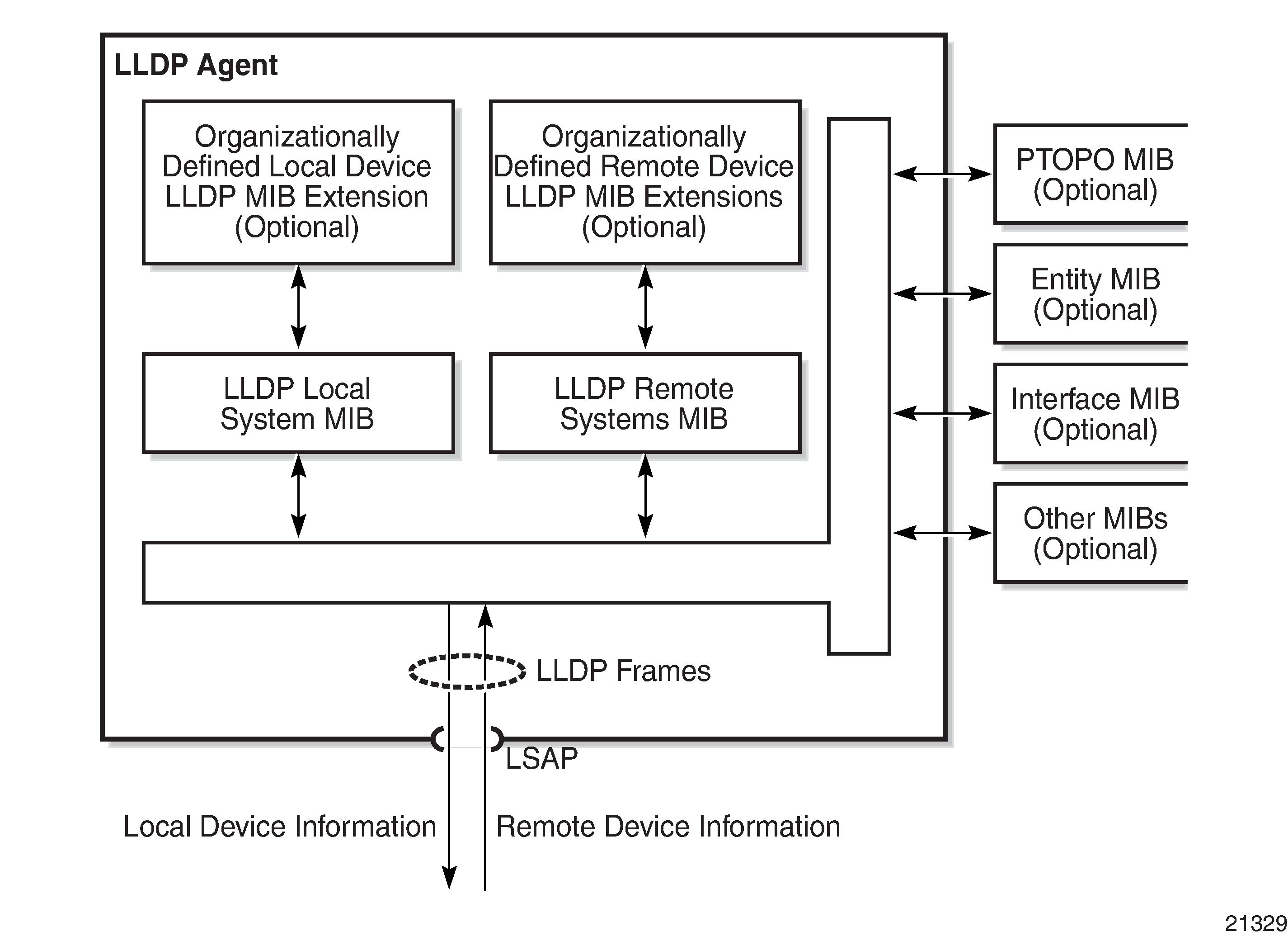
provides compatibility with a number of MIBs as shown in LLDP Internal Architecture for a Network Node
Network operators must be able to discover the topology information in order to detect and address network problems and inconsistencies in the configuration. Standards-based tools can address complex network scenarios where multiple devices from different vendors are interconnected using Ethernet interfaces.
The 7705 SAR platforms, cards, and modules support LLDP on all Ethernet datapath ports. On the 2-port 10GigE (Ethernet) Adapter card/module, LLDP is supported on the Ethernet ports, but not on the v-port. Each Ethernet port can be configured to run up to three LLDP sessions. Each session can have up to five peers and each peer can store up to three management addresses. The 7705 SAR can have a maximum of 720 peers configured.
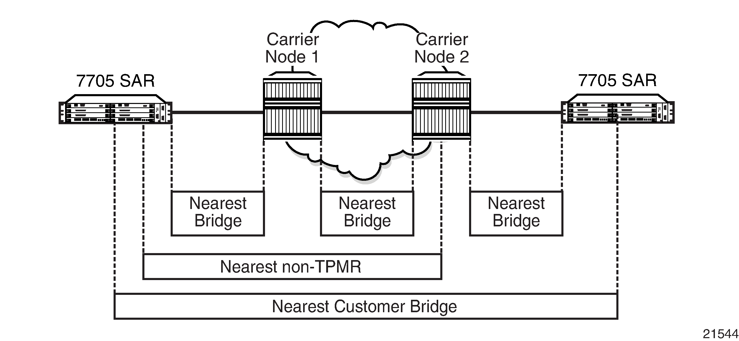
Network Example For LLDP shows the three scopes of LLDP that are supported on the 7705 SAR. The scopes are Nearest Bridge, Nearest non-TPMR Bridge, and Nearest Customer Bridge.
LLDP Protocol Features
LLDP allows stations attached to an IEEE 802 LAN to advertise to other stations attached to the same LAN, the major capabilities provided by the system incorporating that station, the management address or addresses of the entity or entities that manage these capabilities, and the identification of the station's point of attachment to the LAN required by the management entity or entities.
The information distributed via this protocol is stored on the receiving device in a standard MIB, so that the information can be accessed by a Network Management System (NMS).
The LLDP protocol uses an LLDP agent entity that implements LLDP for a particular MAC service access point (MSAP) associated with a port.
LLDP does not contain a mechanism for soliciting specific information from other LLDP agents, nor does it provide a specific means of confirming the receipt of information. LLDP allows the transmitter and the receiver to be enabled separately; therefore, the local LLDP agent can be configured to transmit only, receive only, or both transmit and receive LLDP information.
LLDP agents transmit and receive LLDP Data Units (LLDPDUs). The LLDPDU contains an LLDP frame whose information fields are a sequence of variable-length information elements. Each element includes type, length, and value fields (known as TLVs).
Type identifies what kind of information is being sent.
Length indicates the length of the information string in octets.
Value is the actual information that needs to be sent; for example, a binary bit map or an alphanumeric string that can contain one or more fields.
Each LLDPDU contains four mandatory TLVs and can contain optional TLVs as selected by network management. LLDPDU Format shows the LLDPDU format.
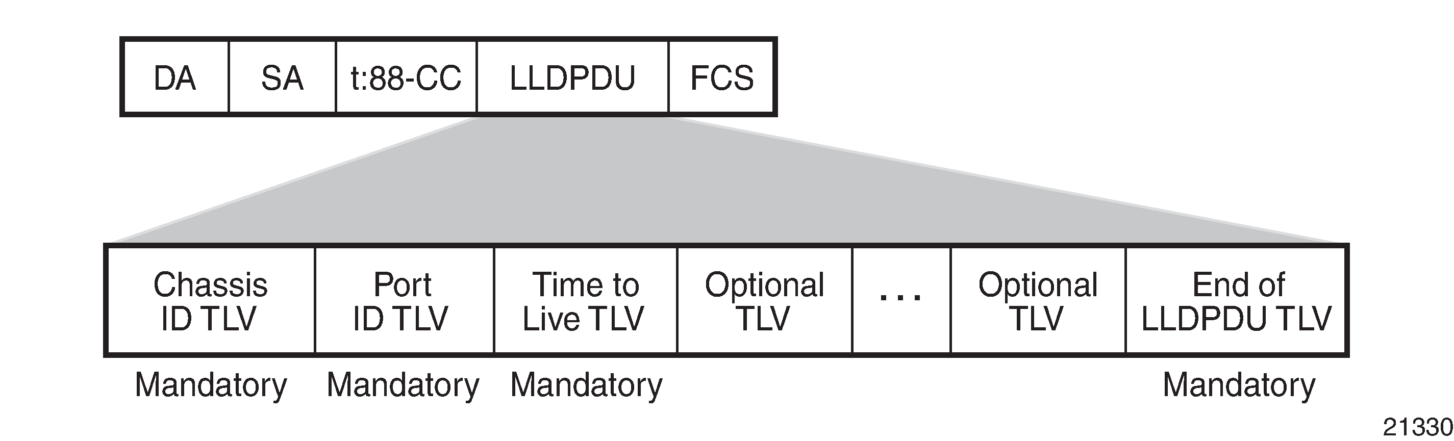
The chassis ID TLV identifies the chassis containing the Ethernet port responsible for transmitting the LLDPDU. The port ID TLV identifies the Ethernet port responsible for transmitting the LLDPDU. The chassis ID and the port ID values are concatenated to form a logical identifier (the MSAP identifier) that is used by the recipient to identify the sending LLDP agent and associated port. Both the chassis ID and port ID values can be defined in a number of ways. Once selected, however, the chassis ID and port ID value combination remains the same as long as the particular port remains operable.
The Time To Live TLV indicates the number of seconds (from 0 to 65535) that the receiving LLDP agent should consider the information contained in the received LLDPDU to be valid. The Time To Live TLV is calculated by the formula tx-interval ✕ tx-hold-multiplier. The associated information is automatically discarded by the receiving LLDP agent if the sender fails to update it before this time. A zero value indicates that any information pertaining to this LLDPDU identifier is to be discarded immediately. A TTL value of zero can be used, for example, to signal that the sending port has initiated a port shutdown procedure.
The End of LLDPDU TLV marks the end of the LLDPDU.
The implementation defaults to setting the port-id field in the LLDP OAMPDU to tx-local. This encodes the port-id field as ifindex (subtype 7) of the associated port, which is required to support some releases of the NSP NFM-P. The NSP NFM-P may use the ifindex value to properly build the Layer 2 topology network map. However, this numerical value is difficult to interpret or readily identify the LLDP peer when reading the CLI or MIB value without using the NSP NFM-P. Including the port-desc option as part of the tx-tlv configuration allows a Nokia remote peer supporting port-desc preferred display logic to display the value in the port description TLV instead of the port-id field value. This does not change the encoding of the port-id field. The port-id field value continues to represent the ifindex. In some environments, it may be important to select the specific port information that is carried in the port-id field. The operator has the ability to control the encoding of the port-id information and the associated subtype using the port-id-subtype option. Three options are supported for the port-id-subtype:
tx-if-alias — transmits the ifAlias string (subtype 1) that describes the port as stored in the IF-MIB, either a user-configured description or the default entry (that is, 10/100/Gig Ethernet SFP)
tx-if-name — transmits the ifName string (subtype 5) that describes the port as stored in the IF-MIB, ifName information
tx-local — the interface ifindex value (subtype 7)
IPv6 (address subtype 2) and IPv4 (address subtype 1) LLDP system management addresses are supported.