Surveillance, Control, and Data Acquisition (SCADA) Support
SCADA systems are used in many strategic industry networks, such as utility and transportation, to monitor and maintain the networks from remote monitoring locations. SCADA systems use a master/slave architecture with a single master that supports multiple slave remote terminal units (RTUs).
Nokia addresses the needs of SCADA customers with the Integrated Services card. The Integrated Services card is a resource card that is capable of supporting software applications that specifically meet the requirements of TDM-based SCADA systems. The card is supported on the 7705 SAR-8 Shelf V2 and the 7705 SAR-18.
The Integrated Services card supports the following SCADA applications:
-
multidrop data bridge (MDDB)
-
pulse code modulation (PCM) multidrop bridge
-
voice conference bridge (VCB)
Only one application can be active on the card at a time.
The MDDB and PCM multidrop bridge applications feature similar architecture and functionality, with the main exception being that the MDDB application uses a serial RS-232, RS-530, or X.21 interface, while the PCM multidrop bridge application uses an E&M analog interface. The VCB application builds on the PCM architecture, using A-Law or Mu-Law encoding and an E&M analog interface.
Multidrop Data Bridge
The MDDB application provides a centralized digital bridging functionality that allows a SCADA bridge to be configured between a master and remote slaves. The bridge allows a single data message stream to be broadcast from a master to multiple slaves and allows a single slave to communicate back to the master.
In a SCADA network, the 7705 SAR provides the communications infrastructure to connect the central masters to multiple RTUs at remote locations, where the masters and RTUs communicate over serial RS-232, RS-530, or X.21 links (synchronous or asynchronous). The 7705 SAR-8 Shelf V2 or 7705 SAR-18 located at the master site contains the Integrated Services card, which provides the MDDB bridge functionality and acts as the MDDB master. Remote 7705 SAR nodes connected to RTUs are referred to as MDDB slaves.
For both master and slave applications, the 7705 SAR must be physically connected to the SCADA device by one of the following:
a 7705 SAR-8 Shelf V2 or 7705 SAR-18 using the 12-port Serial Data Interface card (supports RS-232, RS-530, and X.21 links)
a 7705 SAR-H using the 4-port T1/E1 and RS-232 Combination module (supports RS-232 links only)
a 7705 SAR-Hc using an on-board RS-232 serial port (supports RS-232 links only)
The 12-port Serial Data Interface card, version 2 supports the RS-530/RS-422 interface with the use of an adapter cable that connects to a DB15 connector on the front of the X.21 distribution panel. There is no configuration specifically for the RS-530/RS-422 interface; configuration is done in X.21 mode and applies to the RS-530/RS-422 interface when it is physically enabled through hardware. The 12-port Serial Data Interface card, version 3, provides RS-530 interface capability without the need for an adapter cable. For information about 12-port Serial Data Interface card adapter cables, see the 7705 SAR Serial Data Interface Card Installation Guide.
The remote nodes are connected to the SCADA bridge over an IP/MPLS network.
An Integrated Services card supports up to 16 SCADA bridges. Each bridge supports 32 branches. Two branches (branch 1 and branch 2) are dedicated connections to the SCADA masters; the other 30 branches connect to the slaves. An MDDB SCADA bridge is created using the config>scada bridge-id command and a branch is created using the config>scada>branch branch-id command.
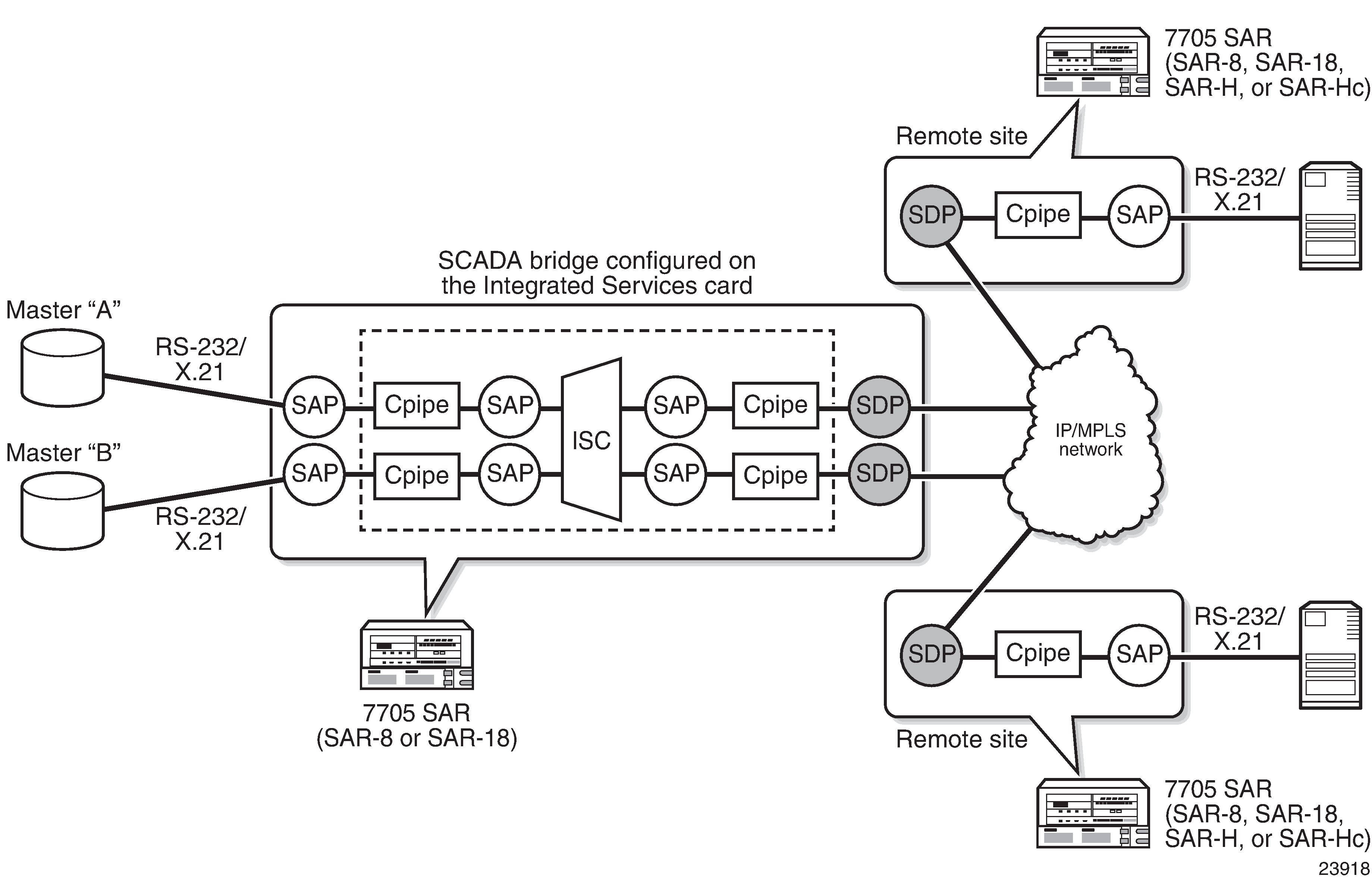
SCADA MDDB Network shows a typical SCADA MDDB network. A Cpipe SAP is configured for each master and slave branch in order to transmit data to the bridge. The RS-232/X.21 traffic is converted to a 64 kb/s Cpipe using high capacity multiplexing (HCM). The Integrated Services card terminates the Cpipe (the slaves send data back over the IP/MPLS network), recovers the data directly from the Cpipe as an HCM frame, and sends the data to the bridge.
PCM Multidrop Bridge
The pulse code modulation (PCM) multidrop bridge application provides multidrop bridging for SCADA systems that use 4-wire analog modems to connect remote slaves to a master. Incoming analog signals from the master are converted to PCM (Mu-Law or A-Law) for transport between a remote slave and the master. The Integrated Services card broadcasts the master stream to all remote slaves. Only the addressed remote unit will respond to the broadcast and the response must be transported through the bridge back to the master via an E&M interface. If the network RTUs support two SCADA systems over the same interface by separating them into high-frequency and low-frequency bands, the PCM multidrop bridge always selects the two loudest branches to be passed through the bridge for communication with the master.
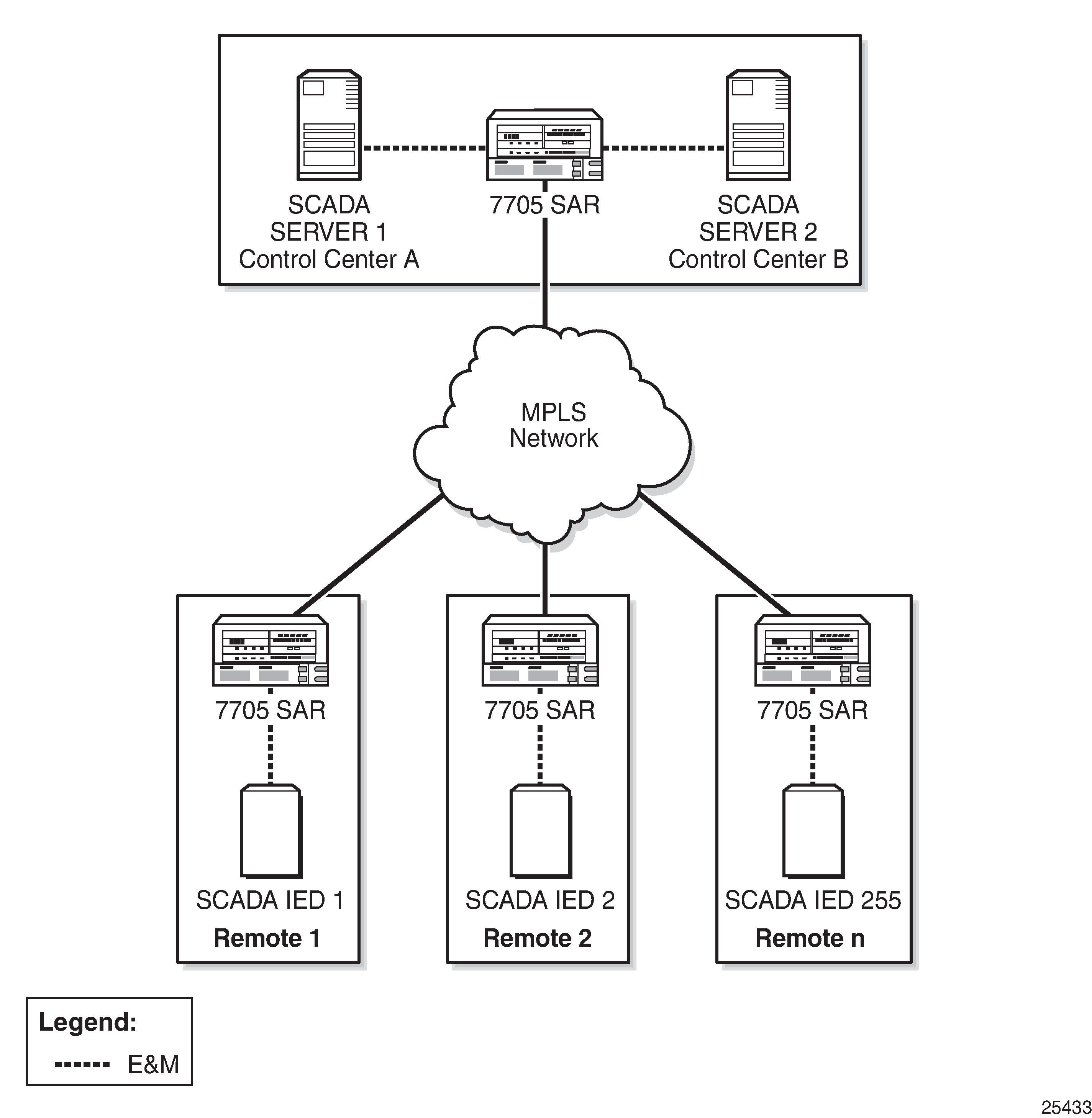
SCADA PCM Multidrop Bridge Network shows a typical SCADA PCM multidrop bridge network.
The PCM multidrop bridge application uses Mu-Law and A-Law encoding; therefore, the modularity is different from MDDB modularity. PCM Multidrop Bridge Modularity shows the modularity for a PCM multidrop bridge on the Integrated Services card.
Encoding Scheme |
Number of Bridges per Integrated Services Card |
Number of Branches per Bridge |
Total Number of Branches per Integrated Services Card |
|---|---|---|---|
Mu-Law (North America) |
16 |
22 |
352 |
A-Law (rest of world) |
16 |
30 |
480 |
A PCM SCADA bridge is created using the config>scada bridge-id command and a branch is created using the config>scada>branch branch-id command.
Redundant Masters
The MDDB and PCM multidrop bridge applications support redundant masters, where both masters listen to all traffic that is being transmitted from the slaves but only the active master broadcasts data to the slaves.
There are two modes for master redundancy:
manual (default mode)
In manual mode, if a master branch fails, the second master branch must be made active manually with the force-active command in order to receive data from the master input. The bridge always broadcasts to both master branches.
auto
In auto mode, both master branch inputs are received simultaneously. This requires the master input behavior to be similar to an RTU; that is, only the active master transmits data and the standby master transmits either all 1s (MDDB) or no data (PCM). If the bridge is in auto mode, the force-active command cannot be used.
Squelch Functionality
A condition may occur where a single slave continues to send data to the master after the normal response period has expired. This condition locks up the bridge so that no other slave can transmit data back to the master. To resolve this condition, the squelch command can be enabled on a bridge or on an individual slave or master branch. Squelch is enabled by configuring a timeout period that, once expired, raises an alarm and triggers the squelching function. A normal quiescent traffic pattern (all 1s for MDDB and low volume for PCM multidrop) is inserted towards the bridge. This blocks the problematic slave so that other slaves can continue to use the bridge.
In order to put the bridge into the normal state, it must be reset. This can be manually initiated by the operator with the squelch reset command, or it can occur automatically after a configured time if the squelch-recovery command is set to auto.
For MDDB, because different algorithms are needed to detect squelch conditions at low-speed and high-speed rates, interface speed selection is required. The interface speed is set at the bridge level.
Voice Conference Bridge
The voice conference bridge (VCB) application provides a simultaneous communication path between two or more voice circuits. VCBs are deployed in a central location with remote devices connected to the bridge via the 7705 SAR over an IP/MPLS or TDM network. Inputs to the VCB are 4-wire E&M analog interfaces.
VCBs can be used as a conference bridge with any-to-any connectivity (all branches participate) or as a bridge in broadcast mode where one branch broadcasts to the other branches that are in listen-only mode.
The main VCB applications are:
Land Mobile Radio (LMR) interconnection
Both voice conference mode and broadcast mode can be used for this application.
analog multi-terminal teleprotection interconnect for electrical utilities
For multi-terminal teleprotection applications, VCBs allow all teleprotection relays to communicate with each other in order to make the appropriate switching decision in the event of a fault.
The VCB application uses Mu-Law and A-Law encoding, similar to PCM. VCB Modularity shows the modularity for a VCB on the Integrated Services card.
Encoding Scheme |
Number of Bridges per Integrated Services Card |
Number of Branches per Bridge |
Total Number of Branches per Integrated Services Card |
|---|---|---|---|
Mu-Law (North America) |
16 |
24 |
384 |
A-Law (rest of world) |
16 |
32 |
512 |
A VCB SCADA bridge is created using the config>scada bridge-id command and a branch is created using the config>scada>branch branch-id command.
VCB Applications
VCB can be configured in one of four applications. These applications are set at the card level. Each application uses a bridging algorithm that determines which branches control the management of the bridge and transmission of signals:
VCB
One branch talks and all other branches on the bridge can hear.
broadcast
Only one branch on the bridge (fixed as branch 1) has control of the bridge to transmit, and all other branches are in listen-only mode.
VCB branch initiate
Branches on the bridge are only enabled (unmuted) when the attached base station signals its presence by grounding the M-lead on the interface connected to the bridge. Upon receiving the grounded M-lead via T1/E1 ABCD bits or TDM PW signaling, the bridge unmutes the associated branch. When the ground is removed, the branch is muted again.
teleprotection
Each teleprotection relay transmits state information on discrete frequencies so that each relay can both hear what the other relays are transmitting as well as transmit its own information to the other relays.
VCB Mute Output Option
The 7705 SAR supports the VCB mute transmission output option on all VCB applications. By default, a branch transmission is broadcast to all other branches on the bridge. The mute output option blocks the transmission to a branch.
Each branch of the VCB has a SAP with an associated Cpipe that connects to an SDP or SAP. The operator can mute the output from a branch with the config>service>cpipe>sap>cem>mute-output command. When mute-output is enabled, nothing is transmitted out that branch of the VCB, meaning that none of the connected sites can hear the transmission.
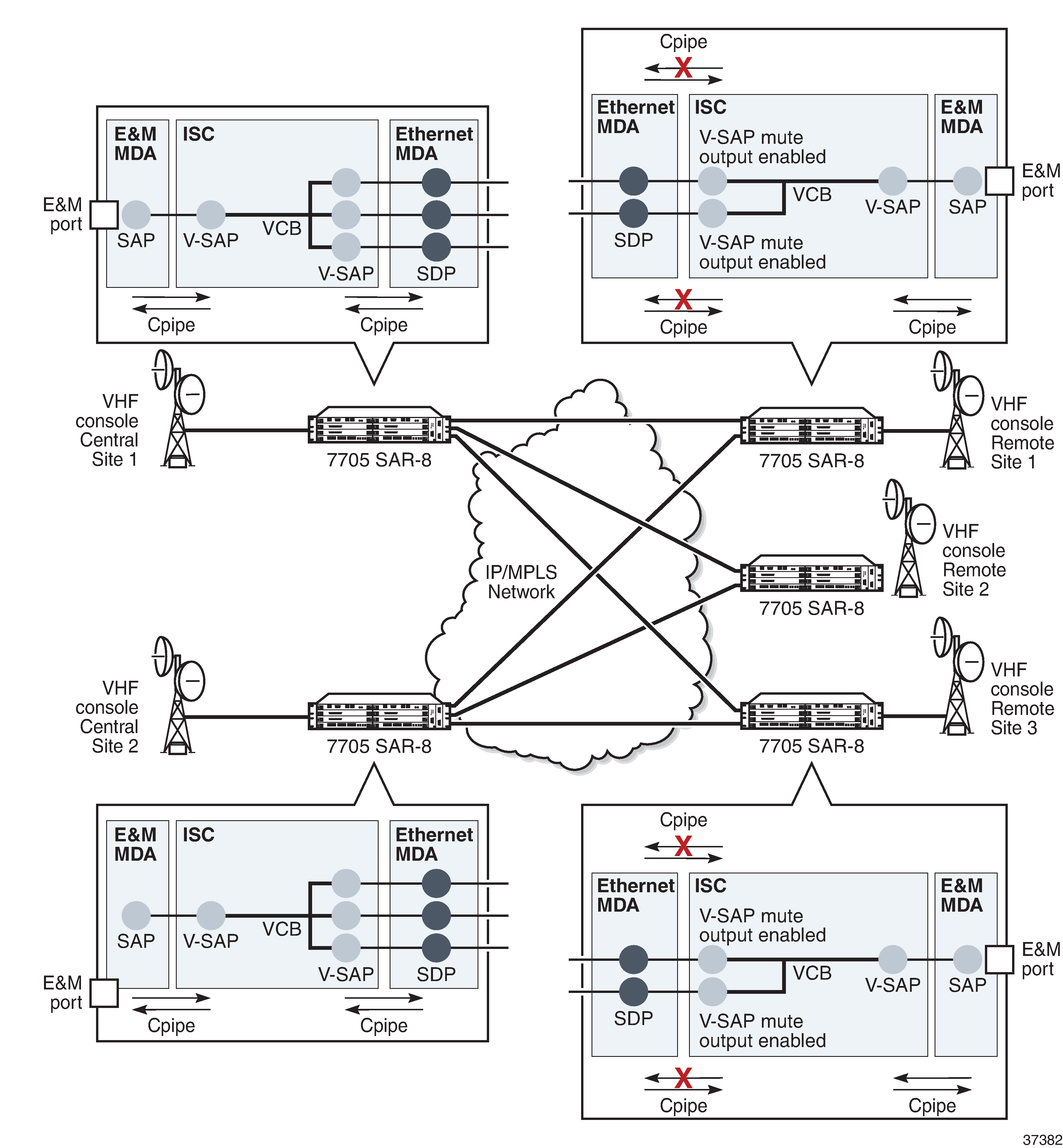
For example, to configure a network where any remote site can initiate transmission but none of the remote sites can hear what is transmitted, only the central sites can listen, mute-output must be enabled on the SAPs of the branches on the Integrated Services cards at the central site toward the remote sites. Similarly, to configure a network where any central site can initiate transmission but only the remote sites can listen, mute-output must be enabled on the SAPs of the branches on the Integrated Services cards at the remote site toward the central sites.
VCB Mute Output Toward Central Sites Example shows an example where only the remote sites can listen to the transmission.
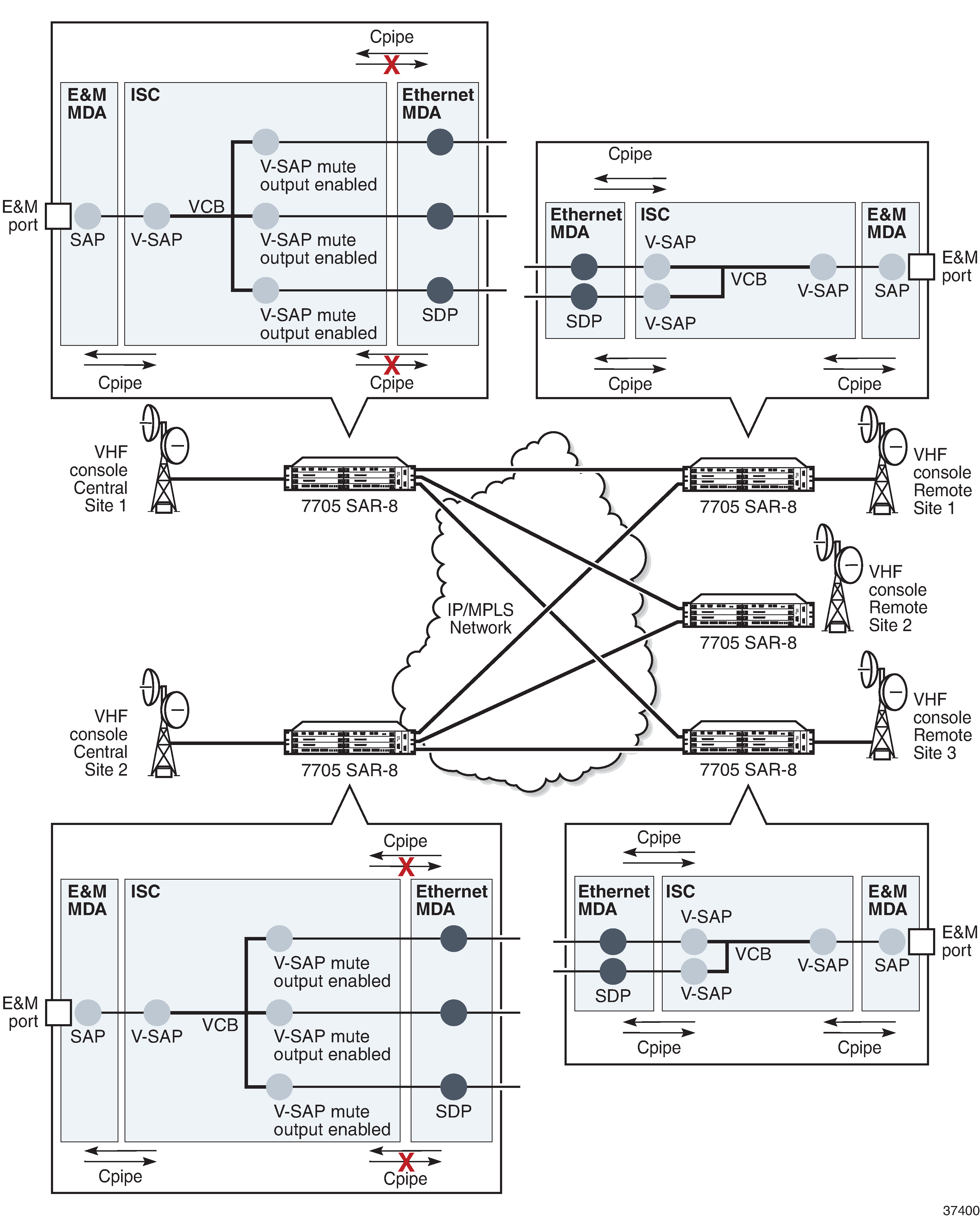
VCB Mute Output Toward Remote Sites Example shows an example where only the central sites can listen to the transmission.
Gain
Gain is the increase or decrease in signal power or voltage that occurs in transmitting a signal from one point to another. The two types of gain are:
input
output
Gain is configured at the branch level.
The input gain defines the magnitude of the increase or decrease of the signal transmitted into the bridge. The input gain range is –16 to +9 dB in 1-dB increments (the default is 0 dB).
The output gain defines the magnitude of the increase or decrease of the signal received from the bridge. The output gain range is –16 to +9 dB in 1-dB increments (the default is 0 dB).
Serial Transport Over Raw Sockets
Serial transport over raw sockets provides the capability of transporting serial data, in the form of characters, over an IP transport service within a Layer 3 IP/MPLS service (IES or VPRN). A raw socket allows direct sending and receiving of IP packets without any protocol-specific transport layer formatting. For information about raw socket IP transport services, refer to the 7705 SAR Services Guide, Service Overview chapter, ‟Raw Socket IP Transport Service”.
The feature provides the functionality for a local host to listen to and open raw socket sessions from remote hosts, and for a remote host to initiate and open raw socket sessions to local hosts. The local and remote host functions support TCP or UDP sessions (but not both concurrently) over the IP transport service.
Raw sockets are supported on the following hardware:
RS-232 ports on the 12-port Serial Data Interface card, version 2 and version 3
RS-232 ports on the 7705 SAR-Hc
RS-232 ports on the 4-port T1/E1 and RS-232 Combination module
RS-232 serial data can be carried over Cpipes or over raw sockets using IP transport. To use Cpipes, the RS-232 port must be configured with a channel ID. To use raw sockets, the RS-232 port must be configured with a socket ID.
The 12-port Serial Data Interface card supports a mix of Cpipes and raw socket serial links on the same card.
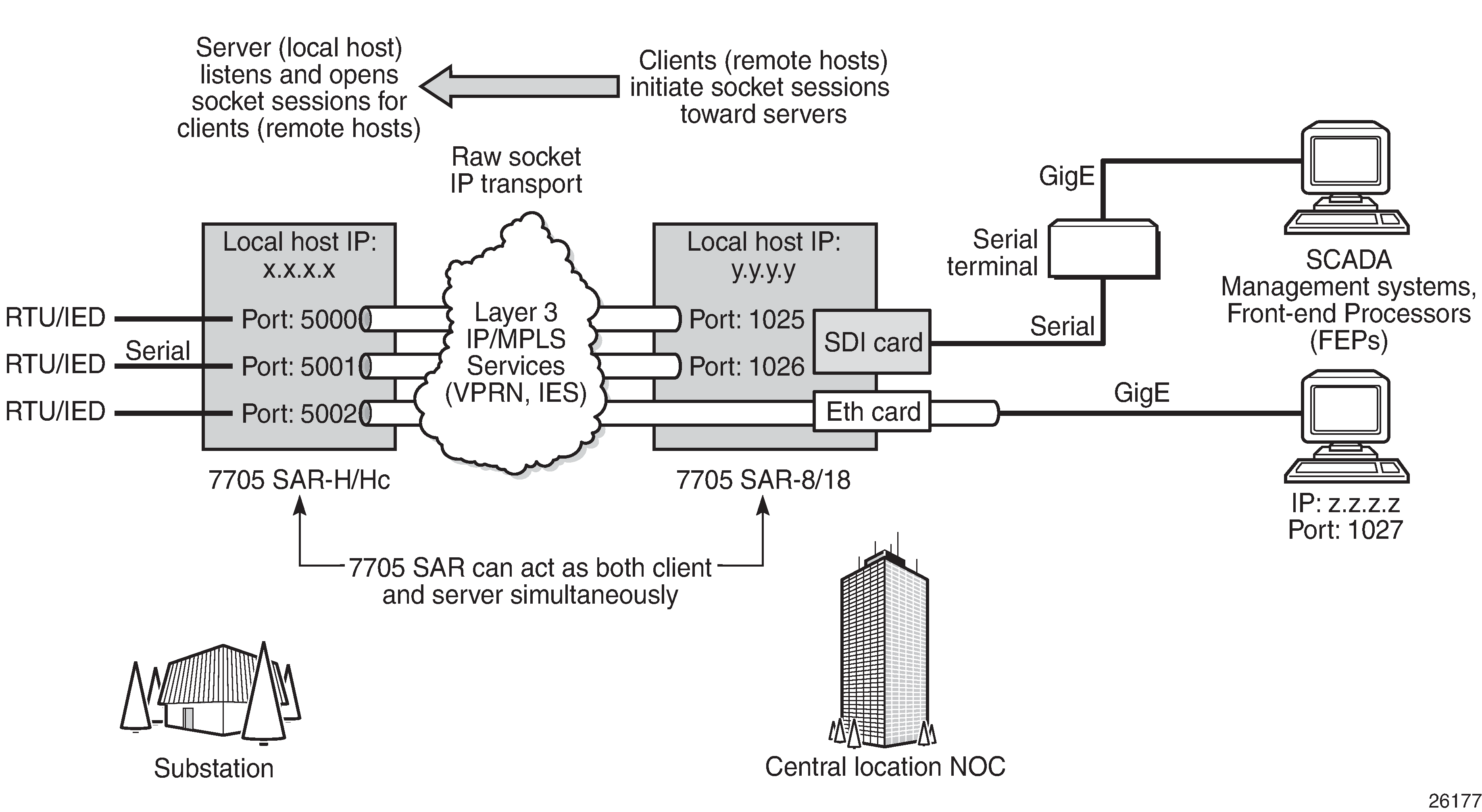
Serial Transport Over Raw Socket Application shows an example of a raw socket application, where serial data is transferred between RTUs and a utility’s SCADA management system using an IP transport service across a Layer 3 service (IES or VPRN), that includes 7705 SAR-H or 7705 SAR-Hc and 7705 SAR-8 Shelf V2 or 7705 SAR-18 nodes.
A raw socket local host (acting as a server) at the 7705 SAR-H/SAR-Hc substation listens to TCP sessions that originate at the 7705 SAR-8 Shelf V2/SAR-18 central location network operations center (NOC). The 7705 SAR-8 Shelf V2/SAR-18 at the NOC is connected to two front-end processors (FEPs), one via a serial port and another via an Ethernet port. The serial port on the 7705 SAR-8 Shelf V2/SAR-18 is configured as a remote host (acting as a client) that initiates TCP/UDP sessions towards the RTU at the 7705 SAR-H/SAR-Hc substation when traffic is received from the FEP over the serial port. These TCP/UDP sessions are transported over the IP/MPLS network using IP transport service over an IES or VPRN service. The serial data that is transported over the TCP/UDP session and received at the 7705 SAR-H/SAR-Hc is then sent over the serial link towards the RTU. TCP/UDP sessions received from the FEP over the Ethernet port are transported over an IES or VPRN service (that is, there is no need for serial remote host configuration in this case).
Multiple FEPs can poll a single RTU. If multiple sessions attempt to transmit serial data on the serial port simultaneously, the 7705 SAR queues packets per session and ensures that all data for one session is sent out before processing another session’s data, ensuring that sessions do not overlap one another.
Raw Socket Configuration
A raw socket IP transport interface can be configured for each RS-232 serial port on a node. This allows the serial port to receive TCP connections or UDP session packets from multiple remote hosts, or to create new sessions to remote hosts in order to send and receive serial data to and from those remote hosts.
There are port-level and service-level configuration requirements for a raw socket serial port to send and receive serial data in either server mode, client mode, or both.
Raw socket port-level configuration includes defining the end-of-packet checking parameters (idle-time, length, special character) and the inter-session delay for transmitting session data over the serial link. See Serial Commands for the required information.
At the service level, an IP transport subservice is created within an IES or VPRN service to associate the serial port with the respective IES or VPRN service. TCP/UDP encapsulated serial data is routed within the corresponding Layer 3 IES or VPRN service. The required configuration includes IP transport subservice local-host and remote-host configuration, TCP timers, and session control. Refer to the 7705 SAR Services Guide, ‟IES Raw Socket IP Transport Configuration Commands” and ‟VPRN Raw Socket IP Transport Configuration Commands” for the required information.
Raw Socket Packet Processing
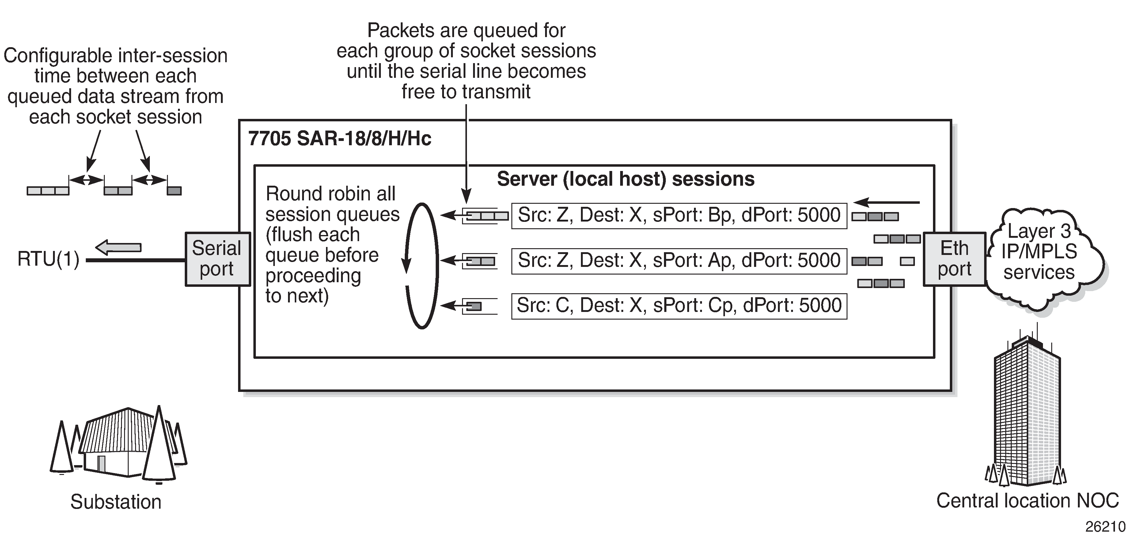
Raw Socket Packet Processing illustrates how raw socket packets are processed over a serial link.
Session data attempting to access the serial port is queued. One queue is maintained per session. The purpose of the session queue is to prevent two different flows of packets from interleaving out the serial port and creating unreadable messages. When data is being transmitted over the serial link for a session, any other session’s data is queued until the first session has emptied its queue. The next session’s data is transmitted over the serial link only after the inter-session-delay timer expires. Each session’s data is sent out in round-robin fashion.
Raw Socket Processing for UDP Sessions
When the local host receives a UDP packet from a remote host, it queues the packet and sends it over the serial link. The local host remembers the UDP session while there is still data to send from the serial link. If further packets are received for the same session, they are queued behind the already queued packet. After all the queued data has been sent over the serial link, the session is removed from the system. An associated UDP remote host for the serial link must be configured to have serial data sent back to the remote host from the serial port.
When a packet is received from the serial link based on end-of-packet (EOP) requirements, the data is copied and sent in a UDP packet to each configured remote host.
Raw Socket Processing for TCP Sessions
An open TCP session from a remote host to a raw socket’s local host is kept open until either the remote host terminates the session or the TCP inactivity timer expires. When a TCP session is open, all packets received from the remote host are queued for the raw socket serial link and sent over the serial link until no packets remain in the queue.
If multiple sessions are open towards the local host, and each is receiving data, each session’s data is queued and then sent over the serial link in round-robin fashion for each session until no packets remain. When a packet is received over the serial link, it is copied to each open TCP session and transmitted to the remote host.
Raw Socket Squelch Functionality
A condition may occur where the end device connected to the serial port continues to send out a continuous stream of data after the normal response period has expired. This can prevent the far-end remote host or master equipment from receiving data from other end devices in the network. To resolve this condition, the squelch command can be used on the raw socket at the port level (it is disabled by default). This stops the socket from receiving any more data from the problematic device.
If the command is enabled, the 7705 SAR will monitor the serial port for a constant character stream. A configurable squelch delay period, using the squelch-delay command, is used to determine how long to measure the constant character stream before initiating the squelch function. If the squelch function is initiated, the port is considered locked up and an alarm is raised indicating the lock-up and that the squelching function has been triggered.
The serial port can be forced out of squelch and put back to normal, either manually using the squelch-reset command or automatically using the unsquelch-delay command. The unsquelch-delay command defines the time to wait after squelch is initiated before it is removed.