Configuration Overview
This guide uses the term ‟preprovisioning” in the context of preparing or preconfiguring entities such as chassis slots, the IOM, adapter cards, ports, and interfaces, prior to hardware actually being installed in the chassis. These entities can be installed but not enabled. When the entity is in a no shutdown state (administratively enabled), the entity is considered to be provisioned.
Nokia 7705 SAR routers provide the capability to configure chassis slots to accept specific adapter card types and set the relevant configurations before the equipment is actually installed. The preprovisioning ability allows you to plan your configurations as well as monitor and manage your router hardware inventory. Ports and interfaces can also be preprovisioned. When the functionality is needed, the cards can be inserted into the appropriate chassis slots as required.
The following sections are discussed:
Configuring the IOM and Card Slot
The 7705 SAR card slot ID is always 1 and the card type for the IOM is always iom-sar.
On the 7705 SAR-8 Shelf V2 and 7705 SAR-18, the CSM, which can only be installed in slot A or B of the chassis, does not need to be provisioned. However, the IOM, which is virtualized in the 7705 SAR software, must be activated before the adapter cards, ports, and SCADA bridges can be preprovisioned and configured. The IOM is activated by designating it a card slot ID and card type. This enables the chassis slots to accept the adapter cards.
The 7705 SAR-M, 7705 SAR-H, 7705 SAR-Hc, 7705 SAR-A, 7705 SAR-Ax, 7705 SAR-Wx, and 7705 SAR-X have a fixed physical configuration and each router uses only one control and switching functional block, which is referred to on the CLI as CSM A. The CSM and IOM do not need to be provisioned in order to provision the interface at the adapter card level.
The slot ID (1) is used as part of the adapter card and port identifier on the CLI.
Configuring Adapter Cards and Modules
This section contains information on the following topics:
Provisioning Chassis Slots for Adapter Cards
A chassis slot and card type must be specified and provisioned before an adapter card can be provisioned. A chassis slot is a physical slot designated with an MDA ID. On the 7705 SAR-8 Shelf V2, the MDA ID is from 1 to 6. On the 7705 SAR-18, the MDA ID is from 1 to 12 for the MDA slots and from X1 to X4 for the XMDA slots. An adapter card is provisioned when a card designated from the allowed adapter card types is inserted. A preprovisioned adapter card slot can remain empty without conflicting with populated slots.
The adapter cards can be installed in the chassis in any combination that does not exceed the maximum number. However, network applications require at least one network-capable adapter card to be installed.
Once installed and enabled, the system verifies that the installed adapter card type matches the configured parameters. If the parameters do not match, the adapter card remains offline.
Maximum Number of Adapter Cards in a Chassis
A maximum of six adapter cards can be installed in the 7705 SAR-8 Shelf V2 chassis. The following adapter cards are supported:
2-port 10GigE (Ethernet) Adapter card (maximum of 4)
2-port OC3/STM1 Channelized Adapter card (maximum of 6, depending on channelization – see note below)
4-port OC3/STM1 / 1-port OC12/STM4 Adapter card (maximum of 6)
4-port OC3/STM1 Clear Channel Adapter card (maximum of 6)
4-port DS3/E3 Adapter card (maximum of 6, depending on channelization – see note below)
6-port E&M Adapter card (maximum of 6)
6-port FXS Adapter card (maximum of 6)
6-port Ethernet 10Gbps Adapter card (maximum of 6)
8-port FXO Adapter card (maximum of 6)
8-port Gigabit Ethernet Adapter card (maximum of 6)
8-port Voice & Teleprotection card (maximum of 6)
8-port C37.94 Teleprotection card (maximum of 5)
12-port Serial Data Interface card (maximum of 6)
16-port T1/E1 ASAP Adapter card (maximum of 6)
32-port T1/E1 ASAP Adapter card (maximum of 6)
Auxiliary Alarm card (maximum of 6)
CWDM OADM Adapter card (maximum of 6)
GNSS Receiver card (maximum of 2)
Integrated Services card (maximum of 6)
Packet Microwave Adapter card (maximum of 6)
Power Injector card (maximum of 4)
A maximum of 12 MDA adapter cards and 4 XMDA adapter cards can be installed in the 7705 SAR-18 chassis. The following adapter cards are supported:
2-port 10GigE (Ethernet) Adapter card (maximum of 6)
2-port OC3/STM1 Channelized Adapter card (maximum of 12, depending on channelization – see note below)
4-port OC3/STM1 / 1-port OC12/STM4 Adapter card (maximum of 12)
4-port OC3/STM1 Clear Channel Adapter card (maximum of 12)
4-port DS3/E3 Adapter card (maximum of 12, depending on channelization – see note below)
6-port E&M Adapter card (maximum of 12)
6-port FXS Adapter card (maximum of 12)
6-port Ethernet 10Gbps Adapter card (maximum of 12)
8-port FXO Adapter card (maximum of 12)
8-port Gigabit Ethernet Adapter card (maximum of 12)
8-port Voice & Teleprotection card (maximum of 12)
8-port C37.94 Teleprotection card (maximum of 11)
10-port 1GigE/1-port 10GigE X-Adapter card (maximum of 4)
12-port Serial Data Interface card (maximum of 12)
16-port T1/E1 ASAP Adapter card (maximum of 12)
32-port T1/E1 ASAP Adapter card (maximum of 12)
Auxiliary Alarm card (maximum of 12)
CWDM OADM Adapter card (maximum of 12)
GNSS Receiver card (maximum of 2)
Integrated Services card (maximum of 12)
Packet Microwave Adapter card (maximum of 12)
Power Injector card (maximum of 8)
On a 7705 SAR-8 Shelf V2 chassis:
a maximum of six 2-port OC3/STM1 Channelized Adapter cards can be installed in MDA slots 1 to 6 if DS3 channelization is being used. If DS1/E1 or DS0 (64 kb/s) channelization is being used, a maximum of four 2-port OC3/STM1 Channelized Adapter cards can be installed in MDA slots 1 to 6.
a maximum of six 4-port DS3/E3 Adapter cards can be installed in MDA slots 1 to 6 if DS3/E3 or DS1/E1 channelization is being used. If DS0 (64 kb/s) channelization is being used, a maximum of four 4-port DS3/E3 Adapter cards can be installed in MDA slots 1 to 6.
a maximum of six 4-port OC3/STM1 / 1-port OC12/STM4 Adapter cards can be installed in MDA slots 1 to 6 if DS1/E1 channelization is being used. DS0 and DS3/E3 channelization is not supported on the 4-port OC3/STM1 / 1-port OC12/STM4 Adapter card.
a maximum of six 6-port Ethernet 10Gbps Adapter cards can be installed in MDA slots 1 to 6. When installed in MDA slot 1 or 2, the 6-port Ethernet 10Gbps Adapter card supports a 10-Gb/s fabric rate. When installed in MDA slots 3 through 6, the aggregate fabric rate is 2.5 Gb/s.
On a 7705 SAR-18 chassis:
a maximum of twelve 2-port OC3/STM1 Channelized Adapter cards can be installed in MDA slots 1 to 12 if DS3 channelization is being used. If DS1/E1 or DS0 (64 kb/s) channelization is being used, a maximum of four 2-port OC3/STM1 Channelized Adapter cards can be installed in MDA slots 1 to 12.
a maximum of twelve 4-port DS3/E3 Adapter cards can be installed in MDA slots 1 to 12 if DS3/E3 or DS1/E1 channelization is being used. If DS0 (64 kb/s) channelization is being used, a maximum of four 4-port DS3/E3 Adapter cards can be installed in MDA slots 1 to 12.
a maximum of twelve 4-port OC3/STM1 / 1-port OC12/STM4 Adapter cards can be installed in MDA slots 1 to 12 if DS1/E1 channelization is being used. DS0 and DS3/E3 channelization is not supported on the 4-port OC3/STM1 / 1-port OC12/STM4 Adapter card.
The total number of channel groups that can be configured per card and per node is bound by release-specific system limits. For more information, please contact your Nokia technical support representative.
Evolution of Ethernet Adapter Cards, Modules, and Platforms
The 7705 SAR hardware components have improved as technology has developed. Ethernet Adapter Card, Module, and Platform Generations lists the Ethernet adapter cards, modules, and platforms according to their generation. Second-generation (Gen-2) components have additional features, increased card memory and/or improved QoS mechanisms over previously supported first-generation components. Similarly, third-generation (Gen-3) components improve upon second-generation components.
Generation |
Card, Module, and Platform |
|---|---|
|
Second Generation |
2-port 10GigE (Ethernet) Adapter card (v-port) |
2-port 10GigE (Ethernet) module (v-port) (for 7705 SAR-M) |
|
8-port Gigabit Ethernet Adapter card |
|
10-port 1GigE/1-port 10GigE X-Adapter card |
|
Packet Microwave Adapter card |
|
7705 SAR-A |
|
7705 SAR-Ax |
|
7705 SAR-H |
|
7705 SAR-Hc |
|
7705 SAR-M |
|
7705 SAR-Wx |
|
4-port SAR-H Fast Ethernet module |
|
6-port SAR-M Ethernet module |
|
Third Generation |
6-port Ethernet 10Gbps Adapter card |
7705 SAR-X |
Channelized Adapter Card Support
The following cards and modules support channelization down to the DS0 level:
16-port T1/E1 ASAP Adapter card
32-port T1/E1 ASAP Adapter card
12-port Serial Data Interface card
6-port E&M Adapter card
2-port OC3/STM1 Channelized Adapter card
4-port DS3/E3 Adapter card
8-port Voice & Teleprotection card
8-port C37.94 Teleprotection card
8-port FXO Adapter card
6-port FXS Adapter card
4-port T1/E1 and RS-232 Combination module
On the 16-port T1/E1 ASAP Adapter card, 32-port T1/E1 ASAP Adapter card, 2-port OC3/STM1 Channelized Adapter card, and 4-port DS3/E3 Adapter card (DS3 ports only), and on the T1/E1 ports of the 4-port T1/E1 and RS-232 Combination module, up to 24 channel groups are supported on a DS1 circuit and up to 32 channel groups on an E1 circuit.
The 12-port Serial Data Interface card supports a single channel group on a channelized V.35 circuit, RS-530, RS-232 (also known as EIA/TIA-232) circuit, or X.21 circuit. The RS-232 ports on the 4-port T1/E1 and RS-232 Combination module also support a single channel group on a channelized RS-232 circuit.
The 6-port E&M Adapter card supports a single channel group on a channelized E&M voice interface.
The 8-port Voice & Teleprotection card supports a single channel group on a channelized G.703 (codirectional) circuit, an IEEE C37.94 teleprotection interface (TPIF) circuit, FXS circuit, or FXO circuit.
The 8-port C37.94 Teleprotection card supports a single channel group on an IEEE C37.94 teleprotection interface (TPIF) circuit.
The 8-port FXO Adapter card supports a single channel group on an FXO circuit.
The 6-port FXS Adapter card supports a single channel group on an FXS circuit.
The 4-port OC3/STM1 / 1-port OC12/STM4 Adapter card supports channelization at the DS1/E1 level only.
PPP Over Fractional T1/E1
The 16-port T1/E1 ASAP Adapter card, 32-port T1/E1 ASAP Adapter card, and the T1/E1 ports on the 4-port T1/E1 and RS-232 Combination module each support fractional T1/E1 on a PPP channel group in network mode. Fractional T1/E1 allows one or more DS0 channels to be bundled together (up to the maximum bandwidth of the network link), allowing the customer to use only that portion of the link that is needed. This means that the PPP service can use a selected number of timeslots (octets) in the network T1 or E1 link, therefore reducing the amount of T1 or E1 bandwidth that must be leased or purchased from the attached carrier. This leads to multiplexing efficiencies in the transport network.
Only one channel group can be configured per port. When the channel group is configured for ppp-auto encapsulation and network mode, all timeslots (channels) are automatically allocated to the channel group. The user can then configure the number of timeslots needed. Timeslots not selected cannot be used.
Configuring Ports
A port can be configured after the IOM is activated (the card slot and card type are designated) and the adapter card slot is preprovisioned with an allowed adapter card type.
The 7705 SAR supports the port types listed below:
In addition, this section contains information on the following topics:
Ethernet
Ethernet ports are supported on the following cards, modules, and platforms:
6-port Ethernet 10Gbps Adapter Card
The 6-port Ethernet 10Gbps Adapter card has four SFP ports for 1-Gb/s fiber or copper SFP transceivers and two SFP+ ports for 10-Gb/s fiber or copper SFP+ transceivers. The card also supports synchronous Ethernet timing. The 6-port Ethernet 10Gbps Adapter card is designed to complement or replace the 8-port Gigabit Ethernet Adapter card in situations where greater processing power and higher throughput capacity are required.
There are two versions of this card: 6-port Ethernet 10Gbps Adapter card and 6-port Ethernet 10Gbps Adapter card-E. The versions have identical functionality except that the 6-port Ethernet 10Gbps Adapter card-E does not have encryption functionality.
The ports and features on the 6-port Ethernet 10Gbps Adapter card are identical to the ports and features on the 8-port Gigabit Ethernet Adapter card, version 3, except that the 6-port Ethernet 10Gbps Adapter card uses only 4-priority schedulers for QoS instead of 4-priority or 16-priority schedulers.
8-port Gigabit Ethernet Adapter Card
The 8-port Gigabit Ethernet Adapter card has eight SFP ports for fiber or copper SFPs. The card supports dual rate (100 Mb/s and 1000 Mb/s) and Gigabit (1000 Mb/s) fiber connections and 10/100/1000Base-T copper connections. The card also supports synchronous Ethernet timing.
There are three versions of the 8-port Gigabit Ethernet Adapter card. Version 1 and version 2 are identical except that version 2 provides larger table space for FIBs, ACLs, and so on. Version 2 also supports the full IPv6 subnet range for IPv6 static routes and interface IP addresses. The static route range is from /1 to /128, and the default route is ::/0. Supported interface IP address prefixes are from /4 to /127, and /128 on system or loopback interfaces. Version 3 is identical to version 2 except that it is equipped with a hardware-based encryption engine to support features such as IPSec.
Higher limits and full subnet ranges are supported only when all the adapter cards in a particular node are equipped with hardware for larger table support.
Gigabit Ethernet optical ports offer significant advantages over fast Ethernet ports, even where lower-speed services are currently offered. With Gigabit Ethernet, service providers have the opportunity to standardize access infrastructure, ensure that capacity is available to accommodate growing bandwidth requirements, and minimize the operational costs associated with future service upgrades to hardware and software.
10-port 1GigE/1-port 10GigE X-Adapter Card
There are two versions of the 10-port 1GigE/1-port 10GigE X-Adapter card. Both versions are identical except that version 2 is equipped with a hardware-based encryption engine to support features such as IPSec. The card is supported only on the 7705 SAR-18.
The 10-port 1GigE/1-port 10GigE X-Adapter card has 10 small form-factor pluggable (SFP) ports on its faceplate.
When the 10-port 1GigE/1-port 10GigE X-Adapter card is configured in 10-port GigE mode, the 10 SFP ports are available for fiber SFP transceivers. In this mode, the card supports dual-rate (100 Mb/s and 1000 Mb/s) and Gigabit (1000 Mb/s) fiber connections. The card also supports synchronous Ethernet timing.
When the 10-port 1GigE/1-port 10GigE X-Adapter card is configured in 1-port GigE mode, only one SFP+ (port 1) of the 10 ports is active and available for use with fiber SFP+ transceivers. The card supports 10-Gb/s fiber connections. The card also supports synchronous Ethernet timing. The 1-port GigE mode is designed for use in situations where greater processing power and higher throughput capacity are required.
The 10-port 1GigE/1-port 10GigE X-Adapter card provides larger table space for FIBs, ACLs, and so on. The card also supports the full IPv6 subnet range for IPv6 static routes and interface IP addresses. The static route range is from /1 to /128, and the default route is ::/0. Supported interface IP address prefixes are from /4 to /127, and /128 on system or loopback interfaces.
Higher limits and full subnet ranges are supported only when all the adapter cards in a particular node are equipped with hardware for larger table support.
2-port 10GigE (Ethernet) Adapter Card/Module
The 2-port 10GigE (Ethernet) Adapter card/module is used to connect to and from access rings carrying a high concentration of traffic. Maximum Number of Cards/Modules Supported in Each Chassis lists the maximum number of cards or modules that are supported on each platform. A single card can be installed in the 7705 SAR-8 Shelf V2 or the 7705 SAR-18; however, it is strongly recommended that a minimum of two cards be installed for redundancy.
Chassis |
Maximum Number of Cards or Modules |
|---|---|
7705 SAR-8 Shelf V2 |
Up to four cards |
7705 SAR-18 |
Up to six cards |
7705 SAR-M |
One module |
The 2-port 10GigE (Ethernet) Adapter card/module has two small form-factor pluggable (XFP) ports on its faceplate. The two XFP ports are for 10-Gigabit Ethernet XFPs. The card provides high processing power and throughput capacity and operates at 10 Gb/s for Ethernet ports and 2.5 Gb/s for the virtual port (v-port).
The 2-port 10GigE (Ethernet) Adapter card provides larger table space for FIBs, ACLs, and so on. The card also supports the full IPv6 subnet range for IPv6 static routes and interface IP addresses on the v-port. The supported range for statically provisioned or dynamically learned routes is from /1 to /128. Supported interface IP address prefixes are from /4 to /127, and /128 on system or loopback interfaces.
The 2-port 10GigE (Ethernet) module supports IPv6 on the v-port. The supported range for statically provisioned or dynamically learned routes is from /1 to /64 or is /128 (indicating a host route). Supported interface IP address prefixes are from /4 to /64, and /128 on system or loopback interfaces.
The 2-port 10GigE (Ethernet) Adapter card/module supports LLDP on the Ethernet ports but not on the v-port.
Packet Microwave Adapter Card
The Packet Microwave Adapter card has two RJ45 ports (ports 1 and 2) and six SFP ports (ports 3 through 8). All ports provide 10/100/1000 Mb/s connections (when connected to an MPR-e radio, they are always in Gigabit Ethernet (1-Gb/s) mode). Ports 1 through 4 support Microwave Awareness (MWA) and Ethernet/IP/MPLS networking; ports 5 through 8 support Ethernet/IP/MPLS networking only.
All Gigabit Ethernet ports provide the same networking feature capability as the 8-port Gigabit Ethernet Adapter card. For frequency synchronization, synchronous Ethernet and SSM are the mechanisms that are applied when using optical 1000Base-SX to connect to an MPR-e radio. When using electrical 1000Base-T to connect the Packet Microwave Adapter card and an MPR-e radio, Proprietary Clock Recovery (PCR) is used (a copper SFP is mandatory on ports 3 and 4).
4-port SAR-H Fast Ethernet Module
The 4-port SAR-H Fast Ethernet module has four RJ45 Fast Ethernet ports (10/100 Mb/s) on its faceplate. Any functionality supported on the 7705 SAR-H Ethernet ports is also supported on the 4-port SAR-H Fast Ethernet module, with the exception of hierarchical QoS (H-QoS) functionality and hybrid mode.
6-port SAR-M Ethernet Module
The 6-port SAR-M Ethernet module has six Ethernet ports:
two SFP Fast Ethernet ports (10/100 Mb/s) (ports 1 and 2)
two XOR (combination) SFP/RJ point five Gigabit Ethernet ports (10/100/1000 Mb/s) (ports 3a/3b and 4a/4b)
two PoE-capable RJ point five copper Gigabit Ethernet ports (10/100/1000 Mb/s) (ports 5 and 6)
Ports 5 and 6 can each support Power over Ethernet (PoE). Port 5 can also support PoE+, but if it is configured for PoE+, then port 6 cannot support PoE power.
Any functionality supported on the 7705 SAR-M Ethernet ports is also supported on the 6-port SAR-M Ethernet module, with the exception of half-duplex mode (all ports) and hybrid mode (Fast Ethernet ports only).
7705 SAR-A
The 7705 SAR-A has two variants with fixed physical configurations. Both variants have 12 Ethernet ports:
four XOR (combination) Gigabit Ethernet ports, either 10/100/1000Base-T RJ45 (ports 1A to 4A) or 100/1000 Mb/s SFP (ports 1B to 4B)
four SFP Gigabit Ethernet ports (100/1000 Mb/s) (ports 5 to 8)
four RJ45 Fast Ethernet ports (10/100 Mb/s) (ports 9 to 12)
7705 SAR-Ax
The 7705 SAR-Ax has a fixed physical configuration that has 12 Ethernet ports:
four XOR (combination) Gigabit Ethernet ports, either 10/100/1000Base-T RJ45 (ports 1A to 4A) or 100/1000 Mb/s SFP (ports 1B to 4B)
eight SFP Gigabit Ethernet ports (100/1000 Mb/s) (ports 5 to 12)
7705 SAR-H
The 7705 SAR-H has a fixed physical configuration that has eight Ethernet ports:
two SFP Gigabit Ethernet ports (10/100/1000 Mb/s) (ports 1 and 2)
two XOR (combination) RJ45/SFP Gigabit Ethernet ports (10/100/1000 Mb/s) (ports 3 and 4)
four PoE-capable RJ45 Gigabit Ethernet ports (10/100/1000 Mb/s) (ports 5 to 8)
The 7705 SAR-H also has two module slots.
If a PoE Power Supply is connected, it increases the number of Ethernet ports that can supply PoE to a connected device.
7705 SAR-Hc
The 7705 SAR-Hc has a fixed physical configuration that has six Ethernet ports:
two SFP Gigabit Ethernet ports (10/100/1000 Mb/s) (ports 1 and 2)
two Gigabit Ethernet RJ45 ports (10/100/1000 Mb/s) (ports 3 and 4)
two PoE-capable RJ45 Gigabit Ethernet ports (10/100/1000 Mb/s) (ports 5 and 6)
7705 SAR-M
The 7705 SAR-M has four variants with fixed physical configurations. All variants have seven Ethernet ports:
four SFP Gigabit Ethernet ports (10/100/1000 Mb/s) (ports 1 to 4)
three Gigabit Ethernet RJ45 ports (10/100/1000 Mb/s) (ports 5 to 7)
Two variants of the 7705 SAR-M also have a module slot.
7705 SAR-Wx
The 7705 SAR-Wx has four variants with fixed physical configurations that provide the following Ethernet interfaces.
Two variants have the following five Gigabit Ethernet ports:
three SFP Gigabit Ethernet ports (10/100/1000 Mb/s) (ports 1 to 3)
two Gigabit Ethernet RJ45 ports (10/100/1000 Mb/s) (ports 4 and 5)
Two variants have the following five Gigabit Ethernet ports:
three SFP Gigabit Ethernet ports (10/100/1000 Mb/s) (ports 1 to 3)
one Gigabit Ethernet RJ45 port (10/100/1000 Mb/s) (port 4)
one PoE+ Gigabit Ethernet RJ45 port (10/100/1000 Mb/s) (port 5)
7705 SAR-X
The 7705 SAR-X has a fixed physical configuration that has 14 Ethernet ports:
four XOR (combination) RJ45/SFP Gigabit Ethernet ports (10/100/1000 Mb/s) (ports 2/1A, 2/2A, 3/1A, 3/2A for RJ45 and 2/1B, 2/2B, 3/1B, 3/2B for SFP)
eight SFP Gigabit Ethernet ports (10/100/1000 Mb/s) (ports 2/3 to 2/6 and 3/3 to 3/6)
two SFP+ 10-Gigabit Ethernet ports (ports 2/7 and 3/7)
TDM
TDM ports are supported on the following cards, modules, and platforms:
16-port T1/E1 ASAP Adapter Card
On the16-port T1/E1 ASAP Adapter card, channelization is supported down to the DS0 level. To change port types, all ports must first be shut down. The ports can be configured for DS1 (T1) or E1 operation. All ports on the card must be either T1 or E1; there cannot be a mix of the two types. When the first port is configured on a card, all other ports on the card must be set to the same type.
The 16-port T1/E1 ASAP Adapter card supports fractional T1/E1 on network ports configured for PPP. Fractional T1/E1 allows a portion of the link to be used for traffic (up to the full link bandwidth).
DS1 ports on the adapter card can be configured for either B8ZS (bipolar with eight-zero substitution) zero code suppression or AMI (alternate mark inversion). B8ZS and AMI are line coding techniques.
32-port T1/E1 ASAP Adapter Card
On the 32-port T1/E1 ASAP Adapter card, channelization is supported down to the DS0 level. To change port types, all ports must first be shut down. The ports can be configured for DS1 (T1) or E1 operation. All ports on the card must be either T1 or E1; there cannot be a mix of the two types. When the first port is configured on a card, all other ports on the card must be set to the same type.
The 32-port T1/E1 ASAP Adapter card supports fractional T1/E1 on network ports configured for PPP. Fractional T1/E1 allows a portion of the link to be used for traffic (up to the full link bandwidth).
DS1 ports on the card can be configured for either B8ZS (bipolar with eight-zero substitution) zero code suppression or AMI (alternate mark inversion). B8ZS and AMI are line coding techniques.
2-port OC3/STM1 Channelized Adapter Card
On the 2-port OC3/STM1 Channelized Adapter card, channelization is supported down to the DS0 level. To change port types, all ports must first be shut down. The ports can be configured for DS1 (T1) or E1 channelization. All ports on the card must be either SONET or SDH; there cannot be a mix of the two types. When the first port is configured on a card, all other ports on the card must be set to the same type.
The 2-port OC3/STM1 Channelized Adapter card also supports DS3 channelization on access for TDM services as well as network mode with PPP.
4-port OC3/STM1 / 1-port OC12/STM4 Adapter Card
The 4-port OC3/STM1 / 1-port OC12/STM4 Adapter card can be configured to be in 4-port OC3/STM1 mode or 1-port OC12/STM4 mode (using the mda-mode command).
When the 4-port OC3/STM1 / 1-port OC12/STM4 Adapter card is configured in 4-port OC3/STM1 mode, four SFP ports are available for optical and electrical SFP transceivers. In this mode, the card supports OC3 SONET or STM1 SDH transmission.
When the 4-port OC3/STM1 / 1-port OC12/STM4 Adapter card is configured in 4-port OC3/STM1 mode, channelization is supported down to the DS1 level. To change port types, all ports must first be shut down. The ports can be configured for DS1 (T1) or E1 channelization in access mode, or PPP/MLPPP or POS in network mode. All ports on the card must be either SONET or SDH; there cannot be a mix of the two types. When the first port is configured on a card, all other ports on the card must be set to the same type. Switching between port types causes the adapter card to reset.
When the 4-port OC3/STM1 / 1-port OC12/STM4 Adapter card is configured in 1-port OC12/STM4 mode, SFP port 1 is available for optical SFP transceivers. Ports 2 through 4 are not available. In this mode, the card supports OC12 SONET and STM4 SDH transmission. The 1-port OC12/STM4 mode is designed for use in situations where greater bandwidth is required on a single port.
4-port DS3/E3 Adapter Card
The 4-port DS3/E3 Adapter card has two versions. Both versions have the same functionality; version 2 of the adapter card is a replacement for version 1.
The 4-port DS3/E3 Adapter card has four TDM DS3/E3 ports. The port type must be configured to be either DS3 or E3. Each DS3 port can be clear channel or channelized down to DS0 (64 kb/s). E3 ports can be clear channel only. Once the first port type has been configured, all other ports on the same 4-port DS3/E3 Adapter card must be set to the same type.
To change between types, the ports must first be deleted. DS3 ports provide B3ZS (bipolar with three-zero substitution) zero code suppression and E3 ports provide HDB3 (high density bipolar of order 3) zero code suppression. B3ZS and HDB3 zero code suppression are line coding techniques.
Channelization is supported down to the DS0 level (for DS3 ports only). To change port types, all ports must first be shut down. The ports can be configured for DS1 (T1) or E1 operation. All ports on the card must be either T1 or E1; there cannot be a mix of the two types. When the first port is configured on a card, all other ports on the card must be set to the same type.
8-port Voice & Teleprotection Card
On the 8-port Voice & Teleprotection card, channelization is supported down to the DS0 level. To change port types, all ports must first be shut down. The ports can be configured for DS1 (T1) or E1 operation. All ports on the card must be either T1 or E1; there cannot be a mix of the two types. When the first port is configured on a card, all other ports on the card must be set to the same type.
Channelization is supported on the two codirectional G.703 ports and two IEEE C37.94 teleprotection interface ports.
8-port C37.94 Teleprotection Card
On the 8-port C37.94 Teleprotection card, channelization is supported down to the DS0 level on the eight IEEE C37.94 teleprotection interface (TPIF) ports.
12-port Serial Data Interface Card
There are two versions of the 12-port Serial Data Interface card.
Version 2 has four connectors that support three serial data ports each. Each port grouping can be configured for V.35, RS-232, or X.21 operation. When a port has been configured for a specific interface type, the other two ports in that same grouping must be configured for the same type. The card also supports an RS-530 interface with the use of an adapter cable that connects to a DB15 connector on the front of the X.21 distribution panel. There is no configuration specifically for the RS-530 interface; configuration is done in X.21 mode and applies to the RS-530 interface when it is physically enabled through hardware. All X.21 functionality is available on the RS-530 interface, except that only DCE operation is supported for RS-530. However, because X.21 does not support all the control leads available for RS-530, only a subset of the RS-530 control leads are supported.
The 12-port Serial Data Interface card, version 3, has six connectors that support two data ports each. Each port grouping can be configured for V.35, RS-232, X.21, or RS-530 operation. When a port has been configured for a specific interface type, the other port in the group must be configured for the same type.
Channelization on the 12-port Serial Data Interface card is supported down to the DS0 level.
4-port T1/E1 and RS-232 Combination Module
T1/E1 ports on the 4-port T1/E1 and RS-232 Combination module (supported on the 7705 SAR-H) support channelization down to the DS0 level. To change port types, all ports must first be shut down. The ports can be configured for DS1 (T1) or E1 operation. All ports on the module must be either T1 or E1; there cannot be a mix of the two types. When the first port is configured on a module, all other ports on the card must be set to the same type.
7705 SAR-A
The 7705 SAR-A has two variants with fixed physical configurations. One variant supports both Ethernet and T1/E1 ports. The variant that supports T1/E1 ports includes eight RJ45 T1/E1 ports. All ports must be configured as either T1 or E1 ports; a mix of T1 and E1 ports is not allowed.
DS1 (T1) ports on the chassis can be configured for either B8ZS (bipolar with eight-zero substitution) zero code suppression or AMI (alternate mark inversion). B8ZS and AMI are line coding techniques.
7705 SAR-Hc
The 7705 SAR-Hc has a fixed physical configuration that includes two RS-232 RJ45 ports. The chassis also includes Gigabit Ethernet/Ethernet support via SFP and RJ45 ports.
7705 SAR-M
The 7705 SAR-M has four variants with fixed physical configurations. Two variants support both Ethernet and T1/E1 ports. These variants include 16 RJ45 T1/E1 ports. All ports must be configured as either T1 or E1 ports; a mix of T1 and E1 ports is not allowed.
DS1 (T1) ports on the chassis can be configured for either B8ZS (bipolar with eight-zero substitution) zero code suppression or AMI (alternate mark inversion). B8ZS and AMI are line coding techniques.
7705 SAR-X
The 7705 SAR-X has a fixed physical configuration that provides TDM pseudowire services via eight T1/E1 RJ45 ports.
GNSS Receiver
The 7705 SAR-H GPS Receiver module is equipped with a GPS RF port for retrieval and recovery of GPS and GLONASS signals. The 7705 SAR-Ax and two variants of the 7705 SAR-Wx are equipped with an integrated GNSS receiver and a GNSS RF port for retrieval and recovery of GPS and GLONASS signals.
The GNSS Receiver card installed in the 7705 SAR-8 Shelf V2 or 7705 SAR-18 is equipped with a GNSS RF port for retrieval and recovery of both GPS and GLONASS signals.
Multilink Bundles
A multilink bundle is a collection of channels on channelized ports that physically reside on the same adapter card. Multilink bundles are used by providers who offer either bandwidth-on-demand services or fractional bandwidth (DS3) services. Multilink bundles are supported over PPP channels (MLPPP). All member links of an MLPPP group must be of the same type (either E1 or DS1).
The following cards, modules, and platforms support multilink bundles:
T1/E1 ports on the 7705 SAR-A
T1/E1 ports on the 7705 SAR-M
T1/E1 ports on the 7705 SAR-X
The following must have all member links of an MLPPP bundle configured on the same card or module:
16-port T1/E1 ASAP Adapter card
32-port T1/E1 ASAP Adapter card
T1/E1 ports on the 4-port T1/E1 and RS-232 Combination module (on 7705 SAR-H)
The following must have all member links of an MLPPP bundle configured on the same card or module, and on the same port:
2-port OC3/STM1 Channelized Adapter card
4-port OC3/STM1 / 1-port OC12/STM4 Adapter card
IMA
The 16-port T1/E1 ASAP Adapter card, 32-port T1/E1 ASAP Adapter card, and 2-port OC3/STM1 Channelized Adapter card support Inverse Multiplexing over ATM (IMA). IMA is a standard developed to address the increasing need for bandwidth greater than the DS1 or E1 link speeds (1.544 or 2.048 Mb/s, respectively) but less than higher link speeds such as DS3 (44.736 Mb/s). IMA combines the transport bandwidth of multiple DS1 or E1 channels in a logical link (called an IMA group) to provide scalable bandwidth.
SONET/SDH
The 4-port OC3/STM1 Clear Channel Adapter card has four hot-pluggable, SFP-based ports that can be independently configured to be SONET (OC3) or SDH (STM1).
The 2-port OC3/STM1 Channelized Adapter card has two hot-pluggable, SFP-based ports that can be configured to be SONET (OC3) or SDH (STM1). All ports on the 2-port OC3/STM1 Channelized Adapter card must be of the same type (either SONET or SDH).
The 4-port OC3/STM1 / 1-port OC12/STM4 Adapter card has four hot-pluggable, SFP-based ports that can be configured to be SONET (OC3 or OC12) or SDH (STM1 or STM4). The card can be configured to be in either 4-port mode or 1-port mode (using the mda-mode command). In 4-port mode, all four ports can be configured as OC3 or STM1. In 1-port mode, only port 1 can be configured as OC12 or STM4. All ports on the 4-port OC3/STM1 / 1-port OC12/STM4 Adapter card must be of the same type (either SONET or SDH).
Voice
Voice ports are supported on the following cards:
6-port E&M Adapter Card
The 6-port E&M Adapter card has six RJ45 ports that support the transport of an analog voiceband signal between two analog devices over a digital network. The analog signals are converted into a 64 kb/s digital Pulse Code Modulation (PCM) format using either Mu-Law (North America) or A-Law (Rest of World) companding. The type of companding is selectable on a per-card basis. Companding conversion (that is, Mu-Law to A-Law or vice versa) is not supported.
The signaling type is selectable on a per-card basis. When either A-Law or Mu-Law companding is configured, Type I, Type II, or Type V signaling can be selected. However, the only supported configurations are both ends of the connection operating in the same mode (for example, Type I to Type I) or one end operating in Type I mode and the other in Type V mode. The default signaling type for Mu-Law is Type I and the default signaling type for A-Law is Type V.
Each voice port can be configured to operate in either a two-wire or four-wire (default) mode. The ports (in groups of three – ports 1 to 3 and ports 4 to 6) can also be configured to operate in transmission-only mode, which provides a four-wire audio path with no signaling. A transmit and receive transmission level point (the analog-to-digital decibel level) can be configured for each port. See Configuration Options for the 6-port E&M Adapter Card for the signaling type, companding law, and audio wires configuration options on the 6-port E&M Adapter card.
| Signaling Type | Companding Type | Number of Wires |
|---|---|---|
Type I, Type II, Type V |
Mu-Law or A-Law |
Two-wire or four-wire |
Transmission-only (no signaling) |
Mu-Law or A-Law |
Four-wire |
8-port Voice & Teleprotection Card
The 8-port Voice & Teleprotection card supports the transport of an analog voiceband signal between two analog devices over a digital network.
The card has two FXS RJ45 ports and two FXO RJ45 ports that support analog voiceband signals. The analog signals are converted into a 64 kb/s digital Pulse Code Modulation (PCM) format using either Mu-Law (North America) or A-Law (Rest of World) companding. The type of companding is selectable on a per-card basis. Companding conversion (that is, Mu-Law to A-Law or vice versa) is not supported.
The signaling type is selectable at the port level on a per-port basis depending on companding type.
FXO supports:
1511profile1 (1511 Loop Start) – A-Law companding
3600ls (Loop Start) – Mu-Law companding
3600re (Remote Extension) – A-Law companding
1511sn137 (1511 profile 137) – A-Law companding
FXS supports:
3600plar (Private Line Automatic Ringdown) – A-Law and Mu-Law companding
1511plar – A-Law companding
1511profile1 (Loop Start) – A-Law companding
3600ls (Loop Start) – Mu-Law companding
3600re (Remote Extension) – A-Law companding
1511sn137 (1511 profile 137) – A-Law companding
The default signaling type for FXO and FXS is 3600ls for Mu-Law companding and 3600re for A-Law companding.
8-port FXO Adapter Card
The 8-port FXO Adapter card supports the transport of an analog voiceband signal between two analog devices over a digital network.
The card supports analog voiceband signals through four RJ45 connectors that provide eight Foreign Exchange Office (FXO) ports, with two ports supported per connector. The analog signals are converted into a 64 kb/s digital Pulse Code Modulation (PCM) format using either Mu-Law (North America) or A-Law (Rest of World) companding. The type of companding is selectable on a per-card basis. Companding conversion (that is, Mu-Law to A-Law or vice versa) is not supported.
The signaling type is selectable at the port level on a per-port basis depending on companding type.
FXO supports:
1511profile1 (1511 loop start) – A-Law companding
3600ls (loop start) – Mu-Law companding
3600re (remote extension) – A-Law companding
1511sn137 (1511 profile 137) – A-Law companding
The default signaling type is 3600ls for Mu-Law companding and 3600re for A-Law companding.
6-port FXS Adapter Card
The 6-port FXS Adapter card provides the capability of transporting a large number of voice circuits from one 7705 SAR location and terminating them at another 7705 SAR location that is connected to a PBX.
The card can also be configured for a Private Line Automatic Ringdown (PLAR) application, which is typically used outside of a PBX network, in order to provide a site-to-site or remote site-to-control center hotline functionality.
The card has six Foreign Exchange Subscriber (FXS) ports. Each port provides a short-reach, on-premises analog interface to an analog telephone set. After an incoming analog signal from a set is terminated on one of the FXS interfaces, it is converted into a digital 64 kb/s Pulse Code Modulation (PCM) format using either Mu-Law companding (North America) or A-Law companding (Rest of World).
The signal is then mapped into the E1 Channel Associated Signaling (CAS) transport scheme for A-Law or the T1 Robbed Bit Signaling (RBS) transport scheme for Mu-Law and transmitted using a Cpipe over any 7705 SAR network interface that supports the Cpipe service. For standard TDM, the network interface can be a T1/E1 or OC3/STM1 channelized interface. For MPLS, an Ethernet, T1/E1, OC3/STM1 channelized MLPPP, or OC3/STM1 clear channel interface can be used.
For a PBX application, the signal is terminated at the 7705 SAR hub location that is connected to a PBX by either an FXO interface or a T1/E1 interface (assuming the signaling formats are compatible). The FXO interface can be provided by either an 8-port FXO Adapter card or 8-port Voice & Teleprotection card that is installed in a 7705 SAR-8 Shelf V2 or 7705 SAR-18 chassis at the 7705 SAR hub location.
For a PLAR application, the signal is terminated on an FXS interface on either another 6-port FXS Adapter card or an 8-port Voice & Teleprotection card that is installed in a 7705 SAR-8 Shelf V2 or 7705 SAR-18 chassis that is located at a remote location, or terminated on a 3600 MainStreet or 1511 MAX. The connection is made over an E1 interface (3600 MainStreet or 1511 MAX) or a T1 interface (3600 MainStreet). A hotline call can originate from a 3600 MainStreet or 1511 MAX and terminate on an FXS interface on a 6-port FXS Adapter card (or on an FXS interface on an 8-port Voice & Teleprotection card).
Configuration Options for the 6-port FXS Adapter Card shows the configuration options available on a 6-port FXS Adapter card. The companding law type is configured at the card level; the other options are configured at the voice port level.
Configuration |
Supported Options |
|---|---|
Companding type |
Mu-Law (the default) A-Law |
Fault signaling |
Idle (the default) Seized |
Line balance |
Nominal (the default) 800 |
Ring generation |
16 Hz (the default) 20 Hz 25 Hz |
Signaling type |
3600 Private Line Automatic Ringdown (PLAR) (if Mu-Law or A-Law is used) 1511 PLAR (if A-Law is used) 1511 Profile1 (if A-Law is used) 3600 Loop Start (LS) (if Mu-Law is used; this is the default) 3600 Remote Extension (RE) (if A-Law is used; this is the default) 1511sn137 (1511 profile 137) (if A-Law is used) |
Transmission level point (TLP) |
Rx: –7 dB to 0 dB (1-dB increments; the default is –3 dB) Tx: –4 dB to +3 dB (1-dB increments; the default is 0 dB) |
Microwave Link
A microwave link can be configured as a virtual port object on a 7705 SAR-8 Shelf V2 or 7705 SAR-18 in order to provide a basic microwave connection or the Microwave Awareness (MWA) capability to an MPR-e node.
For more information, see Microwave Link.
CLI Identifiers for Adapter Cards, Modules and Platforms
On the CLI, the adapter cards are referred to as MDAs. A port is identified using the format slot/mda/port, where slot identifies the IOM card slot ID (always 1), mda identifies the physical slot in the chassis for the adapter card, and port identifies the physical port on the adapter card; for example, 1/5/1. Adapter cards are configured at the card and port level.
On the fixed platforms, no configuration is required at the adapter card level in order to provision the ports.
On the CLI for the 7705 SAR-A, the slot/mda identifier for the T1/E1 ports is 1/2 and for the Ethernet ports is 1/1. T1/E1 ports are identified as 1/2/1 through 1/2/8 for the variant of the chassis with T1/E1 ports. Ethernet ports for both variants of the 7705 SAR-A are identified as 1/1/1 through 1/1/12.
On the CLI for the 7705 SAR-Ax, the slot/mda identifier for the Ethernet ports is 1/1 and for the GNSS RF port is 1/2.
On the CLI for the 7705 SAR-H, the slot/mda identifier for the Ethernet ports is 1/1. The chassis has two slots for modules (the 4-port T1/E1 and RS-232 Combination module, the GPS Receiver module, and the 4-port SAR-H Fast Ethernet module). On the CLI, the slot/mda identifier for a module installed in the first slot position is 1/2 and for a module installed in the second slot position is 1/3. Ethernet ports are identified as 1/1/1 through 1/1/8. Module ports are identified as 1/2/port-num for modules installed in the first slot position and 1/3/port-num for modules installed in the second slot position.
On the CLI for the 7705 SAR-Hc, the slot/mda identifier for the Ethernet ports is 1/1 and for the RS-232 ports is 1/2. Ethernet ports are identified as 1/1/1 through 1/1/6 and RS-232 ports are identified as 1/2/1 and 1/2/2.
On the CLI for the 7705 SAR-M, the slot/mda identifier for the Ethernet ports is 1/1 and for the T1/E1 ports is 1/2. For those variants of the chassis that have a module slot, the slot/mda identifier for the module is 1/3. The 7705 SAR-M supports the following modules: CWDM OADM module, 2-port 10GigE (Ethernet) module, and 6-port SAR-M Ethernet module. Ethernet ports for all variants of the 7705 SAR-M are identified as 1/1/1 through 1/1/7. T1/E1 ports are identified as 1/2/1 through 1/2/16 for the variants with T1/E1 ports. Module ports are identified as 1/3/port-num for the variants with module slots.
On the CLI for the 7705 SAR-Wx, the slot/mda identifier for the Ethernet ports is 1/1 and for the GPS connector is 1/3. Ethernet ports for the Ethernet-only variant and the Ethernet and PoE+ variant are identified as 1/1/1 through 1/1/5. For the variant supporting Ethernet ports and a GPS connector, the GPS connector is identified as 1/3/1.
On the CLI for the 7705 SAR-X, the slot/mda identifier for the T1/E1 ports is specified as 1/1 and for the Ethernet ports is 1/2 or 1/3. T1/E1 ports are identified as 1/1/1 to 1/1/8. Ethernet ports are identified as 1/2/port-num or 1/3/port-num, where the port number has a value from 1 to 7, depending on how the port is configured.
For the 16-port T1/E1 ASAP Adapter card, 32-port T1/E1 ASAP Adapter card, and 4-port DS3/E3 Adapter card, the channel-group-id identifies the DS1 or E1 channel group; for example, 1/5/1.20. For the 2-port OC3/STM1 Channelized Adapter card, the channel-group-id identifies the DS1, E1, or DS3 channel group. For the 4-port OC3/STM1 / 1-port OC12/STM4 Adapter card, the channel-group-id identifies the DS1 or E1 channel group. For the 12-port Serial Data Interface card, the channel-group-id identifies the V.35, RS-530, RS-232, or X.21 channel group; only one channel group per port is supported on the card, so the format would be 1/1/1.1.
For the 6-port E&M Adapter card, the channel-group-id identifies the E&M voice channel group; only one channel group per port is supported on the card, so the format would be 1/1/1.1. For the 8-port Voice & Teleprotection card, the 8-port C37.94 Teleprotection card, the 8-port FXO Adapter card, and the 6-port FXS Adapter card, the channel-group-id identifies the DS0 channel group; only one channel group per port is supported on the card, so the format would be 1/1/1.1.
For the 4-port T1/E1 and RS-232 Combination module, the channel-group-id identifies the DS1 or E1 channel group for the T1/E1 ports (for example, 1/2/3.5) or the channel group for the RS-232 ports (for example, 1/2/2.1).
On the CLI for the 2-port 10GigE (Ethernet) Adapter card or 2-port 10GigE (Ethernet) module, for virtual-port configuration, an Ethernet port is identified as v-port.
The following output examples display the administrative and operational states of adapter cards for all platforms.
For the 7705 SAR-8 Shelf V2:
NOK-1>show card state
==============================================================================
Card State
==============================================================================
Slot/  Provisioned Type                 Admin Operational   Num   Num Comments
Id         Equipped Type (if different) State State         Ports MDA
------------------------------------------------------------------------------
1      iom-sar                          up    up                  6
1/1    a12-sdiv2                        up    provisioned   12
1/2    a4-oc3                           up    provisioned   4
1/3    a16-chds1v2                      up    provisioned   16
1/4    a4-chds3v2                       up    provisioned   4
1/5    a8-1gb-sfp                       up    provisioned   8
1/6    a2-choc3                         up    provisioned   2
A      csmv2-10g                        up    up                      Active
B      csmv2-10g                        up    down                    Standby
==============================================================================
NOK-1>#
For the 7705 SAR-18:
*A:NOK-1# show card state

==============================================================================
Card State
==============================================================================
Slot/  Provisioned Type                 Admin Operational   Num   Num Comments
Id         Equipped Type (if different) State State         Ports MDA
------------------------------------------------------------------------------
1      iom-sar                          up    up                  12
1/1    aux-alarm                        up    up
1/2    a8-1gb-sfp                       up    up            8
1/3    a8-1gb-sfp                       up    up            8
1/4    a8-1gb-sfp                       up    provisioned   8
1/5    a8-1gb-sfp                       up    provisioned   8
1/6    a32-chds1v2                      up    up            32
1/7    a32-chds1v2                      up    up            32
1/8    a8-pmc                           up    up            8
1/9    mw-pic-2                         up    up            2
1/10   a4-oc3                           up    provisioned   4
1/11   a4-chds3v2                       up    provisioned   4
1/12   a2-choc3                         up    provisioned   2
1/X1   x-10GigE-v2                      up    provisioned   1
1/X2   x-10GigE-v2                      up    provisioned   1
1/X3   x-10GigE-v2                      up    provisioned   1
1/X4   x-10GigE-v2                      up    provisioned   1
A      csm-10g                          up    up                      Active
B      csm-10g                          up    down                    Standby
==============================================================================
*A:NOK-1#
For the 7705 SAR-A:
*A:NOK-1# show card state
==============================================================================
Card State
==============================================================================
Slot/  Provisioned Type                 Admin Operational   Num   Num Comments
Id         Equipped Type (if different) State State         Ports MDA
------------------------------------------------------------------------------
1      iom-sar                          up    up                  2
1/1    i12-eth-xor                      up    up            12
1/2    i8-chds1                         up    up            8
A      csm-2.5g                         up    up                      Active
==============================================================================
*A:NOK-1#
For the 7705 SAR-Ax:
*A:sar-Ax# show card state
===============================================================================
Card State
===============================================================================
Slot/  Provisioned Type                  Admin Operational   Num   Num Comments
Id         Equipped Type (if different)  State State         Ports MDA
-------------------------------------------------------------------------------
1      iom-sar                           up    up                  2
1/1    i12-1gb-xor                       up    up            12
1/2    i1-gnss                           up    up            1
A      csm-2.5g                          up    up                      Active
===============================================================================
For the 7705 SAR-H:
*A:NOK-1# show card state

==============================================================================
Card State
==============================================================================
Slot/  Provisioned Type                 Admin Operational   Num   Num Comments
Id         Equipped Type (if different) State State         Ports MDA
------------------------------------------------------------------------------
1      iom-sar                          up    up                  3
1/1    i8-1gb                           up    up           8
1/2    p4-combo                         up    up           4
1/3    p4-combo                         up    up           4
A      csm-2.5g                         up    up                      Active
==============================================================================
*A:NOK-1#
For the 7705 SAR-Hc:
*A:NOK-1# show card state

==============================================================================
Card State
==============================================================================
Slot/  Provisioned Type                 Admin Operational   Num   Num Comments
Id         Equipped Type (if different) State State         Ports MDA
------------------------------------------------------------------------------
1      iom-sar                          up    up                  2
1/1    i6-1gb                           up    up           6
1/2    i2-sdi                           up    up           2
A      csm-2.5g                         up    up                      Active
==============================================================================
*A:NOK-1#
For the 7705 SAR-M:
*A:NOK-1# show card state

==============================================================================
Card State
==============================================================================
Slot/  Provisioned Type                 Admin Operational   Num   Num Comments
Id         Equipped Type (if different) State State         Ports MDA
------------------------------------------------------------------------------
1      iom-sar                          up    up                  3
1/1    i7-1gb                           up    up           7
1/2    i16-chds1                        up    up           16
1/3    p6-eth                           up    up           6
A      csm-2.5g                         up    up                      Active
==============================================================================
*A:ALU-1#
For the 7705 SAR-Wx Ethernet variant:
*A:NOK-1# show card state
==============================================================================
Card State
==============================================================================
Slot/  Provisioned Type                 Admin Operational   Num   Num Comments
Id         Equipped Type (if different) State State         Ports MDA
------------------------------------------------------------------------------
1      iom-sar                          up    up                  1
1/1    i5-1gb-b                         up    up            5
A      csm-2.5g                         up    up                      Active
==============================================================================
*A:NOK-1#
For the 7705 SAR-X:
*A:NOK-1# show card state
==============================================================================
Card State
==============================================================================
Slot/  Provisioned Type                 Admin Operational   Num   Num Comments
Id         Equipped Type (if different) State State         Ports MDA
------------------------------------------------------------------------------
1      iom-sar                           up    up                  3
1/1    i8-chds1-x                        up    up            8
1/2    i7-mix-eth                        up    up            7
1/3    i7-mix-eth                        up    up            7
A      csm-2.5g                          up    up                      Active
===============================================================================
*A:NOK-1#
Access, Network, and Hybrid Ports
All ports must be set to access (customer-facing), network, or hybrid mode. When the mode is configured on a port, the appropriate encapsulation type must be configured to distinguish the services on the port or channel (for access mode), or to define the transport mode (for network mode).
For the 16-port T1/E1 ASAP Adapter card, 32-port T1/E1 ASAP Adapter card, and 4-port DS3/E3 Adapter card, the card must be enabled to support a set of software services before the encapsulation type is configured. This support is enabled using the mda-mode command (see the mda-mode command in the Configuration Command Reference section):
Access ports
Access ports are configured for customer-facing traffic on which services are configured. If a Service Access Point (SAP) is to be configured on the port or channel, the port or channel must be configured as an access port or channel.
The encapsulation type on the 16-port T1/E1 ASAP Adapter card and the 32-port T1/E1 ASAP Adapter card can be ipcp, cem, atm, frame-relay, hdlc, or cisco-hdlc.
On the 12-port Serial Data Interface card, the encapsulation type can be cem, ipcp, frame-relay, hdlc, or cisco-hdlc, depending on the interface type. V.35 ports and X.21 ports at super-rate speeds (64 kb/s and above) support all of the above encapsulation types. RS-232 ports and X.21 ports operating at subrate speeds support only cem encapsulation. RS-530 ports support only cem encapsulation.
On the 4-port T1/E1 and RS-232 Combination module, the encapsulation type for T1/E1 ports can be ipcp or cem. RS-232 ports operating at subrate speeds support only cem encapsulation.
On the 6-port E&M Adapter card, 8-port Voice & Teleprotection card, 8-port C37.94 Teleprotection card, 8-port FXO Adapter card, and 6-port FXS Adapter card, the encapsulation type must be cem.
On the 8-port Gigabit Ethernet Adapter card, 6-port Ethernet 10Gbps Adapter card, 10-port 1GigE/1-port 10GigE X-Adapter card, Packet Microwave Adapter card, 4-port SAR-H Fast Ethernet module, 6-port SAR-M Ethernet module, and the Ethernet ports on all fixed platforms with Ethernet ports, the encapsulation type can be set as null, dot1q, or qinq.
-
The 10-port 1GigE/1-port 10GigE X-Adapter card supports qinq only when it is in 10-port 1GigE mode.
-
The Packet Microwave Adapter card supports qinq only when the port is not in mw-link mode.
On the 4-port OC3/STM1 Clear Channel Adapter card, the encapsulation type must be atm.
On the 4-port DS3/E3 Adapter card, the encapsulation type for DS3/E3 clear channel ports can be atm, cem, or frame-relay. The encapsulation type for DS3 channelized ports can be cem or frame-relay.
On the 2-port OC3/STM1 Channelized Adapter card, the encapsulation type can be ipcp, cem, or atm.
On the 4-port OC3/STM1 / 1-port OC12/STM4 Adapter card, the encapsulation type must be cem.
Network ports
Network ports are configured for network-facing traffic. Network ports are used as uplinks for Ethernet, ATM, PPP, and TDM pseudowires.
On the Ethernet cards, the Packet Microwave Adapter card, the 2-port 10GigE (Ethernet) Adapter card, and 2-port 10GigE (Ethernet) module, the encapsulation type can be set as null or dot1q.
The encapsulation type must be ppp-auto for PPP/MLPPP bundles on the following:
-
T1/E1 ports on the 7705 SAR-A
-
T1/E1 ports on the 7705 SAR-M
-
T1/E1 ports on the 7705 SAR-X
-
16-port T1/E1 ASAP Adapter card
-
32-port T1/E1 ASAP Adapter card
-
2-port OC3/STM1 Channelized Adapter card
-
4-port OC3/STM1 / 1-port OC12/STM4 Adapter card
-
T1/E1 ports on the 4-port T1/E1 and RS-232 Combination module (on 7705 SAR-H)
Network PPP (encapsulation type ppp-auto) can be configured to use some with fractional ppp or all the timeslots on T1/E1 ports on the following:
-
T1/E1 ports on the 7705 SAR-A
-
T1/E1 ports on the 7705 SAR-M
-
T1/E1 ports on the 7705 SAR-X
-
16-port T1/E1 ASAP Adapter card
-
32-port T1/E1 ASAP Adapter card
-
T1/E1 ports on the 4-port T1/E1 and RS-232 Combination module (on 7705 SAR-H)
On the 4-port OC3/STM1 Clear Channel Adapter card, 4-port OC3/STM1 / 1-port OC12/STM4 Adapter card, 4-port DS3/E3 Adapter card, and 2-port OC3/STM1 Channelized Adapter card, the encapsulation type must be ppp-auto. Fractional PPP is not supported on these cards; all timeslots of the DS1 channel will be used.
Hybrid ports
Hybrid ports are configured for access (customer-facing) and network-facing traffic. Hybrid ports can support access and network modes simultaneously over different VLANs. Within the span of a port, some of the VLANs can be in access mode and associated with SAPs for various services, while other VLANs can be in network mode and support any of the network-side operations, including label switching, IP forwarding (GRT IP routing), GRE SDPs, and so on.
The default modes are listed in Default Port Mode per Adapter Card, Module, or Platform. All channel groups on a port must either be all access or all network channel groups; there cannot be a mix. When the first channel group is configured, all other channel groups on that port must be set to the same mode. To change modes, all channel groups must first be shut down.
Default Mode |
Adapter Card, Module, or Platform |
|---|---|
Network |
2-port 10GigE (Ethernet) Adapter card 2-port 10GigE (Ethernet) module 10-port 1GigE/1-port 10GigE X-Adapter card (in 1-port 10GigE mode, the port operates in network mode only) |
Access |
2-port OC3/STM1 Channelized Adapter card 4-port DS3/E3 Adapter card 4-port OC3/STM1 / 1-port OC12/STM4 Adapter card 4-port OC3/STM1 Clear Channel Adapter card 4-port SAR-H Fast Ethernet module 4-port T1/E1 and RS-232 Combination module is access for the T1/E1 ports; the RS-232 ports operate in access mode only 6-port E&M Adapter card 6-port Ethernet 10Gbps Adapter card 6-port FXS Adapter card 6-port SAR-M Ethernet module 8-port FXO Adapter card 8-port Gigabit Ethernet Adapter card 8-port Voice & Teleprotection card 8-port C37.94 Teleprotection card 12-port Serial Data Interface card 16-port T1/E1 ASAP Adapter card 32-port T1/E1 ASAP Adapter card Auxiliary Alarm card CWDM OADM Adapter card GNSS Receiver card GPS Receiver module Integrated Services card Packet Microwave Adapter card Power Injector card 7705 SAR-A 7705 SAR-Ax 7705 SAR-H 7705 SAR-Hc 7705 SAR-M 7705 SAR-Wx 7705 SAR-X |
Rate Limiting
The 7705 SAR supports egress-rate limiting and ingress-rate limiting on Ethernet ports.
The egress rate is set at the port level in the config>port>ethernet context.
Egress-rate limiting sets a limit on the amount of traffic that can leave the port to control the total bandwidth on the interface. If the egress-rate limit is reached, the port applies backpressure on the queues, which stops the flow of traffic until the queue buffers are emptied. This feature is useful in scenarios where there is a fixed amount of bandwidth; for example, a mobile operator who has leased a fixed amount of bandwidth from the service provider.
The ingress-rate command configures a policing action to rate-limit the ingress traffic. Ingress-rate enforcement uses dedicated hardware for rate limiting; however, software configuration is required at the port level (ingress-rate limiter) to ensure that the network processor or the adapter card or port never receives more traffic than they are optimized for.
The configured ingress rate ensures that the network processor does not receive traffic greater than this configured value on a per-port basis. Once the ingress-rate value is reached, all subsequent frames are dropped. The ingress-rate limiter drops excess traffic without determining whether the traffic has a higher or lower priority.
Access Ports
Access ports on the following can be configured for PPP/MLPPP channel groups:
2-port OC3/STM1 Channelized Adapter card
4-port OC3/STM1 / 1-port OC12/STM4 Adapter card
12-port Serial Data Interface card
16-port T1/E1 ASAP Adapter card
32-port T1/E1 ASAP Adapter card
T1/E1 ports on the 4-port T1/E1 and RS-232 Combination module (on 7705 SAR-H)
T1/E1 ports on the 7705 SAR-A
T1/E1 ports on the 7705 SAR-M
T1/E1 ports on the 7705 SAR-X
Customer IP traffic can be transported directly over PPP or MLPPP links. Access ports on the following can also be configured for TDM to transport 2G traffic from BTSs or ATM/IMA to transport 3G UMTS traffic from Node Bs:
2-port OC3/STM1 Channelized Adapter card
16-port T1/E1 ASAP Adapter card
32-port T1/E1 ASAP Adapter card
T1/E1 ports on the 7705 SAR-M
In access mode, PPP channels can be associated with n ✕ DS0 channel groups. Although multiple PPP channel groups are supported per T1/E1 port, all the channel groups must be the same encapsulation type. For example, if one channel group on a given port is set for ipcp encapsulation, another channel group on the same port cannot be set to cem. If MLPPP channels are used, an MLPPP channel group fills up an entire DS1 or E1 link.
The 2-port OC3/STM1 Channelized Adapter card supports ipcp encapsulation of PPP/MLPPP packets for transport over an Ipipe.
The data ports on the 12-port Serial Data Interface card and the RS-232 ports on the 4-port T1/E1 and RS-232 Combination module provide transport between two data devices. Each data stream that is transported across the network can be mapped into a TDM pseudowire (Cpipe) for transport across an MPLS network. The other end can terminate either on another 7705 SAR or a multiplexer capable of terminating the pseudowire.
The 12-port Serial Data Interface card supports frame relay encapsulation of data on V.35 and X.21 channel groups for transport over a frame relay pseudowire (Fpipe) or IP interworking pseudowire (Ipipe). The 12-port Serial Data Interface card also supports ipcp and cisco-hdlc encapsulation of PPP and Cisco HDLC packets, respectively, for transport over an Ipipe.
The 12-port Serial Data Interface card and the 4-port T1/E1 and RS-232 Combination module can also be part of a system architecture where a circuit originates on an SDI port on the 7705 SAR, transits over an MPLS network, and terminates on a 3600 MainStreet node connected to a 7705 SAR over a T1/E1 connection. In addition to the MPLS network functionality, the 12-port Serial Data Interface card and the 4-port T1/E1 and RS-232 Combination module can also operate in a TDM SAP-to-SAP mode where the other SAP can be another port on the 12-port Serial Data Interface card or on a T1/E1 ASAP card.
Access ports on the 8-port Gigabit Ethernet Adapter card, 6-port Ethernet 10Gbps Adapter card, 10-port 1GigE/1-port 10GigE X-Adapter card (10-port 1GigE mode only), and the Packet Microwave Adapter card can transport traffic from sources such as e911 locators, site surveillance equipment, VoIP phones, and video cameras. The Ethernet traffic is transported over the PSN using Ethernet VLLs.
A microwave link from a Packet Microwave Adapter card port in access mode can peer with user equipment such as a node B or MPR-e radio. The 7705 SAR-8 Shelf V2 or the 7705 SAR-18 treat the microwave access link as a normal SAP into a service such as Epipe, Ipipe, or VPLS/VPRN.
Voice ports on the 6-port E&M Adapter card, 8-port Voice & Teleprotection card, and 8-port FXO Adapter card provide voiceband transmission between two analog devices over a digital network. A 7705 SAR-8 Shelf V2 or 7705 SAR-18 terminates the voice circuit and then transmits the data over a TDM-based network interface (SAP-to-SAP) or an MPLS packet-based network interface (SAP-to-SDP). For standard TDM, a T1 or E1 interface is used to transmit the data across the network.
For MPLS, any network interface (that is, Ethernet, T1/E1 MLPPP, or OC3/STM1) can be used. The traffic originating from the 6-port E&M Adapter card, 8-port Voice & Teleprotection card, or 8-port FXO Adapter card can be mapped into a TDM pseudowire (Cpipe) for transport across the MPLS network. The 6-port E&M Adapter card, and 8-port FXO Adapter card support one TDM pseudowire per port.
The voice circuit can terminate on another 7705 SAR-8 Shelf V2 or 7705 SAR-18 over the MPLS or T1/E1 TDM connection, on other TDM-capable equipment (such as a 3600 MainStreet node) over a T1/E1 TDM connection, or on other MPLS-capable equipment over an MPLS pseudowire emulation (PWE) connection. A 3600 MainStreet or 1511 MAX can also connect to an FXO port on the 8-port Voice & Teleprotection card.
Voice ports on a 6-port FXS Adapter card can be configured for a PBX application or a PLAR (hotline) application. For a PBX application, the voice circuits are terminated on an FXO interface at a 7705 SAR hub location that is connected to a PBX. The FXO interface can be provided by either an 8-port FXO Adapter card or 8-port Voice & Teleprotection card that is installed in a 7705 SAR-8 Shelf V2 or 7705 SAR-18 chassis at the 7705 SAR hub location.
For a PLAR application, voice circuits are terminated on an FXS interface on either another 6-port FXS Adapter card or an 8-port Voice & Teleprotection card that is installed in a 7705 SAR-8 Shelf V2 or 7705 SAR-18 chassis located at a remote location, or terminated on a 3600 MainStreet or 1511 MAX. A hotline call can also originate from a 3600 MainStreet or 1511 MAX and terminate on an FXS interface on a 6-port FXS Adapter card (or on an FXS interface on an 8-port Voice & Teleprotection card.
On an 8-port C37.94 Teleprotection card, access traffic over the TPIF interfaces can be mapped into a TDM pseudowire (Cpipe) for transport across an MPLS network. The TPIF interfaces connect teleprotection relays used by utilities. They can also be used with a relay to connect to a TPIF interface on an 8-port Voice & Teleprotection card or to a TPIF interface on a 1511 Media Access Cross-Connect (1511 MAX).
SONET/SDH ports in access mode on a 4-port OC3/STM1 Clear Channel Adapter card can be configured for ATM (such as for 3G UMTS Node Bs).
The DS3/E3 clear channel access ports on the 4-port DS3/E3 Adapter card, can be configured for ATM PW services (categories CBR, VBR-rt, VBR-nrt, UBR, and UBR+MCR), for TDM PW services to transport 2G traffic from BTSs, and for frame relay PW service.
Access ports on the 2-port OC3/STM1 Channelized Adapter card can be configured for TDM to transport 2G traffic from BTSs or ATM/IMA to transport 3G UMTS traffic from Node Bs. Access ports on the 4-port OC3/STM1 / 1-port OC12/STM4 Adapter card can only be configured for TDM.
All member links of the IMA group must reside on the same card. The 2G traffic is transported across the PSN encapsulated in a TDM VLL. The 3G traffic is transported using ATM VLLs.
For PPP/MLPPP channel groups, the encapsulation type must be ipcp. For Ethernet VLLs, the encapsulation type can be null, dot1q, or qinq. For TDM VLLs, the encapsulation type must be cem. For ATM VLLs, the encapsulation type must be atm.
H-QoS for Access Egress Ethernet Ports
To support hierarchical QoS (H-QoS) on second-generation Ethernet adapter cards, the 7705 SAR supports the configuration of one aggregate CIR rate for all the unshaped 4-priority access egress Ethernet SAPs on a port, thereby ensuring that all the unshaped SAPs can compete with the shaped SAPs on the port for fabric bandwidth. Use the config>port>ethernet>access>egress>unshaped-sap-cir command to set the aggregate CIR rate.
Third-generation (Gen-3) Ethernet adapter cards and platforms have 4-priority schedulers, and all SAPs are shaped SAPs. See Ethernet Adapter Card, Module, and Platform Generations for a list of Gen-2 and Gen-3 adapter cards, modules, and platforms. Refer to the ‟QoS for Gen-3 Adapter Cards and Platforms” section in the 7705 SAR Quality of Service Guide for more information on 4-priority schedulers for Gen-3 hardware.
Ports on the 4-port SAR-H Fast Ethernet module do not support H-QoS.
For more information on H-QoS and on shaped and unshaped Ethernet SAPs, refer to the ‟Per-SAP Aggregate Shapers (H-QoS)” section in the 7705 SAR Quality of Service Guide.
Network Ports
Network uplinks can be configured as standalone PPP ports, or MLPPP can be configured on T1/E1 ports or channels. All member links of an MLPPP group must be of the same type (either E1 or Ds1).
The following cards, modules, and platforms support multilink bundles:
T1/E1 ports on the 7705 SAR-A
T1/E1 ports on the 7705 SAR-M
T1/E1 ports on the 7705 SAR-X
The following must have all member links of an MLPPP bundle configured on the same card or module:
16-port T1/E1 ASAP Adapter card
32-port T1/E1 ASAP Adapter card
T1/E1 ports on the 4-port T1/E1 and RS-232 Combination module (on 7705 SAR-H)
The following must have all member links of an MLPPP bundle configured on the same card or module, and on the same port:
2-port OC3/STM1 Channelized Adapter card
4-port OC3/STM1 / 1-port OC12/STM4 Adapter card
Ethernet ports on the 8-port Gigabit Ethernet Adapter card, 6-port Ethernet 10Gbps Adapter card, 10-port 1GigE/1-port 10GigE X-Adapter card, and Packet Microwave Adapter card can be configured for network mode. Ethernet uplinks can be used as a cost-effective alternative to T1/E1 links.
On the 2-port 10GigE (Ethernet) Adapter card and 2-port 10GigE (Ethernet) module, the Ethernet ports and the v-port can be configured for network mode only.
A microwave link from a Packet Microwave Adapter card port in network mode provides a network uplink to an MPR-e radio. The 7705 SAR-8 Shelf V2 or 7705 SAR-18 treats the microwave link as a Gigabit Ethernet network link with MPLS always running over it. All standard MPLS/IP functions available on a network port or SDP are also available on the microwave link.
For network uplinks on the 4-port OC3/STM1 Clear Channel Adapter card and 4-port OC3/STM1 / 1-port OC12/STM4 Adapter card, a clear channel port can be configured for POS to connect to the packet network. PPP can be enabled on a port by setting the encapsulation type to ppp-auto.
On the 2-port OC3/STM1 Channelized Adapter card, DS3 clear channels within OC3 or STM1 can be configured for PPP as the network uplink. The encapsulation type must be set to ppp-auto.
On the 4-port DS3/E3 Adapter card, a DS3/E3 clear channel port can be configured for PPP as the network uplink. The encapsulation type must be set to ppp-auto.
The 7705 SAR supports both copper and fiber uplinks.
Aggregate CIR for Unshaped VLANs on Network Egress Ethernet Ports
The 7705 SAR supports the configuration of one aggregate CIR rate for all the unshaped network egress Ethernet VLANs on a port, thereby ensuring that all the unshaped VLANs can compete with the shaped VLANs (that is, network interfaces) at the port level for egress bandwidth. Use the config>port>ethernet> network>egress>unshaped-if-cir command to set the aggregate CIR rate.
For more information about shaped and unshaped Ethernet VLANs, refer to the ‟Per-VLAN Network Egress Shapers” and ‟QoS for Gen-3 Adapter Cards and Platforms” sections in the 7705 SAR Quality of Service Guide.
Hybrid Ports
Hybrid ports are supported on Ethernet ports, where they provide the capabilities and features of access and network mode ports on a per-VLAN basis. The following services support hybrid port functionality: Epipe PW, Ipipe PW, IP-VPN, VPLS, and IES.
For ingress traffic, QoS and traffic management on a hybrid port functions in the same way for access and network port modes. Refer to the 7705 SAR Quality of Service Guide, ‟QoS for Hybrid Ports on Gen-2 Hardware” and ‟QoS for Gen-3 Adapter Cards and Platforms” for details.
Network VLANs on a hybrid port provide OAM down MEP support, as well as port loopback support (in line mode with latched timers only).
The following hardware supports hybrid ports:
6-port SAR-M Ethernet module (except for the Fast Ethernet ports (ports 1 and 2))
6-port Ethernet 10Gbps Adapter card
8-port Gigabit Ethernet Adapter card
10-port 1GigE/1-port 10GigE X-Adapter card (only in 10-port 1GigE mode)
Packet Microwave Adapter card (only in Ethernet port mode (not mw-link mode))
7705 SAR-A Ethernet ports (except for the Fast Ethernet ports (ports 9 to 12))
7705 SAR-Ax Ethernet ports
7705 SAR-M Ethernet ports
7705 SAR-H Ethernet ports
7705 SAR-Hc Ethernet ports
7705 SAR-Wx Ethernet ports
7705 SAR-X Ethernet ports
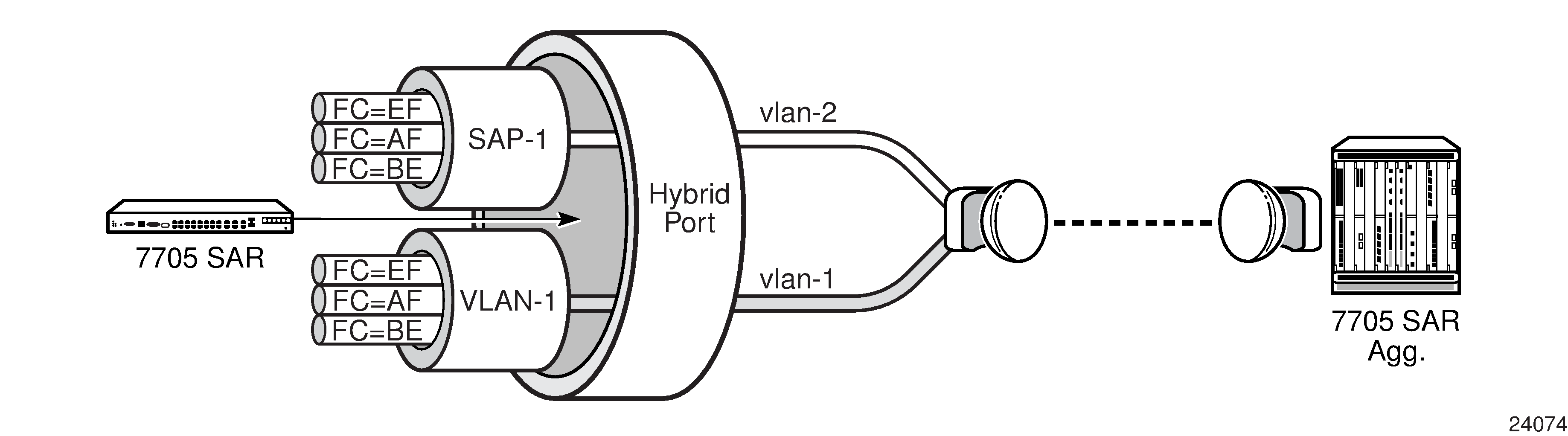
In some scenarios, combining the access and network capabilities under the same port is beneficial. A typical scenario is shown in Hybrid Port Application, where a single port hosts both access-side services and a traffic management model together with network-side IP/MPLS routing and switching capabilities simultaneously.
In this scenario, a network interface is configured to ensure connectivity between the cell site 7705 SAR and the aggregation site 7705 SAR. The network interface is used for all IP/MPLS traffic and is bound to VLAN-1. Another VLAN (VLAN-2) is configured to bind the management traffic of a microwave radio (an MPR-e) to an access-side service such as an Ethernet PW or VPLS. For security reasons, many mobile operators prefer to transport management traffic of network elements under a service construct as opposed to basic GRT-based routing. To accommodate this preference, an access-side service and a network interface can be configured to coexist on the same port when the port is configured for hybrid mode.
Configuring SCADA Bridges
Surveillance, Control, and Data Acquisition (SCADA) bridges are configured on an Integrated Services card as part of the multidrop data bridge (MDDB), pulse code modulation (PCM) multidrop bridge, and voice conference bridge (VCB) functionality. MDDB, PCM, and VCB are used to support SCADA systems on a 7705 SAR-8 Shelf V2 or 7705 SAR-18.
For information on MDDB, see Multidrop Data Bridge. For information on PCM multidrop bridge, see PCM Multidrop Bridge. For information on VCB, see Voice Conference Bridge.
A SCADA bridge can be configured after the IOM is activated (the card slot and card type are designated) and the adapter card slot is preprovisioned with the Integrated Services card mda-type.