Procedure 11-5: Establish Ethernet private line service
 Overview
This procedure provides examples for configuring Ethernet private line service using the VLNC50/52/55 circuit pack or the VLNC35 and VLNC50/52/55 circuit packs.
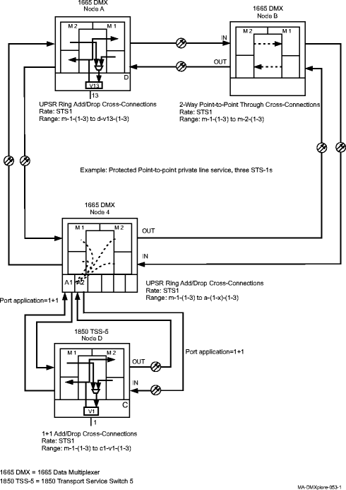
The Protected Fast Ethernet Private Line Service Example shows a protected point-to-point private line service using three STS-1 cross-connections with 1+1 line protection at the local Alcatel-Lucent 1850 TSS-5 and UPSR protection at the far end node where the service is terminated.
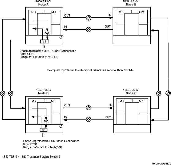
The Unprotected Fast Ethernet Private Line Service Example shows an unprotected point-to-point private line service using three STS-1 cross-connections over a UPSR network.
This procedure uses specific WaveStar® CIT menu selections to illustrate the detailed provisioning parameters.
 Before you begin
Prior to performing this procedure, refer to Before you begin and Required equipment in this chapter and you must have complete work instructions for this procedure that detail:
Steps
1 |
Use the WaveStar® CIT to log in to one of the terminating nodes, if not already performed. Reference: Procedure 14-2: Connect personal computer (PC) and establish WaveStar® CIT session | ||||||
2 |
On the System View menu, select Administration → OSI Routing Map and/or Administration → OSI Neighbor Map to retrieve a node-to-node listing of every node in the network. Important! If a drawing of the network is not provided with the work instructions, it is recommended that you draw a simple diagram of the ring (indicating node-to-node connections) and list each node's TID. This command may take several minutes to complete depending on the size of the network. Result: The OSI Routing Map or OSI Neighbor Map window opens. | ||||||
3 |
Verify that the system configuration is the same as specified on your work instructions. | ||||||
4 |
From your work instructions, determine the circuit pack, port, and cross-connections to be established at each node associated with the service to be established. | ||||||
5 |
Verify that the required VLNC35 and/or VLNC50/52/55 circuit packs/pluggable transmission modules have been installed at each Alcatel-Lucent 1850 TSS-5 providing Ethernet service. Refer to the product documentation for other systems involved in the network. For this example, refer to the Alcatel-Lucent 1665 Data Multiplexer (DMX) User Provisioning Guide, 365-372-301, to equip and provision Node A and other nodes. Reference: | ||||||
6 |
Select View → Equipment to access the required VLNC50/52/55 circuit pack and verify that the circuit pack VLAN Tagging Mode parameter value is NOTAG. If required, select Configuration → Equipment to access the VLNC50/52/55 circuit pack and provision the VLAN Tagging Mode parameter as NOTAG. Reference: Procedure 11-6: Provision VLNC50/52/55 circuit pack Ethernet-related parameters | ||||||
7 |
Determine the necessary cross-connections to be established at each terminating and non-terminating node in the network. | ||||||
8 |
Important! Note that pass-through cross-connections are used at the non-terminating nodes and add/drop cross-connections are used at terminating nodes in UPSR/SNCP networks. Reference: Procedure 11-3: Make cross-connections for Ethernet service | ||||||
9 |
Important! If establishing an STS-3/VC-4 cross-connection or a single VT1.5/VC-12/STS-1/VC-3 cross-connection to a VCG on the VLNC35 circuit pack, the Virtual Concatenation Mode parameter must be disabled. If required at each terminating node in the network, select Configuration → Equipment to access the required VCG and disable the Virtual Concatenation Mode parameter. Reference: Procedure 11-2: Provision VCG parameters | ||||||
10 |
One at a time at each terminating node in the network, select Configuration → Cross-Connections to access the Cross-Connection Wizard and provision the required cross-connections. Important! The VCG Tributary Status is enabled (default) when the cross-connection is established. Reference: Procedure 11-3: Make cross-connections for Ethernet service | ||||||
11 |
At each node, select View → Cross-Connections from the System View menu to verify that the proper cross-connections have been established. | ||||||
12 |
One at a time at each terminating node in the network, select Configuration → Equipment to access the required VCG and enable/disable the LCAS Mode parameter according to the work instructions. Reference: Procedure 11-4: Provision LCAS, add/enable/remove tributaries | ||||||
13 |
After all cross-connections are established, click on the Alarm List button on the System View window and verify no alarms are present. | ||||||
14 |
If alarms are present, look for missing or incorrect cross-connections. Reference: Alcatel-Lucent 1850 Transport Service Switch (TSS-5) Maintenance and Trouble-Clearing Guide | ||||||
15 |
At each terminating node, select Configuration → Equipment to access the required LAN port and provision the LAN port parameters according to the work instructions. Reference: Procedure 11-1: Provision Ethernet LAN port parameters If required, repeat this step to perform additional LAN port provisioning. | ||||||
16 |
Select Configuration → Equipment to access the required VCG and provision the VCG parameters according to the work instructions. Reference: Procedure 11-2: Provision VCG parameters End of steps |
Protected Fast Ethernet Private Line Service Example

Unprotected Fast Ethernet Private Line Service Example
