Segment routing with IPv6 data plane (SRv6)
SRv6 is currently supported exclusively on 7730 SXR platforms.
Segment routing steers packets by encoding the packet-processing instructions for each intermediate and destination router directly in the packet header.
The datapath pushes a list of instructions, in the form of Segment Identifiers (SIDs), onto the packet to forward the payload directly to the destination using the shortest path, or using source routing using one or more transit routers. Each router that terminates a SID in the segment list executes the instructions associated with that SID.
SRv6 is an IPv6-based segment routing approach that introduces the Segment Routing Header (SRH) as a new IPv6 extension header.
The following table highlights the differences between SR-MPLS and SRv6:
| Feature | SR-MPLS | SRv6 |
|---|---|---|
| SID encoding | 32-bit MPLS label, see Datapath programming by SID type | 128-bit IPv6 address |
| Header | MPLS label stack (no new IPv6 extension header) | Segment Routing Header (SRH) – a new IPv6 extension header |
| Forwarding plane support | No changes needed for IPv4 or IPv6 forwarding planes (uses existing MPLS forwarding). See Datapath programming by SID type | Requires forwarding plane support to parse and act on the SRH |
| Tunnel destination | Works for both IPv4 and IPv6 destinations | Works only for IPv6 destinations |
| Typical use case | Legacy MPLS networks, mixed IPv4/IPv6 environments | Pure IPv6 networks requiring segment routing capabilities |
SRv6 Segment Routing Header (SRH)
SRv6 provides more than just IPv6 transport with shortest path and source-routing capabilities; it provides a framework for IPv6 network programmability that takes advantage of the large IPv6 address space.
In shortest path routing, the destination SID is encoded in the Destination Address (DA) field of the outer IPv6 header. In source routing, the SIDs of the nodes the packet must traverse are encoded as a SID list in a Segment Routing Header (SRH), which is a new type of routing header compliant with RFC 8200. The next SID in a segment list to which the packet is to be forwarded is copied from the SRH into the DA field of the outer IPv6 header.
The following figure shows the SRv6 SRH format and fields (excerpt from RFC 8986).
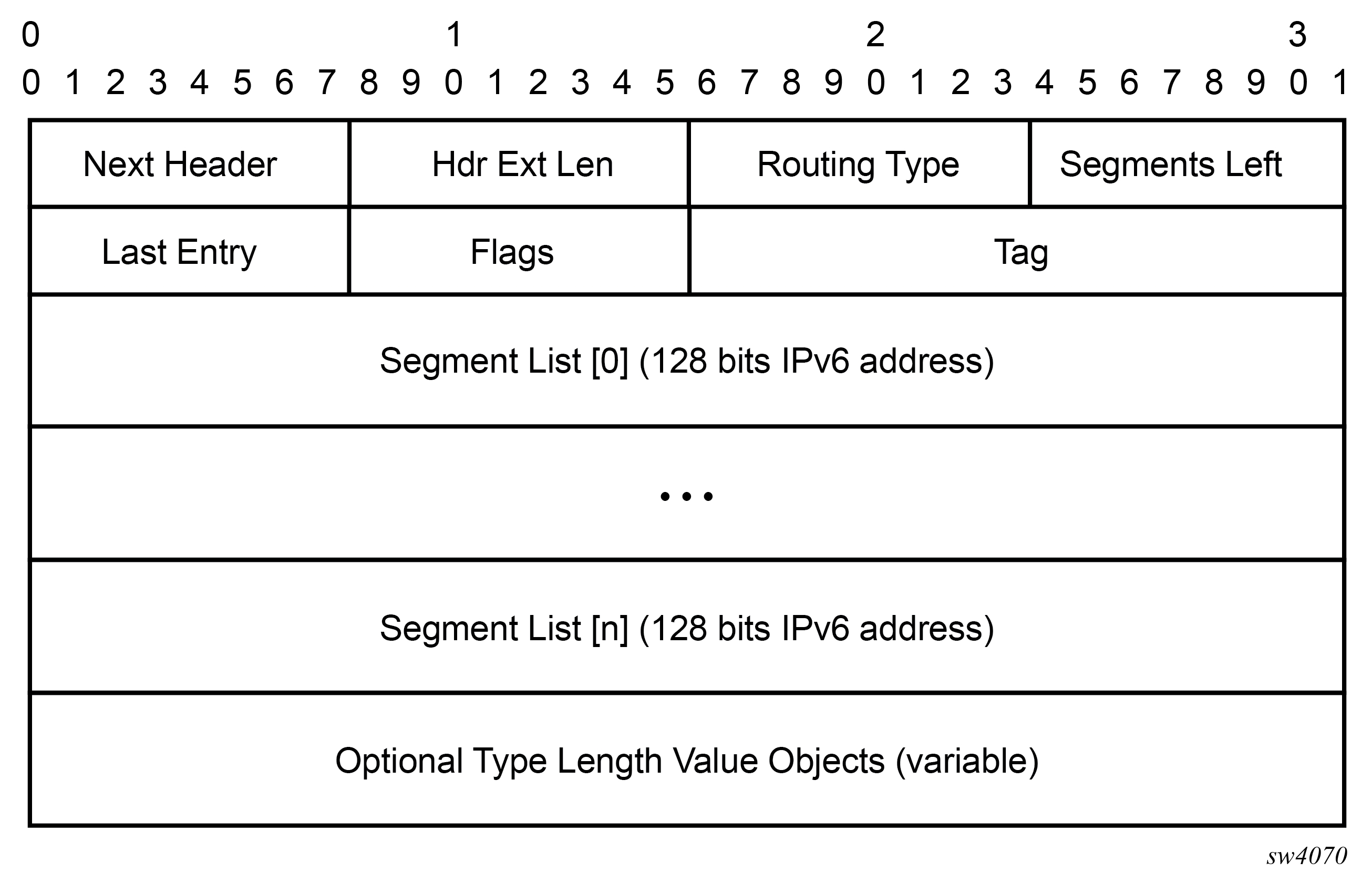
The following table lists the SRv6 field descriptions.
| Field name | Description |
|---|---|
|
Next Header |
Defined in RFC 8200, Section 4.4 |
|
Hdr Ext Len |
Defined in RFC 8200, Section 4.4 |
|
Routing Type |
Defined in RFC 8200, Section 4.4 |
|
Segments Left |
Defined in RFC 8200, Section 4.4 |
|
Last Entry |
Contains the index (zero based), in the Segment List, of the last element of the Segment List |
|
Flags |
RFC 8754, Section 8.1 creates an IANA registry for new flags to be defined. |
|
Tag |
The Tag field is used to mark a packet as part of a class or group of packets; for example, packets sharing the same set of properties. When the Tag field is not used at the source, it must be set to zero on transmission. When the Tag field is not used during SRH processing, it is ignored. The Tag field is not used when processing the SID, as defined in RFC 8754, Section 4.3.1. It may be used when processing other SIDs that are not defined in this document. The allocation and use of tags are outside the scope of this document. |
|
Segment List[0..n] |
128-bit IPv6 addresses representing the nth segment in the segment list. The Segment List is encoded starting from the last segment of the SR policy. That is, the first element of the segment list (Segment List[0]) contains the last segment of the SR policy, the second element contains the penultimate segment of the SR policy, and so on. |
|
TLV |
Type Length Value (TLV); see RFC 8754 Section 2.1, and SRv6 SID encoding. |
The following flags are defined for the SRv6 SRH Flags field.
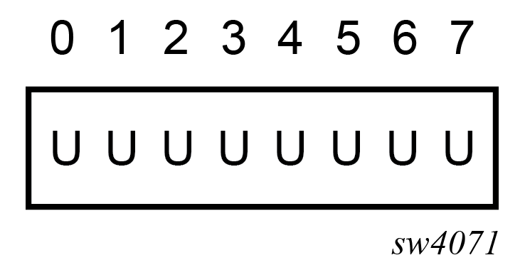
The following table lists the SRH flag descriptions.
| Flag | Description |
|---|---|
|
U |
Unused and for future use. Must be 0 on transmission and ignored on receipt. |
SRv6 SID encoding
An SRv6 SID is a routable IPv6 prefix when set as the IPv6 header DA.
IPv6 router interface addresses are not SRv6 SIDs.
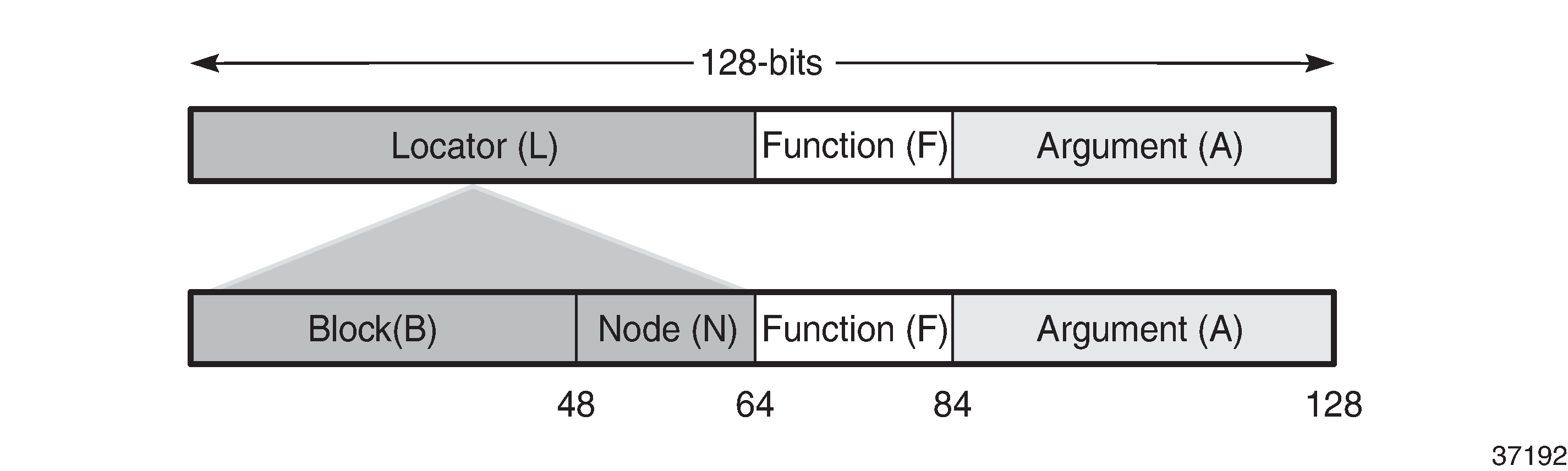
The following figure shows that the 128-bit address of an SRv6 SID is split into three constituent parts: locator, function, argument.
-
The locator is a summary IPv6 prefix for a set of SIDs instantiated on an SRv6-capable router. The locator:
-
must be explicitly configured
-
is advertised using IS-IS
-
can be associated with a topology and/or Flex-Algorithm
-
provides reachability to all SIDs originated by a router if the locator part of the SRv6 SID is routable
-
comprises the L most significant bits of the SID, with L ranging from 4 to 96 bits
-
has format B:N
-
All routers in a domain have the same block address B.
-
Each router in the domain has its own node-specific address N.
-
-
-
The function is an opaque identification of a local behavior bound to the segment, as described in RFC 8986. The following table lists the supported SRv6 endpoint behaviors.
Table 4. SRv6 endpoint behaviors supported Function name
Role or behavior
Description
End
Endpoint
Equivalent to a node SID
End.X
Endpoint with an L3 cross-connect (X-connect)
Equivalent to an adjacency SID
LAN-End.X
Endpoint with an L3 cross-connect (X-connect)
Equivalent to an adjacency SID associated with a broadcast interface
End.DT4
De-encapsulate and perform an IPv4 table lookup
-
IP-VRF table lookup: per-VRF SID for the VPN-IPv4 address family
-
Prefix lookup in the global IPv4 routing table
End.DT6
De-encapsulate and perform an IPv6 table lookup
-
IP-VRF table lookup: per-VRF SID for the VPN-IPv6 address family
-
Prefix lookup in the global IPv6 routing table
End.DT46
De-encapsulate and perform IPv4 and IPv6 table lookups
-
IP-VRF table lookup: both IPv4 and IPv6 - equivalent to per-VRF label
-
VPN-IPv4 and VPN-IPv6 routes are advertised with a single label in the same VRF
-
-
The argument, which is not a configurable field is set to all zeros.
The following figure shows an example of an SRv6 SID with the following:
-
B = 48 bits
-
N = 16 bits
-
L = B + N = 48 bits + 16 bits = 64 bits
-
F = 20 bits
-
The remaining 44 bits (A) are set to zero.
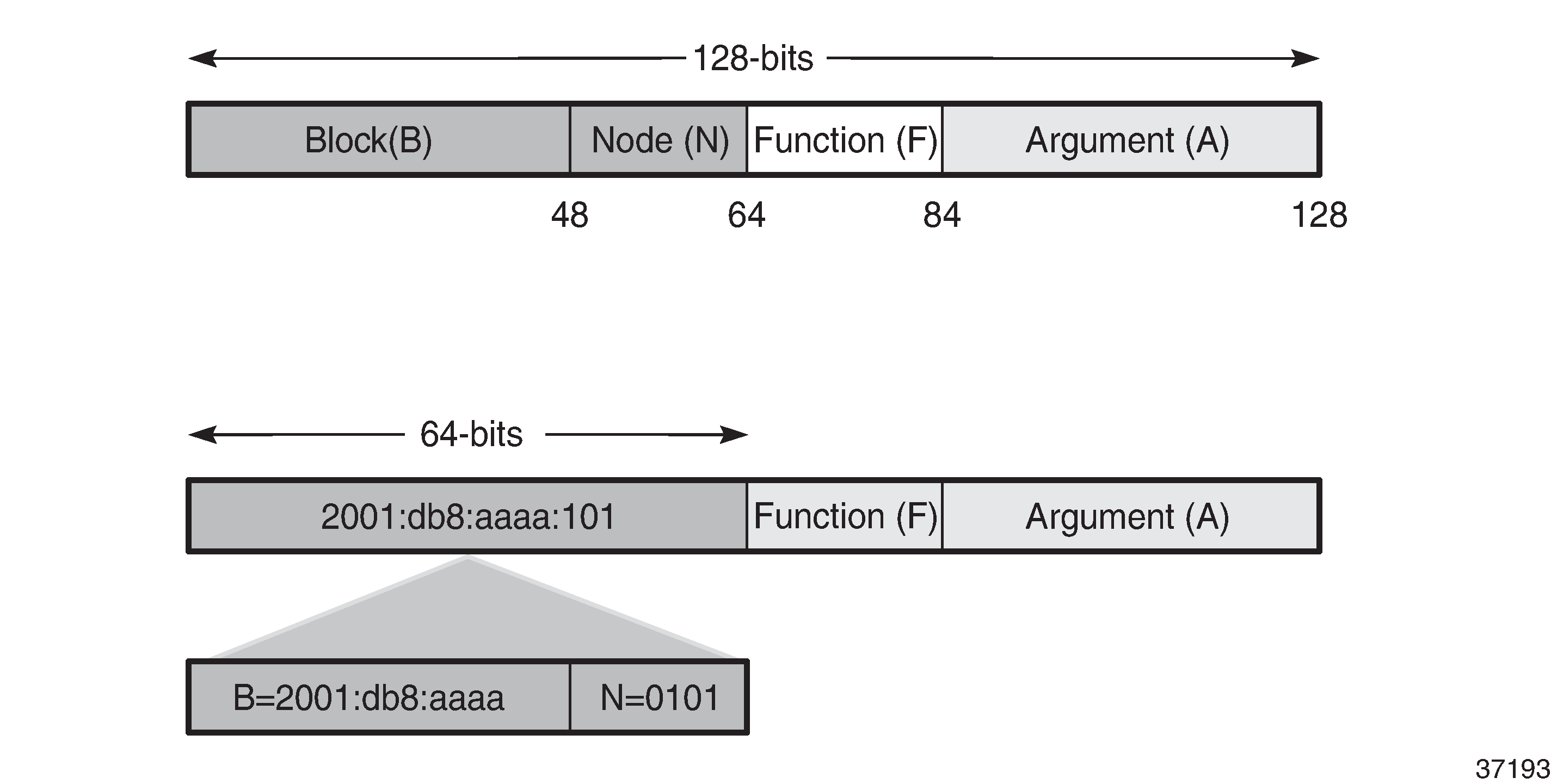
The /64 locator part for a set of routers in a routing domain consists of:
-
a common 48-bit block, for example, 2001:db8:aaaa::/48
-
a unique 16-bit node identifier allocated in the range from 0000 to ffff
Some examples:
-
locator for PE-1 = 2001:db8:aaaa:101::/64
-
locator for PE-2 = 2001:db8:aaaa:102::/64
-
locator for PE-3 = 2001:db8:aaaa:103::/64
The local router installs the locator in its IPv6 route table and FIB. The locator prefix is advertised in IS-IS in the SRv6 locator sub-TLV. Each remote router populates its route table and FIB with the locator prefixes, including the tunneled next-hop to the originating router.
The function field has a configurable length, ranging from 20 to 96 bits. By default, the function field has 20 bits. The function field is used to assign End and End.X SIDs, which are used by remote routers to create repair tunnels for remote and topology-independent loopfree-alternate (RLFA and TI-LFA) backup paths.
-
An End function is statically configured in SR Linux:
-
By default, the number of static functions is 1.
-
For example, the End function with value 1 in the 20-bit format is represented as 00001 in hexadecimal, followed by the zeros of the argument field.
-
The End SID (node SID) for PE-1 equals 2001:db8:aaaa:101:0:1000::/128, as shown in the following figure.
Figure 5. End SID for PE-1 
-
-
The End.X function can be statically configured or automatically assigned by the system.
-
In case of static configuration, the number of static functions must be increased.
-
For the function with value 2 in a function field of 20 bits, the corresponding hexadecimal pattern is 00002, followed by the zeros of the argument field.
-
The End.X SID (adjacency SID) for PE-1 equals 2001:db8:aaaa:101:0:2000::/128, as shown in the following figure.
Figure 6. End.X SID for PE-1 
-
SRv6 node types
Different SR node types are defined: source node, transit node, and segment endpoint node.
The following figure shows the SR node types for an SRv6 packet flow from R0 to R5 via hops R1, R3, and R5.
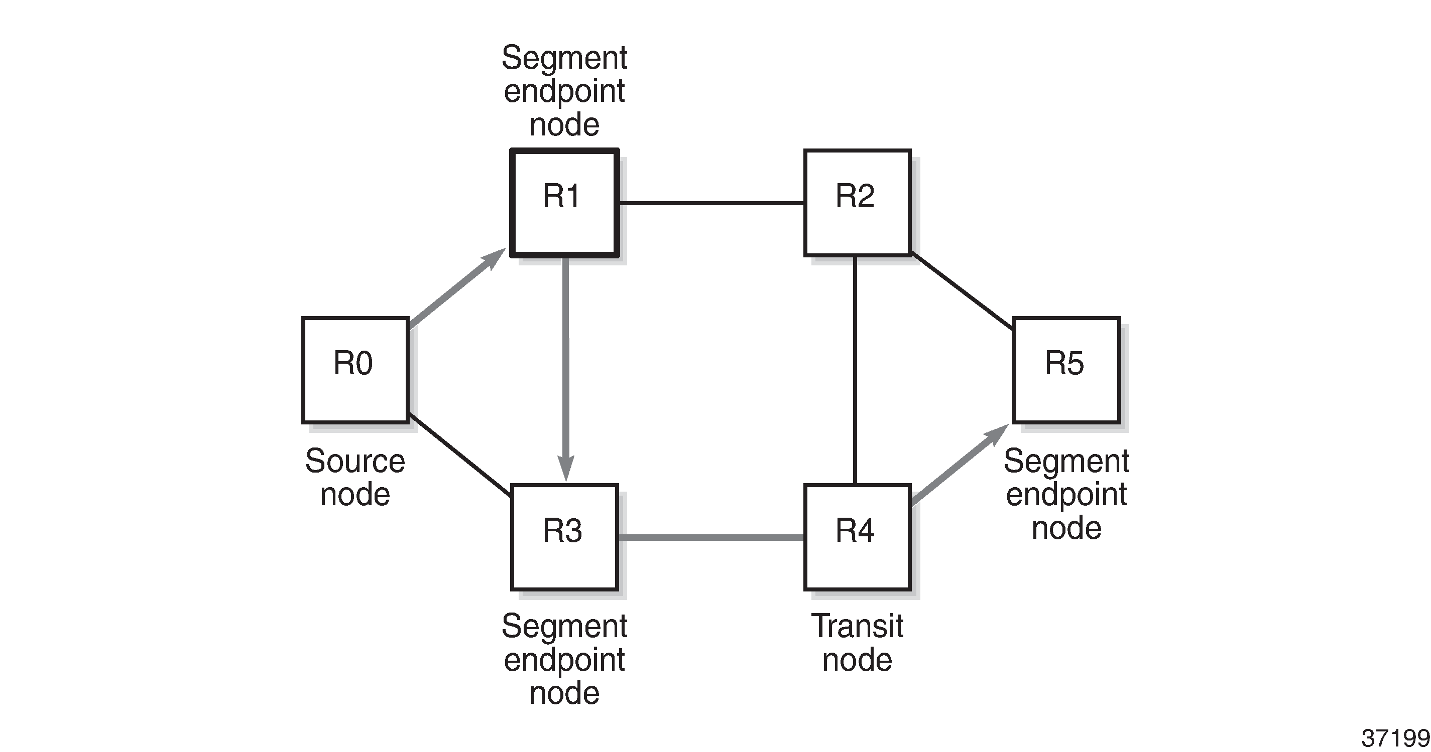
The intermediate hops R1, R3, and R5 are programmed in the segment list of the SRH.
The SRv6 node types defined in RFC 8754 are:
-
SR source node
-
Any node that originates an IPv6 packet with a segment (that is, an SRv6 SID) in the DA field of the IPv6 header.
-
The IPv6 packet leaving the SR source node may or may not contain an SRH. This includes either:
-
a host originating an IPv6 packet
-
an SR domain ingress router encapsulating a received packet in an outer IPv6 header, followed by an optional SRH
-
-
In this example, R0 acts as an SR source node and includes an SRH containing a segment list.
-
-
SR transit node
-
Any node forwarding an IPv6 packet where the DA of the packet is not locally configured as a segment or a local interface. A transit node does not need to be capable of processing a segment or SRH.
-
In this example, R4 acts as an SR transit node. It forwards the SRv6 packet without processing the SRH.
-
-
SR segment endpoint node
-
Any node receiving an IPv6 packet where the DA of that packet is locally configured as a segment or local interface.
-
In this example, R1, R3, and R5 are SR segment endpoint nodes. These nodes interrogate the SRH as part of packet processing.
-
The following figure shows the data forwarding of SRv6 encapsulated packets using SRv6 SIDs at R0 and R1.
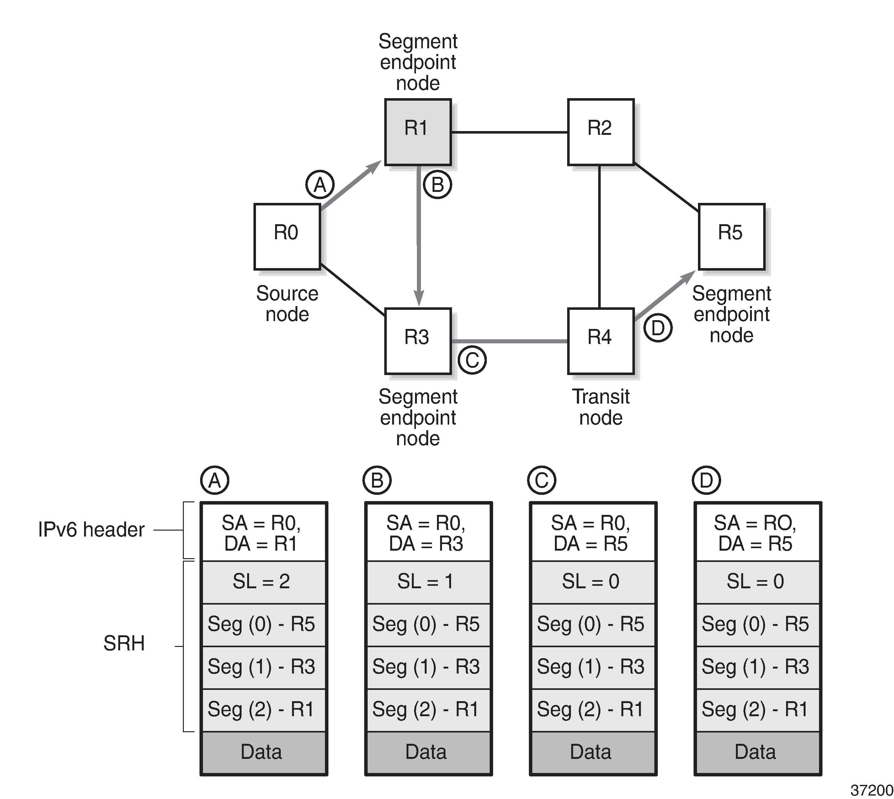
Source node R0 tunnels an SRv6 packet to destination R5, segment (0), in the SRH.
-
The segment list contains SRv6 SIDs associated with each hop, such as the End SID. The first segment endpoint is the last segment in the list, segment (2) in the example. The Segments Left (SL) field is set to a value matching the highest segment list number (2).
-
SRH is only used by routers where the DA is equal to a local address. The IPv6 source address is set to the local IPv6 address of R0. The IPv6 DA in the IPv6 header is set to the segment list entry indexed in the SL field; in this case, R1.
-
The packet is forwarded to R1.
At R1, the incoming packet has the IPv6 DA matching R1.
-
R1 removes the IPv6 header and processes the SRH. The SL is decremented to SL 1, which corresponds to segment (1) = R3.
-
R1 adds an IPv6 header with DA equal to the SID for R3.
-
R1 forwards the packet to R3.
At R3, the incoming packet has the IPv6 DA matching R3.
-
R3 removes the IPv6 header and processes the SRH. The SL is decremented to SL 0, which corresponds to segment (0) = R5.
-
R3 adds an IPv6 header with DA equal to the SID for R5.
-
R3 forwards the packet to R5.
At R4, the incoming packet has the IPv6 DA matching R5, so the packet is forwarded to R5 without processing the SRH header and without changing the IPv6 DA.
At R5, the incoming packet has the IPv6 DA matching R5, so the IPv6 header is removed and the SRH header is processed. The SL value 0 cannot be decreased anymore, so R5 removes the SRH and the packet is sent for further processing, for example, to a particular IP-VRF.
The IPv6 SID at segment (0) may contain an opaque behavior value (function) that indicates to the destination node that further processing is required, such as a IP-VRF table lookup.
SRH processing modes
SR Linux supports the following SRH processing modes at the end of the SRv6 tunnel:
-
Ultimate SRH Pop (USP), where the ultimate SR segment endpoint node processes and removes the SRH
-
Penultimate SRH Pop (PSP), where the penultimate SR segment endpoint node processes and removes the SRH
- Ultimate Segment Decapsulation (USD), where the ultimate SR segment endpoint decapsulates the entire outer IPv6 header and all extension headers (including SRH) at the final node to forward the inner payload.
SRv6 Micro-SID (uSID)
SR Linux supports micro-segment SRv6. The system supports concurrent operation in both modes (regular and micro) on the same platform, but requires that the SIDs for each type come from different SID blocks.
Micro-segment SRv6 provides the same functionality as regular SRv6 but uses 16-bit SIDs, known as micro-SIDs, instead of 128-bit SIDs.
Micro-segment (uSID) encodes multiple short instructions (micro-SIDs) into a single 128-bit IPv6 address container called a uSID Carrier.
Micro-SIDs follow the same general structure as regular SIDs (LOCATOR:FUNCTION:ARGUMENT), but differ in key aspects described in the following table.
| Features | full-segment (SID) | micro-segment (uSID) |
|---|---|---|
| Size per ID | 128 bits | 16 bits |
| Encapsulation | One SID per list entry | Multiple IDs per 128-bit carrier |
In regular SRv6, identifiers are assigned to nodes and form, together with the SID block, the LOCATOR part of any SID. SIDs are assigned per node and associated with a specific behavior (or function), resulting in the LOCATOR:FUNCTION structure.
Micro-segment SRv6 introduces a specific function (uN) which acts both as a locator (when combined with the block) and as a function (corresponding to END in regular SRv6), but without using any FUNCTION bits. In other words, the LOCATOR and END constructs of regular SRv6 correspond to a unique construct in micro-segment SRv6: <block><uN>.
Micro-segment SRv6 allows micro-SIDs to be compressed. Compression consists of coalescing several micro-SIDs into a 128-bit structure called a container.
The following figure shows three micro-SIDs, each identifying a different node in a network. The figure shows the result of compressing these three micro-SIDs in a container. Compression is possible because all micro-SIDs belong to the same block.
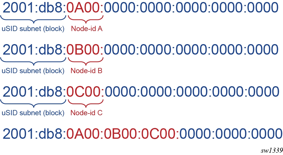
A container can be placed in the DA field of an IPv6 header and in a segment of the segment list of an SRH.
Compression allows the router to build longer paths with less overhead than with regular SRv6. However, it leads to specific datapath behaviors.
Micro-segment SRv6 introduces specific micro-segment SRv6 functions that correspond to functions defined for regular SRv6 (see Micro-segment SRv6 and BGP service control plane extensions).
In general, any SR Linux capability that applies to regular SRv6 also applies to micro-segment SRv6. In the documentation, only the differences are highlighted and commonalities are not repeated using micro-segment SRv6 specific terminology.
Configuring the SRv6 locator and SIDs
An SRv6 SID is a 128-bit IPv6 address which follows the structure defined by RFC 8986:
SRv6 SID={LOCATOR:FUNCTION:ARGUMENT}
You must configure the main SRv6 subnet on the SRv6-enabled router.
The SRv6 locator is an IPv6 subnet (prefix and length) that provides reachability to all SIDs originated by this router using longest-prefix-match. The locator prefix, encoded in the LOCATOR field of the SRv6 SID, can be 64 or 96 bits long.The locator is subdivided into a SID block and a node ID.
For example, locator 3FFE:0:0:A1::/64 includes a SID block of 3FFE:0 and a node ID of 0:A1.
All nodes in an SRv6 domain must use locators and SIDs from the same SID block. In the previous example, the SID block is subnet 3FFE:0::/32.
SRv6 locators are created globally under system.srv6.locator and referenced per network-instance via locator-name in network-instance.segment-routing.srv6.instance.locator context.
One locator is required for algorithm 0 and for each IGP flexible algorithm (128-255). Multiple IGP instances can share the same locator for the same algorithm number.
The locator prefix (for example, 3FFE:0:0:A1::/64) is advertised in the SRv6 Locator TLV in IS-IS for both algorithm 0 and any configured flexible algorithm number, as defined in draft-ietf-lsr-isis-srv6-extensions.
It is also advertised as a prefix in the IP Reachability TLV (IS-IS TLV 236) for algorithm 0, allowing routers without SRv6 support to route packets to the next hop of the locator and ultimately to the destination node.
The FUNCTION field is user-configurable.
The ARGUMENT field is set to all zeros and cannot be configured. The ARGUMENT length must be signaled as zero in IS-IS End and End.X SIDs and in BGP service SIDs.
The combined length of LOCATOR and FUNCTION must not exceed 128. Within algorithm 0 and each IGP flexible algorithm, the locator function (FUNCTION field) assigns values to the End SID and End.X SID, which correspond to the node SID and the adjacency or adjacency SET SID.
The locator function also assigns values to the service SIDs owned by this node and advertised in the BGP control plane (End.DT4, End.DT6, End.DT46, and End.DX2).
The FUNCTION field can be divided into static and dynamic subranges. Use the static subrange to manually assign an SRv6 SID to a node, local adjacency, or service. IS-IS and BGP use the dynamic subrange to assign a SID to a local adjacency or service. The SID for an adjacency to an IS-IS neighbor over a broadcast interface (LAN End.X) is always dynamically assigned and cannot be configured.
Configuring the SRv6 locator
In the following configuration example, the SRv6 locator srl_loc1 is defined with a /48 prefix 2001:db8:100::/48 (block-length 48) and a 16-bit function field (function-length 16) using algorithm 0, allowing up to 1024 static function entries.
--{ + candidate shared default }--[  ]--
# info with-context system srv6 locator srl_loc1
    system {
        srv6 {
            default-source-address 2001:db8:100::1
            source-address 2001:db8:100::1 {
            }
            locator srl_loc1 {
                full-segment {
                    block-length 48
                    function-length 16
                    algorithm 0
                    prefix {
                        ip-prefix 2001:db8:100::/48
                    }
                    static-function {
                        max-entries 1024
                    }
                }
            }
        }
    }
Configuring the SID
The SRv6 instances are configured per network-instance under network-instance.segment-routing.srv6.instance, with id in the range 1-2.
In the following configuration example, two static SIDs are provisioned in network instance : an End SID with function 100 (SRH mode psp) and an End-X SID with function 200 (SRH mode psp, protected, bound to sub-interface ethernet-1/1.0).
--{ + candidate shared default }--[  ]--
# info with-context network-instance default segment-routing srv6 instance 1
    network-instance default {
        segment-routing {
            srv6 {
                instance 1 {
                    locator srl_loc1 {
                        full-segment {
                            function {
                                end 100 {
                                    srh-mode psp
                                }
                                end-x 200 {
                                    srh-mode psp
                                    protection protected
                                    subinterface-name ethernet-1/1.0
                                }
                            }
                        }
                    }
                }
            }
        }
    }
Displaying regular SRv6 locator local SIDs
You can use a show command to display information about regular SRv6 locator local SIDs.
--{ + running }--[  ]--
# show system srv6 full-segment-locator local-sids
==========================================================================================

SRv6 End SIDS on Net-Inst: "default" SRv6 Inst: "1"

------------------------------------------------------------------------------------------

+---------------------------------------------------------------------------+

| Locator Name                       Function     SID                       |

|                                    Value                                  |

+===========================================================================+

| A1                                 201          2222:2:2:2:c9::           |

+--------------------------------------------------------------------------+

No. of end sids: 1

==========================================================================================

SRv6 Network Instance SIDS

S - Static Sids, D - Dynamic Sids

------------------------------------------------------------------------------------------

+----------------------------------------------------------------------------------------+

| Network Instance                   Inst    Locator Name                       Function     Function     S     SID                       |

|                                                                               Type         Value        or                              |

|                                                                                                         D                               |

+========================================================================================+

| 1                                  1       A1                                 End-Dt46     101          S     2222:2:2:2:65::           |

| 10                                 1       A1                                 End-Dt46     110          S     2222:2:2:2:6e::           |

| 2                                  1       A1                                 End-Dt46     102          S     2222:2:2:2:66::           |

| 3                                  1       A1                                 End-Dt46     103          S     2222:2:2:2:67::           |

| 4                                  1       A1                                 End-Dt46     104          S     2222:2:2:2:68::           |

| 5                                  1       A1                                 End-Dt46     105          S     2222:2:2:2:69::           |

| 6                                  1       A1                                 End-Dt46     106          S     2222:2:2:2:6a::           |

| 7                                  1       A1                                 End-Dt46     107          S     2222:2:2:2:6b::           |

| 8                                  1       A1                                 End-Dt46     108          S     2222:2:2:2:6c::           |

| 9                                  1       A1                                 End-Dt46     109          S     2222:2:2:2:6d::           |

+----------------------------------------------------------------------------------------+

No. of network-instance sids: 10

==========================================================================================
Session has been idle, will logout in 300 seconds
--{ + running }--[  ]--
Configuring the micro-segment locator and SIDs
SRv6 micro-segments are defined at the global level under system.srv6.locator, and each locator also has its own micro-segment definitions and SID functions under both system.srv6.locator and the per-instance hierarchy network-instance.segment-routing.srv6.instance.
- The user configures SIDs that are specific to micro-segment SRv6 (uA, uDT4, uDT6, uDT46).
- The configured value only needs to be unique on the system and not network wide.
- The resulting SID value is derived from the local range.
- Although the uN function is equivalent to the regular SRv6 END function, it is not configurable under the base instance because it is configured in the micro-segment-locator context.
| Parameters | Description |
|---|---|
| block-length | Operates the same as the standard SRv6 block-length version and the value must be the same on every platform network wide. |
| gib-size | Defines the maximum number of unique micro-segment locators that
can be configured network wide. The value must be the same on every
platform, network wide. This command splits in two the total number
of values that can be encoded in 16 bits. A 16-bit field allows
values in the range 0x0000 to 0xFFFF. Configuring 16 (default value)
for the global-sid-entries value splits that range into the
following:
|
| sid-length | Defines the length of micro-SIDs. The only supported value is 16 (bits). |
| Parameters | Description |
|---|---|
| locator-name | SRv6 locator name |
| algorithm | IGP flexible algorithm ID |
| block | Reference to a pre-defined micro-SID block under system
srv6 micro-segment block |
| srh-mode | Segment Routing Header (SRH) mode for uN |
| value | SRv6 uN function value. |
| Parameters | Description |
|---|---|
| id | SRv6 instance ID |
| locator-name | SRv6 locator name, referencing a system locator. |
| protection | Adjacency protection for automatic uA SID function |
| srh-mode | SRH mode for automatically allocated uA SIDs. |
| value | SRv6 SID function value for uA |
| value | SRv6 SID function value for uDT4 |
| value | SRv6 SID function value for uDT6 |
| value | SRv6 SID function value for uDT46 |
| value | SRv6 SID function value for uDX2 |
Configuring a global SRv6 micro-segment block
In the following configuration, a global SRv6 micro-segment block (srl_blk) is defined.
--{ + candidate shared default }--[  ]--
# info with-context system srv6 micro-segment
    system {
        srv6 {
            micro-segment {
                block-length 32
                gib-size 48
                sid-length 16
                block srl_blk {
                    prefix {
                        ip-prefix 2001:db9::/32
                    }
                    static-function {
                        max-entries 256
                    }
                }
            }
        }
    }
Configuring an SRv6 locator and binding it to the micro-segment block
In the following configuration example, an SRv6 locator (srl_loc_microsegment) is defined and attached to the pre-defined micro-segment block (srl_blk).
--{ + candidate shared default }--[  ]--
# info with-context system srv6 locator srl_loc_microsegment
    system {
        srv6 {
            locator srl_loc_microsegment {
                micro-segment {
                    block srl_blk
                    algorithm 0
                    un {
                        srh-mode psp
                        value 1
                    }
                }
            }
        }
    }
Configuring micro-segment SID functions
In the following configuration example, the locator (srl_loc_microsegment) is referenced and micro-segment SID functions are configured within a network instance SRv6 instance.
--{ + candidate shared default }--[  ]--
# info with-context network-instance default segment-routing srv6 instance 1
    network-instance default {
        segment-routing {
            srv6 {
                instance 1 {
                    locator srl_loc_microsegment {
                        micro-segment {
                            function {
                                ua 10 {
                                    srh-mode psp
                                    protection protected
                                    subinterface-name ethernet-1/1.0
                                }
                                ua 100 {
                                    srh-mode psp
                                    protection protected
                                    subinterface-name ethernet-1/1.0
                                }
                            }
                        }
                    }
                }
            }
        }
    }
Displaying micro-segment SRv6 locator local SIDs
You can use a show command to display information about micro-segment SRv6 locator local SIDs.
--{ + running }--[  ]--
# show system srv6 micro-segment-locator local-sids
=========================================================================================

SRv6 un SIDS

------------------------------------------------------------------------------------------

+---------------------------------------------------------------------------+

| Locator Name                       Function     SID                       |

|                                    Value                                  |

+===========================================================================+

| A1                                 1            3336:1:1::                |

| A2                                 2            3336:2:2::                |

| A3                                 3            3336:3:3::                |

| A4                                 4            3336:4:4::                |

| A5                                 5            3336:5:5::                |

| A6                                 6            3336:6:6::                |

| C1micro                            3            1111:1:3::                |

+---------------------------------------------------------------------------+

No. of un sids: 7

==========================================================================================

SRv6 Network Instance SIDS

S - Static Sids, D - Dynamic Sids

------------------------------------------------------------------------------------------

+-----------------------------------------------------------------------------------------+

| Network Instance                   Inst    Locator Name                       Function     Function     Oper         S     SID                       |

|                                                                               Type         Value        Function     or                              |

|                                                                                                         Value        D                               |

+=========================================================================================+

| default                            1       A1                                 udt46        301          16684        S     3336:1:1:412c::           |

| default                            1       A2                                 udt46        302          16685        S     3336:2:2:412d::           |

| default                            1       A3                                 udt46        303          16686        S     3336:3:3:412e::           |

| default                            1       A4                                 udt46        304          16687        S     3336:4:4:412f::           |

| default                            1       A5                                 udt46        305          16688        S     3336:5:5:4130::           |

| default                            1       A6                                 udt46        306          16689        S     3336:6:6:4131::           |

| default                            1       C1micro                            udt46        101          16484        S     1111:1:3:4064::           |

+-----------------------------------------------------------------------------------------+

No. of network-instance sids: 7

==========================================================================================
Assigning loopback interface addresses from an SRv6 locator subnet
SR Linux supports assigning IPv6 addresses to a system (for example, system0) or a loopback interface (for example, lo0) drawn from a classic or micro-segment SRv6 locator prefix subnet.
To enable this feature, you must configure an IPv6 address for the system or loopback interface from a classic or a micro-segment locator by setting bits in the least significant octet of the locator, as described in Assigning an IPv6 address from a classic SRv6 locator and Assigning an IPv6 address from a micro-segment SRv6 locator. Only a /128 subnet mask is allowed for IPv6 addresses. Addresses from a flex-algo locator are not allowed.
A number of checks are performed in CPM to enforce the correct setting of the prefix bits and mask, and to verify the overlap with a locator subnet. See CPM support with classic SRv6 locator and CPM support with micro-segment SRv6 locator for more information.
A system or loopback interface configured to use an IPv6 address from an algorithm 0 locator address space behaves like any other system or loopback interface. It can be injected into IGP or BGP routing protocols, as well as into a VRF. Its address can be used as the source or destination address for control-plane protocol and OAM packets.
network.instance.Assigning an IPv6 address from a classic SRv6 locator
When assigning an IPv6 address from a classic SRv6 locator, the feature reserves the least significant octet of the locator subnet for the IPv6 address of the system (for example, system0) and loopback interfaces (for example, lo0). This is the main subnet of the locator with bits to the right of the node ID set to zero, except for the interface bits.
The following is an example of the address assignment.
- locator subnet: fc01:1:0:105::/64
- locator subnet identifier: fc01:1:0:105:0:0:0:0
- system/loopback interface addresses allowed are: fc01:1:0:105:0:0:0:00[01-FF]/128
This feature supports only a/128 mask value. A maximum of 255 addresses can be allocated from the last octet of the locator. A value of zero for that octet represents the identifier of the entire subnet and is not allocatable.
CPM support with classic SRv6 locator
The following checks are performed in the CPM when assigning an IPv6 address from an SRv6 locator subnet. If any of the checks fail, the configuration fails.
-
An address of the system interface or a loopback interface can only be drawn from the subnet of a classic SRv6 locator prefix assigned to algorithm 0.
-
An address of the system interface or a loopback interface can only be drawn from a classic SRv6 locator prefix subnet that satisfies the following condition:
{Prefix-length + function-length} < 120 bits -
An address of the system interface or a loopback interface must have all bits to the right of the classic SRv6 locator’s node ID field set to zero, except for the bits of the least significant octet.
-
Creating a new locator or changing the prefix, function-length, or prefix-length of a configured locator is not allowed if an address from the locator prefix subnet is already assigned to the system or a loopback interface. Users must first delete the corresponding addresses from the system interface or loopback interfaces.
Assigning an IPv6 address from a micro-segment SRv6 locator
When assigning an IPv6 address from a micro-segment SRv6 locator, the feature reserves the least significant octet of the micro-segment locator subnet for the IPv6 address of system and loopback interfaces. This is the main subnet of the locator, with the bits to the right of the uN set to zero, except for the interface bits.
The following is an example of the address assignment.
- locator subnet: fc00:0:105::/48
- locator subnet identifier: fc00:0:105:0:0:0:0:0
- system/loopback interface addresses allowed are: fc00:0:105:0:0:0:0:00[01-FF]/128
This feature supports only a/128 mask value. A maximum of 255 addresses can be allocated from the last octet of the locator. A value of zero for that octet represents the identifier of the entire subnet and is not allocatable.
CPM support with micro-segment SRv6 locator
The following checks are performed in CPM when assigning an IPv6 address from a micro-segment SRv6 locator subnet. If any of the checks fail, the configuration fails.
- An address of the system interface or a loopback interface can only be drawn from the subnet of a micro-segment SRv6 locator prefix assigned to algorithm 0.
- An address of the system interface or a loopback interface can only be drawn from a
micro-segment SRv6 locator prefix subnet that satisfies the following
condition:{Block-length + sid-length(uN) + sid-length(uA or uDT)} < 120 bits
- An address of the system interface or a loopback interface must have all bits to the right of the micro-segment SRv6 locator’s uN field set to zero, except for bits of the least significant octet.
-
Creating a new locator, changing the uN value of a configured locator, or changing the block length of a configured locator are not allowed if an address from the locator prefix subnet is already assigned to the system or a loopback interface. You must first delete the corresponding addresses from the system interface or loopback interfaces.
Datapath support
The following procedures are supported in the datapath:
- When the user configures an IPv6 address for a system interface or a loopback
interface, and that address is drawn from the subnet of a locally configured
locator, the CPM adds the /128 prefix into the route table and into the FIB.
- A packet matching the more specific route in the FIB for the interface is extracted to the CPM for local interface processing.
- A packet matching the less specific locator route of the locator in the FIB undergoes SRv6 tunnel termination processing, as usual.
-
Ingress PE and transit P routers forward packets destined for this system or the loopback interface using either the more-specific interface route, if advertised in IGP or BGP by the owner router, or the less-specific locator route from which the interface address is derived.
- A packet destined for the system or a loopback interface whose IPv6 address is drawn from a local locator prefix subnet can be received with an SRH in its encapsulation. An example use case of a packet received from a transit router that forwarded it over the remote LFA or TI-LFA repair tunnel of the corresponding less-specific locator route when the repair tunnel SIDs are in USP SRH mode.
IS-IS control plane extensions
The IS-IS control plane extensions for SRv6 are defined in draft-ietf-lsr-isis-srv6-extensions.
The IS-IS control plane advertises the SRv6 capabilities sub-TLV and the SRv6 Locator TLV. The latter includes the End function sub-TLV (equivalent to the prefix SID sub-TLV in SR-MPLS). IS-IS also advertises the End.X function sub-TLV (equivalent to the adjacency SID sub-TLV for a P2P link and a LAN in SR-MPLS) in the Extended IS Reachability TLV (top-level link TLV).
The weight fields in the End.X and LAN End.X sub-TLVs are not populated on transmit and are ignored on receipt of the link TLV.
The following table describes the supported IS-IS SRv6 TLVs in SR Linux.
| SRv6 TLV/sub-TLV | Codepoint | IS-IS context TLV | Description | SR Linux support |
|---|---|---|---|---|
|
SRv6 Capabilities sub-TLV |
25 |
Router CAPABILITY TLV (242) |
Indicates SRv6 support |
Yes |
|
SR-Algorithm sub-TLV |
19 |
Router CAPABILITY TLV (242) |
Indicates base algorithm 0 and Flex-Algo 128-255 support |
Yes |
|
Maximum Segments Left MSD Type sub-TLV |
41 |
Router CAPABILITY TLV (242) |
Indicates how deep a node terminating current segment can process Segments Left field of the SRH to move the next SID to outer IPv6 header DA field |
Yes Advertised value = 7 SIDs Received TLV is displayed in the LSDB but is not used for any purpose |
|
Maximum End Pop MSD Type sub-TLV |
42 |
Router CAPABILITY TLV (242) |
Maximum number of SIDs in a SRH when a node removes the SRH (Penultimate Segment Pop (PSP) or Ultimate Segment Pop (USP) modes of SRH) |
Yes Advertised value = 7 SIDs Received TLV is displayed in the LSDB but is not used for any purpose |
|
Maximum H.Encaps MSD type sub-TLV |
44 |
Router CAPABILITY TLV (242) |
Indicates the maximum number of SIDs in an SRH that a router can push when forwarding an IP or L2 packet over a SRv6 policy |
Yes Advertised value = 7 SIDs Received TLV is displayed in the LSDB but is not used for any purpose |
|
Maximum End D MSD Type Sub-TLV |
45 |
Router CAPABILITY TLV (242) |
The maximum number of SIDs in an SRH when a node removes the SRH and performs the End.DX2/4/6 or End.DT4/6 function (USP mode of SRH) |
Yes Advertised value = 7 SIDs Received TLV is displayed in the LSDB but is not used for any purpose |
|
SRv6 Locator TLV |
27 |
Is a Top-level IS-IS TLV |
Advertises the locator prefix configured on this node to terminate SIDs in algorithm 0 and flex-algo 128-255 |
Yes |
|
SRv6 End SID sub-TLV |
5 |
SRv6 Locator TLV |
Advertises the SID for the endpoint or End function (equivalent to the prefix SID sub-TLV in SR-MPLS) |
Yes |
|
Prefix Attribute Flags Sub-TLV |
4 |
SRv6 Locator TLV (Also in IP Reach TLV 236) |
Provides attributes of a prefix leaked between IS-IS levels |
Yes |
|
SRv6 End.X SID sub-TLV |
43 |
Top-level Extended IS reachability TLV (22) |
Advertises the SID for the adjacency over a P2P link (equivalent to the adjacency SID sub-TLV for P2P link in SR-MPLS) |
Yes |
|
SRv6 LAN End.X SID sub-TLV |
44 |
Top-level Extended IS reachability TLV (22) |
Advertises the SID for the adjacency over a LAN (equivalent to the adjacency SID sub-TLV for LAN in SR-MPLS) |
Yes |
|
SRv6 SID Structure Sub-Sub-TLV |
1 |
SRv6 End SID Sub-TLV SRv6 End.X SID Sub-TLV SRv6 LAN End.X SID Sub-TLV |
Provides the length of each field (Block, Locator, Function, and Argument) of the SRv6 SID that it is advertised with |
No SR Linux does not advertise this sub-sub-TLV. If received from other vendor's implementation, it is not displayed in the Link-State database and is also not propagated with the locator TLV |
When both SR-MPLS and SRv6 are enabled on the same IS-IS instance, an MPLS node SID cannot be configured for a prefix of the locator or an End SID. This is because the SRv6 locator subnet cannot be added to a network interface and an MPLS node SID is configurable against a network interface only.
However, both the SRv6 locator tunnel and the SR-MPLS tunnel are programmed if IS-IS receives a /128 prefix that has both a locator TLV and a prefix SID TLV (with the node flag enabled) from a third-party router implementation. If the prefix SID is for a subnet larger than /128, only the SRv6 locator tunnel is programmed and the SR-MPLS tunnel is not.
Each function encoded in an SRv6 SID has its own endpoint behavior codepoint as listed in SRv6 SID function endpoint behavior codepoints.
SR Linux advertises service SID functions in the BGP control plane only as described in BGP service control plane extensions.
For the SRH processing and removal at the SID termination, the following modes of operation are associated with the termination of the End or End.X SID. These modes are sometimes referred to as SID flavors and IS-IS assigns a unique codepoint for each mode of the End or End.X SID of a given adjacency.
-
Basic or unflavored SRH mode
The router that terminates an End or End.X SID and the Segments-Left field in the received packet is 0 before decrementing, keeps the SRH in the packet, and processes the packet identified by the next-header in the SRH. Typically, the next-header indicates another SRH and the packet is then forwarded based on the lookup of that next-SID; SR Linux does not support this mode.
-
Ultimate Segment Pop (USP) SRH mode
The egress PE terminates the last segment in the outer IPv6 header, removes the SRH and processes the inner service or control plane packet as indicated by the SRH next-header field. SR Linux supports this mode.
-
Penultimate Segment Pop (PSP) SRH mode
The router that terminates the End or End.X segment before the last in the segment list, meaning the Segments-Left field before decrementing has a value of 1, removes the SRH on behalf of the egress PE. SR Linux supports this mode.
-
Ultimate Segment Decapsulation (USD) mode (psp-usd, usp-usd, and psp-usp-usd flavors)
This is a variant of the USP mode in which the node removes the outer IPv6 header and associated SRH and moves directly to process the inner IPv6 packet as indicated by the SRH next-header field. This mode is used to terminate a TI-LFA or a Remote LFA repair tunnel originated with the H.Encaps.Red encapsulation.
An SRv6 ingress PE or transit P router normally uses the H.Insert.Red behavior to build an LFA (remote LFA or a TI-LFA) repair tunnel. This inserts a dedicated SRH to carry the additional node and adjacency SIDs of the repair tunnel. SR Linux supports originating and terminating repair tunnels using H.Insert.Red behavior.
Some third-party implementations use the H.Encaps.Red behavior, which inserts a dedicated outer IPv6 header and SRH to carry the additional SIDs of the LFA repair tunnel. While SR Linux does not support originating an LFA repair tunnel with the H.Encaps.Red behavior, it does support terminating the repair tunnel.
To allow third-party implementations to activate the H.Encaps.Red repair tunnel, IS-IS in SR Linux can signal support for the USD mode of the outer IPv6 header and SRH processing with End and End.X SIDs in classic SRv6, and with uN and uA in micro-segment SRv6.
You can configure the advertisement of the psp-usd, usp-usd, or psp-usp-usd flavor of the USD mode for each configured and auto-allocated node SID or adjacency SID. The psp-usp-usd behavior is similar to the psp-usd behavior because the datapath in SR Linux always performs the USP SRH mode when Segments-Left = 0 on a received SRv6 packet.
| SID function endpoint behavior | Codepoint (per RFC 8986) | SID type: End.SID | SID type: End.X SID | SID type: LAN End.X SID | Advertising protocol | Supported |
|---|---|---|---|---|---|---|
|
End (PSP, USP, USD) |
1-4, 28-31 |
Yes |
No |
No |
IS-IS |
Yes IS-IS only (PSP value = 2, USP value = 3) (PSP&USD value = 29, USP&USD value = 30) (PSP&USP&USD value = 31) |
|
End.X (PSP, USP, USD) |
5-8, 32-35 |
No |
Yes |
Yes |
IS-IS |
Yes IS-IS only (PSP value = 6, USP value = 7) (PSP&USD value = 33, USP&USD value = 34) (PSP&USP&USD value = 35) |
|
End.T (PSP, USP, USD) |
9-12, 36-39 |
Yes |
No |
No |
IS-IS |
No1
|
|
End.DX6 |
16 |
No |
Yes |
Yes |
BGP or IS-IS |
No1 |
|
End.DX4 |
17 |
No |
Yes |
Yes |
BGP or IS-IS |
No1 |
|
End.DT6 |
18 |
Yes |
No |
No |
BGP or static |
Yes1 BGP only |
|
End.DT4 |
19 |
Yes |
No |
No |
BGP or static |
Yes1 BGP only |
|
End.DT46 |
20 |
Yes |
No |
No |
BGP or static |
Yes1 BGP only |
|
End.DX2 |
21 |
Yes |
No |
No |
BGP or static |
Yes1 BGP only |
BGP advertises the supported endpoint behaviors End.DT4, End.DT6, End.DT46, and End.DX2 and accepts any behavior codepoint with a supported NLRI type.
Micro-segment SRv6
The following table lists the TLVs that micro-segment SRv6 supports in addition to the TLVs described in SRv6 IS-IS TLVs.
| SRv6 TLV/sub-TLV | Codepoint | IS-IS context TLV | Description | SR Linux support |
|---|---|---|---|---|
|
SRv6 SID Structure sub-sub-TLV |
1 |
SRv6 uN SID Sub-TLV, SRv6 uA SID Sub-TLV, SRv6 LAN uA SID Sub-TLV |
Provides the length of each field (block, locator, function, and argument) of the SRv6 uSID it is advertised with |
Yes |
The following table lists the endpoint behavior codepoint for each SID function encoded in a micro-segment SRv6 SID.
| SID function endpoint behavior | Codepoint | SID type: End.SID | SID type: End.X SID | SID type: LAN End.X SID | Advertising protocol | Supported |
|---|---|---|---|---|---|---|
|
uN |
42-50 |
Yes |
No |
No |
IS-IS |
Yes 1 IS-IS only (PSP value = 44, USP value = 45) (PSP&USD value = 48, USP&USD value = 49) (PSP&USP&USD value = 50) |
|
uA |
51-59 |
No |
Yes |
Yes |
IS-IS |
Yes 1 IS-IS only (PSP value = 53, USP value = 54) (PSP&USD value = 57, USP&USD value = 58) (PSP&USP&USD value = 59) |
IS-IS saves SID sub-TLVs for endpoint behavior values that it does not support when received from a third-party implementation. However, it only uses End and End.X endpoint behaviors in RLFA and TI-LFA.
BGP advertises the supported endpoint behaviors End.DT4, End.DT6, End.DT46, and End.DX2 and accepts any behavior codepoint with a supported NLRI type.
Enabling micro-segment SRv6 in the IS-IS instance
To configure micro-segment SRv6 in the IS-IS instance, use the command, network-instance protocols isis instance segment-routing srv6.
In the following configuration example, the IS-IS instance (instance 1) has micro-segment SRv6 enabled and references the SRv6 locator srl_loc_microsegment for Level 1 routing, advertising it with a metric of 5 and a route tag of 10.
--{ +* candidate shared default }--[  ]--
# info with-context network-instance default protocols isis instance 1
    network-instance default {
        protocols {
            isis {
                instance 1 {
                    segment-routing {
                        srv6 {
                            locator srl_loc_microsegment {
                                level-capability L1
                                tag 10
                                level 1 {
                                    metric 5
                                }
                            }
                        }
                    }
                }
            }
        }
    }
SRv6 support in IS-IS Multi-Topology (MT)
SR Linux supports SRv6 for Multi-Topology IPv6 (MT2) in IS-IS.
You must first configure a locator for use in IS-IS IPv6 unicast multi-topology. You can enable one or more SRv6 local locators in a specific IS-IS instance. Each locator can be enabled in a single topology of an IS-IS instance, topology 0 (MT0) or topology 2 (MT2). By default, a locator name added to an IS-IS instance is enabled in MT0. A local locator can be used in multiple IS-IS instances and can be assigned to at most one IPv6 topology independently within each IS-IS instance.
MT-ID 0 supports the standard IPv4 and IPv6 topologies, whereas MT-ID 2 supports only IPv6.
Configuring IS-IS Multi-Topology (MT) for SRv6
Use the command, network-instance protocols isis instance segment-routing srv6 locator multi-topology to configure a locator.
In the following configuration example, the SRv6 locator (srl_loc1) added to an instance is enabled for multi-topology-2.
Unlike MT0, which is the default for IPv4, MT2 is not enabled by default and must be configured to manage IPv6 traffic. You must explicitly enable IPv6 routing in an IS-IS instance (network-instance protocols isis instance ipv6-unicast admin-state enable)
--{ + running }--[  ]--
# info with-context network-instance default protocols isis instance 1 segment-routing srv6 locator srl_loc1 multi-topology
    network-instance default {
        protocols {
            isis {
                instance 1 {
                    segment-routing {
                        srv6 {
                            locator srl_loc1 {
                                multi-topology {
                                    multi-topology-0 false
                                    multi-topology-2 true
                                }
                            }
                        }
                    }
                }
            }
        }
    }
IS-IS control plane changes
When a local locator is enabled in the MT2 IPv6 unicast topology of an IS-IS instance, IS-IS advertises the following routes:
- The prefix in a top-level Multi-topology Reachable IPv6 Prefixes TLV type 237 with the MT-ID field set to 2.
- A top-level SRv6 Locator TLV type 27 that contains the locator prefix as well as the End SID sub-TLVs associated with this local locator. The locator TLV is advertised with the MT-ID field set to 2.
- The End.X or LAN End.X sub-TLV in the top-level Multi-topology Extended IS Reachability TLV (222).
- The TE Application Specific Link Attributes sub-TLV in the top level Multi-topology Extended IS Reachability TLV (222), which supports the flex-algo feature.
- The Application-Specific Shared Risk Link Group (SRLG) TLV (238).
The following table summarizes the new or modified TLVs in support of SRv6 in IS-IS MT2.
| Multi-topology TLV | Codepoint | IS-IS context TLV | Description | SR Linux support |
|---|---|---|---|---|
| Multi-topology IPv6 Reach TLV | 237 | Is a top-level IS-IS TLV |
The main prefix TLV MT-ID field set to 2 |
Yes |
| SRv6 Locator TLV | 27 | Is a top-level IS-IS TLV |
Indicates that the locator, configured on this node, is used to terminate SIDs in algorithm 0 and flex-algo 128-255 MT-ID field set to 2 |
Yes |
| SRv6 End SID Sub-TLV | 5 | SRv6 Locator TLV | Advertises the SID for the endpoint or End function (equivalent to the prefix SID in SR-MPLS) | Yes |
| Prefix Attribute Flags Sub-TLV | 4 |
SRv6 Locator TLV (also in IPv6 Reach TLV 237) |
Indicates that the prefix of the locator is anycast | Yes |
| SRv6 End.X SID Sub-TLV | 43 | Top-level Multi-topology Extended IS Reachability TLV (222) | Advertises the SID for the adjacency or End.X function over a P2P link (equivalent to the adjacency SID sub-TLV for P2P link in SR-MPLS) | Yes |
| SRv6 LAN End.X SID sub-TLV | 44 | Top-level Multi-topology Extended IS Reachability TLV (222) | Advertises the SID for the adjacency or End.X function over a LAN (equivalent to the adjacency SID sub-TLV for LAN in SR-MPLS) | Yes |
| SRv6 SID Structure Sub-Sub-TLV | 1 |
SRv6 End SID Sub-TLV, SRv6 End.X SID Sub-TLV, SRv6 LAN End.X SID Sub-TLV |
Provides the length of each field (Block, Locator, Function, and Argument) of the SRv6 SID that it is advertised with |
No SR Linux does not advertise this sub-sub-TLV. If received from other vendor's implementation, it is not displayed in Link-State database and is also not propagated with the locator TLV. |
| Application Specific Link Attributes (ASLA) sub-TLV | 16 | Top-level Multi-topology Extended IS reachability TLV (222) | Advertises the link attributes for the flex-algo application | Yes |
| Application-Specific Shared Risk Link Group (SRLG) TLV | 238 | Is a top-level IS-IS TLV | Advertises the link SRLG attribute for the flex-algo application |
No The SRLG constraint is not supported in IS-IS MT0 or MT2. IS-IS does not advertise this TLV and does not use it for any purpose if received from the network. |
In prior releases of SR Linux, only local locator routes and local prefix routes were redistributed with an export policy between topologies MT0 and MT2 of the same IS-IS instance or different IS-IS instances. These local locators were redistributed as prefix TLVs and not as locator TLVs. In addition, the tag of the local locator was not redistributed. Routes of remote locators and remote prefixes were not redistributed.
- It allows the concurrent enabling of a local locator in multiple IS-IS instances and in either MT0 or MT2 topology of each of these IS-IS instances.
- It allows the redistribution with an export policy of remote locator routes between MT0 and MT2 topologies of different IS-IS instances. The locator routes are redistributed as locator TLVs. In algorithm 0, a prefix TLV is advertised in addition to the locator TLV.
Redistribution between MT0 and MT2 topologies of the same IS-IS instance is not allowed for either remote locator or remote prefix routes.
Locator and SID resolution
The MT2 local locator, remote locator, SID resolution, and programming into the tunnel table and datapath tunnel follow the same rules as those for enabling SRv6 in the single topology (MT0).
If a remote IPv6 prefix route is received in both MT0 and MT2, the route with the lowest cost (IGP metric) is selected. If both routes have the same metric, the MT0 route is selected. The selected route is programmed in the route table and FIB. If that prefix also advertised a locator TLV, the corresponding SRv6 route is updated in the route table and FIB to point to the SRv6 tunnel, which is programmed in the tunnel table.
The preference of the MT0 route over the MT2 route is solely based on comparing the cost of each route. So, a remote IPv6 prefix route without a locator TLV can win over a remote IPv6 route with a locator TLV. The programmed route in the route table is a regular IS-IS route and does not have an SRv6 tunnel associated with it.
The same selection rule applies to a locator TLV advertised with a flex-algo number in both MT0 and MT2. The selection is based on comparing the cost of the routes using the metric of that specific algorithm (IGP, TE, or latency metric). The selected SRv6 route is added to the tunnel table.
SRv6 locator summarization with IS-IS
If an IS-IS domain exists out of multiple areas, you must redistribute SRv6 locators between areas for inter-area SRv6-based transport services. Each SRv6 locator is associated with an applied topology algorithm as follows:
- algorithm 0 for the base SPF topology
- algorithm in the range of 128 to 255 for flexible algorithms
Scaling is impacted when all existing SRv6 locators are redistributed between all existing areas. SRv6 locator summarization with IS-IS reduces the sizes of the LSDB and the IPv6 routing table and increases network stability.SRv6 locators can be summarized when they are redistributed from one area to another. This helps to reduce the number of SRv6 locators existing in each area.
The following apply when the summary address is configured and the route table has matching member prefixes:
- For algorithm 0, when algorithm 0 is not explicitly configured, the summary is inserted as an IS-IS IP Reachability TLV and all more specific prefixes from both the IP Reachability TLV and SRv6 locator TLV are suppressed.
- For algorithm 0, when algorithm 0 is explicitly configured, the summary is inserted as an IS-IS IP Reachability TLV and as an SRv6 locator TLV, and all more specific prefixes from both the IP Reachability TLV and the SRv6 locator TLV are suppressed.
- For algorithms in the range of 128 to 255, the summary is inserted as an SRv6 locator TLV and all more specific locator prefixes in the SRv6 locator TLV are suppressed.
- The summary address SRv6 locator does not contain any END SIDs of member SRv6 locator prefixes in the SRv6 locator TLV.
The following apply when using administrative tags for SRv6 locator summaries:
- When SRv6 locators are summarized from one IS-IS level into another IS-IS level, special care must be taken to avoid re-redistributing them back into the original IS-IS level and potentially causing routing loops. Routing filters must be used to prevent such routing loops.
- Existing filters can use 32-bit administrative tags to match upon routes and avoid routing loops. This route tag can be set using the network-instance protocols isis instance inter-level-propagation-policies level1-to-level2 summary-address command when originating an algorithm-aware SRv6 summary locator.
- A routing policy with a match tag supports matching to both classic IPv6 prefix tags and SRv6 locator tags.
Configuring an algorithm-aware SRv6 locator with summarization
A summary SRv6 algorithm-aware locator address is configured using the network-instance protocols isis instance inter-level-propagation-policies level1-to-level2 summary-address command.
In the following configuration example, the level1-to-level2 policy instructs IS-IS to aggregate all more-specific IPv6 prefixes within 2001:db8:100::/48 into a single prefix when propagating routes from Level 1 to Level 2.
--{ + candidate shared default }--[  ]--
# info with-context network-instance default protocols isis instance 1 inter-level-propagation-policies level1-to-level2
    network-instance default {
        protocols {
            isis {
                instance 1 {
                    inter-level-propagation-policies {
                        level1-to-level2 {
                            summary-address 2001:db8:100::/48 {
                            }
                        }
                    }
                }
            }
        }
    }
IS-IS Flex-Algorithm for SRv6
SRv6 introduces flexible algorithms to the IPv6 data plane.
A router is provisioned with topology- or algorithm-specific locators for each topology or algorithm pair supported by that node. Each locator is a covering prefix for all SIDs provisioned on that router that have the matching topology or algorithm. Locators associated with flexible algorithms are not advertised in a Prefix Reachability TLV (236 or 237). However, locators associated with algorithm 0 are advertised in a Prefix Reachability TLV (236 or 237), which allows legacy routers that do not support SRv6 to install a forwarding entry for algorithm 0 SRv6 traffic.
Each SRv6 locator is associated with an algorithm (either algorithm 0 or a flexible algorithm in the range of 128 to 255) and each algorithm represents a topologically-constrained forwarding construct. The M-flag within the flexible algorithm prefix metric sub-TLV is not applicable to prefixes advertised as SRv6 locators. The metric field in the locator TLV is used regardless of the M-flag in the FAD advertisement. A router configured to participate in a flexible algorithm must use the selected FAD to compute the corresponding routing table. The available options are as follows:
- Algorithm 0 (legacy routing table entries) is constructed from information advertised as a traditional IP Reachability TLV or as an SRv6 locator TLV (27). When IP reaches TLV and the SRv6 locator TLV contains conflicting information, then the IP Reachability TLV information is used.
- Algorithms ranging from 128 to 255 (Flex-Algorithm routing table entries) are constructed from information advertised and constructed from locators found in the SRv6 locator TLV (27).
For route leaking of flexible algorithm-aware SRv6 locators between IS-IS areas, the following rules apply when a topology TLV (IP Reachability TLV or SRv6 locator TLV) is leaked, including leaked locators and end SIDs:
- For algorithm 0, this SRv6 locator route is programmed as a regular IS-IS route. If an IS-IS route is readvertised and also has an SRv6 locator TLV, it is readvertised as a regular IP Reachability TLV and SRv6 locator TLV.
- For algorithms ranging from 128 to 255, if locator leaking is enabled, the original SRv6 locator TLV is readvertised as an SRv6 locator TLV into the other area.
- The default locator leaking behavior between levels is as follows:
-
- For Level 1 to Level 2, leaking is enabled by default.
- For Level 2 to Level 1, leaking is disabled by default.
If a locator is associated with a flexible algorithm and the LFA is enabled, then LFA paths to the locator prefix must be calculated using the flexible algorithm in the corresponding topology to guarantee that they follow the same constraints as the calculation of the primary paths. LFA paths must only use SRv6 SIDs advertised specifically for the flexible algorithm. The LFA configuration is inherited from algorithm 0. The anycast behavior of SRv6 flexible algorithms is inherited from the standard algorithm 0 (standard SPF) SRv6 configuration.
The IS-IS neighbor advertisements are topology-specific and not algorithm-specific. Therefore, the SRv6 End.X SIDs inherit topology from the associated neighbor advertisement, but the algorithm is specified in the individual SID. All End.X SIDs are a subnet of a locator with matching topology and algorithm, which is advertised by the same node in an SRv6 locator TLV. The End.X SIDs that do not meet this requirement are ignored. All End.X SIDs must find a supernet by the subnet of a locator with the matching algorithm, which is advertised by the same router in an SRv6 locator TLV. The End.X SIDs that do not meet this requirement are ignored.
IS-IS protocol limitations affect enabling SRv6 flexible algorithms on a broadcast network. On a broadcast network, the LAN End.X SIDs of all neighbors for all participating flexible algorithms need to be advertised in a single LSP fragment because each IS-IS TE-NBR with all its TLV blocks must be advertised in one IS-IS LSP fragment. The amount of information inserted by segment routing for SRv6 into the LSP fragment depends upon the number of flexible algorithms used, the number of static or auto-end.X configured per locator, and if both SRv6 and SR-MPLS are deployed.
Loop-Free Alternate (LFA) support
LFA, remote LFA, and Topology-independent LFA (TI-LFA) are supported in the following router roles:
-
service originating role
-
transit role with segment termination
-
transit role without segment termination
The backup is computed and programmed for each remote SRv6 node SID, service SID (for example, End.DT4, End.DT6, End.DT46, and End.DX2), and for each local adjacency or LAN adjacency SID.
A base LFA backup path or a TI-LFA backup path that uses a direct IP next hop (not a repair tunnel), requires configuring a next hop that is different from the primary path and does not modify the SID list pushed on the primary path.
When the RLFA or TI-LFA backup path uses a repair tunnel (source routed or not), the additional SIDs of the repair tunnel must be inserted into the packet when the backup is activated. This requires the insertion of an LFA dedicated SRH into the packet. The SRv6 behavior is referred to as H.Insert.Red and is described in draft-filsfils-spring-srv6-net-pgm-insertion-04. The application of this behavior to the LFA repair tunnel is described in draft-voyer-6man-extension-header-insertion-10.
The following figure shows the packet encoding for the primary and remote LFA backup path using the H.Insert.Red behavior and pushing a dedicated reduced SRH for the repair tunnel. The figure uses regular SIDs but is equally applicable to micro SIDs.
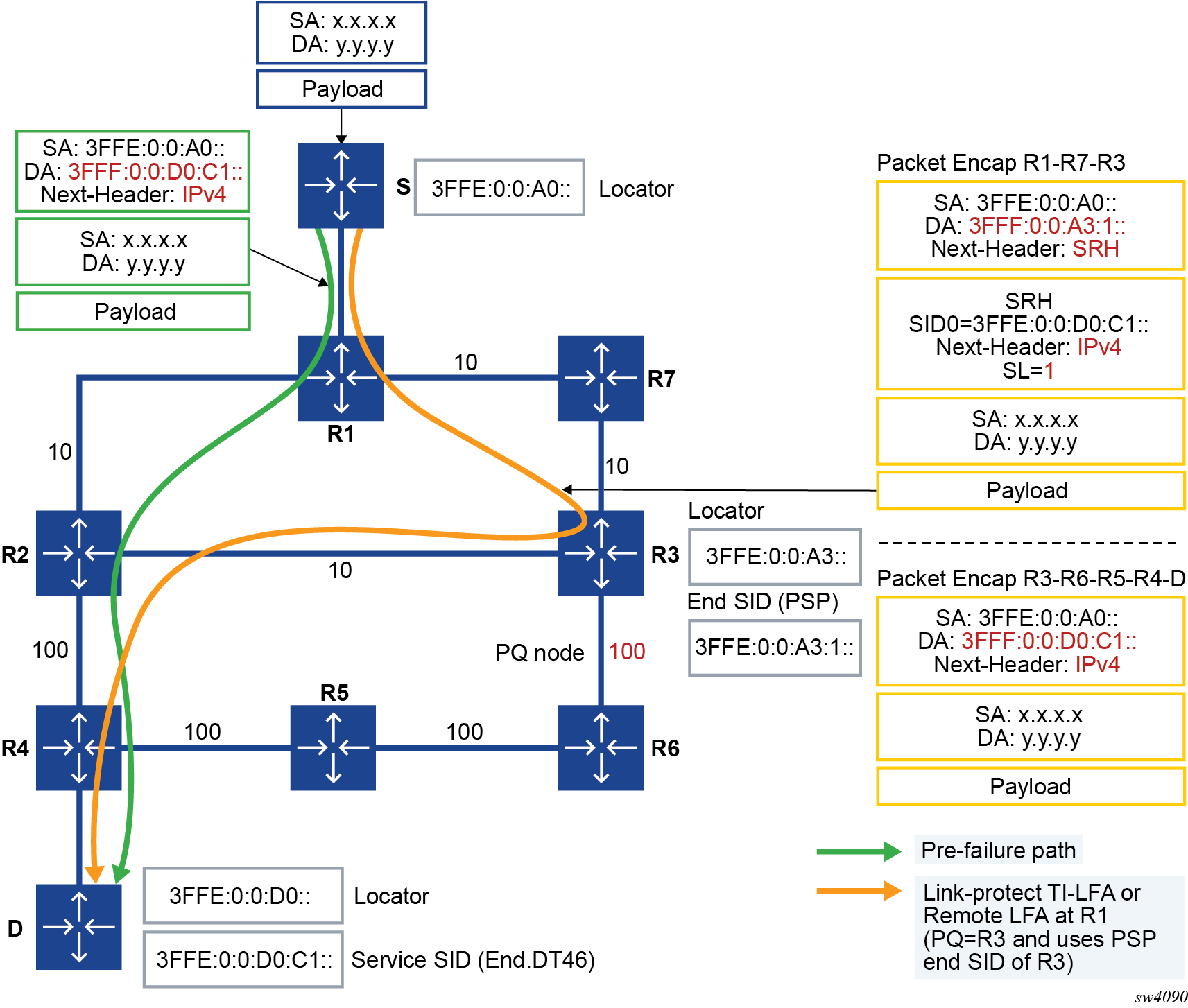
The base LFA, remote LFA, and TI-LFA features operate with SRv6 tunnels in the same way as with SR-MPLS tunnels.
To enable LFA on an IS-IS instance, use the loopfree-alternate admin-state enable command. For details, see Configuring LFA.
Remote LFA (RLFA) and TI-LFA are, configured with remote-lfa and ti-lfa options under network-instance default protocols isis loopfree-alternate context. For details, see Configuring Remote LFA and Configuring TI-LFA.
The TI-LFA algorithm prefers a micro-segment locator over a regular locator when both are present. As such, a micro-segment path may protect a regular SRv6 path.
Route table, FIB table, and tunnel table support
The following tables and information are needed to process a SRv6 packet at service origination, service termination, and transit router roles.
Route table and FIB
SRv6 locator and SID resolution is performed in the RTM and forwarding of all SRv6 packets is performed in the FIB.
The TTM is used to save details of the SRv6 tunnel but is not used directly to forward user or CPM originated packets.
The RTM and FIB are programmed with the routes of the local and remote locators, the local End.X SIDs, and the local End SIDs.
When a policy is applied to export SRv6 routes from the route table to another IS-IS instance, only the IP Reachability TLV and the locator TLV, along with the End SID sub-TLVs, are advertised by the receiving IS-IS instance. Local End, End.X, and LAN End.X routes are not exported nor advertised as separate routes.
-
remote locator (route owner = SRv6 IS-IS)
All routers in the SRv6 domain populate a resolved remote locator prefix received in the SRv6 Locator TLV in the route table and the FIB.
A SRv6 packet is always forwarded out in the datapath using the FIB.
For algorithm 0, the same prefix is advertised with the IP reach prefix TLV and the SRv6 Locator TLV. A single route entry is programmed in the route table and the FIB.
The prefix of an IGP flexible algorithm locator TLV is never advertised with an IP reach prefix TLV. Therefore, the route of the locator TLV is programmed in the route table and the FIB.
-
remote locator with up to 64 ECMP next hops
IS-IS models a remote locator prefix with two or more ECMP next hops as an IGP route with tunneled next hops using a protected NHLFE with hardware PG-ID per tunneled next hop.
This implementation provides uniform failover in ECMP. IS-IS allocates a hardware PG-ID to each next hop it establishes an adjacency with. That PG-ID is then used when programming SRv6 routes of a remote locator and of a local adjacency that resolve to this next hop.
The route table manager programs the route into the FIB. IS-IS creates an SRv6 tunnel for the locator prefix. The tunnel is added to the tunnel table. The IS-IS route entries in the route table and the FIB point to the tunnel ID of this tunnel in the tunnel table.
Weighted ECMP, when enabled on the interfaces of this IS-IS instance, is supported when forwarding packets over the locator next hops.
-
remote locator with primary or backup next hops
To provide uniform failover, IS-IS models a remote locator prefix with a primary next hop or a primary and LFA backup next-hop pair as an IGP route with a tunneled next hop using a protected NHLFE with a hardware PG-ID.
The route table manager programs the route into the FIB. IS-IS creates a SRv6 tunnel for the locator prefix. The tunnel is added to the tunnel table. The IS-IS route entries in the route table and the FIB point to the tunnel ID of this tunnel in tunnel table.
-
-
local locator (route owner = SRv6)
All routers in the SRv6 domain populate a route entry in the route table and the FIB to terminate packets destined for the local locator. This is modeled like any other local route but with the SRv6-specific route owner.
-
local adjacency SID (route owner = IS-IS)
All routers in the SRv6 domain populate a route entry in the route table and FIB for each local End.X and LAN End.X adjacency SID with primary and backup next hops.
The route table and FIB entries are modeled like a remote locator prefix with primary and backup next hops.
-
local End SID (route owner = SRv6)
All routers in the SRv6 domain populate a route entry in the route table and the FIB to terminate packets destined for each local End SID. This is modeled like any other local route, but with the SRv6-specific route owner.
With micro-segment SRv6, entries pertaining to local services populate the RTM and FIB. In the FIB, those entries are aggregated. At most, 15 entries are needed to cover the whole service addressing space offered by micro-segment SRv6. The route owner is SRv6.
Tunnel Table Manager (TTM)
The tunnel table is not used directly in the SRv6 locator resolution, in SID resolution, or in packet forwarding. All resolution is performed in the RTM and forwarding is performed in the FIB.
Each resolved remote locator or local adjacency creates an entry in TTM (ROUTE_OWNER_SRV6_ISIS). The entries for remote locators and local adjacencies in the RTM and FIB point to the tunnel ID of this tunnel. The TTM entry is not used directly for forwarding SRv6 packets. However, the route resolution behavior for SRv6 services can be modified to preferentially resolve in TTMv6.
Users of route table SRv6 routes
The SRv6 locator and adjacency routes in the route table can be used to forward the following user and CPM originated packets:
-
user packets
-
ICMPv6 echo request and echo reply packets as described in the SR Linux OAM and Diagnostics Guide
-
UDP traceroute packets as described in the SR Linux OAM and Diagnostics Guide
Forwarding and terminating of any other CPM originated packets are not supported. Specifically, received management protocol and control plane protocol packets that are encapsulated in SRv6 are dropped.
If you configure the address of a BGP neighbor, an LDP peer, or an RSVP-TE LSP destination to match a locator prefix or a SID, packets are forwarded over the SRv6 tunnel but are dropped at the destination router.
Datapath support
This section describes packet processing in the datapath on ingress PE, egress PE, and transit P router roles.
SR Linux supports both regular SRv6 and micro-segment SRv6. Both modes can operate concurrently on the same platform, but it requires that the SIDs of each type come from different SID blocks.
Service origination and termination roles
The SRv6 processing is performed inline in the IP datapath when forwarding service packets over a shortest path SRv6 tunnel at service origination or when terminating an SRv6 packet with the service SID in the DA field of the outer IPv6 header.
At the ingress PE
The following occurs at the ingress PE:
-
Packet forwarded to a shortest path SRv6 tunnel
The datapath pushes the SRv6 encapsulation header on the received Layer 2 or Layer 3 service packet.
- The Outer DA field is set to service SID (End.DT4, End.DT6, End.DT46, or End.DX2 SID).
- The Outer next-header field is set to IPv4, IPv6, or Ethernet.
-
The hop-limit field in the outer IPv6 header of the SRv6 tunnel is set to 255 for all transit IPv4, IPv6, and Ethernet packets encapsulated into SRv6. The hop-limit for OAM packets originated by the CPM on the router is set according to the specific OAM probe.
The service ingress datapath forwards the packet to one of the SRv6 tunnel candidate egress network IP interfaces based on a hash of the inner packet headers. See Using flow label in load-balancing of IPv6 and SRv6 encapsulated packets for more information about the spraying of service packets over SRv6 tunnel candidate next hops.
At the egress PE
The procedure in this step is common to the transit router role and the service termination router role.
On the ingress IP network interface, the SRv6 feature concurrently performs two IPv6 address lookups on a received IPv6 packet:- A first (longest prefix match) lookup checks if the address in the outer header DA field matches either an SRv6 local locator subnet, a local service SID, a local End function or a local End.X function. This first lookup is for the current SID.
- A second lookup is performed on the next SID in the SRH (when the IPv6 packet has an SRH). The SRv6 feature reads next SID using the index value after decrementing the Segments-Left field.
The subsequent processing depends on the outcome of the first lookup:
-
If the match is on a local service SID:
-
If the payload type is IPv4, IPv6, or Ethernet, the packet is forwarded to the service function processing; see step 2 for more details.
The payload type refers to the value of the last next-header field in the processing chain of the packet. This could be the next-header field of the outer IPv6 packet, if there is no SRH. This could also be the next-header field of an expired SRH (Segments-Left = 0) for which the last SID matches the service SID.
Note: SR Linux advertises Maximum Segments Left (MSL)MSDvalue in the IS-ISMaximum Segments Left MSD Type sub-TLV. If the payload type indicates any other protocol, including ICMPv6 (ICMP ping packet) and UDP (potential traceroute message when hop-limit field has a value of 1), the packet is redirected to the CPM for more processing as described in the SR Linux OAM and Diagnostics Guide. Other protocol packets are dropped.
The CPM generates a specific ICMPv6 message to the address in the SA field of the processed or dropped packet depending on the protocol type and the result of the match of the address in the DA field of the packet. These ICMPv6 reply messages are summarized in ICMPv6 reply messages to extracted SRv6 packets.
-
-
If the match is on a local locator only:
-
If the payload type is IPv4, IPv6, or Ethernet, the packet is forwarded to the SRv6 FPE for potential service function processing; see step 2 for more details.
-
If the payload type indicates any other protocol, including ICMPv6 (ICMP ping packet) and UDP (potential traceroute message when hop-limit field has a value of 1), the packet is redirected to the CPM for more processing. Protocol matching ICMPv6 ping and UDP traceroute have their packets processed as described in the SR Linux OAM and Diagnostics Guide. Other protocol packets are dropped.
The CPM generates a specific ICMPv6 message to the address in the SA field of the processed or dropped packet depending on the protocol type and the result of the match of the address in the DA field of the packet. These ICMPv6 reply messages are summarized in ICMPv6 reply messages to extracted SRv6 packets.
-
-
If the match is on a specific local End function and the next SID lookup is not a local locator, the packet is processed as per the transit router role for these functions as detailed in Transit router role with or without segment termination .
-
If the match is on a specific local End function and the next SID resulted in a match on a local locator, the packet is processed as described in step 1.b with the next-header field used in the processing is that of the SRH.
-
If the match is on a specific local End.X function, regardless of the next SID match outcome the packet is processed in accordance with the transit router role for these functions; see Transit router role with or without segment termination for more information.
-
If the match is on a regular IPv6 route or there is no match, the packet is forwarded or dropped. For forwarded packets, the destination address could match the locator prefix or a regular IPv6 prefix of a remote node.
-
The procedure in this step is specific to the service termination router role.
-
When the first lookup match is on a local service SID (service SID encoded in outer DA field), service packet processing is performed inline in the network interface ingress datapath.
-
The datapath performs the detailed processing of the specific SID function as per RFC 8986. It then removes the SRv6 encapsulation headers, including SRH if any.
-
It decrements and propagates into the IPv4 TTL field or IPv6 hop-limit field of the forwarded inner packet, the minimum of the incoming outer header hop-limit and inner header hop-limit (or TTL) values.
-
It performs a lookup of the service SID and forwards the packet to the service context for further processing.
-
-
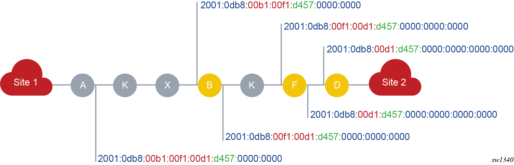
Transit router role in micro-segment SRv6
- The DA field of the IPv6 header contains a single SID (shortest path case).
- Multiple SIDs are used in the DA field and eventually in the SRH (LFA repair tunnel or SRv6 policy).
The DA field of the IPv6 header contains a single SID is of the form
2001:db8:00d1:d547::
- <
2001:0db8> is the SID block - <
00d1> is the identifier associated with a specific node - <
d547> is an identifier for a specific local service assigned by the node
2001:0db8><00d1> acts both as a locator
for the specific node and as a uN function. A packet with this address in the DA field
of the IPv6 header is routed toward the specific node with each node along the path
matching on 2001:0db8:00d1::/48 and forwarding to the predetermined
next hop.Multiple SIDs in the DA field and eventually in the SRH illustrate the following micro-segment SRv6 behavior.
- The micro-segment ID block is
2001:0db8::/32. - The node identifiers (uN) are
0x00b1for node B,0x00f1for node F, and0x00d1for node D. - Node D has advertised
2001:0db8:00d1:d457::for the specific service.
- It constructs the following container:
2001:0db8:00b1:00f1:00d1:d457:: - It places this container in the DA field of the IPv6 header.
- It forwards the packet to the next-hop determined by an LPM on that address.
Transit routers in micro-segment SRv6 illustrates the preceding example.
2001:0db8:00b1::/48 (as it has that entry in its FIB)
and performs the operation associated with that micro-segment ID:- It removes the 16-bit from the address.
- It shifts the right part toward the MSB.
- It adds a 16-bit block of zeros, the so called End of Container (EoC), as the LSB.
Node F does the same (based on matching on its own identifier).
Node D does the same but processes the packet in the service corresponding to the identifier.
It can be that the path is longer than the number of micro-SIDs that can be compressed in 128 bits. In that case, an SRH is used to convey the rest of the path. Each container in the SRH must be of the same form (a block part followed by a sequence of micro-SIDs). At some node along the path, because of the shift operations, the container in the IPv6 DA expires. At that node, micro-segment SRv6 implements a regular SRv6 END function (or END.X function if the match is on a uA).
For example, if node B receives a packet with 2001:0db8:00b1:: in the DA
field, it detects that its own identifier is followed by an EoC. Node B copies the next
segment or container from the SRH in the DA field.
Transit router role with or without segment termination
The following steps summarize the packet processing for the transit router role. For more information about the specific processing of the SID function see RFC 8986.
The procedure in this step is common to the transit router role and the service termination router role.
On the ingress IP network interface, the SRv6 feature concurrently performs two IPv6 address lookups on a received IPv6 packet:- A first (longest prefix match) lookup checks if the address in the outer header DA field matches either an SRv6 local locator subnet, a local service SID, a local End function, or a local End.X function. This first lookup is for the current SID.
- A second lookup is performed on the next SID in the SRH (when the IPv6
packet has an SRH). The SRv6 feature reads next SID using the index value
after decrementing the
Segments-Leftfield.Note: SR Linux advertises Maximum Segments Left (MSL)MSDvalue in the IS-ISMaximum Segments Left MSD Type sub-TLV.
The subsequent processing depends on the outcome of the first lookup:
-
If the match is on a local service SID:
-
If the payload type is IPv4, IPv6, or Ethernet, the packet is forwarded to the service function processing; see step 2 in section At the egress PE for more details.
The payload type refers to the value of the last next-header field in the processing chain of the packet. This could be the next-header field of the outer IPv6 packet, if there is no SRH. This could also be the next-header field of an expired SRH (
Segments-Left= 0) for which the last SID matches the service SID. If the payload type indicates any other protocol, including ICMPv6 (ICMP ping packet) and UDP (potential traceroute message when hop-limit field has a value of 1), the packet is redirected to the CPM for more processing. Protocol matching ICMPv6 ping and UDP traceroute have their packets processed as described in the SR Linux OAM and Diagnostics Guide. Other protocol packets are dropped.
The CPM generates a specific ICMPv6 message to the address in the SA field of the processed or dropped packet depending on the protocol type and the result of the match of the address in the DA field of the packet. These ICMPv6 reply messages are summarized in the table that follows.Table 14. ICMPv6 reply messages to extracted SRv6 packets Protocol Destination IP address match result ICMPv6 reply(Type/code) ICMP echo request/reply
(See SR Linux OAM and Diagnostics Guide for ICMPv6 Ping support in SRv6)
locator prefix [function | any arg] echo reply/ping successful UDP / TCP
(See SR Linux OAM and Diagnostics Guide for UDP Traceroute support in SRv6)
locator prefix [ function | any arg ] dest unreachable, port unreachable Any other protocol locator prefix [ function | any arg ] ICMP Parameter Problem/SR Upper-layer Header Error All protocols including above locator prefix | unsupported function dest unreachable, communication prohibited
-
-
If the match is on a local locator only:
-
If the payload type is IPv4, IPv6, or Ethernet, the packet is forwarded to the SRv6 FPE for potential service function processing; see step 2 in section At the egress PE for more information.
-
If the payload type indicates any other protocol, including ICMPv6 (ICMP ping packet) and UDP (potential traceroute message when hop-limit field has a value of 1), the packet is redirected to the CPM for more processing. Protocol matching ICMPv6 ping and UDP traceroute have their packets processed as described in the SR Linux OAM and Diagnostics Guide. Other protocol packets are dropped.
The CPM generates a specific ICMPv6 message to the address in the SA field of the processed or dropped packet depending on the protocol type and the result of the match of the address in the DA field of the packet. These ICMPv6 reply messages are summarized in ICMPv6 reply messages to extracted SRv6 packets.
-
-
If the match is on a specific local End function and the next SID lookup is not a local locator, the packet is processed as per the transit router role for these functions as detailed in step 2 that follows.
-
If the match is on a specific local End function and the next SID resulted in a match on a local locator, the packet is processed as described in the preceding step 1.b with the next-header field used in the processing is that of the SRH.
-
If the match is on a specific local End.X function, regardless of the next SID match outcome, the packet is processed in accordance with the transit router role for these functions; see step 2 that follows.
-
If the match is on a regular IPv6 route or there is no match, the packet is forwarded or dropped. For forwarded packets, the destination address could match the locator prefix or a regular IPv6 prefix of a remote node.
-
The procedure in this step is specific to the transit router role.
If the match is on a local End or End.X SID, the SID termination processing is performed on the packet.
-
If the End or End.X SID is the last SID in the packet encapsulation, meaning there is no SRH or there are only expired SRHs (
Segments-Left= 0), the packet is sent to the CPM for further processing.Note: The CPM processes ICMPv6 ping packets and UDP traceroute packets but drops any other protocol type. See the SR Linux OAM and Diagnostics Guide for more information about the processing of ICPMv6 echo request and reply packets and UDP traceroute packets. -
If the next-header in the IPv6 header is an SRH, the
Segments-Leftfield is zero, and the next-header in the SRH is another SRH, the current SRH is removed and the remaining steps are applied on the next SRH. -
If the
Segments-Leftfield is 1 and the SRH mode of the terminated SID is PSP, the SRH is removed. Otherwise, theSegments-Leftfield is decremented and used to read and copy the next SID into the DA field of the outer IPv6 header. -
Decrement the incoming outer IPv6 header hop-limit and write it into the outer IPv6 header hop-limit field of the outgoing packet.
-
If the first SID lookup of the current SID in the FIB matched an End function, use the outcome of the second SID lookup of the next SID to forward the packet to the next hop of the next SID (in the DA field of the outer IPv6 header).
-
If the first SID lookup of the current SID in the FIB matched an End.X function, override the outcome of the second SID lookup of the next SID with the set of next hops of the adjacency and forward the packet.
-
If both the current and the next SIDs match a local End or End.X SID, the packet is forwarded as indicated in Forwarding behavior for back-to-back local SIDs.
Table 15. Forwarding behavior for back-to-back local SIDs Current SID match Next SID match Forwarding action End End - Process Current SID. Terminate Current SID.
- Copy Next SID as IPv6.DA and perform FIB lookup.
- Process Next SID. Terminate Next SID.
- If Next SID is the last SID, process the inner payload Header.
- If the inner payload header is IPv4 or IPv6, perform a FIB lookup to determine the forwarding decision.
- If the inner payload header is TCP/UDP/ICMPv6, extract the packet to CPM.
End End.X - Process Current SID. Terminate Current SID.
- Copy Next SID as IPv6.DA and perform FIB lookup.
- Process Next SID. Terminate Next SID.
- If Next SID is the last SID, process the inner payload Header. Otherwise, forward the packet to the L3 adjacency based on Next SID.
- If the inner payload header is IPv4 or IPv6, perform a FIB lookup to determine the forwarding decision.
- If the inner payload header is TCP/UDP/ICMPv6, extract the packet to CPM.
End.X End - Process Current SID. Terminate Current SID.
- Copy Next SID as IPv6.DA and forward the packet to the L3 adjacency based on the current SID.
- The peer node would send this packet back.
- Process Next SID (this has become the Current SID).
- If Next SID is the last SID, process the inner payload Header.
- If the inner payload header is IPv4 or IPv6, perform a FIB lookup to determine the forwarding decision.
- If the inner payload header is TCP/UDP/ICMPv6, extract the packet to CPM.
End.X End.X - Process Current SID. Terminate Current SID.
- Copy Next SID as IPv6.DA and forward the packet to the L3 adjacency based on the current SID.
- The peer node would send this packet back.
- Process Next SID (this has become the Current SID).
- If Next SID is the last SID, process the inner payload Header. Otherwise, forward the packet to the L3 adjacency based on Next SID.
- If the inner payload header is IPv4 or IPv6, perform a FIB lookup to determine the forwarding decision.
- If the inner payload header is TCP/UDP/ICMPv6, extract the packet to CPM.
-
Using flow label in load-balancing of IPv6 and SRv6 encapsulated packets
When traffic is switched via SRv6 shortest path tunnel, flows are distributed across SRv6
tunnels and LAG links of the associated default network instance in an
ECMP manner. The default hash calculation on the ingress non-default network instance is
based on the existing hash procedures of an IPv4, IPv6, or an Ethernet packet. For IPv6
service packets, an option is provided to include the packet’s Flow Label field, when
not zero, and to hash on the triplet {SA, DA, Flow Label}. The system
load-balancing hash-options
ipv6-flow-label
command
is used to enable this behavior on an access or network interface.
The ingress non-default network instance copies the output of the hash on the inner packet headers into the flow label field of the outer IPv6 header that it pushes on the SRv6 encapsulated packet. This is regardless of whether the flow label is used or not in the computation of the hash on the service packet.
On a transit router, the hashing of SRv6 encapsulated packets can also use the Flow Label field in the outer IPv6 header to provide more entropy to the load-balancing process of SRv6 packets. The system load-balancing hash-options ipv6-flow-label command can be configured on a network facing subinterface to hash on the triplet {SA, DA, Flow Label}. By default, a transit router only hashes on the tuple {SA, DA} in the header of a received IPv6 packet with a non-zero flow label field, including when the packet is SRv6.
Interaction with other datapath features
The following describes the interaction of the SRv6 feature with other datapath features:
-
When SRv6 is enabled on default network instance, datapath enables forwarding and receiving SRv6 encapsulated packets on all network facing sub interfaces. The datapath, however, drops an SRv6 encapsulated packet if received from or needs forwarding to a(non default network instance). A service packet received on either a compatible network instance such as
defaultnetwork instance or aip-vrfnetwork instance an be encapsulated into an SRv6 packet and forwarded via default network-instance. -
The SRv6 feature performs concurrently a couple of IPv6 address lookups on a packet received with an SRH on a default sub interface. The first lookup is for the current SID in the DA field in the header of the received SRv6 packet and the second is for the next SID in the SRH.
SRv6 tunnel metric and MTU settings
IGP sets the metric of the SRv6 remote locator prefix route and tunnel or that of a local adjacency SID route to the metric of the computed path of the corresponding route.
The metric of a local End SID route is set to 0, similar to any local route.
The metric of a BGP IPv4/IPv6 or VPN-IPv4/VPN-IPv6 route resolved to a SRv6 tunnel inherits the value of the locator prefix route metric.
You must configure the network interfaces at the ingress PE and at transit P routers with an MTU value that accounts for the fixed IPv6 header (40 bytes) and the additional LFA SRHs (24 bytes each).
In addition, there are network deployments where it is not possible to modify the network interface MTU or to set all network interfaces to the same value. In that case, you must configure the outgoing network interface to reflect this worst case MTU in the network, accounting fixed and variable LFA overhead. The following is the CLI to use for this purpose.
BGP service control plane extensions
The BGP service control plane required extensions are specified in RFC 9252, BGP Overlay Services Based on Segment Routing over IPv6 (SRv6). BGP requires some changes in the IPv6, VPN-IPv4, VPN-IPv6, and EVPN family routes so that the egress PE can signal the following End programming behaviors to the ingress PE:
-
Layer 2 SRv6 service SIDs
- End.DX2
- Layer 2 decapsulation and cross-connect to an Epipe egress SAP, signaled by AD per-EVI routes
-
Layer 3 SRv6 service SIDs
- End.DT4
- a IP-VRF (or
defaultnetwork instance) route-table lookup, signaled by VPN-IPv4 or EVPN in Interface-less (EVPN-IFL) IPv4 prefix routes (also by IPv4) - End.DT6
- a IP-VRF (or GRT) route-table IPv6 lookup, signaled by VPN-IPv6 or EVPN-IFL IPv6 prefix routes (also by IPv6)
- End.DT46
- a IP-VRF route-table lookup for IPv4 or IPv6 prefixes, signaled by VPN-IPv4 or VPN-IPv6 or EVPN-IFL IPv4 or IPv6 prefix routes
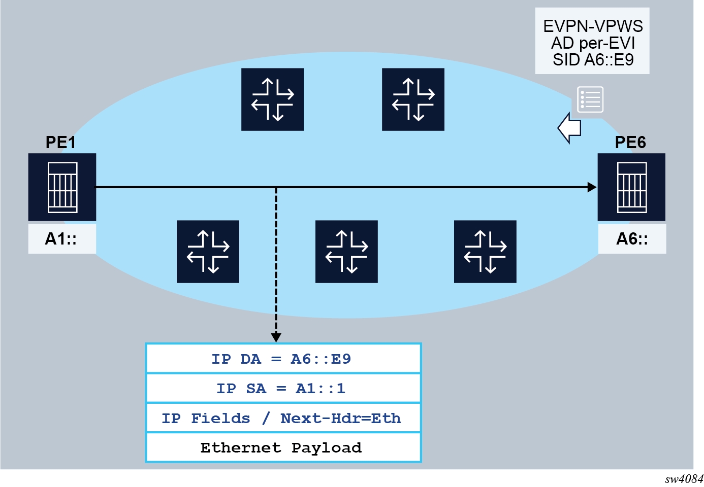
The ingress and egress PEs behave as follows:
-
The egress PE (PE6) advertises an A-D per EVI route with the SRv6 Service SID that identifies the End.DX2 behavior. The service SID includes the configured locator in the Epipe (A6::), as well as the allocated function (E9), which identifies the Epipe at the egress PE.
-
The ingress PE (PE1) imports the A-D per EVI route and creates an EVPN destination in the corresponding Epipe to A6::E9.
-
When PE1 receives frames at the non-default network.instance, it encapsulates the frames into an SRv6 packet using the configured IP SA. The IP DA is the EVPN destination SID.
-
Shortest path forwarding is considered in the example shown in End.DX2 behavior for EVPN-VPWS, and therefore the EVPN destination SID is encoded in the IP DA. If TI-LFA is required, PE1 modifies the encapsulation to include an SRH and additional SIDs.
-
When the SRv6 packet arrives at PE6, the SID encoded in the IP DA identifies the packet for termination on PE6 and the Epipe for decapsulation and forwarding.
Similar procedures are followed for the other required services.
The following table lists the functions that micro-segment SRv6 implements to support the requirements.
| SID function endpoint behavior | Codepoint | SID type: End.SID | SID type: End.X SID | SID type: LAN End.X SID | Advertising protocol | Supported |
|---|---|---|---|---|---|---|
| uDT6 | 62 | Yes | No | No | BGP or static | Yes1 |
| uDT4 | 63 | Yes | No | No | BGP or static | Yes1 |
| uDT46 | 64 | Yes | No | No | BGP or static | Yes1 |
| uDX2 | 65 | Yes | No | No | BGP or static | Yes1 |
BGP extensions
The following BGP extensions are supported, as defined in RFC 9252:
-
The following SRv6 Service TLVs:
-
SRv6 Service TLV encoded in the BGP Prefix-SID attribute
-
SRv6 SID Information Sub-TLV (SRv6 Service Sub-TLV type 1) encoded in the SRv6 Service TLV
-
SRv6 SID Structure Sub-Sub-TLV (SRv6 Service Data Sub-Sub-TLV type 1)
-
-
Transposition of 16 or 20 bits of the FUNCTION to the Label field of the NLRI
- Arg.FE2 arguments used for split-horizon filtering in EVPN multihoming, advertised in the EVPN AD per-ES routes with 16 bits of the argument transposed to the label field of the ESI Label extended community.
The BGP extensions are applied to the following routes by setting the behavior field in the SRv6 Services TLV, as defined in RFC 8986:
-
VPN-IPv4
-
VPN-IPv6
-
IPv4
-
IPv6
-
EVPN AD per-EVI
-
EVPN AD per-ES
Advertising SRv6 service TLVs
The EVPN, VPN-IPv4, VPN-IPv6, IPv4, and IPv6 routes for the SRv6-enabled services are advertised along with the SRv6 Service TLV. The TLV format is described in RFC 9252 and shown in the following figure.
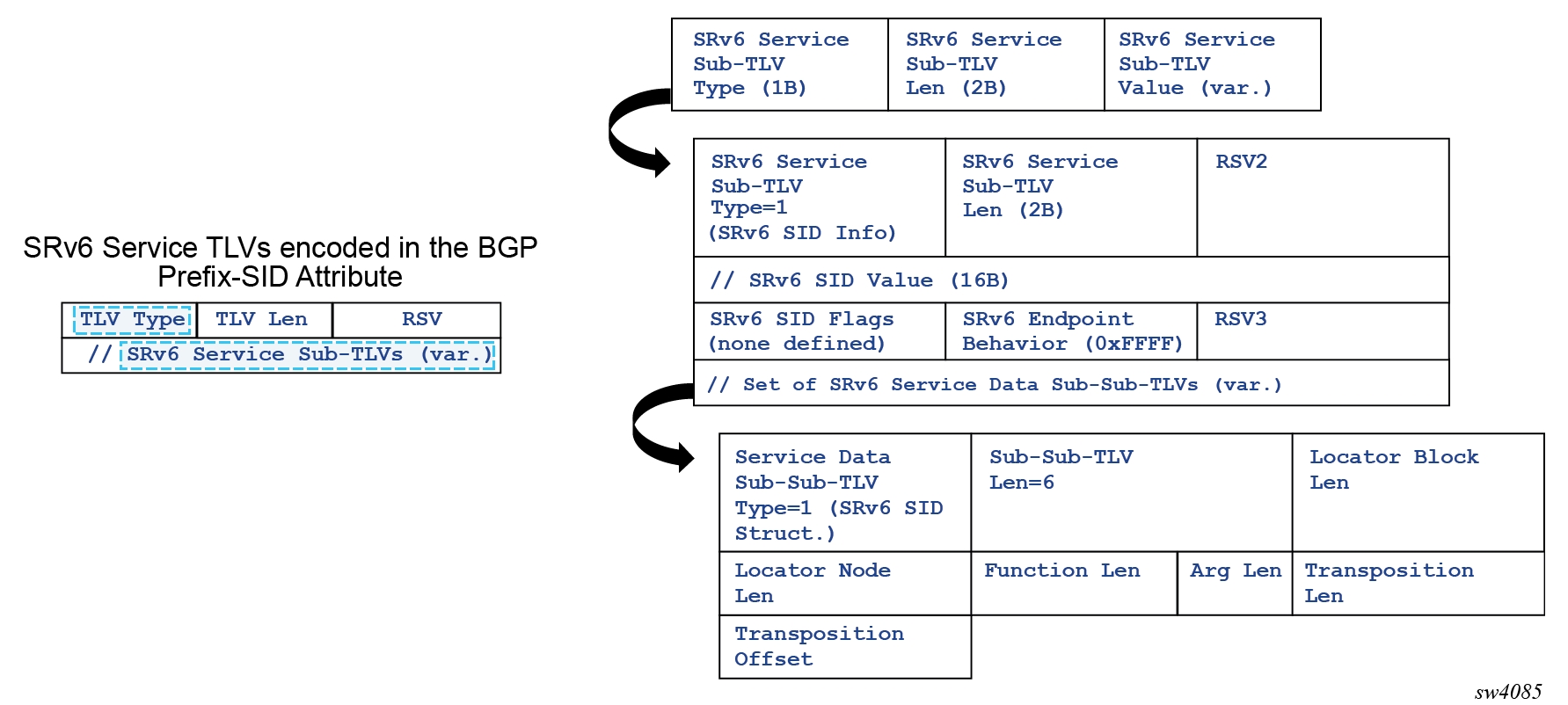
The SRv6 Service TLV encoded in the BGP Prefix-SID attribute can have two different types:
-
Type 5 is used for Layer 3 service SIDs or the SIDs signaled for IP-VRF services with VPN-IP or EVPN-IFL routes. Layer 3 service SIDs are also supported for the base router along with IPv4 or IPv6 routes.
-
Type 6 is used for Layer 2 service SIDs or the SIDs signaled for VPWS (or MAC-VRF) services. Type 6 is supported along with AD per-EVI and per-ES routes for Epipes.Note: MAC-VRF is not supported in SR Linux.
The SRv6 Service TLV may contain an unordered list of sub-TLVs, but currently the SRv6 Service TLV is advertised with only one sub-TLV: the SRv6 SID Info sub-TLV (type 1). This sub-TLV encodes the following information:
-
For the SID value, the entire 128-bit SID is allocated to the service, including the locator configured for the service and the allocated FUNCTION (which can be dynamically allocated or statically configured on the service). The ARGUMENT is always 0.
-
SID flags are all zero.
- Endpoint behavior encodes the behavior as in RFC 8986, in decimal values. The
following values are relevant for SR Linux:
-
18 – End.DT6
-
19 – End.DT4
-
20 – End.DT46
-
21 – End.DX2
-
24 – End.DT2m (only for AD per-ES routes)
-
-
One SID Structure Sub-Sub-TLV (Service Data Sub-Sub-TLV type 1)
The SID Structure Sub-Sub-TLV is always included in routes with label fields and always uses the following values when advertised:
-
Locator Block Length - encodes the length of the block configured in the locator for the service, default value of 32
-
Locator Node Length - the length of the node configured in the locator for the service, default value of 16
-
Function Length - default value of 16
-
Argument Length - 0 (default) or 16 (configured)
-
Transposition Length (TL) - 20 for EVPN and VPN-IP routes with full SIDs and 16 for micro segments and 0 for IP routes in the base router
-
Transposition Offset (TO)
-
for EVPN and VPN-IP routes:
-
If the Function Length equals 20 or 16, the Transposition Offset (TO) value equals the prefix length configured in the locator
If the Function Length is greater than 20, the TO value equals:
(prefix length configured in the locator) + (FunctLength 20)
-
-
for IP routes in base router, TO value is always 0
-
-
For IP routes in the base router, the TO value is always 0.
Configuring a BGP global SRv6 source address
To encapsulate SRv6 within a BGP IPv6 unicast session, you must first configure the address families and establish the BGP IPv6 unicast session, and then use the network-instance.protocols.bgp.srv6.source-address command to specify the SRv6 source address for encapsulation.
In the following configuration example, the BGP instance includes an SRv6 block that sets the source address 2001:db8:100::1. The router (10.0.0.1) uses the IPv6 address 2001:db8:100::1 as the source address for all BGP IPv6-unicast sessions, enabling the BGP session to be carried over the SRv6 infrastructure.
--{ + candidate shared default }--[  ]--
# info with-context network-instance default protocols bgp
   network-instance default {
        protocols {
            bgp {
                admin-state enable
                autonomous-system 65001
                router-id 10.0.0.1
                afi-safi ipv6-unicast {
                    admin-state enable
                }
                srv6 {
                    source-address 2001:db8:100::1
                }
            }
        }
    }
Enabling SRv6 TLVs for IPv4‑unicast BGP routes
You can enable SRv6 TLVs for IPv4‑unicast BGP routes by using the command network-instance protocols bgp afi-safi ipv4-unicast ipv4-unicast srv6 add-srv6-tlvs.
--{ + running }--[  ]--
# info with-context network-instance default protocols bgp afi-safi ipv4-unicast ipv4-unicast srv6
    network-instance default {
        protocols {
            bgp {
                afi-safi ipv4-unicast {
                    ipv4-unicast {
                        srv6 {
                            add-srv6-tlvs {
                                locator-name srl_loc1
                            }
                        }
                    }
                }
            }
        }
    }
Enabling SRv6 TLVs for IPv6‑unicast BGP routes
You can enable SRv6 TLVs for IPv6‑unicast BGP routes by using the command network-instance protocols bgp afi-safi ipv6-unicast ipv6-unicast srv6 add-srv6-tlvs.
--{ + running }--[  ]--
# info with-context network-instance default protocols bgp afi-safi ipv6-unicast ipv6-unicast srv6
    network-instance default {
        protocols {
            bgp {
                afi-safi ipv6-unicast {
                    ipv6-unicast {
                        srv6 {
                            add-srv6-tlvs {
                                locator-name srl_loc1
                            }
                        }
                    }
                }
            }
        }
    }
Processing SRv6 TLVs for IPv4‑unicast BGP routes
To process received SRv6 TLVs for IPv4-unicast BGP routes, set the parameter
process-received-srv6-tlvs within the command
network-instance protocols bgp afi-safi ipv4-unicast ipv4-unicast srv6
context to true.
--{ +* candidate shared default }--[  ]--
# info with-context network-instance default protocols bgp afi-safi ipv4-unicast ipv4-unicast srv6
    network-instance default {
        protocols {
            bgp {
                afi-safi ipv4-unicast {
                    ipv4-unicast {
                        srv6 {
                            process-received-srv6-tlvs true
                            add-srv6-tlvs {
                                locator-name srl_loc1
                            }
                        }
                    }
                }
            }
        }
    }
Processing SRv6 TLVs for IPv6‑unicast BGP routes
To process received SRv6 TLVs for IPv6-unicast BGP routes, set the parameter
process-received-srv6-tlvs within the command
network-instance protocols bgp afi-safi ipv6-unicast ipv6-unicast srv6
context to true.
--{ + running }--[  ]--
# info with-context network-instance default protocols bgp afi-safi ipv6-unicast ipv6-unicast srv6
    network-instance default {
        protocols {
            bgp {
                afi-safi ipv6-unicast {
                    ipv6-unicast {
                        srv6 {
                            process-received-srv6-tlvs true
                            add-srv6-tlvs {
                                locator-name srl_loc1
                            }
                        }
                    }
                }
            }
        }
    }
Transposition procedures when advertising service routes
The purpose of the SID Structure Sub-Sub-TLV is twofold:
-
Advertise the structure of the SRv6 SID used in the service, including the length of the Locator block, node, function and argument.
-
Support transposition procedures for efficient service route packing. The FUNCTION is transposed into the label field in the route’s NLRI. Because the rest of the SID is common for routes of the same type in the service, this transposition operation supports efficient packing of routes into the same BGP update.
The following figure shows how the FUNCTION part of the SID is transposed. This example illustrates how transposition works for EVPN-VPWS, and it would be similar for VPN-IP routes.
In the preceding figure, PE6 is configured with an Epipe that uses a configured locator with LB length = 40 bits and LN length = 24 bits. The Function length is set at 24, and 20 bits are always transposed into the NLRI (non-configurable). In the preceding figure, the following rules apply:
-
On reception, the router can build any SID out of the received route, irrespective of transposition, as long as the lengths are correctly encoded.
-
On transmission, the system performs a transposition for VPN-IP and EVPN service routes as follows:
-
The following rules apply for Function Length:
-
If Function Length is greater than 20 in the Locator configuration, the function bits are put at the right-most bits of the L bits. For example, if LB LEN is 40 bits and the LN Len is 24 bits:
-
If Function Length = 20, the entire function is transposed into the label field, and the following is signaled in the route:
Length [LBL, LNL, FL, AL] : [40, 24, 20, 0]
TL:20, TO:64
-
Supported service routes for SRv6
The supported service routes for SRv6 are:
-
IPVRF services, configured for SRv6:
-
VRF -IPv4 routes
-
VRF -IPv6 routes
-
-
Base router
-
IPv6 routes, if configured for SRv6 in IPv6 family
-
IPv4 routes, if configured for SRv6 in IPv4 family
-
-
Epipe services, configured for SRv6:
-
EVPN AD per-EVI routes
-
EVPN AD per-ES routes, for VPWS that make use of Ethernet Segments
-
Removing SRv6 TLVs from IPv4‑unicast routes for a BGP peer‑group
You can configure a BGP group to remove any SRv6 TLVs from received IPv4-unicast
updates by setting the parameter strip-srv6-tlvs within the
command network-instance protocols bgp group afi-safi ipv4-unicast
ipv4-unicast srv6 context to true.
--{ + running }--[  ]--
# info with-context network-instance default protocols bgp group group_1 afi-safi ipv4-unicast ipv4-unicast srv6
    network-instance default {
        protocols {
            bgp {
                group group_1 {
                    afi-safi ipv4-unicast {
                        ipv4-unicast {
                            srv6 {
                                strip-srv6-tlvs true
                            }
                        }
                    }
                }
            }
        }
    }
Removing SRv6 TLVs from IPv6‑unicast routes for a BGP peer‑group
You can configure a BGP group to remove any SRv6 TLVs from received IPv6-unicast
updates by setting the parameter strip-srv6-tlvs within the
command network-instance protocols bgp group afi-safi ipv6-unicast
ipv6-unicast srv6 context to true.
--{ + running }--[  ]--
# info with-context network-instance default protocols bgp group group_1 afi-safi ipv6-unicast ipv6-unicast srv6
    network-instance default {
        protocols {
            bgp {
                group group_1 {
                    afi-safi ipv6-unicast {
                        ipv6-unicast {
                            srv6 {
                                strip-srv6-tlvs true
                            }
                        }
                    }
                }
            }
        }
    }
Discarding BGP learned SRv6 routes
You can discard any BGP learned routes that carry SRv6 TLVs using the command network-instance protocols bgp neighbor srv6 drop-routes-with-srv6-tlvs.
Discarding the BGP learned SRv6 routes
In the following configuration example, the router is set up to drop any BGP-learned routes that carry SRv6 TLVs for a specific neighbor (10.1.1.2) that belongs to the EBGP-UNDERLAY peer-group.
--{ + candidate shared default }--[  ]--
# info with-context network-instance default protocols bgp neighbor 10.1.1.2
    network-instance default {
        protocols {
            bgp {
                neighbor 10.1.1.2 {
                    peer-group EBGP-UNDERLAY
                    srv6 {
                        drop-routes-with-srv6-tlvs true
                    }
                }
            }
        }
    }
BGP next hop for SRv6 service routes
As specified in RFC 9252, BGP Overlay Services Based on Segment Routing over IPv6 (SRv6), the egress PE may set the next hop to any of its IPv6 addresses. When the IPv6 address value is not covered by the SRv6 locator from which the SRv6 Service SID is allocated, the ingress PE performs reachability checks for the SRv6 Service SID in addition to the BGP next-hop reachability procedures.
- On reception of a BGP SRv6 service route, both the locator and the next hop are resolved independently in the route table.
- For base instance routes (not service routes), the network-instance protocols bgp afi-safi ipv6-unicast ipv6-unicast srv6 process-received-srv6-tlvs true command triggers the independent resolution of the next hop and the locator reachability (and collates their states that drive route programming). The locator state is considered only if this command is configured.
- Whether the router performs network-instance protocols bgp group next-hop-self, there is no effect on the RIB-IN processing and reachability because the next-hop behavior is a RIB-OUT parameter.
- If a received route has a resolved next hop but unresolved locator, the show network-instance default protocols bgp route command shows "valid/best" but not "used" in the route flags.
Route policy support for matching and modifying BGP SRv6 service routes
Route-matching criteria and route-modifying actions that are specific to BGP routes carrying SRv6 TLVs can be configured for route policies.
Specifying SRv6 TLV match criteria
You can specify SRv6 TLV presence as a match criterion for BGP route using the command routing-policy policy statement match bgp srv6 tlv.
If srv6 tlv is configured as present, the policy entry matches only those BGP routes that carry the SRv6 TLVs. When configured as not present, the policy entry matches only those BGP routes that do not include the SRv6 TLVs.
In the following configuration example, the policy entry matches only those BGP routes that carry the SRv6 TLVs.
--{ +* candidate shared default }--[  ]--
# info with-context routing-policy policy policy01
    routing-policy {
        policy policy01 {
            statement 100 {
                match {
                    bgp {
                        srv6 {
                            tlv present
                        }
                    }
                }
            }
        }
    }
Specifying SID prefix match criteria for BGP routes
You can specify SRv6 TLV presence as a match criterion for BGP route using the command routing-policy policy statement match bgp srv6 sid-prefix.
When a sid-prefix is configured, the policy entry matches only those BGP routes whose associated SID prefix equals or falls within the defined prefix range.
In the following configuration example, the policy entry matches only those BGP
routes that have an SRv6 SID (or uSID) within the
prefix 2001:db8:100::/48.
--{ +* candidate shared default }--[  ]--
# info with-context routing-policy policy policy01
    routing-policy {
        policy policy01 {
            statement 100 {
                match {
                    bgp {
                        srv6 {
                            sid-prefix 2001:db8:100::/48
                        }
                    }
                }
            }
        }
    }
Specifying SRv6 locator action in a routing policy
You can specify the SRv6 locator action to BGP routes that match a policy statement.
The following configuration identifies a BGP policy (policy01) matching routes with an SRv6 TLV and applies the SRv6 locator srl_loc1 action to guide SRv6 traffic for those routes.
--{ + running }--[  ]--
# info with-context routing-policy policy policy01
    routing-policy {
        policy policy01 {
            statement 100 {
                match {
                    bgp {
                        srv6 {
                            tlv present
                        }
                    }
                }
                action {
                    bgp {
                        srv6 {
                            locator srl_loc1
                        }
                    }
                }
            }
        }
    }
BGP Link State (BGP-LS) extensions for SRv6
For information about BGP-LS extensions for SRv6 supported in SR Linux, see the "BGP Link-State" section of the SR Linux Routing Protocols Guide.
Service extensions
The following section describes the service extensions for originating and terminating SRv6 services and applies to both regular and micro-segment SRv6, unless stated otherwise.
SRv6 IP-VRF services
SRv6 for IP-VRF allows the transport of IP-VRF-related IPv4 and IPv6 data across an SRv6-enabled network. To this end, IP-VRF-related data is sent to an ingress SRv6 router, where it is encapsulated and forwarded via an SRv6 tunnel. The SRv6 tunnel transports the encapsulated data across the SRv6-enabled network to an egress SRv6 router, where it is decapsulated and forwarded further as IP-VRF-related data. SRv6-tunneled data is encapsulated using an IPv6 header, where the destination address is a unique SRv6 segment identifier (SID), and is processed and forwarded in the IPv6 data plane.
An SRv6 SID is a preconfigured 128-bit routable IPv6 prefix address that is encoded in three parts: a locator, a function, and an argument. The locator is a summary IPv6 prefix for a set of SRv6 SIDs instantiated on an SRv6-capable router. It is used to route the data within the IPv6 transport network. Each participating SRv6-capable router needs its unique locator, based on a common block that all participating SRv6-capable routers share in the IPv6 address space. The function is an opaque identifier that indicates the local behavior at the endpoint of an SRv6 segment. The focus in this topic is on the SRv6 End.DT4 and the SRv6 End.DT6 functions for the IP-VRF, performing a prefix lookup in the IP-VRF service IPv4 route table (End.DT4) or in the IP-VRF service IPv6 route table (End.DT6). The argument is not used in SR Linux and is set to all zeros.
The local router installs its locator prefix in its IPv6 route table and forwarding information base (FIB), and advertises its locator prefix in IS-IS with the SRv6 locator sub-TLV. Each remote router populates its route table and FIB with the received locator prefixes, including the tunneled next hop to the originating router. Each remote router also populates its IP-VRF service route table with the received network prefixes, including the tunneled next hop to the IP-VRF of the originating router.
Configuring IP-VRF for SRv6
IP-VRF services support SRv6 End.DT4, End.DT6, and End.DT46 behaviors. IP-VRFs support IPv4 and IPv6 routes that are advertised in the VPN-IPv4 and VPN-IPv6 families, as well as EVPN IP prefix routes in Interface-less mode.
In the following configuration example, an IP-VRF instance
IPVRF1 is created and the SRv6 segment-routing instance 1
is defined with locator srl_loc1. The BGP-IPVPN instance 1 is
then configured to use that SRv6 instance (default-locator srl_loc1
instance 1) with source address 2001:db8:100::1.
--{ + running }--[ ]--
# info with-context network-instance IPVRF1 protocols bgp-ipvpn bgp-instance 1 srv6
network-instance IPVRF1 {
protocols {
bgp-ipvpn {
bgp-instance 1 {
srv6 {
default-locator srl_loc1
                    instance 1
source-address 2001:db8:100::1
}
}
}
}
}
EVPN VPWS services with SRv6
Service providers prefer an optimized, standardized, and unified control plane for VPNs. EVPN-VPWS is supported in SRv6 networks that may also run other EVPN-based services, such as EVPN-based VPLS services or Layer 3 EVPN IFL (interface-less) services. From a control plane perspective, EVPN-VPWS is a simplified point-to-point version of RFC 7432, because there is no need to advertise MAC/IP advertisement routes in VPWS. EVPN-VPWS is described in RFC 8214, and the signaling aspects to support SRv6 are specified in RFC 9252.
EVPN-VPWS supports all-active multihoming (per-flow load-balancing multihoming) as well as single-active multihoming (per-service load-balancing multihoming), using the same Ethernet segments (ESs) used for EVPN-based VPLS services. EVPN-VPWS uses route type 1 and route type 4; it does not use route types 2, 3, or 5, because MAC/IP routes, inclusive multicast routes, or IP-prefix routes are not required.
EVPN-VPWS uses AD per-EVI routes, and optionally, if multihoming is used, AD per-ES and ES routes are required:
-
route type 1 - Auto-discovery per EVPN instance (AD per-EVI). This route type is used in all EVPN-VPWS scenarios, with or without multihoming. For EVPN-VPWS, the Ethernet tag field is encoded with the local attachment circuit (AC) of the advertising PE. This value is configured using the network-instance protocols bgp-evpn bgp-instance vpws-attachment-circuits local local-attachment-circuit ethernet-tag command. The route distinguisher (RD), label, and the Ethernet segment identifier (ESI) are encoded as for EVPN-based VPLS. The label field is used as service label. In case of multihoming, AD per-EVI routes containing the same ESI are used to provide aliasing and a backup path to the PEs part of the ES. The L2 MTU field is encoded with the service MTU configured in the Epipe. The flags used for EVPN-VPWS are:
-
Flag C: this flag is set if a control word is configured in the service; however, this does not apply if the transport is SRv6.
-
Flag P: this flag is set if the advertising PE is a primary PE.
-
If no multihoming is used, there is no primary PE (P = 0).
-
In all-active multihoming, all PEs in the ES are primary (P = 1).
-
In single-active multihoming, only one PE per-EVI in the ES is a primary (P = 1).
-
-
Flag B: this flag is set if the advertising PE is a backup PE.
-
Flag B is only set in case of single-active multihoming and only for one PE, even if more than two PEs are present in the same single-active ES. The backup PE is the winner of the second designated forwarder (DF) election (excluding the DF). The remaining non-DF PEs send B = 0.
-
If there is no multihoming, the ESI, flag P, and flag B are set to zero.
-
-
route type 1 - Auto-discovery per Ethernet segment (AD per-ES). This route type has the same encoding as for EVPN-based VPLS. The AD per-ES route is only used in multihoming scenarios where it is advertised from the PE for each ES. This route type carries the ESI label (used for split-horizon, but only for VPLS services and not for Epipe services) and can affect procedures such as the DF election, as well as the aliasing on remote PEs.
-
route type 4 - ES route. This route type has the same encoding as for EVPN-based VPLS. The ES route is only used in multihoming scenarios. This route type advertises a local configured ES. The exchange of this route type can discover remote PEs that are part of the same ES and the DF election algorithm among them.
Configuring EVPN VPWS services with SRv6
To configure EVPN-VPWS over SRv6, use the command network-instance protocols bgp-evpn bgp-instance vpws-attachment-circuits local local-attachment-circuit srv6.
The following example configures a EVPN VPWS service with SRv6
--{ + candidate shared default }--[  ]--
# info with-context network-instance vpws_srl
    network-instance vpws_srl {
        type vpws
        admin-state enable
        interface ethernet-1/32.1 {
            connection-point cp1
        }
        protocols {
            bgp-evpn {
                bgp-instance 1 {
                    admin-state enable
                    encapsulation-type srv6
                    evi 1
                    vpws-attachment-circuits {
                        local {
                            local-attachment-circuit ac_1 {
                                ethernet-tag 1
                                connection-point cp2
                                srv6 {
                                    default-locator srl_loc1
                                    instance 1
                                }
                            }
                        }
                        remote {
                            remote-attachment-circuit ac_1 {
                                ethernet-tag 1
                                connection-point cp2
                            }
                        }
                    }
                    srv6 {
                        source-address 2001:db8:100::1
                    }
                }
            }
        }
        connection-point cp1 {
        }
        connection-point cp2 {
        }
        segment-routing {
            srv6 {
                instance 1 {
                    locator srl_loc1 {
                        full-segment {
                            function {
                                end-dx2 {
                                    value 800
                                }
                            }
                        }
                    }
                }
            }
        }
    }
SRv6 data and control plane operation
The following figure shows the operation of the data and control planes when an IP-VPN route is resolved to an SRv6 tunnel.
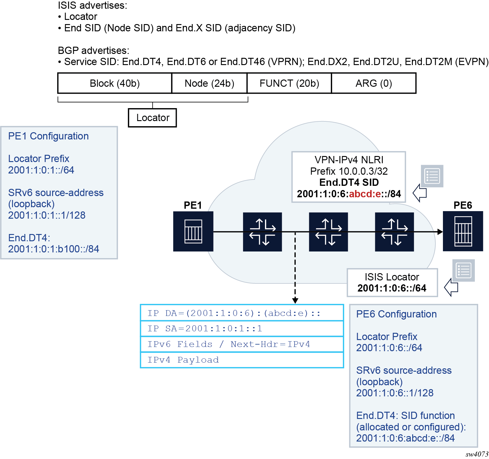
The PE6 egress router advertises the locator route that contains its locator prefix and, optionally, a local node SID (End) in IS-IS. It also advertises the SID of each adjacency (End.X) to its IS-IS neighbors.
The locator prefix provides the route to reach PE6 and is used by other routers to forward an SRv6 packet destined for any SID owned by PE6. Other routers use the End and End.X SIDs to create the repair tunnel for the Remote LFA and TI-LFA backup paths.
In BGP, PE6 advertises a VPN-IPv4 route and includes the End.DT4 service SID, which is equivalent to the SR-MPLS service label in the label per-VRF model. Unlike the SR-MPLS service label, the SRv6 End.DT4 SID contains both the function value that identifies the specific VRF-ID in PE6 and the locator prefix that provides the reachability to router PE6.
The PE1 router resolves the received VPN-IPv4 route by validating the next hop and checking the reachability of the locator prefix of PE6 in the routing table. When PE1 receives an IPv4 packet from a CE node, it pushes an outer IPv6 header that contains the End.DT4 SID in the DA field and looks up the address in the routing table. The packet is then forwarded to one of the next hops of the route of the locator prefix of PE6.