VPRN Features
This section describes the 7705 SAR service features and any special capabilities or considerations as they relate to VPRN services:
IP Interfaces
VPRN customer IP interfaces can be configured with most of the same options found on the core IP interfaces. The advanced configuration options supported are:
Unnumbered interfaces (see Unnumbered Interfaces)
DHCP options (see DHCP and DHCPv6)
Local DHCP server options (see Local DHCP and DHCPv6 Server)
IPSec tunnel interfaces (see IPSec Support)
IPCP options (see IPCP)
ICMP options (see Troubleshooting and Fault Detection Services)
VRRP options (see VRRP on VPRN Interfaces)
Configuration options found on core IP interfaces not supported on VPRN IP interfaces are:
NTP broadcast receipt
Unnumbered Interfaces
Unnumbered interfaces are supported on VPRN and IES services for IPv4. Unnumbered interfaces are point-to-point interfaces that are not explicitly configured with a dedicated IP address and subnet; instead, they borrow (or link to) an IP address from another interface on the system (the system IP address, another loopback interface, or any other numbered interface) and use it as the source IP address for packets originating from the interface.
This feature is supported via both dynamic and static ARP for unnumbered interfaces to allow interworking with unnumbered interfaces that may not support dynamic ARP.
The use of unnumbered interfaces has no effect on IPv6 routes; however, the unnumbered command must only be used in cases where IPv4 is active (IPv4 only and mixed IPv4/IPv6 environments). When using an unnumbered interface for IPv4, the loopback address used for the unnumbered interface must have an IPv4 address. The interface type for the unnumbered interface is automatically point-to-point.
DHCP and DHCPv6
DHCP is a configuration protocol used to communicate network information and configuration parameters from a DHCP server to a DHCP-aware client. DHCP is based on the BOOTP protocol, with additional configuration options and the added capability of allocating dynamic network addresses. DHCP-capable devices are also capable of handling BOOTP messages.
A DHCP client is an IP-capable device (typically a computer or base station) that uses DHCP to obtain configuration parameters such as a network address. A DHCP server is an Internet host or router that returns configuration parameters to DHCP clients. A DHCP/BOOTP Relay agent is a host or router that passes DHCP messages between clients and servers.
DHCPv6 is not based on, and does not use, the BOOTP protocol.
The 7705 SAR can act as a DHCP client, a DHCP or DHCPv6 Relay agent, or a local DHCP or DHCPv6 server.
Home computers in a residential high-speed Internet application typically use the DHCP protocol to have their IP address assigned by their Internet service provider.
Because IP routers do not forward broadcast or multicast packets, this would suggest that the DHCP client and server must reside on the same network segment. However, for various reasons, it is sometimes impractical to have the server and client reside in the same IP network.
When the 7705 SAR is acting as a DHCP Relay agent, it processes these DHCP broadcast or multicast packets and relays them to a preconfigured DHCP server. Therefore, DHCP clients and servers do not need to reside on the same network segment.
When the 7705 SAR is acting as a local DHCP server, it processes these DHCP broadcast or multicast packets and allocates IP addresses for the DHCP client as needed.
The 7705 SAR supports a maximum of 16 servers per node on the 7705 SAR-A, 7705 SAR-Ax, 7705 SAR-H, 7705 SAR-Hc, 7705 SAR-M, 7705 SAR-Wx, and 7705 SAR-X. The 7705 SAR supports a maximum of 62 servers per node on the 7705 SAR-8 Shelf V2 and on the 7705 SAR-18. Any Layer 3 interface configured using the global routing table or Layer 3 services supports up to 8 servers.
DHCP Relay and DHCPv6 Relay
The 7705 SAR provides DHCP/BOOTP Relay agent services and DHCPv6 Relay agent services for DHCP clients. DHCP is used for IPv4 network addresses and DHCPv6 is used for IPv6 network addresses. Both DHCP and DHCPv6 are known as stateful protocols because they use dedicated servers to maintain parameter information.
Unless stated otherwise, DHCP is equivalent to ‟DHCP for IPv4”, or DHCPv4.
In the stateful autoconfiguration model, hosts obtain interface addresses and/or configuration information and parameters from a server. The server maintains a database that keeps track of which addresses have been assigned to which hosts.
The 7705 SAR supports DHCP Relay on access IP interfaces associated with IES and VPRN and on network interfaces. Each DHCP instance supports up to eight DHCP servers.
The 7705 SAR supports DHCPv6 Relay on access IP interfaces associated with IES and VPRN. Each DHCPv6 instance supports up to eight DHCPv6 servers.
The 7705 SAR acts as a Relay agent for DHCP and DHCPv6 requests and responses, and can also be configured to function as a DHCP or DHCPv6 server. DHCPv6 functionality is only supported on network interfaces and on access IP interfaces associated with VPRN.
When used as a CPE, the 7705 SAR can act as a DHCP client to learn the IP address of the network interface. Dynamic IP address allocation is supported on both network and system interfaces.
For more information on DHCP and DHCPv6, see the 7705 SAR Router Configuration Guide, ‟DHCP and DHCPv6”.
DHCP Relay
The 7705 SAR provides DHCP/BOOTP Relay agent services for DHCP clients. DHCP is a configuration protocol used to communicate network information and configuration parameters from a DHCP server to a DHCP-aware client. DHCP is based on the BOOTP protocol, with additional configuration options and the added capability of allocating dynamic network addresses. DHCP-capable devices are also capable of handling BOOTP messages.
A DHCP client is an IP-capable device (typically a computer or base station) that uses DHCP to obtain configuration parameters such as a network address. A DHCP server is an Internet host or router that returns configuration parameters to DHCP clients. A DHCP/BOOTP Relay agent is a host or router that passes DHCP messages between clients and servers.
Home computers in a residential high-speed Internet application typically use the DHCP protocol to have their IP address assigned by their Internet service provider.
The DHCP protocol requires the client to transmit a request packet with a destination broadcast address of 255.255.255.255 that is processed by the DHCP server. Since IP routers do not forward broadcast packets, this would suggest that the DHCP client and server must reside on the same network segment. However, for various reasons, it is sometimes impractical to have the server and client reside in the same IP network. When the 7705 SAR is acting as a DHCP Relay agent, it processes these DHCP broadcast packets and relays them to a preconfigured DHCP server. Therefore, DHCP clients and servers do not need to reside on the same network segment.
DHCP OFFER messages are not dropped if they contain a yiaddr that does not match the local configured subnets on the DHCP relay interface. This applies only to regular IES and VPRN interfaces with no lease-populate configured on the DHCP relay interface.
DHCP Options
DHCP options are codes that the 7705 SAR inserts in packets being forwarded from a DHCP client to a DHCP server. Some options have more information stored in suboptions.
The 7705 SAR supports the Relay Agent Information Option 82 as specified in RFC 3046. The following suboptions are supported:
circuit ID
remote ID
vendor-specific options
DHCPv6 Relay
DHCPv6 Relay operation is similar to DHCP in that servers send configuration parameters such as IPv6 network addresses to IPv6 nodes, but DHCPv6 Relay is not based on the DHCP or BOOTP protocol. DHCPv6 can be used instead of stateless autoconfiguration (see the 7705 SAR Router Configuration Guide, ‟Neighbor Discovery”) or in conjunction with it.
DHCPv6 is also oriented around IPv6 methods of addressing, especially the use of reserved, link-local scoped multicast addresses. DHCPv6 clients transmit messages to these reserved addresses, allowing messages to be sent without the client knowing the address of any DHCP server. This transmission allows efficient communication even before a client has been assigned an IP address. When a client has an address and knows the identity of a server, it can communicate with the server directly using unicast addressing.
The DHCPv6 protocol requires the client to transmit a request packet with a destination multicast address of ff02::1:2 (all DHCP servers and relay agents on the local network segment) that is processed by the DHCP server.
Similar to DHCP address allocation, if a client needs to obtain an IPv6 address and other configuration parameters, it sends a Solicit message to locate a DHCPv6 server, then requests an address assignment and other configuration information from the server. Any server that can meet the client’s requirements responds with an Advertise message. The client chooses one of the servers and sends a Request message, and the server sends back a Reply message with the confirmed IPv6 address and configuration information.
If the client already has an IPv6 address, either assigned manually or obtained in some other way, it only needs to obtain configuration information. In this case, exchanges are done using a two-message process. The client sends an Information Request message, requesting only configuration information. A DHCPv6 server that has configuration information for the client sends back a Reply message with the information.
The 7705 SAR supports the DHCPv6 Relay Agent option in the same way that it supports the DHCP Relay Agent option. This means that when the 7705 SAR is acting as a DHCPv6 Relay Agent, it relays messages between clients and servers that are not connected to the same link.
DHCPv6 Options
DHCPv6 options are codes that the 7705 SAR inserts in packets being forwarded from a DHCPv6 client to a DHCPv6 server. DHCPv6 supports interface ID and remote ID options as defined in RFC 3315, Dynamic Host Configuration Protocol for IPv6 (DHCPV6) and RFC 4649, DHCPv6 Relay Agent Remote-ID Option.
Local DHCP and DHCPv6 Server
The 7705 SAR supports local DHCP server functionality on the base router and on access IP interfaces associated with VPRN, by dynamically assigning IPv4 or IPv6 addresses to access devices that request them. This standards-based, full DHCP server implementation allows a service provider the option to decentralize IP address management into the network. The 7705 SAR can support public and private addressing in the same router, including overlapped private addressing in the form of VPRNs in the same router.
The 7705 SAR can act as a DHCP server or a DHCPv6 server.
An administrator creates pools of addresses that are available for assigned hosts. Locally attached hosts can obtain an address directly from the server. Routed hosts receive addresses through a relay point in the customer’s network.
When a DHCP server receives a DHCP message from a DHCP Relay agent, the server looks for a subnet to use for assigning an IP address. If configured with the use-pool-from-client command, the server searches Option 82 information for a pool name. If a pool name is found, an available address from any subnet of the pool is offered to the client. If configured with the use-gi-address command, the server uses the gateway IP address (GIADDR) supplied by the Relay agent to find a matching subnet. If a subnet is found, an address from the subnet is offered to the client. If no pool or subnet is found, then no IP address is offered to the client.
When a DHCPv6 server receives a DHCP message from a DHCPv6 Relay agent, the server looks for a subnet to use for assigning an IP address. If configured with the use-pool-from-client command, the server searches Option 17 information for a pool name. If a pool name is found, an available address from any subnet of the pool is offered to the client. If configured with the use-link-address command, the server uses the address supplied by the Relay agent to find a matching subnet prefix. If a prefix is found, an address from the subnet is offered to the client. If no pool or prefix is found, then no IP address is offered to the client.
IPv4 and IPv6 address assignments are temporary and expire when the configured lease time is up. The server can reassign addresses after the lease expires.
If both the no use-pool-from-client command and the no use-gi-address command or no use-link-address command are specified, the server does not act.
DHCP and DHCPv6 Server Options
Options and identification strings can be configured on several levels.
DHCPv4 servers support the following options, as defined in RFC 2132:
Option 1—Subnet Mask
Option 3—Default Routers
Option 6—DNS Name Servers
Option 12—Host Name
Option 15—Domain Name
Option 44—Netbios Name Server
Option 46—Netbios Node Type Option
Option 50—IP Address
Option 51—IP Address Lease Time
Option 53—DHCP Message Type
Option 54—DHCP Server IP Address
Option 55—Parameter Request List
Option 58—Renew (T1) Timer
Option 59—Renew (T2) Timer
DHCPv4 servers also support Suboption 13 Relay Agent Information Option 82 as specified in RFC 3046, to enable the use of a pool indicated by the DHCP client.
DHCPv6 servers support the following options, as defined in RFC 3315:
Option 1—OPTION_CLIENTID
Option 2—OPTION_SERVERID
Option 3—OPTION_IA_NA
Option 4—OPTION_IA_TA
Option 5—OPTION_IAADDR
Option 6—OPTION_ORO
Option 7—OPTION_PREFERENCE
Option 8—OPTION_ELAPSED_TIME
Option 9—OPTION_RELAY_MSG
Option 11—OPTION_AUTH
Option 12—OPTION_UNICAST
Option 13—OPTION_STATUS_CODE
Option 14—OPTION_RAPID_COMMIT
Option 15—OPTION_USER_CLASS
Option 16—OPTION_VENDOR_CLASS
Option 17—OPTION_VENDOR_OPTS
Option 18—OPTION_INTERFACE_ID
Option 19—OPTION_RECONF_MSG
Option 20—OPTION_RECONF_ACCEPT
These options are copied into the DHCP reply message, but if the same option is defined several times, the following order of priority is used:
subnet options
pool options
options from the DHCP client request
A local DHCP server must be bound to a specified interface by referencing the server from that interface. The DHCP server will then be addressable by the IP address of that interface. A normal interface or a loopback interface can be used.
A DHCP client is defined by the MAC address and the circuit identifier. This implies that for a certain combination of MAC and circuit identifier, only one IP address can be returned; if more than one request is made, the same address will be returned.
IPCP
Similar to DHCP over Ethernet interfaces, Internet Protocol Control Protocol (IPCP) extensions to push IP information over PPP/MLPPP VPRN (and IES) SAPs are supported. Within this protocol, extensions can be configured to define the remote IP address and DNS IP address to be signaled via IPCP on the associated PPP interface. The IPCP-based IP and DNS assignment process is similar to DHCP behavior; IPCP-based IP/DNS assignment is a natural use of PPP/MLPPP IP layer protocol handshake procedures. PPP/MLPPP connected devices hooked up to VPRN (and IES) can benefit from this feature for the assignment of IP and DNS to the associated interface.
Troubleshooting and Fault Detection Services
Bidirectional forwarding detection (BFD) can be configured on the VPRN interface. BFD is a simple protocol for detecting failures in a network. BFD uses a ‟hello” mechanism that sends control messages periodically to the far end and expects to receive periodic control messages from the far end. On the 7705 SAR, BFD is implemented for IGP and BGP protocols, including static routes, in asynchronous mode only, meaning that neither end responds to control messages; rather, the messages are sent periodically from each end.
To support redundancy with fast switchover, BFD must be enabled to trigger the handoff to the other route in case of failure.
Due to the lightweight nature of BFD, it can detect failures faster than other detection protocols, making it ideal for use in applications such as mobile transport.
If BFD packets are not received in the configured amount of time, the associated route is declared ‟not active”, causing a reroute to an alternative path, if any.
The 7705 SAR also supports Internet Control Message Protocol (ICMP). ICMP is a message control and error reporting protocol that also provides information relevant to IP packet processing.
VRRP on VPRN Interfaces
VRRP can be implemented on VPRN service interfaces to participate as part of a virtual router instance. This implementation prevents a single point of failure by ensuring access to the gateway address, which is configured on all VPRN service interfaces in the VRRP. VRRPv3 can also be implemented on VPRN service interfaces, including r-VPLS interfaces for VPRN.
The 7705 SAR supports VRRPv3 for IPv4 and IPv6 as described in RFC 5798. Within a VRRP router, the virtual routers in each of the IPv4 and IPv6 address families are a domain unto themselves and do not overlap.
For information on VRRP and VRRP VPRN service interface parameters, as well as the configuration parameters of VRRP policies, see the ‟VRRP” section in the 7705 SAR Router Configuration Guide. CLI command descriptions for VRRP policies are also given in the 7705 SAR Router Configuration Guide.
For CLI command descriptions related to VPRN service interfaces, see VPRN Services Command Reference.
IP ECMP Load Balancing
IP ECMP allows the configuration of load balancing across all IP interfaces at the system level or interface level on the network side. Layer 4 port attributes and the TEID attribute in the hashing algorithm can be configured with the l4-load-balancing and teid-load-balancing commands in the config>service>vprn> interface context. Configuration of the l4-load-balancing command at the interface level overrides the system-level settings for the specific interface. The teid-load-balancing command can only be configured at the interface level.
The system IP address can be included in or excluded from the hashing algorithm with the system-level system-ip-load-balancing command.
For more information about IP ECMP, see the 7705 SAR Router Configuration Guide, ‟Static Routes, Dynamic Routes, and ECMP”.
Proxy ARP
Proxy ARP is supported on VPRN interfaces.
Proxy ARP is a technique by which a router on one network responds to ARP requests intended for another node that is physically located on another network. The router effectively pretends to be the destination node by sending an ARP response to the originating node that associates the router’s MAC address with the destination node’s IP address (acts as a proxy for the destination node). The router then takes responsibility for routing traffic to the real destination.
For more information about proxy ARP, see the 7705 SAR Router Configuration Guide, ‟Proxy ARP”.
Configurable ARP Retry Timer
A timer is available to configure a shorter retry interval when an ARP request fails. An ARP request may fail for a number of reasons, such as network connectivity issues. By default, the 7705 SAR waits 5000 ms before retrying an ARP request. The configurable retry timer makes it possible to shorten the retry interval to between 100 and 30 000 ms.
The configurable ARP retry timer is supported on VPRN and IES service interfaces, as well on the router interface.
Hold Up and Hold Down Timers for IP Interfaces
The 7705 SAR allows timers to be configured on a VPRN or IES IPv4 or IPv6 interface or on the base router to keep the IP interface in an operationally up or down state for a specified time beyond when it should be declared operationally up or down. The timers are configured at the VPRN service level using the config>service>vprn>interface>hold-time>up/down commands.
An init-only option enables the down delay to be applied only when the IP interface is first configured or after a system reboot. See Internet Enhanced Service for information about how to configure the hold-time command on IES interfaces. See the 7705 SAR Router Configuration Guide for information about how to configure the hold-time command at the router level.
The configuration causes the system to delay sending notifications of any state change associated with the IP interface until the timer has expired.
SAPs
Topics in this section include:
VPRN service also supports SAPs for IPSec tunnels (see IPSec Support).
Encapsulations
The following SAP encapsulations are supported on the 7705 SAR VPRN service:
Ethernet null
Ethernet dot1q
Ethernet qinq
PPP
MLPPP
MC-MLPPP
LAG
QoS Policies
For each instance of VPRN service, QoS policies can be applied to the ingress and egress VPRN interface SAPs.
At VPRN access ingress, traffic can be classified as unicast or multicast traffic types. In a VPRN access ingress QoS policy, users can create queues that map to forwarding classes. For each forwarding class, traffic can be assigned to a queue that is configured to support unicast, multicast, or both. As shown in the following example, for fc ‟af”, both unicast and multicast traffic use queue 2, and for fc ‟l2”, only multicast traffic uses queue 3.
configure qos sap-ingress qos 2 create
            queue 1 create
            exit
            queue 2 create
            exit
            queue 3 create
            exit
            fc "af" create
                queue 2
                multicast-queue 2
            exit
            fc "l2" create
                multicast-queue 3
            exit
VPRN service egress QoS policies function in the same way as they do for other services, where the class-based queues are created as defined in the policy.
Both the Layer 2 and Layer 3 criteria can be used in the QoS policies for traffic classification in a VPRN.
For VPRN services, the fabric mode must be set to aggregate mode as opposed to per-destination mode. VPRN services are only supported with aggregate-mode fabric profiles. When the fabric mode is set to per-destination mode, creation of VPRN service is blocked through the CLI. The user must change the fabric mode to aggregate mode before being able to configure VPRN services. As well, when a VPRN service is configured, changing from aggregate mode is blocked. The fabric mode is configured under the config>qos>fabric-profile context. For more information, see the 7705 SAR Quality of Service Guide.
CoS Marking for Self-generated Traffic
For each instance of VPRN service, DSCP marking and dot1p marking for self-generated traffic QoS can be configured for the applications supported by the 7705 SAR.
For VPRN service, DSCP marking is configured in the vprn>sgt-qos>application context. For more information about DSCP marking and self-generated QoS traffic, see ‟CoS Marking for Self-generated Traffic” in the 7705 SAR Quality of Service Guide.
QinQ (VPRN)
VPRN supports QinQ functionality. For details, see QinQ Support.
Filter Policies on a VPRN SAP
IPv4 and IPv6 filter policies can be applied to ingress and egress VPRN SAPs.
See the 7705 SAR Router Configuration Guide, ‟Filter Policies”, for information about configuring IP filters.
PE-to-CE Routing Protocols
The 7705 SAR supports the following PE-to-CE routing protocols for VPRN service:
EBGP (for IPv4 and IPv6 address families)
OSPF
OSPFv3 (for IPv6 address families)
RIP
static routes
EBGP is supported within both the router context and VPRN service context. Both OSPF and OSPFv3 are supported within the router context as well as within the VPRN service context; however, there are some minor differences in the command sets depending on the context.
Using OSPF or OSPFv3 in IP VPNs
Using OSPF or OSPFv3 as a PE-to-CE routing protocol allows the version of OSPF that is currently running as the IGP routing protocol to migrate to an IP-VPN backbone without changing the IGP routing protocol, introducing BGP as the PE-CE, or relying on static routes for the distribution of routes into the service provider’s IP-VPN.
The following features are supported:
transportation of OSPF/OSPFv3 learned routes as OSPF/OSPFv3 externals
This feature uses OSPF or OSPFv3 as the protocol between the PE and CE routers; however, instead of transporting the OSPF/OSPFv3 LSA information across the IP-VPN, the OSPF/OSPFv3 routes are ‟imported” into MP-BGP as AS externals. As a result, other OSPF- or OSPFv3-attached VPRN sites on remote PEs receive these via type 5 LSAs.
advertisement/redistribution of BGP-VPN routes as summary (type 3) LSAs flooded to CE neighbors of the VPRN OSPF/OSPFv3 instance
This occurs if the OSPF or OSPFv3 route type (in the OSPF/OSPFv3 route type BGP extended community attribute carried with the VPN route) is not external (or NSSA) and the locally configured domain ID matches the domain ID carried in the OSPF/OSPFv3 domain ID BGP extended community attribute carried with the VPN route.
sham links
A sham link is a logical PE-to-PE unnumbered point-to-point interface that rides over the PE-to-PE transport tunnel. A sham link can be associated with any area and can appear as an intra-area link to CE routers attached to different PEs in a VPN.
Sham links are not supported on OSPFv3.
import policies
By default, OSPF imports all the routes advertised via LSAs. Import policies allow routes that match a certain criteria, such as neighbor IP addresses, to be rejected. Users must use caution when applying import policies, since not using certain routes may result in network stability issues.
Import policies are supported within the VPRN context and the base router context. Import policies are not supported on OSPFv3.
DN Bit
When a type 3 LSA is sent from a PE router to a CE router, the DN bit in the LSA options field is set. This ensures that if any CE router sends this type 3 LSA to a PE router, the PE router will not redistribute it further.
When a PE router needs to distribute to a CE router a route that comes from a site outside the CE router’s OSPF/OSPFv3 domain, the PE router presents itself as an autonomous system boundary router (ASBR) and distributes the route in a type 5 LSA. The DN bit must be set in these LSAs to ensure that they will be ignored by any other PE routers that receive them.
DN bit loop avoidance is also supported.
TTL Security
TTL security provides protection for EBGP peering sessions against CPU utilization-based attacks such as denial of service (DoS) attacks. This feature is supported for directly connected peering sessions and for multihop EBGP peering sessions. The BGP session can be over spoke-SDP terminated VPRN interfaces, SAP interfaces, and loopback interfaces, as well as over router interfaces and IPSec interface tunnels.
TTL security is most important for EBGP PE-CE sessions because CE devices can be multiple hops away, which adds a higher level of risk. TTL security provides a mechanism to better ensure the validity of BGP sessions from the CE device.
For more information about TTL security, see the 7705 SAR Routing Protocols Guide, ‟TTL Security”.
PE-to-PE Tunneling Mechanisms
The 7705 SAR supports multiple mechanisms to provide transport tunnels for the forwarding of traffic between PE routers within the RFC 2547bis network.
The 7705 SAR VPRN implementation supports the use of:
RSVP-TE protocol to create tunnel LSPs between PE routers
LDP protocol to create tunnel LSPs between PE routers
GRE tunnels between PE routers
These transport tunnel mechanisms provide the flexibility of using dynamically created LSPs, where the service tunnels are automatically bound (the ‟auto-bind” feature) and there is the ability to provide certain VPN services with their own transport tunnels by explicitly binding SDPs, if desired. When the auto-bind-tunnel command is used, all services traverse the same LSPs and do not allow alternate tunneling mechanisms (such as GRE) or the ability to configure sets of LSPs with bandwidth reservations for specific customers, as is available with explicit SDPs for the service.
Per-VRF Route Limiting
The 7705 SAR allows setting the maximum number of routes that can be accepted in the VRF for a VPRN service. There are options to specify a percentage threshold at which to generate an event that the VRF is nearly full and an option to disable additional route learning when the VRF is full or only generate an event.
RIP Metric Propagation in VPRNs
When RIP is used as the PE-CE protocol for VPRNs (IP-VPNs), the RIP metric is used only by the local node running RIP with the Customer Equipment (CE). The metric is not used with the MP-BGP path attributes that are exchanged between PE routers. RIP Metric Propagation in VPRNs shows an example of RIP metric propagation in a VPRN across two autonomous systems.
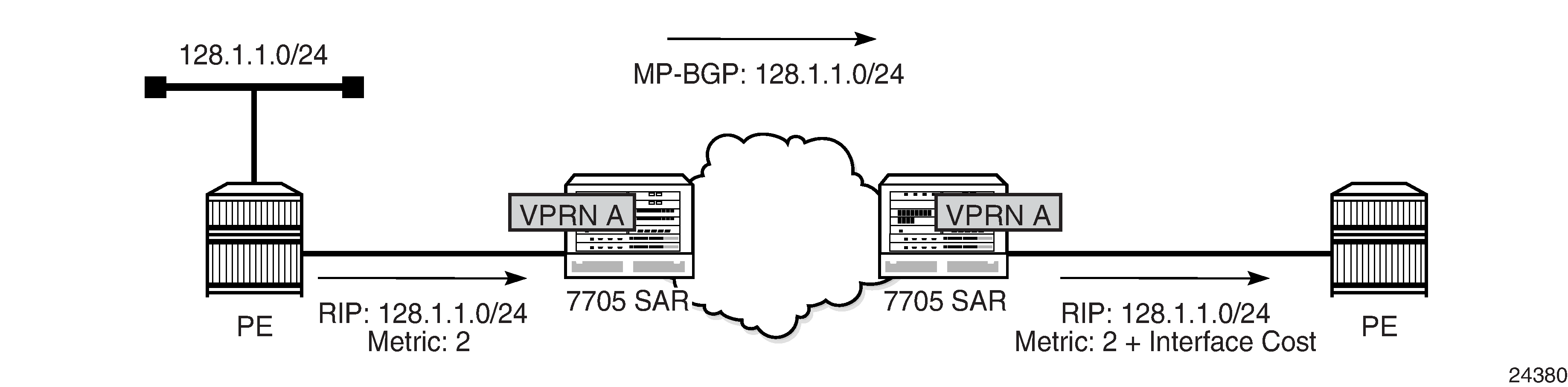
The RIP metric can also be used to exchange routing information between PE routers if a customer network is dual homed to separate PEs. The RIP metric learned from the CE router can be used to choose the best route to the destination subnet. The RIP metric sets the BGP MED attribute, which allows remote PEs to choose the lowest MED and the PE with the lowest advertised RIP metric as the preferred egress point for the VPRN.
Multicast VPN (MVPN)
The two main multicast VPN (MVPN) service implementations are the draft-rosen-vpn-mcast and the Next-Generation Multicast VPN (NG-MVPN).
The 7705 SAR supports NG-MVPNs, which use BGP for customer-multicast (C-multicast) signaling.
The V.35 ports on the 12-port Serial Data Interface card, version 3 do not support Multicast VPN.
The 7705 SAR conforms to the relevant sections of the following RFCs related to MVPNs:
RFC 6388, Label Distribution Protocol Extensions for Point-to-Multipoint and Multipoint-to-Multipoint Label Switched Paths
RFC 6512, Using Multipoint LDP When the Backbone Has No Route to the Root (only as source router)
RFC 6513, Multicast in MPLS/BGP IP VPNs
This section includes information about the following topics:
Multicast in IP-VPN Applications
This section focuses on IP-VPN multicast functionality. As a prerequisite for MVPN, readers should be familiar with the ‟IP Multicast” material in the 7705 SAR Routing Protocols Guide, where multicast protocols (PIM, IGMP, and MLD) are described.
Applications for this feature include enterprise customers implementing a VPRN solution for their WAN networking needs, video delivery systems, and customer applications that include stock-ticker information as well as financial institutions for stock and other types of trading data.
Implementation of next-generation VPRN (NG-VPRN) requires the separation of the provider’s core multicast domain from customer multicast domains, and the customer multicast domains from each other.
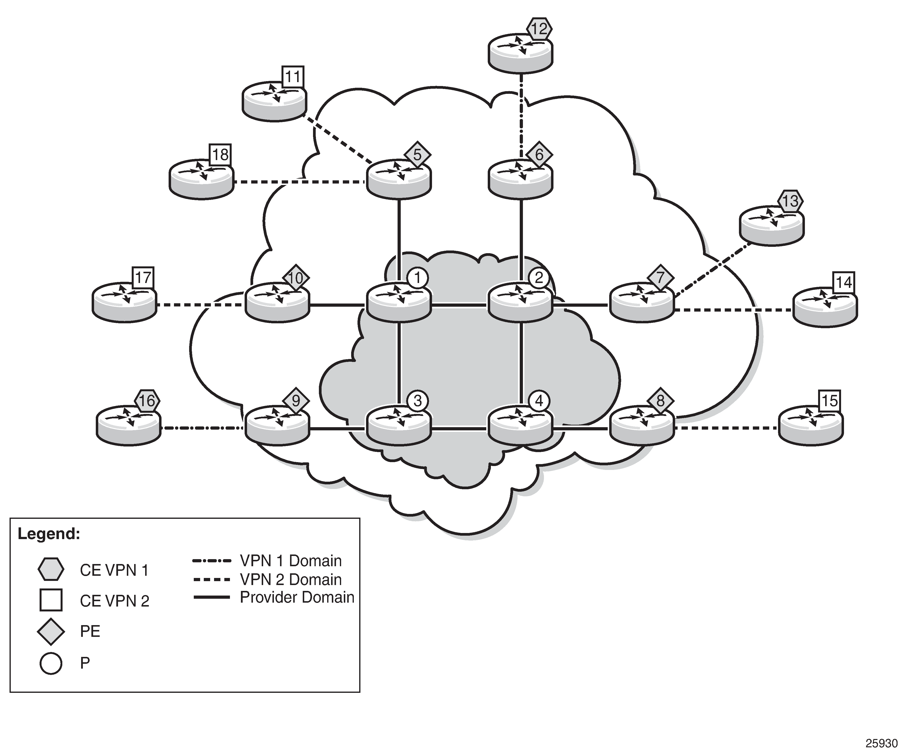
Multicast in an IP-VPN Application shows an example of multicast in an IP-VPN application and shows the following domains:
provider's domain
core routers (1 through 4)
edge routers (5 through 10)
customers’ IP-VPNs, each having their own multicast domain
VPN-1 (CE routers 12, 13, and 16)
VPN-2 (CE routers 11, 14, 15, 17, and 18)
In this VPRN multicast example, VPN-1 data generated by the customer behind router 16 is multicast by PE router 9 to PE routers 6 and 7 for delivery to CE routers 12 and 13, respectively. VPN-2 data generated by the customer behind router 15 is forwarded by PE router 8 to PE routers 5, 7, and 10 for delivery to CE routers 11 and 18, 14, and 17, respectively.
The demarcation points for these domains are in the PEs (routers 5 through 10). The PE routers participate in both the customer multicast domain and the provider multicast domain. The customer CEs are limited to a multicast adjacency with the multicast instance on the PE, where the PE multicast instance is specifically created to support that specific customer IP-VPN. As a result, customers are isolated from the provider core multicast domain and other customer multicast domains, while the provider core routers only participate in the provider multicast domain and are isolated from all customer multicast domains.
The PE for a customer's multicast domain becomes adjacent to the CE routers attached to that PE and to all other PEs that participate in the IP-VPN (customer) multicast domain. The adjacencies are set up by the PE that encapsulates the customer multicast control data and the multicast streams inside the provider's multicast packets. The encapsulated packets are forwarded only to the PE nodes that are attached to the same customer's edge routers as the originating stream and are part of the same customer VPRN. This process prunes the distribution of the multicast control and data traffic to the PEs that participate in the customer's multicast domain.
MVPN Building Blocks
This section includes information about the following topics:
PMSI
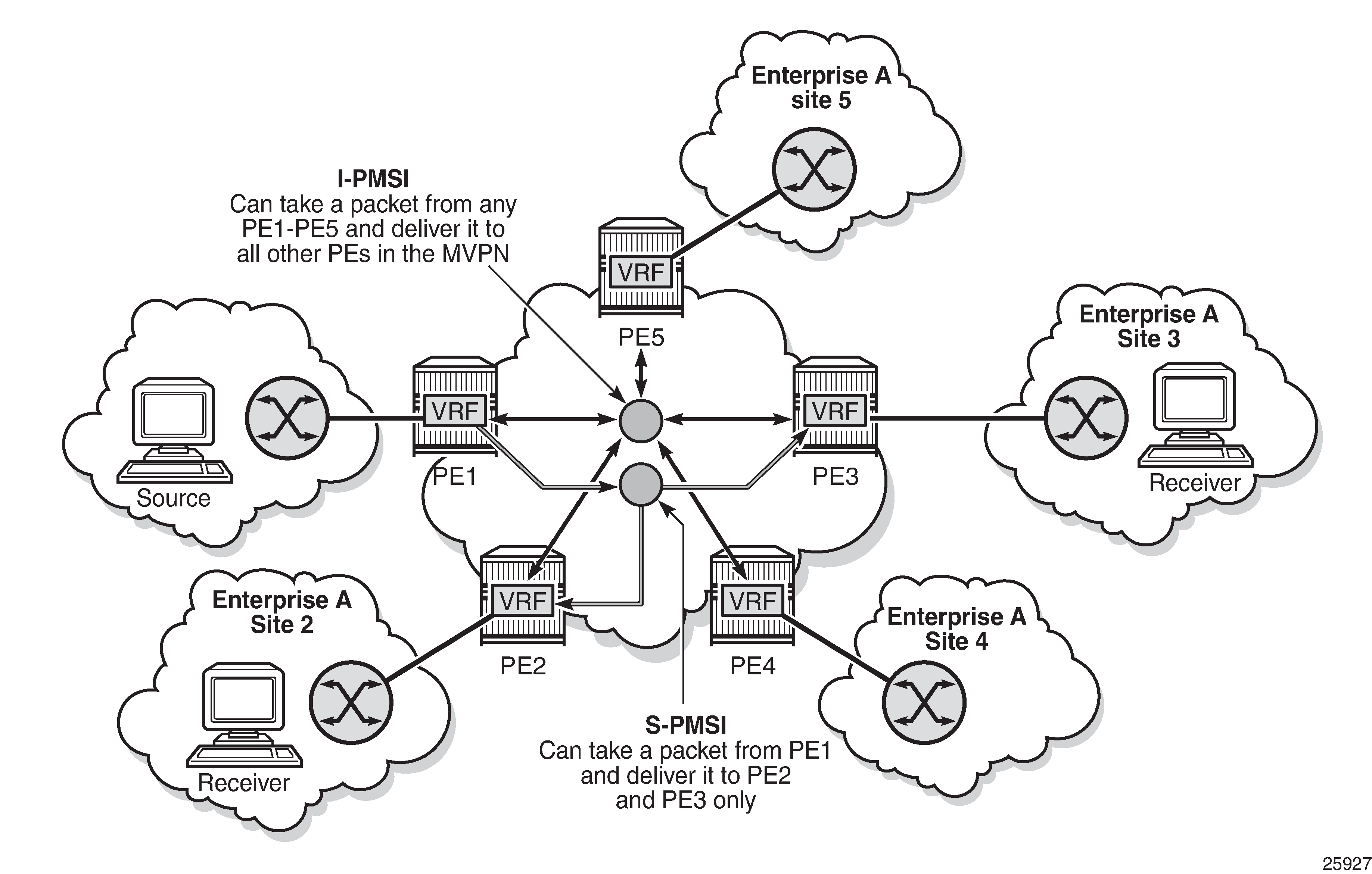
A provider-multicast (P-multicast) service interface (PMSI), described in RFC 6513, refers to an abstract service in the service provider's core network that can take a packet from one PE, belonging to one MVPN, and deliver a copy of the packet to some or all of the other PEs supporting that MVPN.
The most common PMSI uses a multicast distribution tree (MDT). An MDT is a point-to-multipoint traffic path that is instantiated using forwarding table entries that support packet replication. For example, an MDT forwarding entry would specify the incoming interface—where the node expects to receive a packet flowing up or down the MDT—and the set of outgoing interfaces that each receive a copy of the packet. The MDT forwarding state can be set up using an IP multicast signaling protocol such as PIM, or an MPLS protocol such as multicast LDP (mLDP) or RSVP-TE.
The 7705 SAR supports only mLDP PMSI.
This section includes information about the following topics:
PMSI Types
There are two types of PMSIs: inclusive and selective.
An inclusive PMSI (I-PMSI) includes all of the PEs supporting an MVPN. A selective PMSI (S-PMSI) includes a subset of the PEs supporting an MVPN (that is, an S-PMSI is a subset of an I-PMSI). An MVPN can have more than one S-PMSI.
Inclusive PMSIs (I-PMSIs)
An MVPN has one I-PMSI. The I-PMSI carries MVPN-specific control information between the PEs of the MVPN. In the 7705 SAR implementation, by default, all C-multicast flows use the I-PMSI. This minimizes the number of PE router states in the service provider core, but wastes bandwidth because a C-multicast flow on an I-PMSI is delivered to all PEs in the MVPN, even when only a subset of the PEs have receivers for the flow. To reduce wasted bandwidth, a service provider can migrate the C-multicast flow from the I-PMSI to an S-PMSI that includes only the PEs with receivers interested in that (S,G) flow.
On a 7705 SAR, migration of a C-multicast-flow from I-PMSI to S-PMSI can be configured to be initiated automatically by the PE closest to the source of the C-multicast-flow, where the migration trigger is based on the data rate of the flow. Migration occurs when the data rate exceeds the configured threshold.
Selective PMSIs (S-PMSIs)
A selective PMSI is one that includes a subset of the PEs supporting an MVPN. Each MVPN can have zero or more S-PMSIs. As stated above, the transition from I-PMSI to S-PMSI is triggered when the data rate exceeds the user-configured threshold.
I-PMSI versus S-PMSI
I-PMSI and S-PMSI illustrates the difference between an I-PMSI and an S-PMSI. In the figure, the arrowheads indicate send and receive capabilities supported by the PMSI. Two-way arrows imply sender and receiver transmissions, and one-way arrows imply sender-only or receiver-only transmission.
In I-PMSI and S-PMSI, all the VRFs that are part of the MVPN domain receive PDUs from the I-PMSI MDT entries, whether or not the VRFs are configured to receive the PDUs. When the traffic for an (S,G) exceeds the configured data rate threshold, the multicast tree for that (S,G) switches from an I-PMSI to an S-PMSI. Each (S,G) has its own S-PMSI tree built when the threshold for that (S,G) has been exceeded.
Creating a PMSI
The 7705 SAR supports only multicast LDP (mLDP) as the mechanism to build a PMSI tunnel.
When the C-multicast protocol for a leaf node in an MVPN initiates a multicast request, it triggers mLDP to generate an LSP. The C-multicast protocol can be IGMP or PIM, which is configured under the VPRN service.
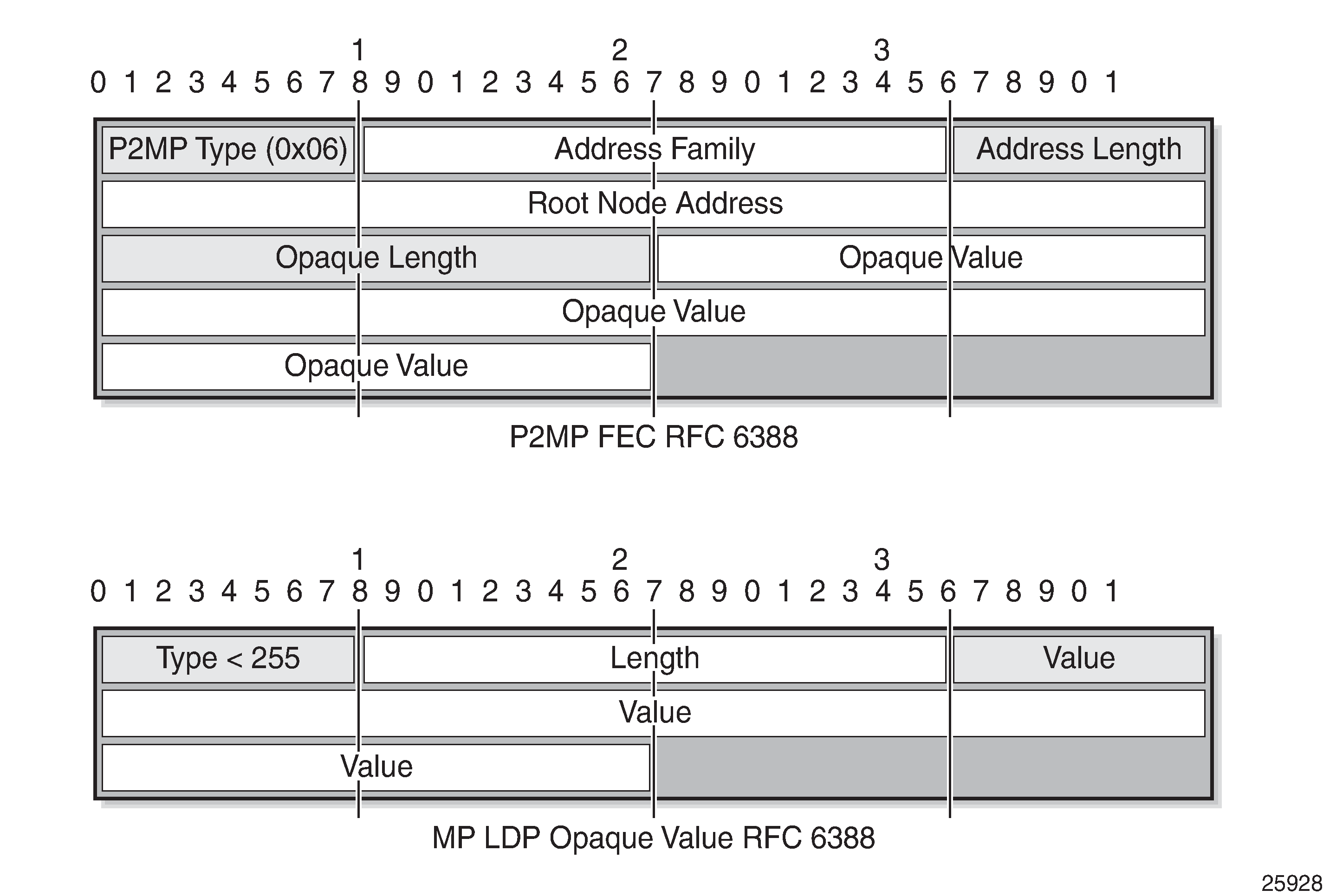
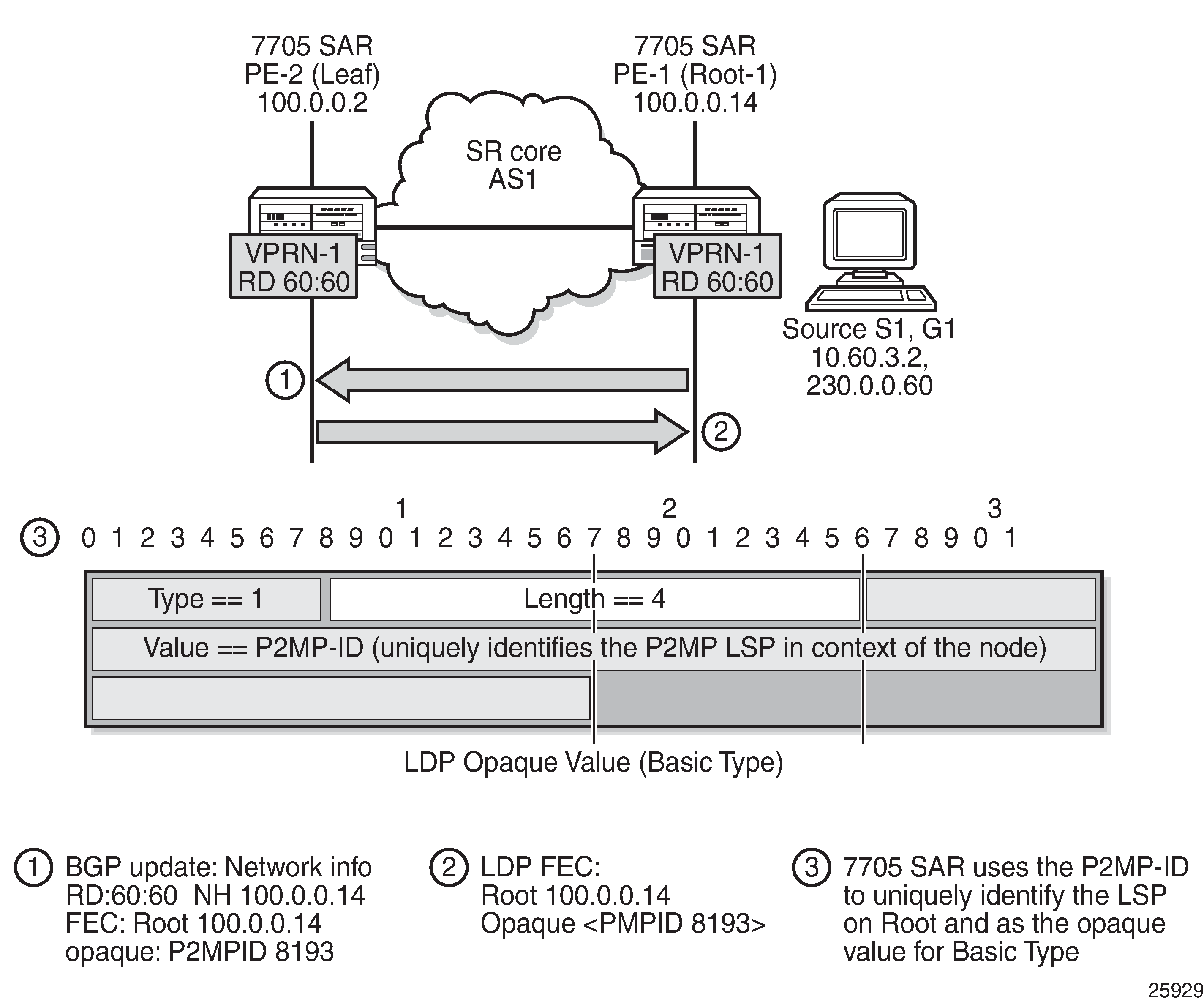
Multicast LDP tries to resolve the source address of (S,G) by looking up the source (S) in the routing table manager (RTM). If there is a resolution, mLDP generates a FEC toward the source (S). The mLDP FEC, as described in RFC 6388, contains the root node’s system IP address and an opaque value. The opaque value contains a point-to-multipoint LSP ID, which uniquely identifies the point-to-multipoint LSP in the context of the root node. P2MP FEC and MP LDP Opaque Value as per RFC 6388 illustrates a point-to-multipoint FEC element and an opaque value.
The P2MP ID is generated on the root node and is advertised to the leaf node via a BGP MVPN address family route update (see BGP MVPN Address Family Updates).
In P2MP FEC and MP LDP Opaque Value as per RFC 6388, the point-to-multipoint FEC element contains of the address of the root of the point-to-multipoint LSP and an opaque value. The opaque value consists of one or more LDP multiprotocol (MP) opaque value elements. The opaque value is unique within the context of the root node, and for the 7705 SAR it is the P2MP ID. The combination of ‟Root Node Address Type”, ‟Root Node Address”, and ‟Opaque Value” uniquely identifies a point-to-multipoint LSP within the MPLS network.
BGP MVPN Address Family Updates shows the following items:
the BGP MVPN address family update (#1), which contains the unique P2MP ID
the LDP FEC (#2), which is generated when the C-multicast IGMP or PIMv4 prompts the LDP to generate the mLDP FEC from the leaf to the root node
the opaque value (basic type) (#3), which is encoded into the mLDP FEC and contains the P2MP ID
MVPN Using BGP Control Plane
To communicate auto-discovery routes and C-multicast signaling, add the mvpn-ipv4 address family to the BGP address family configuration. For more information, see the ‟Configuring BGP Address Families” section in the 7705 SAR Routing Protocols Guide.
The 7705 SAR MVPN implementation is based on NG-VPRN standards and supports the following features:
auto-discovery
PE-PE transmission of C-multicast routing using BGP
IPv4
use of mLDP for S-PMSIs used as PMSIs
inter-AS with direct VRF connect (Option A) and non-segmented mLDP Option C
inter-AS as root router only (Option B)
inter-AS/intra-AS root, ASBR/ABR, leaves and transit router for non-segmented Option C using mLDP
For non-segmented Option C inter-AS/inter-area solution ASBR/ABR cannot be the root of the P2MP tree for mLDP.
Auto-Discovery
Auto-discovery for multicast VPN refers to the process by which a PE with a multicast MVPN service dynamically learns about the other PEs supporting the same MVPN.
The basic auto-discovery function is to discover the identity of all other PEs in the MVPN. This information is essential for setting up the I-PMSI.
Advanced auto-discovery functions are:
discovering the subsets of PEs in the MVPN that are interested in receiving a specific multicast flow
discovering Autonomous System Border Routers (ASBRs) in other ASs that are interested in receiving a specific multicast flow
discovering C-multicast sources that are actively sending traffic across the service provider backbone (in a PMSI)
discovering bindings between multicast flows and PMSIs
The MVPN standards define two different options for MVPN auto-discovery, BGP and PIM. The 7705 SAR only uses MP-BGP for auto-discovery and S-PMSI signaling.
With BGP auto-discovery, MVPN PEs advertise special auto-discovery routes to their peers using multiprotocol extensions to BGP.
Using BGP for auto-discovery does not imply that BGP must be used for C-multicast signaling, nor does it impose any restrictions about the technology used to tunnel MVPN packets between PEs in the service provider backbone.
MVPN Membership Auto-Discovery Using BGP
BGP-based auto-discovery is performed by referring to a multicast VPN address family (for example, mvpn-ipv4). Any PE that attaches to an MVPN must issue a BGP update message containing an NLRI in the address family, along with a specific set of attributes.
The PE router uses route targets to specify an MVPN route import and export policy. The route target may be the same target as the one used for the corresponding unicast VPN, or it may be a different target. For a given MVPN, the PE router can specify separate import route targets for sender sites and receiver sites.
The route distinguisher (RD) that is used for the corresponding unicast VPN can also be used for the MVPN.
In addition, the bindings of C-trees to P-tunnels are discovered using BGP S-PMSI auto-discovery routes.
PE-CE Multicast Protocols and Services
A PE with an MVPN service must learn about the networks and multicast receivers located beyond the CE devices at the MVPN customer site. Typically, IGMP or a PIM protocol is used by the CE to inform the PE that it (the CE) wants to receive a particular multicast flow because it has downstream receivers of that flow. The 7705 SAR supports both IGMP (versions 1, 2, and 3) and PIM Source Specific Multicast (SSM) as the CE-to-PE protocol.
The use of PIM as the CE-to-PE protocol requires that the PE learn about networks beyond the CE so that the PE can appropriately select the correct upstream next hop for sending PIM join and prune messages. The join and prune messages normally follow the reverse path of unicast data traffic and establish the required multicast forwarding state in the PE, CE, and other PIM routers at the customer site. The reachability of networks beyond the CE can be learned through a routing protocol such as OSPF, RIP, or BGP, or it can be configured statically when static routes or multiprotocol BGP are used between the CE and a 7705 SAR PE.
Layer 2 services, such as routed VPLS, can be used to snoop IGMP from the VPLS access interface and translate IGMP to PIM on the PE-CE Layer 3 interface.
The 7705 SAR supports IPv4 PE-CE protocols (for example, IGMP and PIM).
PE-PE Transmission of C-Multicast Routing Using BGP
MVPN C-multicast routing information is exchanged between PEs by using C-multicast routes that are carried by the MVPN NLRI.
PE-PE Multicast Protocols
When a PE gets a request for a multicast flow from a connected CE in an MVPN, it must convey that request to the PE closest to the source of the multicast traffic. In order for a PE to know that another PE is closer to a source, unicast routes must be exchanged between the PEs. This is done by exchanging VPN-IP routes using multiprotocol BGP (MP-BGP). The VPN-IP routes exchanged for this purpose may carry additional information as compared to VPN-IP routes used only for unicast routing. In particular, when NG-MVPN signaling is used, as per RFC 6513, a route that is a candidate for upstream multicast hop (UMH) selection carries two additional BGP extended communities: a source-AS extended community and a VRF route import extended community.
C-multicast signaling is the signaling of joins and prunes from a PE that is connected to a site with receivers of a multicast flow to another PE that is closest to a sender of the multicast flow. Similar to auto-discovery, the MVPN standards allow either PIM or BGP to be used for C-multicast signaling.
The 7705 SAR uses only BGP for C-multicast signaling and multicast route advertisement between PEs.
When BGP is used for C-multicast signaling, a PE announces its desire to join a source C-tree by announcing a special source-join BGP NLRI using BGP multiprotocol extensions. The source-join BGP NLRI has the same AFI and SAFI as the BGP auto-discovery routes (described in RFC 6513). When a PE wants to leave an inter-site source tree, it withdraws the source-join BGP NLRI that it had previously advertised. A PE directs a source-join BGP NLRI to a specific upstream PE—the one it determines to be closest to the source—by including the VRF route import extended community associated with that upstream PE; other PEs may receive the source-join BGP NLRI, but do not import and use it.
Using C-multicast signaling protocols with BGP means that each MVPN PE typically has a small number of BGP sessions (for example, two interior border gateway protocol (IBGP) sessions with two route reflectors in the local AS).
The use of BGP minimizes the control plane load, but may lead to slightly longer join and leave latencies than is the case for the faster recovery of lost BGP messages by the TCP layer underlying the BGP sessions. This is due to the route reflector propagating join and prune messages from downstream PEs to upstream PEs.
PE-PE Multicast Data Transmission
A PMSI can be built on one or more point-to-point, point-to-multipoint, or multipoint-to-multipoint tunnels that carry customer multicast packets transparently through the service provider core network. The MVPN standards provide several technology options for PMSI tunnels:
RSVP-TE LSP (point-to-point and point-to-multipoint)
mLDP LSP (point-to-point, point-to-multipoint, and multipoint-to-multipoint)
GRE tunnel (point-to-point and point-to-multipoint)
Only point-to-multipoint mLDP as a PMSI tunnel is supported.
The 7705 SAR platforms support the following transport options:
I-PMSI – mLDP point-to-multipoint LSPs
S-PMS – mLDP point-to-multipoint LSPs
Provider Tunnel Support
The following provider tunnel features are supported:
I-PMSI
S-PMSI
Topics in this section include:
Point-to-Multipoint I-PMSI and S-PMSI
BGP C-multicast signaling must be enabled for an MVPN instance to use point-to-multipoint mLDP to create an I-PMSI or S-PMSI.
By default, all PE nodes participating in MVPN receive data traffic over an I-PMSI. Optionally, for efficient data traffic distribution, S-PMSIs can be used to send traffic to PE nodes that have at least one active receiver connected.
Only one unique multicast flow is supported over each mLDP point-to-multipoint LSP S-PMSI.
The number of S-PMSIs that can be initiated per MVPN instance is set by the maximum-p2mp-spmsi command. A point-to-multipoint LSP S-PMSI cannot be used for more than one (S,G) stream once the maximum number of S-PMSIs per MVPN is reached. Multicast flows that cannot switch to an S-PMSI remain on the I-PMSI.
Point-to-Multipoint LDP I-PMSI and S-PMSI
A point-to-multipoint LDP LSP as an inclusive or selective provider tunnel is available with BGP NG-MVPN only. A point-to-multipoint LDP LSP is set up dynamically from leaf nodes upon auto-discovery of leaf PE nodes that are participating in multicast VPN. Each LDP I-PMSI or S-PMSI LSP can be used with a single MVPN instance only.
The multicast-traffic command (under config>router>ldp>interface-parameters>interface) must be configured on a per-LDP interface basis to enable a point-to-multipoint LDP setup. Point-to-multipoint LDP must also be configured as an inclusive or selective provider tunnel on a per-MVPN basis. Use the mldp command (under provider-tunnel>inclusive or >selective) to dynamically initiate a point-to-multipoint LDP LSP to leaf PE nodes learned via NG-MVPN auto-discovery signaling. S-PMSI is for efficient data distribution and is optional.
Point-to-Multipoint LSP S-PMSI
NG-MVPN allows the use of a point-to-multipoint LDP LSP as the S-PMSI. An S-PMSI is generated dynamically, based on the user-configured traffic bandwidth threshold for a number of multicast flows. Use the data-threshold command (under provider-tunnel>selective) to set the bandwidth threshold.
In MVPN, the root node PE discovers all the leaf PEs via I-PMSI auto-discovery routes. All multicast PDUs traverse through the I-PMSI until the configured threshold is reached on the root node. When the configured threshold is reached on the root node, the root node signals the desire to switch to an S-PMSI via BGP signaling of the S-PMSI auto-discovery NLRI.
Because of the way that LDP normally works, mLDP point-to-multipoint LSPs are set up (unsolicited) from the leaf PEs towards the root node PE. The leaf PE discovers the root node PE via auto-discovery routes (I-PMSI or S-PMSI). The tunnel identifier carried in the PMSI attribute is used as the point-to-multipoint FEC element.
The tunnel identifier consists of the root node PE address, along with a point-to-multipoint LSP ID. The generic LSP identifier value is automatically generated by the root node PE.
MVPN Sender-only and Receiver-only
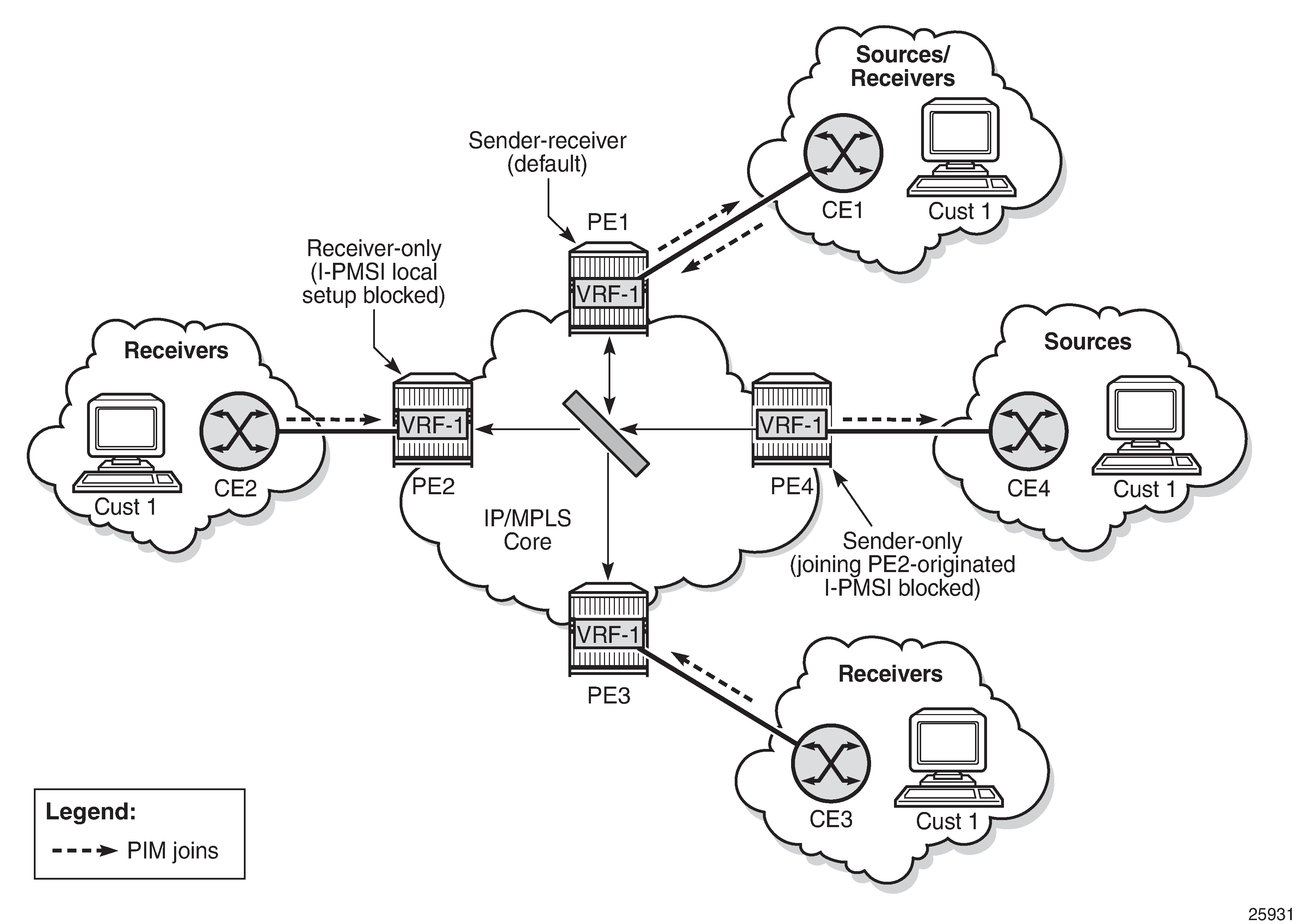
The I-PMSI can be optimized by configuring PE nodes that function as a sender-only or receiver-only node. By default, PE nodes are both sender and receiver nodes (sender-receiver).
In MVPN, by default, if multiple PE nodes form a peering within a common MVPN instance, then each PE node originates a local multicast tree toward the other PE nodes in this MVPN instance. This behavior creates an I-PMSI mesh across all PE nodes in the MVPN. Typically, a VPN has many sites that host multicast receivers only, and has a few sites that host sources only or host both receivers and sources.
MVPN sender-only and receiver-only commands allow the optimization of control-plane and data-plane resources by preventing unnecessary I-PMSI mesh setups when a PE device hosts only multicast sources or only multicast receivers for an MVPN.
For PE nodes that host only multicast sources for a VPN, operators can configure the MVPN to block those PE nodes from joining I-PMSIs that belong to other PEs in the MVPN. For PE nodes that host only multicast receivers for a VPN, operators can block those PE nodes in order to set up a local I-PMSI to other PEs in this MVPN.
MVPN sender-only and receiver-only commands are supported with NG-MVPN using IPv4 LDP provider tunnels for both IPv4 and IPv6 customer multicast. I-PMSI Sender-Receiver, Sender-Only, and Receiver-Only: Optimized I-PMSI Mesh shows a four-site MVPN with sender-only, receiver-only, and sender-receiver (default) sites.
Inter-AS and Intra-AS Solutions
An MVPN service that spans more than one AS is called an inter-AS MVPN. As is the case with unicast-only IP VPN services, there are different approaches for supporting inter-AS MVPNs. Generally, the approaches belong to one of two categories:
all P-tunnels and P-multicast trees start and end on PEs and ASBRs in the same AS
P-tunnels and P-multicast trees extend across multiple ASs
In the first category, the P-tunnels and P-multicast trees start on PEs and ASBRs of an AS, and end on PEs and ASBRs in that same AS (extending no further). In this scenario, C-multicast traffic that must cross an AS boundary is handed off natively between the ASBRs on each side of the AS boundary.
From the perspective of each ASBR, the other ASBR is simply a collection of CEs, each reachable through separate logical connections (for example, VPRN SAPs). In this type of deployment, no auto-discovery signaling is required between the different ASs, and the exchange of C-multicast routes and C-multicast signaling uses the same protocols and procedures as described in PE-CE Multicast Protocols and Services for PE-CE interfaces.
In the second category, P-tunnels and P-multicast trees extend across the boundaries between different ASs. In this scenario, the PMSI extends end-to-end between the PEs of the MVPN, even when those PEs are in different ASs. ASBRs need to exchange auto-discovery information in order to determine whether, for a given MVPN:
the neighbor AS has PEs with sites in the MVPN
the neighbor AS is a transit node on the best path to a remote AS that has sites of the MVPN
If a P-multicast tree is used to transport the PMSI, there are two options for extending the P-tree across multiple ASs:
non-segmented inter-AS MDT
The end-to-end P-tree is end-to-end between all the PEs supporting the MVPN, passing through ASBRs as necessary.
segmented inter-AS MDT (see Inter-AS Option B: Non-Segmented Solution)
The end-to-end P-tree is formed by stitching together a sub-tree from each AS. A sub-tree of an AS connects only the PEs and ASBRs of that AS. A point-to-point tunnel between ASBRs on each side of an AS boundary is typically used to stitch the sub-trees together.
Constructing and using a non-segmented inter-AS MDT is similar to constructing and using an intra-AS MDT, except that BGP auto-discovery messages are propagated by ASBRs across AS boundaries, where the BGP auto-discovery messages are I-PMSI intra-AS auto-discovery routes, despite the reference to intra-AS.
When segmented inter-AS tunnels are used for an NG-MVPN, the ASBRs configured to support that MVPN will originate inter-AS I-PMSI auto-discovery routes for that MVPN toward their external peers after having received intra-AS I-PMSI auto-discovery routes for the MVPN from one or more PEs in their own AS. The inter-AS I-PMSI auto-discovery messages are propagated through all ASs that support the MVPN (that is, through all ASs that have PEs or ASBRs for the MVPN).
When an ASBR receives an inter-AS I-PMSI auto-discovery route, and it is the best route for the NLRI, the ASBR sends a leaf auto-discovery route to the exterior Border Gateway Protocol (EBGP) peer that advertised the route. The leaf auto-discovery route is used to set up a point-to-point, one-hop MPLS LSP that stitches together the P-multicast trees of each AS.
The 7705 SAR supports inter-AS and intra-AS option A.
The 7705 SAR supports non-segmented inter-AS and intra-AS Option C as an ABR or ASBR router or as a leaf router. The 7705 SAR can be part of non-segmented inter-AS and intra-AS with Option B as a root node.
7705 SAR as Source of Non-Segmented Inter-AS or Intra-AS Network
The 7705 SAR can be the source of a non-segmented inter-AS or intra-AS network, as per RFC 6512 and RFC 6513.
Inter-AS Option B: Non-Segmented Solution shows inter-AS option B connectivity via non-segmented mLDP, where the 7705 SAR is acting as a root node. In inter-AS solutions, the leaf and ABR/ASBR nodes need recursive opaque FEC to route the mLDP FEC through the network.
NG-MVPN Non-segmented Inter-AS Solution
This feature allows multicast services to use segmented protocols and span them over multiple autonomous systems (ASs) in the same way as unicast services. Because IP VPN or GRT services span multiple IGP areas or multiple ASs, either for a network designed to deal with scale or as result of commercial acquisitions, operators may require inter-AS VPN (unicast) connectivity. For example, an inter-AS VPN can break the IGP, MPLS and BGP protocols into access segments and core segments, allowing higher scaling of protocols by segmenting them into their own islands. The 7705 SAR allows for a similar provisioning of multicast services and for spanning these services over multiple IGP areas or multiple ASs.
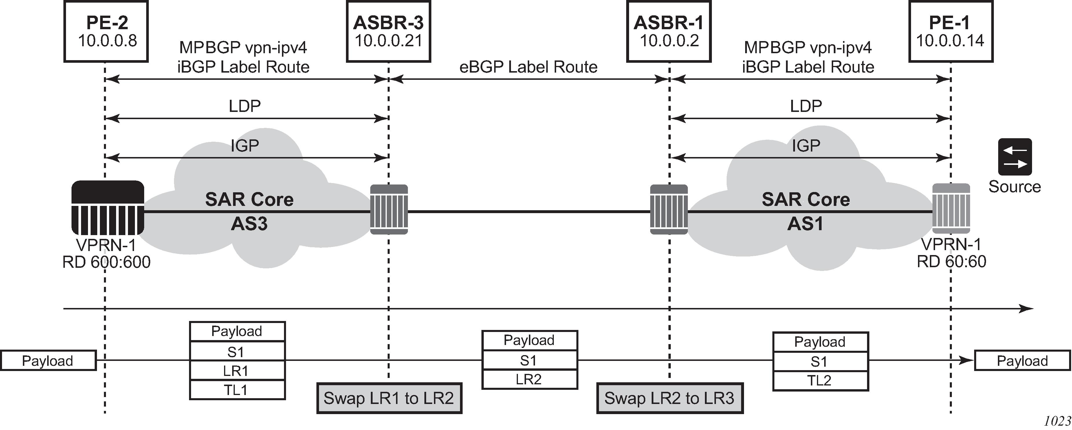
For unicast VPRNs, inter-AS or intra-AS Option C breaks the IGP, BGP and MPLS protocols at ABR routers (for multiple IGP areas) and ASBR routers (for multiple ASs). At ABR and ASBR routers, a stitching mechanism of MPLS transport is required to allow transition from one segment to the next, as shown in Unicast VPN Option C with Segmented MPLS.
In Unicast VPN Option C with Segmented MPLS, the 3107 BGP Label Route (LR) is stitched at ASBR1 and ASBR3. At ASBR1, the LR1 is stitched with LR2, and at ASBR3, the LR2 is stitched with TL2.
Previously, segmenting an LDP MPLS tunnel at ASBRs or ABRs was not possible with NG-MVPN. Therefore, RFC 6512 and 6513 used a non-segmented mechanism to transport the multicast data over P-tunnels end-to-end through ABR and ASBR routers. The signaling of LDP needed to be present and possible between two ABR routers or two ASBR routers in different ASs.
For unicast VPNs, it was usually preferred to only have EBGP between ASBR routers.
The 7705 SAR now has non-segmented intra-AS and inter-AS signaling for NG-MVPN. The non-segmented solution is possible for inter-ASs as Option C.
Non-Segmented Inter-AS VPN Option C Support
The 7705 SAR supports the inter-AS Option C VPN solution. Option C uses recursive opaque type 7 as shown in Recursive Opaque Types.
Opaque Type |
Opaque Name |
RFC |
7705 SAR Use |
|---|---|---|---|
1 |
Basic Type |
RFC 6388 |
VPRN Local AS |
7 |
Recursive Opaque (Basic Type) |
RFC 6512 |
Inter-AS Option C MVPN over mLDP |
In inter-AS Option C, the PEs in two different ASs have their system IP addresses in the RTM, but the intermediate nodes in the remote AS do not have the system IP addresses of the PEs in their RTM. Therefore, for NG-MVPN, a recursive opaque value in mLDP FEC is needed to signal the LSP to the first ASBR in the local AS path.
For inter-AS Option C, on a leaf PE, a route exists to reach the root PE system IP address. Since ASBRs can use BGP unicast routes, recursive FEC processing using BGP unicast routes (not VPN recursive FEC processing using PMSI routes) is required.
I-PMSI and S-PMSI Establishment
I-PMSI and S-PMSI functionality follow RFC 6513 section 8.1.1 and RFC 6512 section 2. The VRR Route Import External community now encodes the VRF instance in the local administrator field.
Option C uses an outer opaque of type 7 and inter opaque of type 1.
Non-segmented mLDP PMSI Establishment (Option C) shows the processing required for I-PMSI and S-PMSI inter-AS establishment.
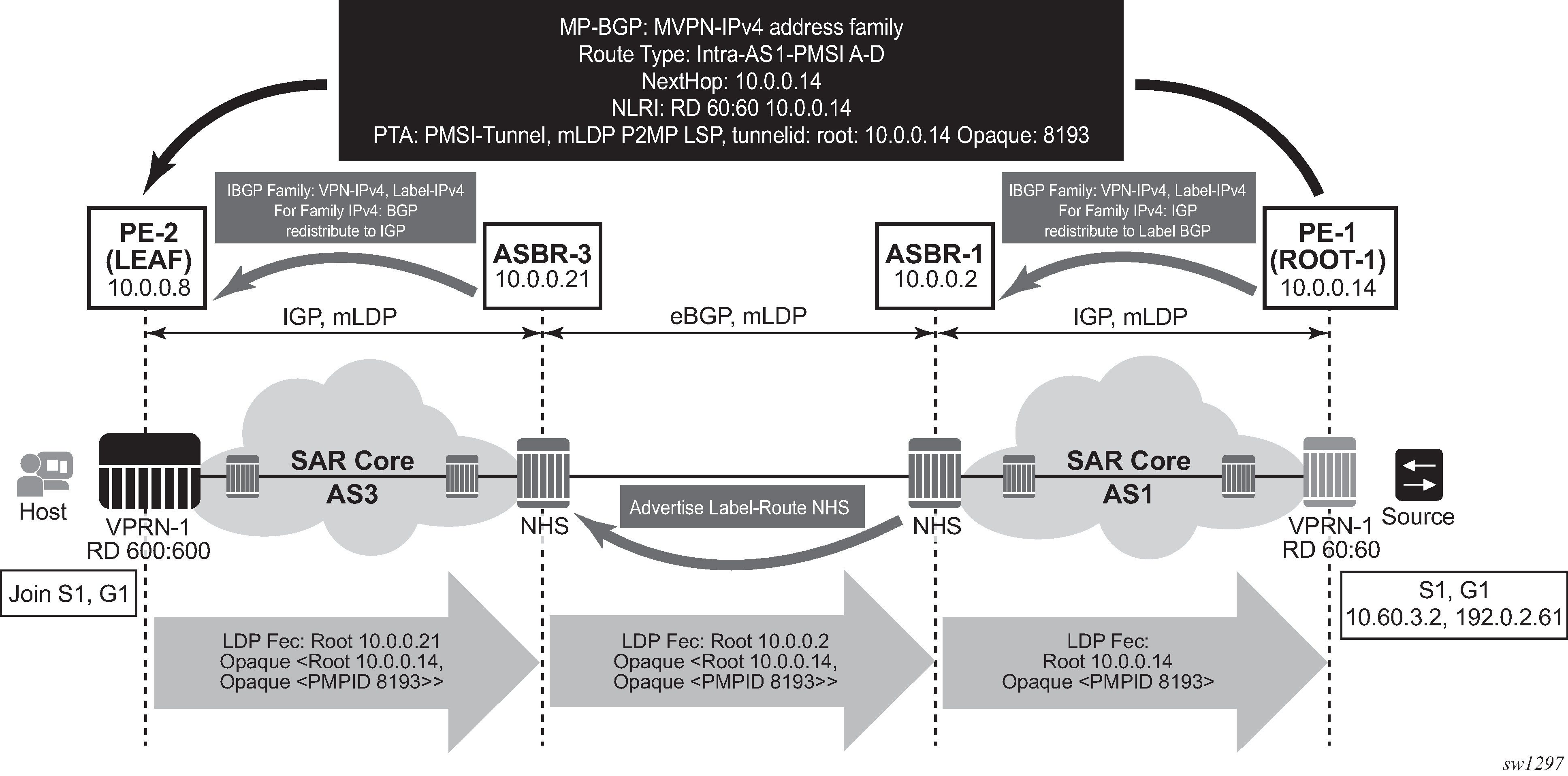
For non-segmented mLDP trees, A-D procedures follow those of the intra-AS model, with the exception that NO EXPORT Community must be excluded; LSP FEC includes mLDP recursive FEC (and not VPN recursive FEC).
For I-PMSI on inter-AS Option C:
A-D routes are not installed by ASBRs and next-hop information is not changed in MVPN A-D routes
BGP labeled routes are used to provide inter-domain connectivity on remote ASBRs
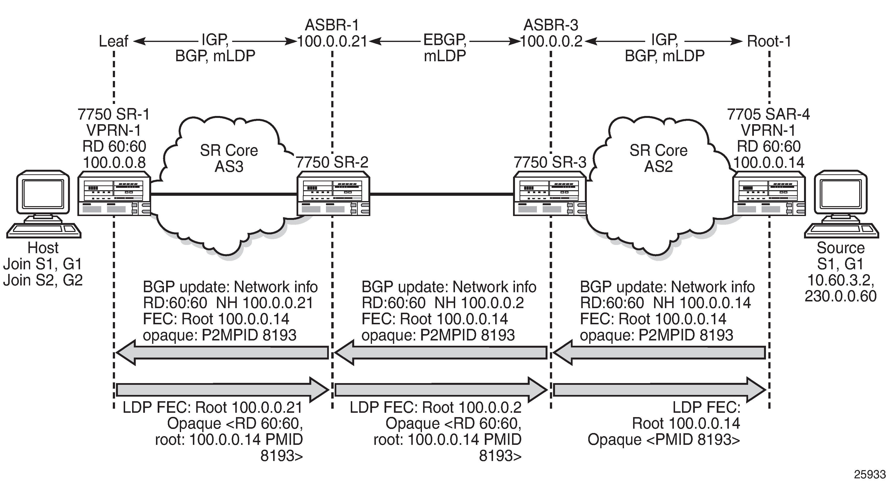
On receipt of an intra-AS I-PMSI A-D route, PE2 resolves PE1’s address (N-H in PMSI route) to a labeled BGP route with a next hop of ASBR3 because PE1 is not known via IGP. PE2 sources an mLDP FEC with a root node of ASBR3 and an opaque value, shown below, containing the information advertised by PE1 in the I-PMSI A-D route.
PE-2 LEAF FEC: {Root = ASBR3, Opaque Value: {Root: ROOT-1, Opaque Value: P2MP-ID xx}}
When the mLDP FEC arrives at ASBR3, it notes that it is the identified root node, and that the opaque value is a recursive opaque value. ASBR3 resolves the root node of the recursive FEC (ROOT-1) to a labeled BGP route with the next hop of ASBR1 because PE-1 is not known via IGP. ASBR3 creates a new mLDP FEC element with a root node of ASBR1 and an opaque value that is the received recursive opaque value.
ASBR3 FEC: {Root: ASBR1, Opaque Value: {Root: ROOT-1, Opaque Value: P2MP-ID xx}}
When the mLDP FEC arrives at ASBR1, it notes that it is the root node and that the opaque value is a recursive opaque value. As PE-1’s address is known to ASBR1 via IGP, no further recursion is required. Regular processing begins, using the received opaque mLDP FEC information.
The functionality as described above for I-PMSI applies to S-PMSI and (C-*, C-*) S-PMSI.
C-multicast Route Processing
C-multicast route processing functionality follows RFC 6513 section 8.1.2 (BGP used for route exchange). The processing is similar to BGP unicast VPN route exchange. Non-segmented mLDP C-multicast Exchange (Option C) shows C-multicast route processing with non-segmented mLDP PMSI details.
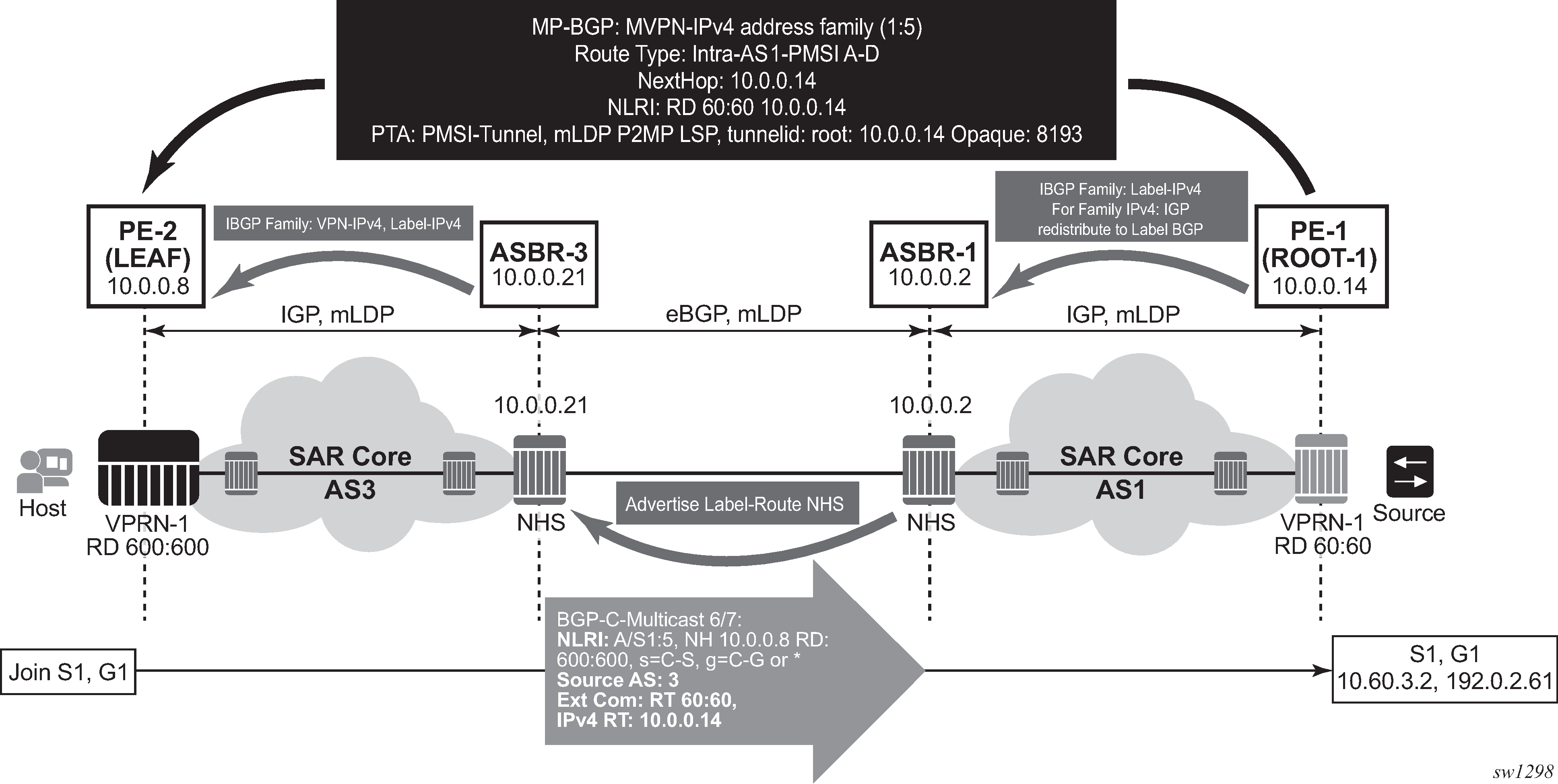
LEAF Node Cavities
The LEAF (PE-2) must have the ROOT-1 system IP address installed in the RTM via BGP. If ROOT-1 is installed in the RTM via IGP, the LEAF will not generate the recursive opaque FEC and ASBR 3 will therefore not process the LDP FEC correctly.
Configuration Example
No configuration is required for Option C on ASBRs.
Policy is required for a root or leaf PE for removing the NO_EXPORT community from MVPN routes, which can be configured using an export policy on the PE.
The following is an example of configuring a policy on PEs to remove the NO_EXPORT community:
*A:Dut-A>config>router>policy-options# info
----------------------------------------------
            community "no-export" members "no-export"
            policy-statement "remNoExport"
                default-action accept
                   community remove "no-export"
                exit
            exit
----------------------------------------------
*A:Dut-A>config>router>policy-options#
The following is an example of configuring the policy under BGP in a global, group, or peer context:
*A:Dut-A>config>router>bgp# info
----------------------------------------------
            vpn-apply-export
            export "remNoExport"
Inter-AS Non-segmented mLDP
See the 7705 SAR MPLS Guide, ‟Inter-AS Non-segmented mLDP” for more information.
ECMP
See the 7705 SAR MPLS Guide, ‟ECMP Support” under ‟Inter-AS Non-segmented mLDP” for more information about ECMP.
Mrinfo and Mtrace
When using mrinfo and mtrace in a Layer 3 VPN context, the configuration for the VPRN should have a loopback address configured that has the same address as the core VPRN instance's system address (that is, the BGP next hop).
For more information, see the ‟IP Multicast Debugging Tools” section in the 7705 SAR OAM and Diagnostics Guide.
Multicast-only Fast Reroute (MoFRR)
The 7705 SAR supports MoFRR in the context of GRT for mLDP. The multicast traffic is duplicated on a primary mLDP multicast tree and a secondary mLDP multicast tree.
For more information, see the ‟Multicast-only Fast Reroute (MoFRR)” section in the 7705 SAR Routing Protocols Guide.
mLDP Point-to-Multipoint Support
The 7705 SAR supports mLDP point-to-multipoint traffic.
For more information, see the ‟LDP Point-to-Multipoint Support” section in the 7705 SAR MPLS Guide.
mLDP Fast Upstream Switchover
This feature allows a downstream LSR of an mLDP FEC to perform a fast switchover in order to source the traffic from another upstream LSR while IGP and LDP are converging due to a failure of the upstream LSR, where the upstream LSR is the primary next hop of the root LSR for the point-to-multipoint FEC.
For more information, see the ‟Multicast LDP Fast Upstream Switchover” section in the 7705 SAR MPLS Guide.
Multicast Source Discovery Protocol
7705 SAR supports Multicast Source Discovery Protocol (MSDP) for MVPNs.
MSDP is a mechanism that allows rendezvous points (RPs) to share information about active sources. When RPs in remote domains hear about the active sources, they can pass on that information to the local receivers and multicast data can be forwarded between the domains. MSDP allows each domain to maintain an independent RP that does not rely on other domains, but it also enables RPs to forward traffic between domains. PIM-SM is used to forward the traffic between the multicast domains.
In addition to supporting MSDP on MVPNs in the VPRN service context, the 7705 SAR supports MSDP in the base router context. For information about MSDP, see the 7705 SAR Routing Protocols Guide.
In an MVPN, a PE node can act as an RP and run the MSDP functionality.
To interconnect multicast domains and to learn about source in other domains, MSDP peering is maintained between RP nodes. MSDP peering occurs over a TCP connection and control information is exchanged between peers to learn about multicast sources in other domains and to distribute information about multicast sources in the local domain.
When MSDP is configured in a service provider MVPN for a given IP VPN customer, at least one of the PEs that are part of that MVPN becomes an MSDP peer to customer-instance RPs. MSDP groups are configured on PEs to limit source-active (SA) advertisements to routers within a group. As the PE RP learns about multicast sources within its domain via PIM-SM, it encapsulates the first data packet in an MSDP SA message and distributes it to all of its peer RP nodes. Based on the RPF check, each peer node sends the control message to other peers to distribute information about the active source. If there is an existing entry for the multicast group, the RP node joins the shortest path tree towards the source.
VPRN Auto-binding Tunnels
The 7705 SAR supports auto-binding for selecting tunnels in the tunnel table manager (TTM) in the following resolution contexts:
resolution of RFC 3107 BGP label route prefix using tunnels to a BGP next hop
resolution of a VPN-IPv4 or VPN-IPv6 prefix to a BGP next hop
The command to auto-bind tunnels is config>service>vprn>auto-bind-tunnel, which has resolution and resolution-filter options.
The user configures the resolution option to enable auto-bind resolution to tunnels in the TTM. If the resolution option is explicitly set to disabled, the auto-binding to the tunnel is removed.
If resolution is set to any, any supported tunnel type in the resolution context will be selected following the TTM preference. The following tunnel types are selected in order of preference: RSVP, LDP, segment routing, and GRE. The user can configure the preference of the segment routing tunnel type in the TTM for a specific IGP instance.
If resolution is set to filter, one or more explicit tunnel types are specified using the resolution-filter option, and only these specified tunnel types will be selected according to the TTM preference.
If a VPRN is configured with auto-bind-tunnel using GRE and the BGP next hop of a VPN route matches a static blackhole route, all traffic matching that VPN route will be blackholed even if the static blackhole route is later removed. Similarly, if a static blackhole route is added after auto-bind-tunnel GRE has been enabled, the blackholing of traffic will not be performed optimally. In general, static blackhole routes that match VPN route next hops should be configured first, before the auto-bind-tunnel GRE command is applied.
An SDP specified by vprn>spoke-sdp is always preferred over auto-bind tunnel, regardless of the tunnel table manager (TTM) preference.
Spoke SDPs
For VPRN service, spoke SDPs can be used only for providing network connectivity between the PE routers.
Spoke SDP Termination to VPRN
This feature enables a customer to exchange traffic between a VLL or VPLS (Layer 2) service and an IES or VPRN (Layer 3) service. Customer premises traffic coming in from a VLL or VPLS service (SAP to spoke SDP) is forwarded over the IP/MPLS network to the IES or VPRN service, and vice versa. Network QoS policies can be applied to the spoke SDP to control traffic forwarding to the Layer 3 service.
In a Layer 3 spoke SDP termination to an IES or VPRN service, where the destination IP address resides within the IES or VPRN network, CE device-generated ARP frames must be processed by the Layer 3 interface. When an ARP frame is received over the spoke SDP at the Layer 3 interface endpoint, the 7705 SAR responds to the ARP frame with its own MAC address. When an ARP request is received from the routed network and the ARP entry for the CE device that is connected to the spoke SDP is not known, the 7705 SAR initiates an ARP frame to resolve the MAC address of the next hop or CE device.
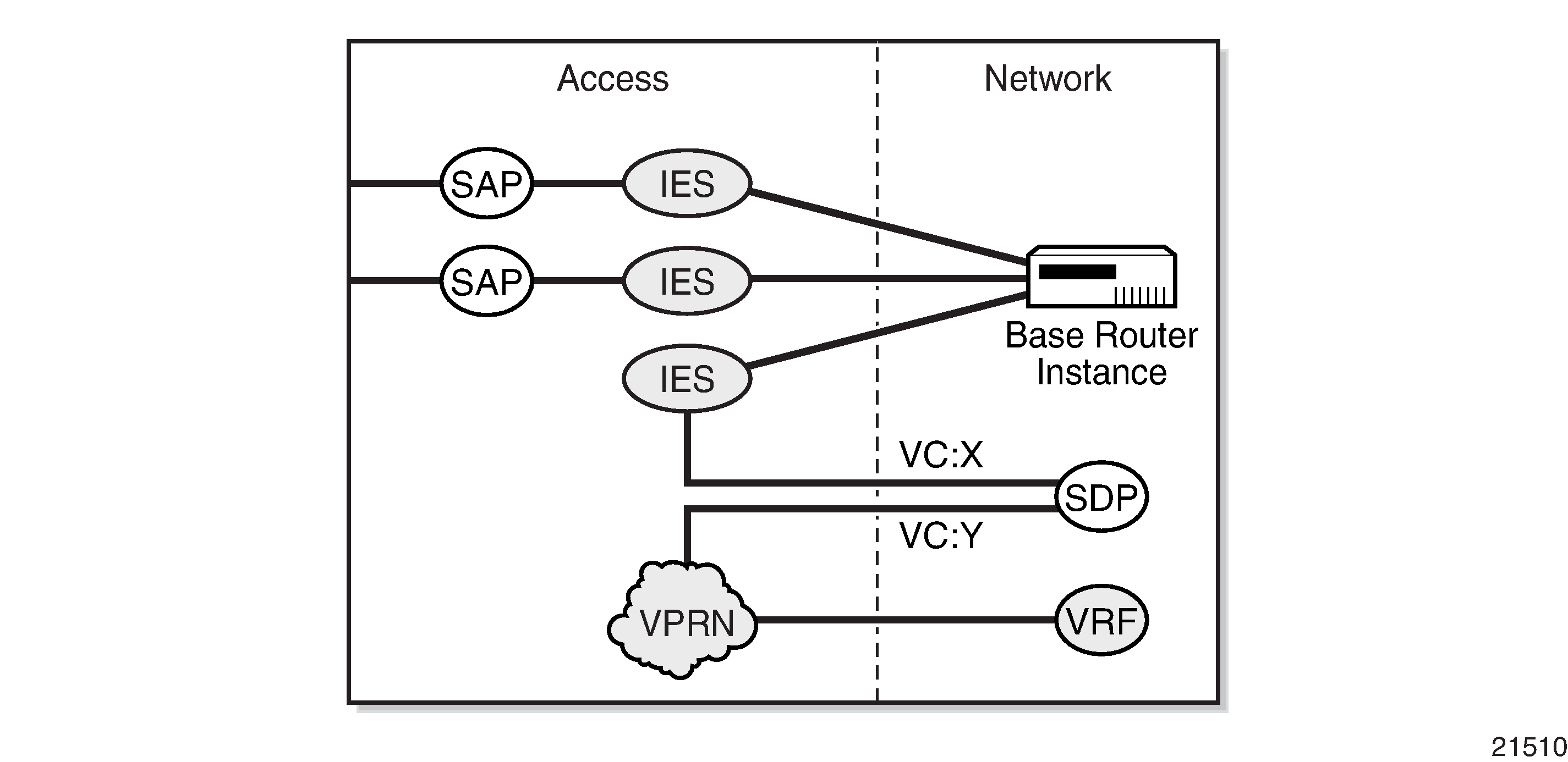
SDP ID and VC Label Service Identifiers (Conceptual View of the Service) shows traffic terminating on a specific IES or VPRN service that is identified by the SDP ID and VC label present in the service packet.
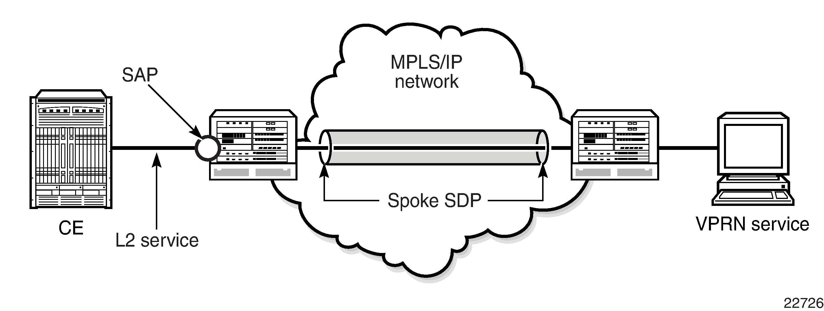
VPRN Spoke SDP Termination shows a spoke SDP terminating directly into a VPRN. In this case, a spoke SDP could be tied to an Epipe or a hierarchical VPLS service. There is no configuration required on the PE connected to the CE.
Ethernet spoke SDP termination for VPRN service is supported over the following network uplinks:
Ethernet network ports (null or dot1q encapsulation)
PPP/MLPPP network ports. For information about PPP/MLPPP ports, see the 7705 SAR Interface Configuration Guide, ‟Access, Network, and Hybrid Ports”
POS ports
Spoke SDP termination for VPRN supports the following:
Ethernet PW to VRF
interface shutdown based on PW standby signaling
spoke SDP ingress IP filtering with filter logging
label withdrawal for spoke SDPs terminated on VPRN
statistics collection
VCCV ping (type 2)
A spoke SDP on a VPRN interface service can be connected to the following entities:
Epipe spoke SDP
Epipe spoke SDP redundancy with standby-signal-master enabled
IES interface
VPRN interface
VPLS spoke SDP
VPLS spoke SDP redundancy with suppress-standby-signaling disabled
There are three scenarios to backhaul traffic from a given site that uses PWs and VPRN on a 7705 SAR.
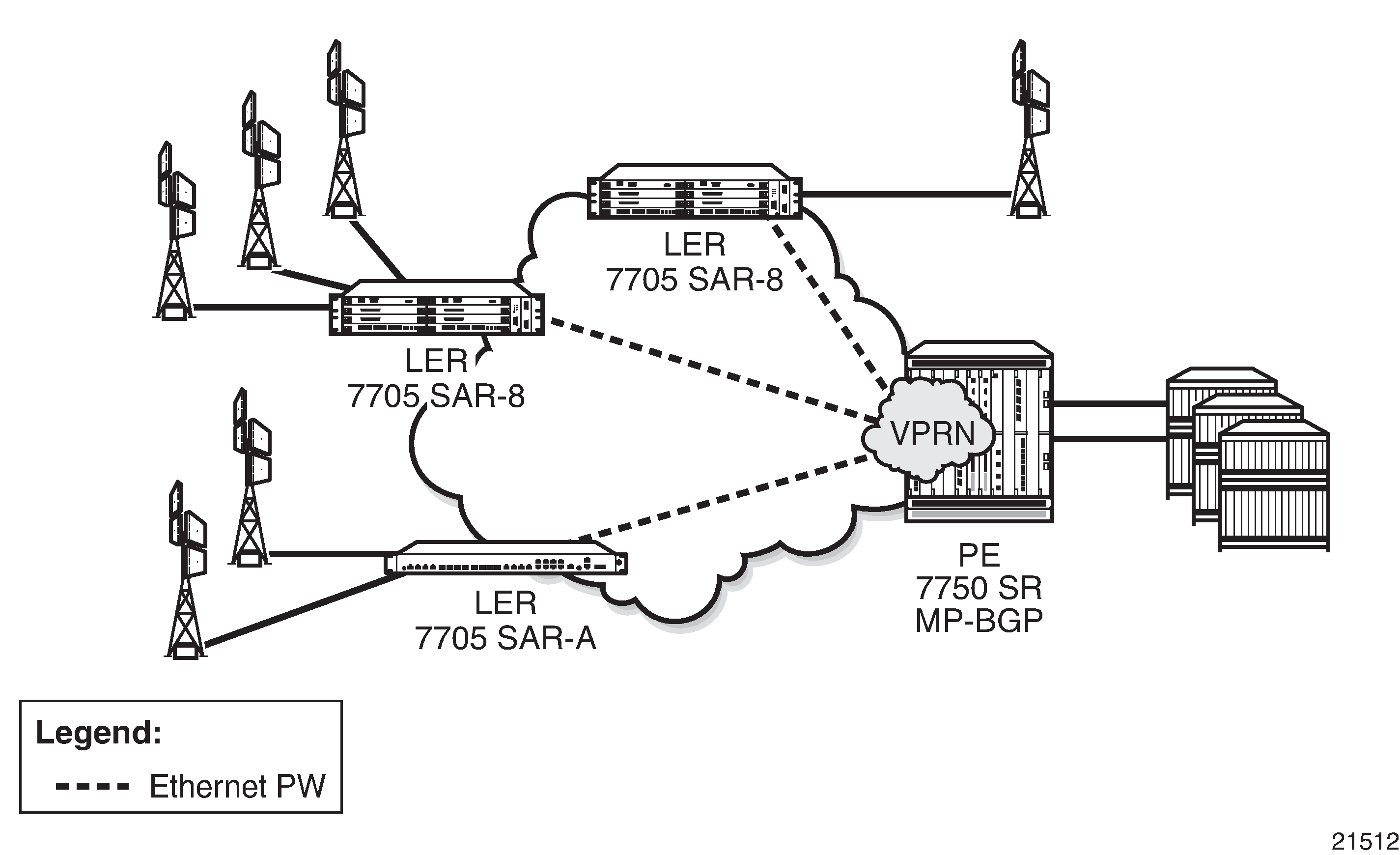
Scenario 1 (Pseudowire-Based Backhaul (Spoke SDP Termination at 7750 SR)): An individual PW is configured on a per-CE device or a per-service basis. For routing services, this PW can be terminated to a VPRN at the 7750 SR end. This scenario offers per-service OAM and redundancy capabilities. Also, because there is no local communication on the remote 7705 SAR, traffic between any two devices connected to the 7705 SAR must traverse through the 7750 SR at the MTSO/CO.
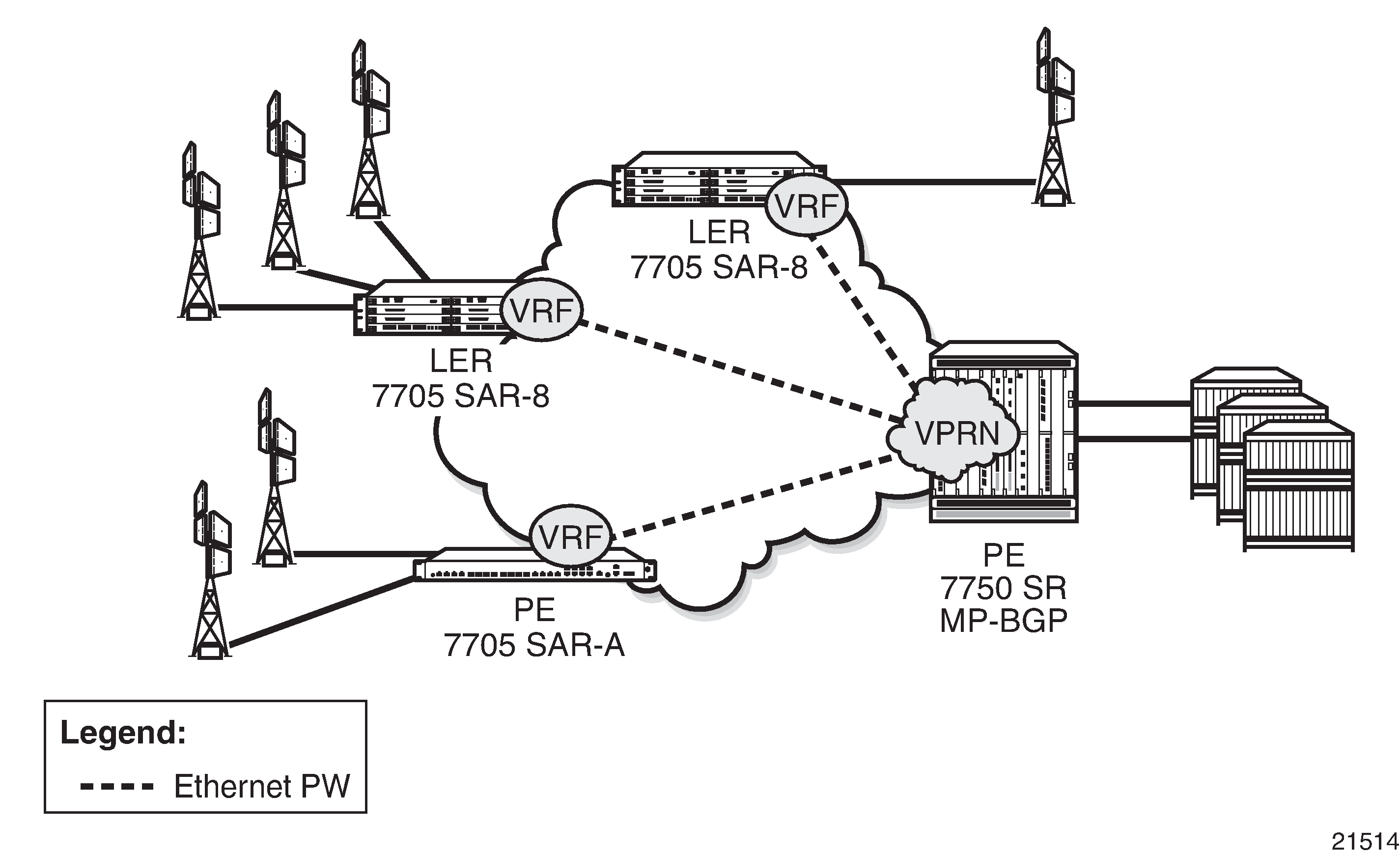
Scenario 2 (VPRN in Mobile Backhaul Application): An MP-BGP-based solution can provide a fully routed scenario.
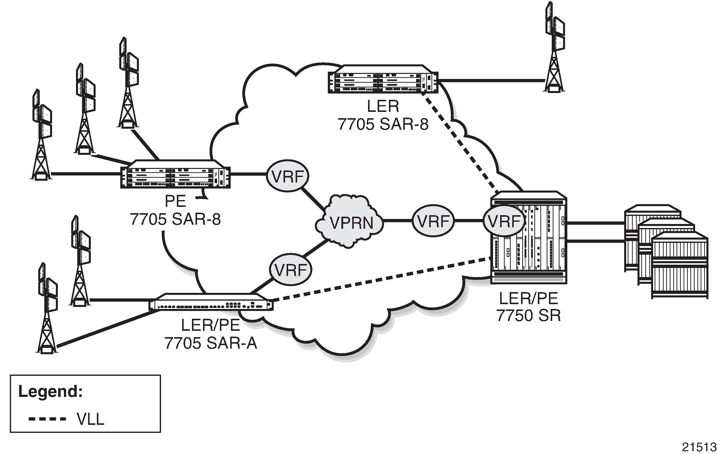
Scenario 3 (Spoke-SDP Termination to VPRN): In the hybrid scenario, IP forwarding among locally connected devices is handled by the 7750 SR directly, but instead of using MP-BGP to backhaul traffic, a PW is used to backhaul traffic to the MTSO/CO 7750 SR or possibly to a 7705 SAR node.
IPv6 on Virtual Private Edge Router
The IPv6 on Virtual Private Edge Router (6VPE) feature allows customers that are migrating from an IPv4 to an IPv6 environment to use their existing IPv4 core infrastructure for transporting IPv6 traffic. Customers can migrate their access network to IPv6, including the eNodeBs, and keep the IPv4 core. The IPv4 core can be used for transporting eNodeB IPv6 traffic over MPLS or GRE tunnels. See IPv6 over IPv4 LAN-to-LAN IPSec Tunnels for a description of how the 6VPE functionality is achieved.
-
The 6VPE feature is not supported on the 16-port T1/E1 ASAP Adapter card or 32-port T1/E1 ASAP Adapter card. This applies to both the access side (VPRN interfaces) and network side (MPLS/GRE tunnels).
-
On the network side, 6VPE is not supported on DS3/OC3 network interfaces, but is supported on SAR-A, SAR-M, SAR-H, and SAR-X T1/E1 ASAP network interfaces.
-
On the access side, 6VPE (VPRN SAP interfaces) is not supported on any T1/E1 ASAP adapter cards/blocks or on the 12-port Serial Data Interface card, version 3 (v.35 ports). VPRN spoke-SDP interfaces (spoke-SDP termination) are supported on SAR-A, SAR-M, SAR-H, and SAR-X T1/E1 ASAP blocks but not on T1/E1 adapter cards.
The classification of packets on a 6VPE access network is based on a customer packet Transaction Code (TC) field. The TC field is one byte long, but only the first six bits are used for the classification process. The use of six bits offers 64 different classes. The marking of the network outer tunnel DSCP/EXP bits is based on this access classification.
The supported protocols for 6VPE are listed in IPv4 and IPv6 GRT-Supported Management Protocols. The Access Control Lists for 6VPE are provided by 6VPE Access Control List, SAP , 6VPE Access Control List, SDP , and 6VPE Access Control List, r-VPLS Override .
Service |
IngV4 |
IngV6 |
IngMac |
EgrV4 |
EgrV6 |
EgrMac |
|---|---|---|---|---|---|---|
Network |
Yes |
Yes |
No |
Yes |
Yes |
No |
Epipe |
Yes |
No |
No |
No |
No |
No |
IES |
Yes |
Yes |
No |
Yes |
Yes |
No |
Ipipe |
Yes |
No |
No |
No |
No |
No |
VPLS |
Yes |
Yes |
Yes |
Yes |
Yes |
No |
VPRN |
Yes |
Yes |
No |
Yes |
Yes |
No |
Service |
IngV4 |
IngV6 |
IngMac |
EgrV4 |
EgrV6 |
EgrMac |
|---|---|---|---|---|---|---|
Epipe |
No |
No |
No |
No |
No |
No |
IES |
Yes |
No |
No |
No |
No |
No |
Ipipe |
No |
No |
No |
No |
No |
No |
VPLS |
Yes |
Yes |
Yes |
No |
No |
No |
VPRN |
Yes |
Yes |
No |
No |
No |
No |
Service |
Ingress Override-v4 |
Ingress Override-v6 |
|---|---|---|
IES |
Yes |
Yes |
VPRN |
Yes |
Yes |
IPv6 over IPv4 LAN-to-LAN IPSec Tunnels
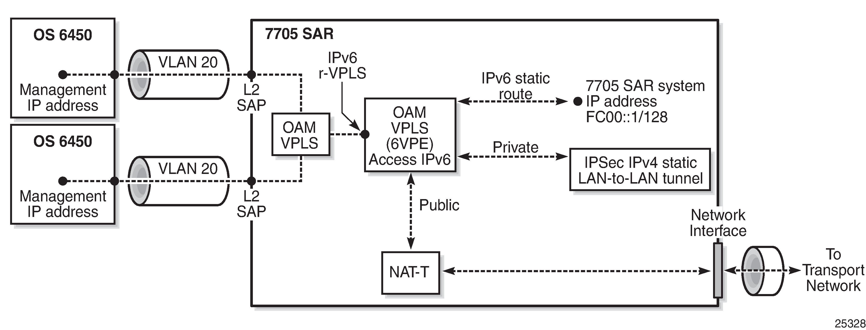
In order to support the 6VPE functionality described in IPv6 on Virtual Private Edge Router, access (customer) IPv6 traffic is aggregated using a service VPRN and encrypted via an IPSec IPv4 static LAN-to-LAN tunnel, as shown in Access IPv6 Traffic Aggregation and Encryption. BGPv4 or BGPv6 can be configured over the IPSec IPv4 static LAN-to-LAN tunnel with an IPv6 address family to advertise the IPv6 VPRN routes to the peer VPRN.
The management IP addresses of all customer switches are migrated to IPv6. The system IP address of the 7705 SAR is configured as an IPv6 address and also migrated to IPv6. The OAM customer traffic is aggregated via an r-VPLS (IPv6 r-VPLS) into a 6VPE OAM VPRN. An IPv6 static route carries the IPv6 OAM traffic to an IPv4 static LAN-to-LAN tunnel, where the traffic is encrypted and encapsulated in an IPSec IPv4 transport tunnel. The IPSec IPv4 transport tunnel uses a NAT-to-single public IP address method, that is, NAT-T.
Bandwidth Optimization for Low-speed Links
The 7705 SAR can be used in deployments where the uplink bandwidth capacity and requirements are considerably less than if the router is used for fixed or mobile backhaul applications. For example, the 7705 SAR can be used to direct traffic from multiple individual homes for applications such as smart meter aggregation or relay connectivity. Connecting to end systems such as smart meters or relays requires uplink bandwidth capacity in terms of hundreds of kilobits per second, rather than hundreds of megabits per second.
The 7705 SAR is optimized to operate in environments with megabits per second of uplink capacity for network operations. Therefore, many of the software timers are designed to ensure the fastest possible detection of failures, without considering bandwidth limitations. In deployments with very low bandwidth constraints, the system must also be optimized for effective operation of the routers without any interruption to mission-critical customer traffic. This can be achieved by:
minimizing head-of-line (HoL) blocking by supporting a lower MTU
redirecting self-generated traffic (SGT) to data queues (see the 7705 SAR Quality of Service Guide, ‟SGT Redirection”, for information)
One way to optimize operation in lower-bandwidth applications is to minimize HoL blocking caused by large packets. HoL blocking occurs when transmission of a large non-mission-critical packet delays a mission-critical packet beyond acceptable limits. The propagation delay of large packets over a slow link is fairly significant. For example, the propagation delay when transmitting a 1500-byte packet over a 100 kb/s link is 120 ms. If a mission-critical packet is queued immediately after the first bit of a non-mission-critical 1500-byte packet begins transmission, the mission-critical packet must wait 120 ms before the uplink is available again.
To minimize HoL blocking, the 7705 SAR now supports a lower MTU of 128 bytes (from the original 512-byte minimum) so that large IP packets can be fragmented into 128-byte chunks. In the preceding example, transmitting a 128-byte packet over a 100 kb/s link will only delay the next packet by 10.24 ms.
This lower MTU is supported on IES and VPRN interfaces (access interfaces) and on network interfaces. The IP MTU is derived from the port MTU, unless specifically configured with the ip-mtu command. This command is supported on access interfaces only.
The following must be considered when using a lower IP MTU:
applicability – the lower IP MTU is only applicable for IP forwarded traffic and cannot be applied to pseudowire or VPLS traffic
reassembly – the far-end/destination node must reassemble the packet before it can process the data, which may impact the performance of the end system and/or may require different hardware to perform the reassembly
extra overhead – each fragment must have an IPv4 header so that all fragments of the packet can be forwarded to the destination. Care must be taken to ensure that the extra IP overhead for each fragment does not offset the gain achieved by using the lower MTU. As an example, for a 128-byte packet, the IPv4 header, which is 20 bytes in length, constitutes approximately 15% of the total packet size.
Lower IP MTU applies to IPv4 applications only. As per RFC 2640, IPv6 interfaces or dual-stack interfaces should not be configured to a value lower than 1280 bytes.
Lower IP MTU is supported only on Ethernet encapsulated ports.
Most routing and signaling protocols, such as OSPF, IS-IS, and RSVP-TE, cannot be supported with port MTUs lower than 512 bytes due to the protocol layer requirements and restrictions.
Special care must be taken with routing protocols that use TCP, such as BGP and LDP. The minimum TCP MSS value supported on the 7705 SAR is 384 bytes; therefore, these protocols should only be enabled on links that can transport 384-byte IP packets without fragmentation. If there is a mismatch in TCP MSS in the network, this mismatch can potentially cause severe network performance issues due to the overhead caused by fragmentation and retransmissions, it can cause multi-vendor interoperability issues, and it can potentially cause the protocols to continuously flap.
Not all OAM diagnostics are supported with lower port MTUs. Detailed information is provided in OAM Diagnostics Restrictions with Lower IP MTU.
OAM Diagnostics Restrictions with Lower IP MTU
OAM tests require a minimum network port MTU in order to run; this value depends on the test. If the port MTU is set to a value lower than the minimum requirement, the test will fail.
If the port MTU is set to a value that meets the minimum requirement, the packet size parameter can be configured for the test (for example, oam sdp-ping 1 size 102).
If the size parameter is not specified, the system builds the packet based on the default payload size. If the size parameter is configured and is greater than the default payload size, padding bytes are added to equal the configured value.
The packet size is dependent on the port MTU value; that is, if the minimum port MTU value is used, there are restrictions on the packet size. If the configured size is greater than the maximum value supported with the minimum port MTU, the test will fail.
Port MTU Requirements for OAM Diagnostics (GRE Tunnels) and Port MTU Requirements for OAM Diagnostics (LDP Tunnels) list the minimum port MTU required for each OAM test and the maximum size of the OAM packet that can be configured when the minimum port MTU is used, based on SDP tunnel type.
SDP Type: GRE |
||
|---|---|---|
Test Type |
Minimum Network Port MTU Requirement over Ethernet Dot1q Encapsulation (Bytes) |
OAM Test Size Range (Bytes) |
sdp-ping |
128 |
72 to 82 |
svc-ping |
196 |
N/A1 |
vccv-ping |
143 |
1 to 93 |
vccv-trace |
143 |
1 to 93 |
vprn-ping |
182 |
1 to 136 |
vprn-trace |
302 |
1 to 256 |
mac-ping |
188 |
1 to 142 |
mac-trace |
240 |
1 to 194 |
cpe-ping |
186 |
N/A1 |
Note:
Size is not configurable
SDP Type: LDP |
||
|---|---|---|
Test Type |
Minimum Network Port MTU Requirement over Ethernet Dot1q Encapsulation (Bytes) |
OAM Test Size Range (Bytes) |
lsp-ping |
128 |
1 to 106 |
lsp-trace |
128 |
1 to 104 |
sdp-ping |
128 |
72 to 102 |
svc-ping |
176 |
N/A1 |
vccv-ping |
128 |
1 to 98 |
vccv-trace |
128 |
1 to 98 |
vprn-ping |
182 |
1 to 156 |
vprn-trace |
302 |
1 to 276 |
mac-ping |
168 |
1 to 142 |
mac-trace |
220 |
1 to 194 |
cpe-ping |
166 |
N/A1 |
Note:
Size is not configurable
For information about OAM diagnostics, see the 7705 SAR OAM and Diagnostics Guide.
Support for NTP
On the 7705 SAR, communication with external NTP clocks over VPRNs is supported for external NTP servers and peers and for external NTP clients.
Communication with external servers and peers is controlled using the same commands as those used in the base routing context; see the 7705 SAR Basic System Configuration Guide, ‟System Time Commands”, for information. Communication with external clients is controlled using commands in the VPRN context. Support for external clients can be as a unicast or a broadcast service. In addition, authentication keys for external clients are configurable on a per-VPRN basis.