VPRN Service Overview
Topics in this section include:
RFC 2547bis, an extension of RFC 2547, details a method of distributing routing information and forwarding data to provide a Layer 3 Virtual Private Network (VPN) service to end customers.
Each Virtual Private Routed Network (VPRN) consists of a set of customer sites connected to one or more PE routers. Each associated PE router maintains a separate IP forwarding table for each VPRN. Additionally, the PE routers exchange the routing information configured or learned from all customer sites via MP-BGP peering. Each route exchanged via the MP-BGP protocol includes a route distinguisher (RD), which identifies the VPRN association.
The service provider uses BGP to exchange the routes of a particular VPN among the PE routers that are attached to that VPN. This is done in a way that ensures that routes from different VPNs remain distinct and separate, even if two VPNs have an overlapping address space. Within a particular VPN, the PE routers distribute route information from and to the CE routers. Since the CE routers do not peer with each other, there is no overlay visible to the VPN routing algorithm.
When BGP distributes a VPN route, it also distributes an MPLS label for that route. On an individual 7705 SAR, a single label is assigned to (advertised for) all routes in a VPN. A VRF lookup is used to determine the egress interface for a packet.
Before a customer data packet travels across the service provider’s backbone network, it is encapsulated with the MPLS label that corresponds, in the customer’s VPN, to the route that best matches the packet’s destination address. That label (called the inner label) is the label that was advertised from the destination 7705 SAR, as described in the previous paragraph. The MPLS packet is further encapsulated with either another MPLS label or GRE tunnel header, so that it gets tunneled across the backbone to the correct PE router.
Each route exchanged by the MP-BGP protocol includes a route distinguisher (RD), which identifies its VPRN association. Thus, the backbone core routers do not need to know the VPN routes.
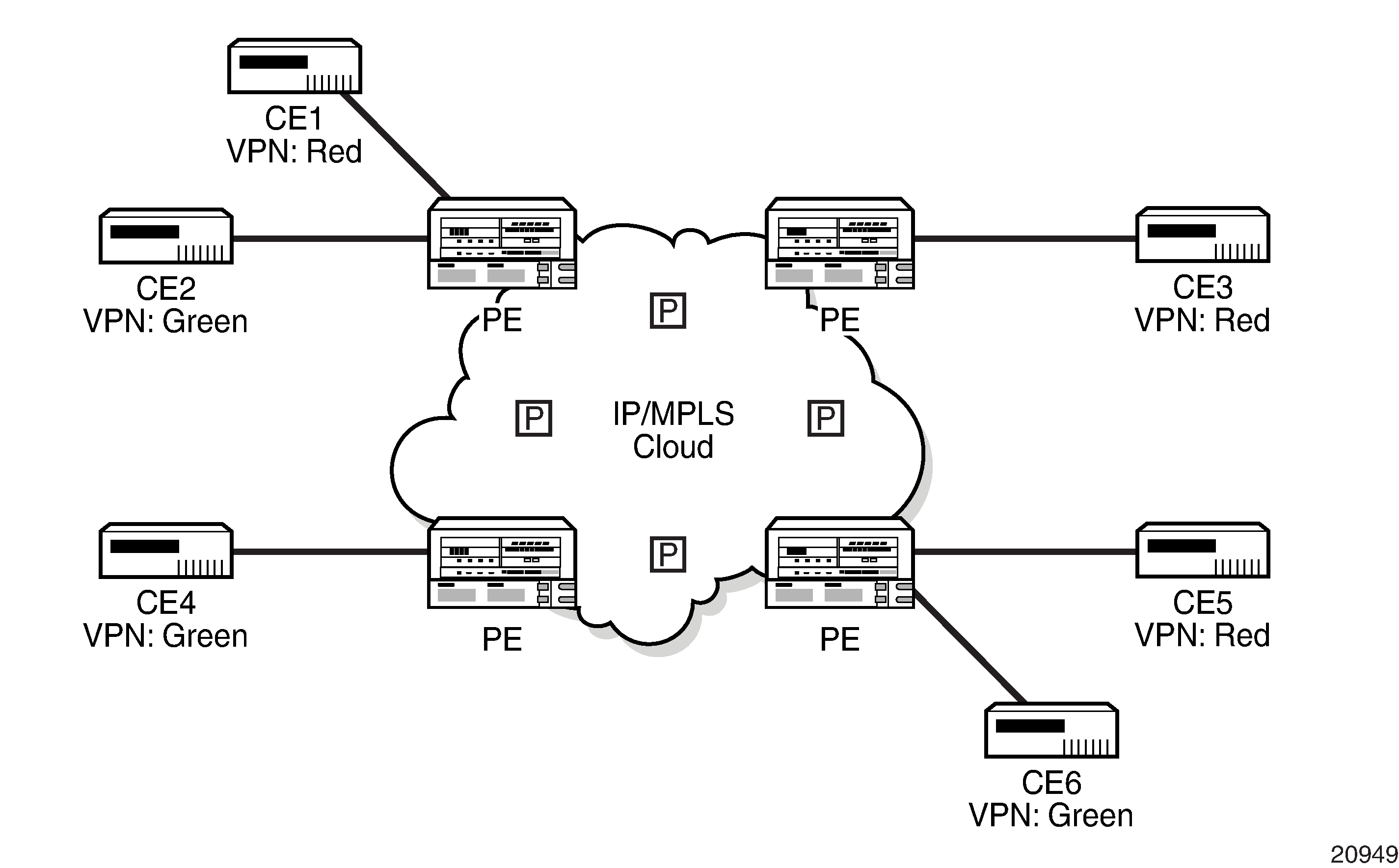
Virtual Private Routed Network shows an example of a VPRN network diagram, showing two VPNs (labeled ‟Red” and ‟Green”) attached to PEs. The core routers are labeled ‟P”.
VPRN is supported on the following:
any DS1/E1 port on the 4-port OC3/STM1 / 1-port OC12/STM4 Adapter card
the 16-port T1/E1 ASAP Adapter card
the 32-port T1/E1 ASAP Adapter card
the Packet Microwave Adapter card
any V.35 port on the 12-port Serial Data Interface card, version 3
any T1/E1 port on the 7705 SAR-M
any T1/E1 port on the 7705 SAR-A
any T1/E1 port on the 4-port T1/E1 and RS-232 Combination module
any port on the 6-port Ethernet 10Gbps Adapter card
any port on the 8-port Gigabit Ethernet Adapter card
any port on the 10-port 1GigE/1-port 10GigE X-Adapter card (10-port 1GigE mode)
any port on the 4-port SAR-H Fast Ethernet module
any port on the 6-port SAR-M Ethernet module
any port on the 7705 SAR-A
any port on the 7705 SAR-X
any Ethernet port on the 7705 SAR-M
any Ethernet port on the 7705 SAR-Ax
any Ethernet port on the 7705 SAR-Wx
any Ethernet or T1/E1 port on the 7705 SAR-H
any Ethernet port on the 7705 SAR-Hc
Ports must be in access mode.
Routing Prerequisites
RFC 2547bis requires the following features:
multiprotocol extensions
LDP support
extended BGP community support
BGP capability negotiation
parameters defined in RFC 2918, BGP Route Refresh, and RFC 2796, Route Reflector
a 4-byte autonomous system (AS) number
Tunneling protocol requirements are as follows:
RFC 2547bis, BGP/MPLS VPNs, recommends implementing Label Distribution Protocol (LDP) to set up a full mesh of LSPs based on the IGP
MPLS RSVP-TE tunnels can be used instead of LDP
BGP route tunnels can be used as defined in RFC 3107
alternatively, Generic Routing Encapsulation (GRE) tunnels can also be used
BGP Support
BGP is used with BGP extensions, as mentioned in Routing Prerequisites, to distribute VPRN routing information across the service provider’s network.
BGP was initially designed to distribute IPv4 routing information. Therefore, multiprotocol extensions and the use of a VPN-IPv4 address were created to extend the ability of BGP to carry overlapping routing information. A VPN-IPv4 address is a 12-byte value consisting of the 8-byte route distinguisher (RD) and the 4-byte IPv4 IP address prefix. The RD must be unique within the scope of the VPRN. This allows the IP address prefixes within different VRFs to overlap. In addition, 128-bit VPN-IPv6 addresses extend the capability to distribute VPRN routing information.
BGP route tunnels can be used to distribute label mapping information for a particular route, as defined in RFC 3107. For more information about BGP route tunnels, see the 7705 SAR Routing Protocols Guide, ‟BGP Route Tunnel”.
VPRN BGP is configured through the config>service>vprn>bgp context. Global BGP is configured through the config>router>bgp context.
BGP Fast Reroute with Prefix-Independent Convergence in a VPRN
BGP Fast Reroute (FRR) creates an alternate path to support fast rerouting of BGP traffic around failed or unreachable next hops. When BGP FRR is enabled, the system switches to a precalculated alternate path as soon as a failure is detected.
BGP Prefix-Independent Convergence (PIC) is supported on the 7705 SAR and is automatically enabled when a BGP backup path is enabled. With BGP FRR and PIC, alternate paths are precalculated and the FIB is updated with all alternate next hops. When a prefix has a backup path, and its primary paths fail, the affected traffic is rapidly diverted to the backup path without waiting for control plane reconvergence to occur. When many prefixes share the same primary paths, and in some cases also share the same backup path, the time to switch traffic to the backup path can be very fast and is independent of the number of prefixes.
In the VPRN context, BGP FRR is supported using unlabeled IPv4 /IPv6 and VPN-IPv4/VPN-IPv6 routes. The supported VPRN scenarios are outlined in BGP FRR Scenarios .
Ingress Packet |
Primary Route |
Backup Route |
PIC |
|---|---|---|---|
IPv4 (ingress PE) |
IPv4 route with next hop A resolved by an IPv4 route |
IPv4 route with next hop B resolved by an IPv4 route |
Yes |
IPv4 (ingress PE) |
VPN-IPv4 route with next hop A resolved by a GRE, LDP, RSVP or BGP tunnel |
VPN-IPv4 route with next hop B resolved by a GRE, LDP, RSVP or BGP tunnel |
Yes |
IPv6 (ingress PE) |
VPN-IPv6 route with next hop A resolved by a GRE, LDP, RSVP, or BGP tunnel |
VPN-IPv6 route with next hop B resolved by a GRE, LDP, RSVP, or BGP tunnel |
Yes |
MPLS (egress PE) |
IPv4 route with next hop A resolved by an IPv4 route |
IPv4 route with next hop B resolved by an IPv4 route |
Yes |
MPLS (egress PE) |
IPv4 route with next hop A resolved by an IPv4 route |
VPN-IPv4 route with next hop B resolved by a GRE, LDP, RSVP or BGP tunnel |
Yes |
MPLS (egress PE) |
IPv6 route with next hop A resolved by an IPv6 route |
VPN-IPv6 route with next hop B resolved by a GRE, LDP, RSVP or BGP tunnel |
Yes |
If all IP prefixes require backup path protection, use a combination of the BGP context backup-path command and the VPRN context enable-bgp-vpn-backup command. If only specific IP prefixes require backup path protection, use route policies to apply the install backup path action to the best paths of the IP prefixes requiring protection.
For information about BGP FRR specific to the BGP context, see the 7705 SAR Routing Protocols Guide, ‟BGP FRR with Prefix-Independent Convergence”.
BGP Next-Hop Resolution and Peer Tracking
The 7705 SAR can attach a route policy to the BGP next-hop resolution process and can allow a route policy to be associated with the optional BGP peer-tracking function. These two features are supported for VPRN BGP service.
BGP next-hop resolution determines the best matching route (or tunnel) for the BGP next-hop address and uses information about this resolving route when running the best-path selection algorithm and programming the forwarding table. Attaching a policy to BGP next-hop resolution provides additional control over which IP routes in the routing table can become resolving routes. Similar flexibility and control is available for BGP peer tracking, which is an optional feature that allows a session with a BGP neighbor to be taken down if there is no IP route to the neighbor address or if the best matching IP route is rejected by the policy.
Use the following CLI syntax to configure next-hop resolution and peer-tracking policies:
- CLI Syntax:
config>service>vprn>bgpnext-hop-resolutionpolicy policy-nameno policypeer-tracking-policy policy-nameno peer-tracking-policy
For details, see the ‟Route Policies for BGP Next-Hop Resolution and Peer Tracking” section in the 7705 SAR Router Configuration Guide.
IPSec Support
The 7705 SAR supports IPSec and IPSec tunnels, where VPRN or IES is used as a public (untrusted) network-facing service and VPRN is used as a private (trusted) network-facing service. VPRN interfaces support provisioning of tunnel SAPs as part of IPSec provisioning. The sap-id for a public-side IPSec tunnel SAP is tunnel-1.public:tag. The sap-id for a private-side IPSec tunnel SAP is tunnel-1.private:tag
For more information, see the IPSec chapter in this guide.
Security Zones and VPRN
The 7705 SAR supports a number of mechanisms for node security, including Access Control Lists (ACLs), Network Address Translation (NAT), and stateful, zone-based firewalls. For information about ACLs, NAT, and firewalls, see the 7705 SAR Router Configuration Guide, ‟Configuring Security Parameters”.
NAT and firewall security configurations are both based on zones. Zones segment a network, making it easier to control and organize traffic. A zone consists of a group of Layer 2 endpoints or Layer 3 interfaces with common criteria, bundled together. Security policies, which define a set of rules that determine how NAT or firewall should direct traffic, can be applied to the entire zone or to multiple zones. Layer 3 zones support both NAT and firewall security policies. Layer 2 zones support only firewalls. To enable NAT or firewall functionality, security policy and profile parameters must be configured under the config>security context in the CLI, and a security zone must be configured under one or more of the following contexts:
config>router>zone
config>service>epipe>zone
config>service>vpls>zone
config>service>vprn>zone
Layer 2 and Layer 3 firewalls share system resources; that is, they share the maximum number of policies, profiles, and session ID space supported by the system.
A zone is created by adding at least one Layer 2 endpoint or Layer 3 interface to the zone configuration. Multiple zones can be created within each Layer 3 service or within the router context. Layer 2 services support only one zone. Layer 2 endpoints or Layer 3 interfaces from different services cannot be grouped into a single common zone. Security Zone Interfaces and Endpoints per Context lists the supported interfaces and endpoints that can be added to zones in each CLI context for NAT or firewall.
CLI Context |
Interface/Endpoint Type |
NAT |
Firewall |
|---|---|---|---|
Router |
Layer 3 |
✓ |
✓ |
Epipe |
SAP |
✓ |
|
Spoke-SDP termination |
✓ |
||
VPLS |
SAP |
✓ |
|
Spoke-SDP termination |
✓ |
||
Mesh SDP |
✓ |
||
EVPN |
|||
VPRN |
SAP |
✓ |
✓ |
Spoke-SDP termination |
✓ |
✓ |
|
IPSec private |
✓ |
✓ |
|
IPSec public |
✓ |
||
Routed VPLS |
✓ |
✓ |
- NAT and firewalls are not supported on V.35 ports on the 12-port Serial Data Interface card
- A group of endpoints used for pseudowire redundancy cannot be added to a zone configured under an Epipe.
A zone configured in the VPRN context could be used to create border security for Layer 3 service traffic traversing from the secure edge VPRN into the network core.
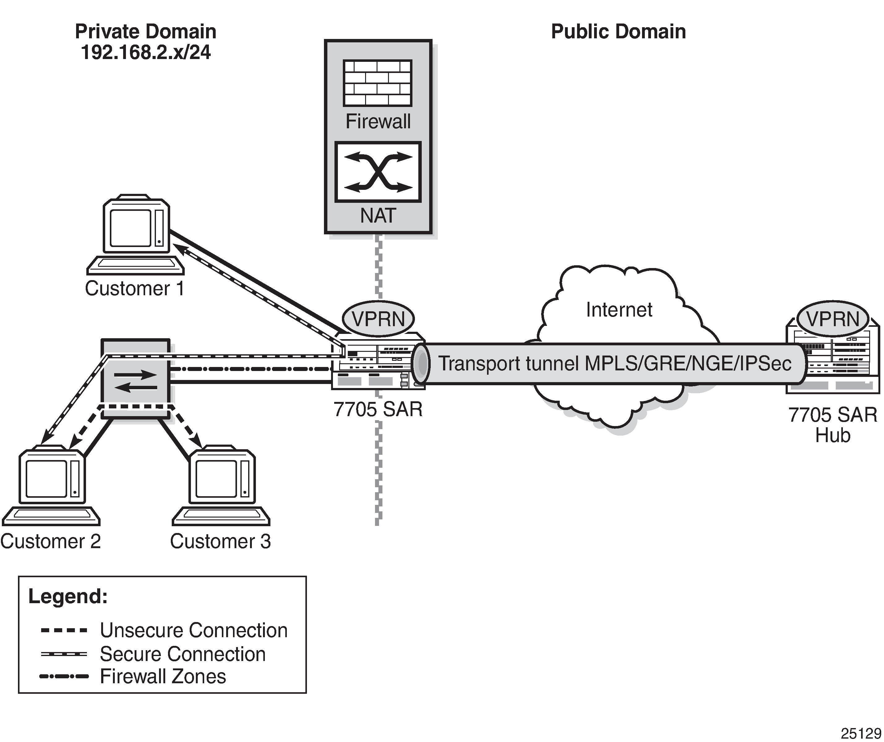
Firewall Protection for the Network Core shows a firewall on a VPRN, where the core of the network is protected from access devices and from any traffic entering the VPRN through the transport tunnel. A VPRN configured with access security policies can also protect access networks or LANs from each other.
A security zone can also be created with spoke SDPs or auto-bind tunnels that have been configured for a VPRN service using MP-BGP. For auto-bind tunnels, the auto-bind-tunnel resolution-filter type can be set to gre, ldp, rsvp, sr-isis, sr-ospf, or sr-te. When a zone contains spoke SDPs or auto-bind MPLS tunnels, it cannot contain any other type of interface. A zone configured with spoke SDPs or auto-bind MPLS tunnels will firewall traffic arriving from the access side to this zone for any MP-BGP transport tunnel residing in that Layer 3 service. After a security zone is created for MP-BGP transport tunnels, all MP-BGP transport tunnels going to far-end peers are part of this zone. Traffic entering or exiting the zone is firewalled; however, traffic traveling from one auto-bind tunnel to another within the same zone is not firewalled.
Static One-to-One NAT and VPRN
With static one-to-one NAT, NAT is performed on packets traveling from an inside (private) interface to an outside (public) interface or from an outside interface to an inside interface. Static one to-one NAT can be applied to a single IP address or a subnet of IP addresses and is performed on the IP header of a packet, not on the UDP/TCP port.
Mapping statements, or entries, can be configured to map an IP address range to a specific IP address. The direction of the NAT mapping entry dictates whether NAT is performed on a packet source IP address or subnet or on a packet destination IP address or subnet. The 7705 SAR supports inside mapping entries that map an inside IP address range to an outside IP address range sequentially.
With an inside mapping entry, the following points apply.
Packets that originate from an inside interface and are destined for an inside interface are forwarded without any NAT being applied.
If there is a matching one-to-one NAT mapping entry, packets that originate from an inside interface and are destined for an outside interface undergo static one-to-one NAT where NAT changes the source IP address of the packet IP header. The packet is forwarded whether or not a NAT mapping entry is found unless the drop-packets-without-nat-entry command is enabled. When a mapping entry is not found and the drop-packets-without-nat-entry command is enabled, the packet is not forwarded.
If there is a matching one-to-one NAT mapping entry, packets that originate from an outside interface and are destined for an inside interface undergo static one-to-one NAT where NAT changes the destination IP address of the packet IP header. The packet is forwarded whether or not a NAT mapping entry is found unless the drop-packets-without-nat-entry command is enabled. When a mapping entry is not found and the drop-packets-without-nat-entry command is enabled, the packet is not forwarded.
Packets that originate from an outside interface and are destined for an outside interface are forwarded without any NAT being applied.
Static one-to-one NAT is supported in the GRT and in VPRNs. For more information about static one-to-one NAT, see the 7705 SAR Router Configuration Guide, ‟Static One-to-One NAT”.
For VPRNs, one-to-one NAT can be configured between an inside interface and a outside MP-BGP MPLS transport tunnel interface. Policies should be used to not leak the inside interface/IP address via MP-BGP to the peer. Policies should be used to leak the NAT routes to the MP-BGP peer.
VPRN Interfaces Supported for Static One-to-One NAT lists the types of outside and inside interfaces that are supported in a VPRN for one-to-one NAT.
VPRN Interface Type |
Outside |
Inside |
|---|---|---|
SAP interface |
✓ |
✓ |
R-VPLS interface |
✓ |
✓ |
Layer 3 spoke SDP interface |
✓ |
✓ |
IPSec private interface |
✓ |
✓ |
Auto-bind GRE/MPLS (MP-BGP), where MPLS includes segment routing, LDP, and RSVP |
✓ |
Unicast and Multicast Address Translation
The 7705 SAR supports unicast-to-multicast address translation and multicast-to-multicast address translation.
For unicast-to-multicast translation, the 7705 SAR translates the destination IP address of the unicast flow to a multicast group. For multicast-to-multicast translation, the 7705 SAR acts as a host to upstream (S,G)s and performs address translation to the downstream (S,G).
Unicast and multicast address translation is supported on the following adapter cards and platforms:
on the 7705 SAR-8 Shelf V2 and the 7705 SAR-18:
2-port 10GigE (Ethernet) Adapter card
6-port Ethernet 10Gbps Adapter card
8-port Gigabit Ethernet Adapter card, version 3
10-port 1GigE/1-port 10GigE X-Adapter card, version 2 (supported on the 7705 SAR-18 only)
7705 SAR-Ax
7705 SAR-H
7705 SAR-Hc
7705 SAR-Wx
7705 SAR-X
Unicast and multicast address translation is supported in the GRT and in VPRNs. For VPRNs, IPv4 addressing on SAP-to-SAP connections is supported.
For more information about unicast-to-multicast address translation and multicast-to-multicast address translation, see the 7705 SAR Routing Protocols Guide, ‟Unicast and Multicast Address Translation”.
Route Distinguishers
The route distinguisher (RD) is an 8-byte value consisting of two major fields: the Type field and Value field. The Type field determines how the value field should be interpreted. The 7705 SAR implementation supports the three (3) Type-Value combinations, as defined in RFC 2547bis. Route Distinguisher Structure illustrates the RD structure.

The three Type-Value combinations supported are described in Route Distinguisher Type-Value Fields.
Type Field |
Value Field |
Notes |
|---|---|---|
Type 0 |
Administrator subfield (2 bytes) |
The Administrator field must contain an AS number (using private AS numbers is discouraged) |
Assigned number subfield (4 bytes) |
The Assigned field contains a number assigned by the service provider |
|
Type 1 |
Administrator subfield (4 bytes) |
The Administrator field must contain an IP address (using private IP address space is discouraged) |
Assigned number subfield (2 bytes) |
The Assigned field contains a number assigned by the service provider |
|
Type 2 |
Administrator subfield (4 bytes) |
The Administrator field must contain a 4-byte AS number (using private AS numbers is discouraged) |
Assigned number subfield (2 bytes) |
The Assigned field contains a number assigned by the service provider |
PE-to-CE Route Exchange
Routing information between the Provider Edge (PE) and Customer Edge (CE) can be exchanged by the following methods:
EBGP (for IPv4 and IPv6 address families)
OSPF
OSPFv3
RIP
static routes
Each protocol provides controls to limit the number of routes learned from each CE router.
Route Redistribution
Routing information learned from the PE-to-CE routing protocols and configured static routes is injected into the associated local virtual routing and forwarding table (VRF). In the case of the dynamic routing protocols, there may be protocol-specific route policies that modify or reject certain routes before they are injected into the local VRF.
Route redistribution from the local VRF to the PE-to-CE routing protocols is controlled via the route policies in each routing protocol instance, in the same manner that is used by the base router instance.
The advertisement or redistribution of routing information from the local VRF to or from the MP-BGP instance is specified per VRF and is controlled by VRF route target associations or by VRF route policies.
A route belonging to a VPRN must use the protocol owner, VPN-IPv4, to denote that it is a VPRN route. This can be used within the route policy match criteria.
CPE Connectivity Check
Static routes are used within many IES and VPRN services. Unlike dynamic routing protocols, there is no way to change the state of routes based on availability information for the associated CPE. CPE connectivity check adds flexibility so that unavailable destinations are removed from the service provider’s routing tables dynamically, and wasted bandwidth is minimized.
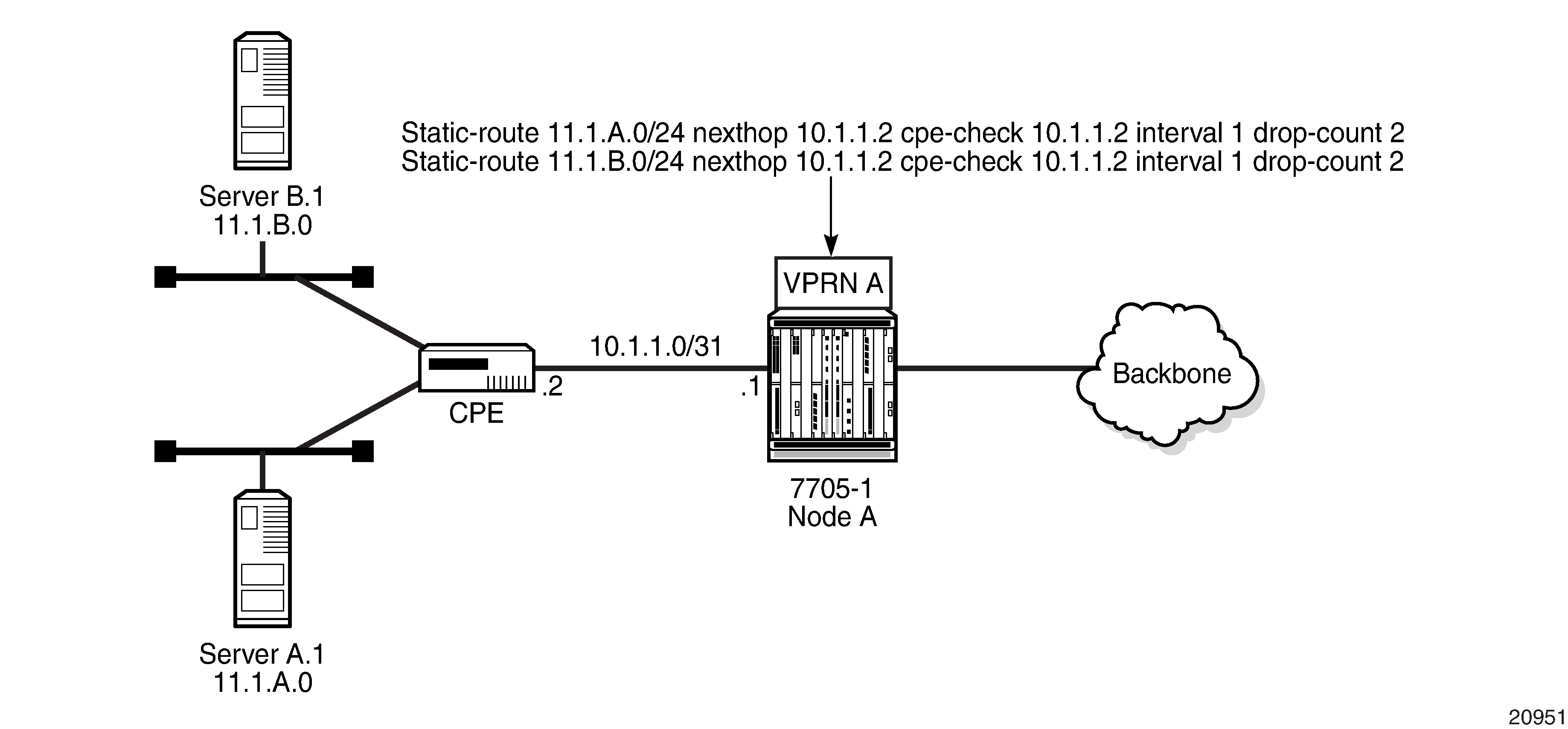
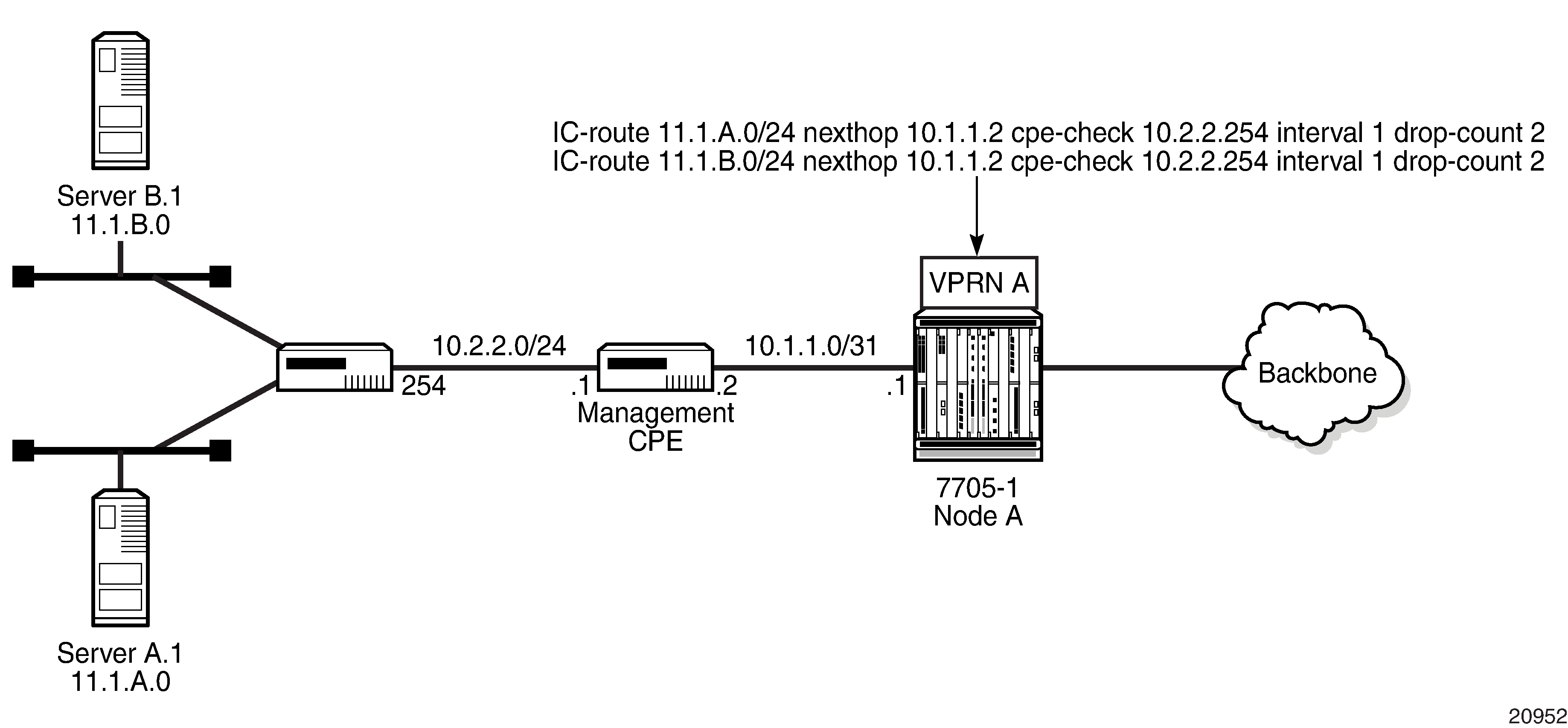
Directly Connected IP Target and Multiple Hops to IP Target illustrate the use of CPE connectivity check in directly connected and multiple-hop connected routes.
The availability of the far-end static route is monitored through periodic polling. The polling period is configured. If the poll fails a specified number of sequential polls, the static route is marked as inactive.
Either ICMP ping or unicast ARP mechanism can be used to test the connectivity. ICMP ping is preferred.
If the connectivity check fails and the static route is deactivated, the 7705 SAR router will continue to send polls and reactivate any routes that are restored.
Route Target Constraint
Route Target Constraint (RTC) is a mechanism that allows a router to advertise route target membership information to its BGP peers to indicate interest in receiving only VPN routes tagged with specific route target extended communities. Upon receiving RTC route information, peers restrict the advertised VPN routes to only those requested, minimizing control plane load in terms of protocol traffic and potentially reducing RIB memory usage.
The route target membership information is carried using MP-BGP, using an AFI value of 1 and SAFI value of 132. The NLRI of an RTC route encodes an Origin AS and a route target extended community using prefix type encoding with host bits after the prefix-length set to zero.
In order for two routers to exchange route target membership NLRI, they must advertise the corresponding AFI and SAFI to each other during capability negotiation. The use of MP-BGP means route target membership NLRI are propagated, loop-free, within an autonomous system and between autonomous systems, using well-known BGP route selection and advertisement rules.
Route target constrained route distribution and outbound route filtering (ORF) both allow routers to advertise which route target extended communities they want to receive in VPN routes from peers. RTC, however, is more widely supported, is simpler to configure, and its distribution scope is not limited to a direct peer.
Configuring the Route Target Address Family
RTC is supported only by the base router BGP instance. When the family command in the BGP router group or neighbor CLI context includes the route-target keyword, the RTC capability is negotiated with the associated set of EBGP and IBGP peers.
ORF and RTC are mutually exclusive for a particular BGP session. The CLI does not attempt to block the configuration of both ORF and RTC, but if both capabilities are enabled for a session, the ORF capability will not be included in the OPEN message sent to the peer.
Originating RTC Routes
When the base router has one or more RTC peers (BGP peers with which the RTC capability has been successfully negotiated), one RTC route is created for each route target extended community imported into a locally configured Layer 3 VPN service. These imported route targets are configured in the following contexts:
config>service>vprn
config>service>vprn>mvpn
By default, RTC routes are automatically advertised to all RTC peers without the need for an export policy to explicitly accept them. Each RTC route has a prefix, a prefix length, and path attributes. The prefix value is the concatenation of the origin AS (a 4-byte value representing the 2-octet or 4-octet AS of the originating router, as configured using the config>router>autonomous-system command) and 0 or 16 to 64 bits of a route target extended community encoded in one of the following formats: 2-octet AS specific extended community, IPv4 address specific extended community, or 4-octet AS specific extended community.
A router may be configured to send the default RTC route to a group or neighbor with the default-route-target CLI command. The default RTC route is a special route that has a prefix length of zero. Sending the default RTC route to a peer conveys a request to receive all VPN routes from that peer, whether they match the route target extended community. The default RTC route is typically advertised by a route reflector to PE clients. Advertising the default RTC route to a peer does not suppress other more specific RTC routes from being sent to that peer. A received default RTC route is never propagated to other routers.
Receiving and Readvertising RTC Routes
All received RTC routes that are considered valid are stored in the RIB-In. RTC routes are considered invalid and treated as withdrawn if the prefix length is configured to be any of the following:
1 to 31
33 to 47
48 to 96 and the 16 most-significant bits are not 0x0002, 0x0102, or 0x0202
If multiple RTC routes are received for the same prefix value (same NLRI), then standard BGP best-path selection procedures are used to determine the best route. The propagation of the best path installs RIB-Out filter rules as it travels from one router to the next, and this process creates an optimal VPN route distribution tree rooted at the source of the RTC route.
The best RTC route per prefix is readvertised to RTC peers based on the following rules.
The best path for a default RTC route (prefix length 0, origin AS only with prefix length 32, or origin AS plus 16 bits of a route target type with prefix-length 48) is never propagated to another peer.
A PE with only IBGP RTC peers that is not a route reflector or an ASBR does not readvertise the best RTC route to any RTC peer, due to standard IBGP split-horizon rules.
A route reflector that receives its best RTC route for a prefix from a client peer readvertises that route (subject to export policies) to all its client and non-client IBGP peers (including the originator), per standard route reflector operation. When the route is readvertised to client peers, the route reflector sets the ORIGINATOR_ID to its own router ID and modifies the NEXT_HOP to be its local address for the sessions (for example, system IP).
A route reflector that receives its best RTC route for a prefix from a non-client peer readvertises that route (subject to export policies) to all its client peers, per standard route reflector operation. If the route reflector has a non-best path for the prefix from any of its clients, it advertises the best of the client-advertised paths to all non-client peers.
An ASBR that is not a PE or a route reflector, that receives its best RTC route for a prefix from an IBGP peer, readvertises that route (subject to export policies) to its EBGP peers. The NEXT_HOP and AS_PATH of the re-advertised route are modified per standard BGP rules. No aggregation of RTC routes is supported.
An ASBR that is not a PE or a route reflector, that receives its best RTC route for a prefix from an EBGP peer, readvertises that route (subject to export policies) to its EBGP and IBGP peers. The NEXT_HOP and AS_PATH of the re-advertised route are modified per standard BGP rules. No aggregation of RTC routes is supported.
Using RTC Routes
In general, the best VPN route for every prefix or NLRI in the RIB is sent to every peer supporting the VPN address family. Export policies may be used to prevent some prefixes or NLRIs from being advertised to specific peers. These export policies may be configured statically, or created dynamically by using ORF or RTC with a peer. ORF and RTC are mutually exclusive for a session.
When RTC is configured on a session that also supports VPN address families using route targets (VPN-IPv4, VPN-IPv6, or MVPN-IPv4), the advertisement of the VPN routes is affected as follows.
When the session comes up, the advertisement of the VPN routes is delayed for a short while to allow RTC routes to be received from the peer.
After the initial delay, the received RTC routes are analyzed and acted upon. If S1 is the set of routes previously advertised to the peer and S2 is the set of routes that should be advertised based on the most recent received RTC routes, then:
the set of routes in S1 but not in S2 are withdrawn immediately (subject to the minimum route advertisement interval (MRAI)
the set of routes in S2 but not in S1 are advertised immediately (subject to the MRAI)
If a default RTC route is received from a peer P1, the set of VPN routes that are advertised to P1 are routes that:
are eligible for advertisement to P1 per BGP route advertisement rules
have not been rejected by manually configured export policies
have not been advertised to the peer
This applies whether or not P1 advertised the best route for the default RTC prefix. A default RTC route is a route with any of the following:
NLRI length = zero
NLRI value = origin AS and NLRI length = 32
NLRI value = {origin AS+0x0002 | origin AS+0x0102 | origin AS+0x0202} and NLRI length = 48
If an RTC route for prefix A (origin-AS = A1, RT = A2/n, n > 48) is received from an IBGP peer I1 in autonomous system A1, the set of VPN routes that are advertised to I1 are the routes that:
are eligible for advertisement to I1 per BGP route advertisement rules
have not been rejected by manually configured export policies
carry at least one route target extended community with value A2 in the n most significant bits
have not been advertised to the peer
This applies whether or not I1 advertised the best route for A.
If the best RTC route for a prefix A (origin-AS = A1, RT = A2/n, n > 48) is received from an IBGP peer I1 in autonomous system B, the set of VPN routes that are advertised to I1 are routes that:
are eligible for advertisement to I1 per BGP route advertisement rules
have not been rejected by manually configured export policies
carry at least one route target extended community with value A2 in the n most significant bits
have not been advertised to the peer
This applies only if I1 advertised the best route for A.
If the best RTC route for a prefix A (origin-AS = A1, RT = A2/n, n > 48) is received from an EBGP peer E1, the set of VPN routes that are advertised to E1 are the routes that:
are eligible for advertisement to E1 per BGP route advertisement rules
have not been rejected by manually configured export policies
carry at least one route target extended community with value A2 in the n most significant bits
have not been advertised to the peer
This applies only if E1 advertised the best route for A.
In-Band Management using a VPRN
VPRN in-band management is supported on the 7705 SAR. In-band management of the 7705 SAR is performed using the global routing table (GRT) to perform a lookup on the system IP address of the 7705 SAR.
On network ingress, when a packet arrives from the transport tunnel to the VPRN, a lookup is performed within the VPRN on the inner customer packet IP header. If a destination IP address in the packet header matches any system IP address configured under grt-lookup with a GRT static-route-entry set to the system IP address specified under vprn>static-route-entry>grt, the packet is extracted to the CSM for processing. If the vprn>grt-lookup>enable-grt>allow-local-management command is not enabled, the packet is routed using the 7705 SAR VRF FIB.
If the 7705 SAR system IP address is the same as any local IP address within the VPRN and the arriving packet destination IP matches this address, the packet is extracted to the CSM for processing only if the allow-local-management command is enabled. Any ICMP packet destined for local interfaces will be processed by the system IP. If the local interface is operationally down, the system IP will still reply to ICMP packets successfully. Having a single IP address shared by the system IP and VPRN local interface is not recommended because some GRT-supported management protocols, such as Telnet and SSH, will not function with this configuration.
For MP-BGP VPRNs, the system IP address can be advertised to the far-end node using a static route configured under vprn>static-route-entry>grt. If the command allow-local-management is enabled under the VPRN instance, a packet arriving on a transport tunnel will be extracted to the CSM before hitting the blackhole route. In this case, the only effect of the blackhole route will be to advertise the system IP address to the far-end peer. If the command allow-local-management is not enabled, packet forwarding will be the default forwarding mode; that is, all packets destined for the system IP address will be blackholed because of the static route configuration.
For MP-BGP VPRNs, when the command allow-local-management is enabled, at least one interface (such as a loopback interface) must be configured on the VPRN and have an operational status of Up.
On network egress, the packets generated from the CSM with a source IP address that matches the local IP address and destination IP address of either the far-end NSP NFM-P or other management entity must perform a GRT route lookup in order to be resolved. A route policy can be configured with an IP address prefix of the far-end management entity and with the action to accept. This policy is configured for the GRT under the config>router>policy-options context and is installed in the GRT FIB using the export-grt command. The route installed in the GRT FIB will have a next hop of the corresponding VRF tunnel. This prevents any user data traffic in the GRT data path from leaking into the VPRN, and ensures that only the management traffic originating from the system IP address and the CSM gets transported through the VPRN. This forces the management packet to get routed by the corresponding VPRN transport tunnel, which means the VPRN route is leaked into the GRT so the GRT resolves the route using the corresponding VPRN.
IPv4 and IPv6 GRT-Supported Management Protocols lists the management protocols supported by IPv4 and IPv6 GRT in the reverse and forward directions.
Protocol |
Reverse Direction (Towards the 7705 SAR) |
Forward Direction (From the 7705 SAR) |
|---|---|---|
FTP Passive and Active |
✓1 |
✓2 |
SFTP |
✓1 |
|
NTP |
✓3 |
|
RADIUS |
✓ |
|
SCP |
✓1 |
✓3 |
SNMP |
✓ |
|
SNMP Trap |
✓ |
|
SSH |
✓1 |
✓3 |
TACACS+ |
✓ |
|
Telnet |
✓1 |
✓3 |
TWAMP 4 |
✓5 |
✓6 |
TWAMP Light |
✓5 |
✓6 |
Notes:
Supported, if the 7705 SAR is acting as a server
Supported, if the 7705 SAR is acting as an active client
Supported, if the 7705 SAR is acting as a client
Supported on IPv4 only
Supported, if the 7705 SAR is acting as a server (control packets)
Supported, if the 7705 SAR is acting as a session reflector (test packets)
IPv4 In-Band Management Using a VPRN Configured with GRT Lookup shows an example of IPv4 in-band management of the 7705 SAR and the switches behind it by the NSP NFM-P and a TACACS+ server. In the example, an IPSec tunnel is being used as the VPRN in order to transport the management traffic via a secure and encrypted medium over the public internet.
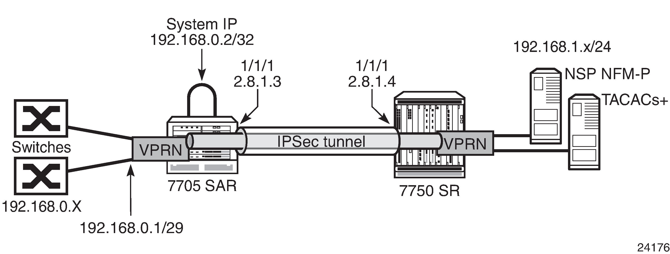
In this example, the 7705 SAR system IP address is in the same subnet as the local interface; that is, subnet 192.168.0.x.
On network ingress in the above example, when allow-local-management is configured for the VPRN, packets arriving on the 192.168.0 subnet are treated as follows.
If the packet destination IP address is 192.168.0.2, the packet is extracted to the CSM to be processed as management traffic.
If the packet is destined for subnet 192.168.0.x/29, it is forwarded out of interface 192.168.0.1.
On network egress in the above example, routing is as follows.
A static route can be installed in the 7705 SAR VPRN for subnet 192.168.1.0/24 with a next hop to IPSecTunnel_1.
A route policy can be created with an IP address prefix of 192.168.1.0/24 and an action to accept. This route policy is configured under the config>router>policy-options context, and can be exported to the GRT FIB using the export-grt command.
The above configuration will add route 192.168.1.0/24 to the GRT FIB with the next hop being the corresponding VPRN IPSec tunnel. This entry will force the CSM-generated packets destined for the 192.168.1.x subnet to be resolved by the VPRN IPSec tunnel.
IPv6 In-Band Management Using a VPRN Configured with GRT Lookup shows an example of IPv6 in-band management of the 7705 SAR and the switches behind it by the NSP NFM-P and a TACACS+ server.
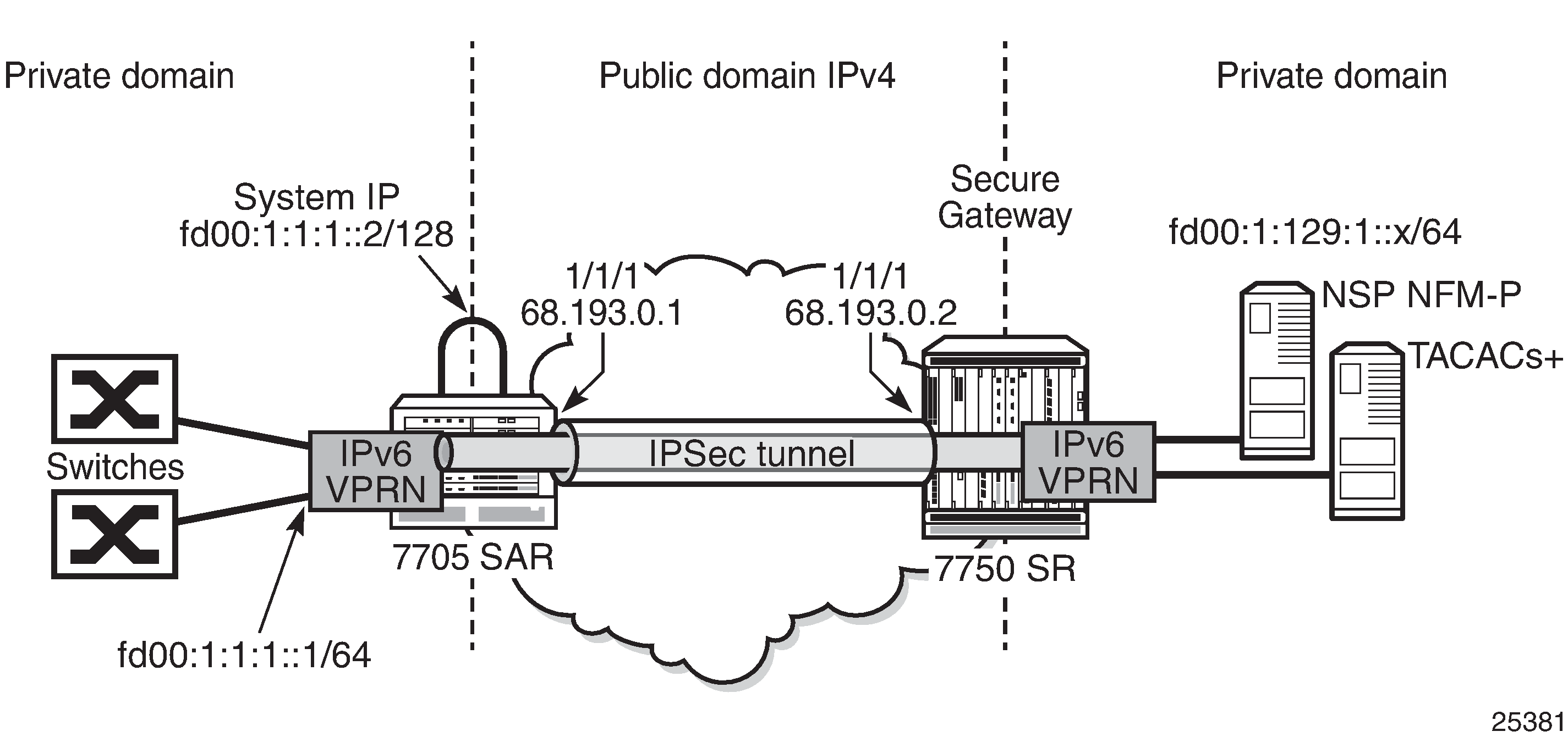
On network ingress in the above example, the 7705 SAR system IP address is in the same subnet as the local interface IPv6 VPRN address. When allow-local-management is configured for the IPv6 VPRN, packets arriving on the fd00:1:1:1 subnet are treated as follows.
If the packet destination IP address is fd00:1:1:1::2, the packet is extracted to the CSM to be processed as management traffic.
If the packet is destined for subnet fd00:1:1:1::/64, it is forwarded out of interface fd00:1:1:1::1.
On network egress in the above example, routing is as follows.
A static route can be installed at the 7705 SAR VPRN for subnet fd00:1:129:1::/64 with a next hop to IPSecTunnel_1.
A route policy can be created with an IP address prefix of fd00:1:129:1::/64 and an action to accept. This route policy is configured under the config>router>policy-options context, and can be exported to the GRT FIB using the export-grt command.
The above configuration adds route fd00:1:129:1::/64 to the GRT FIB with the next hop being the corresponding VPRN IPSec tunnel. This entry forces the CSM-generated packets destined for the fd00:1:129:1::x subnet to be resolved by the VPRN IPSec tunnel.