NG-MVPN Configuration with PIM
This chapter provides information about multicast in a VPRN service.
Topics in this chapter include:
Applicability
Initially, this chapter was written for SR OS Release 7.0.R5. The configuration in the current edition is based on SR OS Release 23.7.R2. There are no prerequisites for this configuration.
Overview
Multicast VPN (MVPN) architectures describe a set of VRFs that support the transport of multicast traffic across a provider network.
RFC 6037 (herein referred to as Rosen MVPN) describes the use of Multicast Distribution Trees (MDTs) established between PEs within a VRF. Each VRF requires its own tree. Customer Edge (CE) routers form Protocol Independent Multicast (PIM) adjacencies with the PE, and PE-PE PIM adjacencies are formed across the multicast tree. PIM signaling and data streams are transported across the MDT. There are a number of limitations with the Rosen MVPN implementation including, but not limited to:
-
Rosen MVPN requires a set of MDTs per VPN, which requires a PIM state per MDT. There is no option to aggregate MDT across multiple VPNs
-
Customer signaling, PE discovery and Data MDT signaling are all PIM-based. There is no mechanism available to decouple these. Thus there is an incongruency between unicast and multicast VPNs using Rosen MVPN.
-
There is no mechanism for using MPLS to encapsulate multicast traffic in the VPN. GRE is the only encapsulation method available in Rosen MVPN.
-
Rosen MVPN multicast trees are signaled using PIM only. Next Generation MVPN (NG MVPN) allows the use of mLDP, RSVP P2MP LSPs.
-
PE to PE protocol exchanges for Rosen MVPN is achieved using PIM only. NG MVPN allows for the use of BGP signaling as per unicast Layer 3 VPNs.
-
NG MVPN addresses these limitations by extending the idea of the per-VRF tree, by introducing the idea of Provider Multicast Service Interfaces (PMSI). These are equivalent to the default MDTs of Rosen MVPN in that they support control plane traffic (customer multicast signaling), and the data MDTs which carry multicast data traffic streams between PEs within a multicast VRF.
NG MVPN allows the decoupling of the mechanism required to create a multicast VPN, such as PE auto-discovery (which PEs are members of which VPN), PMSI signaling (creation of tunnels between PEs) and customer multicast signaling (multicast signaling -IGMP/PIM- received from CE routers). Two types of PMSI exist:
-
Inclusive (I-PMSI): contains all the PEs for an MVPN.
-
Selective (S-PMSI): contains only a subset of PEs of an MVPN.
Knowledge of MPLS-VPN RFC 4364, BGP/MPLS IP Virtual Private Networks (VPNs), architecture and functionality, as well as an understanding of multicast protocols, is assumed throughout.
This chapter provides configuration details required to implement the parts of NG MVPN shown in NG MVPN Components.
|
Provider Multicast Domain |
Customer Multicast Domain |
|||||
|---|---|---|---|---|---|---|
|
I-PMSI |
Auto-discovery |
C-Mcast |
S-PMSI Creation |
PE-based RP |
Anycast RP on PE |
PIM SSM |
|
PIM ASM |
PIM |
PIM join/leave |
PIM SSM with S-PMSI join TLV |
X |
X |
X |
|
PIM ASM |
BGP A/D |
PIM join/leave |
PIM SSM with S-PMSI join TLV |
X |
||
The first section of this chapter describes the common configuration required for each PE within the provider multicast domain, regardless of the MVPN PE auto-discovery or customer signaling methods. This includes IGP and VPRN service configuration.
Following the common configuration, specific MVPN configuration required for the configuration for the provider multicast domain using PIM Any Source Multicast (ASM) with auto-discovery based on PIM or BGP auto-discovery (A/D), PIM used for the customer multicast signaling and PIM Source Specific Multicast (SSM) used for the S-PMSI creation are described. The customer domain configuration covers the following three cases:
-
PIM ASM with the Rendezvous Point (RP) in the provider PE
-
PIM ASM using anycast RP on the provider RPs
-
PIM SSM
Other possible options, not covered in this section, are described in the 7450 ESS, 7750 SR, 7950 XRS, and VSR Multicast Routing Protocols Guide:
-
The use of PIM SSM for the provider multicast I-PMSI.
-
The use of BGP for the customer multicast signaling in the provider multicast domain.
-
The provider S-PMSI creation through BGP S-PMSI A/D.
-
The use of the customer RP based in the customer CE.
The use of mLDP and RSVP p2mp LSPs for the I/S-PMSI was not available in Release 7.0.
The Multicast in a VPRN II example in NG-MVPN Configuration with MPLS introduces features that were not supported in Release 7.0.R5. It provides configuration details to implement:
-
Multicast LDP (mLDP) and RSVP-TE Point to Multi-point (P2MP) for building customer trees (C-trees) which are using MPLS instead of PIM techniques.
-
MVPN source redundancy
-
MDT AFI/SAFI (to fully interoperate with Cisco networks).
References
-
IETF
-
RFC 6513, Multicast in MPLS/BGP IP VPNs
-
RFC 6514, BGP Encodings and Procedures for Multicast in MPLS/ BGP IP VPNs
-
-
7450 ESS, 7750 SR, 7950 XRS, and VSR Layer 3 Services Guide: IES and VPRN
Topology
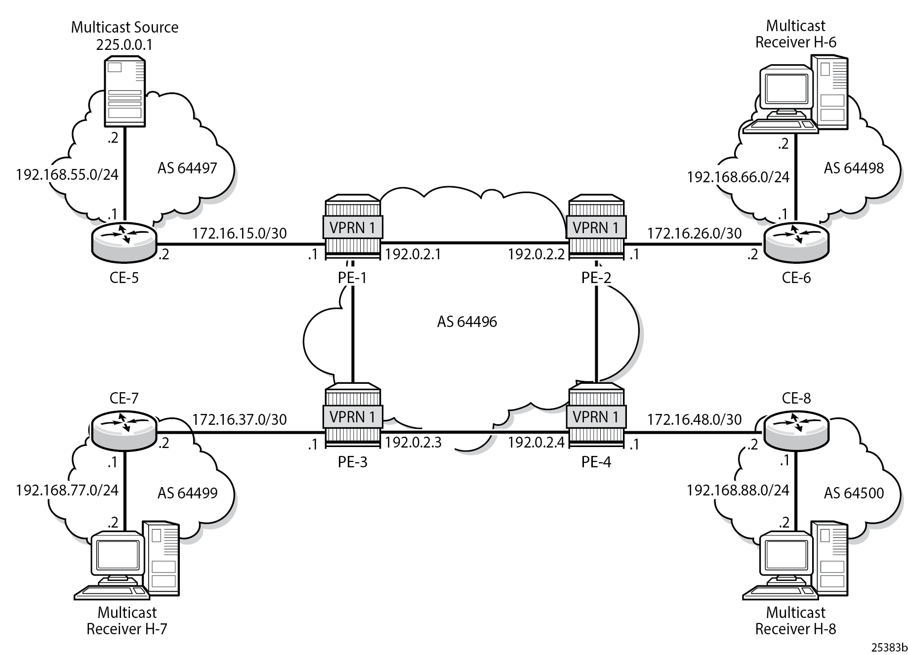
The network topology is displayed in Network Topology. The setup consists of four SR 7750s acting as Provider Edge (PE) routers within a single Autonomous System (AS).
-
Full mesh IS-IS or OSPF in each AS
-
LDP on all interfaces in each AS (RSVP could also be used)
-
MP-iBGP sessions between the PE routers in each AS (Route Reflectors (RRs) could also be used).
-
Layer 3-VPN on all PEs with identical route targets, in the form AS-number: vprn-service-id
Connected to each PE is a single SR OS router acting as a Customer Edge (CE) router. CE-5 has a multicast source connected, and CE-6, CE-7, and CE-8 each have a single receiver connected which receive the multicast streams from the source. In this document, each receiver is both IGMPv2 and IGMPv3 capable. If the customer domain multicast signaling plane uses Source Specific Multicasting (SSM), then an IGMPv3 receiver is configured; if Any Source Multicasting (ASM) is used, the receiver is IGMPv2 capable.
If the receiver is IGMPv3 capable, it issues IGMPv3 reports that include a list of required source addresses. The receiver joins the 232.0.0.1 multicast group.
If the receiver is only IGMPv2 capable, then it issues IGMPv2 reports which do not specify a source of the group. In this case, a Rendezvous Point is required within the PIM control plane of the multicast VRF which is source-aware. In this case, the receiver joins the 225.0.0.1 multicast group.
When the receiver wants to become a member of any group, the source address of the group must be known to the CE. As a result, the source address must be IP reachable by each CE, so it is advertised by CE-5 to the PEs with attachment circuits in VPRN1 using BGP.
Static routes are then configured on the receiver CEs to achieve IP reachability to the source address of multicast groups. In the case of PIM ASM, any RP that is configured must also be reachable from the CE.
Multicast VPN Overview
Multicast traffic from the source is streamed toward router CE-5. Receivers connected to CE-6, CE-7 and CE-8 are interested in joining this multicast group.
All CEs are PIM enabled routers, which form a PIM adjacency with their nearest PE. The PIM adjacencies between PEs across the Provider network are achieved using I-PMSIs. I-PMSIs carry PIM control messages between PEs. Data plane traffic is transported across the I-PMSI until a configured bandwidth threshold is reached. A Selective PMSI is then signaled that carries data plane traffic. This threshold can be as low as 1kb/second and must be explicitly configured along with the S-PMSI multicast group. An S-PMSI per customer group per VPRN is configured. If no S-PMSI and threshold is configured, data traffic continues to be forwarded across the provider network within the I-PMSI.
Configuration
The configuration is divided into the following sections:
Provider Common Configuration
This section describes the common configuration required for each PE within the Provider multicast domain, regardless of the MVPN PE auto-discovery or customer signaling methods. This includes IGP and VPRN service configuration.
The configuration tasks can be summarized as follows:
-
PE Global Configuration. This includes configuration of the Interior Gateway Protocol (IGP) (IS-IS or OSPF); configuration of link layer LDP between PEs; configuration of iBGP between PEs, to facilitate VPRN route learning; configuration of PIM.
-
PE VPRN Configuration. This includes configuration of basic VPRN parameters (route-distinguisher, route target communities); configuration of attachment circuits toward CEs; configuration of VRF routing protocol and any policies toward CE.
-
VRF PIM and MVPN parameters - I-PMSI
-
CE configuration.
PE Global Configuration
-
On each of the PE routers, configure the appropriate router interfaces, OSPF (or IS-IS) and link layer LDP. For clarity in the following configuration steps, only the configuration for PE-1 is shown. PE-2, PE-3, and PE-4 are similar.
On PE-1: configure router interface "int-PE-1-PE-2" address 192.168.12.1/30 port 1/1/c1/1 exit interface "int-PE-1-PE-3" address 192.168.13.1/30 port 1/1/c2/1 exit interface "system" address 192.0.2.1/32 exit autonomous-system 64496 ospf 0 area 0.0.0.0 interface "system" exit interface "int-PE-1-PE-2" interface-type point-to-point exit interface "int-PE-1-PE-3" interface-type point-to-point exit exit no shutdown exit ldp interface-parameters interface "int-PE-1-PE-2" exit interface "int-PE-1-PE-3" exit exit exit exit all -
Verify that OSPF adjacencies are formed and that LDP peer sessions are formed.
*A:PE-1# show router ospf neighbor

===============================================================================
Rtr Base OSPFv2 Instance 0 Neighbors
===============================================================================
Interface-Name                   Rtr Id          State      Pri  RetxQ   TTL
   Area-Id
-------------------------------------------------------------------------------
int-PE-1-PE-2                    192.0.2.2       Full       1    0       31
   0.0.0.0
int-PE-1-PE-3                    192.0.2.3       Full       1    0       33
   0.0.0.0
-------------------------------------------------------------------------------
No. of Neighbors: 2
===============================================================================
*A:PE-1# show router ldp session ipv4 ============================================================================== LDP IPv4 Sessions ============================================================================== Peer LDP Id Adj Type State Msg Sent Msg Recv Up Time ------------------------------------------------------------------------------ 192.0.2.2:0 Link Established 43 44 0d 00:01:29 192.0.2.3:0 Link Established 27 29 0d 00:00:47 ------------------------------------------------------------------------------ No. of IPv4 Sessions: 2 ============================================================================== -
Configure BGP between the PEs for VPRN routing.
On PE-1: configure router bgp group "INTERNAL" family vpn-ipv4 type internal neighbor 192.0.2.2 exit neighbor 192.0.2.3 exit neighbor 192.0.2.4 exit exit no shutdown exit all -
Verify that BGP sessions are established for address family VPN-IPv4.
*A:PE-1# show router bgp summary all =============================================================================== BGP Summary =============================================================================== Legend : D - Dynamic Neighbor =============================================================================== Neighbor Description ServiceId AS PktRcvd InQ Up/Down State|Rcv/Act/Sent (Addr Family) PktSent OutQ ------------------------------------------------------------------------------- 192.0.2.2 Def. Inst 64496 5 0 00h00m33s 0/0/0 (VpnIPv4) 5 0 192.0.2.3 Def. Inst 64496 3 0 00h00m23s 0/0/0 (VpnIPv4) 3 0 192.0.2.4 Def. Inst 64496 3 0 00h00m12s 0/0/0 (VpnIPv4) 3 0 ------------------------------------------------------------------------------- -
Enable PIM on all network interfaces, including the system interface. This allows the signaling of PMSIs that transport PIM signaling within each VRF.
-
Each I-PMSI is signaled using PIM ASM, so a rendezvous point (RP) is required within the global PIM configuration. A static RP is used and PE-1 is selected. All PEs must be configured with this RP address.
On PE-1: configure router pim interface "system" exit interface "int-PE-1-PE-2" exit interface "int-PE-1-PE-3" exit rp static address 192.0.2.1 group-prefix 239.255.0.0/16 exit exit exit exit all -
The following command shows the PIM neighbor relationships.
*A:PE-1# show router pim neighbor

===============================================================================
PIM Neighbor ipv4
===============================================================================
Interface               Nbr DR Prty     Up Time       Expiry Time     Hold Time
   Nbr Address
-------------------------------------------------------------------------------
int-PE-1-PE-2           1               0d 00:00:41   0d 00:01:36     105
   192.168.12.2
int-PE-1-PE-3           1               0d 00:00:29   0d 00:01:17     105
   192.168.13.2
-------------------------------------------------------------------------------
Neighbors : 2
===============================================================================
PE VPRN Configuration
A VPRN (VPRN 1) is created on each PE. This is the multicast VPRN. PE-1 is the PE containing the attachment circuit toward CE-5. CE-5 is the CE nearest the source. PE-2, PE-3, and PE-4 contain attachment circuits toward CE-6, CE-7, and CE-8 respectively. CE-6 has receiving host H-6 attached; CE-7 has receiving host H-7, and CE-8 receiving host H-8.
-
Create VPRN 1 on each PE, containing a route-distinguisher and vrf-target of 64496:1. The autonomous system number is 64496. Use auto-bind-tunnel resolution-filter ldp for next hop tunnel route resolution.
On PE-1: configure service vprn 1 name "VPRN 1" customer 1 create autonomous-system 64496 bgp-ipvpn mpls auto-bind-tunnel resolution-filter ldp exit resolution filter exit route-distinguisher 64496:1 vrf-target target:64496:1 no shutdown exit exit no shutdown exit all -
Create an attachment circuit interface on PE-1 toward CE-5.
On PE-1: configure service vprn 1 interface "int-PE-1-CE-5" create address 172.16.15.1/30 sap 1/1/c3/1 create exit exit no shutdown exit all -
The source address of the multicast stream must be reachable by all routers (PEs and CEs) within the VPN. This is advertised within BGP from the CE to the PE. Create a BGP peering relationship within VPRN 1 on PE-1 with CE-5.
On PE-1: configure service vprn 1 bgp group "EXTERNAL" type external peer-as 64497 neighbor 172.16.15.2 exit exit exit no shutdown exit all -
On CE-5, create a VPRN to support the connection of the source to the CE and to connect the CE to the PE. Two attachment circuits are required, as well as a BGP peering relationship with the PE. This uses a default address family of ipv4.
(A pair of IES services could also be used to provide the attachment circuits.)
On CE-5: configure service vprn 1 name "VPRN 1" customer 1 create autonomous-system 64497 bgp-ipvpn mpls route-distinguisher 64497:1 no shutdown exit exit interface "int-CE-5-PE-1" create address 172.16.15.2/30 sap 1/1/c1/1 create exit exit interface "int-CE-5-S-5" create address 192.168.55.1/24 sap 1/1/c3/1 create exit exit bgp group "EXTERNAL" type external peer-as 64496 neighbor 172.16.15.1 exit exit exit no shutdown exit all -
The following BGP summaries show that the PE-CE BGP peer relationship between CE-5 and PE-1 is established for address family IPv4:
*A:CE-5# show router 1 bgp summary all

===============================================================================
BGP Summary
===============================================================================
Legend : D - Dynamic Neighbor
===============================================================================
Neighbor
Description
ServiceId          AS PktRcvd InQ  Up/Down   State|Rcv/Act/Sent (Addr Family)
                      PktSent OutQ
-------------------------------------------------------------------------------
172.16.15.1
1               64496       5    0 00h00m53s 0/0/0 (IPv4)
                            5    0
-------------------------------------------------------------------------------
*A:PE-1# show router 1 bgp summary =============================================================================== BGP Router ID:192.0.2.1 AS:64496 Local AS:64496 =============================================================================== BGP Admin State : Up BGP Oper State : Up Total Peer Groups : 1 Total Peers : 1 Current Internal Groups : 1 Max Internal Groups : 1 Total BGP Paths : 9 Total Path Memory : 3168 Total IPv4 Remote Rts : 0 Total IPv4 Rem. Active Rts : 0 ---snip--- =============================================================================== BGP Summary =============================================================================== Legend : D - Dynamic Neighbor =============================================================================== Neighbor Description AS PktRcvd InQ Up/Down State|Rcv/Act/Sent (Addr Family) PktSent OutQ ------------------------------------------------------------------------------- 172.16.15.2 64497 5 0 00h00m50s 0/0/0 (IPv4) 5 0 ------------------------------------------------------------------------------- -
For the CE connecting to the source to be advertised within BGP, a route policy is required. The subnet containing the multicast source is 192.168.55.0/24, so a prefix-list can be used to define a match, and then used within a route policy to inject into BGP.
On CE-5: configure router policy-options begin prefix-list "SOURCE-PREFIX" prefix 192.168.55.0/24 exact exit policy-statement "EXPORT-SOURCE-PREFIX-TO-BGP" entry 10 from prefix-list "SOURCE-PREFIX" exit to protocol bgp exit action accept exit exit exit commit exit all -
Apply this policy as an export policy within the bgp context.
On CE-5:
configure
    service
        vprn 1
            bgp
                export "EXPORT-SOURCE-PREFIX-TO-BGP"
            exit
            no shutdown
        exit all
This results in the 192.168.55.0/24 subnet being seen in the BGP RIB OUT Entries on CE-5.
*A:CE-5# show router 1 bgp routes 192.168.55.0/24 hunt
===============================================================================
 BGP Router ID:192.0.2.5        AS:64497       Local AS:64497
===============================================================================
 Legend -
 Status codes  : u - used, s - suppressed, h - history, d - decayed, * - valid
                 l - leaked, x - stale, > - best, b - backup, p - purge
 Origin codes  : i - IGP, e - EGP, ? - incomplete

===============================================================================
BGP IPv4 Routes
===============================================================================
-------------------------------------------------------------------------------
RIB In Entries
-------------------------------------------------------------------------------
---snip---
-------------------------------------------------------------------------------
RIB Out Entries
-------------------------------------------------------------------------------
Network        : 192.168.55.0/24
Nexthop        : 172.16.15.2
Path Id        : None
To             : 172.16.15.1
Res. Protocol  : INVALID                Res. Metric    : 0
Res. Nexthop   : n/a
Local Pref.    : n/a                    Interface Name : NotAvailable
Aggregator AS  : None                   Aggregator     : None
Atomic Aggr.   : Not Atomic             MED            : None
AIGP Metric    : None                   IGP Cost       : n/a
Connector      : None
Community      : No Community Members
Cluster        : No Cluster Members
Originator Id  : None                   Peer Router Id : 192.0.2.1
Origin         : IGP
AS-Path        : 64497
Route Tag      : 0
Neighbor-AS    : 64497
DB Orig Val    : N/A                    Final Orig Val : N/A
Source Class   : 0                      Dest Class     : 0

-------------------------------------------------------------------------------
Routes : 2
===============================================================================
It is also seen in the PE-1 VRF 1 FIB:
*A:PE-1# show router 1 route-table

===============================================================================
Route Table (Service: 1)
===============================================================================
Dest Prefix[Flags]                            Type    Proto     Age        Pref
      Next Hop[Interface Name]                                    Metric
-------------------------------------------------------------------------------
172.16.15.0/30                                Local   Local     00h04m48s  0
       int-PE-1-CE-5                                                0
172.16.26.0/30                                Remote  BGP VPN   00h04m11s  170
       192.0.2.2 (tunneled)                                         1
172.16.37.0/30                                Remote  BGP VPN   00h04m18s  170
       192.0.2.3 (tunneled)                                         1
172.16.48.0/30                                Remote  BGP VPN   00h04m16s  170
       192.0.2.4 (tunneled)                                         2
192.168.55.0/24                               Remote  BGP       00h01m08s  170
       172.16.15.2                                                  0
-------------------------------------------------------------------------------
No. of Routes: 5
Flags: n = Number of times nexthop is repeated
       B = BGP backup route available
       L = LFA nexthop available
       S = Sticky ECMP requested
===============================================================================
This prefix is also automatically advertised within the BGP VPRN to all other PEs, and is installed in VRF 1.
For example, on PE-2:
*A:PE-2# show router 1 route-table

===============================================================================
Route Table (Service: 1)
===============================================================================
Dest Prefix[Flags]                            Type    Proto     Age        Pref
      Next Hop[Interface Name]                                    Metric
-------------------------------------------------------------------------------
172.16.15.0/30                                Remote  BGP VPN   00h04m37s  170
       192.0.2.1 (tunneled)                                         1
172.16.26.0/30                                Local   Local     00h04m41s  0
       int-PE-2-CE-6                                                0
172.16.37.0/30                                Remote  BGP VPN   00h04m05s  170
       192.0.2.3 (tunneled)                                         2
172.16.48.0/30                                Remote  BGP VPN   00h04m12s  170
       192.0.2.4 (tunneled)                                         1
192.168.55.0/24                               Remote  BGP VPN   00h01m03s  170
       192.0.2.1 (tunneled)                                         1
-------------------------------------------------------------------------------
No. of Routes: 5
Flags: n = Number of times nexthop is repeated
       B = BGP backup route available
       L = LFA nexthop available
       S = Sticky ECMP requested
===============================================================================
Each CE containing the multicast receivers must be able to reach the source. The following shows the VPRN configuration of CE-6 containing an interface toward PE-2 and an interface toward receiving host H-6. A static route suffices and is configured with next hop of the PE-2 PE-CE interface.
On CE-6:
configure
    service
        vprn 1 name "VPRN 1" customer 1 create
            bgp-ipvpn
                mpls
                    route-distinguisher 64498:1
                    no shutdown
                exit
            exit
            interface "int-CE-6-H-6" create
                address 192.168.66.1/24
                sap 1/1/c2/1 create
                exit
            exit
            interface "int-CE-6-PE-2" create
                address 172.16.26.2/30
                sap 1/1/c1/1 create
                exit
            exit
            static-route-entry 192.168.55.0/24
                next-hop 172.16.26.1
                    no shutdown
                exit
            exit
            no shutdown
        exit all
PE VPRN Multicast Configuration
This section gives details of the VPRN configuration that allows the support of multicasting.
Sub-sections include:
-
Auto-discovery - This is the mechanism by which each PE advertises the presence of an MVPN to other PEs. This can be achieved using PIM or using BGP. This section covers PIM auto-discovery (auto-discovery using BGP is shown later).
-
Customer domain signaling - This discusses the mechanism of transporting customer signaling.
-
Data plane connectivity - This is the signaling of S-PMSIs within the provider domain to carry each individual customer multicast stream.
This chapter describes the PIM and BGP auto-discovery mechanisms in detail. For each of these, there is an example of customer domain signaling. For completion, a single example of S-PMSI creation is also shown.
Auto-Discovery within Provider Domain Using PIM
Each PE advertises its membership of a multicast VPN using PIM through the configuration of an Inclusive PMSI (I-PMSI). This is a multicast group that is common to each VPRN. The configuration is identical for all PEs and is as follows:
On all PEs:
configure
    service
        vprn 1
            mvpn
                provider-tunnel
                    inclusive
                        pim asm 239.255.255.1
                        exit
                    exit
                exit
            exit
            no shutdown
        exit all
The multicast group address used for the PMSI must be the same on all PEs for this VPRN instance.
Verify that PIM in the Global Routing Table (GRT) has signaled the I-PMSIs.
For the PE acting as the RP for global PIM:
*A:PE-1# show router pim group

===============================================================================
Legend:  A = Active   S = Standby
===============================================================================
PIM Groups ipv4
===============================================================================
Group Address               Type                Spt Bit  Inc Intf       No.Oifs
   Source Address              RP                  State    Inc Intf(S)
-------------------------------------------------------------------------------
239.255.255.1               (*,G)                                       3
   *                           192.0.2.1
239.255.255.1               (S,G)               spt      system         3
   192.0.2.1                   192.0.2.1
239.255.255.1               (S,G)               spt      int-PE-1-PE-2  3
   192.0.2.2                   192.0.2.1
239.255.255.1               (S,G)               spt      int-PE-1-PE-3  3
   192.0.2.3                   192.0.2.1
239.255.255.1               (S,G)               spt      int-PE-1-PE-2  2
   192.0.2.4                   192.0.2.1
-------------------------------------------------------------------------------
Groups : 5
===============================================================================
This shows an incoming (S,G) join from all other PEs within the multicast VRF, plus an outgoing (*,G) join to the same PEs.
PE-3 has the following PIM groups:
*A:PE-3# show router pim group

===============================================================================
Legend:  A = Active   S = Standby
===============================================================================
PIM Groups ipv4
===============================================================================
Group Address               Type                Spt Bit  Inc Intf       No.Oifs
   Source Address              RP                  State    Inc Intf(S)
-------------------------------------------------------------------------------
239.255.255.1               (*,G)                        int-PE-3-PE-1  1
   *                           192.0.2.1
239.255.255.1               (S,G)               spt      system         2
   192.0.2.3                   192.0.2.1
-------------------------------------------------------------------------------
Groups : 2
===============================================================================
This shows an (S,G) join toward the RP at 192.0.2.1, plus a (*,G) join from the RP. These represent the outgoing and incoming PIM interfaces for the VRF.
This results in a series of PIM neighbors through the I-PMSIs within the VRF, which are maintained using PIM hellos.
*A:PE-1# show router 1 pim neighbor

===============================================================================
PIM Neighbor ipv4
===============================================================================
Interface               Nbr DR Prty     Up Time       Expiry Time     Hold Time
   Nbr Address
-------------------------------------------------------------------------------
int-PE-1-CE-5           1               0d 00:00:45   0d 00:01:31     105
   172.16.15.2
1-mt-239.255.255.1      1               0d 00:01:20   0d 00:01:28     105
   192.0.2.2
1-mt-239.255.255.1      1               0d 00:01:07   0d 00:01:41     105
   192.0.2.3
1-mt-239.255.255.1      1               0d 00:00:56   0d 00:01:22     105
   192.0.2.4
-------------------------------------------------------------------------------
Neighbors : 4
===============================================================================
PIM Auto-Discovery - Customer Signaling using PIM
Consider now how the signaling plane of the customer domain is dealt with at the provider domain.
The customer domain configuration covers the following three cases:
PIM Any Source Multicasting with RP at the Provider PE
Each PE connects to a CE which is part of the multicast VRF, so it is necessary to enable PIM on each interface containing an attachment circuit toward a CE, and to configure the I-PMSI multicast tunnel for the VRF.
There is a requirement for an RP, because customer multicast signaling is PIM-ASM.
The RP for the customer multicast is on PE-2. To facilitate this, a loopback interface (called "RP") is created within the vprn 1 context of PE-2, and is advertised to all PEs. It must also be a PIM enabled interface.
The additional configuration for the RP on PE-2 is the following:
On PE-2:
configure
    service
        vprn 1
            interface "RP" create
                address 10.2.3.5/32
                loopback
            exit
            pim
                interface "RP"
                exit
                no shutdown
                rp
                    static
                        address 10.2.3.5
                            group-prefix 225.0.0.0/8
                        exit
                    exit
                exit
            exit
            no shutdown
        exit all
The RP must also be configured on each of the PEs and CEs.
On PE-3, the PIM configuration in VPRN 1 is as follows:
On PE-3:
configure
    service
        vprn 1
            pim
                interface "int-PE-3-CE-7"
                exit
                no shutdown
                rp
                    static
                        address 10.2.3.5
                            group-prefix 225.0.0.0/8
                        exit
                    exit
                exit
            exit
            no shutdown
        exit all
The configuration on the other nodes is similar; only the interfaces are different.
Customer Edge Router Multicast Configuration
Each CE router has a PIM neighbor peer relationship with its nearest PE.
The CE router (CE-5) containing the source has PIM enabled on the interface connected to the source. It also has a static RP entry, as the incoming sources need to be registered with the RP.
On CE-5:
configure
    service
        vprn 1
            pim
                interface "int-CE-5-PE-1"
                exit
                interface "int-CE-5-S-5"
                exit
                no shutdown
                rp
                    static
                        address 10.2.3.5
                            group-prefix 225.0.0.0/8
                        exit
                    exit
                exit
            exit
            no shutdown
        exit all
The CE containing the receivers has IGMP enabled on the interface connected to the receivers. Again, there needs to be an RP configured, because the router needs to issue PIM joins to the RP. The additional configuration in VPRN 1 on CE-6 is as follows:
On CE-6:
configure
    service
        vprn 1
            static-route-entry 10.0.0.0/8
                next-hop 172.16.26.1
                    no shutdown
                exit
            exit
            static-route-entry 192.168.55.0/24
                next-hop 172.16.26.1
                    no shutdown
                exit
            exit
            igmp
                interface "int-CE-6-H-6"
                exit
            exit
            pim
                interface "int-CE-6-PE-2"
                exit
                no shutdown
                rp
                    static
                        address 10.2.3.5
                            group-prefix 225.0.0.0/8
                        exit
                    exit
                exit
            exit
            no shutdown
        exit all
Traffic Flow
The source sends a multicast stream using group address 225.0.0.1 toward CE-5. As the group matches the group address in the static RP configuration, the router sends a register join toward the RP. At this time, no receivers are interested in the group, so there are no entries in the Outgoing Interface List (OIL), and the number of outgoing interfaces (OIFs) is zero.
The PIM status of CE-5 within VPRN 1 is as follows:
*A:CE-5# show router 1 pim group

===============================================================================
Legend:  A = Active   S = Standby
===============================================================================
PIM Groups ipv4
===============================================================================
Group Address               Type                Spt Bit  Inc Intf       No.Oifs
   Source Address              RP                  State    Inc Intf(S)
-------------------------------------------------------------------------------
225.0.0.1                   (S,G)                        int-CE-5-S-5   0
   192.168.55.2                10.2.3.5
-------------------------------------------------------------------------------
Groups : 1
===============================================================================
The receiver H-6 connected to CE-6, wants to join the group 225.0.0.1, and sends an IGMPv2 report toward CE-6. CE-6 recognizes the report, which contains no source.
*A:CE-6# show router 1 igmp group
===============================================================================
IGMP Interface Groups
===============================================================================

(*,225.0.0.1)                                             UpTime: 0d 00:00:15
    Fwd List  : int-CE-6-H-6
-------------------------------------------------------------------------------
Entries : 1
===============================================================================
IGMP Host Groups
===============================================================================
No Matching Entries
===============================================================================
IGMP SAP Groups
===============================================================================
No Matching Entries
===============================================================================
IGMP SLA Profile Instance Groups
===============================================================================
No Matching Entries
===============================================================================
CE-6 is not aware of the source of the group so initiates a (*,G) PIM join toward the RP.
At the RP, the following (*,G) join is received:
*A:PE-2# show router 1 pim group 225.0.0.1 type starg detail

===============================================================================
PIM Source Group ipv4
===============================================================================
Group Address      : 225.0.0.1
Source Address     : *
RP Address         : 10.2.3.5
Advt Router        : 192.0.2.2
Flags              :                    Type               : (*,G)
Mode               : sparse
MRIB Next Hop      :
MRIB Src Flags     : self
Keepalive Timer    : Not Running
Up Time            : 0d 00:00:27        Resolved By        : rtable-u

Up JP State        : Joined             Up JP Expiry       : 0d 00:00:33
Up JP Rpt          : Not Joined StarG   Up JP Rpt Override : 0d 00:00:00

Rpf Neighbor       :
Incoming Intf      :
Outgoing Intf List : int-PE-2-CE-6

Curr Fwding Rate   : 0.000 kbps
Forwarded Packets  : 0                  Discarded Packets  : 0
Forwarded Octets   : 0                  RPF Mismatches     : 0
Spt threshold      : 0 kbps             ECMP opt threshold : 7
Admin bandwidth    : 1 kbps
-------------------------------------------------------------------------------
Groups : 1
===============================================================================
The RP can now forward traffic from itself toward CE-6, as the outgoing interface is seen as int-PE-2-CE-6.
CE-6 is now able to determine the source from the traffic stream, so it initiates a Reverse Path Forwarding (RPF) lookup of the source address in the route table, and issues an (S,G) PIM join toward the source.
The join is propagated across the provider network, from PE-2 toward PE-1 which is the resolved RPF next hop for the source.
*A:PE-1# show router 1 pim group detail

===============================================================================
PIM Source Group ipv4
===============================================================================
Group Address      : 225.0.0.1
Source Address     : 192.168.55.2
RP Address         : 10.2.3.5
Advt Router        : 172.16.15.2
Flags              : spt                Type               : (S,G)
Mode               : sparse
MRIB Next Hop      : 172.16.15.2
MRIB Src Flags     : remote
Keepalive Timer Exp: 0d 00:02:06
Up Time            : 0d 00:01:23        Resolved By        : rtable-u

Up JP State        : Joined             Up JP Expiry       : 0d 00:00:36
Up JP Rpt          : Not Joined StarG   Up JP Rpt Override : 0d 00:00:00

Register State     : No Info
Reg From Anycast RP: No

Rpf Neighbor       : 172.16.15.2
Incoming Intf      : int-PE-1-CE-5
Outgoing Intf List : 1-mt-239.255.255.1

Curr Fwding Rate   : 4811.800 kbps
Forwarded Packets  : 51324              Discarded Packets  : 0
Forwarded Octets   : 50400168           RPF Mismatches     : 0
Spt threshold      : 0 kbps             ECMP opt threshold : 7
Admin bandwidth    : 1 kbps
-------------------------------------------------------------------------------
Groups : 1
===============================================================================
The outgoing interface is the I-PMSI: 1-mt-239.255.255.1.
The join is received by CE-5, which contains the subnet of the source.
CE-5 now recognizes the multicast group as a valid stream. This becomes the root of the shortest path tree for the group.
*A:CE-5# show router 1 pim group

===============================================================================
Legend:  A = Active   S = Standby
===============================================================================
PIM Groups ipv4
===============================================================================
Group Address               Type                Spt Bit  Inc Intf       No.Oifs
   Source Address              RP                  State    Inc Intf(S)
-------------------------------------------------------------------------------
225.0.0.1                   (S,G)               spt      int-CE-5-S-5   1
   192.168.55.2                10.2.3.5
-------------------------------------------------------------------------------
Groups : 1
===============================================================================
For completion, consider a second receiver H-7 interested in group 225.0.0.1. The IGMPv2 report is translated into a (*,G) PIM join at CE-7 toward the RP.
*A:CE-7# show router 1 pim group type starg

===============================================================================
Legend:  A = Active   S = Standby
===============================================================================
PIM Groups ipv4
===============================================================================
Group Address               Type                Spt Bit  Inc Intf       No.Oifs
   Source Address              RP                  State    Inc Intf(S)
-------------------------------------------------------------------------------
225.0.0.1                   (*,G)                        int-CE-7-PE-3  1
   *                           10.2.3.5
-------------------------------------------------------------------------------
Groups : 1
===============================================================================
At the RP (PE-2), there is now a second interface in the OIL.
*A:PE-2# show router 1 pim group 225.0.0.1 type starg detail

===============================================================================
PIM Source Group ipv4
===============================================================================
Group Address      : 225.0.0.1
Source Address     : *
RP Address         : 10.2.3.5
Advt Router        : 192.0.2.2
Flags              :                    Type               : (*,G)
Mode               : sparse
MRIB Next Hop      :
MRIB Src Flags     : self
Keepalive Timer    : Not Running
Up Time            : 0d 00:02:20        Resolved By        : rtable-u

Up JP State        : Joined             Up JP Expiry       : 0d 00:00:40
Up JP Rpt          : Not Joined StarG   Up JP Rpt Override : 0d 00:00:00

Rpf Neighbor       :
Incoming Intf      :
Outgoing Intf List : int-PE-2-CE-6, 1-mt-239.255.255.1

Curr Fwding Rate   : 0.000 kbps
Forwarded Packets  : 0                  Discarded Packets  : 0
Forwarded Octets   : 0                  RPF Mismatches     : 0
Spt threshold      : 0 kbps             ECMP opt threshold : 7
Admin bandwidth    : 1 kbps
-------------------------------------------------------------------------------
Groups : 1
===============================================================================
The second interface is the I-PMSI, which is the multicast tunnel toward all other PEs. At PE-3, the (*,G) join has the I-PMSI as an incoming interface, and the PE-CE interface as the outgoing interface.
*A:PE-3# show router 1 pim group type starg detail

===============================================================================
PIM Source Group ipv4
===============================================================================
Group Address      : 225.0.0.1
Source Address     : *
RP Address         : 10.2.3.5
Advt Router        : 192.0.2.2
Flags              :                    Type               : (*,G)
Mode               : sparse
MRIB Next Hop      : 192.0.2.2
MRIB Src Flags     : remote
Keepalive Timer    : Not Running
Up Time            : 0d 00:00:46        Resolved By        : rtable-u

Up JP State        : Joined             Up JP Expiry       : 0d 00:00:14
Up JP Rpt          : Not Joined StarG   Up JP Rpt Override : 0d 00:00:00

Rpf Neighbor       : 192.0.2.2
Incoming Intf      : 1-mt-239.255.255.1
Outgoing Intf List : int-PE-3-CE-7

Curr Fwding Rate   : 0.000 kbps
Forwarded Packets  : 6                  Discarded Packets  : 0
Forwarded Octets   : 5892               RPF Mismatches     : 0
Spt threshold      : 0 kbps             ECMP opt threshold : 7
Admin bandwidth    : 1 kbps
-------------------------------------------------------------------------------
Groups : 1
===============================================================================
Again, when the CE receives traffic from the group, it can use the source address in the packet to initiate an (S,G) join toward the source to join the Shortest Path Tree (SPT).
*A:CE-7# show router 1 pim group type sg detail

===============================================================================
PIM Source Group ipv4
===============================================================================
Group Address      : 225.0.0.1
Source Address     : 192.168.55.2
RP Address         : 10.2.3.5
Advt Router        :
Flags              : spt                Type               : (S,G)
Mode               : sparse
MRIB Next Hop      : 172.16.37.1
MRIB Src Flags     : remote
Keepalive Timer Exp: 0d 00:01:50
Up Time            : 0d 00:01:42        Resolved By        : rtable-u

Up JP State        : Joined             Up JP Expiry       : 0d 00:00:18
Up JP Rpt          : Not Pruned         Up JP Rpt Override : 0d 00:00:00

Register State     : No Info
Reg From Anycast RP: No

Rpf Neighbor       : 172.16.37.1
Incoming Intf      : int-CE-7-PE-3
Outgoing Intf List : int-CE-7-H-7

Curr Fwding Rate   : 4815.728 kbps
Forwarded Packets  : 62782              Discarded Packets  : 0
Forwarded Octets   : 61651924           RPF Mismatches     : 0
Spt threshold      : 0 kbps             ECMP opt threshold : 7
Admin bandwidth    : 1 kbps
-------------------------------------------------------------------------------
Groups : 1
===============================================================================
PIM Any Source Multicasting with Anycast RP at the Provider PE
The example topology for anycast RP is shown in Example Topology for Anycast RP. The setup consists of four SR OS routers acting as Provider Edge (PE) routers within a single Autonomous System (AS).
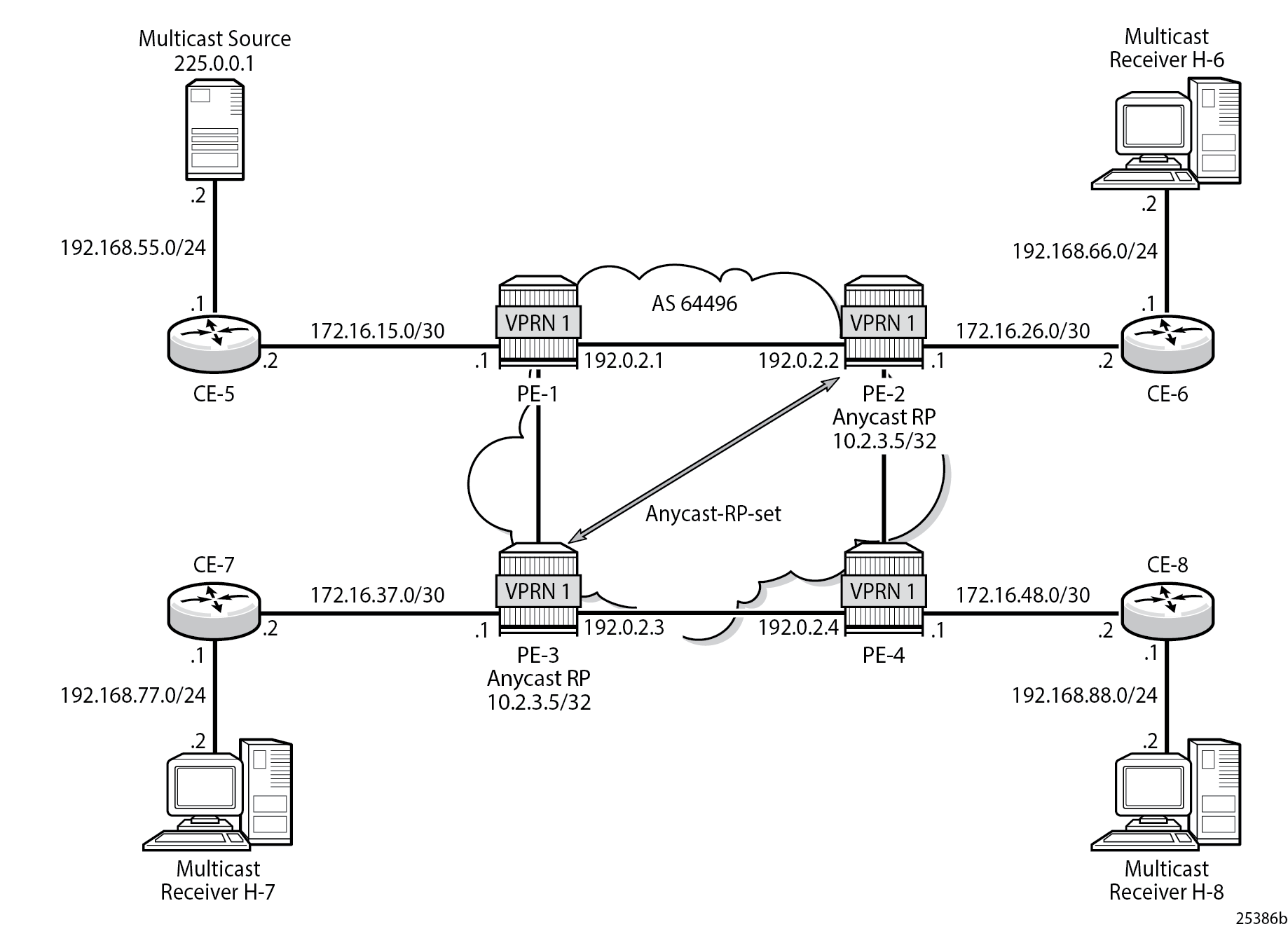
Connected to each PE is a single SR OS router acting as a Customer Edge (CE) router. CE-5 has a single multicast source connected, and PEs 2 to 4 each have a single receiver connected which receives the multicast stream from the source. In this section, each receiver is IGMPv2 capable, and issues IGMPv2 reports. An RP is required by the C-signaling plane to resolve each (*,G) group state into an (S,G) state. In this case, two RPs are chosen to form an Anycast set to resolve each (*,G) group into an (S,G) state.
Multicast traffic from the source group 225.0.0.1 is streamed toward router CE-5. Receivers connected to PE-2, PE-3 and PE-4 are interested in joining this multicast group.
Anycast RP - PE VPRN Configuration
As previously stated, there is a requirement for an RP, as customer multicast signaling is PIM-ASM and IGMPv2.
In this case, an anycast RP is used. This is configured on PE-2 and PE-3, and an anycast set is created.
As each PE contains a CE which is part of the multicast VRF, it is necessary to enable PIM on each interface containing an attachment circuit toward a CE, and to configure the I-PMSI multicast tunnel for the VRF.
The following shows the VPRN configuration for PE-2 containing the RP and anycast RP configuration. The loopback interface "lo1" is used for inter-RP communication:
On PE-2:
configure
    service
        vprn 1
            interface "RP" create
                address 10.2.3.5/32
                loopback
            exit
            interface "lo1" create
                address 10.0.0.2/32
                loopback
            exit
            pim
                interface "int-PE-2-CE-6"
                exit
                interface "RP"
                exit
                interface "lo1"
                exit
                no shutdown
                rp
                    static
                        address 10.2.3.5
                            group-prefix 225.0.0.0/8
                        exit
                    exit
                    anycast 10.2.3.5
                        rp-set-peer 10.0.0.2
                        rp-set-peer 10.0.0.3
                    exit
                exit
            exit
            no shutdown
        exit all
Similarly, the VPRN configuration for PE-3 is:
On PE-3:
configure
    service
        vprn 1
            interface "RP" create
                address 10.2.3.5/32
                loopback
            exit
            interface "lo1" create
                address 10.0.0.3/32
                loopback
            exit
            pim
                interface "int-PE-3-CE-7"
                exit
                interface "RP"
                exit
                interface "lo1"
                exit
                no shutdown
                rp
                    static
                        address 10.2.3.5
                            group-prefix 225.0.0.0/8
                        exit
                    exit
                    anycast 10.2.3.5
                        rp-set-peer 10.0.0.2
                        rp-set-peer 10.0.0.3
                    exit
                exit
            exit
            no shutdown
        exit all
As previously stated, there is a requirement for an RP, as customer multicast signaling is PIM-ASM and IGMPv2.
In this case, an anycast RP is used. This is configured on PE-2 and PE-3, and an anycast set is created.
The anycast address is 10.2.3.5/32 and is created as an interface called "RP" on both PE-2 and PE-3.
An additional loopback interface, called "lo1" is created on each VPRN on PEs containing the anycast address. These are used as source addresses for communication between the routers within the RP set. These addresses are automatically advertised to all PEs as VPN-IPv4 addresses, and are installed in the VRF 1 forwarding table of all PEs containing VPRN 1.
Note: All routers containing RP must have their own loopback address included in the RP set as well as all peer routers.
The multicast group address used for the Inclusive PMSI is chosen to be 239.255.255.1 and must be the same on all PEs for this VPRN instance. This is analogous to the MDT within the Rosen MVPN implementation.
On PE-2:
configure
    service
        vprn 1
            mvpn
                provider-tunnel
                    inclusive
                        pim asm 239.255.255.1
                        exit
                    exit
                exit
            exit
            no shutdown
        exit all
Verify that PIM in the global routing table (GRT) has signaled the I-PMSIs.
For the PE acting as the RP for global PIM:
A:PE-1# show router pim group

===============================================================================
Legend:  A = Active   S = Standby
===============================================================================
PIM Groups ipv4
===============================================================================
Group Address               Type                Spt Bit  Inc Intf       No.Oifs
   Source Address              RP                  State    Inc Intf(S)
-------------------------------------------------------------------------------
239.255.255.1               (*,G)                                       3
   *                           192.0.2.1
239.255.255.1               (S,G)               spt      system         3
   192.0.2.1                   192.0.2.1
239.255.255.1               (S,G)               spt      int-PE-1-PE-2  3
   192.0.2.2                   192.0.2.1
239.255.255.1               (S,G)               spt      int-PE-1-PE-3  3
   192.0.2.3                   192.0.2.1
239.255.255.1               (S,G)               spt      int-PE-1-PE-2  2
   192.0.2.4                   192.0.2.1
-------------------------------------------------------------------------------
Groups : 5
===============================================================================
PE-3 has:
*A:PE-3# show router pim group

===============================================================================
Legend:  A = Active   S = Standby
===============================================================================
PIM Groups ipv4
===============================================================================
Group Address               Type                Spt Bit  Inc Intf       No.Oifs
   Source Address              RP                  State    Inc Intf(S)
-------------------------------------------------------------------------------
239.255.255.1               (*,G)                        int-PE-3-PE-1  1
   *                           192.0.2.1
239.255.255.1               (S,G)               spt      system         2
   192.0.2.3                   192.0.2.1
-------------------------------------------------------------------------------
Groups : 2
===============================================================================
This shows a (S,G) join toward the RP at 192.0.2.1, plus a (*,G) join from RP. These represent the outgoing and incoming PIM interfaces for the VRF.
This results in a series of PIM neighbors through the I-PMSIs within the VRF, which are maintained using PIM hellos.
A:PE-1# show router 1 pim neighbor

===============================================================================
PIM Neighbor ipv4
===============================================================================
Interface               Nbr DR Prty     Up Time       Expiry Time     Hold Time
   Nbr Address
-------------------------------------------------------------------------------
int-PE-1-CE-5           1               0d 00:14:59   0d 00:01:17     105
   172.16.15.2
1-mt-239.255.255.1      1               0d 00:15:35   0d 00:01:44     105
   192.0.2.2
1-mt-239.255.255.1      1               0d 00:15:22   0d 00:01:27     105
   192.0.2.3
1-mt-239.255.255.1      1               0d 00:15:10   0d 00:01:38     105
   192.0.2.4
-------------------------------------------------------------------------------
Neighbors : 4
===============================================================================
Verify PIM RP set on PE-2 (similar for PE-3):
*A:PE-2# show router 1 pim anycast

===============================================================================
PIM Anycast RP Entries ipv4
===============================================================================
Anycast RP                              Anycast RP Peer
-------------------------------------------------------------------------------
10.2.3.5                                10.0.0.2
                                        10.0.0.3
-------------------------------------------------------------------------------
PIM Anycast RP Entries : 2
===============================================================================
Anycast RP - Customer Edge Router Multicast Configuration
Each CE router has a PIM neighbor peer relationship with its nearest PE.
The CE router (CE-5) containing the source has PIM enabled on the interface connected to the source.
On CE-5:
configure
    service
        vprn 1
            pim
                interface "int-CE-5-PE-1"
                exit
                interface "int-CE-5-S-5"
                exit
                no shutdown
                rp
                    static
                        address 10.2.3.5
                            group-prefix 225.0.0.0/8
                        exit
                    exit
                exit
            exit
            no shutdown
        exit all
The CE containing the receivers has IGMP enabled on the interface connected to the receivers.
On CE-6:
configure
    service
        vprn 1
            igmp
                interface "int-CE-6-H-6"
                exit
            exit
            no shutdown
        exit all
Traffic Flow
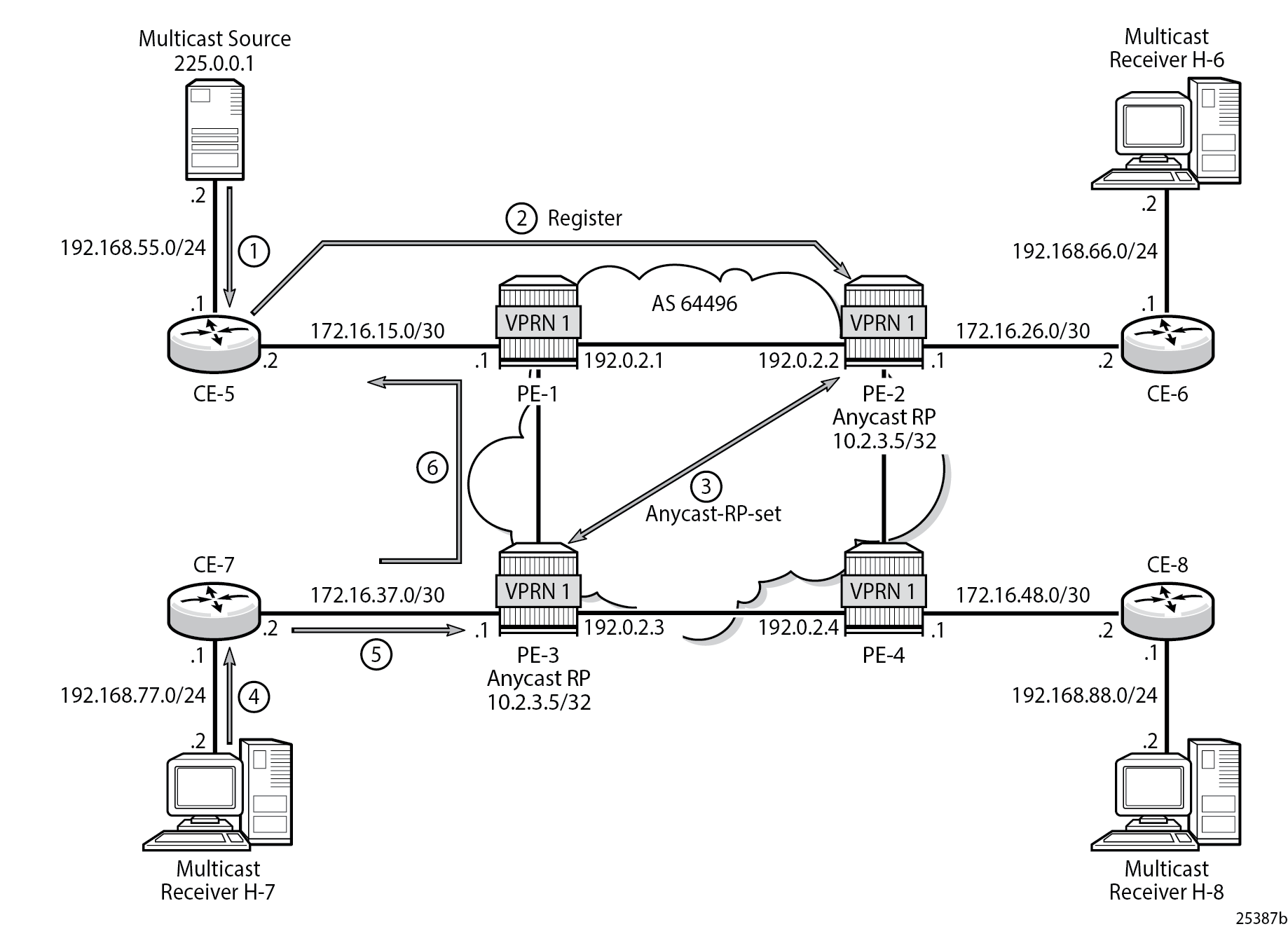
IGMP and PIM Control Messaging Schematic shows the sequence of IGMP and PIM control messaging.
-
The source multicasts a stream with group address 225.0.0.1 toward CE-5.
-
CE-5 matches the group with the group address prefix in the static RP configuration and sends a register message toward the RP.
A:CE-5# show router 1 pim group detail

===============================================================================
PIM Source Group ipv4
===============================================================================
Group Address      : 225.0.0.1
Source Address     : 192.168.55.2
RP Address         : 10.2.3.5
Advt Router        : 192.0.2.5
Flags              :                    Type               : (S,G)
Mode               : sparse
MRIB Next Hop      : 192.168.55.2
MRIB Src Flags     : direct
Keepalive Timer Exp: 0d 00:03:05
Up Time            : 0d 00:12:37        Resolved By        : rtable-u

Up JP State        : Not Joined         Up JP Expiry       : 0d 00:00:00
Up JP Rpt          : Not Joined StarG   Up JP Rpt Override : 0d 00:00:00

Register State     : Pruned             Register Stop Exp  : 0d 00:00:40
Reg From Anycast RP: No

Rpf Neighbor       : 192.168.55.2
Incoming Intf      : int-CE-5-S-5
Outgoing Intf List :

Curr Fwding Rate   : 4815.728 kbps
Forwarded Packets  : 364640             Discarded Packets  : 0
Forwarded Octets   : 358076480          RPF Mismatches     : 0
Spt threshold      : 0 kbps             ECMP opt threshold : 7
Admin bandwidth    : 1 kbps
-------------------------------------------------------------------------------
Groups : 1
===============================================================================
The register message is sent to the nearest RP, the RP with the lowest IGP cost.
When the register is sent through PE-1, it is PE-1 that determines which RP receives the message.
A:PE-1# show router 1 route-table 10.2.3.5/32

===============================================================================
Route Table (Service: 1)
===============================================================================
Dest Prefix[Flags]                            Type    Proto     Age        Pref
      Next Hop[Interface Name]                                    Metric
-------------------------------------------------------------------------------
10.2.3.5/32                                   Remote  BGP VPN   00h02m45s  170
       192.0.2.2 (tunneled)                                         1
-------------------------------------------------------------------------------
No. of Routes: 1
Flags: n = Number of times nexthop is repeated
       B = BGP backup route available
       L = LFA nexthop available
       S = Sticky ECMP requested
===============================================================================
The PE which receives the register is 192.0.2.2 (PE-2). The PIM group status on PE-2 is:
*A:PE-2# show router 1 pim group

===============================================================================
Legend:  A = Active   S = Standby
===============================================================================
PIM Groups ipv4
===============================================================================
Group Address               Type                Spt Bit  Inc Intf       No.Oifs
   Source Address              RP                  State    Inc Intf(S)
-------------------------------------------------------------------------------
225.0.0.1                   (S,G)                        1-mt-239.255.* 0
   192.168.55.2                10.2.3.5
-------------------------------------------------------------------------------
Groups : 1
===============================================================================
* indicates that the corresponding row element may have been truncated.
This shows that RP is aware of the (S,G) status of the group 225.0.0.1, and becomes a root of a shared tree for this group. The Outgoing Interface List (OIL) is empty.
-
PE-2 now sends a register message to all other RPs within the anycast set, in this case to PE-3 (which has VPRN 1 containing address 10.0.0.3).
The PIM status of the group 225.0.0.1 on PE-3 is:
*A:PE-3# show router 1 pim group

===============================================================================
Legend:  A = Active   S = Standby
===============================================================================
PIM Groups ipv4
===============================================================================
Group Address               Type                Spt Bit  Inc Intf       No.Oifs
   Source Address              RP                  State    Inc Intf(S)
-------------------------------------------------------------------------------
225.0.0.1                   (S,G)                        1-mt-239.255.* 0
   192.168.55.2                10.2.3.5
-------------------------------------------------------------------------------
Groups : 1
===============================================================================
* indicates that the corresponding row element may have been truncated.
Now both PEs within the RP set for VPRN have an (S,G) state for 225.0.0.1.
-
The receiver H-7 wants to join the group 225.0.0.1, and sends in an IGMPv2 report toward CE-7. CE-7 recognizes the report, but has no PIM state for this group.
-
CE-7 sends a PIM join toward the RP, in this case the nearest RP is PE-3.
PE-3 already has (S,G) state for this group, so forwards traffic toward receiver H-7.
-
CE-7 does a Reverse Path Forwarding (RPF) lookup of the source address in the route table, and issues a PIM join toward the source.
The join is propagated across the provider network toward PE-1, which is the resolved RPF next hop for the source.
*A:CE-7# show router 1 pim group type sg detail

===============================================================================
PIM Source Group ipv4
===============================================================================
Group Address      : 225.0.0.1
Source Address     : 192.168.55.2
RP Address         : 10.2.3.5
Advt Router        :
Flags              : spt                Type               : (S,G)
Mode               : sparse
MRIB Next Hop      : 172.16.37.1
MRIB Src Flags     : remote
Keepalive Timer Exp: 0d 00:02:37
Up Time            : 0d 00:00:54        Resolved By        : rtable-u

Up JP State        : Joined             Up JP Expiry       : 0d 00:00:05
Up JP Rpt          : Not Pruned         Up JP Rpt Override : 0d 00:00:00

Register State     : No Info
Reg From Anycast RP: No

Rpf Neighbor       : 172.16.37.1
Incoming Intf      : int-CE-7-PE-3
Outgoing Intf List : int-CE-7-H-7

Curr Fwding Rate   : 4811.800 kbps
Forwarded Packets  : 32917              Discarded Packets  : 0
Forwarded Octets   : 32324494           RPF Mismatches     : 0
Spt threshold      : 0 kbps             ECMP opt threshold : 7
Admin bandwidth    : 1 kbps
-------------------------------------------------------------------------------
Groups : 1
===============================================================================
The join is received by CE-5, which contains the subnet of the source.
CE-5 now recognizes the multicast group as a valid stream. CE-5 becomes the root of the shortest path tree for the group.
A:CE-5# show router 1 pim group

===============================================================================
Legend:  A = Active   S = Standby
===============================================================================
PIM Groups ipv4
===============================================================================
Group Address               Type                Spt Bit  Inc Intf       No.Oifs
   Source Address              RP                  State    Inc Intf(S)
-------------------------------------------------------------------------------
225.0.0.1                   (S,G)               spt      int-CE-5-S-5   1
   192.168.55.2                10.2.3.5
-------------------------------------------------------------------------------
Groups : 1
===============================================================================
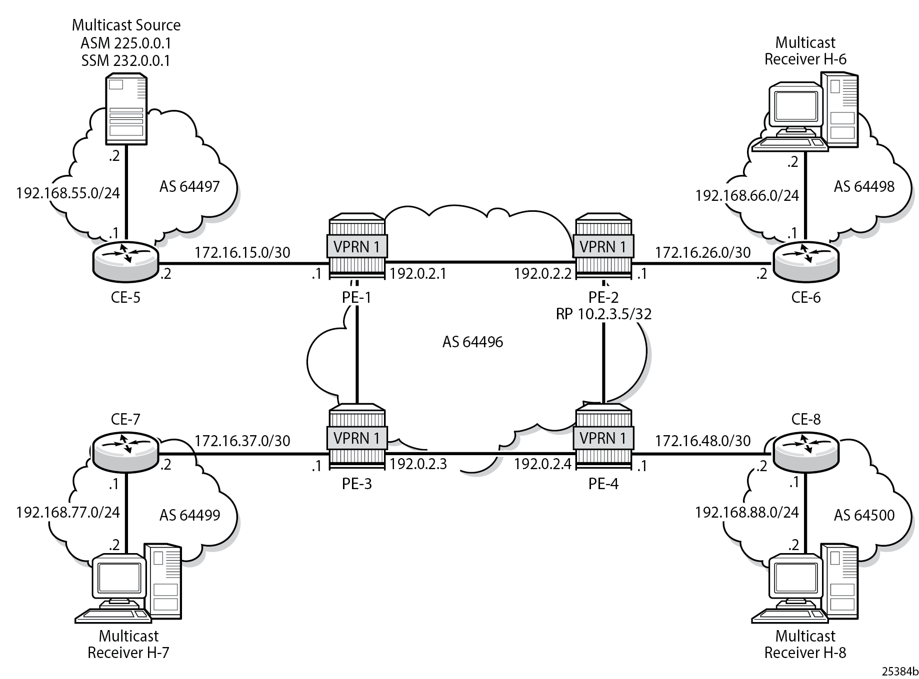
PIM Source Specific Multicasting
There is no requirement for an RP, because customer multicast signaling is PIM-SSM. The multicast group address used for the PMSI must be the same on all PEs for this VPRN instance.
The following shows the VPRN configuration for PIM and MVPN for PE-1.
On PE-1:
configure
    service
        vprn 1
            pim
                interface "int-PE-1-CE-5"
                exit
                no shutdown
            exit
            mvpn
                provider-tunnel
                    inclusive
                        pim asm 239.255.255.1
                        exit
                    exit
                exit
            exit
            no shutdown
        exit all
There is a similar configuration required for each of the other PEs. Verify that PIM in the GRT has signaled the I-PMSIs.
For the PE acting as the RP for global PIM:
A:PE-1# show router pim group

===============================================================================
Legend:  A = Active   S = Standby
===============================================================================
PIM Groups ipv4
===============================================================================
Group Address               Type                Spt Bit  Inc Intf       No.Oifs
   Source Address              RP                  State    Inc Intf(S)
-------------------------------------------------------------------------------
239.255.255.1               (*,G)                                       3
   *                           192.0.2.1
239.255.255.1               (S,G)               spt      system         3
   192.0.2.1                   192.0.2.1
239.255.255.1               (S,G)               spt      int-PE-1-PE-2  3
   192.0.2.2                   192.0.2.1
239.255.255.1               (S,G)               spt      int-PE-1-PE-3  3
   192.0.2.3                   192.0.2.1
239.255.255.1               (S,G)               spt      int-PE-1-PE-2  2
   192.0.2.4                   192.0.2.1
-------------------------------------------------------------------------------
Groups : 5
===============================================================================
PE-3 has:
A:PE-3# show router pim group

===============================================================================
Legend:  A = Active   S = Standby
===============================================================================
PIM Groups ipv4
===============================================================================
Group Address               Type                Spt Bit  Inc Intf       No.Oifs
   Source Address              RP                  State    Inc Intf(S)
-------------------------------------------------------------------------------
239.255.255.1               (*,G)                        int-PE-3-PE-1  1
   *                           192.0.2.1
239.255.255.1               (S,G)               spt      system         2
   192.0.2.3                   192.0.2.1
-------------------------------------------------------------------------------
Groups : 2
===============================================================================
This shows a (S,G) join toward the RP at 192.0.2.1, plus a (*,G) join from RP. These represent the outgoing and incoming PIM interfaces for the VRF.
This results in a series of PIM neighbors through the I-PMSIs within the VRF, which are maintained using PIM hellos.
A:PE-1# show router 1 pim neighbor

===============================================================================
PIM Neighbor ipv4
===============================================================================
Interface               Nbr DR Prty     Up Time       Expiry Time     Hold Time
   Nbr Address
-------------------------------------------------------------------------------
int-PE-1-CE-5           1               0d 00:21:55   0d 00:01:21     105
   172.16.15.2
1-mt-239.255.255.1      1               0d 00:22:30   0d 00:01:18     105
   192.0.2.2
1-mt-239.255.255.1      1               0d 00:22:17   0d 00:01:31     105
   192.0.2.3
1-mt-239.255.255.1      1               0d 00:22:06   0d 00:01:42     105
   192.0.2.4
-------------------------------------------------------------------------------
Neighbors : 4
===============================================================================
PIM SSM - Customer Edge Router Multicast Configuration
Each CE router has a PIM neighbor peer relationship with its nearest PE.
The CE router (CE-5) containing the source has PIM enabled on the interface connected to the source.
On CE-5:
configure
    service
        vprn 1
            pim
                interface "int-CE-5-PE-1"
                exit
                interface "int-CE-5-S-5"
                exit
                no shutdown
            exit
            no shutdown
        exit all
The CE containing the receivers has IGMP enabled on the interface connected to the receivers and PIM on the interface facing the PE.
On CE-6:
configure
    service
        vprn 1
            igmp
                interface "int-CE-6-H-6"
                exit
            exit
            pim
                interface "int-CE-6-PE-2"
                exit
                no shutdown
            exit
            static-route-entry 192.168.55.0/24
                next-hop 172.16.26.1
                    no shutdown
                exit
            exit
            no shutdown
        exit all
Traffic Flow
The source multicasts a stream with group address 232.0.0.1 toward CE-5. When there is no receiver interested in the group at this time, there are no outgoing interfaces, so the Outgoing Interface List (OIL) is empty.
A:CE-5# show router 1 pim group

===============================================================================
Legend:  A = Active   S = Standby
===============================================================================
PIM Groups ipv4
===============================================================================
Group Address               Type                Spt Bit  Inc Intf       No.Oifs
   Source Address              RP                  State    Inc Intf(S)
-------------------------------------------------------------------------------
---snip---
232.0.0.1                   (S,G)                        int-CE-5-S-5   0
   192.168.55.2
-------------------------------------------------------------------------------
Groups : 2
===============================================================================
The receiver H-6 wants to join the group 232.0.0.1, and so sends in an IGMPv3 report toward CE-6. CE-6 recognizes the report, which contains the source 192.168.55.2 in the include filter list.
*A:CE-6# show router 1 igmp group
===============================================================================
IGMP Interface Groups
===============================================================================

(192.168.55.2,232.0.0.1)                                  UpTime: 0d 00:00:58
    Fwd List  : int-CE-6-H-6
-------------------------------------------------------------------------------
Entries : 1
===============================================================================
IGMP Host Groups
===============================================================================
No Matching Entries
===============================================================================
IGMP SAP Groups
===============================================================================
No Matching Entries
===============================================================================
IGMP SLA Profile Instance Groups
===============================================================================
No Matching Entries
===============================================================================
CE-6 does a RPF lookup of the source address in the route table, and issues a PIM join toward the source.
The join is propagated across the provider network, toward PE-1 which is the resolved RPF next hop for the source.
A:PE-1# show router 1 pim group detail

===============================================================================
PIM Source Group ipv4
===============================================================================
Group Address      : 232.0.0.1
Source Address     : 192.168.55.2
RP Address         : 0
Advt Router        : 172.16.15.2
Flags              :                    Type               : (S,G)
Mode               : sparse
MRIB Next Hop      : 172.16.15.2
MRIB Src Flags     : remote
Keepalive Timer    : Not Running
Up Time            : 0d 00:01:08        Resolved By        : rtable-u

Up JP State        : Joined             Up JP Expiry       : 0d 00:00:51
Up JP Rpt          : Not Joined StarG   Up JP Rpt Override : 0d 00:00:00

Register State     : No Info
Reg From Anycast RP: No

Rpf Neighbor       : 172.16.15.2
Incoming Intf      : int-PE-1-CE-5
Outgoing Intf List : 1-mt-239.255.255.1

Curr Fwding Rate   : 4811.800 kbps
Forwarded Packets  : 41936              Discarded Packets  : 0
Forwarded Octets   : 41181152           RPF Mismatches     : 0
Spt threshold      : 0 kbps             ECMP opt threshold : 7
Admin bandwidth    : 1 kbps
-------------------------------------------------------------------------------
Groups : 1
===============================================================================
The outgoing interface is the I-PMSI: 1-mt-239.255.255.1.
The join is received by CE-5, which contains the subnet of the source.
CE-5 now recognizes the multicast group as a valid stream. CE-5 becomes the root of the shortest path tree for the group.
A:CE-5# show router 1 pim group

===============================================================================
Legend:  A = Active   S = Standby
===============================================================================
PIM Groups ipv4
===============================================================================
Group Address               Type                Spt Bit  Inc Intf       No.Oifs
   Source Address              RP                  State    Inc Intf(S)
-------------------------------------------------------------------------------
232.0.0.1                   (S,G)                        int-CE-5-S-5   1
   192.168.55.2
-------------------------------------------------------------------------------
Groups : 1
===============================================================================
PE BGP Auto-Discovery
Discovery of Multicast-enabled Virtual Private Networks (MVPNs) can also be achieved using BGP. To this end, any PE that is a member of a multicast VPN advertises this using a BGP multi-protocol Network Layer Reachability Information (NLRI) update that is sent to all PEs within the AS. This update contains an intra-AS I-PMSI Auto-Discovery route type, also known as an Intra-AD. These use a dedicated address family mvpn-ipv4 so each PE must be configured to originate and accept such updates. The following needs to be modified in the bgp context for all PE nodes:
On all PEs:
configure
    router
        bgp
            group "INTERNAL"
                family vpn-ipv4 mvpn-ipv4
            exit all
This is achieved in the GRT within the bgp context.
This allows each BGP speaker to advertise its capabilities within a BGP Open message.
The following BGP summary on PE-1 shows that BGP sessions are established between the PEs for address families VPN-IPv4 and MVPN-IPv4 in the base routing instance:
*A:PE-1# show router bgp summary all

===============================================================================
BGP Summary
===============================================================================
Legend : D - Dynamic Neighbor
===============================================================================
Neighbor
Description
ServiceId          AS PktRcvd InQ  Up/Down   State|Rcv/Act/Sent (Addr Family)
                      PktSent OutQ
-------------------------------------------------------------------------------
192.0.2.2
Def. Inst       64496       4    0 00h00m26s 0/0/0 (VpnIPv4)
                            6    0           0/0/0 (MvpnIPv4)
192.0.2.3
Def. Inst       64496       4    0 00h00m24s 0/0/0 (VpnIPv4)
                            6    0           0/0/0 (MvpnIPv4)
192.0.2.4
Def. Inst       64496       4    0 00h00m23s 0/0/0 (VpnIPv4)
                            6    0           0/0/0 (MvpnIPv4)

172.16.15.2
1               64497      86    0 00h38m27s 1/1/1 (IPv4)
                           86    0
-------------------------------------------------------------------------------
BGP Auto-Discovery - PE VPRN Multicast Configuration
Each PE contains a CE which is part of the multicast VRF, so it is necessary to enable PIM on each interface containing an attachment circuit toward a CE, and to configure the I-PMSI multicast tunnel for the VRF.
For the BGP routes to be accepted into the VRF, a route-target community is required (vrf-target). This is configured in the configure service vprn 1 mvpn context and, in this case, is set to the same value as the unicast vrf-target, the vrf-target community in the configure service vprn 1 bgp-ipvpn mpls vrf-target context.
On each PE, the mvpn context of the VPRN instance is configured as follows:
On PE-2:
configure
    service
        vprn 1
            mvpn
                auto-discovery
                provider-tunnel
                    inclusive
                        pim asm 239.255.255.1
                        exit
                    exit
                exit
                vrf-target unicast
                exit
            exit
            no shutdown
        exit all
The multicast group address used for the PMSI must be the same on all PEs for this VPRN instance.
The presence of auto-discovery initiates BGP updates between the PEs that contain an MVPN, such as Intra-AD MVPN routes, are generated and advertised to each peer
*A:PE-1# show router bgp routes mvpn-ipv4
===============================================================================
 BGP Router ID:192.0.2.1        AS:64496       Local AS:64496
===============================================================================
 Legend -
 Status codes  : u - used, s - suppressed, h - history, d - decayed, * - valid
                 l - leaked, x - stale, > - best, b - backup, p - purge
 Origin codes  : i - IGP, e - EGP, ? - incomplete

===============================================================================
BGP MVPN-IPv4 Routes
===============================================================================
Flag  RouteType                   OriginatorIP           LocalPref   MED
      RD                          SourceAS               Path-Id     IGP Cost
      Nexthop                     SourceIP                           Label
      As-Path                     GroupIP
-------------------------------------------------------------------------------
u*>i  Intra-Ad                    192.0.2.2              100         0
      64496:1                     -                      None        -
      192.0.2.2                   -
      No As-Path                  -
u*>i  Intra-Ad                    192.0.2.3              100         0
      64496:1                     -                      None        -
      192.0.2.3                   -
      No As-Path                  -
u*>i  Intra-Ad                    192.0.2.4              100         0
      64496:1                     -                      None        -
      192.0.2.4                   -
      No As-Path                  -
-------------------------------------------------------------------------------
Routes : 3
===============================================================================
This shows that PE-1 has received an Intra-AD route from each of the other PEs, each of which has multicast VPRN 1 configured.
Examining the intra-AD routes received from PE-2 shows that the route-target community matches the unicast VRF-target (64496:1), and also that the PMSI tree has a multicast group address of 239.255.255.1, which matches the I-PMSI group configuration on PE-1.
*A:PE-1# show router bgp routes mvpn-ipv4 type intra-ad originator-ip 192.0.2.2 detail
===============================================================================
 BGP Router ID:192.0.2.1        AS:64496       Local AS:64496
===============================================================================
 Legend -
 Status codes  : u - used, s - suppressed, h - history, d - decayed, * - valid
                 l - leaked, x - stale, > - best, b - backup, p - purge
 Origin codes  : i - IGP, e - EGP, ? - incomplete

===============================================================================
BGP MVPN-IPv4 Routes
===============================================================================
Original Attributes

Route Type     : Intra-Ad
Route Dist.    : 64496:1
Originator IP  : 192.0.2.2
Nexthop        : 192.0.2.2
Path Id        : None
From           : 192.0.2.2
Res. Nexthop   : 0.0.0.0
Local Pref.    : 100                    Interface Name : NotAvailable
Aggregator AS  : None                   Aggregator     : None
Atomic Aggr.   : Not Atomic             MED            : 0
AIGP Metric    : None                   IGP Cost       : n/a
Connector      : None
Community      : no-export target:64496:1
Cluster        : No Cluster Members
Originator Id  : None                   Peer Router Id : 192.0.2.2
Flags          : Used Valid Best IGP
Route Source   : Internal
AS-Path        : No As-Path
Route Tag      : 0
Neighbor-AS    : n/a
DB Orig Val    : N/A                    Final Orig Val : N/A
Source Class   : 0                      Dest Class     : 0
Add Paths Send : Default
Last Modified  : 00h01m39s
VPRN Imported  : 1
-------------------------------------------------------------------------------
PMSI Tunnel Attributes :
Tunnel-type    : PIM-SM Tree
Flags          : Type: RNVE(0) BM: 0 U: 0 Leaf: not required
MPLS Label     : 0
Sender         : 192.0.2.2              P-Group        : 239.255.255.1
-------------------------------------------------------------------------------
---snip---

-------------------------------------------------------------------------------
Routes : 1
===============================================================================
Verify that PIM in the GRT has signaled the I-PMSIs.
For the PE acting as the RP for global PIM:
*A:PE-1# show router pim group

===============================================================================
Legend:  A = Active   S = Standby
===============================================================================
PIM Groups ipv4
===============================================================================
Group Address               Type                Spt Bit  Inc Intf       No.Oifs
   Source Address              RP                  State    Inc Intf(S)
-------------------------------------------------------------------------------
239.255.255.1               (*,G)                                       3
   *                           192.0.2.1
239.255.255.1               (S,G)               spt      system         3
   192.0.2.1                   192.0.2.1
239.255.255.1               (S,G)               spt      int-PE-1-PE-2  3
   192.0.2.2                   192.0.2.1
239.255.255.1               (S,G)               spt      int-PE-1-PE-3  3
   192.0.2.3                   192.0.2.1
239.255.255.1               (S,G)               spt      int-PE-1-PE-2  2
   192.0.2.4                   192.0.2.1
-------------------------------------------------------------------------------
Groups : 5
===============================================================================
This shows an incoming (S,G) join from all other PEs within the multicast VRF, plus an outgoing (*,G) join to the same PEs.
PE-3 has the following PIM groups:
*A:PE-3# show router pim group

===============================================================================
Legend:  A = Active   S = Standby
===============================================================================
PIM Groups ipv4
===============================================================================
Group Address               Type                Spt Bit  Inc Intf       No.Oifs
   Source Address              RP                  State    Inc Intf(S)
-------------------------------------------------------------------------------
239.255.255.1               (*,G)                        int-PE-3-PE-1  1
   *                           192.0.2.1
239.255.255.1               (S,G)               spt      system         2
   192.0.2.3                   192.0.2.1
-------------------------------------------------------------------------------
Groups : 2
===============================================================================
This shows a (S,G) join toward the RP at 192.0.2.1, plus a (*,G) join from RP. These represent the outgoing and incoming PIM interfaces for the VRF.
This results in a series of PIM neighbors through the I-PMSIs within the VRF. The neighbors were discovered using BGP (not with PIM as per Rosen MVPN), therefore, there are no PIM hellos exchanged.
*A:PE-1# show router 1 pim neighbor

===============================================================================
PIM Neighbor ipv4
===============================================================================
Interface               Nbr DR Prty     Up Time       Expiry Time     Hold Time
   Nbr Address
-------------------------------------------------------------------------------
int-PE-1-CE-5           1               0d 00:32:28   0d 00:01:18     105
   172.16.15.2
1-mt-239.255.255.1      1               0d 00:01:53   never           65535
   192.0.2.2
1-mt-239.255.255.1      1               0d 00:01:53   never           65535
   192.0.2.3
1-mt-239.255.255.1      1               0d 00:01:52   never           65535
   192.0.2.4
-------------------------------------------------------------------------------
Neighbors : 4
===============================================================================
BGP Auto-Discovery - Customer Signaling Domain
The customer signaling is independent from the provider PE discovery mechanism, therefore, all of the customer signaling techniques described when using PIM for auto-discovery within provider domain are also applicable when using BGP for auto-discovery, namely
-
PIM Any Source Multicasting with RP at the provider PE
-
PIM Any Source Multicasting with Anycast RP at the provider PE
-
PIM Source Specific Multicasting
Data Path Using Selective PMSI
When a configurable data threshold for a multicast group has been exceeded, multicast traffic across the provider network can be switched to a Selective PMSI (S-PMSI).
This has to be configured as a separate group and must contain a threshold which, if exceeded, sees a new PMSI signaled by the PE nearest the source, and traffic switched onto the S-PMSI.
On PE-1:
configure
    service
        vprn 1
            mvpn
                provider-tunnel
                    inclusive
                        pim asm 239.255.255.1
                        exit
                    exit
                    selective
                        data-threshold 232.0.0.0/8 1
                        pim-ssm 232.255.1.0/24
                    exit
                exit
            exit
            no shutdown
        exit all
This shows that when the traffic threshold for multicast groups covered by the range 232.0.0.0/8 exceeds 1 kb/s between a pair of PEs, then an S-PMSI is signaled between the PEs. This is a separate multicast tunnel over which traffic in that group now flows.
*A:PE-1# show router 1 pim s-pmsi detail

===============================================================================
PIM Selective provider tunnels
===============================================================================
Md Source Address  : 192.0.2.1          Md Group Address   : 232.255.1.0
Number of VPN SGs  : 1                  Uptime             : 0d 00:00:59
MT IfIndex         : 5798468
Multistream-Id     : 0

VPN Group Address  : 232.0.0.1
VPN Source Address : 192.168.55.2
State              : TX Joined          Mdt Threshold      : 1
Join Timer         : 0d 00:00:01        Holddown Timer     : 0d 00:00:00
===============================================================================
PIM Selective provider tunnels Interfaces : 1
===============================================================================
In this example, the (S,G) group is (192.168.55.2, 232.0.0.1). When the data rate has exceeded the configured MDT threshold of 1 kb/s, a new provider tunnel with a group address of 232.255.1.0 has been signaled and now carries the multicast stream.
The TX Joined state indicates that the S-PMSI has been sourced at this PE -PE-1.
Comparing this to PE-3, where a receiver is connected through a CE indicates that it has received a join to connect the S-PMSI.
*A:PE-3# show router 1 pim s-pmsi detail

===============================================================================
PIM Selective provider tunnels
===============================================================================
Md Source Address  : 192.0.2.1          Md Group Address   : 232.255.1.0
Number of VPN SGs  : 1                  Uptime             : 0d 00:01:02
MT IfIndex         : 5806657            Egress Fwding Rate : 4815.728 kbps
Multistream-Id     : 0

VPN Group Address  : 232.0.0.1
VPN Source Address : 192.168.55.2
State              : RX Joined
Expiry Timer       : 0d 00:02:58
===============================================================================
PIM Selective provider tunnels Interfaces : 1
===============================================================================
Conclusion
This chapter provides configuration on how to configure multicast within a VPRN with NG MVPN techniques. Specifically, discovery of multicast VPNs using PIM and BGP auto-discovery mechanisms are described with a number of ASM and SSM signaling techniques within the customer domain.