Rosen MVPN Core Diversity
This chapter provides information about Rosen multicast virtual private network (MVPN) core diversity.
Topics in this chapter include:
Applicability
This chapter was initially written for SR OS Release 13.0.R4, using Rosen MVPN. The CLI in the current edition is based on SR OS Release 23.10.R1.
Default multicast distribution trees (MDTs) for each virtual private routed network (VPRN) are signaled using protocol independent multicasting (PIM) and auto-discovery uses border gateway protocol multicast distribution tree sub-address family indicator (BGP MDT-SAFI) network layer routing.
Overview
This chapter describes a service provider core network used by multiple content providers to deliver multicast services to multiple customers using Rosen MVPN. If the same set of PEs is used to deliver the MVPN, the MDTs are all routed across the same paths between the set of PEs. Because each MDT is signaled using PIM, and the source of all MDTs is the system address of the PE, the path to this source is the same.
Each remote PE then sends a PIM join toward this PE with its source address set to the system address. For multiple VPNs between the same set of PEs, the MDT follows the same path.
If there is a requirement to deliver content from each content provider across different MVPNs that use diversely routed MDTs, multiple IGP instances can be used: up to three different instances of IGP, OSPF or ISIS, can exist. In this chapter, two instances of OSPF are used to create incongruent topologies providing isolation between the MDTs of two different MVPNs: a default OSPF instance and OSPF instance 1. A separate /32 loopback address can be used as the MDT source address that is advertised in the non-default IGP, which can also be used as the BGP next hop for labeled IPv4 routes representing the customer source addresses.
Knowledge of multi-protocol BGP (MP-BGP) and RFC 4364, BGP/MPLS IP VPNs, is assumed throughout this chapter, as well as the original RFC 6037.
All PEs within an MVPN create a default MDT with their own system address as the source. Auto-discovery of PEs within a Rosen MVPN is achieved using the BGP route type of multicast data tree subsequent address family identifier (MDT-SAFI). Each PE originates an MDT-SAFI route update per MVPN. This route advertises the presence of the MVPN on a specific PE.
Each MDT-SAFI update contains attributes, including the following:
Route distinguisher
Route target extended community
MDT source address (usually the system address)
Group address of MDT
Upon receipt of an MDT-SAFI route update, each remote PE accepts or rejects the route based on the route target extended community value. If the route is accepted, a remote PE sends a PIM (S,G) join to this local PE. The (S,G) values are taken from the MDT-SAFI. The set of MDTs extend the c-multicast data tree across the MVPN and form PIM adjacencies between PEs within the MVPN. The neighbor address across the set of PIM-enabled tunnels is the default MDT source address, usually the system address.
When established, the default MDT is used to transport c-multicast PIM signaling between PEs.
If a source S, of a c-multicast group G, is connected to a sender PE, the route to the source is advertised to remote PEs as a BGP-labeled VPN-IPv4 route.
Therefore, an (S,G) join toward this source at a remote PE performs a reverse path forwarding (RPF) look-up of the unicast VRF table to find a suitable PIM-enabled interface. The next hop needs be resolved to the MDT source address of the sender PE. A PIM join must now be forwarded toward the sender PE that has a PIM neighbor that matches the next hop for this route, the system address of the sender PE. This is the default MDT.
The system address is a significant address in this process. Any other VPRN that uses the same set of PEs also signals a set of default MDTs using a different group address, so they follow the same path between PEs across the provider network.
Core Diversity Schematic shows an example of core diversity; multicast sources provided by two separate content providers are connected to a provider network. There is a requirement to provide topology diversity so that the default MDTs between the same PEs are routed across different paths within the core.
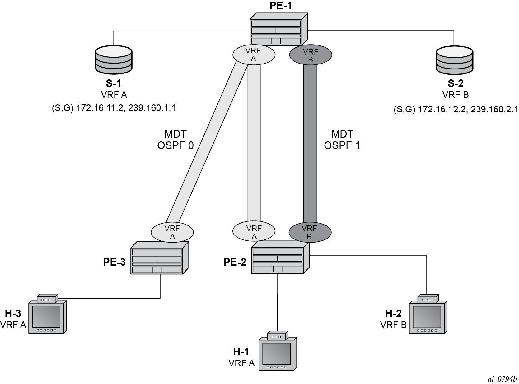
Content servers from two separate content providers are connected to PE-1 with directly connected multicast sources. For simplicity, this example uses only a single multicast group for provider S-1 and S-2.
Source S-1 is reachable via VRF A and source S-2 is reachable via VRF B.
Topology isolation for the multicast data trees of each VPRN can be provided by using two separate IGP instances; in this case, OSPF instances. Multi-instance IS-IS could also be used.
Core Diversity Network shows a schematic of the full network, including the c-multicast groups.
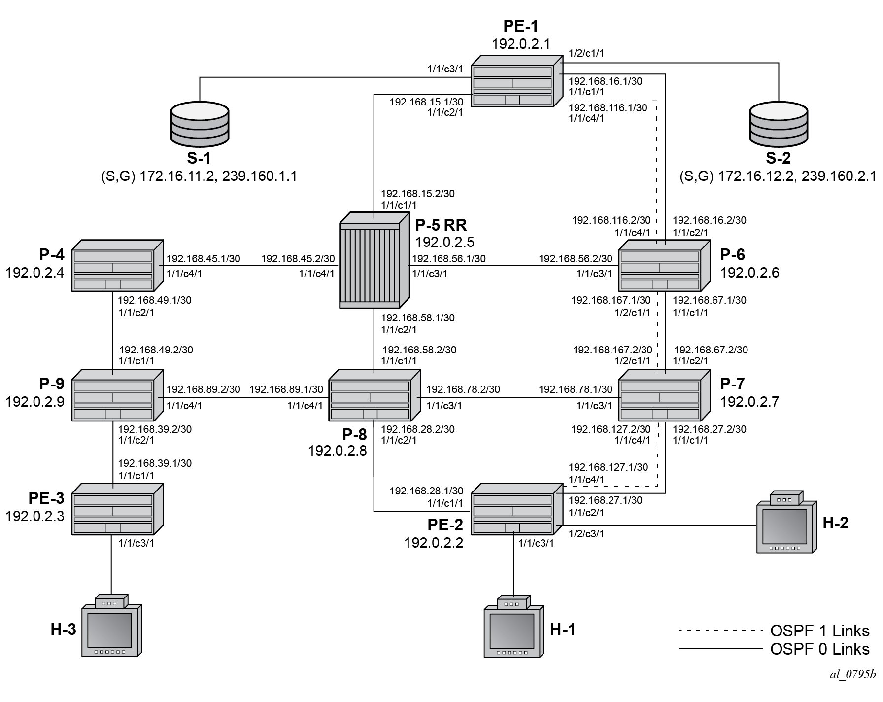
All routers have interfaces in the OSPF base instance (instance 0) and routers interconnected by the dotted lines have interfaces in both the base instance and OSPF 1.
Core Diversity Network shows the extent of the OSFP base instance within the core network.
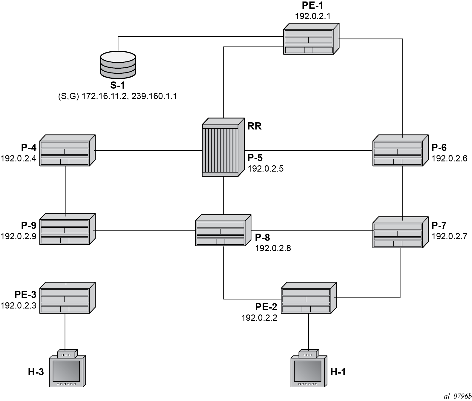
In this case, assume that the shortest path between PE-1 and PE-2 is the path via P-5 and P-8.
Similarly, Core Diversity Network - OSPF Instance 1 shows the extent of OSPF instance 1.
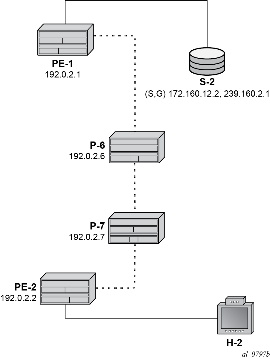
The only path available between PE-1 and PE-2 is now completely diverse from the shortest path advertised between the same pair of PEs in the base OSPF instance.
Therefore, for any MDT to be signaled across the OSFP 1 topology, only addresses advertised within OSPF 1 must be used. As previously stated, the system address is used as the default MDT source address. This system address is not advertised within the OSPF 1 topology, so a replacement /32 loopback address is used as the default MDT source address within OSPF 1.
VPN-IPv4 routes that may represent a customer multicast source address should be reachable via the default MDT. In the non-default topology, the c-multicast signaling across the MVPN must resolve the c-multicast route via the MDT, which has its root at the non-default /32 loopback. Therefore, the VPN-IPv4 prefix representing the possible source routes needs to be advertised containing the non-default /32 loopback.
This can be achieved in one of two ways:
Use a route policy at the advertising PE that changes the BGP next hop to match the MDT source address for non-default topology MDTs.
Use the BGP connector attribute for all VPN-IPv4 route prefixes within a multicast VPRN that has auto-discovery set to MDT-SAFI. The connector attribute contains the MDT source address within the originator field.
This chapter describes the use of the connector attribute.
If the default IGP instance is used, the BGP next hop of the VPN-IPv4 route matches the source address of the default MDT.
Therefore, if a second /32 loopback is used that replaces the system address as MDT source address and also as the next hop for source address RPF look-up, the loopback could be advertised within the non-default IGP instance, and the paths between the PEs would follow this topology.
Core diversity is achieved by configuring the following steps:
Configuring multiple OSPF instances, as shown in Core Diversity Network — Base OSPF and Core Diversity Network - OSPF Instance 1, and including the appropriate interfaces. This includes a separate loopback address per instance.
Configuring separate VPRNs with their own MDTs using BGP MDT-SAFI auto-discovery and PIM signaling across the appropriate PEs.
Configuring the VPRN that uses the base OSPF instance to use the system address as the source addresses for the MDTs (this is default behavior).
Configuring a separate loopback (/32) address that is advertised within OSFP instance 1 only.
Configuring the VPRN that uses the OSPF instance 1 to use the separate loopback system address as the source addresses for the MDTs.
Ensuring the unicast route that represents the c-source address is advertised as a VPN-IPv4 route and has a BGP connector attribute that contains an address that matches the MDT source address of the originating PE.
Configuration
The following configuration tasks must be completed as a prerequisite:
Full mesh OSPF base instance between each of the nodes. However, IS-IS could also be used for any or all of the IGP instances.
Link-layer LDP between each P and PE router.
PIM enabled on each router network interface.
Global BGP Configuration
The first step is to configure an iBGP session between each of the PEs and the route reflector (P-5) shown in Core Diversity Network. The address families negotiated between the iBGP peers are vpn-ipv4, for unicast routing, and mdt-safi for multicast routing.
The iBGP configuration for PE-1 is the following:
# on PE-1
configure
    router
        autonomous-system 64496
        bgp
            group "INTERNAL"
                family vpn-ipv4 mdt-safi
                type internal
                neighbor 192.0.2.5
            exit
        exit
    exit all
The configuration for the other PE nodes is the same.
P-5 is the route reflector for PE-1, PE-2, and PE-3, as follows:
# on P-5
configure
    router
        autonomous-system 64496
        bgp
            cluster 0.0.0.1
            group "RR_CLIENTS"
                family vpn-ipv4 mdt-safi
                type internal
                neighbor 192.0.2.1
                exit
                neighbor 192.0.2.2
                exit
                neighbor 192.0.2.3
                exit
            exit
        exit
    exit all
On PE-1, verify that the BGP session with the route reflector on P-5 is established with address families mdt-safi and vpn-ipv4 capabilities negotiated:
*A:PE-1# show router bgp summary
===============================================================================
 BGP Router ID:192.0.2.1        AS:64496       Local AS:64496
===============================================================================
BGP Admin State         : Up          BGP Oper State              : Up
Total Peer Groups       : 1           Total Peers                 : 1
Total VPN Peer Groups   : 0           Total VPN Peers             : 0
Current Internal Groups : 1           Max Internal Groups         : 1
Total BGP Paths         : 26          Total Path Memory           : 9568
---snip---
===============================================================================
BGP Summary
===============================================================================
Legend : D - Dynamic Neighbor
===============================================================================
Neighbor
Description
                   AS PktRcvd InQ  Up/Down   State|Rcv/Act/Sent (Addr Family)
                      PktSent OutQ
-------------------------------------------------------------------------------
192.0.2.5
                64496       4    0 00h00m09s 0/0/0 (VpnIPv4)
                            4    0           0/0/0 (MdtSafi)
-------------------------------------------------------------------------------
Configuring VPRN on PEs
There are two VPRNs:
VPRN 1 using the base instance OSPF topology. This is present on PE-1, PE-2, and PE-3.
VPRN 2 using OSPF instance 1. This is present on PE-1 and PE-2.
The following output displays the configuration for VPRN 1 for the sender PE-1.
# on PE-1
configure
    service
        vprn 1 name "VPRN 1" customer 1 create
            interface "int-PE-1-S-1" create
                address 172.16.11.1/24
                sap 1/1/c3/1 create
                exit
            exit
            bgp-ipvpn
                mpls
                    auto-bind-tunnel
                        resolution-filter
                            ldp
                        exit
                        resolution filter
                    exit
                    route-distinguisher 64496:1
                    vrf-target target:64496:1
                    no shutdown
                exit
            exit
            pim
                apply-to all
                no shutdown
            exit
            mvpn
                auto-discovery mdt-safi
                provider-tunnel
                    inclusive
                        pim ssm 239.160.1.1
                        exit
                    exit
                exit
                vrf-target unicast
                exit
            exit
            no shutdown
        exit all
There is a single interface toward S-1, from which the multicast group is received.
PIM is enabled and applied to all interfaces.
The MVPN configuration enables BGP MDT-SAFI as the auto-discovery mechanism. The provider tunnels between the PEs within the MVPN are PIM SSM multicast data trees with a group address of 239.160.1.1.
The configuration for VPRN 1 for the receiver PE-2 is the following.
# on PE-2
configure
    service
        vprn 1 name "VPRN 1" customer 1 create
            interface "int-PE-2-H-1" create
                address 172.16.21.1/24
                sap 1/1/c3/1 create
                exit
            exit
            bgp-ipvpn
                mpls
                    auto-bind-tunnel
                        resolution-filter
                            ldp
                        exit
                        resolution filter
                    exit
                    route-distinguisher 64496:1
                    vrf-target target:64496:1
                    no shutdown
                exit
            exit
            igmp
                interface "int-PE-2-H-1"
                    no shutdown
                exit
                no shutdown
            exit
            pim
                apply-to all
                no shutdown
            exit
            mvpn
                auto-discovery mdt-safi
                provider-tunnel
                    inclusive
                        pim ssm 239.160.1.1
                        exit
                    exit
                exit
                vrf-target unicast
                exit
            exit
            no shutdown
        exit all
The configuration for VPRN 1 for receiver PE-3 is as follows.
# on PE-3
configure
    service
        vprn 1 name "VPRN 1" customer 1 create
            interface "int-PE-3-H-3" create
                address 172.16.31.1/24
                sap 1/1/c3/1 create
                exit
            exit
            bgp-ipvpn
                mpls
                    auto-bind-tunnel
                        resolution-filter
                            ldp
                        exit
                        resolution filter
                    exit
                    route-distinguisher 64496:1
                    vrf-target target:64496:1
                    no shutdown
                exit
            exit
            igmp
                interface "int-PE-3-H-3"
                    no shutdown
                exit
                no shutdown
            exit
            pim
                apply-to all
                no shutdown
            exit
            mvpn
                auto-discovery mdt-safi
                provider-tunnel
                    inclusive
                        pim ssm 239.160.1.1
                        exit
                    exit
                exit
                vrf-target unicast
                exit
            exit
            no shutdown
        exit all
At PE-2, the MDT SAFI NLRI advertised by PE-1 is as follows:
*A:PE-2# show router bgp routes mdt-safi grp-address 239.160.1.1 source-ip 192.0.2.1 detail
===============================================================================
 BGP Router ID:192.0.2.2        AS:64496       Local AS:64496
===============================================================================
 Legend -
 Status codes  : u - used, s - suppressed, h - history, d - decayed, * - valid
                 l - leaked, x - stale, > - best, b - backup, p - purge
 Origin codes  : i - IGP, e - EGP, ? - incomplete

===============================================================================
BGP MDT-SAFI Routes
===============================================================================
Original Attributes

Route Dist.    : 64496:1
Source Addr    : 192.0.2.1
Group Addr     : 239.160.1.1
Nexthop        : 192.0.2.1
From           : 192.0.2.5
Res. Nexthop   : 0.0.0.0
Local Pref.    : 100                    Interface Name : NotAvailable
Aggregator AS  : None                   Aggregator     : None
Atomic Aggr.   : Not Atomic             MED            : 0
AIGP Metric    : None                   IGP Cost       : n/a
Connector      : None
Community      : target:64496:1
Cluster        : 0.0.0.1
Originator Id  : 192.0.2.1              Peer Router Id : 192.0.2.5
Origin         : IGP
Flags          : Used Valid Best
Route Source   : Internal
AS-Path        : No As-Path
Route Tag      : 0
Neighbor-AS    : n/a
DB Orig Val    : N/A                    Final Orig Val : N/A
Source Class   : 0                      Dest Class     : 0
Add Paths Send : Default
Last Modified  : 00h01m09s

Modified Attributes
 ---snip---
-------------------------------------------------------------------------------
Routes : 1
===============================================================================
The source and group address is used by PE-2 (and PE-3) to join the MDT that has its root on PE-1. The source address used is the system address of PE-1.
Examining the MDTs for this VPRN on PE-1 shows the state, as follows:
*A:PE-1# show router pim group 239.160.1.1

===============================================================================
Legend:  A = Active   S = Standby
===============================================================================
PIM Groups ipv4
===============================================================================
Group Address               Type                Spt Bit  Inc Intf       No.Oifs
   Source Address              RP                  State    Inc Intf(S)
-------------------------------------------------------------------------------
239.160.1.1                 (S,G)               spt      system         2
   192.0.2.1
239.160.1.1                 (S,G)               spt      int-PE-1-P-5   1
   192.0.2.2
239.160.1.1                 (S,G)               spt      int-PE-1-P-5   1
   192.0.2.3
-------------------------------------------------------------------------------
Groups : 3
===============================================================================
The MDT with the root of its tree on PE-1 is as follows:
*A:PE-1# show router pim group 239.160.1.1 detail source 192.0.2.1

===============================================================================
PIM Source Group ipv4
===============================================================================
Group Address      : 239.160.1.1
Source Address     : 192.0.2.1
RP Address         : 0
Advt Router        : 192.0.2.1
Flags              : spt                Type               : (S,G)
Mode               : sparse
MRIB Next Hop      :
MRIB Src Flags     : self
Keepalive Timer Exp: 0d 00:03:14
Up Time            : 0d 00:01:49        Resolved By        : rtable-u

Up JP State        : Joined             Up JP Expiry       : 0d 00:00:10
Up JP Rpt          : Not Joined StarG   Up JP Rpt Override : 0d 00:00:00

Register State     : No Info
Reg From Anycast RP: No

Rpf Neighbor       :
Incoming Intf      : system
Outgoing Intf List : system, int-PE-1-P-5

Curr Fwding Rate   : 0.000 kbps
Forwarded Packets  : 8                  Discarded Packets  : 0
Forwarded Octets   : 624                RPF Mismatches     : 0
Spt threshold      : 0 kbps             ECMP opt threshold : 7
Admin bandwidth    : 1 kbps
-------------------------------------------------------------------------------
Groups : 1
===============================================================================
The source address of the tree is the system address of the router, which is determined from the MDT SAFI NLRI that is advertised to all other PEs via the route reflector. Also, the outgoing interface list contains an interface (int-PE-1-P-5) that is OSPF enabled, and advertised within the base OSPF instance.
From the MDT on PE-2, which has its root on PE-1, the incoming interface is an OSPF interface advertised in the base OSPF instance, as shown.
*A:PE-2# show router pim group 239.160.1.1 detail source 192.0.2.1

===============================================================================
PIM Source Group ipv4
===============================================================================
Group Address      : 239.160.1.1
Source Address     : 192.0.2.1
RP Address         : 0
Advt Router        : 192.0.2.1
Flags              : spt                Type               : (S,G)
Mode               : sparse
MRIB Next Hop      : 192.168.28.2
MRIB Src Flags     : remote
Keepalive Timer Exp: 0d 00:03:12
Up Time            : 0d 00:01:38        Resolved By        : rtable-u

Up JP State        : Joined             Up JP Expiry       : 0d 00:00:22
Up JP Rpt          : Not Joined StarG   Up JP Rpt Override : 0d 00:00:00

Register State     : No Info
Reg From Anycast RP: No

Rpf Neighbor       : 192.168.28.2
Incoming Intf      : int-PE-2-P-8
Outgoing Intf List : system

Curr Fwding Rate   : 0.000 kbps
Forwarded Packets  : 4                  Discarded Packets  : 0
Forwarded Octets   : 312                RPF Mismatches     : 0
Spt threshold      : 0 kbps             ECMP opt threshold : 7
Admin bandwidth    : 1 kbps
-------------------------------------------------------------------------------
Groups : 1
===============================================================================
The incoming interface shown is ‟int-PE-2-P-8”. Similarly for PE-3, the incoming interface is ‟int-PE-3-P-9”.
*A:PE-3# show router pim group 239.160.1.1 detail source 192.0.2.1

===============================================================================
PIM Source Group ipv4
===============================================================================
Group Address      : 239.160.1.1
Source Address     : 192.0.2.1
RP Address         : 0
Advt Router        : 192.0.2.1
Flags              : spt                Type               : (S,G)
Mode               : sparse
MRIB Next Hop      : 192.168.39.2
MRIB Src Flags     : remote
Keepalive Timer Exp: 0d 00:03:09
Up Time            : 0d 00:01:29        Resolved By        : rtable-u

Up JP State        : Joined             Up JP Expiry       : 0d 00:00:30
Up JP Rpt          : Not Joined StarG   Up JP Rpt Override : 0d 00:00:00

Register State     : No Info
Reg From Anycast RP: No

Rpf Neighbor       : 192.168.39.2
Incoming Intf      : int-PE-3-P-9
Outgoing Intf List : system

Curr Fwding Rate   : 0.000 kbps
Forwarded Packets  : 3                  Discarded Packets  : 0
Forwarded Octets   : 234                RPF Mismatches     : 0
Spt threshold      : 0 kbps             ECMP opt threshold : 7
Admin bandwidth    : 1 kbps
-------------------------------------------------------------------------------
Groups : 1
===============================================================================
VPRN Using Non-Default IGP Instance
A VPRN instance is configured on each of PE-1 and PE-2 that uses an MDT topology governed by the non-default OSPF instance.
Additional interfaces need to be configured.
# on PE-1
configure
    router
        interface "int-PE-1-P-6a"
            address 192.168.116.1/30
            port 1/1/c4/1
        exit
        interface "loop-1"
            loopback
            address 192.0.3.1/32
        exit
    exit all
There are parallel links between PE-1 and P-6. The interface name of the second link contains the suffix a.
In a Rosen MVPN, each PE constructs a default MDT to all other PEs in the multicast VPN domain, as defined by the MDT SAFI BGP update received. The MDT update contains the source address of the MDT to which each PE should join.
When each of the other PEs receives the MDT SAFI network layer reachability information (NLRI), a PIM join is sent to the source address within the global PIM routing instance to create the MDT.
The MDT source address is usually the system address. Because the system address is advertised in the base instance of OSPF, another /32 address must be used as the source address for the default MDT. Therefore, a second loopback address is configured and used as the source address for the default MDT. For PE-1, this interface is called loop-1, and it is advertised in OSPF 1.
The interface loop-1 is used as the source address for the MDTs and the next hop for the unicast route representing the source address of the c-multicast group.
The non-default OSPF instance for PE-1 is configured as follows, where 192.0.3.1 is the OSPF 1 router-ID. The router ID need not be equal to the IP address for loop-1, but in this case it is.
# on PE-1
configure
    router
        ospf 1 192.0.3.1
            area 0.0.0.0
                interface "loop-1"
                exit
                interface "int-PE-1-P-6a"
                    interface-type point-to-point
                exit
            exit
            no shutdown
        exit all
LDP is also required for BGP next-hop resolution and is configured as follows for PE-1.
# on PE-1
configure
    router
        ldp
            interface-parameters
                interface "int-PE-1-P-6a"
                    ipv4
                        transport-address interface
                    exit all
The transport address is set to interface, rather than the default of system address; this is because the system address is not reachable within OSPF instance 1.
For completeness, the configuration of the additional interfaces, OSPF instance 1 and LDP of PE-2 is shown in the following three outputs.
# on PE-2
configure
    router
        interface "int-PE-2-P-7a"
            address 192.168.127.1/30
            port 1/1/c4/1
        exit
        interface "loop-1"
            loopback
            address 192.0.3.2/32
        exit
    exit all
The OSPF 1 instance configuration is as follows:
# on PE-2
configure
    router
        ospf 1 192.0.3.2
            area 0.0.0.0
                interface "loop-1"
                exit
                interface "int-PE-2-P-7a"
                    interface-type point-to-point
                exit
            exit
            no shutdown
        exit all
The LDP configuration is as follows:
# on PE-2
configure
    router
        ldp
            interface-parameters
                interface "int-PE-2-P-7a"
                    ipv4
                        transport-address interface
                    exit all
PIM needs to be enabled on all interfaces.
The MDT source address for VPRN 2 is the loop-1 address. Each PE within this VPRN has to join the MDT sourced on PE-1, so the MDT SAFI NLRI must advertise the source address of the MDT group as loop-1. This is achieved by specifying the MDT SAFI source address within the MVPN context. The following output displays the VPRN configuration for PE-1.
# on PE-1
configure
    service
        vprn 2 name "VPRN 2" customer 1 create
            interface "int-PE-1-S-2" create
                address 172.16.12.1/24
                sap 1/2/c1/1 create
                exit
            exit
            bgp-ipvpn
                mpls
                    auto-bind-tunnel
                        resolution-filter
                            ldp
                        exit
                        resolution filter
                    exit
                    route-distinguisher 64496:2
                    vrf-target target:64496:2
                    no shutdown
                exit
            exit
            pim
                apply-to all
                no shutdown
            exit
            mvpn
                auto-discovery mdt-safi source-address 192.0.3.1
                provider-tunnel
                    inclusive
                        pim ssm 239.160.2.1
                        exit
                    exit
                exit
                vrf-target target:64496:2
                exit
            exit
            no shutdown
        exit all
The MDT SAFI source address modification is only required on PEs that use the non-default /32 addresses. The system address must not be explicitly configured as the MDT source address for MVPNs that use the default IGP instance. As previously stated, only three MVPNs can be used to create core diversity, one of which must be the default instance. Configuring the system address as a source address prevents the creation of a third MVPN because only two MVPNs are allowed to use explicitly configured MDT source addresses.
Verification of Core Diversity
The MDT SAFI NLRI advertised by the PE-1 sender router contains the following information.
*A:PE-1# show router bgp routes mdt-safi hunt rd 64496:2 | match "RIB Out" post-lines 25 pre-lines 1
-------------------------------------------------------------------------------
RIB Out Entries
-------------------------------------------------------------------------------
Route Dist.    : 64496:2
Source Addr    : 192.0.3.1
Group Addr     : 239.160.2.1
Nexthop        : 192.0.2.1
To             : 192.0.2.5
Res. Nexthop   : n/a
Local Pref.    : 100                    Interface Name : NotAvailable
Aggregator AS  : None                   Aggregator     : None
Atomic Aggr.   : Not Atomic             MED            : 0
AIGP Metric    : None                   IGP Cost       : n/a
Connector      : None
Community      : target:64496:2
Cluster        : No Cluster Members
Originator Id  : None                   Peer Router Id : 192.0.2.5
Origin         : IGP
AS-Path        : No As-Path
Route Tag      : 0
Neighbor-AS    : n/a
DB Orig Val    : N/A                    Final Orig Val : N/A
Source Class   : 0                      Dest Class     : 0

-------------------------------------------------------------------------------
Routes : 3
===============================================================================
The source address is set to 192.0.3.1, which is the address of the loopback address used in the non-default OSPF instance 1 of PE-1.
The following output shows the MDT that has its root on PE-1, and that the source address is set to 192.0.3.1. The outgoing interface list includes the router interface contained within the OSPF 1 instance, proving that the non-default OSPF instance is used.
*A:PE-1# show router pim group 239.160.2.1 source 192.0.3.1 detail

===============================================================================
PIM Source Group ipv4
===============================================================================
Group Address      : 239.160.2.1
Source Address     : 192.0.3.1
RP Address         : 0
Advt Router        : 192.0.2.1
Flags              : spt                Type               : (S,G)
Mode               : sparse
MRIB Next Hop      :
MRIB Src Flags     : self
Keepalive Timer Exp: 0d 00:03:28
Up Time            : 0d 00:00:36        Resolved By        : rtable-u

Up JP State        : Joined             Up JP Expiry       : 0d 00:00:24
Up JP Rpt          : Not Joined StarG   Up JP Rpt Override : 0d 00:00:00

Register State     : No Info
Reg From Anycast RP: No

Rpf Neighbor       :
Incoming Intf      : loop-1
Outgoing Intf List : system, int-PE-1-P-6a

Curr Fwding Rate   : 0.000 kbps
Forwarded Packets  : 5                  Discarded Packets  : 0
Forwarded Octets   : 390                RPF Mismatches     : 0
Spt threshold      : 0 kbps             ECMP opt threshold : 7
Admin bandwidth    : 1 kbps
-------------------------------------------------------------------------------
Groups : 1
===============================================================================
The PIM interfaces within VPRN 2 are now present on PE-1, as follows:
*A:PE-1# show router 2 pim interface

===============================================================================
PIM Interfaces ipv4
===============================================================================
Interface                   Adm  Opr  DR Prty         Hello Intvl  Mcast Send
   DR
-------------------------------------------------------------------------------
int-PE-1-S-2                Up   Up   1               30           auto
   172.16.12.1
2-mt-239.160.2.1            Up   Up   1               N/A          auto
   192.0.3.2
-------------------------------------------------------------------------------
Interfaces : 2 Tunnel-Interfaces : 0
===============================================================================
Likewise, for PE-2, the PIM interfaces within VPRN 2 are displayed, as follows:
*A:PE-2# show router 2 pim interface

===============================================================================
PIM Interfaces ipv4
===============================================================================
Interface                   Adm  Opr  DR Prty         Hello Intvl  Mcast Send
   DR
-------------------------------------------------------------------------------
int-PE-2-H-2                Up   Up   1               30           auto
   172.16.22.1
2-mt-239.160.2.1            Up   Up   1               N/A          auto
   192.0.3.2
-------------------------------------------------------------------------------
Interfaces : 2 Tunnel-Interfaces : 0
===============================================================================
Within the VPRN, there are PIM neighbors shown via the MDT. On PE-2, the PIM neighbor is 192.0.3.1, as follows:
*A:PE-2# show router 2 pim neighbor

===============================================================================
PIM Neighbor ipv4
===============================================================================
Interface               Nbr DR Prty     Up Time       Expiry Time     Hold Time
   Nbr Address
-------------------------------------------------------------------------------
2-mt-239.160.2.1        1               0d 00:00:22   0d 00:01:23     105
   192.0.3.1
-------------------------------------------------------------------------------
Neighbors : 1
===============================================================================
The PIM interface on PE-2 designated as 2-mt-239.160.2.1 with a neighbor address of 192.0.3.1 is the MDT interface toward PE-1.
The prefix that represents the source address on PE-1 is advertised as a VPN-IPv4 route, which contains a BGP connector attribute.
This can be shown when the VPN-IPv4 route is examined on PE-2, as follows:
*A:PE-2# show router bgp routes 172.16.12.0/24 vpn-ipv4 hunt
===============================================================================
 BGP Router ID:192.0.2.2        AS:64496       Local AS:64496
===============================================================================
 Legend -
 Status codes  : u - used, s - suppressed, h - history, d - decayed, * - valid
                 l - leaked, x - stale, > - best, b - backup, p - purge
 Origin codes  : i - IGP, e - EGP, ? - incomplete

===============================================================================
BGP VPN-IPv4 Routes
===============================================================================
-------------------------------------------------------------------------------
RIB In Entries
-------------------------------------------------------------------------------
Network        : 172.16.12.0/24
Nexthop        : 192.0.2.1
Route Dist.    : 64496:2                VPN Label      : 524277
Path Id        : None
From           : 192.0.2.5
Res. Nexthop   : n/a
Local Pref.    : 100                    Interface Name : int-PE-2-P-8
Aggregator AS  : None                   Aggregator     : None
Atomic Aggr.   : Not Atomic             MED            : None
AIGP Metric    : None                   IGP Cost       : 3
Connector      : RD 64496:2, Originator 192.0.3.1
Community      : target:64496:2
Cluster        : 0.0.0.1
Originator Id  : 192.0.2.1              Peer Router Id : 192.0.2.5
Fwd Class      : None                   Priority       : None
Origin         : IGP
Flags          : Used Valid Best
Route Source   : Internal
AS-Path        : No As-Path
Route Tag      : 0
Neighbor-AS    : n/a
DB Orig Val    : N/A                    Final Orig Val : N/A
Source Class   : 0                      Dest Class     : 0
Add Paths Send : Default
Last Modified  : 00h00m41s
VPRN Imported  : 2

-------------------------------------------------------------------------------
RIB Out Entries
-------------------------------------------------------------------------------
-------------------------------------------------------------------------------
Routes : 1
===============================================================================
The originator value within the connector attribute is shown to be 192.0.3.1, which is the same as the MDT source address of PE-1. The BGP next hop is still set to the system address of PE-1, so the unicast route can still be resolved via an LDP tunnel.
PIM now resolves the c-source address RPF using the originator value within the connector attribute.
Similarly, for VPRN 1, the route on PE-1 representing the source address is also advertised as a VPN-IPv4 address that contains a BGP connector attribute.
*A:PE-2# show router bgp routes 172.16.11.0/24 vpn-ipv4 hunt
===============================================================================
 BGP Router ID:192.0.2.2        AS:64496       Local AS:64496
===============================================================================
 Legend -
 Status codes  : u - used, s - suppressed, h - history, d - decayed, * - valid
                 l - leaked, x - stale, > - best, b - backup, p - purge
 Origin codes  : i - IGP, e - EGP, ? - incomplete

===============================================================================
BGP VPN-IPv4 Routes
===============================================================================
-------------------------------------------------------------------------------
RIB In Entries
-------------------------------------------------------------------------------
Network        : 172.16.11.0/24
Nexthop        : 192.0.2.1
Route Dist.    : 64496:1                VPN Label      : 524278
Path Id        : None
From           : 192.0.2.5
Res. Nexthop   : n/a
Local Pref.    : 100                    Interface Name : int-PE-2-P-8
Aggregator AS  : None                   Aggregator     : None
Atomic Aggr.   : Not Atomic             MED            : None
AIGP Metric    : None                   IGP Cost       : 3
Connector      : RD 64496:1, Originator 192.0.2.1
Community      : target:64496:1
Cluster        : 0.0.0.1
Originator Id  : 192.0.2.1              Peer Router Id : 192.0.2.5
Fwd Class      : None                   Priority       : None
Origin         : IGP
Flags          : Used Valid Best
Route Source   : Internal
AS-Path        : No As-Path
Route Tag      : 0
Neighbor-AS    : n/a
DB Orig Val    : N/A                    Final Orig Val : N/A
Source Class   : 0                      Dest Class     : 0
Add Paths Send : Default
Last Modified  : 00h00m41s
VPRN Imported  : 1

-------------------------------------------------------------------------------
RIB Out Entries
-------------------------------------------------------------------------------
-------------------------------------------------------------------------------
Routes : 1
===============================================================================
Verification of Multicast Traffic
An IGMPv3 query is initiated from all 3 hosts: H-1, H-2, and H-3 in Figure 1, and the multicast streams from S-1 and S-2 into interfaces on the two VPRNs are enabled.
Consider VPRN 1, which uses the default topology. On PE-1, the group 239.160.1.123 can be shown. The outgoing and incoming interface lists are populated, with the outgoing interface being the MDT interface for the VPRN:
*A:PE-1# show router 1 pim group detail

===============================================================================
PIM Source Group ipv4
===============================================================================
Group Address      : 239.160.1.123
Source Address     : 172.16.11.2
RP Address         : 0
Advt Router        : 192.0.2.1
Flags              :                    Type               : (S,G)
Mode               : sparse
MRIB Next Hop      : 172.16.11.2
MRIB Src Flags     : direct
Keepalive Timer    : Not Running
Up Time            : 0d 00:01:04        Resolved By        : rtable-u

Up JP State        : Joined             Up JP Expiry       : 0d 00:00:00
Up JP Rpt          : Not Joined StarG   Up JP Rpt Override : 0d 00:00:00

Register State     : No Info
Reg From Anycast RP: No

Rpf Neighbor       : 172.16.11.2
Incoming Intf      : int-PE-1-S-1
Outgoing Intf List : 1-mt-239.160.1.1

Curr Fwding Rate   : 9627.528 kbps
Forwarded Packets  : 78934              Discarded Packets  : 0
Forwarded Octets   : 77513188           RPF Mismatches     : 0
Spt threshold      : 0 kbps             ECMP opt threshold : 7
Admin bandwidth    : 1 kbps
-------------------------------------------------------------------------------
Groups : 1
===============================================================================
The same groups can be shown within VPRN 1 on PE-2.
*A:PE-2# show router 1 pim group detail

===============================================================================
PIM Source Group ipv4
===============================================================================
Group Address      : 239.160.1.123
Source Address     : 172.16.11.2
RP Address         : 0
Advt Router        : 192.0.2.1
Flags              :                    Type               : (S,G)
Mode               : sparse
MRIB Next Hop      : 192.0.2.1
MRIB Src Flags     : remote
Keepalive Timer    : Not Running
Up Time            : 0d 00:00:38        Resolved By        : rtable-u

Up JP State        : Joined             Up JP Expiry       : 0d 00:01:06
Up JP Rpt          : Not Joined StarG   Up JP Rpt Override : 0d 00:00:00

Register State     : No Info
Reg From Anycast RP: No

Rpf Neighbor       : 192.0.2.1
Incoming Intf      : 1-mt-239.160.1.1
Outgoing Intf List : int-PE-2-H-1

Curr Fwding Rate   : 4737.168 kbps
Forwarded Packets  : 33582              Discarded Packets  : 0
Forwarded Octets   : 32977524           RPF Mismatches     : 0
Spt threshold      : 0 kbps             ECMP opt threshold : 7
Admin bandwidth    : 1 kbps
-------------------------------------------------------------------------------
Groups : 1
===============================================================================
The MDT is now the incoming interface with an upstream RPF neighbor of 192.0.2.1, the system address of PE-1. Similarly for PE-3:
*A:PE-3# show router 1 pim group detail

===============================================================================
PIM Source Group ipv4
===============================================================================
Group Address      : 239.160.1.123
Source Address     : 172.16.11.2
RP Address         : 0
Advt Router        : 192.0.2.1
Flags              :                    Type               : (S,G)
Mode               : sparse
MRIB Next Hop      : 192.0.2.1
MRIB Src Flags     : remote
Keepalive Timer    : Not Running
Up Time            : 0d 00:01:10        Resolved By        : rtable-u

Up JP State        : Joined             Up JP Expiry       : 0d 00:00:51
Up JP Rpt          : Not Joined StarG   Up JP Rpt Override : 0d 00:00:00

Register State     : No Info
Reg From Anycast RP: No

Rpf Neighbor       : 192.0.2.1
Incoming Intf      : 1-mt-239.160.1.1
Outgoing Intf List : int-PE-3-H-3

Curr Fwding Rate   : 4737.168 kbps
Forwarded Packets  : 5305               Discarded Packets  : 0
Forwarded Octets   : 5209510            RPF Mismatches     : 0
Spt threshold      : 0 kbps             ECMP opt threshold : 7
Admin bandwidth    : 1 kbps
-------------------------------------------------------------------------------
Groups : 1
===============================================================================
Consider VPRN 2, which uses the non-default topology. On PE-1, the group 239.160.2.123 can be shown. The outgoing and incoming interface lists are populated, with the outgoing interface being the MDT interface for the VPRN.
*A:PE-1# show router 2 pim group detail

===============================================================================
PIM Source Group ipv4
===============================================================================
Group Address      : 239.160.2.123
Source Address     : 172.16.12.2
RP Address         : 0
Advt Router        : 192.0.2.1
Flags              :                    Type               : (S,G)
Mode               : sparse
MRIB Next Hop      : 172.16.12.2
MRIB Src Flags     : direct
Keepalive Timer    : Not Running
Up Time            : 0d 00:00:51        Resolved By        : rtable-u

Up JP State        : Joined             Up JP Expiry       : 0d 00:00:00
Up JP Rpt          : Not Joined StarG   Up JP Rpt Override : 0d 00:00:00

Register State     : No Info
Reg From Anycast RP: No

Rpf Neighbor       : 172.16.12.2
Incoming Intf      : int-PE-1-S-2
Outgoing Intf List : 2-mt-239.160.2.1

Curr Fwding Rate   : 9623.600 kbps
Forwarded Packets  : 62512              Discarded Packets  : 0
Forwarded Octets   : 61386784           RPF Mismatches     : 0
Spt threshold      : 0 kbps             ECMP opt threshold : 7
Admin bandwidth    : 1 kbps
-------------------------------------------------------------------------------
Groups : 1
===============================================================================
The outgoing interface list is again populated with the MDT being the interface. This MDT is encapsulated in the multicast tree shown in the global PIM context as multicast group 239.160.2.1 with source address 192.0.3.1. This can be shown to have an outgoing interface list containing the interface int-PE-1-P-6a, which is an OSPF 1 interface and was shown in a preceding output.
*A:PE-1# show router pim group detail 239.160.2.1

===============================================================================
PIM Source Group ipv4
===============================================================================
Group Address      : 239.160.2.1
Source Address     : 192.0.3.1
RP Address         : 0
Advt Router        : 192.0.2.1
Flags              : spt                Type               : (S,G)
Mode               : sparse
MRIB Next Hop      :
MRIB Src Flags     : self
Keepalive Timer Exp: 0d 00:03:04
Up Time            : 0d 00:07:00        Resolved By        : rtable-u

Up JP State        : Joined             Up JP Expiry       : 0d 00:00:00
Up JP Rpt          : Not Joined StarG   Up JP Rpt Override : 0d 00:00:00

Register State     : No Info
Reg From Anycast RP: No

Rpf Neighbor       :
Incoming Intf      : loop-1
Outgoing Intf List : system, int-PE-1-P-6a

Curr Fwding Rate   : 9627.885 kbps
Forwarded Packets  : 254784             Discarded Packets  : 0
Forwarded Octets   : 250182520          RPF Mismatches     : 0
Spt threshold      : 0 kbps             ECMP opt threshold : 7
Admin bandwidth    : 1 kbps

===============================================================================
PIM Source Group ipv4
===============================================================================
Group Address      : 239.160.2.1
Source Address     : 192.0.3.2
RP Address         : 0
Advt Router        : 192.0.3.2
Flags              : spt                Type               : (S,G)
Mode               : sparse
MRIB Next Hop      : 192.168.116.2
MRIB Src Flags     : remote
Keepalive Timer Exp: 0d 00:03:16
Up Time            : 0d 00:06:49        Resolved By        : rtable-u

Up JP State        : Joined             Up JP Expiry       : 0d 00:00:11
Up JP Rpt          : Not Joined StarG   Up JP Rpt Override : 0d 00:00:00

Register State     : No Info
Reg From Anycast RP: No

Rpf Neighbor       : 192.168.116.2
Incoming Intf      : int-PE-1-P-6a
Outgoing Intf List : system

Curr Fwding Rate   : 0.000 kbps
Forwarded Packets  : 21                 Discarded Packets  : 0
Forwarded Octets   : 1638               RPF Mismatches     : 0
Spt threshold      : 0 kbps             ECMP opt threshold : 7
Admin bandwidth    : 1 kbps
-------------------------------------------------------------------------------
Groups : 2
===============================================================================
Conclusion
MVPN Core Diversity allows service providers to provide separation in terms of topology between content providers that use a core network to provide transport between source and receivers in a multicast VPN. This chapter provides the configuration for multiple instances of OSPF which, together with the associated commands and outputs, can be used for verifying and troubleshooting.