Selective VPRN uRPF Control on Network Interfaces
This chapter provides information about selective VPRN uRPF control on network interfaces.
Topics in this chapter include:
Applicability
The information and configuration in this chapter are based on SR OS Release 15.0.R7. Selective VPRN uRPF control on network interfaces is supported in SR OS Release 15.0.R1, and later.
Overview
Unicast Reverse Path Forwarding (uRPF) can be used to reduce the vulnerability of networks to traffic flows with spoofed source IP addresses. By default, uRPF checking is disabled. In SR OS, uRPF can be enabled in loose mode or in strict mode on the ingress direction of both access and network interfaces.
uRPF loose mode checking performs a longest-prefix match Forwarding Information Base (FIB) lookup on the IP source address (SA) of every incoming packet. All packets for which there is no matching non-default route are discarded.
uRPF strict mode checking verifies, in addition to the check executed in loose mode, that the incoming interface matches the next-hop back toward the IP SA. Packets that enter on a different interface are discarded.
Note: For VPRN traffic that is tunneled between routers, the route in the VPRN FIB has no interface associated with the prefix, so it is impossible to determine whether a packet with a spoofed source IP address enters the router via the correct interface. In that case, uRPF checking is identical for both modes: spoofed source IP address packets with no matching non-default route in the VPRN FIB are discarded.
This chapter focuses on network interfaces. The following command is used to enable uRPF checking on a network interface for IPv4 traffic.
*A:PE-1# configure router interface "int-PE-1-PE-2" urpf-check
The following command is used to enable uRPF checking on a network interface for IPv6 traffic:
*A:PE-1# configure router interface "int-PE-1-PE-2" ipv6 urpf-check
The default uRPF mode is strict. The uRPF mode can be changed as follows.
*A:PE-1# configure router interface "int-PE-1-PE-2" urpf-check mode ?
  - mode {strict|loose|strict-no-ecmp}
When enabled on a base router network interface, uRPF operates as follows.
For packets arriving on the network interface that require forwarding in the base router, uRPF checking performs a lookup of the IP SA in the base router FIB.
For packets arriving on the network interface that require forwarding in a VPRN, uRPF checking performs a lookup of the IP SA in the VPRN FIB for locally configured VPRNs.
In some cases, uRPF checking should not be performed for all locally configured VPRNs, for example for VPRNs with asymmetric routing, such as when PE-1 has a route toward PE-2, but PE-2 has no route back to PE-1. Selective VPRN uRPF control on network interfaces offers the possibility to define for which locally configured VPRNs the uRPF should be checked. The following two commands control this selective or per-VPRN uRPF approach:
The first command is the following network interface-level command:
*A:PE-1# configure router interface "int-PE-1-PE-2" urpf-selected-vprnsThe second command is the following VPRN-specific command that indicates this VPRN should be included in the set of VPRNs covered by the preceding urpf-selected-vprns command.
*A:PE-1# configure service vprn 1 network ingress urpf-check
When a specific VPRN should be excluded from the selective VPRN uRPF check, no urpf-check must be configured explicitly within that vprn context. Excluding a VPRN from uRPF checking only works for the network interfaces with urpf-selected-vprns enabled and urpf-check mode value configured. When uRPF is configured on a network interface without urpf-selected-vprns, uRPF checking is inherited by all locally configured VPRNs, regardless of the presence of the configure vprn <service-id> network ingress urpf-check command.
The uRPF checking behavior is as follows.
If uRPF is enabled on the network interface without urpf-selected-vprns, the existing uRPF behavior applies.
If uRPF is disabled on the network interface, but urpf-selected-vprns is enabled, no uRPF lookup is done for any packet arriving on the network interface.
If uRPF is enabled on the network interface and urpf-selected-vprns is enabled, uRPF checking is performed on all packets to be forwarded in the base router. For packets to be forwarded in a VPRN, uRPF checking is only performed for locally configured VPRNs that have urpf-check enabled on the network ingress in the VPRN.
Configuration
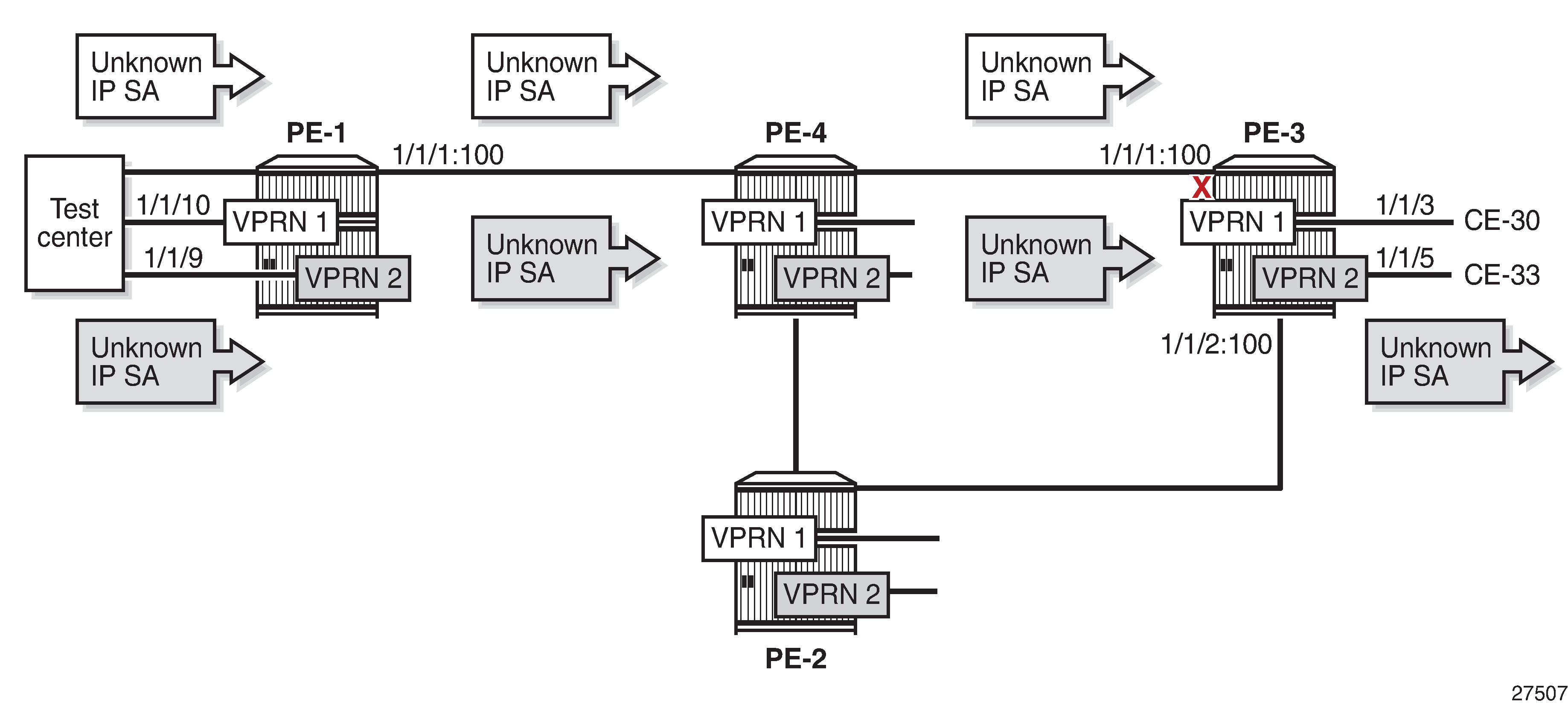
Example Topology in AS 64496 shows the example topology with four routers and a test center. On each of the routers, VPRN 1 and VPRN 2 are configured. The test center, connected to PE-1, can send IPv4 or IPv6 traffic toward the base router (port 1/1/7) and both VPRNs (port 1/1/10 for VPRN 1 and port 1/1/9 for VPRN 2).
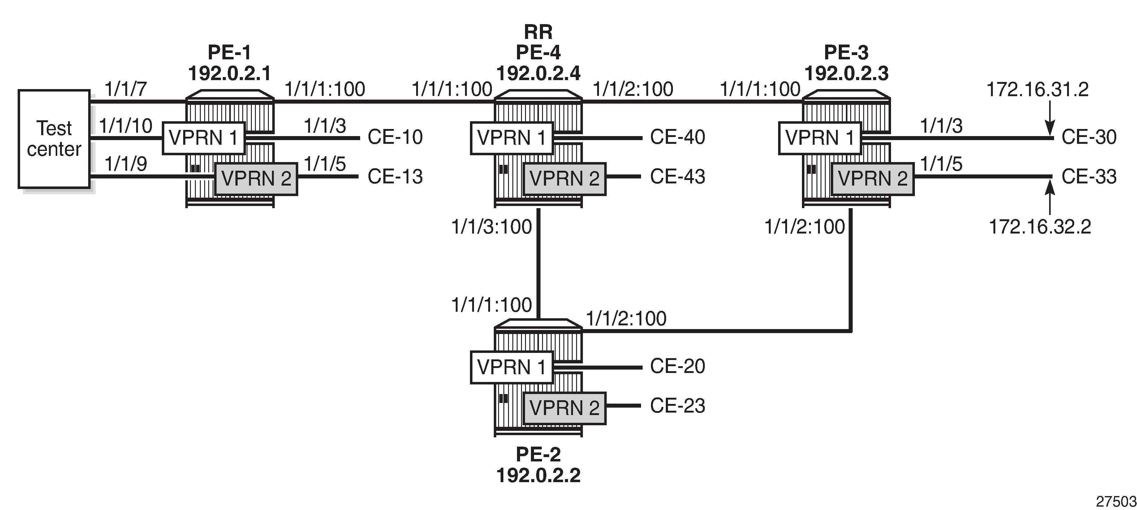
The initial configuration on the four PEs includes the following:
Cards, MDAs
Ports:
Network ports between the PEs and access ports toward the VPRNs on each PE
Port 1/1/7 on PE-1 toward the test center is configured as a network port and is associated with a network interface in the base router. Ports 1/1/9 and 1/1/10 on PE-1 toward the test center are configured as access ports and associated with SAPs in the VPRNs.
Network interfaces between the PEs and from PE-1 to the test center with a dual-stack IPv4/IPv6
IS-IS as IGP (alternatively, OSPF can be used) on all network interfaces
LDP on all network interfaces between the PEs
As an example, the initial configuration on PE-1 is as follows. By default, uRPF is disabled on the network interfaces. The configuration on the other PEs is similar.
*A:PE-1# configure
    router
        interface "int-PE-1-PE-4"
            address 192.168.14.1/30
            port 1/1/1:100
            ipv6
                address 2001:db8::14:1/126
            exit
        exit
        interface "int-PE-1-TestCenter"
            address 192.168.11.1/30
            port 1/1/7
            ipv6
                address 2001:db8::11:1/126
            exit
        exit
        interface "system"
            address 192.0.2.1/32
            ipv6
                address 2001:db8::2:1/128
            exit
        exit
        isis
            area-id 49.0001
            ipv6-routing native
            interface "system"
            exit
            interface "int-PE-1-PE-4"
                interface-type point-to-point
            exit
            no shutdown
        exit
        ldp
            interface-parameters
                interface "int-PE-1-PE-4" dual-stack
                    ipv4
                        no shutdown
                    exit
                exit
            exit
        exit
The initial VPRN service configuration on PE-1 is as follows. Auto-bind-tunnel is enabled and LDP tunnels will be used. The service configuration on the other PEs is similar, excluding the interface to the test center.
configure
    service
        vprn 1 customer 1 create
            description "PE-1-VPRN-1"
            route-distinguisher 64496:1
            auto-bind-tunnel
                resolution any
            exit
            vrf-target target:64496:1
            interface "int-PE-1-CE-10" create
                address 172.16.11.1/24
                ipv6
                    address 2001:db8::11:1/120
                exit
                sap 1/1/3 create
                exit
            exit
            interface "toTestCenter" create
                address 172.16.110.1/24
                ipv6
                    address 2001:db8::110:1/120
                exit
                sap 1/1/10 create
                exit
            exit
            no shutdown
        exit
        vprn 2 customer 1 create
            description "PE-1-VPRN-2"
            route-distinguisher 64496:2
            auto-bind-tunnel
                resolution any
            exit
            vrf-target target:64496:2
            interface "int-PE-1-CE-13" create
                address 172.16.12.1/24
                ipv6
                    address 2001:db8::12:1/120
                exit
                sap 1/1/5 create
                exit
            exit
            interface "toTestCenter" create
                address 172.16.120.1/24
                ipv6
                    address 2001:db8::120:1/120
                exit
                sap 1/1/9 create
                exit
            exit
            no shutdown
        exit
BGP is configured for the VPN-IPv4 and VPN-IPv6 address families with PE-4 as route reflector. The following is the BGP configuration on PE-1:
configure
    router
        autonomous-system 64496
        bgp
            split-horizon
            group "iBGP"
                family vpn-ipv4 vpn-ipv6
                peer-as 64496
                neighbor 192.0.2.4
                exit
            exit
        exit
In this example, no uRPF checking will be enabled on the access interfaces of the VPRNs, but obviously, it might be combined with uRPF control on network interfaces.
The following commands to enable uRPF in strict mode (default) on the access interface are only shown for completeness:
*A:PE-1# configure service vprn 1 interface "toTestCenter" urpf-check
*A:PE-1# configure service vprn 1 interface "toTestCenter" ipv6 urpf-check
With this configuration, packets with spoofed or unknown IP SAs arriving on a VPRN SAP, where uRPF checking is enabled in strict mode, are dropped at the access interface, as shown in uRPF Enabled in Strict Mode on Access Interface in VPRN 1. IP SA 172.16.21.1 has a non-default route in the FIB via a tunnel to PE-2, but packets with this IP SA are not expected on the access interface, so they are dropped in strict mode on interface "toTestCenter" (whereas they would be forwarded in loose mode). All packets with unknown IP SAs—for which there is no non-default route in the FIB of the VPRN—are dropped in strict and in loose mode on interface "toTestCenter".
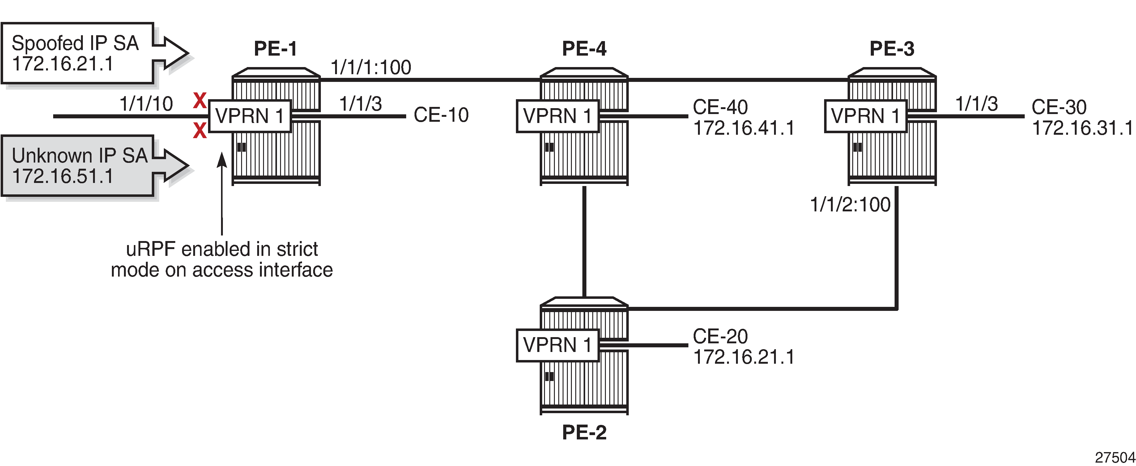
In the remainder of this chapter, uRPF is disabled on the access interfaces, so all packets with spoofed or unknown IP SAs in VPRN 1 will be forwarded by PE-1.
uRPF is enabled on the network interfaces of all PEs. The following commands enable uRPF (in strict mode, by default) for IPv4 and IPv6 on the network interfaces on PE-1. The configuration is similar on the other PEs.
*A:PE-1# configure router interface "int-PE-1-PE-4" urpf-check
*A:PE-1# configure router interface "int-PE-1-PE-4" ipv6 urpf-check
*A:PE-1# configure router interface "int-PE-1-TestCenter" urpf-check
*A:PE-1# configure router interface "int-PE-1-TestCenter" ipv6 urpf-check
The FIB for the base router on PE-1 is as follows.
*A:PE-1# show router fib 1

===============================================================================
FIB Display
===============================================================================
Prefix [Flags]                                              Protocol
  NextHop
-------------------------------------------------------------------------------
192.0.2.1/32                                                LOCAL
  192.0.2.1 (system)
192.0.2.2/32                                                ISIS
  192.168.14.2 (int-PE-1-PE-4)
192.0.2.3/32                                                ISIS
  192.168.14.2 (int-PE-1-PE-4)
192.0.2.4/32                                                ISIS
  192.168.14.2 (int-PE-1-PE-4)
192.168.11.0/30                                             LOCAL
  192.168.11.0 (int-PE-1-TestCenter)
192.168.14.0/30                                             LOCAL
  192.168.14.0 (int-PE-1-PE-4)
192.168.23.0/30                                             ISIS
  192.168.14.2 (int-PE-1-PE-4)
192.168.24.0/30                                             ISIS
  192.168.14.2 (int-PE-1-PE-4)
192.168.34.0/30                                             ISIS
  192.168.14.2 (int-PE-1-PE-4)
-------------------------------------------------------------------------------
Total Entries : 9
The test center sends two traffic flows with IP destination address (DA) 192.0.2.3 to the base router on PE-1. The first traffic flow has IP SA 192.0.2.2, which is the system address of PE-2 and is expected on another network interface, so it will be dropped by uRPF in strict mode. The second traffic flow has IP SA 192.0.2.5 for which there is no non-default route available in the FIB, so it will be dropped due to uRPF checking. uRPF Checking in Strict Mode in Base Router on PE-1 shows how uRPF drops packets with spoofed or unknown IP SAs at the incoming network interface "int-PE-1-TestCenter" on PE-1.
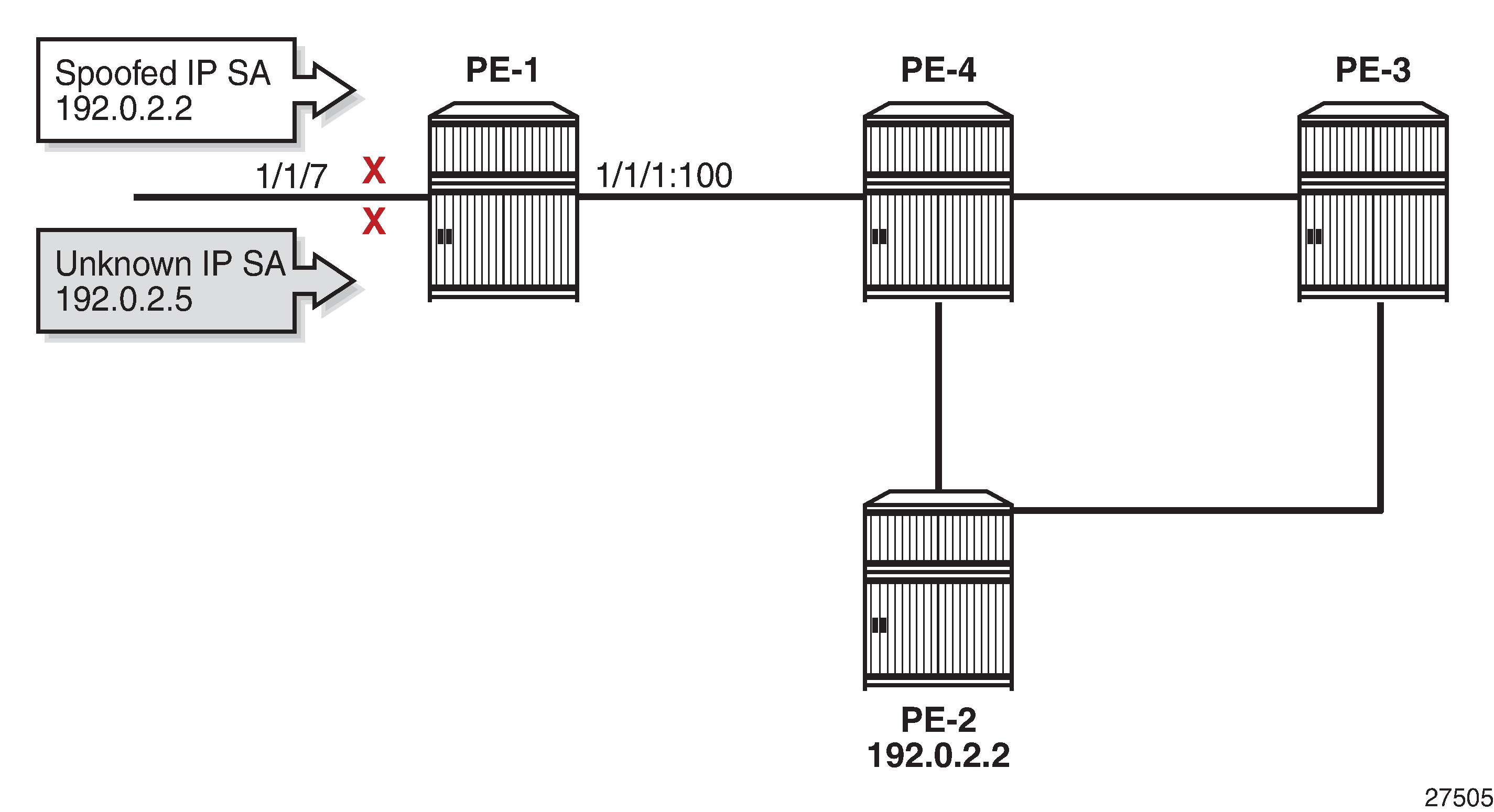
The following monitor command output on PE-1 shows that the incoming traffic on network port 1/1/7 toward the test center is dropped. No traffic is forwarded to port 1/1/1 toward PE-4. The packets sent and received on port 1/1/1 are of a different nature, such as IS-IS messages.
*A:PE-1# monitor port 1/1/1 1/1/7 rate interval 3 repeat 2

===============================================================================
Monitor statistics for Ports
===============================================================================
                                                   Input                 Output
-------------------------------------------------------------------------------
---snip---
-------------------------------------------------------------------------------
At time t = 3 sec (Mode: Rate)
-------------------------------------------------------------------------------
Port 1/1/1
-------------------------------------------------------------------------------
Octets                                               214                    140
Packets                                                2                      2
Errors                                                 0                      0
Bits                                                1712                   1120
Utilization (% of port capacity)                   ~0.00                  ~0.00

Port 1/1/7
-------------------------------------------------------------------------------
Octets                                            270251                      0
Packets                                             2111                      0
Errors                                                 0                      0
Bits                                             2162008                      0
Utilization (% of port capacity)                    2.49                   0.00

-------------------------------------------------------------------------------
---snip---
The IPv6 FIB on PE-1 is as follows.
*A:PE-1# show router fib 1 ipv6

===============================================================================
FIB Display
===============================================================================
Prefix [Flags]                                              Protocol
  NextHop
-------------------------------------------------------------------------------
2001:db8::2:1/128                                           LOCAL
  2001:db8::2:1 (system)
2001:db8::2:2/128                                           ISIS
  fe80::628:1ff:fe01:1 (int-PE-1-PE-4)
2001:db8::2:3/128                                           ISIS
  fe80::628:1ff:fe01:1 (int-PE-1-PE-4)
2001:db8::2:4/128                                           ISIS
  fe80::628:1ff:fe01:1 (int-PE-1-PE-4)
2001:db8::11:0/126                                          LOCAL
  2001:db8::11:0 (int-PE-1-TestCenter)
2001:db8::14:0/126                                          LOCAL
  2001:db8::14:0 (int-PE-1-PE-4)
2001:db8::23:0/126                                          ISIS
  fe80::628:1ff:fe01:1 (int-PE-1-PE-4)
2001:db8::24:0/126                                          ISIS
  fe80::628:1ff:fe01:1 (int-PE-1-PE-4)
2001:db8::34:0/126                                          ISIS
  fe80::628:1ff:fe01:1 (int-PE-1-PE-4)
-------------------------------------------------------------------------------
Total Entries : 9
Similar results occur for IPv6 traffic with IP DA 2001:db8::2:3 and IP SA 2001:db8::2:2 (system IPv6 address of PE-2) or IP SA 2001:db8::2:5 (unknown IP SA). The following port statistics show that the packets are dropped at the incoming port 1/1/7 toward the test center instead of being forwarded to port 1/1/1 toward PE-4. Instead of using the port statistics, the preceding monitor command can also be used.
*A:PE-1# clear port 1/1/[1..10] statistics
*A:PE-1# sleep 2
*A:PE-1# show port 1/1/[1..10] statistics

===============================================================================
Port Statistics on Slot 1
===============================================================================
Port                    Ingress         Ingress         Egress           Egress
Id                      Packets          Octets         Packets          Octets
-------------------------------------------------------------------------------
1/1/1                         3             426               2             253
===============================================================================

===============================================================================
Port Statistics on Slot 1
===============================================================================
Port                    Ingress         Ingress         Egress           Egress
Id                      Packets          Octets         Packets          Octets
-------------------------------------------------------------------------------
1/1/7                      4236          542208               0               0
===============================================================================
*A:PE-1#
uRPF Control on Network Interfaces Inherited by VPRNs
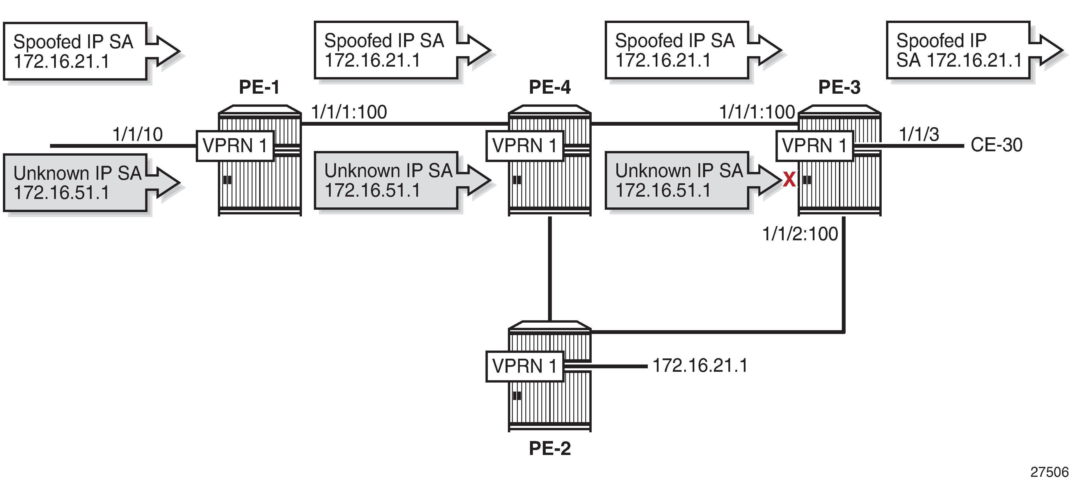
By default, the uRPF control settings of the network interface are inherited by the VPRNs.
The test center sends a first traffic flow with IP DA 172.16.31.2 (CE-30) to SAP 1/1/10 of VPRN 1 on PE-1. The traffic flow has IP SA 172.16.21.1, which has a non-default route in the FIB of VPRN 1 on all PEs. Afterward, the test center sends a second traffic flow with IP DA 172.16.31.2 (CE-30) to SAP 1/1/10 of VPRN 1 on PE-1. These packets have IP SA 172.16.51.1, which is unknown in the VPRN FIB. uRPF is disabled on the access interface, so the packets are not dropped at the SAP, but forwarded in tunnels toward PE-3. No uRPF checking is performed on PE-4, because it is not the endpoint of the tunnel. The tunnel terminates at PE-3 and uRPF is checked on the incoming network interface. The FIB for VPRN 1 on PE-3 is as follows.
*A:PE-3# show router 1 fib 1

===============================================================================
FIB Display
===============================================================================
Prefix [Flags]                                              Protocol
  NextHop
-------------------------------------------------------------------------------
172.16.11.0/24                                              BGP_VPN
  192.0.2.1 (VPRN Label:262135 Transport:LDP)
172.16.21.0/24                                              BGP_VPN
  192.0.2.2 (VPRN Label:262135 Transport:LDP)
172.16.31.0/24                                              LOCAL
  172.16.31.0 (int-CE-31-CE-30)
172.16.41.0/24                                              BGP_VPN
  192.0.2.4 (VPRN Label:262135 Transport:LDP)
172.16.110.0/24                                             BGP_VPN
  192.0.2.1 (VPRN Label:262135 Transport:LDP)
-------------------------------------------------------------------------------
Total Entries : 5
All IP packets with IP SA 172.16.21.1 will be forwarded to CE-30, regardless of the interface where they are received, because no network interface is associated with prefix 172.16.21.0/24 in the FIB of VPRN 1. uRPF Checking in VPRN 1 on PE-3 shows that the only packets that will be dropped on PE-3 have an IP SA for which no non-default route is present in the FIB of VPRN 1; in this case, IP SA 172.16.51.1.
The following monitor command output on PE-3 for the traffic flow with IP DA 172.16.31.2 and IP SA 172.16.21.1 shows that the traffic is forwarded to port 1/1/3 toward CE-30.
*A:PE-3# monitor port 1/1/1 1/1/3 rate interval 3 repeat 2

===============================================================================
Monitor statistics for Ports
===============================================================================
                                                   Input                 Output
-------------------------------------------------------------------------------
---snip---
-------------------------------------------------------------------------------
At time t = 3 sec (Mode: Rate)
-------------------------------------------------------------------------------
Port 1/1/1
-------------------------------------------------------------------------------
Octets                                            295703                    174
Packets                                             2112                      1
---snip---

Port 1/1/3
-------------------------------------------------------------------------------
Octets                                                 0                 270251
Packets                                                0                   2111
---snip---
The following monitor command output on PE-3 for the traffic flow with IP DA 172.16.31.2 and unknown IP SA 172.16.51.1 shows that the traffic is dropped at ingress port 1/1/1 instead of being forwarded to port 1/1/3 toward CE-30.
*A:PE-3# monitor port 1/1/1 1/1/3 rate interval 3 repeat 2

===============================================================================
Monitor statistics for Ports
===============================================================================
                                                   Input                 Output
-------------------------------------------------------------------------------
---snip---
-------------------------------------------------------------------------------
At time t = 3 sec (Mode: Rate)
-------------------------------------------------------------------------------
Port 1/1/1
-------------------------------------------------------------------------------
Octets                                            295630                    154
Packets                                             2112                      1
---snip---

Port 1/1/3
-------------------------------------------------------------------------------
Octets                                                 0                      0
Packets                                                0                      0
---snip---
Similar results occur for IPv6 traffic flows toward CE-30 with spoofed or unknown IP SAs, but they are not included here. The IPv6 FIB for VPRN 1 on PE-3 is as follows.
*A:PE-3# show router 1 fib 1 ipv6

===============================================================================
FIB Display
===============================================================================
Prefix [Flags]                                              Protocol
  NextHop
-------------------------------------------------------------------------------
2001:db8::11:0/120                                          BGP_VPN
  192.0.2.1 (VPRN Label:262135 Transport:LDP)
2001:db8::21:0/120                                          BGP_VPN
  192.0.2.2 (VPRN Label:262135 Transport:LDP)
2001:db8::31:0/120                                          LOCAL
  2001:db8::31:0 (int-CE-31-CE-30)
2001:db8::41:0/120                                          BGP_VPN
  192.0.2.4 (VPRN Label:262135 Transport:LDP)
2001:db8::110:0/120                                         BGP_VPN
  192.0.2.1 (VPRN Label:262135 Transport:LDP)
-------------------------------------------------------------------------------
Total Entries : 5
To show selective uRPF for different VPRNs, uRPF checking is needed on the network interfaces for VPRN 1, but not for VPRN 2. To achieve this, additional configuration is required to exclude VPRN 2 from the uRPF check. The following configuration in VPRN 2 is required, but not sufficient to exclude VPRN 2 from the uRPF check.
*A:PE-3# configure service vprn 2 network ingress no urpf-check
This setting is ignored because no selective VPRN uRPF checking is enabled on the network-interfaces level and the behavior remains unchanged: the uRPF settings are inherited by VPRN 2, even though the configuration in VPRN 2 might be misleading. When the test center generates a traffic flow with IP DA 172.16.32.2 (CE-33) and unknown IP SA 172.16.52.1, the traffic is dropped by PE-3 after uRPF checking. The FIB for VPRN 2 on PE-3 is as follows.
*A:PE-3# show router 2 fib 1

===============================================================================
FIB Display
===============================================================================
Prefix [Flags]                                              Protocol
  NextHop
-------------------------------------------------------------------------------
172.16.12.0/24                                              BGP_VPN
  192.0.2.1 (VPRN Label:262134 Transport:LDP)
172.16.22.0/24                                              BGP_VPN
  192.0.2.2 (VPRN Label:262134 Transport:LDP)
172.16.32.0/24                                              LOCAL
  172.16.32.0 (int-CE-32-CE-33)
172.16.42.0/24                                              BGP_VPN
  192.0.2.4 (VPRN Label:262134 Transport:LDP)
172.16.120.0/24                                             BGP_VPN
  192.0.2.1 (VPRN Label:262134 Transport:LDP)
-------------------------------------------------------------------------------
Total Entries : 5
The following monitor command output on PE-3 shows that the traffic that enters network port 1/1/1 with unknown IP address is dropped; no packets are forwarded to port 1/1/5 toward CE-33. This implies that uRPF control is still active for VPRN 2.
*A:PE-3# monitor port 1/1/1 1/1/5 rate interval 3 repeat 2

===============================================================================
Monitor statistics for Ports
===============================================================================
                                                   Input                 Output
-------------------------------------------------------------------------------
---snip---

-------------------------------------------------------------------------------
At time t = 3 sec (Mode: Rate)
-------------------------------------------------------------------------------
Port 1/1/1
-------------------------------------------------------------------------------
Octets                                            295869                    227
Packets                                             2114                      2
---snip---

Port 1/1/5
-------------------------------------------------------------------------------
Octets                                                 0                      0
Packets                                                0                      0
---snip---
A similar result occurs for IPv6 traffic toward CE-33 with IP DA 2001:db8::32:2 and unknown IP SA 2001:db8::52:1. The IPv6 FIB for VPRN 2 on PE-3 is as follows.
*A:PE-3# show router 2 fib 1 ipv6

===============================================================================
FIB Display
===============================================================================
Prefix [Flags]                                              Protocol
  NextHop
-------------------------------------------------------------------------------
2001:db8::12:0/120                                          BGP_VPN
  192.0.2.1 (VPRN Label:262134 Transport:LDP)
2001:db8::22:0/120                                          BGP_VPN
  192.0.2.2 (VPRN Label:262134 Transport:LDP)
2001:db8::32:0/120                                          LOCAL
  2001:db8::32:0 (int-CE-32-CE-33)
2001:db8::42:0/120                                          BGP_VPN
  192.0.2.4 (VPRN Label:262134 Transport:LDP)
2001:db8::120:0/120                                         BGP_VPN
  192.0.2.1 (VPRN Label:262134 Transport:LDP)
-------------------------------------------------------------------------------
Total Entries : 5
Selective VPRN uRPF Control on Network Interfaces
Selective VPRN uRPF control on network interfaces requires the following:
uRPF configured on the network interfaces (by default disabled): urpf-check
Selective VPRN uRPF control enabled on the network interfaces: urpf-selected-vprns (by default disabled)
[no] urpf-check configured on the network ingress of the VPRNs (by default enabled)
In this example, uRPF is already configured on the network interfaces. The configuration on PE-3 is as follows.
*A:PE-3# configure router interface "int-PE-3-PE-2" urpf-check
*A:PE-3# configure router interface "int-PE-3-PE-2" ipv6 urpf-check
*A:PE-3# configure router interface "int-PE-3-PE-4" urpf-check
*A:PE-3# configure router interface "int-PE-3-PE-4" ipv6 urpf-check
Selective VPRN uRPF control needs to be enabled on all nodes. The configuration on PE-3 is as follows.
*A:PE-3# configure router interface "int-PE-3-PE-2" urpf-selected-vprns
*A:PE-3# configure router interface "int-PE-3-PE-4" urpf-selected-vprns
uRPF checking is enabled for VPRN 1 (default) and disabled for VPRN 2, as follows.
*A:PE-3# configure service vprn 2 network ingress no urpf-check
When the test center generates a traffic flow with IP DA 172.16.31.2 (CE-30) and unknown IP SA 172.16.51.1 in VPRN 1, the packets will be dropped at the incoming network port 1/1/1 on PE-3. For VPRN 2, traffic with IP DA 172.16.32.2 (CE-33) is forwarded, even if the IP SA is unknown (such as 172.16.52.1), because uRPF checking is disabled. Selective VPRN uRPF on Network Interfaces Enabled for VPRN 1 and Disabled for VPRN 2 shows that packets with unknown IP SA in VPRN 1 are dropped by uRPF control on PE-3, while packets with unknown IP SA in VPRN 2 are forwarded on PE-3.
The following monitor command output shows that traffic in VPRN 1 with IP DA 172.16.31.2 and IP SA 172.16.51.1 is dropped at incoming port 1/1/1 on PE-3. A similar result occurs for IPv6 addressing.
*A:PE-3# monitor port 1/1/1 1/1/3 rate interval 3 repeat 2

===============================================================================
Monitor statistics for Ports
===============================================================================
                                                   Input                 Output
-------------------------------------------------------------------------------
---snip---
-------------------------------------------------------------------------------
At time t = 3 sec (Mode: Rate)
-------------------------------------------------------------------------------
Port 1/1/1
-------------------------------------------------------------------------------
Octets                                            295667                    163
Packets                                             2112                      1
---snip---

Port 1/1/3
-------------------------------------------------------------------------------
Octets                                                 0                      0
Packets                                                0                      0
---snip---
The following monitor command output shows that traffic in VPRN 2 with IP DA 172.16.32.2 and IP SA 172.16.52.1 is forwarded to port 1/1/5 on PE-3 toward CE-33. A similar result occurs for IPv6 addressing.
*A:PE-3# monitor port 1/1/1 1/1/3 1/1/5 1/1/9 rate interval 3 repeat 2

===============================================================================
Monitor statistics for Ports
===============================================================================
                                                   Input                 Output
-------------------------------------------------------------------------------
---snip---
-------------------------------------------------------------------------------
At time t = 3 sec (Mode: Rate)
-------------------------------------------------------------------------------
Port 1/1/1
-------------------------------------------------------------------------------
Octets                                            293565                    186
Packets                                             2097                      1
---snip---

Port 1/1/5
-------------------------------------------------------------------------------
Octets                                                 0                 268160
Packets                                                0                   2095
---snip---
The uRPF control in the base router remains unchanged. In strict mode, PE-1 will drop all packets with spoofed or unknown IP addresses on the incoming network interface, as shown in uRPF Checking in Strict Mode in Base Router on PE-1.
Conclusion
uRPF checking can help service providers to mitigate spoofing attacks. uRPF checking can be executed for all base router traffic and VPRN traffic independently. When the routes held by specific VPRNs are asymmetric, it may be useful to exclude those VPRNs from network ingress uRPF checking.