NG-MVPN Inter-AS Model B Using Non-Segmented mLDP Tunnels
This chapter provides information about NG-MVPN Inter-AS Model B Using Non-Segmented mLDP Tunnels.
Topics in this chapter include:
Applicability
The information and configuration in this chapter are based on SR OS Release 23.10.R2.
There is no specific configuration required to support non-segmented mLDP for inter-AS model B. However, VPN-recursive mLDP Forwarding Equivalence Class (FEC) functionality must be supported.
The configuration of multicast in a VPRN is described in the chapter NG-MVPN Configuration with MPLS.
Overview
Multicast in an inter-AS model B network using Draft-Rosen techniques is described in the chapter Rosen MVPN Inter-AS Option B, where the set of Multicast Distribution Trees (MDTs) are signaled using Protocol Independent Multicast Source-Specific Mode (PIM-SSM).
It is also possible to create MDTs between PEs in different Autonomous Systems (ASs) for Next-Generation MVPN (NG-MVPN) using non-segmented dynamic multicast LDP (mLDP) trees, where the root and leaf PEs are in different ASs. This chapter describes the configuration of MVPN services between PEs in different ASs using NG-MVPN techniques.
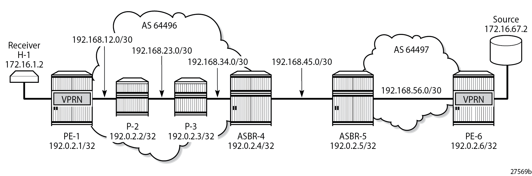
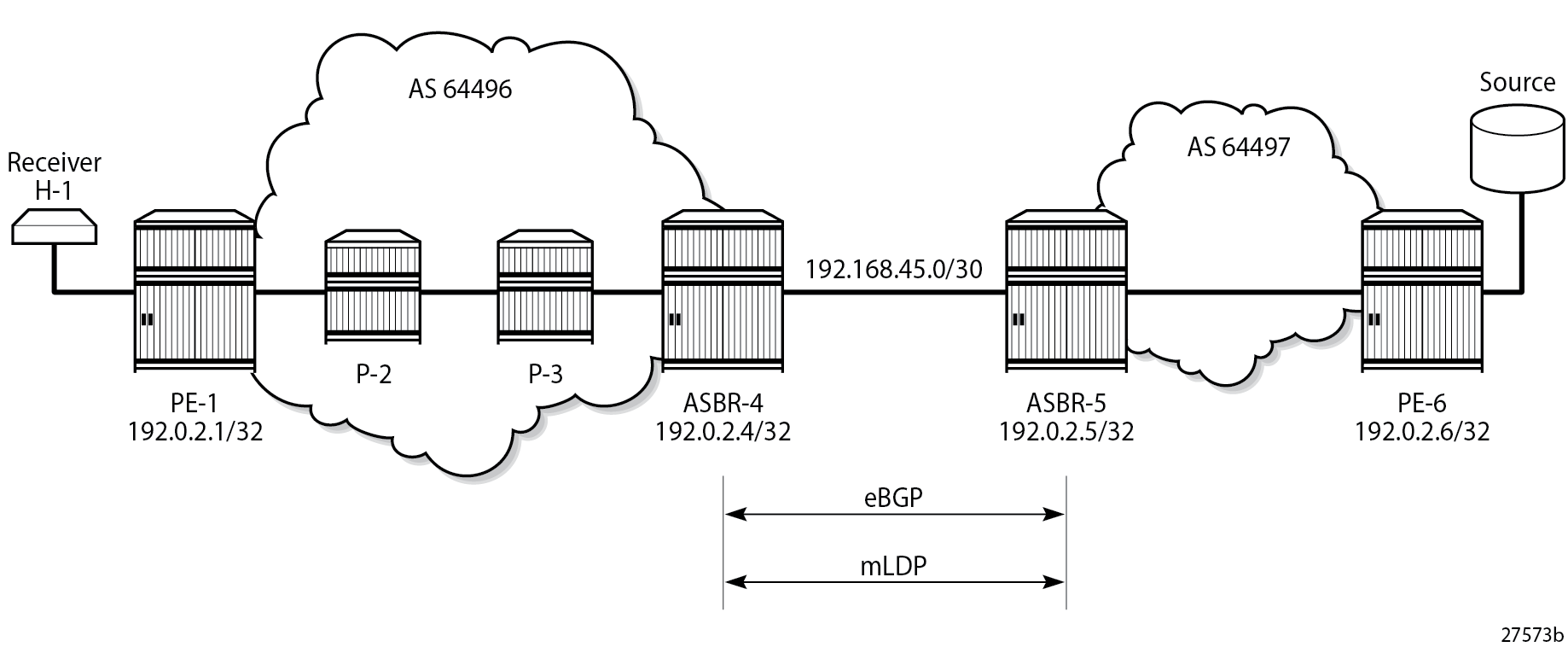
NG-MVPN Inter-AS Model B shows an example of a network comprising routers in two neighboring ASs, modeled as an inter-AS model B network.
A VPRN instance exists on PE-1 and PE-6, with a single source and receiver. PE-1 is connected to its local Autonomous System Border Router (ASBR) via a pair of core routers, P-2 and P-3, neither of which are members of the VPRN instance. P-2 acts as a Route Reflector (RR) for AS 64496.
The source router generates multicast traffic with a group address of 239.255.0.1, and the receiver H-1 in AS 64496 becomes a member of the multicast group using IGMPv3 signaling.
No multicast protocols are configured on the ASBRs.
In an MVPN, a transport tunnel is signaled that carries multicast traffic from source PE to any receiver PE that contains attached multicast routers, or hosts that want to become multicast group members. In this case, a multicast LDP (mLDP) tunnel is signaled between source PE and destination PEs to carry multicast traffic across the multi-AS provider network.
The mLDP Provider Multicast Service Interface (PMSI), also known as the provider tunnel, is established between PEs that declare membership of the MVPN, by generating and advertising an MVPN type 1 intra-AD BGP route. This route contains a PMSI Tunnel Attribute (PTA) that describes the tunnel type, the root node, and the LSP ID. Upon receipt of the intra-AD route, the receiving PE checks that the route is valid and can be imported into the VPRN instance. If the route is valid, the receiving router signals a point-to-multipoint (P2MP) LDP label mapping message toward the root address contained within the PTA of the intra-AD route. At the root, MPLS-encapsulated multicast traffic is forwarded to the downstream router by pushing on a label received from the downstream router.
Inter-AS model B unicast has VPN-IPv4 routes advertised from one AS to the other across the AS boundary. No system addresses of the PEs within an AS are advertised across the AS boundary, so the path for inter-AS unicast traffic is resolved using the labeled VPN-IPv4 routes via the ASBR, using MPLS encapsulation. In a unicast environment, traffic from PE-1 to PE-6 would be encapsulated in a tunnel to ASBR-4, de-encapsulated at ASBR-4, forwarded to ASBR-5, and on toward PE-6. The tunnel comprises the MPLS transport label plus the label associated with the VPN-IPv4 route.
For unicast routes, BGP next-hop-self is performed on the ASBR (from a control plane perspective) while service labels are swapped at the ASBR within the data plane side. This results in a segmented approach.
Multicast traffic requires a non-segmented provider tunnel to be routed from the root PE toward the receiver routers. This means that the tunnel must traverse the AS boundary without de-encapsulation, and therefore, must be non-segmented.
If the provider tunnel uses mLDP, the receivers initiate the signaling by sending an LDP label mapping message along the control path toward the root. This follows the path of the intra-AD route that advertises the root of the I-PMSI. An mLDP label mapping message consists of an allocated label L, with FEC element <X,Y>, where X identifies the root node and Y is the opaque value, so the P2MP label mapping can be denoted as <X,Y,L>.
The FEC element contains the root address of the LSP plus a variable length opaque value. The opaque value contains information meaningful to the root and leaf routers, but not to intermediate routers; for example, a P2MP LSP-ID or a nested opaque value.
The root address is the system address of the router that advertised the intra-AD route. PE-1 has no unicast route to PE-6, but has learned the ASBR-4 address from the BGP next-hop of the intra-AD MVPN route.
However, in an mLDP environment, each router must take part in the signaling of the P2MP LSP, but not every router has an MVPN route, so any mLDP label mapping message received by P-3 to the root address of PE-6 is dropped.
A solution to this is described in RFC 6512, Using Multipoint LDP When the Backbone Has No Route to the Root.
PE-1 signals an mLDP LSP as if the root is at ASBR-4. P-2 and P-3 have a route to ASBR-4 as they are part of the same IGP instance. The actual root address on PE-6 is encapsulated within the mLDP label mapping message originated by PE-1 as an inner root address. This is a recursive FEC type, where the actual root FEC element is encapsulated within a FEC element as an opaque value that has a root at the ASBR.
ASBR-4 does not have a unicast route toward PE-6, but it has received the intra-AD MVPN route advertised by PE-6. This intra-AD route contains the BGP next-hop of ASBR-5, so a path toward PE-6 exists if the address in this route is used. To distinguish between any number of intra-AD routes at the ASBR, the recursive FEC contains the intra-AD route-distinguisher (RD) as an opaque value, which is used with the root address to match the correct intra-AD route.
This recursive FEC is defined as a VPN-recursive FEC, because the VPN intra-AD route is used as the route lookup to forward the label mapping message.
mLDP Message Opaque Value Types in MVPN Model B shows the opaque value types used in MVPN model B.
Opaque Type |
Opaque Name |
Use |
FEC Element Representation |
|---|---|---|---|
1 |
Generic |
VPRN local AS |
Root, Opaque<P2MP ID> |
8 |
VPN Recursive |
Inter-AS model B mLDP |
<ASBR, Opaque <RD, Root, P2MP ID>> |
Configuration
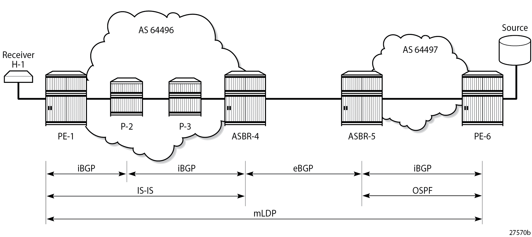
Inter-AS MVPN Protocol Requirements shows the required protocol configuration and peering.
AS 64496
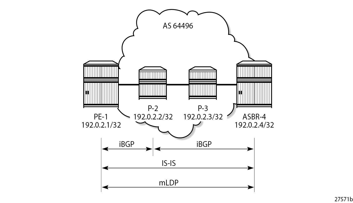
AS 64496 Protocols shows the protocol requirements for AS 64496.
Router Interface and IS-IS Configuration
The first step is to configure the router interfaces and IS-IS as the Interior Gateway Protocol (IGP) in AS 64496.
The router interfaces for PE-1 are configured as follows:
# on PE-1:
configure
    router
        interface "int-PE-1-P-2"
            address 192.168.12.1/30
            port 1/1/c1/1
        exit
        interface "system"
            address 192.0.2.1/32
        exit
Each interface is configured to run IS-IS as the IGP. Each router is configured as a level 2 router.
# on PE-1:
configure
    router
        isis 0
            level-capability level-2
            area-id 49.0001
            traffic-engineering
            level 2
                wide-metrics-only
            exit
            interface "system"
                level-capability level-2
            exit
            interface "int-PE-1-P-2"
                level-capability level-2
                interface-type point-to-point
            exit
            no shutdown
        exit
The configuration for all other nodes in the AS is the same, apart from the IP addresses. The IP addresses can be derived from NG-MVPN Inter-AS Model B.
LDP Configuration
Label Distribution Protocol (LDP) is used as the MPLS protocol and must be enabled on each router interface, as follows:
# on PE-1:
configure
    router
        ldp
            import-pmsi-routes
                mvpn    # needed for bindings
            exit
            tcp-session-parameters
            exit
            interface-parameters
                interface "int-PE-1-P-2" dual-stack
                    ipv4
                        fec-type-capability
                            p2mp-ipv4 enable        # default
                        exit
                    exit
                exit
            exit
            targeted-session
            exit
        exit
This configuration must be repeated on each of the other routers in the AS. As LDP is used as the provider tunnel interface for multicast traffic, each interface must also support P2MP LDP tunnels. Therefore, the FEC type capability for IPv4 P2MP tunnels must be enabled. The default value is enable, but is included in the preceding configuration for clarity.
BGP Configuration
P-2 Route Reflector
P-2 is configured as an RR within AS 64496 and peers with both PE-1 and PE-4. The address families negotiated are VPN-IPv4 for unicast VPRN routes, and MVPN-IPv4 routes for multicast VPRN routes. The cluster ID is set to ensure that P-2 is an RR.
# on P-2:
configure
    router
        autonomous-system 64496
        bgp
            cluster 192.0.2.2
            group "internal"
                family vpn-ipv4 mvpn-ipv4
                type internal
                cluster 192.0.2.2
                neighbor 192.0.2.1
                exit
                neighbor 192.0.2.4
                exit
            exit
            no shutdown
        exit
PE-1
PE-1 is a BGP peer of RR P-2, as follows:
# on PE-1:
configure
    router
        autonomous-system 64496
        bgp
            group "internal"
                family vpn-ipv4 mvpn-ipv4
                type internal
                neighbor 192.0.2.2
                exit
            exit
            no shutdown
        exit
ASBR-4
For completeness, the ASBR-4 BGP configuration is as follows.
# on ASBR-4:
configure
    router
        autonomous-system 64496
        bgp
            family vpn-ipv4 mvpn-ipv4
            group "internal"
                type internal
                neighbor 192.0.2.2
                exit
            exit
            no shutdown
        exit
AS 64497
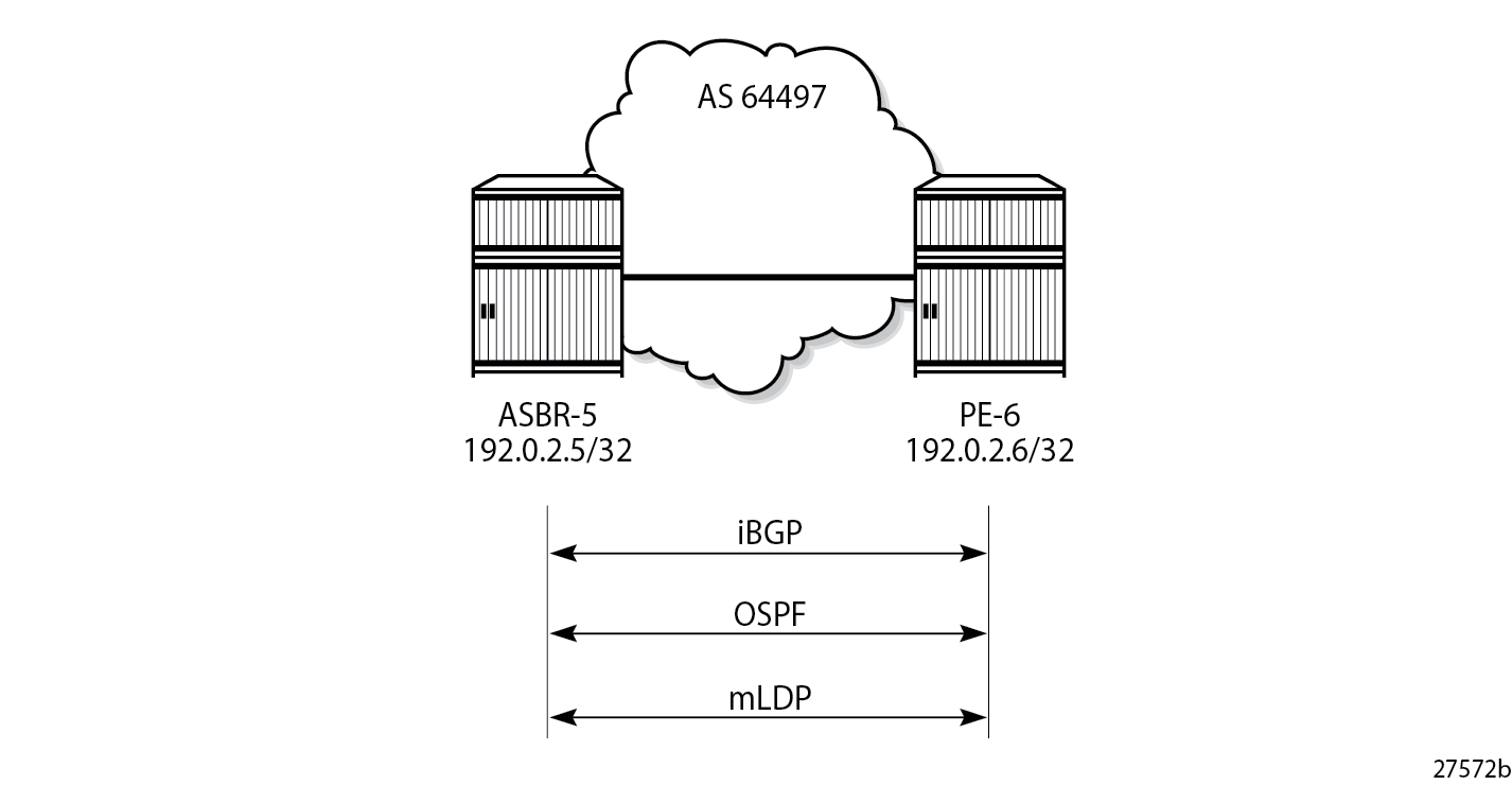
AS 64497 Protocols shows the protocol requirements for AS 64497.
Router Interface and OSPF Configuration
The first step is to configure router interfaces and OSPF on each router shown in AS 64497 Protocols. All router interfaces are members of a single backbone area: area 0.0.0.0.
The following router interfaces are configured on PE-6:
# on PE-6:
configure
    router
        interface "int-PE-6-ASBR-5"
            address 192.168.56.2/30
            port 1/1/c2/1
        exit
        interface "system"
            address 192.0.2.6/32
        exit
The configuration for PE-6 to enable OSPF is:
# on PE-6:
configure
    router
        ospf 0
            area 0.0.0.0
                interface "int-PE-6-ASBR-5"
                    interface-type point-to-point
                exit
                interface "system"
                    interface-type point-to-point
                exit
            exit
            no shutdown
        exit
LDP Configuration
LDP is used as the MPLS protocol and must be enabled on each router interface, as follows.
# on PE-6:
configure
    router
        ldp
            import-pmsi-routes
            exit
            tcp-session-parameters
            exit
            interface-parameters
                interface "int-PE-6-ASBR-5" dual-stack
                    ipv4
                        fec-type-capability
                            p2mp-ipv4 enable
                        exit
                    exit
                exit
            exit
            targeted-session
            exit
        exit
This configuration must be repeated on each of the other routers in the AS. Again, the default value of FEC type capability for P2MP is enable, but is included for clarity.
BGP Configuration
Within AS 64497, internal BGP peering is required between ASBR-5 and PE-6 for the VPN-IPv4 and MVPN-IPv4 address families.
The following shows the BGP configuration for such a peering.
# on ASBR-5:
configure
    router
        autonomous-system 64497
        bgp
            family vpn-ipv4 mvpn-ipv4
            group "internal"
                type internal
                neighbor 192.0.2.6
                exit
            exit
            no shutdown
        exit
# on PE-6:
configure
router
autonomous-system 64497
bgp
rapid-withdrawal
rapid-update mvpn-ipv4 vpn-ipv4
group "internal"
family vpn-ipv4 mvpn-ipv4
type internal
neighbor 192.0.2.5
exit
exit
no shutdown
exitInter-AS Configuration
Inter-AS Protocols shows the protocols required between ASBR-4 and ASBR-5. The LDP transport address and the BGP speaker peer addresses are the interface addresses.
eBGP Peering
The following shows the eBGP peering configuration for ASBR-4. The peer address is the interface address of ASBR-5.
# on ASBR-4:
configure
    router
        autonomous-system 64496
        bgp
            family vpn-ipv4 mvpn-ipv4
            enable-inter-as-vpn         # required for inter-AS VPN option B
            split-horizon
            group "external"
                peer-as 64497
                neighbor 192.168.45.2
                exit
            exit
            no shutdown
        exit
Similarly, the BGP configuration for ASBR-5 peering toward ASBR-4 is as follows:
# on ASBR-5:
configure
    router
        autonomous-system 64497
        bgp
            family vpn-ipv4 mvpn-ipv4
            enable-inter-as-vpn         # required for inter-AS VPN option B
            split-horizon
            group "external"
                peer-as 64496
                neighbor 192.168.45.1
                exit
            exit
            no shutdown
        exit
Verification of the BGP peering session between ASBR-4 and ASBR-5 is shown in the following output:
# on ASBR-4:
*A:ASBR-4# show router bgp summary group "external"
===============================================================================
 BGP Router ID:192.0.2.4        AS:64496       Local AS:64496
===============================================================================
BGP Admin State         : Up          BGP Oper State              : Up
Total Peers             : 1

Total IPv4 Remote Rts   : 0           Total IPv4 Rem. Active Rts  : 0
Total IPv6 Remote Rts   : 0           Total IPv6 Rem. Active Rts  : 0
Total IPv4 Backup Rts   : 0           Total IPv6 Backup Rts       : 0
Total LblIpv4 Rem Rts   : 0           Total LblIpv4 Rem. Act Rts  : 0
Total LblIpv6 Rem Rts   : 0           Total LblIpv6 Rem. Act Rts  : 0
Total LblIpv4 Bkp Rts   : 0           Total LblIpv6 Bkp Rts       : 0

Total VPN-IPv4 Rem. Rts : 0           Total VPN-IPv4 Rem. Act. Rts: 0
Total VPN-IPv6 Rem. Rts : 0           Total VPN-IPv6 Rem. Act. Rts: 0
Total VPN-IPv4 Bkup Rts : 0           Total VPN-IPv6 Bkup Rts     : 0

Total MVPN-IPv4 Rem Rts : 0           Total MVPN-IPv4 Rem Act Rts : 0
Total MVPN-IPv6 Rem Rts : 0           Total MVPN-IPv6 Rem Act Rts : 0
Total MDT-SAFI Rem Rts  : 0           Total MDT-SAFI Rem Act Rts  : 0
Total McIPv4 Remote Rts : 0           Total McIPv4 Rem. Active Rts: 0
Total McIPv6 Remote Rts : 0           Total McIPv6 Rem. Active Rts: 0
Total McVpnIPv4 Rem Rts : 0           Total McVpnIPv4 Rem Act Rts : 0
Total McVpnIPv6 Rem Rts : 0           Total McVpnIPv6 Rem Act Rts : 0

Total EVPN Rem Rts      : 0           Total EVPN Rem Act Rts      : 0
Total L2-VPN Rem. Rts   : 0           Total L2VPN Rem. Act. Rts   : 0
Total MSPW Rem Rts      : 0           Total MSPW Rem Act Rts      : 0
Total RouteTgt Rem Rts  : 0           Total RouteTgt Rem Act Rts  : 0
Total FlowIpv4 Rem Rts  : 0           Total FlowIpv4 Rem Act Rts  : 0
Total FlowIpv6 Rem Rts  : 0           Total FlowIpv6 Rem Act Rts  : 0
Total FlowVpnv4 Rem Rts : 0           Total FlowVpnv4 Rem Act Rts : 0
Total FlowVpnv6 Rem Rts : 0           Total FlowVpnv6 Rem Act Rts : 0
Total Link State Rem Rts: 0           Total Link State Rem Act Rts: 0
Total SrPlcyIpv4 Rem Rts: 0           Total SrPlcyIpv4 Rem Act Rts: 0
Total SrPlcyIpv6 Rem Rts: 0           Total SrPlcyIpv6 Rem Act Rts: 0

===============================================================================
BGP Summary
===============================================================================
Legend : D - Dynamic Neighbor
===============================================================================
Neighbor
Description
                   AS PktRcvd InQ  Up/Down   State|Rcv/Act/Sent (Addr Family)
                      PktSent OutQ
-------------------------------------------------------------------------------
192.168.45.2
                64497      10    0 00h03m01s 0/0/0 (VpnIPv4)
                           10    0           0/0/0 (MvpnIPv4)
-------------------------------------------------------------------------------
LDP Peering
LDP is configured as the MPLS protocol between ASBR-4 and ASBR-5. On ASBR-4, the interface toward ASBR-5 has LDP enabled, as follows:
# on ASBR-4:
configure
    router
        ldp
            import-pmsi-routes
                mvpn    # needed for bindings
            exit
            tcp-session-parameters
            exit
            interface-parameters
                interface "int-ASBR-4-ASBR-5" dual-stack
                    ipv4
                        fec-type-capability
                            p2mp-ipv4 enable
                        exit
                        transport-address interface
                    exit
                exit
            exit
            targeted-session
            exit
        exit
The P2MP FEC type capability for P2MP LDP is shown. This is the default value.
For completeness, the LDP configuration on ASBR-5 for the interface toward ASBR-4 is as follows:
# on ASBR-5:
configure
    router
        ldp
            import-pmsi-routes
            exit
            tcp-session-parameters
            exit
            interface-parameters
                interface "int-ASBR-5-ASBR-4" dual-stack
                    ipv4
                        fec-type-capability
                            p2mp-ipv4 enable
                        exit
                        transport-address interface
                    exit
                exit
            exit
            targeted-session
            exit
        exit
Verification that the LDP session is successfully established at ASBR-4 is shown in the following output:
# on ASBR-4:
*A:ASBR-4# show router ldp session 192.0.2.5

==============================================================================
LDP IPv4 Sessions
==============================================================================
Peer LDP Id         Adj Type  State         Msg Sent  Msg Recv  Up Time
------------------------------------------------------------------------------
192.0.2.5:0         Link      Established   47        46        0d 00:01:35
------------------------------------------------------------------------------
No. of IPv4 Sessions: 1
==============================================================================
---snip---
For completeness, the LDP session from ASBR-5 toward ASBR-4 is shown in the following output:
# on ASBR-5:
*A:ASBR-5# show router ldp session 192.0.2.4

==============================================================================
LDP IPv4 Sessions
==============================================================================
Peer LDP Id         Adj Type  State         Msg Sent  Msg Recv  Up Time
------------------------------------------------------------------------------
192.0.2.4:0         Link      Established   45        47        0d 00:01:34
------------------------------------------------------------------------------
No. of IPv4 Sessions: 1
==============================================================================
---snip---
When a label mapping message is received for an LDP FEC prefix, the next-hop for a FEC prefix is resolved in the routing table. The FEC is installed in the Label Information Base (LIB) if the next-hop matches a /32 route table entry.
The local interface configuration results in a route being installed with a subnet mask matching the interface configuration. In this case, the ASBR-to-ASBR route is 192.168.45.0/30.
For LDP to resolve the LDP FEC egress next-hop on ASBR-4, a /32 route matching the egress next-hop address is required in the FIB.
On ASBR-4, a static route is configured for the /32 address on ASBR-5, as follows.
# on ASBR-4:
configure
    router
        static-route-entry 192.168.45.2/32
            next-hop 192.168.45.2
                no shutdown
            exit
        exit
Similarly, a static route on ASBR-5 is configured for the /32 address on ASBR-4, as follows.
# on ASBR-5:
configure
    router
        static-route-entry 192.168.45.1/32
            next-hop 192.168.45.1
                no shutdown
            exit
        exit
The following output shows that the static route is installed in the ASBR-4 RIB.
# on ASBR-4:
*A:ASBR-4# show router route-table protocol static

===============================================================================
Route Table (Router: Base)
===============================================================================
Dest Prefix[Flags]                            Type    Proto     Age        Pref
      Next Hop[Interface Name]                                    Metric
-------------------------------------------------------------------------------
192.168.45.2/32                               Remote  Static    00h00m00s  5
       192.168.45.2                                                 1
-------------------------------------------------------------------------------
No. of Routes: 1
Flags: n = Number of times nexthop is repeated
       B = BGP backup route available
       L = LFA nexthop available
       S = Sticky ECMP requested
===============================================================================
VPRN Configuration
The VPRN service configuration for PE-1 and PE-6 is as follows:
PE-1
# on PE-1:
configure
    service
        vprn 1 name "VPRN 1" customer 1 create
            interface "int-PE-1-VPRN-1-H-1" create
                address 172.16.1.1/30
                sap 1/1/c3/1:1 create
                exit
            exit
            bgp-ipvpn
                mpls
                    auto-bind-tunnel
                        resolution-filter
                            ldp
                        exit
                        resolution filter
                    exit
                    route-distinguisher 192.0.2.1:1
                    vrf-target target:64496:1
                    no shutdown
                exit
            exit
            igmp
                interface "int-PE-1-VPRN-1-H-1"
                    no shutdown
                exit
                no shutdown
            exit
            pim
                rp
                    static
                    exit
                    bsr-candidate
                        shutdown
                    exit
                    rp-candidate
                        shutdown
                    exit
                exit
                no shutdown
            exit
            mvpn
                auto-discovery default
                c-mcast-signaling bgp
                mdt-type receiver-only
                provider-tunnel
                    inclusive
                        mldp
                            no shutdown
                        exit
                    exit
                exit
                vrf-target unicast
                exit
            exit
            no shutdown
        exit
PE-6
# on PE-6:
configure
    service
        vprn 1 name "VPRN 1" customer 1 create
            interface "int-PE-6-VPRN-1-source" create
                address 172.16.67.1/30
                sap 1/1/c1/1 create
                exit
            exit
            bgp-ipvpn
                mpls
                    auto-bind-tunnel
                        resolution-filter
                            ldp
                        exit
                        resolution filter
                    exit
                    route-distinguisher 192.0.2.6:1
                    vrf-target target:64496:1
                    no shutdown
                exit
            exit
            pim
                interface "int-PE-6-VPRN-1-source"
                exit
                rp
                    static
                    exit
                    bsr-candidate
                        shutdown
                    exit
                    rp-candidate
                        shutdown
                    exit
                exit
                no shutdown
            exit
            mvpn
                auto-discovery default
                c-mcast-signaling bgp
                mdt-type sender-only
                provider-tunnel
                    inclusive
                        mldp
                            no shutdown
                        exit
                    exit
                exit
                vrf-target unicast
                exit
            exit
            no shutdown
        exit
Route Policy for MVPN Routes
The use of non-segmented LDP provider tunnels requires that Intra-AD Auto Discovery routes must be advertised across the AS boundary between PEs. Each intra-AD route generated by a PE that is a member of an MVPN contains the well-known community "No-Export", which prevents a BGP speaker from advertising the route across an AS boundary to another external BGP speaker.
In inter-AS mode B, the ASBR router must support the MVPN address family. If it receives an intra-AD route containing the No-Export community, it is not advertised to any external peer. A route policy is required to remove the No-Export community before it can be advertised across the AS boundary to a BGP speaker that has negotiated the MVPN address family capability.
In the following example configuration, the policy removes the No-Export community on PE-6, the source router from all advertised routes, by configuring the community remove action as a default action.
# on PE-6:
configure
    router
        policy-options
            begin
            community "NoExport" members "no-export"
            policy-statement "RemNoExport"
                default-action accept
                    community remove "NoExport"
                exit
            exit
            commit
        exit
This is applied as an export policy, so that the No-Export community is removed from all intra-AD routes advertised as updates to internal peers. The vpn-apply-export command must be included to ensure that the export policy is applied to routes belonging to VPN address families; in this case, MVPN-IPv4 routes.
# on PE-6:
configure
    router
        bgp
            vpn-apply-export
            export "RemNoExport"
        exit
This policy should also be configured and applied on PE-1, so that intra-AD routes can be exported from MVPN PEs in AS 64496 to AS 64497.
Verification
BGP MVPN Intra-AD Route Propagation
BGP MVPN Intra-AD Route Advertisement shows the propagation of the BGP MVPN intra-AD route from PE-6 to PE-1 across the AS boundary. The original route has the No-Export community removed on PE-6 because the export route policy is applied. ASBR-5 receives the route and forwards it to ASBR-4. The BGP next-hop attribute is changed at the AS boundary to the interface address of ASBR-5: 192.168.45.2. ASBR-4 forwards the intra-AD route to the RR on P-2, and changes the BGP next-hop attribute to its system address: 192.0.2.4. P-2 reflects the route to PE-1.
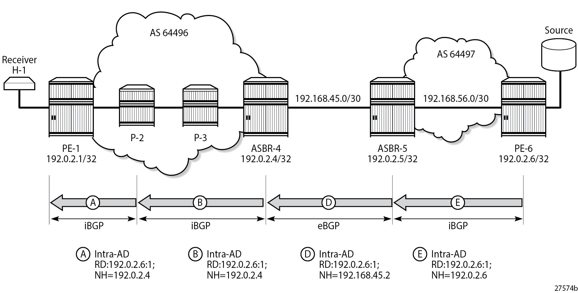
PE-1 receives the route, and imports the route into VPRN 1 as the route target extended community matches the community configured in the MVPN context of the VPRN. PE-1 now uses the PTA contained within the intra-AD route to instantiate the provider tunnel.
The following output shows details of the MVPN intra-AD route received by PE-1, generated by PE-6.
# on PE-1:
*A:PE-1# show router bgp routes mvpn-ipv4 type intra-ad originator-ip 192.0.2.6 hunt
===============================================================================
 BGP Router ID:192.0.2.1        AS:64496       Local AS:64496
===============================================================================
 Legend -
 Status codes  : u - used, s - suppressed, h - history, d - decayed, * - valid
                 l - leaked, x - stale, > - best, b - backup, p - purge
 Origin codes  : i - IGP, e - EGP, ? - incomplete

===============================================================================
BGP MVPN-IPv4 Routes
===============================================================================
-------------------------------------------------------------------------------
RIB In Entries
-------------------------------------------------------------------------------
Route Type     : Intra-Ad
Route Dist.    : 192.0.2.6:1
Originator IP  : 192.0.2.6
Nexthop        : 192.0.2.4
Path Id        : None
From           : 192.0.2.2
Res. Nexthop   : 0.0.0.0
Local Pref.    : 100                    Interface Name : NotAvailable
Aggregator AS  : None                   Aggregator     : None
Atomic Aggr.   : Not Atomic             MED            : None
AIGP Metric    : None                   IGP Cost       : n/a
Connector      : None
Community      : target:64496:1
Cluster        : 192.0.2.2
Originator Id  : 192.0.2.4              Peer Router Id : 192.0.2.2
Origin         : IGP
Flags          : Used Valid Best
Route Source   : Internal
AS-Path        : 64497
Route Tag      : 0
Neighbor-AS    : 64497
DB Orig Val    : N/A                    Final Orig Val : N/A
Source Class   : 0                      Dest Class     : 0
Add Paths Send : Default
Last Modified  : 00h03m08s
VPRN Imported  : 1
-------------------------------------------------------------------------------
PMSI Tunnel Attributes :
Tunnel-type    : LDP P2MP LSP
Flags          : Type: RNVE(0) BM: 0 U: 0 Leaf: not required
MPLS Label     : 0
Root-Node      : 192.0.2.6              LSP-ID         : 8193
-------------------------------------------------------------------------------

-------------------------------------------------------------------------------
RIB Out Entries
-------------------------------------------------------------------------------
-------------------------------------------------------------------------------
Routes : 1
===============================================================================
P2MP LDP LSP Signaling
The PTA lists the tunnel type as a P2MP LDP LSP. A P2MP label mapping message is originated on PE-1, with LSP-ID 8193, and the root of the mLDP tree is PE-6: 192.0.2.6. However, PE-1 does not have a route to PE-6, because inter-AS model B VPNs do not require the system addresses of the PEs to be advertised into the neighboring AS.
The intra-AD MVPN route is used to determine the path of the label mapping message from PE-1 toward PE-6. This is comparable to the unicast routing case, where a VPN-IPv4 labeled route is used to determine the path to the source.
The BGP next-hop of the intra-AD route is the system address of ASBR-4, so this can be used as the root address of the mLDP LSP, and the actual root can be contained inside the label mapping message as an inner root. The inner root becomes an opaque value that is known to the originator and receiver of the label mapping message.
P2MP LDP Label Mapping shows the path taken by the label mapping message from PE-1 to PE-6.
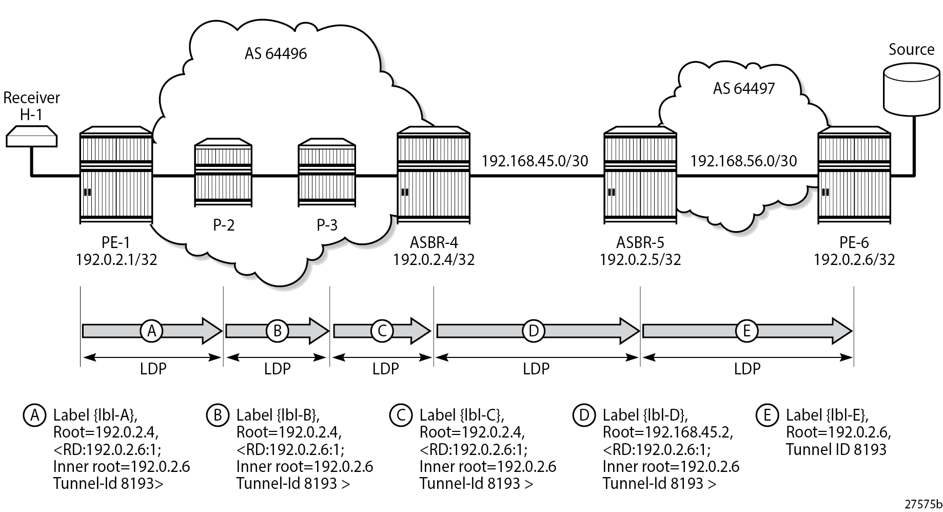
P-2 and P-3 do not have either a unicast or multicast (intra-AD) route toward PE-6, but have a route to the outer root ASBR-4. The label mapping message is forwarded from PE-1 to ASBR-4 via P-2 and P-3. At each hop, a label is allocated and a label binding entry is created. The labels can be different on PE-1, P-2, P-3, ASBR-4, ASBR-5, and PE-6. In this case, the labels are: {lbl-A}=524282, {lbl-B}=524283, {lbl-C}=524283, {lbl-D}=524279, and {lbl-E}=524279. In the following sections, the debug outputs are achieved using the following debug command:
debug
    router "Base"
        ldp
            peer <peer-ip-address>
                packet
                    label detail
                exit
            exit
        exit
    exit
exit
where <peer-ip-address> is the system address of the LDP peer.
LDP Hop PE-1 to P-2
The following output shows a debug of the P2MP label mapping message sent from PE-1 to P-2 upon receipt of the BGP MVPN intra-AD route.
# on PE-1:
9 2024/01/16 16:35:14.504 UTC MINOR: DEBUG #2001 Base LDP
"LDP: LDP
Send Label Mapping packet (msgId 86) to 192.0.2.2:0
Protocol version = 1
Label 524282 advertised for the following FECs
P2MP: root = 192.0.2.4, T: 8, L: 25 (RD: 0x1c00002060001, InnerRoot: 192.0.2.6 T: 1, L: 4, TunnelId: 8193)
"
The advertised label is 524282: the ingress label on PE-1. The P2MP root address is that of the BGP next-hop of the intra-AD route, that is, the ASBR-4 system address. T: 8 signifies that the FEC type is 8, VPN-recursive FEC, and L: 25 is the length of the opaque value. The opaque value contains the route distinguisher (RD) of the intra-AD route plus inner root 192.0.2.6 and a second opaque value: a type 1 (T:1) generic of length L = 4 bytes, containing the tunnel ID 8193.
The format of the type 8 opaque value aligns with the representation in mLDP Message Opaque Value Types in MVPN Model B:
<ASBR-4, Opaque type 8 <RD, PE-6 Opaque type 1 <Tunnel-ID>>>.
The LDP binding table of PE-1 is shown in the following output:
# on PE-1:
*A:PE-1# show router ldp bindings active p2mp ipv4 opaque-type vpn-recursive

===============================================================================
LDP Bindings (IPv4 LSR ID 192.0.2.1)
             (IPv6 LSR ID ::)
===============================================================================
Label Status:
        U - Label In Use, N - Label Not In Use, W - Label Withdrawn
        WP - Label Withdraw Pending, BU - Alternate For Fast Re-Route
        e - Label ELC
FEC Flags:
        LF - Lower FEC, UF - Upper FEC, M - Community Mismatch,
        BA - ASBR Backup FEC
===============================================================================
VPN Recursive with Generic IPv4 P2MP Bindings (Active)
===============================================================================
P2MP-Id                                     RD
InnerRootAddr                               Interface
RootAddr                                    Op
IngLbl                                      EgrLbl
EgrNH                                       EgrIf/LspId
-------------------------------------------------------------------------------
8193                                        192.0.2.6:1
192.0.2.6                                   73728
192.0.2.4                                   Pop
524282                                        --
  --                                          --

-------------------------------------------------------------------------------
No. of VPN Recursive with Generic IPv4 P2MP Active Bindings: 1
===============================================================================
This shows the VPN-recursive FEC binding with both root address of ASBR-4 and inner root of PE-6.
LDP Hop P-2 to P-3
On P-2, the label mapping messages received from PE-1 and advertised toward P-3 are shown in the following output.
# on P-2:
16 2024/01/16 16:35:15.745 UTC MINOR: DEBUG #2001 Base LDP
"LDP: LDP
Recv Label Mapping packet (msgId 86) from 192.0.2.1:0
Protocol version = 1
Label 524282 advertised for the following FECs
P2MP: root = 192.0.2.4, T: 8, L: 25 (RD: 0x1c00002060001, InnerRoot: 192.0.2.6 T: 1, L: 4, TunnelId: 8193)
"


17 2024/01/16 16:35:15.745 UTC MINOR: DEBUG #2001 Base LDP
"LDP: LDP
Send Label Mapping packet (msgId 84) to 192.0.2.3:0
Protocol version = 1
Label 524283 advertised for the following FECs
P2MP: root = 192.0.2.4, T: 8, L: 25 (RD: 0x1c00002060001, InnerRoot: 192.0.2.6 T: 1, L: 4, TunnelId: 8193)
"
The received message matches the advertised label from PE-1, and the label mapping message toward P-3 (192.0.2.3) is again a VPN-recursive FEC type. P-3 does not have a route to PE-6, but has a route to ASBR-4.
The following output shows the LDP label mapping for the VPN-recursive FEC on P-2.
# on P-2:
*A:P-2# show router ldp bindings active p2mp ipv4 opaque-type vpn-recursive

===============================================================================
LDP Bindings (IPv4 LSR ID 192.0.2.2)
             (IPv6 LSR ID ::)
===============================================================================
Label Status:
        U - Label In Use, N - Label Not In Use, W - Label Withdrawn
        WP - Label Withdraw Pending, BU - Alternate For Fast Re-Route
        e - Label ELC
FEC Flags:
        LF - Lower FEC, UF - Upper FEC, M - Community Mismatch,
        BA - ASBR Backup FEC
===============================================================================
VPN Recursive with Generic IPv4 P2MP Bindings (Active)
===============================================================================
P2MP-Id                                     RD
InnerRootAddr                               Interface
RootAddr                                    Op
IngLbl                                      EgrLbl
EgrNH                                       EgrIf/LspId
-------------------------------------------------------------------------------
8193                                        192.0.2.6:1
192.0.2.6                                   Unknw
192.0.2.4                                   Swap
524283                                      524282
192.168.12.1                                1/1/c2/1

-------------------------------------------------------------------------------
No. of VPN Recursive with Generic IPv4 P2MP Active Bindings: 1
===============================================================================
The following debug messages show the received and transmitted LDP label mapping message on P-3. The received label matches the advertised label from the previous debug output for P-2.
# on P-3:
1 2024/01/16 16:35:14.764 UTC MINOR: DEBUG #2001 Base LDP
"LDP: LDP
Recv Label Mapping packet (msgId 84) from 192.0.2.2:0
Protocol version = 1
Label 524283 advertised for the following FECs
P2MP: root = 192.0.2.4, T: 8, L: 25 (RD: 0x1c00002060001, InnerRoot: 192.0.2.6 T: 1, L: 4, TunnelId: 8193)
"


2 2024/01/16 16:35:14.764 UTC MINOR: DEBUG #2001 Base LDP
"LDP: LDP
Send Label Mapping packet (msgId 80) to 192.0.2.4:0
Protocol version = 1
Label 524283 advertised for the following FECs
P2MP: root = 192.0.2.4, T: 8, L: 25 (RD: 0x1c00002060001, InnerRoot: 192.0.2.6 T: 1, L: 4, TunnelId: 8193)
"
Again, the VPN-recursive FEC on P-3 is shown in the following output:
# on P-3:
*A:P-3# show router ldp bindings active p2mp ipv4 opaque-type vpn-recursive

===============================================================================
LDP Bindings (IPv4 LSR ID 192.0.2.3)
             (IPv6 LSR ID ::)
===============================================================================
Label Status:
        U - Label In Use, N - Label Not In Use, W - Label Withdrawn
        WP - Label Withdraw Pending, BU - Alternate For Fast Re-Route
        e - Label ELC
FEC Flags:
        LF - Lower FEC, UF - Upper FEC, M - Community Mismatch,
        BA - ASBR Backup FEC
===============================================================================
VPN Recursive with Generic IPv4 P2MP Bindings (Active)
===============================================================================
P2MP-Id                                     RD
InnerRootAddr                               Interface
RootAddr                                    Op
IngLbl                                      EgrLbl
EgrNH                                       EgrIf/LspId
-------------------------------------------------------------------------------
8193                                        192.0.2.6:1
192.0.2.6                                   Unknw
192.0.2.4                                   Swap
524283                                      524283
192.168.23.1                                1/1/c2/1

-------------------------------------------------------------------------------
No. of VPN Recursive with Generic IPv4 P2MP Active Bindings: 1
===============================================================================
ASBR-4
ASBR-4 is the root of the mLDP tree within AS 64496. Upon receipt of an mLDP label mapping message containing this FEC element, ASBR-4 recognizes that it is the root and that the opaque value is a VPN-recursive opaque value. ASBR-4 parses the VPN-recursive opaque value and extracts the root value: PE-6 plus the RD.
ASBR-4 does not have a unicast route to PE-6, so it must use the multicast VPN intra-AD route. This route contains an NLRI that has the IP address of PE-6, along with the BGP next-hop. As there may be multiple valid MVPN intra-ADs held by ASBR-4, the RD extracted from the mLDP label mapping message is used as a match to identify the MVPN intra-AD route held in the ASBR FIB.
ASBR-4 creates an mLDP mapping message containing a VPN-recursive FEC whose opaque value has the inner root address of PE-6, and a root address of ASBR-5.
The following output shows the label mapping messages at ASBR-4.
# on ASBR-4:
12 2024/01/16 16:35:14.922 UTC MINOR: DEBUG #2001 Base LDP
"LDP: LDP
Recv Label Mapping packet (msgId 80) from 192.0.2.3:0
Protocol version = 1
Label 524283 advertised for the following FECs
P2MP: root = 192.0.2.4, T: 8, L: 25 (RD: 0x1c00002060001, InnerRoot: 192.0.2.6 T: 1, L: 4, TunnelId: 8193)
"


13 2024/01/16 16:35:14.923 UTC MINOR: DEBUG #2001 Base LDP
"LDP: Binding
Sending Label mapping label 524279 for P2MP: root = 192.168.45.2, T: 8, L: 25 (RD: 0x1c00002060001, InnerRoot: 192.0.2.6 T: 1, L: 4, TunnelId: 8193)
 to peer 192.0.2.5:0."


14 2024/01/16 16:35:14.923 UTC MINOR: DEBUG #2001 Base LDP
"LDP: LDP
Send Label Mapping packet (msgId 78) to 192.0.2.5:0
Protocol version = 1
Label 524279 advertised for the following FECs
P2MP: root = 192.168.45.2, T: 8, L: 25 (RD: 0x1c00002060001, InnerRoot: 192.0.2.6 T: 1, L: 4, TunnelId: 8193)
"
The label mapping message uses a format of the opaque type listed in mLDP Message Opaque Value Types in MVPN Model B, where the new root is now ASBR-5, and the inner root address remains the PE-6 system address:
<ASBR-5, Opaque type 8 <RD, PE-6 Opaque type 1 <Tunnel-ID>>>.
At ASBR-4, the root changes from ASBR-4 to ASBR-5. ASBR-4 essentially becomes a leaf node with root at ASBR-5.
The following output shows the label binding output at ASBR-4.
# on ASBR-4:
*A:ASBR-4# show router ldp bindings active p2mp ipv4 opaque-type vpn-recursive

===============================================================================
LDP Bindings (IPv4 LSR ID 192.0.2.4)
             (IPv6 LSR ID ::)
===============================================================================
Label Status:
        U - Label In Use, N - Label Not In Use, W - Label Withdrawn
        WP - Label Withdraw Pending, BU - Alternate For Fast Re-Route
        e - Label ELC
FEC Flags:
        LF - Lower FEC, UF - Upper FEC, M - Community Mismatch,
        BA - ASBR Backup FEC
===============================================================================
VPN Recursive with Generic IPv4 P2MP Bindings (Active)
===============================================================================
P2MP-Id                                     RD
InnerRootAddr                               Interface
RootAddr                                    Op
IngLbl                                      EgrLbl
EgrNH                                       EgrIf/LspId
-------------------------------------------------------------------------------
8193                                        192.0.2.6:1
192.0.2.6                                   Unknw
192.0.2.4 (LF)                              Push
  --                                        524283
192.168.34.1                                1/1/c2/1

8193                                        192.0.2.6:1
192.0.2.6                                   Unknw
192.168.45.2 (UF)                           Swap
524279                                      Stitched
  --                                          --

-------------------------------------------------------------------------------
No. of VPN Recursive with Generic IPv4 P2MP Active Bindings: 2
===============================================================================
The label binding message received from the downstream router P-3 is known as the Lower FEC (LF). The label binding message forwarded to ASBR-5 has allocated a label and is stored as the Upper FEC (UF).
To create a non-segmented mLDP LSP, a label swap action must occur at ASBR-4, where the leaf of the P2MP LSP that has a root at ASBR-5 must be stitched to the P2MP LSP that has a root at ASBR-4 and leaf on PE-1. To achieve this, the UF label is swapped to the LF label. They are stitched using the common RD. If there are multiple lower FECs for the same RD at the ASBR, then ASBR-4 acts as a replication point. This stitching action can be seen in the EgrLbl field of the UF entry.
ASBR-5
ASBR-5 receives the label mapping message from ASBR-4. This contains a label mapping plus the opaque value with a VPN-recursive FEC type 8. The root address is a local address, so the recursive FEC is parsed and the root address of PE-6 is extracted.
# on ASBR-5:
12 2024/01/16 16:35:13.506 UTC MINOR: DEBUG #2001 Base LDP
"LDP: LDP
Recv Label Mapping packet (msgId 78) from 192.0.2.4:0
Protocol version = 1
Label 524279 advertised for the following FECs
P2MP: root = 192.168.45.2, T: 8, L: 25 (RD: 0x1c00002060001, InnerRoot: 192.0.2.6 T: 1, L: 4, TunnelId: 8193)
"
ASBR-5 has a route to the PE-6 address 192.0.2.6 in the forwarding table.
ASBR-5 therefore constructs an mLDP label mapping message with FEC element containing the address of PE-6 as the root address. This is seen in the following output, where the opaque type is type 1. The opaque value is the tunnel ID contained in the original intra-AD MVPN route.
# on ASBR-5:
13 2024/01/16 16:35:13.506 UTC MINOR: DEBUG #2001 Base LDP
"LDP: LDP
Send Label Mapping packet (msgId 72) to 192.0.2.6:0
Protocol version = 1
Label 524279 advertised for the following FECs
P2MP: root = 192.0.2.6, T: 1, L: 4, TunnelId: 8193
"
This compares to the representation for opaque type 1 from mLDP Message Opaque Value Types in MVPN Model B:
<PE-6 Opaque type 1 <Tunnel-ID>>.
The following output taken from ASBR-5 shows the stitching of the recursive label mapping received from ASBR-4 to the generic IPv4 label mapping sent to PE-6. The LF label received from ASBR-4 (524279) is stitched to the UF label (524279) via the common root address of 192.0.2.6.
# on ASBR-5:
*A:ASBR-5# show router ldp bindings active p2mp ipv4

===============================================================================
LDP Bindings (IPv4 LSR ID 192.0.2.5)
             (IPv6 LSR ID ::)
===============================================================================
Label Status:
        U - Label In Use, N - Label Not In Use, W - Label Withdrawn
        WP - Label Withdraw Pending, BU - Alternate For Fast Re-Route
        e - Label ELC
FEC Flags:
        LF - Lower FEC, UF - Upper FEC, M - Community Mismatch,
        BA - ASBR Backup FEC
===============================================================================
LDP Generic IPv4 P2MP Bindings (Active)
===============================================================================
P2MP-Id                                     Interface
RootAddr                                    Op
IngLbl                                      EgrLbl
EgrNH                                       EgrIf/LspId
-------------------------------------------------------------------------------
8193                                        Unknw
192.0.2.6 (UF)                              Swap
524279                                      Stitched
  --                                          --

-------------------------------------------------------------------------------
No. of Generic IPv4 P2MP Active Bindings: 1
===============================================================================
---snip---
===============================================================================
VPN Recursive with Generic IPv4 P2MP Bindings (Active)
===============================================================================
P2MP-Id                                     RD
InnerRootAddr                               Interface
RootAddr                                    Op
IngLbl                                      EgrLbl
EgrNH                                       EgrIf/LspId
-------------------------------------------------------------------------------
8193                                        192.0.2.6:1
192.0.2.6                                   Unknw
192.168.45.2 (LF)                           Push
  --                                        524279
192.168.45.1                                1/1/c2/1

-------------------------------------------------------------------------------
No. of VPN Recursive with Generic IPv4 P2MP Active Bindings: 1
===============================================================================
---snip---
LDP Hop ASBR-5 to PE-6
For completeness, the following debug output on PE-6 shows the receipt of the mLDP label mapping message from ASBR-5, which contains the system address of PE-6 as the root address.
# on PE-6:
8 2024/01/16 16:35:14.819 UTC MINOR: DEBUG #2001 Base LDP
"LDP: LDP
Recv Label Mapping packet (msgId 72) from 192.0.2.5:0
Protocol version = 1
Label 524279 advertised for the following FECs
P2MP: root = 192.0.2.6, T: 1, L: 4, TunnelId: 8193
"
The label binding output on PE-6 shows that the operation is a push operation. This is expected because PE-6 is the root node of the P2MP LSP.
# on PE-6:
*A:PE-6# show router ldp bindings active p2mp ipv4 opaque-type generic

===============================================================================
LDP Bindings (IPv4 LSR ID 192.0.2.6)
             (IPv6 LSR ID ::)
===============================================================================
Label Status:
        U - Label In Use, N - Label Not In Use, W - Label Withdrawn
        WP - Label Withdraw Pending, BU - Alternate For Fast Re-Route
        e - Label ELC
FEC Flags:
        LF - Lower FEC, UF - Upper FEC, M - Community Mismatch,
        BA - ASBR Backup FEC
===============================================================================
LDP Generic IPv4 P2MP Bindings (Active)
===============================================================================
P2MP-Id                                     Interface
RootAddr                                    Op
IngLbl                                      EgrLbl
EgrNH                                       EgrIf/LspId
-------------------------------------------------------------------------------
8193                                        73728
192.0.2.6                                   Push
  --                                        524279
192.168.56.1                                1/1/c2/1

-------------------------------------------------------------------------------
No. of Generic IPv4 P2MP Active Bindings: 1
===============================================================================
PIM status
Traffic is forwarded into multicast group 239.255.0.1 from the source using address 172.16.67.2.
An IGMPv3 group membership report is generated by the receiver H-1 and is shown on PE-1.
# on PE-1:
*A:PE-1# show router 1 igmp group
===============================================================================
IGMP Interface Groups
===============================================================================

(172.16.67.2,239.255.0.1)                                 UpTime: 0d 00:03:20
    Fwd List  : int-PE-1-VPRN-1-H-1
-------------------------------------------------------------------------------
Entries : 1
===============================================================================
---snip---
The status of the PIM group for VPRN 1 for group 239.255.0.1 is shown in the following output.
# on PE-1:
*A:PE-1# show router 1 pim group

===============================================================================
Legend:  A = Active   S = Standby
===============================================================================
PIM Groups ipv4
===============================================================================
Group Address               Type                Spt Bit  Inc Intf       No.Oifs
   Source Address              RP                  State    Inc Intf(S)
-------------------------------------------------------------------------------
239.255.0.1                 (S,G)                        mpls-if-73728  1
   172.16.67.2
-------------------------------------------------------------------------------
Groups : 1
===============================================================================
The incoming interface is an MPLS interface: mpls-if-73728. This is a PIM tunnel interface, as shown in the following output:
# on PE-1:
*A:PE-1# show router 1 pim tunnel-interface

===============================================================================
PIM Interfaces ipv4
===============================================================================
Interface                        Originator Address   Adm  Opr  Transport Type
-------------------------------------------------------------------------------
mpls-if-73728                    192.0.2.6            Up   Up   Rx-IPMSI
mpls-virt-if-1005857             192.0.2.1            Up   Up   Tx-IPMSI
-------------------------------------------------------------------------------
Interfaces : 2
===============================================================================
The originator address is 192.0.2.6, which is the root address of the mLDP tunnel on PE-6-the non-segmented mLDP tunnel.
For completeness, the PIM status of the group 239.255.0.1 on PE-6 is as follows:
# on PE-6:
*A:PE-6# show router 1 pim group

===============================================================================
Legend:  A = Active   S = Standby
===============================================================================
PIM Groups ipv4
===============================================================================
Group Address               Type                Spt Bit  Inc Intf       No.Oifs
   Source Address              RP                  State    Inc Intf(S)
-------------------------------------------------------------------------------
239.255.0.1                 (S,G)                        int-PE-6-VPRN* 1
   172.16.67.2
-------------------------------------------------------------------------------
Groups : 1
===============================================================================
* indicates that the corresponding row element may have been truncated.
Conclusion
Inter-AS multicast within a VPRN can be achieved using non-segmented mLDP trees. This chapter provides the configuration for inter-AS model B MVPN. The example also shows the associated commands, debug, and outputs, which can be used for verifying and troubleshooting.