Rosen MVPN Inter-AS Option B
This chapter provides information about Rosen MVPN: Inter-AS Option B configurations.
Topics in this chapter include:
Applicability
This chapter was initially written for SR OS Release 11.0.R3. The CLI in the current edition is based on SR OS Release 23.10.R1. Knowledge of the Nokia multicast and Layer 3 VPN concepts are assumed throughout this document.
Overview
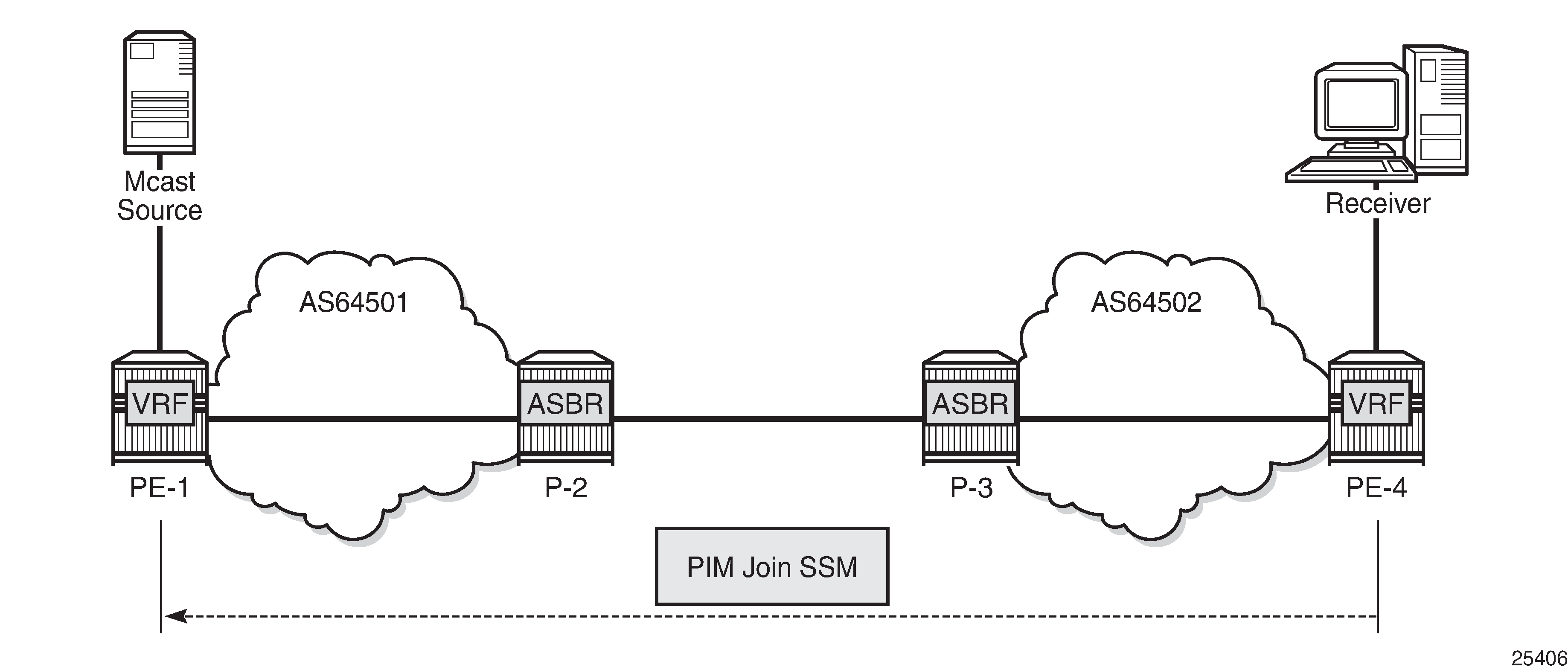
This chapter covers a basic technology overview, the network topology and configuration examples which are used for multicast virtual private network (MVPN) inter-autonomous system (AS) option B. The Inter-AS MVPN feature allows the setup of multicast distribution trees (MDTs) spanning multiple autonomous systems.
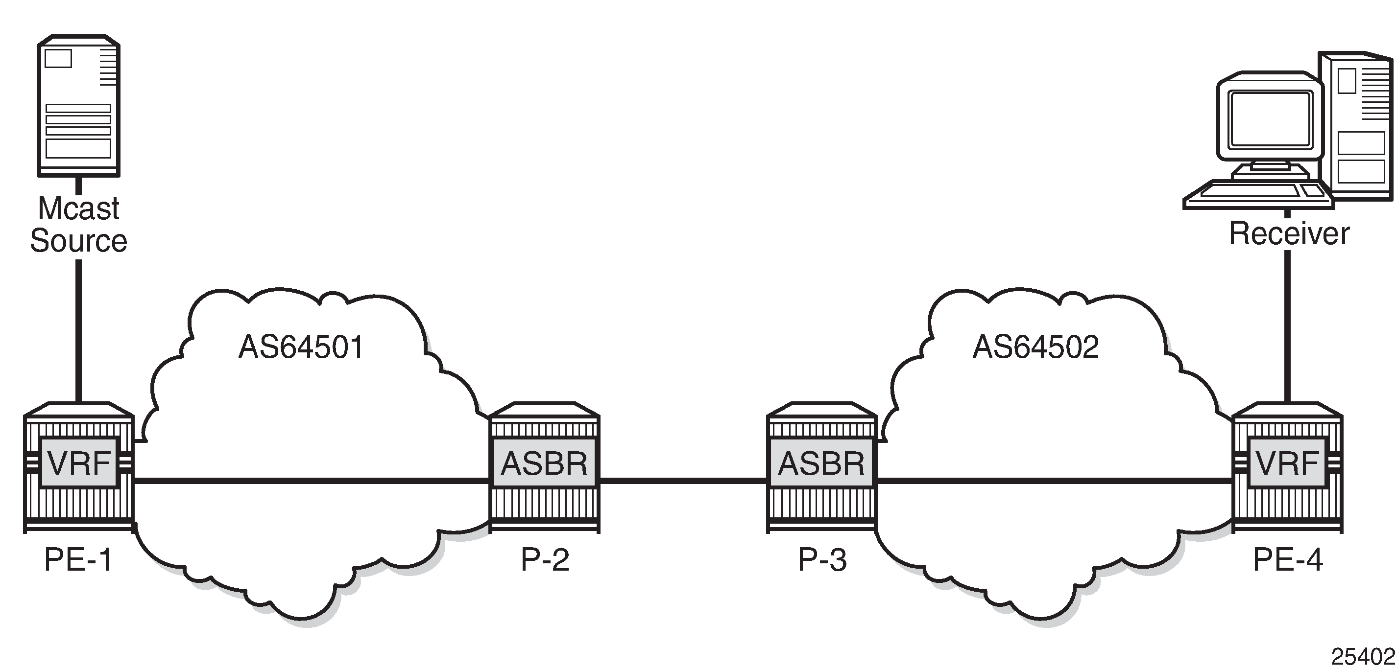
This chapter covers Rosen MVPN Inter-AS support (Option-B). Inter-AS Option B is supported for protocol independent multicast (PIM) source-specific multicast (SSM) with Rosen MVPN using multicast distribution tree (MDT) subsequent address family indicator (SAFI), the border gateway protocol (BGP) connector attribute and PIM reverse path forwarding (RPF) vector.
The following assumptions are made:
PE-1 is the sender PE because the multicast source is directly connected to this router.
PE-4 is the receiver PE because the multicast receiver is directly connected to this router.
P-2 and P-3 are ASBR routers according to the Inter-AS model.
The multicast receiver and source can be indirectly connected to PE routers via CE routers, but for the core multicast distribution, these variations are conceptually the same. For simplicity, the PE and P router configurations are provided.
There are several challenges which have to be solved to make the complete inter-AS solution operational:
Challenge 1:
In case of Inter-AS MVPN Option B, routing information toward the source PE is not available in a remote AS domain because IGP routes are not exchanged between ASs.
As a result, a PIM-P join would never be sent upstream (from the receiver PE to the sender PE in a different AS). However, the PIM-P join has to be propagated from PE-4 to PE-1. Therefore, a solution is required to issue PIM-P join and perform RPF.
Solution:
Use a PIM reverse path forwarding (RPF) vector (RPFV) to propagate PIM-P over multiple segments. In this example there are three segments:
PE-4 -> ASBR P-3
ASBR P-3 -> ASBR P-2
ASBR P-2 -> PE-1
The RPF vector is added to a PIM join by the PE router when the following option is enabled:
# on PE-4
configure router pim rpfv ?
  - no rpfv [core] [mvpn]
  - rpfv core mvpn
  - rpfv core
  - rpfv mvpn

 <core>               : Proxy RPF vector for core
 <mvpn>               : Proxy RPF vector for inter-AS rosen mvpn
The mvpn keyword enables ‟mvpn RPF vector” processing for Inter-AS Option B MVPN based on RFC 5496 and RFC 6513. If a core RPF vector is received, it is dropped before a message is processed.
All routers on the multicast traffic transport path must have this option enabled to allow RPF vector processing. If the option is not enabled, the RPF vector is dropped and the PIM join is processed as if the RPF vector is not present.
Details about RPF vector can be found in the following RFCs: 5496, 5384, 6513.
Challenge 2:
With Inter-AS MVPN Option B, the BGP next-hop is modified by the local and remote ASBRs during re-advertisement of VPN IPv4 routes. When the BGP next-hop is changed, information about the originator of the prefix is lost when the advertisement reaches the receiver PE node. Therefore, a solution is required to do a successful RPF check for the VPN source at receiver VPRN.
This challenge does not apply to Model C because in Model C the BGP next-hop for VPN routes is not updated.
Solution:
The transitive BGP connector attribute is added and used to advertise an address of a sender PE node which is carried inside a VPN IPv4 update. The BGP connector attribute allows the sender PE address information to be available to the receiver PE so that a receiver PE is able to associate VPN IPv4 advertisement to the corresponding source PE.
Inter-AS Option B works when the following criteria are met:
Rosen MVPN is used with PIM SSM
BGP MDT-SAFI address family is used
PIM RPF vector is configured
BGP connector attribute is used for VPN-IPv4 updates
SR OS inter-AS Option B is designed to be standard compliant based on the following RFCs:
RFC 5384, The Protocol Independent Multicast (PIM) Join Attribute Format
RFC 5496, The Reverse Path Forwarding (RPF) Vector TLV
RFC 6513, Multicast in MPLS/BGP IP VPNs
The following signaling stages can be identified when Inter-AS MVPN is configured:
Stage 1 - BGP core signaling
Stage 2 - Core PIM signaling
Stage 3 - Customer PIM signalling
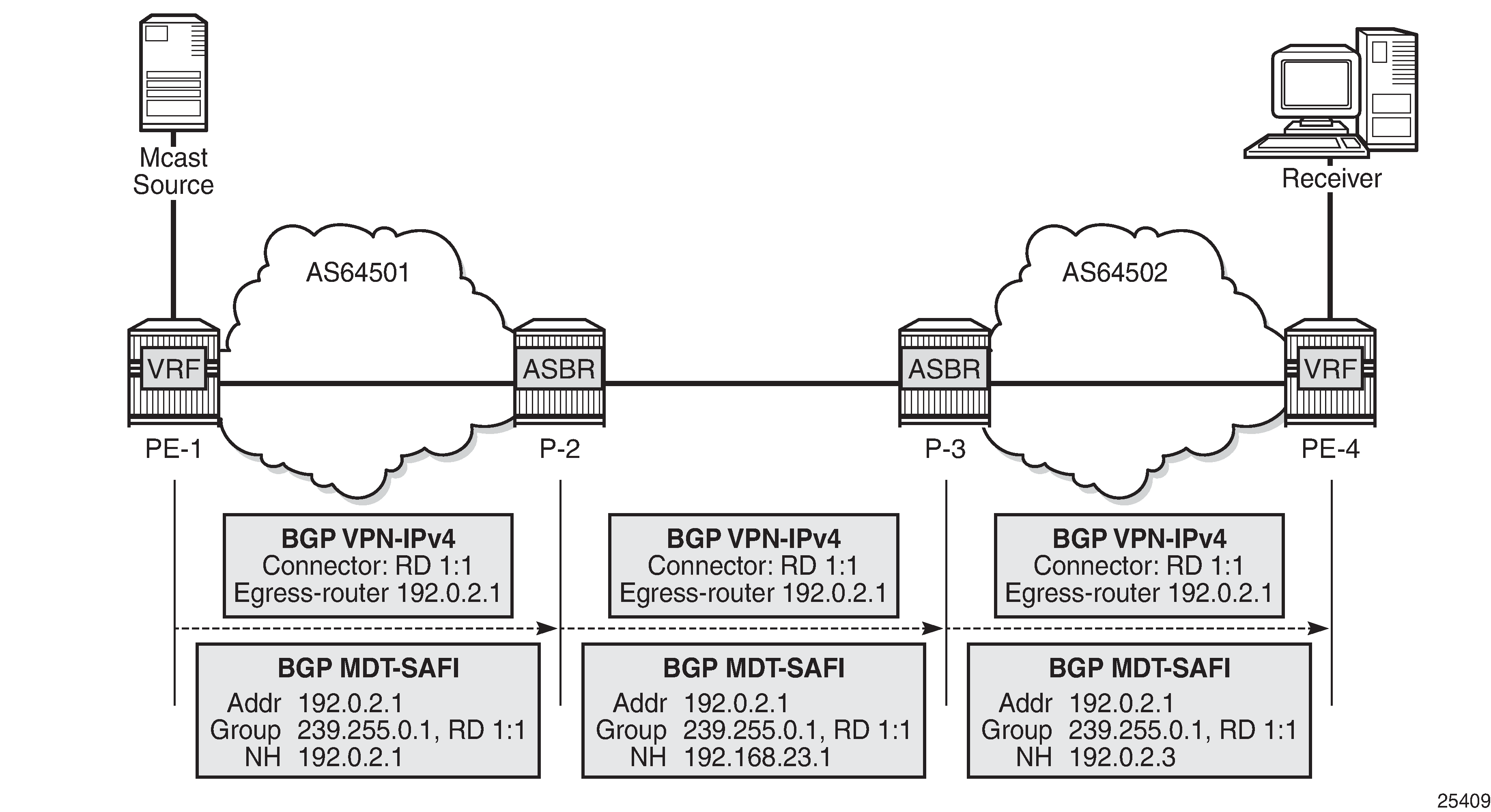
Stage 1 - BGP core signaling
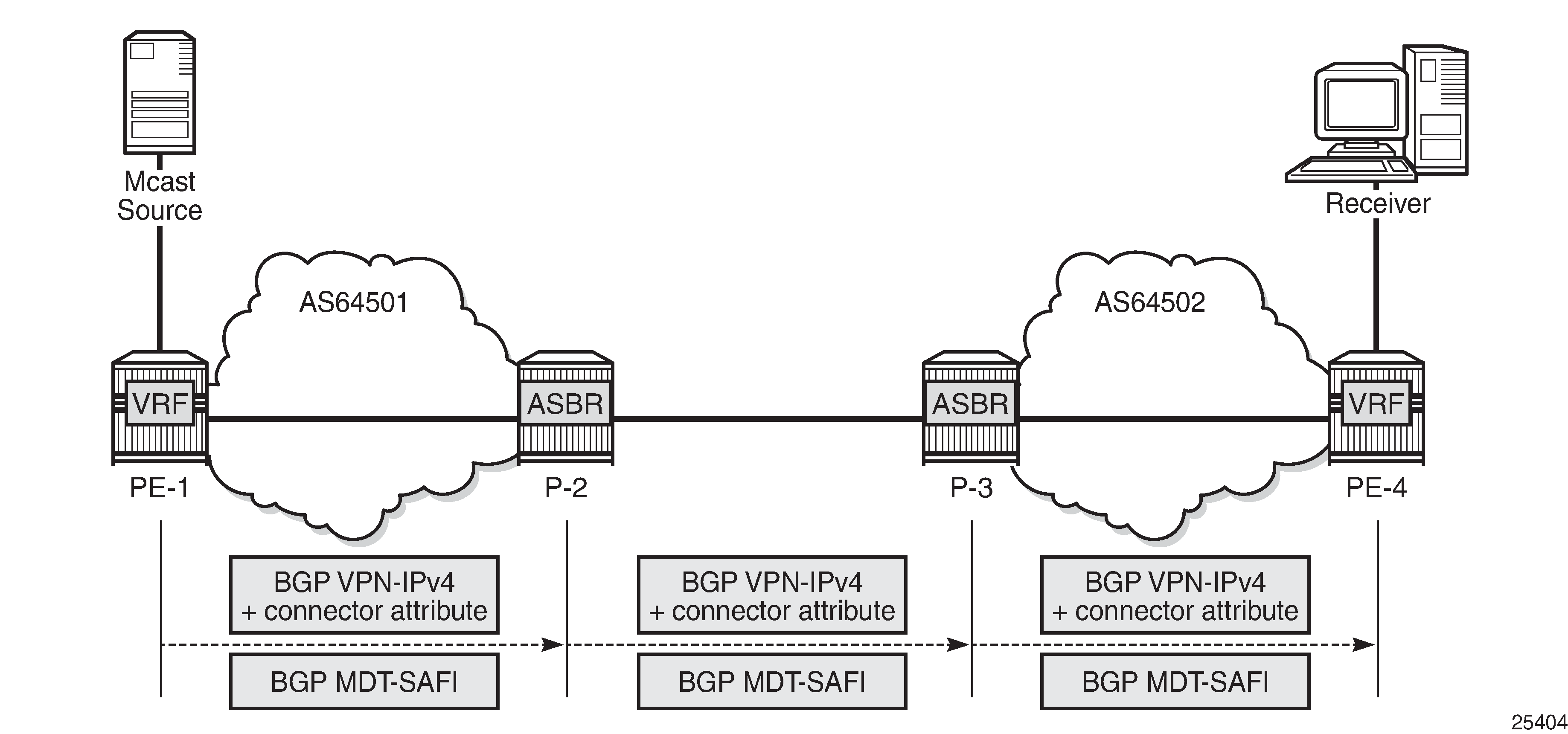
The sender PE sends VPN-IPv4 and MDT-SAFI BGP updates for this particular MVPN:
Every ASBR propagates VPN-IPv4 and MDT-SAFI BGP updates:
Next hop (NH) attribute is modified every time
Connector attribute stays untouched
When this stage is completed, all routers have information necessary:
to start PIM signaling in the core network (PIM-P) to prepare the default MDT
to start PIM signaling of customer multicast streams (PIM-C) inside the VPN
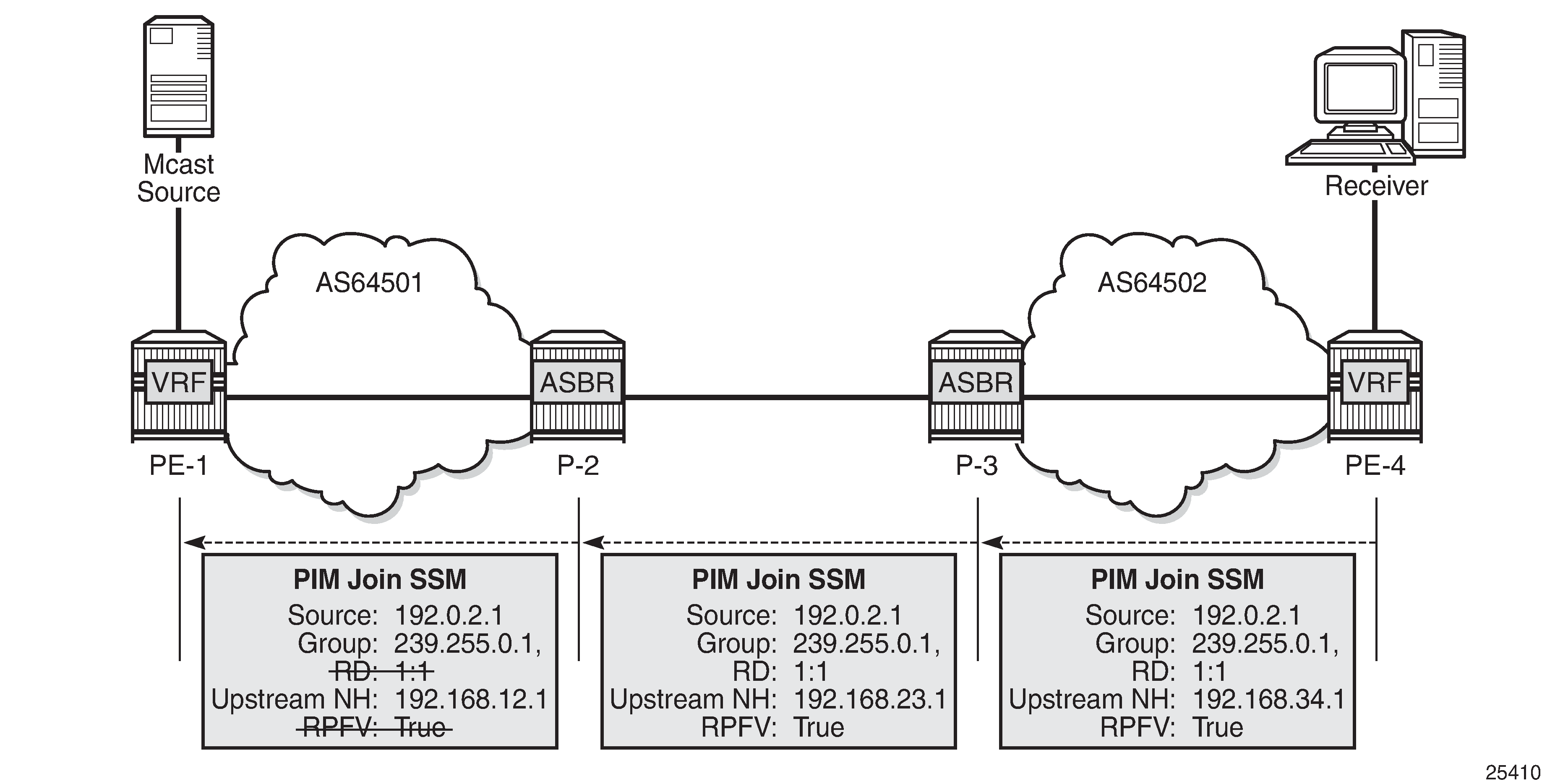
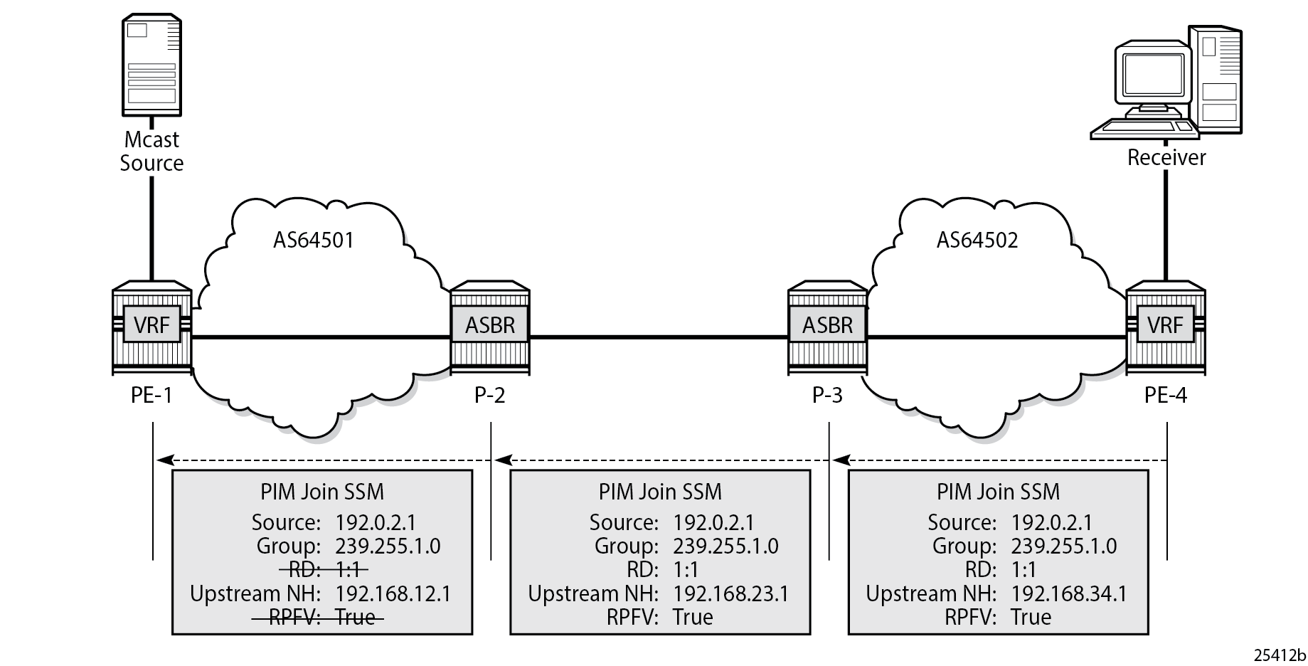
Stage 2 - Core PIM signaling
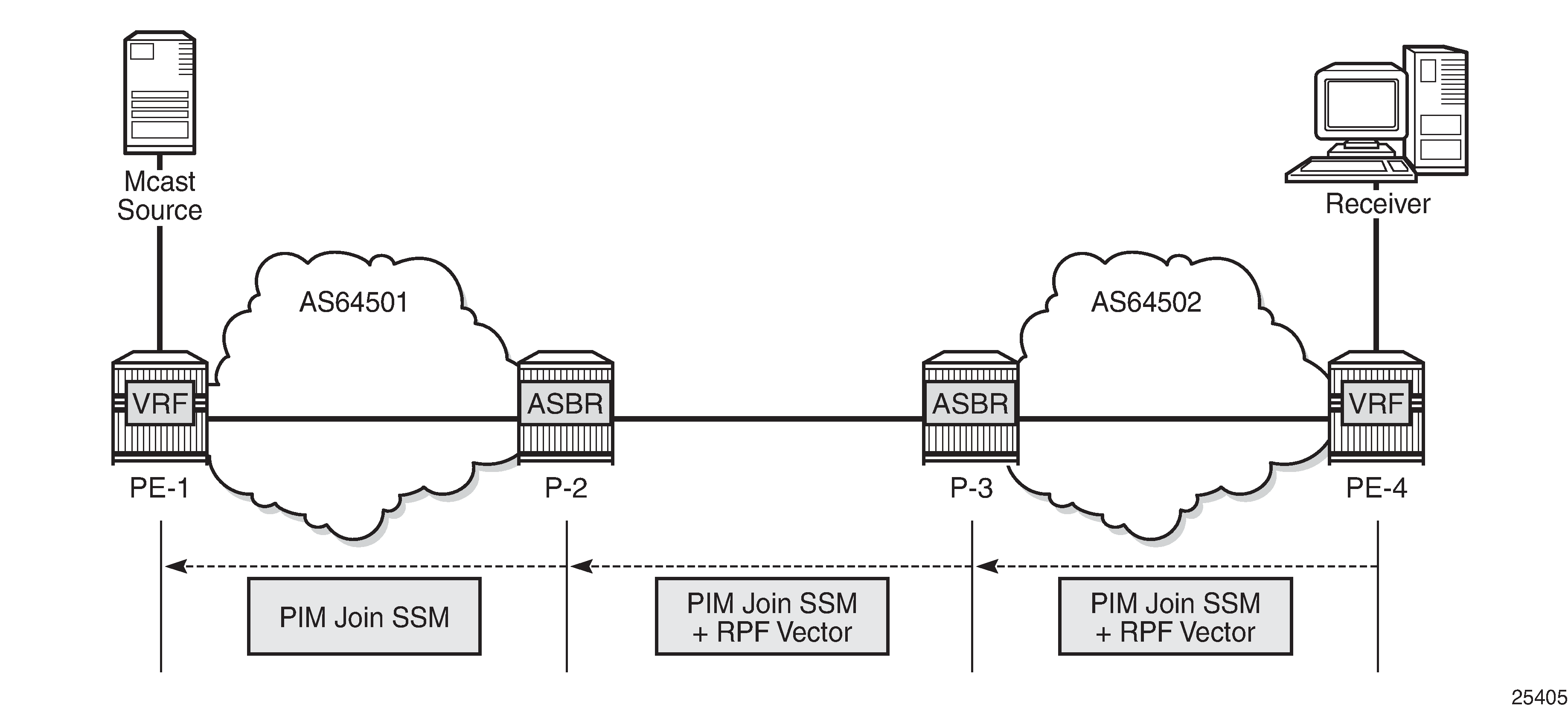
PE-4 determines the reverse path to the source based on the RPF vector (ASBR P-3 IP address) and not based on the IP address of the multicast source (PE-1) which is unknown to PE-4.
PE-4 inserts an RPF vector and sends a PIM-P join to the immediate next-hop to reach ASBR P-3. Intermediate P-routers (if present) do not change the RPF vector.
P-3 finds itself in the RPF vector and has to make a decision based on MDT-SAFI BGP table:
P-3 determines the reverse path to the multicast source based on the RPF vector (ASBR P-2 IP address).
If the multicast source and the NH do not match, P-3 has to use the RPFV.
P-3 modifies the PIM-P join received from PE-4 with ASBR P-2’s IP address as the upstream (taken from next hop MDT-SAFI network layer reachability information (NLRI)).
P-2 can match the source IP with the NH in BGP MDT-SAFI. Therefore, there is no need for the RPF vector to be used.
P-2 removes the RPF vector and sends a normal PIM-P join toward PE-1.
When this stage is completed, the default MDT is established for this MVPN and PE routers have the necessary information to start PIM signaling inside the VPRN (PIM-C).
Stage 3 - Customer PIM signaling
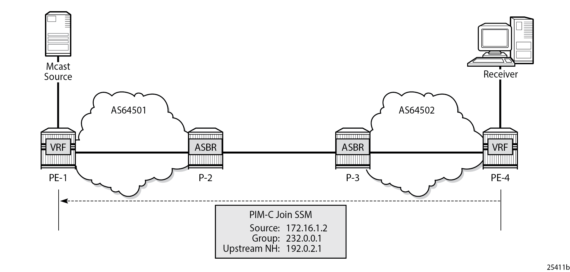
A PIM-C join is sent to the source PE using the existing tunnel infrastructure to the RPF neighbor PE-1 provided by the BGP connector attribute of the vpn-ipv4 route of the multicast source.
When this stage is completed, the customer multicast flows throughout the network in a default MDT.
Stage 4 - The multicast stream threshold is reached.
This stage is optional and applicable when S-PMSI instance and S-PMSI threshold are configured.
The process is similar to the default MDT setup:
PE-4 determines the reverse path to the source based on the RPF vector (ASBR P-3’s IP address) and not based on the IP address of the multicast source (PE-1) which is unknown to PE-4.
PE-4 inserts an RPF vector and sends a PIM-P Join to the immediate next hop to reach ASBR P-3.
Figure 6. PIM-P Signaling Steps for Data MDT
Intermediate P-routers (if present) do not change the RPF vector.
P-3 finds itself in the RPF vector and has to make a decision based on the MDT-SAFI BGP table:
P-3 determines the reverse path to the multicast source based on the RPF Vector (ASBR P-2’s IP address).
If the multicast source and the NH do not match, P-3 has to use the RPFV.
P-3 modifies the PIM-P join received from PE-4 with ASBR P-2’s IP address as upstream (taken from next hop MDT-SAFI NLRI).
P-2 can match the source IP with the NH in the BGP MDT-SAFI. Therefore, there is no need for the RPF vector to be used.
P-2 removes the RPF vector and sends a normal PIM-P join toward PE-1.
When this optional stage is completed, the customer multicast traffic flows through a dedicated Data MDT.
The SR OS implementation was also designed to interoperate with Cisco routers’ Inter-AS implementations that do not fully comply with the RFC 5384 and RFC 5496.
When the following option is enabled:
configure router pim rpfv mvpnCisco routers need to be configured to include rd in an RPF vector using the following command for interoperability:
ip multicast vrf <name> rpf proxy rd vectorConfiguration
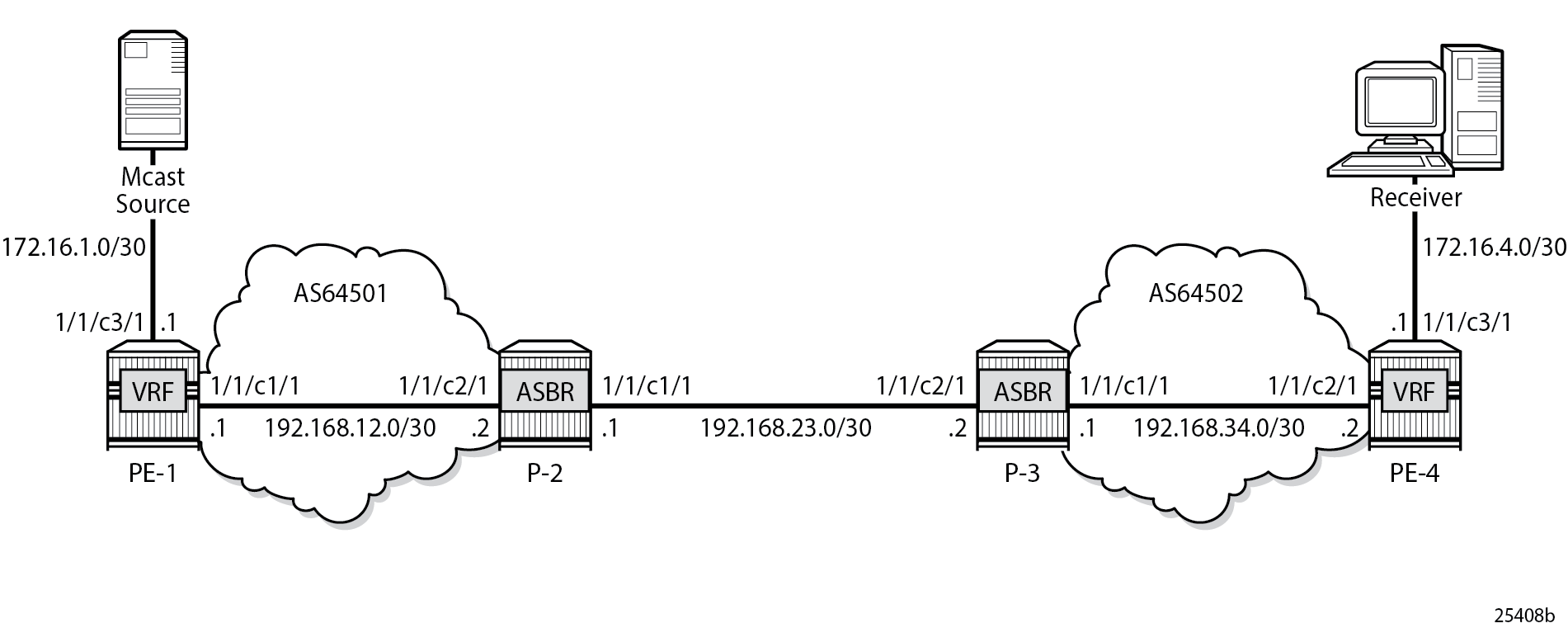
The example topology is shown in Example Topology Details.
The following components are used in the example scenario:
VPRN 1
Customer multicast group is 232.0.0.0/8
Default MDT multicast group is 239.255.0.1
Data MDT multicast group is 239.255.1.0/24
Multicast source is 172.16.1.2
PE-x routers have system IP addresses 192.0.2.x
P-x routers have system IP addresses 192.0.2.x
Interface between Router A and B has IP address 192.168.AB.x
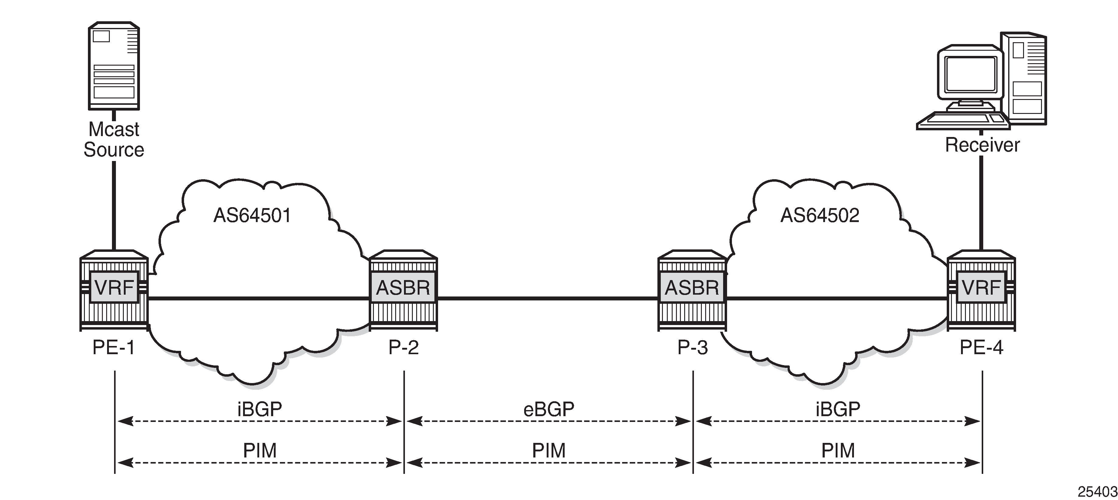
Global BGP configuration for PE-1 router using the mdt-safi family with an iBGP neighbor to P-2. The system interface IP address is used for the iBGP session.
# on PE-1
configure
    router
        bgp
            group "iBGP"
                family vpn-ipv4 mdt-safi
                type internal
                neighbor 192.0.2.2
                    next-hop-self
                exit
            exit
        exit
The global BGP configuration for P-2 router is using the mdt-safi family with an iBGP neighbor to PE-1 and an eBGP neighbor to P-3. The system interface IP address is used for the iBGP session and the network interface IP address is used for the eBGP session.
# on P-2
configure
    router
        bgp
            enable-inter-as-vpn
            group "eBGP"
                family vpn-ipv4 mdt-safi
                neighbor 192.168.23.2
                    type external
                    peer-as 64502
                exit
            exit
            group "iBGP"
                family vpn-ipv4 mdt-safi
                neighbor 192.0.2.1
                    next-hop-self
                    type internal
                exit
            exit
        exit
The global BGP configuration for the router P-3 is using the mdt-safi family with an iBGP neighbor to PE-4 and an eBGP neighbor to P-2. The system interface IP address is used for the iBGP session and the network interface IP address is used for the eBGP session.
# on P-3
configure
    router
        bgp
            enable-inter-as-vpn
            group "eBGP"
                family vpn-ipv4 mdt-safi
                neighbor 192.168.23.1
                    type external
                    peer-as 64501
                exit
            exit
            group "iBGP"
                family vpn-ipv4 mdt-safi
                neighbor 192.0.2.4
                    next-hop-self
                    type internal
                exit
            exit
        exit
The global BGP configuration for router PE-4 is using the mdt-safi family with an iBGP neighbor to P-3. The system interface IP address is used for the iBGP session.
# on PE-4
configure
    router
        bgp
            group "iBGP"
                family vpn-ipv4 mdt-safi
                type internal
                neighbor 192.0.2.3
                    next-hop-self
                exit
            exit
        exit
The global PIM configuration for all routers is as follows:
# on all routers
configure
    router
        pim
            rpf-table both
            apply-to non-ies
            rpfv mvpn
        exit
The VPRN configuration for the PE routers is as follows:
# on PE-1
configure
    service
        vprn 1 name "1" customer 1 create
            interface "int-PE-1-S-1" create
                address 172.16.1.1/30
                sap 1/1/c3/1 create
                exit
            exit
            bgp-ipvpn
                mpls
                    auto-bind-tunnel
                        resolution-filter
                            ldp
                            rsvp
                        exit
                        resolution filter
                    exit
                    route-distinguisher 1:1
                    vrf-target target:1:1
                    no shutdown
                exit
            exit
            pim
                apply-to all
                no shutdown
            exit
            mvpn
                auto-discovery mdt-safi
                provider-tunnel
                    inclusive
                        pim ssm 239.255.0.1
                        exit
                    exit
                    selective
                        data-threshold 232.0.0.0/8 1
                        pim-ssm 239.255.1.0/24
                    exit
                exit
                vrf-target unicast
                exit
            exit
            no shutdown
        exit
    exit
# on PE-4
configure
service
vprn 1 name "1" customer 1 create
interface "int-PE-4-H-4" create
address 172.16.4.1/30
sap 1/1/c3/1 create
exit
exit
bgp-ipvpn
mpls
auto-bind-tunnel
resolution-filter
ldp
rsvp
exit
resolution filter
exit
route-distinguisher 4:1
vrf-target target:1:1
no shutdown
exit
exit
igmp
interface "int-PE-4-H-4"
exit
exit
pim
apply-to all
no shutdown
exit
mvpn
auto-discovery mdt-safi
provider-tunnel
inclusive
pim ssm 239.255.0.1
exit
exit
selective
data-threshold 232.0.0.0/8 1
pim-ssm 239.255.1.0/24
exit
exit
vrf-target unicast
exit
exit
no shutdown
exit
exitMVPN Verification and Debugging
BGP Core Signaling
On PE-1, the debug router bgp update output shows the BGP update messages which are sent to P-2. The VPN-IPv4 update contains a connector attribute and the MDT-SAFI update is used for signaling multicast group 239.255.0.1.
1 2023/11/15 22:26:21.394 UTC MINOR: DEBUG #2001 Base Peer 1: 192.0.2.2
"Peer 1: 192.0.2.2: UPDATE
Peer 1: 192.0.2.2 - Send BGP UPDATE:
    Withdrawn Length = 0
    Total Path Attr Length = 79
    Flag: 0x90 Type: 14 Len: 33 Multiprotocol Reachable NLRI:
        Address Family VPN_IPV4
        NextHop len 12 NextHop 192.0.2.1
        172.16.1.0/30 RD 1:1 Label 524285 (Raw label 0x7fffd1)
    Flag: 0x40 Type: 1 Len: 1 Origin: 0
    Flag: 0x40 Type: 2 Len: 0 AS Path:
    Flag: 0x40 Type: 5 Len: 4 Local Preference: 100
    Flag: 0xc0 Type: 16 Len: 8 Extended Community:
        target:1:1
    Flag: 0xc0 Type: 20 Len: 14 Connector:
        RD 1:1, Egress-router 192.0.2.1
"

2 2023/11/15 22:26:21.394 UTC MINOR: DEBUG #2001 Base Peer 1: 192.0.2.2
"Peer 1: 192.0.2.2: UPDATE
Peer 1: 192.0.2.2 - Send BGP UPDATE:
    Withdrawn Length = 0
    Total Path Attr Length = 62
    Flag: 0x90 Type: 14 Len: 26 Multiprotocol Reachable NLRI:
        Address Family MDT-SAFI
        NextHop len 4 NextHop 192.0.2.1
        [MDT-SAFI] Addr 192.0.2.1, Group 239.255.0.1, RD 1:1
    Flag: 0x40 Type: 1 Len: 1 Origin: 0
    Flag: 0x40 Type: 2 Len: 0 AS Path:
    Flag: 0x80 Type: 4 Len: 4 MED: 0
    Flag: 0x40 Type: 5 Len: 4 Local Preference: 100
    Flag: 0xc0 Type: 16 Len: 8 Extended Community:
        target:1:1
"
On P-2, the debug router bgp update output shows the BGP update messages which are sent to P-3. The VPN-IPv4 update contains an unmodified connector attribute and the MDT-SAFI update is used for signaling multicast group 239.255.0.1.
3 2023/11/15 22:26:37.914 UTC MINOR: DEBUG #2001 Base Peer 1: 192.168.23.2
"Peer 1: 192.168.23.2: UPDATE
Peer 1: 192.168.23.2 - Send BGP UPDATE:
    Withdrawn Length = 0
    Total Path Attr Length = 78
    Flag: 0x90 Type: 14 Len: 33 Multiprotocol Reachable NLRI:
        Address Family VPN_IPV4
        NextHop len 12 NextHop 192.168.23.1
        172.16.1.0/30 RD 1:1 Label 524285 (Raw label 0x7fffd1)
    Flag: 0x40 Type: 1 Len: 1 Origin: 0
    Flag: 0x40 Type: 2 Len: 6 AS Path:
        Type: 2 Len: 1 < 64501 >
    Flag: 0xc0 Type: 16 Len: 8 Extended Community:
        target:1:1
    Flag: 0xc0 Type: 20 Len: 14 Connector:
        RD 1:1, Egress-router 192.0.2.1
"

4 2023/11/15 22:26:37.914 UTC MINOR: DEBUG #2001 Base Peer 1: 192.168.23.2
"Peer 1: 192.168.23.2: UPDATE
Peer 1: 192.168.23.2 - Send BGP UPDATE:
    Withdrawn Length = 0
    Total Path Attr Length = 54
    Flag: 0x90 Type: 14 Len: 26 Multiprotocol Reachable NLRI:
        Address Family MDT-SAFI
        NextHop len 4 NextHop 192.168.23.1
        [MDT-SAFI] Addr 192.0.2.1, Group 239.255.0.1, RD 1:1
    Flag: 0x40 Type: 1 Len: 1 Origin: 0
    Flag: 0x40 Type: 2 Len: 6 AS Path:
        Type: 2 Len: 1 < 64501 >
    Flag: 0xc0 Type: 16 Len: 8 Extended Community:
        target:1:1
"
On P-3, the debug router bgp update output shows the BGP update messages which are sent to PE-4. The VPN-IPv4 update contains an unmodified connector attribute and the MDT-SAFI update is used for signaling multicast group 239.255.0.1.
7 2023/11/15 22:26:52.726 UTC MINOR: DEBUG #2001 Base Peer 1: 192.0.2.4
"Peer 1: 192.0.2.4: UPDATE
Peer 1: 192.0.2.4 - Send BGP UPDATE:
    Withdrawn Length = 0
    Total Path Attr Length = 85
    Flag: 0x90 Type: 14 Len: 33 Multiprotocol Reachable NLRI:
        Address Family VPN_IPV4
        NextHop len 12 NextHop 192.0.2.3
        172.16.1.0/30 RD 1:1 Label 524285 (Raw label 0x7fffd1)
    Flag: 0x40 Type: 1 Len: 1 Origin: 0
    Flag: 0x40 Type: 2 Len: 6 AS Path:
        Type: 2 Len: 1 < 64501 >
    Flag: 0x40 Type: 5 Len: 4 Local Preference: 100
    Flag: 0xc0 Type: 16 Len: 8 Extended Community:
        target:1:1
    Flag: 0xc0 Type: 20 Len: 14 Connector:
        RD 1:1, Egress-router 192.0.2.1
"

8 2023/11/15 22:26:52.726 UTC MINOR: DEBUG #2001 Base Peer 1: 192.0.2.4
"Peer 1: 192.0.2.4: UPDATE
Peer 1: 192.0.2.4 - Send BGP UPDATE:
    Withdrawn Length = 0
    Total Path Attr Length = 61
    Flag: 0x90 Type: 14 Len: 26 Multiprotocol Reachable NLRI:
        Address Family MDT-SAFI
        NextHop len 4 NextHop 192.0.2.3
        [MDT-SAFI] Addr 192.0.2.1, Group 239.255.0.1, RD 1:1
    Flag: 0x40 Type: 1 Len: 1 Origin: 0
    Flag: 0x40 Type: 2 Len: 6 AS Path:
        Type: 2 Len: 1 < 64501 >
    Flag: 0x40 Type: 5 Len: 4 Local Preference: 100
    Flag: 0xc0 Type: 16 Len: 8 Extended Community:
        target:1:1
"
The BGP tables on PE-1 and PE-4 are updated accordingly. The most interesting aspect here is the MDT-SAFI routes received.
PE-4 has one MDT-SAFI update received from PE-1. The next-hop was modified according to the Option-B model.
*A:PE-4# show router bgp neighbor 192.0.2.3 received-routes mdt-safi
===============================================================================
 BGP Router ID:192.0.2.4        AS:64502       Local AS:64502
===============================================================================
 Legend -
 Status codes  : u - used, s - suppressed, h - history, d - decayed, * - valid
                 l - leaked, x - stale, > - best, b - backup, p - purge
 Origin codes  : i - IGP, e - EGP, ? - incomplete

===============================================================================
BGP MDT-SAFI Routes
===============================================================================
Flag  Network                                            LocalPref   MED
      Nexthop                     Group-Addr                         IGP Cost
      As-Path                                                        Label
-------------------------------------------------------------------------------
u*>i  1:1:192.0.2.1                                      100         None
      192.0.2.3                   239.255.0.1                        -
64501
-------------------------------------------------------------------------------
Routes : 1
===============================================================================
PE-1 has one MDT-SAFI update received from PE-4. The next-hop was modified according to the Option B model.
*A:PE-1# show router bgp neighbor 192.0.2.2 received-routes mdt-safi
===============================================================================
 BGP Router ID:192.0.2.1        AS:64501       Local AS:64501
===============================================================================
 Legend -
 Status codes  : u - used, s - suppressed, h - history, d - decayed, * - valid
                 l - leaked, x - stale, > - best, b - backup, p - purge
 Origin codes  : i - IGP, e - EGP, ? - incomplete

===============================================================================
BGP MDT-SAFI Routes
===============================================================================
Flag  Network                                            LocalPref   MED
      Nexthop                     Group-Addr                         IGP Cost
      As-Path                                                        Label
-------------------------------------------------------------------------------
u*>i  4:1:192.0.2.4                                      100         None
      192.0.2.2                   239.255.0.1                        -
64502
-------------------------------------------------------------------------------
Routes : 1
===============================================================================
Core PIM Signaling
On PE-4, the debug router pim packet jp output shows the PIM join/prune message which is sent to P-3. This message contains the original source of the multicast traffic (PE-1: 192.0.2.1) and the RPF Vector (P-3: 192.0.2.3).
8 2023/11/15 22:29:34.986 UTC MINOR: DEBUG #2001 Base PIM[Instance 1 Base]
"PIM[Instance 1 Base]: Join/Prune
[000 08:02:57.070] PIM-TX ifId 2 ifName int-PE-4-P-3 0.0.0.0 -> 224.0.0.13 Length: 48
PIM Version: 2 Msg Type: Join/Prune Checksum: 0x3d2c
Upstream Nbr IP : 192.168.34.1 Resvd: 0x0, Num Groups 1, HoldTime 210
Group: 239.255.0.1/32 Num Joined Srcs: 1, Num Pruned Srcs: 0
Joined Srcs:
192.0.2.1/32 Flag S  <S,G> JA={rpfvMvpn 192.0.2.3 1:1}

"
On P-3, the debug router pim packet jp output shows the PIM join/prune message which is propagated to P-2. The source of multicast traffic is untouched while the RPF Vector is modified for Inter-AS propagation.
17 2023/11/15 22:29:34.950 UTC MINOR: DEBUG #2001 Base PIM[Instance 1 Base]
"PIM[Instance 1 Base]: Join/Prune
[000 08:02:45.990] PIM-TX ifId 2 ifName int-P-3-P-2 0.0.0.0 -> 224.0.0.13 Length: 48
PIM Version: 2 Msg Type: Join/Prune Checksum: 0x3286
Upstream Nbr IP : 192.168.23.1 Resvd: 0x0, Num Groups 1, HoldTime 210
Group: 239.255.0.1/32 Num Joined Srcs: 1, Num Pruned Srcs: 0
Joined Srcs:
192.0.2.1/32 Flag S  <S,G> JA={rpfvMvpn 192.168.23.1 1:1}

"
On P-2, the debug router pim packet jp output shows the PIM join/prune message which is propagated to PE-1. The source of the multicast traffic is untouched while the RPF Vector is not present anymore.
16 2023/11/15 22:29:35.559 UTC MINOR: DEBUG #2001 Base PIM[Instance 1 Base]
"PIM[Instance 1 Base]: Join/Prune
[000 08:02:44.680] PIM-TX ifId 2 ifName int-P-2-PE-1 0.0.0.0 -> 224.0.0.13 Length: 34
PIM Version: 2 Msg Type: Join/Prune Checksum: 0x563f
Upstream Nbr IP : 192.168.12.1 Resvd: 0x0, Num Groups 1, HoldTime 210
Group: 239.255.0.1/32 Num Joined Srcs: 1, Num Pruned Srcs: 0
Joined Srcs:
192.0.2.1/32 Flag S  <S,G>

"
As a result of this signaling, the default MDT is established between the two ASs. This can be checked with the show router pim group command.
The following PE-1 output shows the active multicast groups which are used as default MDT.
*A:PE-1# show router pim group

===============================================================================
Legend:  A = Active   S = Standby
===============================================================================
PIM Groups ipv4
===============================================================================
Group Address               Type                Spt Bit  Inc Intf       No.Oifs
   Source Address              RP                  State    Inc Intf(S)
-------------------------------------------------------------------------------
239.255.0.1                 (S,G)               spt      system         2
   192.0.2.1
239.255.0.1                 (S,G)               spt      int-PE-1-P-2   1
   192.0.2.4
-------------------------------------------------------------------------------
Groups : 2
===============================================================================
The following PE-4 output shows the active multicast groups which are used as default MDT:
*A:PE-4# show router pim group

===============================================================================
Legend:  A = Active   S = Standby
===============================================================================
PIM Groups ipv4
===============================================================================
Group Address               Type                Spt Bit  Inc Intf       No.Oifs
   Source Address              RP                  State    Inc Intf(S)
-------------------------------------------------------------------------------
239.255.0.1                 (S,G)               spt      int-PE-4-P-3   1
   192.0.2.1
239.255.0.1                 (S,G)               spt      system         2
   192.0.2.4
-------------------------------------------------------------------------------
Groups : 2
===============================================================================
The detailed information about the PIM-P group shows that the default MDT is used to deliver traffic. Key parameters such as the incoming/outgoing interfaces and non-zero traffic counters allow this conclusion to be made.
PE-4 has the incoming interface ‟int-PE-4-P-3”, and outgoing interface ‟system”, as follows:
*A:PE-4# show router pim group detail

===============================================================================
PIM Source Group ipv4
===============================================================================
Group Address      : 239.255.0.1
Source Address     : 192.0.2.1
RP Address         : 0
Advt Router        : 192.0.2.3

Upstream RPFV Nbr  : 192.168.34.1
RPFV Type          : Mvpn 1:1           RPFV Proxy         : 192.0.2.3

Flags              : spt                Type               : (S,G)
Mode               : sparse
MRIB Next Hop      : 192.168.34.1
MRIB Src Flags     : remote
Keepalive Timer Exp: 0d 00:03:24
Up Time            : 0d 00:02:21        Resolved By        : rtable-u

Up JP State        : Joined             Up JP Expiry       : 0d 00:00:39
Up JP Rpt          : Not Joined StarG   Up JP Rpt Override : 0d 00:00:00

Register State     : No Info
Reg From Anycast RP: No

Rpf Neighbor       : 192.168.34.1
Incoming Intf      : int-PE-4-P-3
Outgoing Intf List : system

Curr Fwding Rate   : 0.000 kbps
Forwarded Packets  : 6                  Discarded Packets  : 0
Forwarded Octets   : 468                RPF Mismatches     : 0
Spt threshold      : 0 kbps             ECMP opt threshold : 7
Admin bandwidth    : 1 kbps

---snip---

-------------------------------------------------------------------------------
Groups : 2
===============================================================================
PE-1 has incoming the interface ‟system”, and outgoing interfaces ‟system, int-PE-1-P-2”, as follows:
*A:PE-1# show router pim group detail

===============================================================================
PIM Source Group ipv4
===============================================================================
Group Address      : 239.255.0.1
Source Address     : 192.0.2.1
RP Address         : 0
Advt Router        : 192.0.2.1
Flags              : spt                Type               : (S,G)
Mode               : sparse
MRIB Next Hop      :
MRIB Src Flags     : self
Keepalive Timer Exp: 0d 00:03:08
Up Time            : 0d 00:02:55        Resolved By        : rtable-m

Up JP State        : Joined             Up JP Expiry       : 0d 00:00:04
Up JP Rpt          : Not Joined StarG   Up JP Rpt Override : 0d 00:00:00

Register State     : No Info
Reg From Anycast RP: No

Rpf Neighbor       :
Incoming Intf      : system
Outgoing Intf List : system, int-PE-1-P-2

Curr Fwding Rate   : 0.000 kbps
Forwarded Packets  : 9                  Discarded Packets  : 0
Forwarded Octets   : 702                RPF Mismatches     : 0
Spt threshold      : 0 kbps             ECMP opt threshold : 7
Admin bandwidth    : 1 kbps

---snip---

-------------------------------------------------------------------------------
Groups : 2
===============================================================================
Customer PIM Signaling
The PIM-C Join is sent to the sender PE using the existing tunnel infrastructure.
On PE-4, the debug router 1 pim packet jp output shows the PIM join/prune message which is sent to PE-1 using PMSI interface ‟1-mt-239.255.0.1” inside VPRN 1. All of this information and more can be found in the output of the debug command.
1 2023/11/15 22:34:30.579 UTC MINOR: DEBUG #2001 vprn1 PIM[Instance 2 vprn1]
"PIM[Instance 2 vprn1]: Join/Prune
[000 08:07:52.660] PIM-TX ifId 5798466 ifName 1-mt-239.255.0.1 0.0.0.0 -> 224.0.0.13 Length: 34
PIM Version: 2 Msg Type: Join/Prune Checksum: 0x7dd5
Upstream Nbr IP : 192.0.2.1 Resvd: 0x0, Num Groups 1, HoldTime 210
Group: 232.0.0.1/32 Num Joined Srcs: 1, Num Pruned Srcs: 0
Joined Srcs:
172.16.1.2/32 Flag S  <S,G>

"
The detailed information about the PIM-C group for a particular VPRN shows that the default MDT is used to deliver traffic. For this purpose, the show router 1 pim group detail command is used. Key parameters such as the correct multicast group, correct incoming/outgoing interfaces and non-zero flow rate allow this conclusion to be made.
PE-1 has the incoming interface ‟int-PE-1-S-1”, and outgoing interface ‟1-mt-239.255.0.1”. If the threshold hasn’t been reached to set up a selective provider tunnel, only one outgoing interface is listed. To generate this output, the data threshold for the selective provider tunnel was temporarily raised to 100000 kbps in VPRN 1.
*A:PE-1# show router 1 pim group detail

===============================================================================
PIM Source Group ipv4
===============================================================================
Group Address      : 232.0.0.1
Source Address     : 172.16.1.2
RP Address         : 0
Advt Router        : 192.0.2.1
Flags              :                    Type               : (S,G)
Mode               : sparse
MRIB Next Hop      : 172.16.1.2
MRIB Src Flags     : direct
Keepalive Timer    : Not Running
Up Time            : 0d 00:03:56        Resolved By        : rtable-u

Up JP State        : Joined             Up JP Expiry       : 0d 00:00:00
Up JP Rpt          : Not Joined StarG   Up JP Rpt Override : 0d 00:00:00

Register State     : No Info
Reg From Anycast RP: No

Rpf Neighbor       : 172.16.1.2
Incoming Intf      : int-PE-1-S-1
Outgoing Intf List : 1-mt-239.255.0.1

Curr Fwding Rate   : 9325.072 kbps
Forwarded Packets  : 280801             Discarded Packets  : 0
Forwarded Octets   : 275746582          RPF Mismatches     : 0
Spt threshold      : 0 kbps             ECMP opt threshold : 7
Admin bandwidth    : 1 kbps
-------------------------------------------------------------------------------
Groups : 1
===============================================================================
PE-4 has the incoming interface ‟1-mt-239.255.0.1”, and outgoing interface ‟int-PE-4-H-4” to the receiving host. As long as there is no S-PMSI, the following output can be seen.
*A:PE-4# show router 1 pim group detail

===============================================================================
PIM Source Group ipv4
===============================================================================
Group Address      : 232.0.0.1
Source Address     : 172.16.1.2
RP Address         : 0
Advt Router        : 192.0.2.3
Flags              :                    Type               : (S,G)
Mode               : sparse
MRIB Next Hop      : 192.0.2.1
MRIB Src Flags     : remote
Keepalive Timer    : Not Running
Up Time            : 0d 00:04:02        Resolved By        : rtable-u

Up JP State        : Joined             Up JP Expiry       : 0d 00:00:57
Up JP Rpt          : Not Joined StarG   Up JP Rpt Override : 0d 00:00:00

Register State     : No Info
Reg From Anycast RP: No

Rpf Neighbor       : 192.0.2.1
Incoming Intf      : 1-mt-239.255.0.1
Outgoing Intf List : int-PE-4-H-4

Curr Fwding Rate   : 9305.432 kbps
Forwarded Packets  : 288185             Discarded Packets  : 0
Forwarded Octets   : 282997670          RPF Mismatches     : 0
Spt threshold      : 0 kbps             ECMP opt threshold : 7
Admin bandwidth    : 1 kbps
-------------------------------------------------------------------------------
Groups : 1
===============================================================================
When Multicast Stream Threshold is Reached
On PE-4, the debug router pim packet jp output shows the PIM join/prune message which is sent to P-3. This message contains the original source of the multicast traffic (PE-1: 192.0.2.1) and the RPF Vector (P-3: 192.0.2.3).
A new multicast group (239.255.1.0) is signaled for purposes of establishing the data MDT.
3 2023/11/15 22:40:51.643 UTC MINOR: DEBUG #2001 Base PIM[Instance 1 Base]
"PIM[Instance 1 Base]: Join/Prune
[000 08:14:13.730] PIM-TX ifId 2 ifName int-PE-4-P-3 0.0.0.0 -> 224.0.0.13 Length: 48
PIM Version: 2 Msg Type: Join/Prune Checksum: 0x3c2d
Upstream Nbr IP : 192.168.34.1 Resvd: 0x0, Num Groups 1, HoldTime 210
Group: 239.255.1.0/32 Num Joined Srcs: 1, Num Pruned Srcs: 0
Joined Srcs:
192.0.2.1/32 Flag S  <S,G> JA={rpfvMvpn 192.0.2.3 1:1}

"
On P-3, the debug router pim packet jp output shows the PIM join/prune message which is propagated to P-2. The source of multicast traffic is untouched while the RPF Vector is modified for Inter-AS propagation.
6 2023/11/15 22:40:51.606 UTC MINOR: DEBUG #2001 Base PIM[Instance 1 Base]
"PIM[Instance 1 Base]: Join/Prune
[000 08:14:02.650] PIM-TX ifId 2 ifName int-P-3-P-2 0.0.0.0 -> 224.0.0.13 Length: 48
PIM Version: 2 Msg Type: Join/Prune Checksum: 0x3187
Upstream Nbr IP : 192.168.23.1 Resvd: 0x0, Num Groups 1, HoldTime 210
Group: 239.255.1.0/32 Num Joined Srcs: 1, Num Pruned Srcs: 0
Joined Srcs:
192.0.2.1/32 Flag S  <S,G> JA={rpfvMvpn 192.168.23.1 1:1}

"
On P-2, the debug router pim packet jp output shows the PIM join/prune message which is propagated to PE-1. The source of multicast traffic is untouched while the RPF Vector is not present anymore.
6 2023/11/15 22:40:52.214 UTC MINOR: DEBUG #2001 Base PIM[Instance 1 Base]
"PIM[Instance 1 Base]: Join/Prune
[000 08:14:01.340] PIM-TX ifId 2 ifName int-P-2-PE-1 0.0.0.0 -> 224.0.0.13 Length: 34
PIM Version: 2 Msg Type: Join/Prune Checksum: 0x5540
Upstream Nbr IP : 192.168.12.1 Resvd: 0x0, Num Groups 1, HoldTime 210
Group: 239.255.1.0/32 Num Joined Srcs: 1, Num Pruned Srcs: 0
Joined Srcs:
192.0.2.1/32 Flag S  <S,G>

"
As a result of this signaling, the Data MDT is established between the two ASs. This can be checked with show router pim group command.
The PE-1 output shows an additional multicast group (239.255.1.0), which was created in the global routing table (GRT).
*A:PE-1# show router pim group

===============================================================================
Legend:  A = Active   S = Standby
===============================================================================
PIM Groups ipv4
===============================================================================
Group Address               Type                Spt Bit  Inc Intf       No.Oifs
   Source Address              RP                  State    Inc Intf(S)
-------------------------------------------------------------------------------
239.255.0.1                 (S,G)               spt      system         2
   192.0.2.1
239.255.0.1                 (S,G)               spt      int-PE-1-P-2   1
   192.0.2.4
239.255.1.0                 (S,G)                        system         1
   192.0.2.1
-------------------------------------------------------------------------------
Groups : 3
===============================================================================
The PE-4 output shows an additional multicast group (239.255.1.0), which was created in the GRT.
*A:PE-4# show router pim group

===============================================================================
Legend:  A = Active   S = Standby
===============================================================================
PIM Groups ipv4
===============================================================================
Group Address               Type                Spt Bit  Inc Intf       No.Oifs
   Source Address              RP                  State    Inc Intf(S)
-------------------------------------------------------------------------------
239.255.0.1                 (S,G)               spt      int-PE-4-P-3   1
   192.0.2.1
239.255.0.1                 (S,G)               spt      system         2
   192.0.2.4
239.255.1.0                 (S,G)                        int-PE-4-P-3   1
   192.0.2.1
-------------------------------------------------------------------------------
Groups : 3
===============================================================================
The detailed information about the PIM group in a VPRN shows that the data MDT is used to receive traffic instead of the default MDT.
The PE-4 output for multicast groups in a VPRN 1 has slightly changed: a new line ‟Incoming SPMSI Intf” was added. This indicates that the S-PMSI instance and dedicated Data MDT are used for this particular multicast group. The non-zero rate for the multicast flow is also an indication that multicast traffic is forwarded.
*A:PE-4# show router 1 pim group detail

===============================================================================
PIM Source Group ipv4
===============================================================================
Group Address      : 232.0.0.1
Source Address     : 172.16.1.2
RP Address         : 0
Advt Router        : 192.0.2.3
Flags              :                    Type               : (S,G)
Mode               : sparse
MRIB Next Hop      : 192.0.2.1
MRIB Src Flags     : remote
Keepalive Timer    : Not Running
Up Time            : 0d 00:02:15        Resolved By        : rtable-u

Up JP State        : Joined             Up JP Expiry       : 0d 00:00:44
Up JP Rpt          : Not Joined StarG   Up JP Rpt Override : 0d 00:00:00

Register State     : No Info
Reg From Anycast RP: No

Rpf Neighbor       : 192.0.2.1
Incoming Intf      : 1-mt-239.255.0.1
Incoming SPMSI Intf: 1-mt-239.255.0.1*
Outgoing Intf List : int-PE-4-H-4

Curr Fwding Rate   : 9340.784 kbps
Forwarded Packets  : 161563             Discarded Packets  : 0
Forwarded Octets   : 158654866          RPF Mismatches     : 0
Spt threshold      : 0 kbps             ECMP opt threshold : 7
Admin bandwidth    : 1 kbps
-------------------------------------------------------------------------------
Groups : 1
===============================================================================
The show router 1 pim s-pmsi detail command can also be used to verify existence of the S-PMSI instance for the VPRN 1. The output includes the multicast group inside the VPRN, the multicast source IP, the multicast group which is used for S-PMSI tunneling and the current forwarding rate.
*A:PE-4# show router 1 pim s-pmsi detail

===============================================================================
PIM Selective provider tunnels
===============================================================================
Md Source Address  : 192.0.2.1          Md Group Address   : 239.255.1.0
Number of VPN SGs  : 1                  Uptime             : 0d 00:02:12
MT IfIndex         : 5806657            Egress Fwding Rate : 9340.784 kbps
Multistream-Id     : 0

VPN Group Address  : 232.0.0.1
VPN Source Address : 172.16.1.2
State              : RX Joined
Expiry Timer       : 0d 00:01:55
===============================================================================
PIM Selective provider tunnels Interfaces : 1
===============================================================================
Conclusion
Inter-AS MVPN offers flexibility for the operators who can use it to provide additional value added services to their customers. Before implementing this feature in the network the following are required:
The RPF vector must be enabled on every router for inter-AS MVPN.
Can be used only with Rosen MVPN with PIM SSM and MDT SAFI.