NG-MVPN Sender-Only, Receiver-Only
This chapter provides information about next generation multicast virtual private network (NG-MVPN) sender-only and receiver-only configurations.
Topics in this chapter include:
Applicability
The sender-only/receiver-only feature as described in this chapter is supported in SR OS Release 11.0.R1, and later. The CLI in this edition is based on SR OS Release 23.10.R1.
Knowledge of the Nokia multicast and Layer 3 VPNs concepts are assumed throughout this document.
Overview
This example covers a basic technology overview, the network topology, and configuration examples which are used for the Multicast VPN (MVPN) sender-only, receiver-only feature.
By default, if multiple PE nodes form a peering relationship within a common MVPN instance, then each PE node originates a multicast tree locally toward the remaining PE nodes that are members of this MVPN instance. This behavior creates a full mesh of Inclusive-Provider Multicast Service Interfaces (I-PMSIs) across all PE nodes in the MVPN.
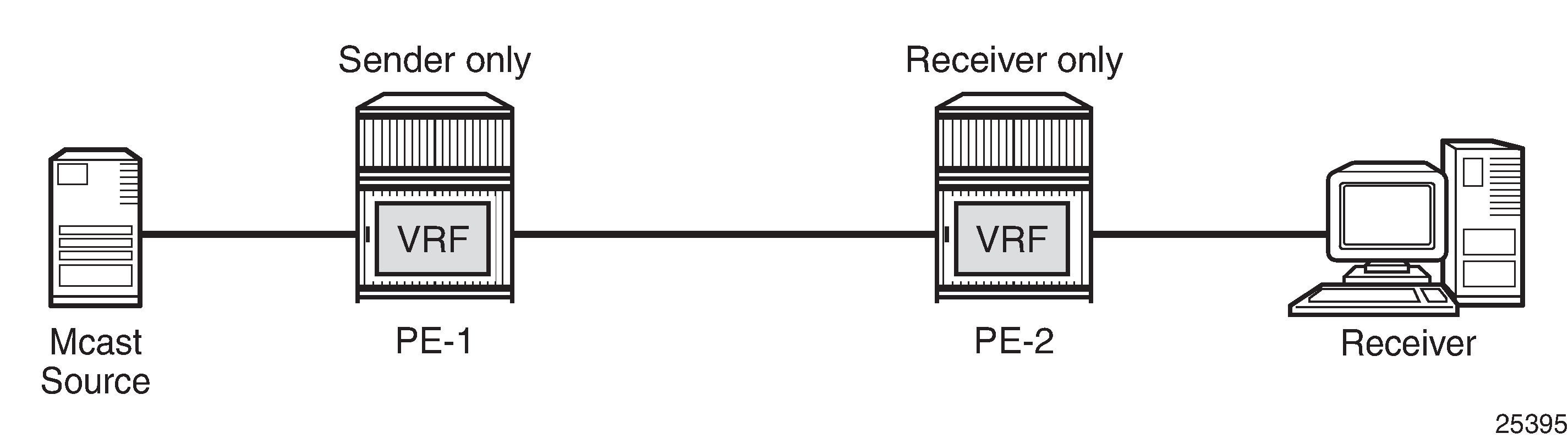
It is often the case that an MVPN has many sites with multicast receivers, but only a few sites that host either both receivers and sources, or sources only.
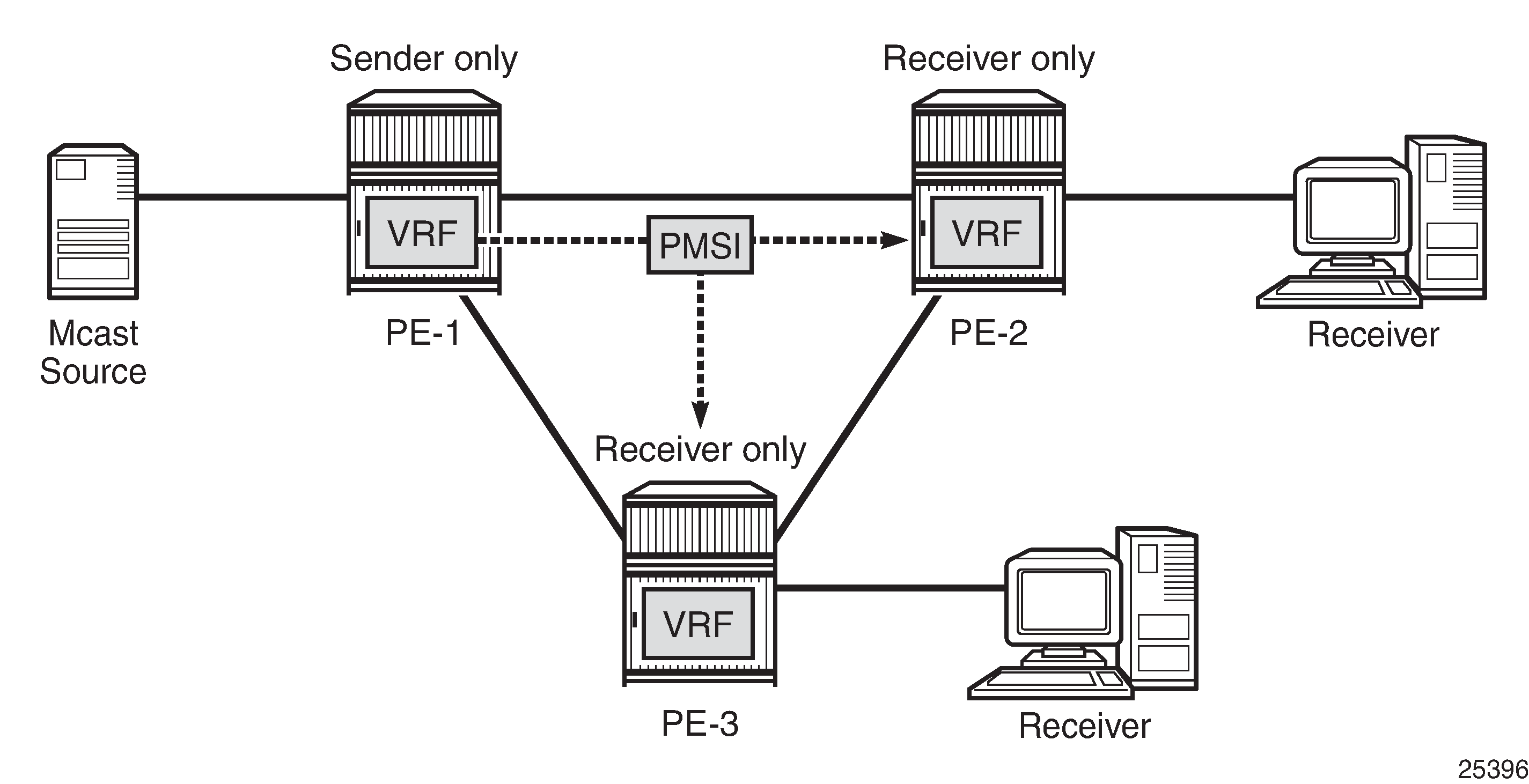
The MVPN sender-only/receiver-only feature optimizes control and data plane resources by preventing unnecessary I-PMSI meshing when a PE hosts multicast sources only, or multicast receivers only, for an MVPN. An example of such an optimization is presented in Optimized PMSI Structure.
The general rules to follow are:
For PE nodes that host only multicast sources for a specific MVPN, operators can now block these PEs, through configuration, from joining I-PMSIs from the other PEs in this MVPN.
For PE nodes that host only multicast receivers for a specific MVPN, operators can now block these PEs, through configuration, to set-up a local I-PMSI to the other PEs in this MVPN.
MVPN sender-only/receiver-only is supported with next generation MVPN for both IPv4 and IPv6 customer multicast using:
IPv4 RSVP-TE provider tunnels
IPv4 LDP provider tunnels
Extra attention should be given to the Bootstrap Router/Rendezvous Point (BSR/RP) placement when sender-only/receiver-only is enabled:
The RP should be at the sender-receiver or sender-only site so that (*,G) traffic can be sent over the tunnel
The BSR should be deployed at the sender-receiver site.
The BSR can be at a sender-only site if the RPs are at the same site.
(*,G) refers to an individual multicast stream indicating any source (*) and the multicast group (G) used by the stream.
Configuration
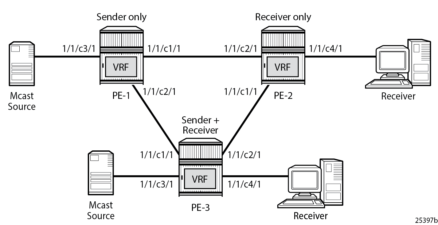
The example topology is shown in Example Topology.
To configure the sender-only/receiver-only feature, the following configuration command is used:
# on PE-1
configure
    service
        vprn 1 name "VPRN 1" customer 1 create
            mvpn
                mdt-type ?
  - mdt-type {sender-only|receiver-only|sender-receiver}
  - no mdt-type
sender-receiver is the default option and is visible using the info detail command.
This command restricts the MVPN instance to a specific role and provides an option to configure either a sender-only or receiver-only mode per PE node per service.
Parameters:
sender-only — MVPN has only senders connected to PE node.
receiver-only — MVPN has only receivers connected to PE node.
sender-receiver — MVPN has both sender and receivers connected to PE node.
Considerations:
Two general approaches for building MVPNs are covered in detail in this example:
Point-to-multipoint (P2MP) RSVP MVPNs
Multicast LDP (mLDP) MVPNs
IPv4 and IPv6 multicast streaming are used for every MVPN at the same time.
Basic principles of an MVPN including I-PMSI, S-PMSI, mLDP and P2MP RSVP are covered in the NG-MVPN Configuration with PIM and NG-MVPN Configuration with MPLSchapters of this guide.
PIM SSM is used for IPv4/IPv6 Customer (C)-multicast groups.
Initial Configuration
Step 1: The PE routers already have the following configuration:
Interfaces (IPv4/IPv6)
IGP (IS-IS or OSPF/OSPFv3)
LDP (IPv4 only suffices)
MPLS/RSVP
BGP
Step 2: The MPLS/RSVP configuration on PE-1 is as follows. An P2MP LSP template is created with an empty path, without explicit hops.
# on PE-1
configure
    router
        mpls
            interface "system"
                no shutdown
            exit
            interface "int-PE-1-PE-2"
                no shutdown
            exit
            interface "int-PE-1-PE-3"
                no shutdown
            exit
            path "EMPTY"
                no shutdown
            exit
            lsp-template "MVPN-P2MP-LSP" p2mp
                default-path "EMPTY"
                path-computation-method local-cspf
                no shutdown
            exit
            no shutdown
        exit
        rsvp no shutdown
    exit all
Step 3: The BGP configuration on PE-1 is as follows. No route reflector is used.
# on PE-1
configure
    router
        bgp
            enable-peer-tracking
            rapid-withdrawal
            rapid-update mvpn-ipv4 mvpn-ipv6
            group "INTERNAL"
                family vpn-ipv4 vpn-ipv6 mvpn-ipv4 mvpn-ipv6
                type internal
                neighbor 192.0.2.2
                exit
                neighbor 192.0.2.3
                exit
            exit
            no shutdown
        exit all
RSVP-Based MVPN Configuration
Step 1: Configure a basic MVPN using P2MP RSVP as a transport protocol for C-multicast groups.
For this setup, PE-2 and PE-3 are configured to receive the following multicast groups:
IPv4 group 232.0.0.1, source 172.16.1.2
IPv6 group FF3E::8000:1, source 2001:DB8:1::2
Step 2: Configure the MDT type for the MVPN.
Based on the example topology, PE-1 is configured as sender-only for the MVPN.
# on PE-1
configure
    service
        vprn 1 name "VPRN 1" customer 1 create
            description "RSVP-based MVPN"
            ecmp 2
            autonomous-system 64500
            ignore-nh-metric
            interface "int-PE-1-S-1" create
                description "to multicast source S-1"
                address 172.16.1.2/30
                ipv6
                    address 2001:db8:1::2/126
                exit
                sap 1/1/c3/1 create
                exit
            exit
            bgp-ipvpn
                mpls
                    auto-bind-tunnel
                        resolution-filter
                            ldp
                            rsvp
                        exit
                        resolution filter
                    exit
                    route-distinguisher 64500:101
                    vrf-target target:64500:1
                    no shutdown
                exit
            exit
            pim
                no ipv6-multicast-disable
                apply-to all
                no shutdown
            exit
            mvpn
                auto-discovery default
                c-mcast-signaling bgp
                mdt-type sender-only
                provider-tunnel
                    inclusive
                        rsvp
                            lsp-template "MVPN-P2MP-LSP"
                            no shutdown
                        exit
                    exit
                exit
                vrf-target unicast
                exit
            exit
            no shutdown
        exit all
Based on the example topology, PE-2 is configured as receiver-only for the MVPN. PE-2 has static joins for the IPv4 and IPv6 multicast groups:
group 232.0.0.1, source 172.16.1.2
group FF3E::8000:1, source 2001:DB8:1::2
# on PE-2
configure
    service
        vprn 1 name "VPRN 1" customer 1 create
            description "RSVP-based MVPN"
            ecmp 2
            autonomous-system 64500
            ignore-nh-metric
            interface "int-PE-2-H-2" create
                description "to receiver Host-2"
                address 172.16.2.2/30
                ipv6
                    address 2001:db8:2::2/126
                exit
                sap 1/1/c4/1 create
                exit
            exit
            bgp-ipvpn
                mpls
                    auto-bind-tunnel
                        resolution-filter
                            ldp
                            rsvp
                        exit
                        resolution filter
                    exit
                    route-distinguisher 64500:102
                    vrf-target target:64500:1
                    no shutdown
                exit
            exit
            igmp
                interface "int-PE-2-H-2"
                    static
                        group 232.0.0.1
                            source 172.16.1.2
                        exit
                    exit
                    no shutdown
                exit
                no shutdown
            exit
            mld
                interface "int-PE-2-H-2"
                    static
                        group ff3e::8000:1
                            source 2001:db8:1::2
                        exit
                    exit
                    no shutdown
                exit
                no shutdown
            exit
            pim
                no ipv6-multicast-disable
                apply-to all
                no shutdown
            exit
            mvpn
                auto-discovery default
                c-mcast-signaling bgp
                mdt-type receiver-only
                provider-tunnel
                    inclusive
                        rsvp
                            lsp-template "MVPN-P2MP-LSP"
                            no shutdown
                        exit
                    exit
                exit
                vrf-target unicast
                exit
            exit
            no shutdown
        exit all
Based on the example topology, PE-3 is configured as sender-receiver (default) for the MVPN. PE-3 has also static joins for the IPv4 and IPv6 multicast groups:
group 232.0.0.1, source 172.16.1.2
group FF3E::8000:1, source 2001:DB8:1::2
The interface to the local source for PE-3 is not configured in this example. PE-3 acts as a receiver, not as a sender. Nonetheless, it is configured as sender-receiver and that has its consequences for the I-PMSIs that are established.
# on PE-3
configure
    service
        vprn 1 name "VPRN 1" customer 1 create
            description "RSVP-based MVPN"
            ecmp 2
            autonomous-system 64500
            ignore-nh-metric
            interface "int-PE-3-H-3" create
                description "to receiver Host-3"
                address 172.16.3.2/30
                ipv6
                    address 2001:db8:3::2/126
                exit
                sap 1/1/c4/1 create
                exit
            exit
            bgp-ipvpn
                mpls
                    auto-bind-tunnel
                        resolution-filter
                            ldp
                            rsvp
                        exit
                        resolution filter
                    exit
                    route-distinguisher 64500:103
                    vrf-target target:64500:1
                    no shutdown
                exit
            exit
            igmp
                interface "int-PE-3-H-3"
                    static
                        group 232.0.0.1
                            source 172.16.1.2
                        exit
                    exit
                    no shutdown
                exit
                no shutdown
            exit
            mld
                interface "int-PE-3-H-3"
                    static
                        group ff3e::8000:1
                            source 2001:db8:1::2
                        exit
                    exit
                    no shutdown
                exit
                no shutdown
            exit
            pim
                no ipv6-multicast-disable
                apply-to all
                no shutdown
            exit
            mvpn
                auto-discovery default
                c-mcast-signaling bgp
                provider-tunnel
                    inclusive
                        rsvp
                            lsp-template "MVPN-P2MP-LSP"
                            no shutdown
                        exit
                    exit
                exit
                vrf-target unicast
                exit
            exit
            no shutdown
        exit all
The PIM instance must be shutdown before the mdt-type is modified; this leads to a multicast service disruption. Trying to change the mdt-type with PIM instance active results in the following message being displayed.
# on PE-1
configure service vprn 1 mvpn mdt-type receiver-only
MINOR: PIM #1100 PIM instance must be shutdown before changing this configuration
RSVP-Based MVPN Verification and Debugging
MDT-Type Verification
The status of the MVPN can be checked using the show router <service-number> mvpn command:
The output for PE-1, PE-2 and PE-3 is as follows:
*A:PE-1# show router 1 mvpn

===============================================================================
MVPN 1 configuration data
===============================================================================
signaling          : Bgp                  auto-discovery     : Default
UMH Selection      : Highest-Ip           SA withdrawn       : Disabled
intersite-shared   : Enabled              Persist SA         : Disabled
vrf-import         : N/A
vrf-export         : N/A
vrf-target         : unicast
C-Mcast Import RT  : target:192.0.2.1:2

ipmsi              : rsvp MVPN-P2MP-LSP
i-pmsi P2MP AdmSt  : Up
i-pmsi Tunnel Name : MVPN-P2MP-LSP-1-73728
enable-bfd-root    : false                enable-bfd-leaf    : false
Mdt-type           : sender-only
ipmsi UMH RM       : Disabled

BSR signalling     : none
Wildcard s-pmsi    : Disabled
Multistream-SPMSI  : Disabled
s-pmsi             : none
data-delay-interval: 3 seconds
enable-asm-mdt     : N/A
spmsi UMH RM       : Disabled

===============================================================================
*A:PE-2# show router 1 mvpn
===============================================================================
MVPN 1 configuration data
===============================================================================
signaling : Bgp auto-discovery : Default
UMH Selection : Highest-Ip SA withdrawn : Disabled
intersite-shared : Enabled Persist SA : Disabled
vrf-import : N/A
vrf-export : N/A
vrf-target : unicast
C-Mcast Import RT : target:192.0.2.2:2
ipmsi : rsvp MVPN-P2MP-LSP
i-pmsi P2MP AdmSt : Up
i-pmsi Tunnel Name : mpls-virt-if-1005857
enable-bfd-root : false enable-bfd-leaf : false
Mdt-type : receiver-only
ipmsi UMH RM : Disabled
BSR signalling : none
Wildcard s-pmsi : Disabled
Multistream-SPMSI : Disabled
s-pmsi : none
data-delay-interval: 3 seconds
enable-asm-mdt : N/A
spmsi UMH RM : Disabled
===============================================================================*A:PE-3# show router 1 mvpn
===============================================================================
MVPN 1 configuration data
===============================================================================
signaling : Bgp auto-discovery : Default
UMH Selection : Highest-Ip SA withdrawn : Disabled
intersite-shared : Enabled Persist SA : Disabled
vrf-import : N/A
vrf-export : N/A
vrf-target : unicast
C-Mcast Import RT : target:192.0.2.3:2
ipmsi : rsvp MVPN-P2MP-LSP
i-pmsi P2MP AdmSt : Up
i-pmsi Tunnel Name : MVPN-P2MP-LSP-1-73728
enable-bfd-root : false enable-bfd-leaf : false
Mdt-type : sender-receiver
ipmsi UMH RM : Disabled
BSR signalling : none
Wildcard s-pmsi : Disabled
Multistream-SPMSI : Disabled
s-pmsi : none
data-delay-interval: 3 seconds
enable-asm-mdt : N/A
spmsi UMH RM : Disabled
===============================================================================BGP Verification and Debugging
When the MDT type is changed, the BGP signaling is slightly modified to achieve the signaling optimization.
The PE router does not include the PMSI part in the Intra-AD BGP messages when the MVPN is configured with mdt-type receiver-only. The message flow is presented in RSVP-Based BGP Message Flow Between PE-1 and PE-2.
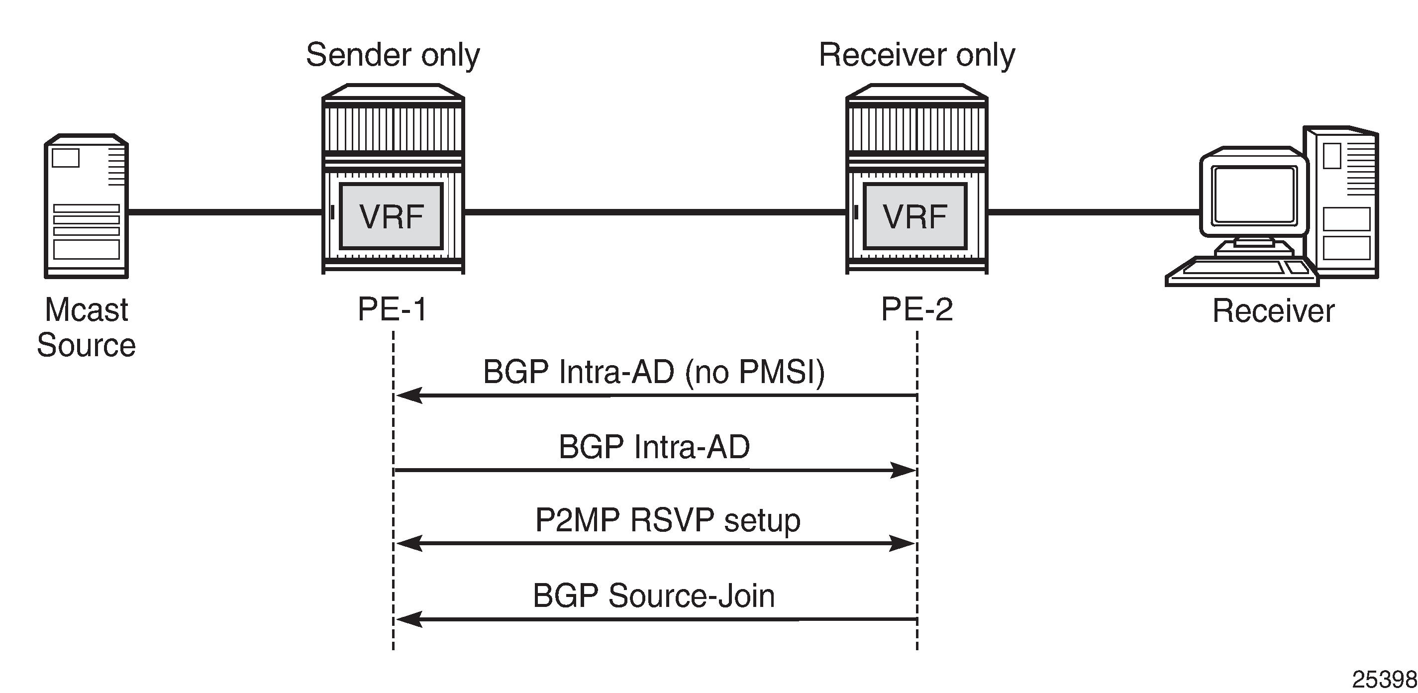
The following BGP debug output is taken from PE-2 and demonstrates the message flow between PE-1 and PE-2 for the MVPN-IPv4 address family.
There is no PMSI part in the BGP Intra-AD message sent by PE-2 (message 6), but the PMSI part is present in the BGP Intra-AD message received from sender-only PE-1 (message 1).
1 2023/11/09 13:45:32.874 UTC MINOR: DEBUG #2001 Base Peer 1: 192.0.2.1
"Peer 1: 192.0.2.1: UPDATE
Peer 1: 192.0.2.1 - Received BGP UPDATE:
    Withdrawn Length = 0
    Total Path Attr Length = 86
    Flag: 0x90 Type: 14 Len: 23 Multiprotocol Reachable NLRI:
        Address Family MVPN_IPV4
        NextHop len 4 NextHop 192.0.2.1
        Type: Intra-AD Len: 12 RD: 64500:101 Orig: 192.0.2.1
    Flag: 0x40 Type: 1 Len: 1 Origin: 0
    Flag: 0x40 Type: 2 Len: 0 AS Path:
    Flag: 0x80 Type: 4 Len: 4 MED: 0
    Flag: 0x40 Type: 5 Len: 4 Local Preference: 100
    Flag: 0xc0 Type: 8 Len: 4 Community:
        no-export
    Flag: 0xc0 Type: 16 Len: 8 Extended Community:
        target:64500:1
    Flag: 0xc0 Type: 22 Len: 17 PMSI:
        Tunnel-type RSVP-TE P2MP LSP (1)
        Flags: (0x0)[Type: None BM: 0 U: 0 Leaf: not required]
        MPLS Label 0
        P2MP-ID 0x1, Tunnel-ID: 61441, Extended-Tunnel-ID 192.0.2.1
"
6 2023/11/09 13:45:45.463 UTC MINOR: DEBUG #2001 Base Peer 1: 192.0.2.1
"Peer 1: 192.0.2.1: UPDATE
Peer 1: 192.0.2.1 - Send BGP UPDATE:
Withdrawn Length = 0
Total Path Attr Length = 66
Flag: 0x90 Type: 14 Len: 23 Multiprotocol Reachable NLRI:
Address Family MVPN_IPV4
NextHop len 4 NextHop 192.0.2.2
Type: Intra-AD Len: 12 RD: 64500:102 Orig: 192.0.2.2
Flag: 0x40 Type: 1 Len: 1 Origin: 0
Flag: 0x40 Type: 2 Len: 0 AS Path:
Flag: 0x80 Type: 4 Len: 4 MED: 0
Flag: 0x40 Type: 5 Len: 4 Local Preference: 100
Flag: 0xc0 Type: 8 Len: 4 Community:
no-export
Flag: 0xc0 Type: 16 Len: 8 Extended Community:
target:64500:1
"19 2023/11/09 13:45:49.023 UTC MINOR: DEBUG #2001 Base Peer 1: 192.0.2.1
"Peer 1: 192.0.2.1: UPDATE
Peer 1: 192.0.2.1 - Send BGP UPDATE:
Withdrawn Length = 0
Total Path Attr Length = 76
Flag: 0x90 Type: 14 Len: 33 Multiprotocol Reachable NLRI:
Address Family MVPN_IPV4
NextHop len 4 NextHop 192.0.2.2
Type: Source-Join Len:22 RD: 64500:101 SrcAS: 64500 Src: 172.16.1.2 Grp: 232.0.0.1
Flag: 0x40 Type: 1 Len: 1 Origin: 0
Flag: 0x40 Type: 2 Len: 0 AS Path:
Flag: 0x80 Type: 4 Len: 4 MED: 0
Flag: 0x40 Type: 5 Len: 4 Local Preference: 100
Flag: 0xc0 Type: 8 Len: 4 Community:
no-export
Flag: 0xc0 Type: 16 Len: 8 Extended Community:
target:192.0.2.1:2
"Similar behavior is observed for IPv6 multicast.The following BGP debug output is also taken from PE-2 and demonstrates the message flow between PE-1 and PE-2 for the MVPN-IPv6 address family.
There is no PMSI part in the Intra-AD message sent by PE-2 (message 8).
2 2023/11/09 13:45:32.874 UTC MINOR: DEBUG #2001 Base Peer 1: 192.0.2.1
"Peer 1: 192.0.2.1: UPDATE
Peer 1: 192.0.2.1 - Received BGP UPDATE:
    Withdrawn Length = 0
    Total Path Attr Length = 86
    Flag: 0x90 Type: 14 Len: 23 Multiprotocol Reachable NLRI:
        Address Family MVPN_IPV6
        NextHop len 4 NextHop 192.0.2.1
        Type: Intra-AD Len: 12 RD: 64500:101 Orig: 192.0.2.1
    Flag: 0x40 Type: 1 Len: 1 Origin: 0
    Flag: 0x40 Type: 2 Len: 0 AS Path:
    Flag: 0x80 Type: 4 Len: 4 MED: 0
    Flag: 0x40 Type: 5 Len: 4 Local Preference: 100
    Flag: 0xc0 Type: 8 Len: 4 Community:
        no-export
    Flag: 0xc0 Type: 16 Len: 8 Extended Community:
        target:64500:1
    Flag: 0xc0 Type: 22 Len: 17 PMSI:
        Tunnel-type RSVP-TE P2MP LSP (1)
        Flags: (0x0)[Type: None BM: 0 U: 0 Leaf: not required]
        MPLS Label 0
        P2MP-ID 0x1, Tunnel-ID: 61441, Extended-Tunnel-ID 192.0.2.1
"
8 2023/11/09 13:45:45.463 UTC MINOR: DEBUG #2001 Base Peer 1: 192.0.2.1
"Peer 1: 192.0.2.1: UPDATE
Peer 1: 192.0.2.1 - Send BGP UPDATE:
Withdrawn Length = 0
Total Path Attr Length = 66
Flag: 0x90 Type: 14 Len: 23 Multiprotocol Reachable NLRI:
Address Family MVPN_IPV6
NextHop len 4 NextHop 192.0.2.2
Type: Intra-AD Len: 12 RD: 64500:102 Orig: 192.0.2.2
Flag: 0x40 Type: 1 Len: 1 Origin: 0
Flag: 0x40 Type: 2 Len: 0 AS Path:
Flag: 0x80 Type: 4 Len: 4 MED: 0
Flag: 0x40 Type: 5 Len: 4 Local Preference: 100
Flag: 0xc0 Type: 8 Len: 4 Community:
no-export
Flag: 0xc0 Type: 16 Len: 8 Extended Community:
target:64500:1
"20 2023/11/09 13:45:49.023 UTC MINOR: DEBUG #2001 Base Peer 1: 192.0.2.1
"Peer 1: 192.0.2.1: UPDATE
Peer 1: 192.0.2.1 - Send BGP UPDATE:
Withdrawn Length = 0
Total Path Attr Length = 100
Flag: 0x90 Type: 14 Len: 57 Multiprotocol Reachable NLRI:
Address Family MVPN_IPV6
NextHop len 4 NextHop 192.0.2.2
Type: Source-Join Len:46 RD: 64500:101 SrcAS: 64500 Src: 2001:db8:1::2 Grp: ff3e::8000:1
Flag: 0x40 Type: 1 Len: 1 Origin: 0
Flag: 0x40 Type: 2 Len: 0 AS Path:
Flag: 0x80 Type: 4 Len: 4 MED: 0
Flag: 0x40 Type: 5 Len: 4 Local Preference: 100
Flag: 0xc0 Type: 8 Len: 4 Community:
no-export
Flag: 0xc0 Type: 16 Len: 8 Extended Community:
target:192.0.2.1:2
"The PE router does not change its BGP behavior when the MVPN is configured with mdt-type sender-only. The message flow is presented in RSVP-Based BGP Message Flow Between PE-1 and PE-3.
The BGP following debug output is taken from PE-3 and demonstrates the message flow between PE-1 and PE-3 for the MVPN-IPv4 address family.
The PMSI part is present in debug message 1, which is sent by PE-1 (sender-only).
1 2023/11/09 13:45:32.392 UTC MINOR: DEBUG #2001 Base Peer 1: 192.0.2.1
"Peer 1: 192.0.2.1: UPDATE
Peer 1: 192.0.2.1 - Received BGP UPDATE:
    Withdrawn Length = 0
    Total Path Attr Length = 86
    Flag: 0x90 Type: 14 Len: 23 Multiprotocol Reachable NLRI:
        Address Family MVPN_IPV4
        NextHop len 4 NextHop 192.0.2.1
        Type: Intra-AD Len: 12 RD: 64500:101 Orig: 192.0.2.1
    Flag: 0x40 Type: 1 Len: 1 Origin: 0
    Flag: 0x40 Type: 2 Len: 0 AS Path:
    Flag: 0x80 Type: 4 Len: 4 MED: 0
    Flag: 0x40 Type: 5 Len: 4 Local Preference: 100
    Flag: 0xc0 Type: 8 Len: 4 Community:
        no-export
    Flag: 0xc0 Type: 16 Len: 8 Extended Community:
        target:64500:1
    Flag: 0xc0 Type: 22 Len: 17 PMSI:
        Tunnel-type RSVP-TE P2MP LSP (1)
        Flags: (0x0)[Type: None BM: 0 U: 0 Leaf: not required]
        MPLS Label 0
        P2MP-ID 0x1, Tunnel-ID: 61441, Extended-Tunnel-ID 192.0.2.1
"
13 2023/11/09 13:45:56.790 UTC MINOR: DEBUG #2001 Base Peer 1: 192.0.2.1
"Peer 1: 192.0.2.1: UPDATE
Peer 1: 192.0.2.1 - Send BGP UPDATE:
Withdrawn Length = 0
Total Path Attr Length = 86
Flag: 0x90 Type: 14 Len: 23 Multiprotocol Reachable NLRI:
Address Family MVPN_IPV4
NextHop len 4 NextHop 192.0.2.3
Type: Intra-AD Len: 12 RD: 64500:103 Orig: 192.0.2.3
Flag: 0x40 Type: 1 Len: 1 Origin: 0
Flag: 0x40 Type: 2 Len: 0 AS Path:
Flag: 0x80 Type: 4 Len: 4 MED: 0
Flag: 0x40 Type: 5 Len: 4 Local Preference: 100
Flag: 0xc0 Type: 8 Len: 4 Community:
no-export
Flag: 0xc0 Type: 16 Len: 8 Extended Community:
target:64500:1
Flag: 0xc0 Type: 22 Len: 17 PMSI:
Tunnel-type RSVP-TE P2MP LSP (1)
Flags: (0x0)[Type: None BM: 0 U: 0 Leaf: not required]
MPLS Label 0
P2MP-ID 0x1, Tunnel-ID: 61441, Extended-Tunnel-ID 192.0.2.3
"27 2023/11/09 13:46:01.060 UTC MINOR: DEBUG #2001 Base Peer 1: 192.0.2.1
"Peer 1: 192.0.2.1: UPDATE
Peer 1: 192.0.2.1 - Send BGP UPDATE:
Withdrawn Length = 0
Total Path Attr Length = 76
Flag: 0x90 Type: 14 Len: 33 Multiprotocol Reachable NLRI:
Address Family MVPN_IPV4
NextHop len 4 NextHop 192.0.2.3
Type: Source-Join Len:22 RD: 64500:101 SrcAS: 64500 Src: 172.16.1.2 Grp: 232.0.0.1
Flag: 0x40 Type: 1 Len: 1 Origin: 0
Flag: 0x40 Type: 2 Len: 0 AS Path:
Flag: 0x80 Type: 4 Len: 4 MED: 0
Flag: 0x40 Type: 5 Len: 4 Local Preference: 100
Flag: 0xc0 Type: 8 Len: 4 Community:
no-export
Flag: 0xc0 Type: 16 Len: 8 Extended Community:
target:192.0.2.1:2
"Similar behavior is observed for IPv6 multicast.
The following BGP debug output is taken from PE-3 and demonstrates the message flow between PE-1 and PE-3 for the MVPN-IPv6 address family.
The PMSI part is present in debug message 2, which is sent by PE-1 (sender-only).
2 2023/11/09 13:45:32.392 UTC MINOR: DEBUG #2001 Base Peer 1: 192.0.2.1
"Peer 1: 192.0.2.1: UPDATE
Peer 1: 192.0.2.1 - Received BGP UPDATE:
    Withdrawn Length = 0
    Total Path Attr Length = 86
    Flag: 0x90 Type: 14 Len: 23 Multiprotocol Reachable NLRI:
        Address Family MVPN_IPV6
        NextHop len 4 NextHop 192.0.2.1
        Type: Intra-AD Len: 12 RD: 64500:101 Orig: 192.0.2.1
    Flag: 0x40 Type: 1 Len: 1 Origin: 0
    Flag: 0x40 Type: 2 Len: 0 AS Path:
    Flag: 0x80 Type: 4 Len: 4 MED: 0
    Flag: 0x40 Type: 5 Len: 4 Local Preference: 100
    Flag: 0xc0 Type: 8 Len: 4 Community:
        no-export
    Flag: 0xc0 Type: 16 Len: 8 Extended Community:
        target:64500:1
    Flag: 0xc0 Type: 22 Len: 17 PMSI:
        Tunnel-type RSVP-TE P2MP LSP (1)
        Flags: (0x0)[Type: None BM: 0 U: 0 Leaf: not required]
        MPLS Label 0
        P2MP-ID 0x1, Tunnel-ID: 61441, Extended-Tunnel-ID 192.0.2.1
"
14 2023/11/09 13:45:56.790 UTC MINOR: DEBUG #2001 Base Peer 1: 192.0.2.1
"Peer 1: 192.0.2.1: UPDATE
Peer 1: 192.0.2.1 - Send BGP UPDATE:
Withdrawn Length = 0
Total Path Attr Length = 86
Flag: 0x90 Type: 14 Len: 23 Multiprotocol Reachable NLRI:
Address Family MVPN_IPV6
NextHop len 4 NextHop 192.0.2.3
Type: Intra-AD Len: 12 RD: 64500:103 Orig: 192.0.2.3
Flag: 0x40 Type: 1 Len: 1 Origin: 0
Flag: 0x40 Type: 2 Len: 0 AS Path:
Flag: 0x80 Type: 4 Len: 4 MED: 0
Flag: 0x40 Type: 5 Len: 4 Local Preference: 100
Flag: 0xc0 Type: 8 Len: 4 Community:
no-export
Flag: 0xc0 Type: 16 Len: 8 Extended Community:
target:64500:1
Flag: 0xc0 Type: 22 Len: 17 PMSI:
Tunnel-type RSVP-TE P2MP LSP (1)
Flags: (0x0)[Type: None BM: 0 U: 0 Leaf: not required]
MPLS Label 0
P2MP-ID 0x1, Tunnel-ID: 61441, Extended-Tunnel-ID 192.0.2.3
"28 2023/11/09 13:46:01.060 UTC MINOR: DEBUG #2001 Base Peer 1: 192.0.2.1
"Peer 1: 192.0.2.1: UPDATE
Peer 1: 192.0.2.1 - Send BGP UPDATE:
Withdrawn Length = 0
Total Path Attr Length = 100
Flag: 0x90 Type: 14 Len: 57 Multiprotocol Reachable NLRI:
Address Family MVPN_IPV6
NextHop len 4 NextHop 192.0.2.3
Type: Source-Join Len:46 RD: 64500:101 SrcAS: 64500 Src: 2001:db8:1::2 Grp: ff3e::8000:1
Flag: 0x40 Type: 1 Len: 1 Origin: 0
Flag: 0x40 Type: 2 Len: 0 AS Path:
Flag: 0x80 Type: 4 Len: 4 MED: 0
Flag: 0x40 Type: 5 Len: 4 Local Preference: 100
Flag: 0xc0 Type: 8 Len: 4 Community:
no-export
Flag: 0xc0 Type: 16 Len: 8 Extended Community:
target:192.0.2.1:2
"The BGP routing table of each router is populated accordingly.
PE-1 (sender-only) has two Intra-Ad and two Source-Join messages from PE-2 and PE-3.
*A:PE-1# show router bgp routes mvpn-ipv4
===============================================================================
 BGP Router ID:192.0.2.1        AS:64500       Local AS:64500
===============================================================================
 Legend -
 Status codes  : u - used, s - suppressed, h - history, d - decayed, * - valid
                 l - leaked, x - stale, > - best, b - backup, p - purge
 Origin codes  : i - IGP, e - EGP, ? - incomplete

===============================================================================
BGP MVPN-IPv4 Routes
===============================================================================
Flag  RouteType                   OriginatorIP           LocalPref   MED
      RD                          SourceAS               Path-Id     IGP Cost
      Nexthop                     SourceIP                           Label
      As-Path                     GroupIP
-------------------------------------------------------------------------------
u*>i  Source-Join                 -                      100         0
      64500:101                   64500                  None        -
      192.0.2.2                   172.16.1.2
      No As-Path                  232.0.0.1
*>i   Source-Join                 -                      100         0
      64500:101                   64500                  None        -
      192.0.2.3                   172.16.1.2
      No As-Path                  232.0.0.1
u*>i  Intra-Ad                    192.0.2.2              100         0
      64500:102                   -                      None        -
      192.0.2.2                   -
      No As-Path                  -
u*>i  Intra-Ad                    192.0.2.3              100         0
      64500:103                   -                      None        -
      192.0.2.3                   -
      No As-Path                  -
-------------------------------------------------------------------------------
Routes : 4
===============================================================================
PE-2 (receiver-only) has two Intra-Ad messages from PE-1 and PE-3.
*A:PE-2# show router bgp routes mvpn-ipv4
===============================================================================
 BGP Router ID:192.0.2.2        AS:64500       Local AS:64500
===============================================================================
 Legend -
 Status codes  : u - used, s - suppressed, h - history, d - decayed, * - valid
                 l - leaked, x - stale, > - best, b - backup, p - purge
 Origin codes  : i - IGP, e - EGP, ? - incomplete

===============================================================================
BGP MVPN-IPv4 Routes
===============================================================================
Flag  RouteType                   OriginatorIP           LocalPref   MED
      RD                          SourceAS               Path-Id     IGP Cost
      Nexthop                     SourceIP                           Label
      As-Path                     GroupIP
-------------------------------------------------------------------------------
u*>i  Intra-Ad                    192.0.2.1              100         0
      64500:101                   -                      None        -
      192.0.2.1                   -
      No As-Path                  -
u*>i  Intra-Ad                    192.0.2.3              100         0
      64500:103                   -                      None        -
      192.0.2.3                   -
      No As-Path                  -
-------------------------------------------------------------------------------
Routes : 2
===============================================================================
PE-3 (sender-receiver) has two Intra-Ad messages: one from PE-1 and one from PE-2.
*A:PE-3# show router bgp routes mvpn-ipv4
===============================================================================
 BGP Router ID:192.0.2.3        AS:64500       Local AS:64500
===============================================================================
 Legend -
 Status codes  : u - used, s - suppressed, h - history, d - decayed, * - valid
                 l - leaked, x - stale, > - best, b - backup, p - purge
 Origin codes  : i - IGP, e - EGP, ? - incomplete

===============================================================================
BGP MVPN-IPv4 Routes
===============================================================================
Flag  RouteType                   OriginatorIP           LocalPref   MED
      RD                          SourceAS               Path-Id     IGP Cost
      Nexthop                     SourceIP                           Label
      As-Path                     GroupIP
-------------------------------------------------------------------------------
u*>i  Intra-Ad                    192.0.2.1              100         0
      64500:101                   -                      None        -
      192.0.2.1                   -
      No As-Path                  -
u*>i  Intra-Ad                    192.0.2.2              100         0
      64500:102                   -                      None        -
      192.0.2.2                   -
      No As-Path                  -
-------------------------------------------------------------------------------
Routes : 2
===============================================================================
RSVP Verification and Debugging
When BGP intra-AD messages are exchanged, every PE starts to build multicast tunnels based on the following criteria:
PE nodes which are configured as sender-only for an MVPN do not join P2MP LSPs from other PEs in this MVPN.
PE nodes which are configured as receiver-only for an MVPN do not originate P2MP LSPs to other PEs in this MVPN.
The RSVP session can be checked with the show router rsvp session command:
PE-1 (192.0.2.1) has two originating LSPs: one toward PE-2 (192.0.2.2) and one toward PE-3 (192.0.2.3). PE-1 also has one incoming LSP from PE-3 (mdt-type sender-receiver).
*A:PE-1# show router rsvp session

===============================================================================
RSVP Sessions
===============================================================================
RSVP Session Name
    From                To              Tunnel ID   LSP ID       State
-------------------------------------------------------------------------------
MVPN-P2MP-LSP-1-73728::EMPTY
192.0.2.1           192.0.2.2           61441       26112        Up

MVPN-P2MP-LSP-1-73728::EMPTY
192.0.2.1           192.0.2.3           61441       26112        Up

MVPN-P2MP-LSP-1-73728::EMPTY
192.0.2.3           192.0.2.1           61441       58880        Up

-------------------------------------------------------------------------------
Sessions : 3
===============================================================================
PE-2 (192.0.2.2) has two incoming LSPs from PE-1 (192.0.2.1) and PE-3 (192.0.2.3) and no originating LSPs because PE-2 has mdt-type receiver-only.
*A:PE-2# show router rsvp session

===============================================================================
RSVP Sessions
===============================================================================
RSVP Session Name
    From                To              Tunnel ID   LSP ID       State
-------------------------------------------------------------------------------
MVPN-P2MP-LSP-1-73728::EMPTY
192.0.2.1           192.0.2.2           61441       26112        Up

MVPN-P2MP-LSP-1-73728::EMPTY
192.0.2.3           192.0.2.2           61441       58880        Up

-------------------------------------------------------------------------------
Sessions : 2
===============================================================================
PE-3 (192.0.2.3) has two originating LSPs: one toward PE-2 (192.0.2.2) and one toward PE-1 (192.0.2.1). PE-3 also has one incoming LSP from PE-1 (mdt-type sender-only).
Theoretically there is no need for the LSP from PE-3 toward PE-1, because PE-1 is a sender-only; this minor limitation should be taken into account during planning phase.
*A:PE-3# show router rsvp session

===============================================================================
RSVP Sessions
===============================================================================
RSVP Session Name
    From                To              Tunnel ID   LSP ID       State
-------------------------------------------------------------------------------
MVPN-P2MP-LSP-1-73728::EMPTY
192.0.2.1           192.0.2.3           61441       26112        Up

MVPN-P2MP-LSP-1-73728::EMPTY
192.0.2.3           192.0.2.1           61441       58880        Up

MVPN-P2MP-LSP-1-73728::EMPTY
192.0.2.3           192.0.2.2           61441       58880        Up

-------------------------------------------------------------------------------
Sessions : 3
===============================================================================
Additional details about originating P2MP paths can be found using the following command:
show router mpls p2mp-lsp <lsp name> p2mp-instance <service number> s2l
The output for PE-1, PE-2 and PE-3 is as follows:
*A:PE-1# show router mpls p2mp-lsp "MVPN-P2MP-LSP-1-73728" p2mp-instance "1" s2l

===============================================================================
MPLS LSP MVPN-P2MP-LSP-1-73728 S2L
===============================================================================
-------------------------------------------------------------------------------
LSP Name    : MVPN-P2MP-LSP-1-73728
P2MP ID          : 1
Adm State        : Up                      Oper State        : Up
P2MPInstance     : 1
                                           Inst-type         : Primary
Adm State        : Up                      Oper State        : Up
-------------------------------------------------------------------------------
S2L Name                         To              Next Hop        Adm  Opr
-------------------------------------------------------------------------------
EMPTY
                                 192.0.2.2       192.168.12.2    Up   Up
EMPTY
                                 192.0.2.3       192.168.13.2    Up   Up
===============================================================================
*A:PE-2# show router mpls p2mp-lsp
===============================================================================
MPLS P2MP LSPs (Originating)
===============================================================================
LSP Name Tun Fastfail Adm Opr
Id Config
-------------------------------------------------------------------------------
No Matching Entries Found
===============================================================================*A:PE-3# show router mpls p2mp-lsp "MVPN-P2MP-LSP-1-73728" p2mp-instance "1" s2l
===============================================================================
MPLS LSP MVPN-P2MP-LSP-1-73728 S2L
===============================================================================
-------------------------------------------------------------------------------
LSP Name : MVPN-P2MP-LSP-1-73728
P2MP ID : 1
Adm State : Up Oper State : Up
P2MPInstance : 1
Inst-type : Primary
Adm State : Up Oper State : Up
-------------------------------------------------------------------------------
S2L Name To Next Hop Adm Opr
-------------------------------------------------------------------------------
EMPTY
192.0.2.1 192.168.13.1 Up Up
EMPTY
192.0.2.2 192.168.23.1 Up Up
===============================================================================Multicast Stream Verification
The status of the multicast groups/streams can be verified using the show router <sid> pim group detail [ipv6] command:
There is an IPv4 sender connected to PE-1. The physical interface where the sender is connected is used as the incoming interface. An I-PMSI is used as the outgoing interface.
*A:PE-1# show router 1 pim group detail

===============================================================================
PIM Source Group ipv4
===============================================================================
Group Address      : 232.0.0.1
Source Address     : 172.16.1.2
RP Address         : 0
Advt Router        : 192.0.2.1
Flags              :                    Type               : (S,G)
Mode               : sparse
MRIB Next Hop      : 172.16.1.2
MRIB Src Flags     : direct
Keepalive Timer    : Not Running
Up Time            : 0d 00:03:56        Resolved By        : rtable-u

Up JP State        : Joined             Up JP Expiry       : 0d 00:00:00
Up JP Rpt          : Not Joined StarG   Up JP Rpt Override : 0d 00:00:00

Register State     : No Info
Reg From Anycast RP: No

Rpf Neighbor       : 172.16.1.2
Incoming Intf      : int-PE-1-S-1
Outgoing Intf List : mpls-if-73728

Curr Fwding Rate   : 4811.800 kbps
Forwarded Packets  : 31737              Discarded Packets  : 0
Forwarded Octets   : 31165734           RPF Mismatches     : 0
Spt threshold      : 0 kbps             ECMP opt threshold : 7
Admin bandwidth    : 1 kbps
-------------------------------------------------------------------------------
Groups : 1
===============================================================================
There is an IPv4 receiver connected to PE-2. An I-PMSI is used as the incoming interface and the physical interface where the receiver is connected is used as the outgoing interface.
*A:PE-2# show router 1 pim group detail

===============================================================================
PIM Source Group ipv4
===============================================================================
Group Address      : 232.0.0.1
Source Address     : 172.16.1.2
RP Address         : 0
Advt Router        : 192.0.2.1
Flags              :                    Type               : (S,G)
Mode               : sparse
MRIB Next Hop      : 192.0.2.1
MRIB Src Flags     : remote
Keepalive Timer    : Not Running
Up Time            : 0d 00:04:05        Resolved By        : rtable-u

Up JP State        : Joined             Up JP Expiry       : 0d 00:00:58
Up JP Rpt          : Not Joined StarG   Up JP Rpt Override : 0d 00:00:00

Register State     : No Info
Reg From Anycast RP: No

Rpf Neighbor       : 192.0.2.1
Incoming Intf      : mpls-if-73728
Outgoing Intf List : int-PE-2-H-2

Curr Fwding Rate   : 4811.800 kbps
Forwarded Packets  : 35774              Discarded Packets  : 0
Forwarded Octets   : 35130068           RPF Mismatches     : 0
Spt threshold      : 0 kbps             ECMP opt threshold : 7
Admin bandwidth    : 1 kbps
-------------------------------------------------------------------------------
Groups : 1
===============================================================================
There is an IPv4 receiver connected to PE-3. An I-PMSI is used as the incoming interface and the physical interface where receiver is connected is used as the outgoing interface.
*A:PE-3# show router 1 pim group detail

===============================================================================
PIM Source Group ipv4
===============================================================================
Group Address      : 232.0.0.1
Source Address     : 172.16.1.2
RP Address         : 0
Advt Router        : 192.0.2.1
Flags              :                    Type               : (S,G)
Mode               : sparse
MRIB Next Hop      : 192.0.2.1
MRIB Src Flags     : remote
Keepalive Timer    : Not Running
Up Time            : 0d 00:03:54        Resolved By        : rtable-u

Up JP State        : Joined             Up JP Expiry       : 0d 00:00:08
Up JP Rpt          : Not Joined StarG   Up JP Rpt Override : 0d 00:00:00

Register State     : No Info
Reg From Anycast RP: No

Rpf Neighbor       : 192.0.2.1
Incoming Intf      : mpls-if-73729
Outgoing Intf List : int-PE-3-H-3

Curr Fwding Rate   : 4815.728 kbps
Forwarded Packets  : 36887              Discarded Packets  : 0
Forwarded Octets   : 36223034           RPF Mismatches     : 0
Spt threshold      : 0 kbps             ECMP opt threshold : 7
Admin bandwidth    : 1 kbps
-------------------------------------------------------------------------------
Groups : 1
===============================================================================
Similar behavior is observed for IPv6 multicast.
An IPv6 sender is connected to PE-1. The physical interface where the sender is connected is used as the incoming interface. An I-PMSI is used as the outgoing interface.
*A:PE-1# show router 1 pim group detail ipv6

===============================================================================
PIM Source Group ipv6
===============================================================================
Group Address      : ff3e::8000:1
Source Address     : 2001:db8:1::2
RP Address         : 0
Advt Router        : 192.0.2.1
Flags              :                    Type               : (S,G)
Mode               : sparse
MRIB Next Hop      : 2001:db8:1::2
MRIB Src Flags     : direct
Keepalive Timer    : Not Running
Up Time            : 0d 00:03:56        Resolved By        : rtable6-u

Up JP State        : Joined             Up JP Expiry       : 0d 00:00:00
Up JP Rpt          : Not Joined StarG   Up JP Rpt Override : 0d 00:00:00

Register State     : No Info
Reg From Anycast RP: No

Rpf Neighbor       : 2001:db8:1::2
Incoming Intf      : int-PE-1-S-1
Outgoing Intf List : mpls-if-73728

Curr Fwding Rate   : 4811.800 kbps
Forwarded Packets  : 30721              Discarded Packets  : 0
Forwarded Octets   : 30168022           RPF Mismatches     : 0
Spt threshold      : 0 kbps             ECMP opt threshold : 7
Admin bandwidth    : 1 kbps
-------------------------------------------------------------------------------
Groups : 1
===============================================================================
An IPv6 receiver is connected to PE-2. An I-PMSI is used as the incoming interface and the physical interface where the receiver is connected is used as the outgoing interface.
*A:PE-2# show router 1 pim group detail ipv6

===============================================================================
PIM Source Group ipv6
===============================================================================
Group Address      : ff3e::8000:1
Source Address     : 2001:db8:1::2
RP Address         : 0
Advt Router        : 192.0.2.1
Flags              :                    Type               : (S,G)
Mode               : sparse
MRIB Next Hop      : 192.0.2.1
MRIB Src Flags     : remote
Keepalive Timer    : Not Running
Up Time            : 0d 00:04:04        Resolved By        : rtable6-u

Up JP State        : Joined             Up JP Expiry       : 0d 00:00:58
Up JP Rpt          : Not Joined StarG   Up JP Rpt Override : 0d 00:00:00

Register State     : No Info
Reg From Anycast RP: No

Rpf Neighbor       : 192.0.2.1
Incoming Intf      : mpls-if-73728
Outgoing Intf List : int-PE-2-H-2

Curr Fwding Rate   : 4811.800 kbps
Forwarded Packets  : 34759              Discarded Packets  : 0
Forwarded Octets   : 34133338           RPF Mismatches     : 0
Spt threshold      : 0 kbps             ECMP opt threshold : 7
Admin bandwidth    : 1 kbps
-------------------------------------------------------------------------------
Groups : 1
===============================================================================
An IPv6 receiver is connected to PE-3. An I-PMSI is used as the incoming interface and the physical interface where the receiver is connected is used as the outgoing interface.
*A:PE-3# show router 1 pim group detail ipv6

===============================================================================
PIM Source Group ipv6
===============================================================================
Group Address      : ff3e::8000:1
Source Address     : 2001:db8:1::2
RP Address         : 0
Advt Router        : 192.0.2.1
Flags              :                    Type               : (S,G)
Mode               : sparse
MRIB Next Hop      : 192.0.2.1
MRIB Src Flags     : remote
Keepalive Timer    : Not Running
Up Time            : 0d 00:03:53        Resolved By        : rtable6-u

Up JP State        : Joined             Up JP Expiry       : 0d 00:00:08
Up JP Rpt          : Not Joined StarG   Up JP Rpt Override : 0d 00:00:00

Register State     : No Info
Reg From Anycast RP: No

Rpf Neighbor       : 192.0.2.1
Incoming Intf      : mpls-if-73729
Outgoing Intf List : int-PE-3-H-3

Curr Fwding Rate   : 4811.800 kbps
Forwarded Packets  : 35872              Discarded Packets  : 0
Forwarded Octets   : 35226304           RPF Mismatches     : 0
Spt threshold      : 0 kbps             ECMP opt threshold : 7
Admin bandwidth    : 1 kbps
-------------------------------------------------------------------------------
Groups : 1
===============================================================================
mLDP-Based MVPN Configuration
Step 1: Reconfigure VPRN 1 to make it mLDP-based. The resolution-filter should only be LDP (no RSVP anymore) for auto-bind-tunnel. The MVPN context also changes: the inclusive provider-tunnel is mLDP-based. The MDT-type remains the same: PE-1 is sender-only, PE-2 is receiver-only and PE-3 is sender-receiver (default).
PE-2 and PE-3 have static joins for the IPv4/IPv6 multicast groups:
group 232.0.0.1, source 172.16.1.2
group FF3E::8000:1, source 2001:DB8:1::2
Step 2: The VPRN 1 configuration on PE-1 is as follows:
# on PE-1
configure
    service
        vprn 1 name "VPRN 1" customer 1 create
            description "mLDP-based MVPN"
            ecmp 2
            autonomous-system 64500
            ignore-nh-metric
            interface "int-PE-1-S-1" create
                description "to multicast source S-1"
                address 172.16.1.2/30
                ipv6
                    address 2001:db8:1::2/126
                exit
                sap 1/1/c3/1 create
                exit
            exit
            bgp-ipvpn
                mpls
                    auto-bind-tunnel
                        resolution-filter
                            ldp
                        exit
                        resolution filter
                    exit
                    route-distinguisher 64500:101
                    vrf-target target:64500:1
                    no shutdown
                exit
            exit
            pim
                no ipv6-multicast-disable
                apply-to all
                no shutdown
            exit
            mvpn
                auto-discovery default
                c-mcast-signaling bgp
                mdt-type sender-only
                provider-tunnel
                    inclusive
                        mldp
                            no shutdown
                        exit
                    exit
                exit
                vrf-target unicast
                exit
            exit
            no shutdown
        exit all
Based on the example topology, PE-2 is configured as receiver-only for the MVPN. PE-2 has also static joins for the IPv4 and IPv6 multicast groups:
group 232.0.0.1, source 172.16.1.2
group FF3E::8000:1, source 2001:DB8:1::2
# on PE-2
configure
    service
        vprn 1 name "VPRN 1" customer 1 create
            description "mLDP-based MVPN"
            ecmp 2
            autonomous-system 64500
            ignore-nh-metric
            interface "int-PE-2-H-2" create
                description "to receiver Host-2"
                address 172.16.2.2/30
                ipv6
                    address 2001:db8:2::2/126
                exit
                sap 1/1/c4/1 create
                exit
            exit
            bgp-ipvpn
                mpls
                    auto-bind-tunnel
                        resolution-filter
                            ldp
                        exit
                        resolution filter
                    exit
                    route-distinguisher 64500:102
                    vrf-target target:64500:1
                    no shutdown
                exit
            exit
            igmp
                interface "int-PE-2-H-2"
                    static
                        group 232.0.0.1
                            source 172.16.1.2
                        exit
                    exit
                    no shutdown
                exit
                no shutdown
            exit
            mld
                interface "int-PE-2-H-2"
                    static
                        group ff3e::8000:1
                            source 2001:db8:1::2
                        exit
                    exit
                    no shutdown
                exit
                no shutdown
            exit
            pim
                no ipv6-multicast-disable
                apply-to all
                no shutdown
            exit
            mvpn
                auto-discovery default
                c-mcast-signaling bgp
                mdt-type receiver-only
                provider-tunnel
                    inclusive
                        mldp
                            no shutdown
                        exit
                    exit
                exit
                vrf-target unicast
                exit
            exit
            no shutdown
        exit all
Based on the example topology, PE-3 is configured as sender-receiver (default) for the MVPN. PE-3 has also static joins for the IPv4 and IPv6 multicast groups:
group 232.0.0.1, source 172.16.1.2
group FF3E::8000:1, source 2001:DB8:1::2
# on PE-3
configure
    service
        vprn 1 name "VPRN 1" customer 1 create
            description "mLDP-based MVPN"
            ecmp 2
            autonomous-system 64500
            ignore-nh-metric
            interface "int-PE-3-H-3" create
                description "to receiver Host-3"
                address 172.16.3.2/30
                ipv6
                    address 2001:db8:3::2/126
                exit
                sap 1/1/c4/1 create
                exit
            exit
            bgp-ipvpn
                mpls
                    auto-bind-tunnel
                        resolution-filter
                            ldp
                        exit
                        resolution filter
                    exit
                    route-distinguisher 64500:103
                    vrf-target target:64500:1
                    no shutdown
                exit
            exit
            igmp
                interface "int-PE-3-H-3"
                    static
                        group 232.0.0.1
                            source 172.16.1.2
                        exit
                    exit
                    no shutdown
                exit
                no shutdown
            exit
            mld
                interface "int-PE-3-H-3"
                    static
                        group ff3e::8000:1
                            source 2001:db8:1::2
                        exit
                    exit
                    no shutdown
                exit
                no shutdown
            exit
            pim
                no ipv6-multicast-disable
                apply-to all
                no shutdown
            exit
            mvpn
                auto-discovery default
                c-mcast-signaling bgp
                provider-tunnel
                    inclusive
                        mldp
                            no shutdown
                        exit
                    exit
                exit
                vrf-target unicast
                exit
            exit
            no shutdown
        exit all
mLDP-Based MVPN Verification and Debugging
MDT-Type Verification
The status of the MVPN can be checked using the following command:
show router <service-number> mvpn
The output for PE-1, PE-2 and PE-3 is as follows:
*A:PE-1# show router 1 mvpn

===============================================================================
MVPN 1 configuration data
===============================================================================
signaling          : Bgp                  auto-discovery     : Default
UMH Selection      : Highest-Ip           SA withdrawn       : Disabled
intersite-shared   : Enabled              Persist SA         : Disabled
vrf-import         : N/A
vrf-export         : N/A
vrf-target         : unicast
C-Mcast Import RT  : target:192.0.2.1:2

ipmsi              : ldp
i-pmsi P2MP AdmSt  : Up
i-pmsi Tunnel Name : mpls-if-73729
Mdt-type           : sender-only
ipmsi UMH RM       : Disabled

BSR signalling     : none
Wildcard s-pmsi    : Disabled
Multistream-SPMSI  : Disabled
s-pmsi             : none
data-delay-interval: 3 seconds
enable-asm-mdt     : N/A
spmsi UMH RM       : Disabled

===============================================================================
*A:PE-2# show router 1 mvpn
===============================================================================
MVPN 1 configuration data
===============================================================================
signaling : Bgp auto-discovery : Default
UMH Selection : Highest-Ip SA withdrawn : Disabled
intersite-shared : Enabled Persist SA : Disabled
vrf-import : N/A
vrf-export : N/A
vrf-target : unicast
C-Mcast Import RT : target:192.0.2.2:2
ipmsi : ldp
i-pmsi P2MP AdmSt : Up
i-pmsi Tunnel Name : mpls-virt-if-1005858
Mdt-type : receiver-only
ipmsi UMH RM : Disabled
BSR signalling : none
Wildcard s-pmsi : Disabled
Multistream-SPMSI : Disabled
s-pmsi : none
data-delay-interval: 3 seconds
enable-asm-mdt : N/A
spmsi UMH RM : Disabled
===============================================================================*A:PE-3# show router 1 mvpn
===============================================================================
MVPN 1 configuration data
===============================================================================
signaling : Bgp auto-discovery : Default
UMH Selection : Highest-Ip SA withdrawn : Disabled
intersite-shared : Enabled Persist SA : Disabled
vrf-import : N/A
vrf-export : N/A
vrf-target : unicast
C-Mcast Import RT : target:192.0.2.3:2
ipmsi : ldp
i-pmsi P2MP AdmSt : Up
i-pmsi Tunnel Name : mpls-if-73730
Mdt-type : sender-receiver
ipmsi UMH RM : Disabled
BSR signalling : none
Wildcard s-pmsi : Disabled
Multistream-SPMSI : Disabled
s-pmsi : none
data-delay-interval: 3 seconds
enable-asm-mdt : N/A
spmsi UMH RM : Disabled
===============================================================================BGP Verification and Debugging
When the MDT type is changed, the BGP signaling is slightly modified to achieve the signaling optimization.The PE router does not include the PMSI part in Intra-AD BGP messages when the MVPN is configured with mdt-type receiver-only.
The message flow is presented in mLDP-Based BGP Message Flow Between PE-1 and PE-2.
To demonstrate the BGP message flow sequence the following initialization steps are taken on PE-2:
Bring down the VPRN service, PIM protocol in a VPRN and IGMP/MLD protocol. As a result, the state of all signaling protocols is cleared.
Bring up the VPRN service. BGP exchanges unicast routing information.
Bring up the IPv4 PIM protocol. BGP exchanges IPv4 multicast routing information to build the PMSI infrastructure.
Bring up IGMP and add a static IGMP join where it is applicable. BGP exchanges IPv4 multicast routing information to propagate the multicast traffic to the receiver.
Bring up the IPv6 PIM protocol. BGP exchanges IPv6 multicast routing information to build the PMSI infrastructure.
Bring up MLD and add a static MLD join where it is applicable. BGP exchanges IPv6 multicast routing information to propagate the multicast traffic to the receiver.
The following BGP debug is taken from PE-2 and demonstrates the message flow between PE-2 and PE-1. VPN-IPv4 and VPN-IPv6 updates are not present in this output.
Step 1: Bring down the VPRN service and protocols to clear the state of all signaling protocols.
# on PE-2
configure
    service
        vprn 1
            shutdown
            pim shutdown
            pim ipv6-multicast-disable
            igmp shutdown
            mld shutdown
        exit all
Step 2: Enable the VPRN service on PE-2.
PE-2 immediately receives Intra-AD messages from PE-1 because the remote VPRN service is already enabled for IPv4 and IPv6 multicast propagation.
# on PE-2
configure service vprn 1 no shutdown
16 2023/11/09 13:55:33.021 UTC MINOR: DEBUG #2001 Base Peer 1: 192.0.2.1
"Peer 1: 192.0.2.1: UPDATE
Peer 1: 192.0.2.1 - Received BGP UPDATE:
Withdrawn Length = 0
Total Path Attr Length = 91
Flag: 0x90 Type: 14 Len: 23 Multiprotocol Reachable NLRI:
Address Family MVPN_IPV4
NextHop len 4 NextHop 192.0.2.1
Type: Intra-AD Len: 12 RD: 64500:101 Orig: 192.0.2.1
Flag: 0x40 Type: 1 Len: 1 Origin: 0
Flag: 0x40 Type: 2 Len: 0 AS Path:
Flag: 0x80 Type: 4 Len: 4 MED: 0
Flag: 0x40 Type: 5 Len: 4 Local Preference: 100
Flag: 0xc0 Type: 8 Len: 4 Community:
no-export
Flag: 0xc0 Type: 16 Len: 8 Extended Community:
target:64500:1
Flag: 0xc0 Type: 22 Len: 22 PMSI:
Tunnel-type LDP P2MP LSP (2)
Flags: (0x0)[Type: None BM: 0 U: 0 Leaf: not required]
MPLS Label 0
Root-Node 192.0.2.1, LSP-ID 0x2001
"9 2023/11/09 13:55:33.020 UTC MINOR: DEBUG #2001 Base Peer 1: 192.0.2.1
"Peer 1: 192.0.2.1: UPDATE
Peer 1: 192.0.2.1 - Received BGP UPDATE:
Withdrawn Length = 0
Total Path Attr Length = 91
Flag: 0x90 Type: 14 Len: 23 Multiprotocol Reachable NLRI:
Address Family MVPN_IPV6
NextHop len 4 NextHop 192.0.2.1
Type: Intra-AD Len: 12 RD: 64500:101 Orig: 192.0.2.1
Flag: 0x40 Type: 1 Len: 1 Origin: 0
Flag: 0x40 Type: 2 Len: 0 AS Path:
Flag: 0x80 Type: 4 Len: 4 MED: 0
Flag: 0x40 Type: 5 Len: 4 Local Preference: 100
Flag: 0xc0 Type: 8 Len: 4 Community:
no-export
Flag: 0xc0 Type: 16 Len: 8 Extended Community:
target:64500:1
Flag: 0xc0 Type: 22 Len: 22 PMSI:
Tunnel-type LDP P2MP LSP (2)
Flags: (0x0)[Type: None BM: 0 U: 0 Leaf: not required]
MPLS Label 0
Root-Node 192.0.2.1, LSP-ID 0x2001
"Step 3: Enable only PIM IPv4 for the service on PE-2.
PE-2 immediately sends Intra-AD messages to PE-1. Note that no PMSI part is present in the debug message sent by receiver-only PE-2.
# on PE-2
configure service vprn 1 pim no shutdown
6 2023/11/09 13:55:32.205 UTC MINOR: DEBUG #2001 Base Peer 1: 192.0.2.1
"Peer 1: 192.0.2.1: UPDATE
Peer 1: 192.0.2.1 - Send BGP UPDATE:
Withdrawn Length = 0
Total Path Attr Length = 66
Flag: 0x90 Type: 14 Len: 23 Multiprotocol Reachable NLRI:
Address Family MVPN_IPV4
NextHop len 4 NextHop 192.0.2.2
Type: Intra-AD Len: 12 RD: 64500:102 Orig: 192.0.2.2
Flag: 0x40 Type: 1 Len: 1 Origin: 0
Flag: 0x40 Type: 2 Len: 0 AS Path:
Flag: 0x80 Type: 4 Len: 4 MED: 0
Flag: 0x40 Type: 5 Len: 4 Local Preference: 100
Flag: 0xc0 Type: 8 Len: 4 Community:
no-export
Flag: 0xc0 Type: 16 Len: 8 Extended Community:
target:64500:1
"Step 4: Bring up IGMP and add a static IGMP join for the service on a PE-2.
PE-2 immediately sends a source-join message to PE-3 and receives a source-AD message from PE-1.
# on PE-2
configure
    service
        vprn 1
            igmp
                interface "int-PE-2-H-2"
                    static
                        group 232.0.0.1 source 172.16.1.2
                     exit
                     no shutdown
                exit
                no shutdown
            exit
        exit all
18 2023/11/09 13:55:38.214 UTC MINOR: DEBUG #2001 Base Peer 1: 192.0.2.1
"Peer 1: 192.0.2.1: UPDATE
Peer 1: 192.0.2.1 - Send BGP UPDATE:
Withdrawn Length = 0
Total Path Attr Length = 76
Flag: 0x90 Type: 14 Len: 33 Multiprotocol Reachable NLRI:
Address Family MVPN_IPV4
NextHop len 4 NextHop 192.0.2.2
Type: Source-Join Len:22 RD: 64500:101 SrcAS: 64500 Src: 172.16.1.2 Grp: 232.0.0.1
Flag: 0x40 Type: 1 Len: 1 Origin: 0
Flag: 0x40 Type: 2 Len: 0 AS Path:
Flag: 0x80 Type: 4 Len: 4 MED: 0
Flag: 0x40 Type: 5 Len: 4 Local Preference: 100
Flag: 0xc0 Type: 8 Len: 4 Community:
no-export
Flag: 0xc0 Type: 16 Len: 8 Extended Community:
target:192.0.2.1:2
"Step 5: Enable PIM IPv6 for the service on PE-2.
PE-2 immediately sends Intra-AD messages to PE-3.
# on PE-2
configure service vprn 1 pim no ipv6-multicast-disable
20 2023/11/09 13:55:46.409 UTC MINOR: DEBUG #2001 Base Peer 1: 192.0.2.1
"Peer 1: 192.0.2.1: UPDATE
Peer 1: 192.0.2.1 - Send BGP UPDATE:
Withdrawn Length = 0
Total Path Attr Length = 66
Flag: 0x90 Type: 14 Len: 23 Multiprotocol Reachable NLRI:
Address Family MVPN_IPV6
NextHop len 4 NextHop 192.0.2.2
Type: Intra-AD Len: 12 RD: 64500:102 Orig: 192.0.2.2
Flag: 0x40 Type: 1 Len: 1 Origin: 0
Flag: 0x40 Type: 2 Len: 0 AS Path:
Flag: 0x80 Type: 4 Len: 4 MED: 0
Flag: 0x40 Type: 5 Len: 4 Local Preference: 100
Flag: 0xc0 Type: 8 Len: 4 Community:
no-export
Flag: 0xc0 Type: 16 Len: 8 Extended Community:
target:64500:1
"Step 6: Bring up MLD and add a static MLD join for the service on a PE-2.
PE-2 immediately sends a source-join message to PE-3 and receives a source-AD message from PE-3.
# on PE-2
configure
    service
        vprn 1
            mld
                interface "int-PE-2-H-2"
                    static
                        group FF3E::8000:1 source 2001:DB8:1::2
                    exit
                    no shutdown
                exit
                no shutdown
            exit
        exit all
22 2023/11/09 13:55:52.423 UTC MINOR: DEBUG #2001 Base Peer 1: 192.0.2.1
"Peer 1: 192.0.2.1: UPDATE
Peer 1: 192.0.2.1 - Send BGP UPDATE:
Withdrawn Length = 0
Total Path Attr Length = 100
Flag: 0x90 Type: 14 Len: 57 Multiprotocol Reachable NLRI:
Address Family MVPN_IPV6
NextHop len 4 NextHop 192.0.2.2
Type: Source-Join Len:46 RD: 64500:101 SrcAS: 64500 Src: 2001:db8:1::2 Grp: ff3e::8000:1
Flag: 0x40 Type: 1 Len: 1 Origin: 0
Flag: 0x40 Type: 2 Len: 0 AS Path:
Flag: 0x80 Type: 4 Len: 4 MED: 0
Flag: 0x40 Type: 5 Len: 4 Local Preference: 100
Flag: 0xc0 Type: 8 Len: 4 Community:
no-export
Flag: 0xc0 Type: 16 Len: 8 Extended Community:
target:192.0.2.1:2
"The same information can be gathered using the following show commands.
show router bgp neighbor <peer> advertised-routes [mvpn-ipv4 | mvpn-ipv6]
show router bgp neighbor <peer> received-routes> [mvpn-ipv4 | mvpn-ipv6]
PE-2 output for the advertised routes for the mvpn-ipv4 address family is as follows:
*A:PE-2# show router bgp neighbor 192.0.2.1 advertised-routes mvpn-ipv4
===============================================================================
 BGP Router ID:192.0.2.2        AS:64500       Local AS:64500
===============================================================================
 Legend -
 Status codes  : u - used, s - suppressed, h - history, d - decayed, * - valid
                 l - leaked, x - stale, > - best, b - backup, p - purge
 Origin codes  : i - IGP, e - EGP, ? - incomplete

===============================================================================
BGP MVPN-IPv4 Routes
===============================================================================
Flag  RouteType                   OriginatorIP           LocalPref   MED
      RD                          SourceAS               Path-Id     IGP Cost
      Nexthop                     SourceIP                           Label
      As-Path                     GroupIP
-------------------------------------------------------------------------------
i     Source-Join                 -                      100         0
      64500:101                   64500                  None        -
      192.0.2.2                   172.16.1.2
      No As-Path                  232.0.0.1
i     Intra-Ad                    192.0.2.2              100         0
      64500:102                   -                      None        -
      192.0.2.2                   -
      No As-Path                  -
-------------------------------------------------------------------------------
Routes : 2
===============================================================================
PE-2 output for the advertised routers for the mvpn-ipv6 address family is as follows:
*A:PE-2# show router bgp neighbor 192.0.2.1 advertised-routes mvpn-ipv6
===============================================================================
 BGP Router ID:192.0.2.2        AS:64500       Local AS:64500
===============================================================================
 Legend -
 Status codes  : u - used, s - suppressed, h - history, d - decayed, * - valid
                 l - leaked, x - stale, > - best, b - backup, p - purge
 Origin codes  : i - IGP, e - EGP, ? - incomplete

===============================================================================
BGP MVPN-IPv6 Routes
===============================================================================
Flag  RouteType                   OriginatorIP           LocalPref   MED
      RD                          SourceAS               Path-Id     IGP Cost
      Nexthop                     SourceIP                           Label
      As-Path                     GroupIP
-------------------------------------------------------------------------------
i     Source-Join                 -                      100         0
      64500:101                   64500                  None        -
      192.0.2.2                   2001:db8:1::2
      No As-Path                  ff3e::8000:1
i     Intra-Ad                    192.0.2.2              100         0
      64500:102                   -                      None        -
      192.0.2.2                   -
      No As-Path                  -
-------------------------------------------------------------------------------
Routes : 2
===============================================================================
PE-2 output for the received routes for the mvpn-ipv4 address family is as follows:
*A:PE-2# show router bgp neighbor 192.0.2.1 received-routes mvpn-ipv4
===============================================================================
 BGP Router ID:192.0.2.2        AS:64500       Local AS:64500
===============================================================================
 Legend -
 Status codes  : u - used, s - suppressed, h - history, d - decayed, * - valid
                 l - leaked, x - stale, > - best, b - backup, p - purge
 Origin codes  : i - IGP, e - EGP, ? - incomplete

===============================================================================
BGP MVPN-IPv4 Routes
===============================================================================
Flag  RouteType                   OriginatorIP           LocalPref   MED
      RD                          SourceAS               Path-Id     IGP Cost
      Nexthop                     SourceIP                           Label
      As-Path                     GroupIP
-------------------------------------------------------------------------------
u*>i  Intra-Ad                    192.0.2.1              100         0
      64500:101                   -                      None        -
      192.0.2.1                   -
      No As-Path                  -
-------------------------------------------------------------------------------
Routes : 1
===============================================================================
PE-2 output for the received routes for the mvpn-ipv6 address family is as follows:
*A:PE-2# show router bgp neighbor 192.0.2.1 received-routes mvpn-ipv6
===============================================================================
 BGP Router ID:192.0.2.2        AS:64500       Local AS:64500
===============================================================================
 Legend -
 Status codes  : u - used, s - suppressed, h - history, d - decayed, * - valid
                 l - leaked, x - stale, > - best, b - backup, p - purge
 Origin codes  : i - IGP, e - EGP, ? - incomplete

===============================================================================
BGP MVPN-IPv6 Routes
===============================================================================
Flag  RouteType                   OriginatorIP           LocalPref   MED
      RD                          SourceAS               Path-Id     IGP Cost
      Nexthop                     SourceIP                           Label
      As-Path                     GroupIP
-------------------------------------------------------------------------------
u*>i  Intra-Ad                    192.0.2.1              100         0
      64500:101                   -                      None        -
      192.0.2.1                   -
      No As-Path                  -
-------------------------------------------------------------------------------
Routes : 1
===============================================================================
The PE router does not change the BGP behavior when the MVPN is configured with mdt-type sender-only. A schematic of the message flow is presented in mLDP-Based BGP Message Flow Between PE-1 and PE-3.
To demonstrate the BGP message flow sequence, the following initialization steps are taken:
Bring down the VPRN service, PIM protocol in the VPRN and IGMP/MLD protocol. As a result, the state of all signaling protocols is cleared.
Bring up the VPRN service. BGP exchanges unicast routing information.
Bring up the IPv4 PIM protocol. BGP exchanges IPv4 multicast routing information to build the PMSI infrastructure.
Bring up IGMP and add a static IGMP join where it is applicable. BGP exchanges IPv4 multicast routing information to propagate the multicast traffic to the receiver.
Bring up the IPv6 PIM protocol. BGP exchanges IPv6 multicast routing information to build the PMSI infrastructure.
Bring up MLD and add a static MLD join where it is applicable. BGP exchanges IPv6 multicast routing information to propagate the multicast traffic to the receiver.
The following BGP debug output is taken from PE-3 and demonstrates the message flow between PE-1 and PE-3.
The PMSI part is present in debug messages sent by PE-1 (sender-only).
Step 1: Bring down the VPRN service and protocols to clear the state of all signaling protocols.
# on PE-3
configure
    service
        vprn 1
            shutdown
            pim shutdown
            pim ipv6-multicast-disable
            igmp shutdown
            mld shutdown
        exit all
Step 2: Enable the VPRN service on PE-3. PE-3 immediately receives Intra-AD messages from PE-1 because the remote VPRN service is already enabled for IPv4 and IPv6 multicast propagation. The PMSI attribute is present in both messages.
# on PE-3
configure service vprn 1 no shutdown
15 2023/11/09 13:57:36.056 UTC MINOR: DEBUG #2001 Base Peer 1: 192.0.2.1
"Peer 1: 192.0.2.1: UPDATE
Peer 1: 192.0.2.1 - Received BGP UPDATE:
Withdrawn Length = 0
Total Path Attr Length = 91
Flag: 0x90 Type: 14 Len: 23 Multiprotocol Reachable NLRI:
Address Family MVPN_IPV4
NextHop len 4 NextHop 192.0.2.1
Type: Intra-AD Len: 12 RD: 64500:101 Orig: 192.0.2.1
Flag: 0x40 Type: 1 Len: 1 Origin: 0
Flag: 0x40 Type: 2 Len: 0 AS Path:
Flag: 0x80 Type: 4 Len: 4 MED: 0
Flag: 0x40 Type: 5 Len: 4 Local Preference: 100
Flag: 0xc0 Type: 8 Len: 4 Community:
no-export
Flag: 0xc0 Type: 16 Len: 8 Extended Community:
target:64500:1
Flag: 0xc0 Type: 22 Len: 22 PMSI:
Tunnel-type LDP P2MP LSP (2)
Flags: (0x0)[Type: None BM: 0 U: 0 Leaf: not required]
MPLS Label 0
Root-Node 192.0.2.1, LSP-ID 0x2001
"13 2023/11/09 13:57:36.055 UTC MINOR: DEBUG #2001 Base Peer 1: 192.0.2.1
"Peer 1: 192.0.2.1: UPDATE
Peer 1: 192.0.2.1 - Received BGP UPDATE:
Withdrawn Length = 0
Total Path Attr Length = 91
Flag: 0x90 Type: 14 Len: 23 Multiprotocol Reachable NLRI:
Address Family MVPN_IPV6
NextHop len 4 NextHop 192.0.2.1
Type: Intra-AD Len: 12 RD: 64500:101 Orig: 192.0.2.1
Flag: 0x40 Type: 1 Len: 1 Origin: 0
Flag: 0x40 Type: 2 Len: 0 AS Path:
Flag: 0x80 Type: 4 Len: 4 MED: 0
Flag: 0x40 Type: 5 Len: 4 Local Preference: 100
Flag: 0xc0 Type: 8 Len: 4 Community:
no-export
Flag: 0xc0 Type: 16 Len: 8 Extended Community:
target:64500:1
Flag: 0xc0 Type: 22 Len: 22 PMSI:
Tunnel-type LDP P2MP LSP (2)
Flags: (0x0)[Type: None BM: 0 U: 0 Leaf: not required]
MPLS Label 0
Root-Node 192.0.2.1, LSP-ID 0x2001
"Step 3: Enable PIM IPv4 only for the service on PE-3. PE-3 immediately sends Intra-AD messages to PE-1.
# on PE-3
configure service vprn 1 pim no shutdown
6 2023/11/09 13:57:34.867 UTC MINOR: DEBUG #2001 Base Peer 1: 192.0.2.1
"Peer 1: 192.0.2.1: UPDATE
Peer 1: 192.0.2.1 - Send BGP UPDATE:
Withdrawn Length = 0
Total Path Attr Length = 91
Flag: 0x90 Type: 14 Len: 23 Multiprotocol Reachable NLRI:
Address Family MVPN_IPV4
NextHop len 4 NextHop 192.0.2.3
Type: Intra-AD Len: 12 RD: 64500:103 Orig: 192.0.2.3
Flag: 0x40 Type: 1 Len: 1 Origin: 0
Flag: 0x40 Type: 2 Len: 0 AS Path:
Flag: 0x80 Type: 4 Len: 4 MED: 0
Flag: 0x40 Type: 5 Len: 4 Local Preference: 100
Flag: 0xc0 Type: 8 Len: 4 Community:
no-export
Flag: 0xc0 Type: 16 Len: 8 Extended Community:
target:64500:1
Flag: 0xc0 Type: 22 Len: 22 PMSI:
Tunnel-type LDP P2MP LSP (2)
Flags: (0x0)[Type: None BM: 0 U: 0 Leaf: not required]
MPLS Label 0
Root-Node 192.0.2.3, LSP-ID 0x2001
"Step 4: Bring up IGMP and add a static IGMP join for the service on a PE-3. PE-3 immediately sends a source-join message to PE-1 and receives a source-AD message from PE-1.
# on PE-3
configure service vprn 1 igmp no shutdown
# on PE-3
configure service vprn 1 igmp interface "int-PE-3-H-3"
static group 232.0.0.1 source 172.16.1.218 2023/11/09 13:57:40.877 UTC MINOR: DEBUG #2001 Base Peer 1: 192.0.2.1
"Peer 1: 192.0.2.1: UPDATE
Peer 1: 192.0.2.1 - Send BGP UPDATE:
Withdrawn Length = 0
Total Path Attr Length = 76
Flag: 0x90 Type: 14 Len: 33 Multiprotocol Reachable NLRI:
Address Family MVPN_IPV4
NextHop len 4 NextHop 192.0.2.3
Type: Source-Join Len:22 RD: 64500:101 SrcAS: 64500 Src: 172.16.1.2 Grp: 232.0.0.1
Flag: 0x40 Type: 1 Len: 1 Origin: 0
Flag: 0x40 Type: 2 Len: 0 AS Path:
Flag: 0x80 Type: 4 Len: 4 MED: 0
Flag: 0x40 Type: 5 Len: 4 Local Preference: 100
Flag: 0xc0 Type: 8 Len: 4 Community:
no-export
Flag: 0xc0 Type: 16 Len: 8 Extended Community:
target:192.0.2.1:2
"Step 5: Enable PIM IPv6 for the service on PE-3. PE-3 immediately sends Intra-AD messages to PE-1.
# on PE-3
configure service vprn 1 pim no ipv6-multicast-disable
20 2023/11/09 13:57:45.637 UTC MINOR: DEBUG #2001 Base Peer 1: 192.0.2.1
"Peer 1: 192.0.2.1: UPDATE
Peer 1: 192.0.2.1 - Send BGP UPDATE:
Withdrawn Length = 0
Total Path Attr Length = 91
Flag: 0x90 Type: 14 Len: 23 Multiprotocol Reachable NLRI:
Address Family MVPN_IPV6
NextHop len 4 NextHop 192.0.2.3
Type: Intra-AD Len: 12 RD: 64500:103 Orig: 192.0.2.3
Flag: 0x40 Type: 1 Len: 1 Origin: 0
Flag: 0x40 Type: 2 Len: 0 AS Path:
Flag: 0x80 Type: 4 Len: 4 MED: 0
Flag: 0x40 Type: 5 Len: 4 Local Preference: 100
Flag: 0xc0 Type: 8 Len: 4 Community:
no-export
Flag: 0xc0 Type: 16 Len: 8 Extended Community:
target:64500:1
Flag: 0xc0 Type: 22 Len: 22 PMSI:
Tunnel-type LDP P2MP LSP (2)
Flags: (0x0)[Type: None BM: 0 U: 0 Leaf: not required]
MPLS Label 0
Root-Node 192.0.2.3, LSP-ID 0x2001
"Step 6: Bring up MLD and add a static MLD join for the service on a PE-3. PE-3 immediately sends a source-join message to PE-1.
# on PE-3
configure service vprn 1 mld no shutdown
# on PE-3
configure service vprn 1 mld interface "int-PE-3-H-3" static
group ff3e::8000:1 source 2001:db8:1::222 2023/11/09 13:57:51.646 UTC MINOR: DEBUG #2001 Base Peer 1: 192.0.2.1
"Peer 1: 192.0.2.1: UPDATE
Peer 1: 192.0.2.1 - Send BGP UPDATE:
Withdrawn Length = 0
Total Path Attr Length = 100
Flag: 0x90 Type: 14 Len: 57 Multiprotocol Reachable NLRI:
Address Family MVPN_IPV6
NextHop len 4 NextHop 192.0.2.3
Type: Source-Join Len:46 RD: 64500:101 SrcAS: 64500 Src: 2001:db8:1::2 Grp: ff3e::8000:1
Flag: 0x40 Type: 1 Len: 1 Origin: 0
Flag: 0x40 Type: 2 Len: 0 AS Path:
Flag: 0x80 Type: 4 Len: 4 MED: 0
Flag: 0x40 Type: 5 Len: 4 Local Preference: 100
Flag: 0xc0 Type: 8 Len: 4 Community:
no-export
Flag: 0xc0 Type: 16 Len: 8 Extended Community:
target:192.0.2.1:2
"The same information can be gathered using the following show commands.
show router bgp neighbor <peer> advertised-routes [mvpn-ipv4 | mvpn-ipv6]
show router bgp neighbor <peer> received-routes [mvpn-ipv4 | mvpn-ipv6]
PE-3 output for the advertised routes for the mvpn-ipv4 address family is as follows:
*A:PE-3# show router bgp neighbor 192.0.2.1 advertised-routes mvpn-ipv4
===============================================================================
 BGP Router ID:192.0.2.3        AS:64500       Local AS:64500
===============================================================================
 Legend -
 Status codes  : u - used, s - suppressed, h - history, d - decayed, * - valid
                 l - leaked, x - stale, > - best, b - backup, p - purge
 Origin codes  : i - IGP, e - EGP, ? - incomplete

===============================================================================
BGP MVPN-IPv4 Routes
===============================================================================
Flag  RouteType                   OriginatorIP           LocalPref   MED
      RD                          SourceAS               Path-Id     IGP Cost
      Nexthop                     SourceIP                           Label
      As-Path                     GroupIP
-------------------------------------------------------------------------------
i     Source-Join                 -                      100         0
      64500:101                   64500                  None        -
      192.0.2.3                   172.16.1.2
      No As-Path                  232.0.0.1
i     Intra-Ad                    192.0.2.3              100         0
      64500:103                   -                      None        -
      192.0.2.3                   -
      No As-Path                  -
-------------------------------------------------------------------------------
Routes : 2
===============================================================================
PE-3 output for the advertised routes for the mvpn-ipv6 address family is as follows:
*A:PE-3# show router bgp neighbor 192.0.2.1 advertised-routes mvpn-ipv6
===============================================================================
 BGP Router ID:192.0.2.3        AS:64500       Local AS:64500
===============================================================================
 Legend -
 Status codes  : u - used, s - suppressed, h - history, d - decayed, * - valid
                 l - leaked, x - stale, > - best, b - backup, p - purge
 Origin codes  : i - IGP, e - EGP, ? - incomplete

===============================================================================
BGP MVPN-IPv6 Routes
===============================================================================
Flag  RouteType                   OriginatorIP           LocalPref   MED
      RD                          SourceAS               Path-Id     IGP Cost
      Nexthop                     SourceIP                           Label
      As-Path                     GroupIP
-------------------------------------------------------------------------------
i     Source-Join                 -                      100         0
      64500:101                   64500                  None        -
      192.0.2.3                   2001:db8:1::2
      No As-Path                  ff3e::8000:1
i     Intra-Ad                    192.0.2.3              100         0
      64500:103                   -                      None        -
      192.0.2.3                   -
      No As-Path                  -
-------------------------------------------------------------------------------
Routes : 2
===============================================================================
PE-3 output for the received routes for the mvpn-ipv4 address family is as follows:
*A:PE-3# show router bgp neighbor 192.0.2.1 received-routes mvpn-ipv4
===============================================================================
 BGP Router ID:192.0.2.3        AS:64500       Local AS:64500
===============================================================================
 Legend -
 Status codes  : u - used, s - suppressed, h - history, d - decayed, * - valid
                 l - leaked, x - stale, > - best, b - backup, p - purge
 Origin codes  : i - IGP, e - EGP, ? - incomplete

===============================================================================
BGP MVPN-IPv4 Routes
===============================================================================
Flag  RouteType                   OriginatorIP           LocalPref   MED
      RD                          SourceAS               Path-Id     IGP Cost
      Nexthop                     SourceIP                           Label
      As-Path                     GroupIP
-------------------------------------------------------------------------------
u*>i  Intra-Ad                    192.0.2.1              100         0
      64500:101                   -                      None        -
      192.0.2.1                   -
      No As-Path                  -
-------------------------------------------------------------------------------
Routes : 1
===============================================================================
PE-3 output for the received routes for the mvpn-ipv6 address family is as follows:
*A:PE-3# show router bgp neighbor 192.0.2.1 received-routes mvpn-ipv6
===============================================================================
 BGP Router ID:192.0.2.3        AS:64500       Local AS:64500
===============================================================================
 Legend -
 Status codes  : u - used, s - suppressed, h - history, d - decayed, * - valid
                 l - leaked, x - stale, > - best, b - backup, p - purge
 Origin codes  : i - IGP, e - EGP, ? - incomplete

===============================================================================
BGP MVPN-IPv6 Routes
===============================================================================
Flag  RouteType                   OriginatorIP           LocalPref   MED
      RD                          SourceAS               Path-Id     IGP Cost
      Nexthop                     SourceIP                           Label
      As-Path                     GroupIP
-------------------------------------------------------------------------------
u*>i  Intra-Ad                    192.0.2.1              100         0
      64500:101                   -                      None        -
      192.0.2.1                   -
      No As-Path                  -
-------------------------------------------------------------------------------
Routes : 1
===============================================================================
LDP Verification and Debugging
When BGP intra-AD messages are exchanged, every PE starts to build a multicast tunnel based on the following criteria:
PE nodes which are configured as sender-only do not distribute mLDP forward equivalence classes (FECs) to remote PEs for this MVPN.
PE nodes which are configured as receiver-only do not include the PMSI part for intra-AD messages and remote PEs do not send mLDP FECs for this MVPN.
LDP bindings can be verified using the following command:
show router ldp bindings p2mp
PE-1 (192.0.2.1) has two egress FECs because PE-1 has mdt-type sender-only.
*A:PE-1# show router ldp bindings p2mp ipv4

===============================================================================
LDP Bindings (IPv4 LSR ID 192.0.2.1)
             (IPv6 LSR ID 2001:db8::1)
===============================================================================
Label Status:
        U - Label In Use, N - Label Not In Use, W - Label Withdrawn
        WP - Label Withdraw Pending, BU - Alternate For Fast Re-Route
        e - Label ELC
FEC Flags:
        LF - Lower FEC, UF - Upper FEC, M - Community Mismatch,
        BA - ASBR Backup FEC
===============================================================================
LDP Generic IPv4 P2MP Bindings
===============================================================================
P2MP-Id
RootAddr                                    Interface
Peer
IngLbl                                      EgrLbl
EgrNH                                       EgrIf/LspId
-------------------------------------------------------------------------------
8193
192.0.2.1                                   73729
192.0.2.2:0
  --                                        524279
192.168.12.2                                1/1/c1/1

8193
192.0.2.1                                   73729
192.0.2.3:0
  --                                        524280
192.168.13.2                                1/1/c2/1

-------------------------------------------------------------------------------
No. of Generic IPv4 P2MP Bindings: 2
===============================================================================
---snip---
===============================================================================
PE-2 (192.0.2.2) has two ingress FECs because PE-2 has mdt-type receiver-only.
*A:PE-2# show router ldp bindings p2mp ipv4

===============================================================================
LDP Bindings (IPv4 LSR ID 192.0.2.2)
             (IPv6 LSR ID 2001:db8::2)
===============================================================================
Label Status:
        U - Label In Use, N - Label Not In Use, W - Label Withdrawn
        WP - Label Withdraw Pending, BU - Alternate For Fast Re-Route
        e - Label ELC
FEC Flags:
        LF - Lower FEC, UF - Upper FEC, M - Community Mismatch,
        BA - ASBR Backup FEC
===============================================================================
LDP Generic IPv4 P2MP Bindings
===============================================================================
P2MP-Id
RootAddr                                    Interface
Peer
IngLbl                                      EgrLbl
EgrNH                                       EgrIf/LspId
-------------------------------------------------------------------------------
8193
192.0.2.1                                   73733
192.0.2.1:0
524279U                                       --
  --                                          --

8193
192.0.2.3                                   73734
192.0.2.3:0
524280U                                       --
  --                                          --

-------------------------------------------------------------------------------
No. of Generic IPv4 P2MP Bindings: 2
===============================================================================
 ---snip---
===============================================================================
PE-3 (192.0.2.3) has one ingress FEC and one egress FECs because PE-3 has the default mdt-type sender-receiver. There is only an egress FEC to PE-2 (receiver-only), but not to PE-1. PE-1 can never be a receiver, because it is configured as sender-only.
*A:PE-3# show router ldp bindings p2mp ipv4 opaque-type generic

===============================================================================
LDP Bindings (IPv4 LSR ID 192.0.2.3)
             (IPv6 LSR ID 2001:db8::3)
===============================================================================
Label Status:
        U - Label In Use, N - Label Not In Use, W - Label Withdrawn
        WP - Label Withdraw Pending, BU - Alternate For Fast Re-Route
        e - Label ELC
FEC Flags:
        LF - Lower FEC, UF - Upper FEC, M - Community Mismatch,
        BA - ASBR Backup FEC
===============================================================================
LDP Generic IPv4 P2MP Bindings
===============================================================================
P2MP-Id
RootAddr                                    Interface
Peer
IngLbl                                      EgrLbl
EgrNH                                       EgrIf/LspId
-------------------------------------------------------------------------------
8193
192.0.2.1                                   73733
192.0.2.1:0
524280U                                       --
  --                                          --

8193
192.0.2.3                                   73732
192.0.2.2:0
  --                                        524280
192.168.23.1                                1/1/c2/1

-------------------------------------------------------------------------------
No. of Generic IPv4 P2MP Bindings: 2
===============================================================================
Multicast Stream Verification
The status of a multicast group/stream can be verified using the following command:
show router <sid> pim group detail [ipv6]
An IPv4 sender is connected to PE-1. The physical interface where the source is connected is used as incoming interface and the I-PMSI is used as outgoing interface.
*A:PE-1# show router 1 pim group detail

===============================================================================
PIM Source Group ipv4
===============================================================================
Group Address      : 232.0.0.1
Source Address     : 172.16.1.2
RP Address         : 0
Advt Router        : 192.0.2.1
Flags              :                    Type               : (S,G)
Mode               : sparse
MRIB Next Hop      : 172.16.1.2
MRIB Src Flags     : direct
Keepalive Timer    : Not Running
Up Time            : 0d 00:05:30        Resolved By        : rtable-u

Up JP State        : Joined             Up JP Expiry       : 0d 00:00:00
Up JP Rpt          : Not Joined StarG   Up JP Rpt Override : 0d 00:00:00

Register State     : No Info
Reg From Anycast RP: No

Rpf Neighbor       : 172.16.1.2
Incoming Intf      : int-PE-1-S-1
Outgoing Intf List : mpls-if-73729

Curr Fwding Rate   : 4811.800 kbps
Forwarded Packets  : 202316             Discarded Packets  : 0
Forwarded Octets   : 198674312          RPF Mismatches     : 0
Spt threshold      : 0 kbps             ECMP opt threshold : 7
Admin bandwidth    : 1 kbps
-------------------------------------------------------------------------------
Groups : 1
===============================================================================
There is an IPv4 receiver connected to PE-2. The I-PMSI is used as incoming interface and the physical interface where the receiver is connected is used as outgoing.
*A:PE-2# show router 1 pim group detail

===============================================================================
PIM Source Group ipv4
===============================================================================
Group Address      : 232.0.0.1
Source Address     : 172.16.1.2
RP Address         : 0
Advt Router        : 192.0.2.1
Flags              :                    Type               : (S,G)
Mode               : sparse
MRIB Next Hop      : 192.0.2.1
MRIB Src Flags     : remote
Keepalive Timer    : Not Running
Up Time            : 0d 00:03:05        Resolved By        : rtable-u

Up JP State        : Joined             Up JP Expiry       : 0d 00:00:54
Up JP Rpt          : Not Joined StarG   Up JP Rpt Override : 0d 00:00:00

Register State     : No Info
Reg From Anycast RP: No

Rpf Neighbor       : 192.0.2.1
Incoming Intf      : mpls-if-73733
Outgoing Intf List : int-PE-2-H-2

Curr Fwding Rate   : 4811.800 kbps
Forwarded Packets  : 113493             Discarded Packets  : 0
Forwarded Octets   : 111450126          RPF Mismatches     : 0
Spt threshold      : 0 kbps             ECMP opt threshold : 7
Admin bandwidth    : 1 kbps
-------------------------------------------------------------------------------
Groups : 1
===============================================================================
There is IPv4 receiver connected to PE-3. The I-PMSI is used as incoming interface and the physical interface where the receiver is connected is used as outgoing.
*A:PE-3# show router 1 pim group detail

===============================================================================
PIM Source Group ipv4
===============================================================================
Group Address      : 232.0.0.1
Source Address     : 172.16.1.2
RP Address         : 0
Advt Router        : 192.0.2.1
Flags              :                    Type               : (S,G)
Mode               : sparse
MRIB Next Hop      : 192.0.2.1
MRIB Src Flags     : remote
Keepalive Timer    : Not Running
Up Time            : 0d 00:01:04        Resolved By        : rtable-u

Up JP State        : Joined             Up JP Expiry       : 0d 00:00:55
Up JP Rpt          : Not Joined StarG   Up JP Rpt Override : 0d 00:00:00

Register State     : No Info
Reg From Anycast RP: No

Rpf Neighbor       : 192.0.2.1
Incoming Intf      : mpls-if-73733
Outgoing Intf List : int-PE-3-H-3

Curr Fwding Rate   : 4811.800 kbps
Forwarded Packets  : 39761              Discarded Packets  : 0
Forwarded Octets   : 39045302           RPF Mismatches     : 0
Spt threshold      : 0 kbps             ECMP opt threshold : 7
Admin bandwidth    : 1 kbps
-------------------------------------------------------------------------------
Groups : 1
===============================================================================
Similar behavior is observed for IPv6 multicast.
There is an IPv6 sender connected to PE-1. The physical interface where the sender is connected is used as the incoming interface and the I-PMSI is used as the outgoing interface.
*A:PE-1# show router 1 pim group detail ipv6

===============================================================================
PIM Source Group ipv6
===============================================================================
Group Address      : ff3e::8000:1
Source Address     : 2001:db8:1::2
RP Address         : 0
Advt Router        : 192.0.2.1
Flags              :                    Type               : (S,G)
Mode               : sparse
MRIB Next Hop      : 2001:db8:1::2
MRIB Src Flags     : direct
Keepalive Timer    : Not Running
Up Time            : 0d 00:05:30        Resolved By        : rtable6-u

Up JP State        : Joined             Up JP Expiry       : 0d 00:00:00
Up JP Rpt          : Not Joined StarG   Up JP Rpt Override : 0d 00:00:00

Register State     : No Info
Reg From Anycast RP: No

Rpf Neighbor       : 2001:db8:1::2
Incoming Intf      : int-PE-1-S-1
Outgoing Intf List : mpls-if-73729

Curr Fwding Rate   : 4815.728 kbps
Forwarded Packets  : 202316             Discarded Packets  : 0
Forwarded Octets   : 198674312          RPF Mismatches     : 0
Spt threshold      : 0 kbps             ECMP opt threshold : 7
Admin bandwidth    : 1 kbps
-------------------------------------------------------------------------------
Groups : 1
===============================================================================
There is an IPv6 receiver connected to PE-2. An I-PMSI is used as the incoming interface and the physical interface where the receiver is connected is used as the outgoing interface.
*A:PE-2# show router 1 pim group detail ipv6

===============================================================================
PIM Source Group ipv6
===============================================================================
Group Address      : ff3e::8000:1
Source Address     : 2001:db8:1::2
RP Address         : 0
Advt Router        : 192.0.2.1
Flags              :                    Type               : (S,G)
Mode               : sparse
MRIB Next Hop      : 192.0.2.1
MRIB Src Flags     : remote
Keepalive Timer    : Not Running
Up Time            : 0d 00:02:51        Resolved By        : rtable6-u

Up JP State        : Joined             Up JP Expiry       : 0d 00:00:08
Up JP Rpt          : Not Joined StarG   Up JP Rpt Override : 0d 00:00:00

Register State     : No Info
Reg From Anycast RP: No

Rpf Neighbor       : 192.0.2.1
Incoming Intf      : mpls-if-73733
Outgoing Intf List : int-PE-2-H-2

Curr Fwding Rate   : 4815.728 kbps
Forwarded Packets  : 104785             Discarded Packets  : 0
Forwarded Octets   : 102898870          RPF Mismatches     : 0
Spt threshold      : 0 kbps             ECMP opt threshold : 7
Admin bandwidth    : 1 kbps
-------------------------------------------------------------------------------
Groups : 1
===============================================================================
There is an IPv6 receiver connected to PE-3. An I-PMSI is used as the incoming interface and the physical interface where the receiver is connected is used as the outgoing interface.
*A:PE-3# show router 1 pim group detail ipv6

===============================================================================
PIM Source Group ipv6
===============================================================================
Group Address      : ff3e::8000:1
Source Address     : 2001:db8:1::2
RP Address         : 0
Advt Router        : 192.0.2.1
Flags              :                    Type               : (S,G)
Mode               : sparse
MRIB Next Hop      : 192.0.2.1
MRIB Src Flags     : remote
Keepalive Timer    : Not Running
Up Time            : 0d 00:00:54        Resolved By        : rtable6-u

Up JP State        : Joined             Up JP Expiry       : 0d 00:00:06
Up JP Rpt          : Not Joined StarG   Up JP Rpt Override : 0d 00:00:00

Register State     : No Info
Reg From Anycast RP: No

Rpf Neighbor       : 192.0.2.1
Incoming Intf      : mpls-if-73733
Outgoing Intf List : int-PE-3-H-3

Curr Fwding Rate   : 4811.800 kbps
Forwarded Packets  : 33162              Discarded Packets  : 0
Forwarded Octets   : 32565084           RPF Mismatches     : 0
Spt threshold      : 0 kbps             ECMP opt threshold : 7
Admin bandwidth    : 1 kbps
-------------------------------------------------------------------------------
Groups : 1
===============================================================================
Conclusion
The sender-only/receiver-only feature provides significant signaling optimization in the core network for RSVP and LDP protocols and is recommended to be used when such functionality is required. The following are required before implementing this feature in the network:
MDT-types sender-only, receiver-only and sender-receiver are enabled per MVPN.
The default mdt-type is sender-receiver mode for backward compatibility.
This is purely a control plane feature and there are no hardware dependencies.
Rosen MPVN or MDT-SAFI based MVPNs are not supported.
IPv4 and IPv6 C-signaling are supported.
mLDP and RSVP demonstrate slightly different behavior because of the nature of each protocol.
mLDP provides a better optimization than RSVP in all cases, as mLDP does not initiate LSPs to sender-only routers.