Flexible Algorithms for SRv6-based VPRNs
This chapter provides information about flexible algorithms (Flex-Algorithm) for VPRNs that are based on segment routing over IPv6 (SRv6).
Topics in this chapter include:
Applicability
The information and configuration in this chapter are based on SR OS Release 22.10.R1. The Flex-Algorithm for SRv6-based VPRNs feature is supported on FP-based platforms with FP4-based network ports in SR OS Release 21.5.R2 and later.
Overview
- IGP metrics
- link delay metrics
- traffic engineering (TE) metrics
Based on the metrics that are specifically configured for it, each Flex-Algorithm instance computes optimum paths across routers that participate in the Flex-Algorithm instance. For these paths, the IGP protocol automatically creates SRv6 tunnels between every pair of routers participating in the Flex-Algorithm instance. Two or more routers participate in a single Flex-Algorithm instance; a single router may participate in multiple Flex-Algorithm instances.
At least one router advertises (via extensions to the IGP protocol) the flexible algorithm definition (FAD). The metric-type {igp|te-metric|delay} command in the router Base flexible-algorithm-definitions flex-algo <fad-name> context configures the metric type that the Flex-Algorithm instance uses: igp, delay, or te-metric. The router that advertises the FAD typically also participates in the Flex-Algorithm instance. The other routers participate in the advertised Flex-Algorithm instance, without also advertising it. For reasons of redundancy, multiple routers may advertise the same FAD. In that case, the configuration of that FAD should be identical on all these routers. If not, all routers that participate in the Flex-Algorithm instance install from conflicting FADs only the FAD that has the highest priority value. If conflicting FADs have the same priority value, all routers that participate in the Flex-Algorithm instance install only the FAD that is advertised by the IS-IS-enabled router with the highest IS-IS system ID (or by the OSPF-enabled router with the highest OSPF router ID).
The algorithm <flex-algo-id> command in the router Base segment-routing segment-routing-v6 locator <locator-name> context, associates each Flex-Algorithm instance (algorithm 128 to algorithm 255) with one specific SRv6 locator, which must be different from the base algorithm (algorithm 0) SRv6 locator. This algorithm identifier is included in the SRv6 locator TLV when advertising the locator into IS-IS. The same FAD may be used in multiple Flex-Algorithm instances. Each Flex-Algorithm instance is associated with, at most, one SRv6 locator. Each SRv6 locator has, at most, one associated Flex-Algorithm instance. The default-locator <name> command in the service vprn <service-id> bgp-ipvpn segment-routing-v6 srv6-instance <[1..2]> context configures the SRv6 locator that the VPRN data traffic across SRv6-enabled networks uses.
The further processing of the Flex-Algorithm-based VPRN data traffic across SRv6-enabled networks follows that of the base algorithm-based VPRN data traffic across SRv6-enabled networks, as described in the "Segment Routing over IPv6 for VPRN" chapter in the Segment Routing and PCE volume of the 7450 ESS, 7750 SR, and 7950 XRS Advanced Configuration Guide - Part I.
Configuration
Example topology shows the example topology with four routers. The SRv6-enabled network that it represents comprises PE-1 and PE-2 in the control and data plane, and P-3 and P-4 in the data plane only. The SRv6-enabled network has only IPv6 addresses and interfaces. IS-IS is configured on all routers. BGP is configured only on PE-1 and PE-2.
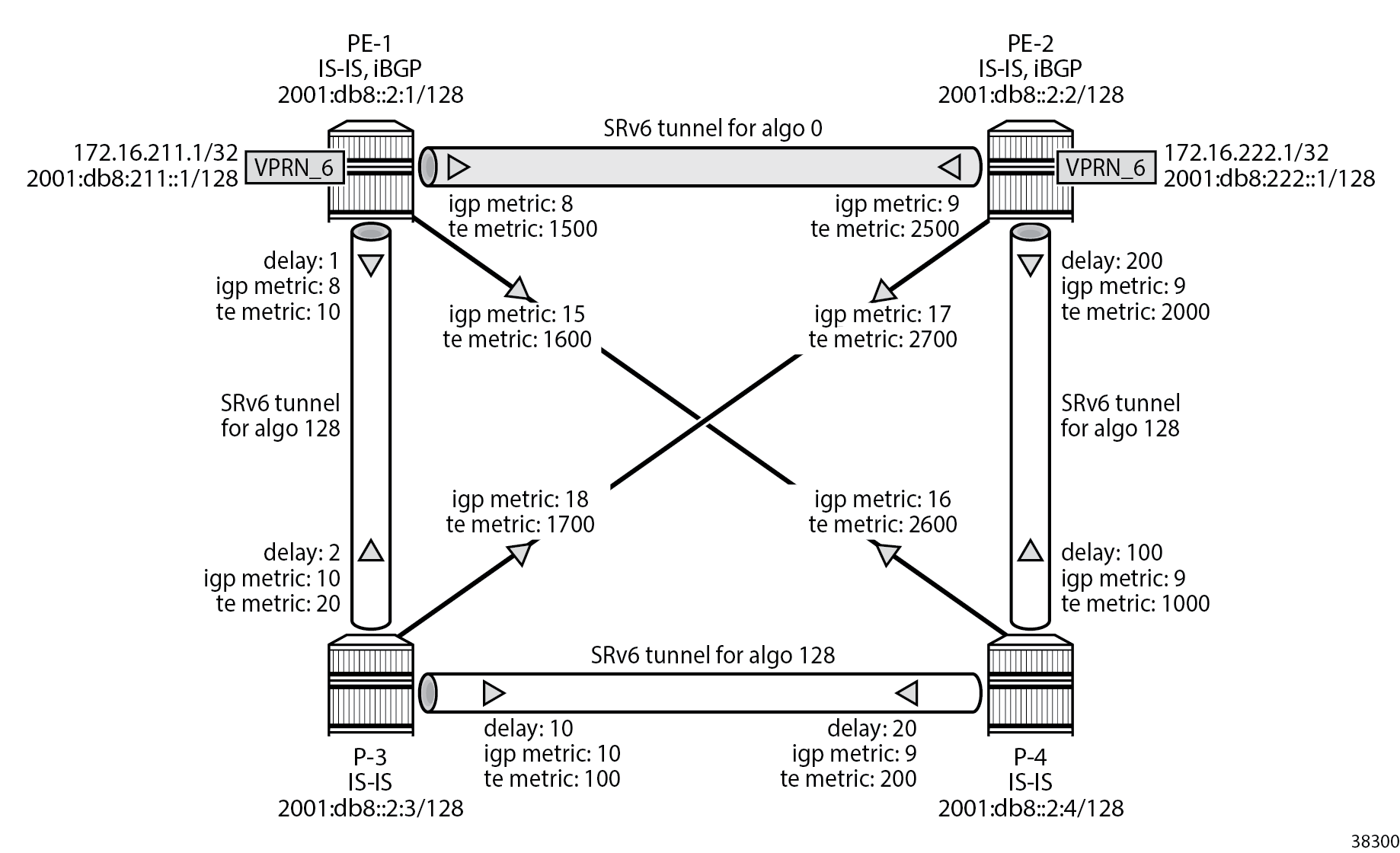
PE-1 and PE-2 are SRv6-enabled routers that each contain a VPRN instance. In this example, bidirectional IPv4 and IPv6 VPRN traffic flows are enabled between PE-1 and PE-2.
To illustrate what IS-IS interface metrics are used and how, the IS-IS interface metrics are configured explicitly (that is, differently from their default values), using the metric <ipv4-metric> command (for IPv4 unicast traffic) and the ipv6-unicast-metric <ipv6-metric> command (for IPv6 unicast traffic) in the router Base isis 0 interface <ip-int-name> level {1|2} context. Different values can be applied for IS-IS level 1 and IS-IS level 2; for each IS-IS level, a distinction can be made between IPv4 unicast traffic and IPv6 unicast traffic. For each IS-IS level and traffic type, different values can be configured in the two directions between two routers.
As a first example, the link delay metric is chosen for the Flex-Algorithm operation. The link delay metrics are configured explicitly, using the static <value> command (value in microseconds) in the router Base interface <interface-name> if-attribute delay context, only on the links between PE-1 and P-3, P-3 and P-4, and P-4 and PE-2. These metrics are configured differently in the two directions on each link (shown in the example topology as: "delay: <value in microseconds>"). The link delay metric can be configured on links between any pair of routers participating in the Flex-Algorithm instance. Any link that does not have the link delay metric configured is excluded from the Flex-Algorithm instance computation, which may result in no valid path between the ingress and egress routers. The link delay metric values are used for both IPv4 unicast traffic and IPv6 unicast traffic.
As a second example, the TE metric is chosen for the Flex-Algorithm operation. The TE metrics are configured explicitly, using the te-metric <value> command in the router Base mpls interface <interface-name> context, on all links. These metrics are configured differently in the two directions on each link, such that the direct link between the two routers PE-1 and PE-2 is always preferred.
The ping and traceroute commands between IPv4 and IPv6 loopback addresses in the VPRNs, as described in following sections, are used to simulate data traffic.
SRv6 requires wide metrics to match the 32-bit metric field in SRv6 locator TLV. The example configuration has wide metrics configured only for level 2. So, only the explicitly configured IS-IS level 2 interface metric values are used. Also, multi-topology and multi-protocol are not enabled in the example configuration. So, the explicitly configured IS-IS level 2 interface metric values are used for both IPv4 unicast traffic and IPv6 unicast traffic.
Configure the router
This configuration includes:
- ports and IPv6-only interfaces on PE-1, PE-2, P-3, and P-4, with link delay metrics configured where needed
- port cross-connect (PXC) on PE-1 and PE-2, using internal loopbacks on an FP4 MAC chip, as described in the "Segment Routing over IPv6" chapter in the Segment Routing and PCE volume of the 7450 ESS, 7750 SR, and 7950 XRS Advanced Configuration Guide - Part I
- IS-IS on PE-1, PE-2, P-3, and P-4, which includes:
- level 2 capability with wide metrics, and IPv4 metrics on all level 2 IS-IS interfaces
- native IPv6 routing
- the traffic-engineering and traffic-engineering-options commands, as a best practice to advertise the router capability within the autonomous system (AS)
- BGP on PE-1 and PE-2, with internal group "gr_v6_internal", which
includes:
- the IPv4 and IPv6 families
- extended-nh-encoding for IPv4
- advertise-ipv6-next-hops for IPv4
- BGP neighbor system IPv6 addresses
- next-hop-self
As the core network topology uses IPv6 for BGP peering (with IPv6 next hop addresses), the commands advertise-ipv6-next-hops and extended-nh-encoding need to be applied at the BGP, group, or neighbor level, so as to advertise and receive IPv4 routes with IPv6 next hop addresses. The advertise-ipv6-next-hops command instructs the system to advertise IPv4 routes with IPv6 next hop addresses. The extended-nh-encoding command configures BGP to advertise the capability to receive IPv4 routes with IPv6 next hop addresses.
The following example configuration applies for PE-1. A similar configuration applies for PE-2. P-3 and P-4 have no BGP configuration.
*A:PE-1# configure
    router Base
        autonomous-system 64500
        interface "int-PE-1-PE-2"
            description "interface between PE-1 and PE-2"
            port 1/1/c1/1:1000
            ipv6
                address 2001:db8::168:12:1/126
            exit
            no shutdown
        exit
        interface "int-PE-1-P-3"
            description "interface between PE-1 and P-3"
            port 1/1/c2/1:1000
            ipv6
                address 2001:db8::168:13:1/126
            exit
            if-attribute
                delay
                    static 1    # microseconds
                exit
            exit
            no shutdown
        exit
        interface "int-PE-1-P-4"
            description "interface between PE-1 and P-4"
            port 1/1/c3/1:1000
            ipv6
                address 2001:db8::168:14:1/126
            exit
            no shutdown
        exit
        interface "system"
            description "system interface of PE-1"
            ipv6
                address 2001:db8::2:1/128
            exit
            no shutdown
        exit
        isis 0
            router-id 1.1.1.1
            level-capability level-2
            area-id 49.0001
            traffic-engineering
            traffic-engineering-options
                ipv6
                application-link-attributes
                exit
            exit
            advertise-router-capability as
            ipv6-routing native
            level 2
                wide-metrics-only    # required for SRv6
            exit
            interface "system"
                passive
                no shutdown
            exit
            interface "int-PE-1-PE-2"
                interface-type point-to-point
                level 2
                    metric 8
                exit
                no shutdown
            exit
            interface "int-PE-1-P-3"
                interface-type point-to-point
                level 2
                    metric 8
                exit
                no shutdown
            exit
            interface "int-PE-1-P-4"
                interface-type point-to-point
                level 2
                    metric 15
                exit
                no shutdown
            exit
            no shutdown
        exit
        bgp
            min-route-advertisement 1
            router-id 1.1.1.10
            rapid-withdrawal
            split-horizon
            group "gr_v6_internal"
                description "internal bgp group on PE-1"
                family ipv4 ipv6
                next-hop-self
                type internal
                extended-nh-encoding ipv4
                advertise-ipv6-next-hops ipv4
                neighbor 2001:db8::2:2
                exit
            exit
            no shutdown
        exit
    exit all
Configure the VPRN services on PE-1 and on PE-2
This configuration includes:
- an IPv4 address and an IPv6 address for a loopback interface "lb_itf_vprn"
- BGP, with external group "gr_v6_vprn", which includes:
- IPv4 and IPv6 families
- extended-nh-encoding for IPv4
- advertise-ipv6-next-hops for IPv4
- BGP neighbor interface IPv6 addresses, with BGP neighbors in a different external AS
The following example configuration applies for the VPRN on PE-1. A similar configuration applies for the VPRN on PE-2.
*A:PE-1# configure service
        vprn 6 name "VPRN_6" customer 1 create
            description "VPRN_6 on PE-1"
            autonomous-system 64500
            interface "lb_itf_vprn" create
                address 172.16.211.1/32
                description "VPRN_6 interface on PE-1 for external subnet"
                ipv6
                    address 2001:db8:211::1/128
                exit
                loopback
            exit
            bgp
                group "gr_v6_vprn"
                    description "external bgp group for VPRN_6 on PE-1"
                    family ipv4 ipv6
                    extended-nh-encoding ipv4
                    advertise-ipv6-next-hops ipv4
                    neighbor 2001:db8:101::1
                        type external
                        peer-as 64501
                    exit
                exit
                no shutdown
            exit
            no shutdown
        exit all
Configure SRv6 in the router Base context on PE-1 and PE-2
Configure the SRv6 locator in the router Base segment-routing segment-routing-v6 context on PE-2. Perform a similar configuration on PE-1, with ip-prefix 2001:db8:aaaa:101::/64 for SRv6 locator "PE-1_loc".
*A:PE-2# configure router Base segment-routing segment-routing-v6
                locator "PE-2_loc"
                    block-length 48
                    function-length 20
                    no algorithm    # algo 0
                    prefix
                        ip-prefix 2001:db8:aaaa:102::/64
                    exit
                    no shutdown
                exit all
Configure the FPEs on PE-1 and PE-2.
*A:PE-2# configure
    fwd-path-ext
        fpe 1 create
            path pxc 1
            srv6 origination
                interface-a
                exit
                interface-b
                exit
            exit
        exit
        fpe 2 create
            path pxc 2
            srv6 termination
                interface-a
                exit
                interface-b
                exit
            exit
        exit
    exit all
Use FPE 1 as the SRv6 origination FPE in the router Base segment-routing segment-routing-v6 context and FPE 2 as the SRv6 termination FPE in the router Base segment-routing segment-routing-v6 locator <locator-name> context on PE-2. Perform a similar configuration on PE-1, for SRv6 locator "PE-1_loc". For more information, see the "Segment Routing over IPv6" chapter in the Segment Routing and PCE volume of the 7450 ESS, 7750 SR, and 7950 XRS Advanced Configuration Guide - Part I.
*A:PE-2# configure router Base segment-routing
            segment-routing-v6
                origination-fpe 1
                locator "PE-2_loc"
                    termination-fpe 2
                    no shutdown
                exit
            exit all
Configure the SRv6 End function (equivalent to an IPv4 node SID) in the router Base segment-routing segment-routing-v6 base-routing-instance locator <locator-name> context on PE-2. Perform a similar configuration on PE-1, for SRv6 locator "PE-1_loc".
*A:PE-2# configure router Base segment-routing segment-routing-v6 base-routing-instance
                    locator "PE-2_loc"
                        function
                            end 1
                                srh-mode usp
                            exit
                        exit
                    exit all
Advertise the SRv6 locator in IS-IS while ensuring level 2 capability on PE-2. Perform a similar configuration on PE-1, for SRv6 locator "PE-1_loc".
*A:PE-2# configure router Base isis 0
            segment-routing-v6
                locator "PE-2_loc"
                    level-capability level-2
                    level 2
                    exit
                exit
                no shutdown
            exit all
Configure SRv6 for the VPRNs on PE-1 and PE-2
On PE-1 and PE-2, extend the BGP advertisements to include the VPN-IPv4 and VPN-IPv6 families.
*A:PE-1#/*A:PE-2# configure router Base
        bgp
            rapid-update vpn-ipv4 vpn-ipv6
            group "gr_v6_internal"
                family ipv4 ipv6 vpn-ipv4 vpn-ipv6
                extended-nh-encoding ipv4 vpn-ipv4
                advertise-ipv6-next-hops ipv4 vpn-ipv4 vpn-ipv6
            exit
            no shutdown
        exit all
On PE-2, create an SRv6 instance for the VPRN service. Use the SRv6 locator from the router Base segment-routing segment-routing-v6 <instance> context and configure End.DT4 and End.DT6 functions for it.
Use the created SRv6 instance in the service vprn <service-id> bgp-ipvpn segment-routing-v6 context, with the configured SRv6 locator as the default locator. Ensure a unique route distinguisher. Use the unique PE-2 system IPv6 address as the source address. Perform a similar configuration on PE-1, with the PE-1 SRv6 locator as the default locator, the PE-1 system IPv6 address as the source address, and a different route distinguisher.
*A:PE-2# configure service
        vprn 6
            segment-routing-v6 1 create
                locator "PE-2_loc"
                    function
                        end-dt4
                        end-dt6
                    exit
                exit
            exit
            bgp-ipvpn
                segment-routing-v6
                    route-distinguisher 192.0.2.2:6
                    srv6-instance 1 default-locator "PE-2_loc"
                    source-address 2001:db8::2:2
                    vrf-target target:64506:6
                    no shutdown
                exit
            exit
            no shutdown
        exit all
Verify data traffic
At this point, using ping and traceroute commands, verify that IPv4 data traffic is possible between the local VPRN on PE-1 and the remote VPRN on PE-2:
*A:PE-1# ping router 6 172.16.222.1
PING 172.16.222.1 56 data bytes
64 bytes from 172.16.222.1: icmp_seq=1 ttl=64 time=1.49ms.
---snip---
---- 172.16.222.1 PING Statistics ----
5 packets transmitted, 5 packets received, 0.00% packet loss
round-trip min = 1.29ms, avg = 1.47ms, max = 1.65ms, stddev = 0.116ms

*A:PE-1# traceroute router 6 172.16.222.1
traceroute to 172.16.222.1, 30 hops max, 40 byte packets
  1  172.16.222.1 (172.16.222.1)    1.64 ms  1.71 ms  1.63 ms
This data traffic uses the SRv6 tunnels over the direct link between PE-1 and PE-2.
For IPv4 data traffic, the VPRN routing table shows the next hop and the applicable IGP metric for the route to 172.16.222.1.
*A:PE-1# show router 6 route-table 172.16.222.1

===============================================================================
Route Table (Service: 6)
===============================================================================
Dest Prefix[Flags]                            Type    Proto     Age        Pref
      Next Hop[Interface Name]                                    Metric
-------------------------------------------------------------------------------
172.16.222.1/32                               Remote  BGP VPN   00h01m52s  170
       2001:db8:aaaa:102:8000:: (tunneled:SRV6)                     8
-------------------------------------------------------------------------------
No. of Routes: 1
---snip---
===============================================================================
The next hop is the End.DT4 SRv6 SID of the SRv6 locator "PE-2_loc" for the VPRN on PE-2, which PE-1 learns from a BGP update from PE-2. The SRv6 tunnel to this next hop has label 524288.
*A:PE-2# show router segment-routing-v6 local-sid

===============================================================================
Segment Routing v6 Local SIDs
===============================================================================
SID                                               Type           Function
  Locator
  Context
-------------------------------------------------------------------------------
2001:db8:aaaa:102:0:1000::                        End            1
  PE-2_loc
  Base
2001:db8:aaaa:102:7fff:f000::                     End.DT6        524287
  PE-2_loc
  SvcId: 6 Name: VPRN_6
2001:db8:aaaa:102:8000::                          End.DT4        524288
  PE-2_loc
  SvcId: 6 Name: VPRN_6
-------------------------------------------------------------------------------
SIDs : 3
-------------------------------------------------------------------------------
===============================================================================
The applicable IGP metric is 8, which corresponds with the IS-IS level 2 "int-PE-1-PE-2" interface metric value.
*A:PE-1# show router isis 0 interface

===============================================================================
Rtr Base ISIS Instance 0 Interfaces
===============================================================================
Interface                        Level CircID  Oper      L1/L2 Metric     Type
                                               State
-------------------------------------------------------------------------------
system                           L1L2  1       Up        0/0              p2p
int-PE-1-PE-2                    L1L2  2       Up        6/8              p2p
int-PE-1-P-3                     L1L2  3       Up        6/8              p2p
int-PE-1-P-4                     L1L2  4       Up        11/15            p2p
-------------------------------------------------------------------------------
Interfaces : 4
===============================================================================
The show router isis 0 topology command lists the IS-IS nodes, and for each IS-IS node, the outgoing interface and the next hop. There are only IS-IS nodes at IS-IS level 2. The output of this command shows that data traffic from PE-1 to PE-2 uses interface "int-PE-1-PE-2" to PE-2, while, for example, data traffic from PE-1 to P-3 uses interface "int-PE-1-P-3" to P-3.
*A:PE-1# show router isis 0 topology

===============================================================================
Rtr Base ISIS Instance 0 Topology Table
===============================================================================
Node                                Interface                  Nexthop
-------------------------------------------------------------------------------
-------------------------------------------------------------------------------
IS-IS IP paths (MT-ID 0),   Level 2
-------------------------------------------------------------------------------
PE-2.00                             int-PE-1-PE-2              PE-2
P-3.00                              int-PE-1-P-3               P-3
P-4.00                              int-PE-1-P-4               P-4
===============================================================================
The show router isis 0 topology detail command lists the IS-IS nodes, and for each IS-IS node, the next hop, the outgoing interface, and the metric (in this case, IS-IS level 2) that applies.
*A:PE-1# show router isis 0 topology detail

===============================================================================
Rtr Base ISIS Instance 0 Topology Table
===============================================================================
-------------------------------------------------------------------------------
IS-IS IP paths (MT-ID 0),   Level 2
-------------------------------------------------------------------------------
Node      : PE-2.00
Nexthop   : PE-2
Interface : int-PE-1-PE-2
SNPA      : none                             Metric      : 8

Node      : P-3.00
Nexthop   : P-3
Interface : int-PE-1-P-3
SNPA      : none                             Metric      : 8

Node      : P-4.00
Nexthop   : P-4
Interface : int-PE-1-P-4
SNPA      : none                             Metric      : 15

===============================================================================
Verify the IS-IS data base on PE-1 with show router isis 0 database detail. The output of this command (shortened here for PE-1 and PE-2, and omitted for P-3 and P-4) provides information about each IS-IS-enabled router. For each uniquely identified IS-IS-enabled router, the SRv6 information indicates:
- the IS-IS-advertised router capabilities
- the IS-IS topology details
- the IPv4 and IPv6 reachability details
- the advertised SRv6 locator TLV
- the advertised configured SRv6 End SID
There is only IS-IS information at IS-IS level 2. On each IS-IS interface, the IS-IS level 2 metrics for IPv4 and IPv6 are identical.
Only the default metric-based SPF algorithm instance 0 is in use, as listed in the SR Alg sub-TLV of the Router Cap TLVs.
On PE-1 and PE-2, the SRv6 locator prefix for algorithm 0, with their End SRv6 SID are present.
*A:PE-1# show router isis 0 database detail

===============================================================================
Rtr Base ISIS Instance 0 Database (detail)
===============================================================================
---snip---
Displaying Level 2 database
-------------------------------------------------------------------------------
LSP ID    : PE-1.00-00                                  Level     : L2
---snip---
TLVs :
  Area Addresses:
    Area Address : (3) 49.0001
  Supp Protocols:
    Protocols     : IPv4
    Protocols     : IPv6
  IS-Hostname   : PE-1
  Router ID   :
    Router ID   : 1.1.1.1
  TE Router ID v6  :
    Router ID   : 2001:db8::2:1
  Router Cap : 1.1.1.1, D:0, S:0
    TE Node Cap : B E M  P
    SRv6 Cap: 0x0000
    SR Alg: metric based SPF
    Node MSD Cap: BMI : 0 SRH-MAX-SL : 10 SRH-MAX-END-POP : 9 SRH-MAX-H-ENCAPS : 3 SRH-MAX-END-D : 9
  I/F Addresses IPv6 :
    IPv6 Address    : 2001:db8::2:1
    IPv6 Address    : 2001:db8::168:12:1
    IPv6 Address    : 2001:db8::168:13:1
    IPv6 Address    : 2001:db8::168:14:1
  TE IS Nbrs   :
    Nbr   : PE-2.00
    Default Metric  : 8
    Sub TLV Len     : 36
    IPv6 Addr : 2001:db8::168:12:1
    Nbr IPv6  : 2001:db8::168:12:2
  TE IS Nbrs   :
    Nbr   : P-3.00
    Default Metric  : 8
    Sub TLV Len     : 36
    IPv6 Addr : 2001:db8::168:13:1
    Nbr IPv6  : 2001:db8::168:13:2
  TE IS Nbrs   :
    Nbr   : P-4.00
    Default Metric  : 15
    Sub TLV Len     : 36
    IPv6 Addr : 2001:db8::168:14:1
    Nbr IPv6  : 2001:db8::168:14:2
  IPv6 Reach:
    Metric: ( I ) 0
    Prefix   : 2001:db8::2:1/128
    Metric: ( I ) 8
    Prefix   : 2001:db8::168:12:0/126
    Metric: ( I ) 8
    Prefix   : 2001:db8::168:13:0/126
    Metric: ( I ) 15
    Prefix   : 2001:db8::168:14:0/126
    Metric: ( I ) 0
    Prefix   : 2001:db8:aaaa:101::/64
  SRv6 Locator  :
    MT ID : 0
    Metric: ( ) 0 Algo:0
    Prefix   : 2001:db8:aaaa:101::/64
    Sub TLV   :
      End-SID   : 2001:db8:aaaa:101:0:1000::, flags:0x0, endpoint:End-USP

-------------------------------------------------------------------------------
LSP ID    : PE-2.00-00                                  Level     : L2
---snip---
TLVs :
  Area Addresses:
    Area Address : (3) 49.0001
  Supp Protocols:
    Protocols     : IPv4
    Protocols     : IPv6
  IS-Hostname   : PE-2
  Router ID   :
    Router ID   : 2.2.2.2
  TE Router ID v6  :
    Router ID   : 2001:db8::2:2
  Router Cap : 2.2.2.2, D:0, S:0
    TE Node Cap : B E M  P
    SRv6 Cap: 0x0000
    SR Alg: metric based SPF
    Node MSD Cap: BMI : 0 SRH-MAX-SL : 10 SRH-MAX-END-POP : 9 SRH-MAX-H-ENCAPS : 3 SRH-MAX-END-D : 9
  ---snip---
  TE IS Nbrs   :
    Nbr   : PE-1.00
    Default Metric  : 9
    ---snip---
  TE IS Nbrs   :
    Nbr   : P-3.00
    Default Metric  : 17
    ---snip---
  TE IS Nbrs   :
    Nbr   : P-4.00
    Default Metric  : 9
    ---snip---
  ---snip---
  SRv6 Locator  :
    MT ID : 0
    Metric: ( ) 0 Algo:0
    Prefix   : 2001:db8:aaaa:102::/64
    Sub TLV   :
      End-SID   : 2001:db8:aaaa:102:0:1000::, flags:0x0, endpoint:End-USP
---snip---
Level (2) LSP Count : 4
-------------------------------------------------------------------------------
---snip---
SABM-flags Flags:  R = RSVP-TE
                   S = SR-TE
                   F = LFA
                   X = FLEX-ALGO
FAD-flags Flags:   M = Prefix Metric
===============================================================================
PE-2 advertises to PE-1 the information for network prefix 172.16.222.1/32, as listed in the RIB In Entries section in the following example. PE-1 acts in a similar way as PE-2 for network prefix 172.16.211.1/32, as listed in the RIB Out Entries section.
The following output shows the corresponding VPN-IPv4 BGP routes on PE-1:
*A:PE-1# show router bgp routes vpn-ipv4 hunt
===============================================================================
 BGP Router ID:1.1.1.10         AS:64500       Local AS:64500
===============================================================================
---snip---
===============================================================================
BGP VPN-IPv4 Routes
===============================================================================
-------------------------------------------------------------------------------
RIB In Entries
-------------------------------------------------------------------------------
Network        : 172.16.222.1/32
Nexthop        : 2001:db8::2:2
Route Dist.    : 192.0.2.2:6            VPN Label      : 524288
Path Id        : None
From           : 2001:db8::2:2
Res. Nexthop   : n/a
Local Pref.    : 100                    Interface Name : int-PE-1-PE-2
Aggregator AS  : None                   Aggregator     : None
Atomic Aggr.   : Not Atomic             MED            : None
AIGP Metric    : None                   IGP Cost       : 8
Connector      : None
Community      : target:64506:6
Cluster        : No Cluster Members
Originator Id  : None                   Peer Router Id : 2.2.2.10
Fwd Class      : None                   Priority       : None
Flags          : Used Valid Best IGP
---snip---
SRv6 TLV Type  : SRv6 L3 Service TLV (5)
SRv6 SubTLV    : SRv6 SID Information (1)
Sid            : 2001:db8:aaaa:102::
Full Sid       : 2001:db8:aaaa:102:8000::
Behavior       : End.DT4 (19)
SRv6 SubSubTLV : SRv6 SID Structure (1)
---snip---
VPRN Imported  :  6

-------------------------------------------------------------------------------
RIB Out Entries
-------------------------------------------------------------------------------
Network        : 172.16.211.1/32
Nexthop        : 2001:db8::2:1
Route Dist.    : 192.0.2.1:6            VPN Label      : 524288
Path Id        : None
To             : 2001:db8::2:2
Res. Nexthop   : n/a
Local Pref.    : 100                    Interface Name : NotAvailable
Aggregator AS  : None                   Aggregator     : None
Atomic Aggr.   : Not Atomic             MED            : None
AIGP Metric    : None                   IGP Cost       : n/a
Connector      : None
Community      : target:64506:6
Cluster        : No Cluster Members
Originator Id  : None                   Peer Router Id : 2.2.2.10
Origin         : IGP
---snip---
SRv6 TLV Type  : SRv6 L3 Service TLV (5)
SRv6 SubTLV    : SRv6 SID Information (1)
Sid            : 2001:db8:aaaa:101::
Full Sid       : 2001:db8:aaaa:101:8000::
Behavior       : End.DT4 (19)
SRv6 SubSubTLV : SRv6 SID Structure (1)
---snip---
-------------------------------------------------------------------------------
Routes : 2
===============================================================================
Verify the IPv6 route table on PE-1. The IPv6 route table has routes to the local and remote SRv6 locators and to the local SRv6 End function SID. The SRv6 locator prefix of PE-2 is reached via an SRv6 tunnel using IS-IS. The routes with protocol "SRV6" correspond with the locally configured SRv6 locator prefix of PE-1 and the locally configured SRv6 End function.
*A:PE-1# show router route-table ipv6

===============================================================================
IPv6 Route Table (Router: Base)
===============================================================================
Dest Prefix[Flags]                            Type    Proto     Age        Pref
      Next Hop[Interface Name]                                    Metric
-------------------------------------------------------------------------------
---snip---
2001:db8:aaaa:101::/64                        Local   SRV6      00h11m13s  3
       fe80::201-"_tmnx_fpe_2.a"                                    0
2001:db8:aaaa:101:0:1000::/128                Local   SRV6      00h11m13s  3
       Black Hole                                                   0
2001:db8:aaaa:102::/64                        Remote  ISIS      00h10m26s  18
       2001:db8:aaaa:102::/64 (tunneled:SRV6-ISIS)                  8
-------------------------------------------------------------------------------
No. of Routes: 13
---snip---
===============================================================================
Verify that the tunnel from PE-1 to the SRv6 locator prefix of PE-2 is an SRv6 tunnel that uses the "int-PE-1-PE-2" interface. A similar verification can be performed for the other direction. Interface "int-PE-1-PE-2" is configured on port 1/1/c1/1:1000.
*A:PE-1# show router fp-tunnel-table 1 ipv6

===============================================================================
IPv6 Tunnel Table Display
---snip---
===============================================================================
Destination                                  Protocol         Tunnel-ID
  Lbl/SID
    NextHop                                                   Intf/Tunnel
  Lbl/SID (backup)
    NextHop   (backup)
-------------------------------------------------------------------------------
2001:db8:aaaa:102::/64                       SRV6              524289
  -
    fe80::60e:1ff:fe01:1-"int-PE-1-PE-2"                     1/1/c1/1:1000
-------------------------------------------------------------------------------
Total Entries : 1
-------------------------------------------------------------------------------
===============================================================================
Verify also that IPv6 data traffic is possible between the local VPRN on PE-1 and the remote VPRN on PE-2:
*A:PE-1# ping router 6 2001:db8:222::1
PING 2001:db8:222::1 56 data bytes
64 bytes from 2001:db8:222::1 icmp_seq=1 hlim=64 time=1.84ms.
---snip---
---- 2001:db8:222::1 PING Statistics ----
5 packets transmitted, 5 packets received, 0.00% packet loss
round-trip min = 1.54ms, avg = 1.72ms, max = 1.84ms, stddev = 0.104ms

*A:PE-1# traceroute router 6 2001:db8:222::1
traceroute to 2001:db8:222::1, 30 hops max, 60 byte packets
  1  2001:db8:222::1 (2001:db8:222::1)    1.68 ms  1.84 ms  1.65 ms
For IPv6 data traffic, the VPRN routing table shows the next hop and the applicable IGP metric for the route to 2001:db8:222::1.
*A:PE-1# show router 6 route-table 2001:db8:222::1

===============================================================================
IPv6 Route Table (Service: 6)
===============================================================================
Dest Prefix[Flags]                            Type    Proto     Age        Pref
      Next Hop[Interface Name]                                    Metric
-------------------------------------------------------------------------------
2001:db8:222::1/128                           Remote  BGP VPN   00h01m52s  170
       2001:db8:aaaa:102:7fff:f000:: (tunneled:SRV6)                8
-------------------------------------------------------------------------------
No. of Routes: 1
---snip---
===============================================================================
The next hop is the End.DT6 SRv6 SID of the SRv6 locator "PE-2_loc" for the VPRN on PE-2, which PE-1 learns from a BGP update from PE-2. The SRv6 tunnel to this next hop has label 524287.
The applicable IGP metric is also 8, which again corresponds with the IS-IS level 2 "int-PE-1-PE-2" interface metric value.
PE-2 advertises to PE-1 the information for network prefix 2001:db8:222::1/128, as listed in the RIB In Entries section in the following example. PE-1 acts in a similar way as PE-2 for network prefix 2001:db8:211::1/128, as listed in the RIB Out Entries section.
The following output shows the corresponding VPN-IPv6 BGP routes on PE-1:
*A:PE-1# show router bgp routes vpn-ipv6 hunt
===============================================================================
 BGP Router ID:1.1.1.10         AS:64500       Local AS:64500
===============================================================================
---snip---
===============================================================================
BGP VPN-IPv6 Routes
===============================================================================
-------------------------------------------------------------------------------
RIB In Entries
-------------------------------------------------------------------------------
Network        : 2001:db8:222::1/128
Nexthop        : 2001:db8::2:2
Route Dist.    : 192.0.2.2:6            VPN Label      : 524287
Path Id        : None
From           : 2001:db8::2:2
Res. Nexthop   : n/a
Local Pref.    : 100                    Interface Name : int-PE-1-PE-2
Aggregator AS  : None                   Aggregator     : None
Atomic Aggr.   : Not Atomic             MED            : None
AIGP Metric    : None                   IGP Cost       : 8
Connector      : None
Community      : target:64506:6
Cluster        : No Cluster Members
Originator Id  : None                   Peer Router Id : 2.2.2.10
Fwd Class      : None                   Priority       : None
Flags          : Used Valid Best IGP
---snip---
SRv6 TLV Type  : SRv6 L3 Service TLV (5)
SRv6 SubTLV    : SRv6 SID Information (1)
Sid            : 2001:db8:aaaa:102::
Full Sid       : 2001:db8:aaaa:102:7fff:f000::
Behavior       : End.DT6 (18)
SRv6 SubSubTLV : SRv6 SID Structure (1)
---snip---
VPRN Imported  :  6

-------------------------------------------------------------------------------
RIB Out Entries
-------------------------------------------------------------------------------
Network        : 2001:db8:211::1/128
Nexthop        : 2001:db8::2:1
Route Dist.    : 192.0.2.1:6            VPN Label      : 524287
Path Id        : None
To             : 2001:db8::2:2
Res. Nexthop   : n/a
Local Pref.    : 100                    Interface Name : NotAvailable
Aggregator AS  : None                   Aggregator     : None
Atomic Aggr.   : Not Atomic             MED            : None
AIGP Metric    : None                   IGP Cost       : n/a
Connector      : None
Community      : target:64506:6
Cluster        : No Cluster Members
Originator Id  : None                   Peer Router Id : 2.2.2.10
Origin         : IGP
---snip---
SRv6 TLV Type  : SRv6 L3 Service TLV (5)
SRv6 SubTLV    : SRv6 SID Information (1)
Sid            : 2001:db8:aaaa:101::
Full Sid       : 2001:db8:aaaa:101:7fff:f000::
Behavior       : End.DT6 (18)
SRv6 SubSubTLV : SRv6 SID Structure (1)
---snip---
-------------------------------------------------------------------------------
Routes : 2
===============================================================================
Configure a delay-based flexible algorithm
Define a Flex-algorithm definition "FAD_delay" that takes delay as its metric. The FAD can reside on any IS-IS-enabled router. In this example, it resides on PE-1.
*A:PE-1# configure router Base
        flexible-algorithm-definitions
            flex-algo "FAD_delay" create
                description "FAD_delay_based"
                metric-type delay
                no shutdown
            exit
        exit all
Configure PE-1 so as to advertise the FAD "FAD_delay" in Flex-Algorithm instance 128 (possible values between 128 and 255) and to participate in the Flex-Algorithm instance 128.
*A:PE-1# configure router Base isis 0
            flexible-algorithms
                flex-algo 128
                    advertise "FAD_delay"
                    participate
                    exit
                exit
                no shutdown
            exit all
Ensure that the other IS-IS-enabled routers that must support the Flex-Algorithm instance participate in this Flex-Algorithm instance.
*A:PE-2#/*A:P-3#/*A:P-4# configure router Base isis 0
            flexible-algorithms
                flex-algo 128
                    participate
                    exit
                exit
                no shutdown
            exit all
Define a new and unique SRv6 locator prefix to this new Flex-Algorithm instance. A separate SRv6 locator is needed for each Flex-Algorithm instance. So, for the Flex-Algorithm instance 128, configure SRv6 locator "PE-2_loc_FAD128" on PE-2. Perform a similar configuration for SRv6 locator "PE-1_loc_FAD128" with ip-prefix 2001:db8:a128:101::/64 on PE-1.
*A:PE-2# configure router Base segment-routing segment-routing-v6
                locator "PE-2_loc_FAD128"
                    block-length 48
                    function-length 20
                    algorithm 128
                    prefix
                        ip-prefix 2001:db8:a128:102::/64
                    exit
                    no shutdown
                exit all
For SRv6 locator "PE-2_loc_FAD128" on PE-2, use FPE 2 as the SRv6 termination FPE in the router Base segment-routing segment-routing-v6 locator <locator-name> context and configure the SRv6 End function (equivalent to an IPv4 node SID) in the router Base segment-routing segment-routing-v6 base-routing-instance locator <locator-name> context. Perform a similar configuration on PE-1, for SRv6 locator "PE-1_loc_FAD128".
*A:PE-2# configure router Base segment-routing
            segment-routing-v6
                locator "PE-2_loc_FAD128"
                    termination-fpe 2
                    no shutdown
                exit
                base-routing-instance
                    locator "PE-2_loc_FAD128"
                        function
                            end 1
                                srh-mode usp
                            exit
                        exit
                    exit
                exit
            exit all
In the router Base isis 0 segment-routing-v6 locator <locator-name> context on PE-2, configure the IS-IS level capability for SRv6 locator "PE-2_loc_FAD128" and enable SRv6 in the IS-IS context. Perform a similar configuration on PE-1, for SRv6 locator "PE-1_loc_FAD128".
*A:PE-2# configure router Base isis 0
            segment-routing-v6
                locator "PE-2_loc_FAD128"
                    level-capability level-2
                    level 2
                    exit
                exit
                no shutdown
            exit all
*A:PE-2# show router isis 0 segment-routing-v6 locator

===============================================================================
Rtr Base ISIS Instance 0 SRv6 Locator Table
===============================================================================
Prefix                             AdvRtr                        MT     Lvl/Typ
 AttributeFlags                     Tag                           Flags  Algo
-------------------------------------------------------------------------------
2001:db8:a128:101::/64             PE-1                          0      2/Int.
  -                                  0                             -      128
2001:db8:a128:102::/64             PE-2                          0      2/Int.
  -                                  0                             -      128
2001:db8:aaaa:101::/64             PE-1                          0      2/Int.
  -                                  0                             -      0
2001:db8:aaaa:102::/64             PE-2                          0      2/Int.
  -                                  0                             -      0
-------------------------------------------------------------------------------
No. of Locators: 4
-------------------------------------------------------------------------------
---snip---
===============================================================================
On PE-2, in the service vprn segment-routing-v6 locator context, configure End.DT4 and End.DT6 functions for SRv6 locator "PE-2_loc_FAD128".
On PE-2, in the service vprn <service-id> bgp-ipvpn segment-routing-v6 context, use the SRv6 locator "PE-2_loc_FAD128" as the default locator, instead of the earlier SRv6 locator "PE-2_loc". The BGP IPVPN SRv6 instance for the VPRN must be shut down to allow this replacement. Perform a similar configuration on PE-1, for SRv6 locator "PE-1_loc_FAD128".
*A:PE-2# configure service
        vprn 6
            segment-routing-v6 1
                locator "PE-2_loc_FAD128"
                    function
                        end-dt4
                        end-dt6
                    exit
                exit
            exit
            bgp-ipvpn
                segment-routing-v6
                    shutdown
                    srv6-instance 1 default-locator "PE-2_loc_FAD128"
                    no shutdown
                exit
            exit
            no shutdown
        exit all
Verify data traffic
At this point, using ping and traceroute commands, verify that data traffic between the local VPRN on PE-1 and the remote VPRN on PE-2 uses the Flex-Algorithm.
For IPv4 data traffic:
*A:PE-1# ping router 6 172.16.222.1
PING 172.16.222.1 56 data bytes
64 bytes from 172.16.222.1: icmp_seq=1 ttl=64 time=2.47ms.
---snip---
---- 172.16.222.1 PING Statistics ----
5 packets transmitted, 5 packets received, 0.00% packet loss
round-trip min = 1.93ms, avg = 2.35ms, max = 2.51ms, stddev = 0.210ms

*A:PE-1# traceroute router 6 172.16.222.1
traceroute to 172.16.222.1, 30 hops max, 40 byte packets
  1  172.16.222.1 (172.16.222.1)    2.79 ms  2.43 ms  2.41 ms
For IPv6 data traffic:
*A:PE-1# ping router 6 2001:db8:222::1
PING 2001:db8:222::1 56 data bytes
64 bytes from 2001:db8:222::1 icmp_seq=1 hlim=64 time=2.31ms.
---snip---
---- 2001:db8:222::1 PING Statistics ----
5 packets transmitted, 5 packets received, 0.00% packet loss
round-trip min = 2.31ms, avg = 2.50ms, max = 2.71ms, stddev = 0.150ms

*A:PE-1# traceroute router 6 2001:db8:222::1
traceroute to 2001:db8:222::1, 30 hops max, 60 byte packets
  1  2001:db8:222::1 (2001:db8:222::1)    2.50 ms  2.48 ms  2.40 ms
This data traffic uses the SRv6 tunnels over the links between PE-1 and P-3, P-3 and P-4, and P-4 and PE-2.
For IPv4 data traffic, the VPRN routing table shows the next hop and the applicable metric for the route to 172.16.222.1. In this example, the End.DT4 SID is copied into the IPv6 DA field of the tunneled packet.
*A:PE-1# show router 6 route-table 172.16.222.1

===============================================================================
Route Table (Service: 6)
===============================================================================
Dest Prefix[Flags]                            Type    Proto     Age        Pref
      Next Hop[Interface Name]                                    Metric
-------------------------------------------------------------------------------
172.16.222.1/32                               Remote  BGP VPN   00h02m07s  170
       2001:db8:a128:102:7fff:e000:: (tunneled:SRV6)                111
-------------------------------------------------------------------------------
No. of Routes: 1
---snip---
===============================================================================
The tunnel next hop is the End.DT4 SRv6 SID of the SRv6 locator "PE-2_loc_FAD128" for the VPRN on PE-2, which PE-1 learns from a BGP update from PE-2. The SRv6 tunnel to this next hop has label 524286, which is the transposed SRv6 End.DT4 SID function value 0x7fffe.
*A:PE-2# show router segment-routing-v6 local-sid

===============================================================================
Segment Routing v6 Local SIDs
===============================================================================
SID                                               Type           Function
  Locator
  Context
-------------------------------------------------------------------------------
2001:db8:a128:102:0:1000::                        End            1
  PE-2_loc_FAD128
  Base
2001:db8:a128:102:7fff:d000::                     End.DT6        524285
  PE-2_loc_FAD128
  SvcId: 6 Name: VPRN_6
2001:db8:a128:102:7fff:e000::                     End.DT4        524286
  PE-2_loc_FAD128
  SvcId: 6 Name: VPRN_6
---snip---
-------------------------------------------------------------------------------
SIDs : 6
-------------------------------------------------------------------------------
===============================================================================
The show router isis 0 topology flex-algo 128 command lists the IS-IS nodes in the topology, and for each IS-IS node, the outgoing interface and the next hop. There are only IS-IS nodes at IS-IS level 2. The output of this command shows that data traffic from PE-1 to all IS-IS-enabled routers that participate in the Flex-Algorithm instance 128 (PE-2, P-3, and P-4) uses interface "int-PE-1-P-3" to P-3.
*A:PE-1# show router isis 0 topology flex-algo 128

===============================================================================
Rtr Base ISIS Instance 0 Flex-Algo 128 Topology Table
===============================================================================
Node                                Interface                  Nexthop
-------------------------------------------------------------------------------
-------------------------------------------------------------------------------
IS-IS IP paths (MT-ID 0),   Level 2
-------------------------------------------------------------------------------
PE-2.00                             int-PE-1-P-3               P-3
P-3.00                              int-PE-1-P-3               P-3
P-4.00                              int-PE-1-P-3               P-3
===============================================================================
The applicable metric is 111, which corresponds with the sum of the static link delays that are configured on the router interfaces "int-PE-1-P-3", "int-P-3-P-4", and "int-P-4-PE-2".
The show router isis 0 topology flex-algo 128 detail command lists the IS-IS nodes in the topology, and for each IS-IS node, the next hop, the outgoing interface, and the metric (in this case, link delay) that applies.
*A:PE-1# show router isis 0 topology flex-algo 128 detail

===============================================================================
Rtr Base ISIS Instance 0 Flex-Algo 128 Topology Table
===============================================================================
-------------------------------------------------------------------------------
IS-IS IP paths (MT-ID 0),   Level 2
-------------------------------------------------------------------------------
Node      : PE-2.00
Nexthop   : P-3
Interface : int-PE-1-P-3
SNPA      : none                             Metric      : 111

Node      : P-3.00
Nexthop   : P-3
Interface : int-PE-1-P-3
SNPA      : none                             Metric      : 1

Node      : P-4.00
Nexthop   : P-3
Interface : int-PE-1-P-3
SNPA      : none                             Metric      : 11

===============================================================================

*A:P-3# show router isis 0 topology flex-algo 128 detail

===============================================================================
Rtr Base ISIS Instance 0 Flex-Algo 128 Topology Table
===============================================================================
-------------------------------------------------------------------------------
IS-IS IP paths (MT-ID 0),   Level 2
-------------------------------------------------------------------------------
---snip---
Node      : PE-2.00
Nexthop   : P-4
Interface : int-P-3-P-4
SNPA      : none                             Metric      : 110

Node      : P-4.00
Nexthop   : P-4
Interface : int-P-3-P-4
SNPA      : none                             Metric      : 10

===============================================================================

*A:P-4# show router isis 0 topology flex-algo 128 detail

===============================================================================
Rtr Base ISIS Instance 0 Flex-Algo 128 Topology Table
===============================================================================
-------------------------------------------------------------------------------
IS-IS IP paths (MT-ID 0),   Level 2
-------------------------------------------------------------------------------
---snip---
Node      : PE-2.00
Nexthop   : PE-2
Interface : int-P-4-PE-2
SNPA      : none                             Metric      : 100
---snip---
===============================================================================
The IS-IS database on PE-1 contains more information, which relates to the use of the Flex-Algorithm.
There are additional link delay metrics (identical for IPv4 and IPv6) for each IS-IS-enabled router, as listed in the TE APP LINK ATTR sub-TLVs. The non-legacy Standard Application Bit Mask (SABM) flag value X indicates that they are associated with the Flex-Algorithm. Only the End SRv6 SIDs of the SRv6 locators are present.
Next to the default metric-based SPF, the Flex-Algorithm instance 128 is also in use, as listed in the SR Alg sub-TLV of the Router Cap TLVs.
The FAD sub-TLV of the PE-1 Router Cap TLV contains the delay-based definition for the Flex-Algorithm instance 128, which only router PE-1 advertises. The FAD flag value M indicates that the delay is a prefix metric.
On PE-1 and PE-2, next to the base SRv6 locator (for algorithm 0), with its End SRv6 SID, there is an additional SRv6 locator for the Flex-Algorithm instance 128, with its End SRv6 SID. This additional SRv6 locator indicates the prefix.
The show router isis 0 database detail command output on PE-1 is shown below, with separate entries for each IS-IS-enabled router.
For PE-1:
*A:PE-1# show router isis 0 database detail

===============================================================================
Rtr Base ISIS Instance 0 Database (detail)
===============================================================================
---snip---
Displaying Level 2 database
-------------------------------------------------------------------------------
LSP ID    : PE-1.00-00                                  Level     : L2
---snip---
TLVs :
  Area Addresses:
    Area Address : (3) 49.0001
  Supp Protocols:
    Protocols     : IPv4
    Protocols     : IPv6
  IS-Hostname   : PE-1
  Router ID   :
    Router ID   : 1.1.1.1
  TE Router ID v6  :
    Router ID   : 2001:db8::2:1
  Router Cap : 1.1.1.1, D:0, S:0
    TE Node Cap : B E M  P
    SRv6 Cap: 0x0000
    SR Alg: metric based SPF, 128
    Node MSD Cap: BMI : 0 SRH-MAX-SL : 10 SRH-MAX-END-POP : 9 SRH-MAX-H-ENCAPS : 3 SRH-MAX-END-D : 9
    FAD Sub-Tlv:
        Flex-Algorithm   : 128
        Metric-Type      : delay
        Calculation-Type : 0
        Priority         : 100
        Flags: M
  I/F Addresses IPv6 :
    IPv6 Address    : 2001:db8::2:1
    IPv6 Address    : 2001:db8::168:12:1
    IPv6 Address    : 2001:db8::168:13:1
    IPv6 Address    : 2001:db8::168:14:1
  TE IS Nbrs   :
    Nbr   : PE-2.00
    Default Metric  : 8
    Sub TLV Len     : 36
    IPv6 Addr : 2001:db8::168:12:1
    Nbr IPv6  : 2001:db8::168:12:2
  TE IS Nbrs   :
    Nbr   : P-3.00
    Default Metric  : 8
    Sub TLV Len     : 51
    IPv6 Addr : 2001:db8::168:13:1
    Nbr IPv6  : 2001:db8::168:13:2
    TE APP LINK ATTR    :
      SABML-flag:Non-Legacy SABM-flags:   X
        Delay Min : 1 Max : 1
  TE IS Nbrs   :
    Nbr   : P-4.00
    Default Metric  : 15
    Sub TLV Len     : 36
    IPv6 Addr : 2001:db8::168:14:1
    Nbr IPv6  : 2001:db8::168:14:2
  IPv6 Reach:
    Metric: ( I ) 0
    Prefix   : 2001:db8::2:1/128
    Metric: ( I ) 8
    Prefix   : 2001:db8::168:12:0/126
    Metric: ( I ) 8
    Prefix   : 2001:db8::168:13:0/126
    Metric: ( I ) 15
    Prefix   : 2001:db8::168:14:0/126
    Metric: ( I ) 0
    Prefix   : 2001:db8:aaaa:101::/64
  SRv6 Locator  :
    MT ID : 0
    Metric: ( ) 0 Algo:128
    Prefix   : 2001:db8:a128:101::/64
    Sub TLV   :
      End-SID   : 2001:db8:a128:101:0:1000::, flags:0x0, endpoint:End-USP
    Metric: ( ) 0 Algo:0
    Prefix   : 2001:db8:aaaa:101::/64
    Sub TLV   :
      End-SID   : 2001:db8:aaaa:101:0:1000::, flags:0x0, endpoint:End-USP
---snip---
Level (2) LSP Count : 4
-------------------------------------------------------------------------------
---snip---
SABM-flags Flags:  R = RSVP-TE
                   S = SR-TE
                   F = LFA
                   X = FLEX-ALGO
FAD-flags Flags:   M = Prefix Metric
===============================================================================
For PE-2:
*A:PE-1# show router isis 0 database detail

===============================================================================
Rtr Base ISIS Instance 0 Database (detail)
===============================================================================
---snip---
Displaying Level 2 database
-------------------------------------------------------------------------------
---snip---
LSP ID    : PE-2.00-00                                  Level     : L2
---snip---
TLVs :
  ---snip---
  Router Cap : 2.2.2.2, D:0, S:0
    TE Node Cap : B E M  P
    SRv6 Cap: 0x0000
    SR Alg: metric based SPF, 128
    Node MSD Cap: BMI : 0 SRH-MAX-SL : 10 SRH-MAX-END-POP : 9 SRH-MAX-H-ENCAPS : 3 SRH-MAX-END-D : 9
  ---snip---
  TE IS Nbrs   :
    Nbr   : PE-1.00
    Default Metric  : 9
    ---snip---
  TE IS Nbrs   :
    Nbr   : P-3.00
    Default Metric  : 17
    ---snip---
  TE IS Nbrs   :
    Nbr   : P-4.00
    Default Metric  : 9
    ---snip---
    TE APP LINK ATTR    :
      SABML-flag:Non-Legacy SABM-flags:   X
        Delay Min : 200 Max : 200
  ---snip---
  SRv6 Locator  :
    MT ID : 0
    Metric: ( ) 0 Algo:128
    Prefix   : 2001:db8:a128:102::/64
    Sub TLV   :
      End-SID   : 2001:db8:a128:102:0:1000::, flags:0x0, endpoint:End-USP
    Metric: ( ) 0 Algo:0
    Prefix   : 2001:db8:aaaa:102::/64
    Sub TLV   :
      End-SID   : 2001:db8:aaaa:102:0:1000::, flags:0x0, endpoint:End-USP
---snip---
===============================================================================
For P-3:
*A:PE-1# show router isis 0 database detail

===============================================================================
Rtr Base ISIS Instance 0 Database (detail)
===============================================================================
---snip---
Displaying Level 2 database
-------------------------------------------------------------------------------
---snip---
LSP ID    : P-3.00-00                                   Level     : L2
---snip---
TLVs :
  ---snip---
  Router Cap : 3.3.3.3, D:0, S:0
    TE Node Cap : B E M  P
    SRv6 Cap: 0x0000
    SR Alg: metric based SPF, 128
    Node MSD Cap: BMI : 0 SRH-MAX-SL : 10 SRH-MAX-END-POP : 9 SRH-MAX-H-ENCAPS : 3 SRH-MAX-END-D : 9
  ---snip---
  TE IS Nbrs   :
    Nbr   : PE-1.00
    Default Metric  : 10
    ---snip---
    TE APP LINK ATTR    :
      SABML-flag:Non-Legacy SABM-flags:   X
        Delay Min : 2 Max : 2
  TE IS Nbrs   :
    Nbr   : PE-2.00
    Default Metric  : 18
    ---snip---
  TE IS Nbrs   :
    Nbr   : P-4.00
    Default Metric  : 10
    ---snip---
    TE APP LINK ATTR    :
      SABML-flag:Non-Legacy SABM-flags:   X
        Delay Min : 10 Max : 10
  ---snip---
===============================================================================
For P-4:
*A:PE-1# show router isis 0 database detail

===============================================================================
Rtr Base ISIS Instance 0 Database (detail)
===============================================================================
---snip---
Displaying Level 2 database
-------------------------------------------------------------------------------
---snip---
LSP ID    : P-4.00-00                                   Level     : L2
---snip---
TLVs :
  ---snip---
  Router Cap : 4.4.4.4, D:0, S:0
    TE Node Cap : B E M  P
    SRv6 Cap: 0x0000
    SR Alg: metric based SPF, 128
    Node MSD Cap: BMI : 0 SRH-MAX-SL : 10 SRH-MAX-END-POP : 9 SRH-MAX-H-ENCAPS : 3 SRH-MAX-END-D : 9
  ---snip---
  TE IS Nbrs   :
    Nbr   : PE-1.00
    Default Metric  : 16
    ---snip---
  TE IS Nbrs   :
    Nbr   : PE-2.00
    Default Metric  : 9
    ---snip---
    TE APP LINK ATTR    :
      SABML-flag:Non-Legacy SABM-flags:   X
        Delay Min : 100 Max : 100
  TE IS Nbrs   :
    Nbr   : P-3.00
    Default Metric  : 9
    ---snip---
    TE APP LINK ATTR    :
      SABML-flag:Non-Legacy SABM-flags:   X
        Delay Min : 20 Max : 20
  ---snip---
===============================================================================
PE-2 advertises to PE-1 payload prefix 172.16.222.1/32, as listed in the RIB In Entries section in the following example. PE-1 computes the applicable metric 111, which corresponds with the sum of the link delays that are configured on the router interfaces "int-PE-1-P-3", "int-P-3-P-4", and "int-P-4-PE-2". PE-1 advertises to PE-2 payload prefix 172.16.211.1/32, as listed in the RIB Out Entries section in the following example. PE-2 computes the applicable metric 222, which corresponds with the sum of the link delays that are configured on the router interfaces "int-PE-2-P-4", "int-P-4-P-3", and "int-P-3-PE-1".
The following output shows the corresponding VPN-IPv4 BGP routes on PE-1:
*A:PE-1# show router bgp routes vpn-ipv4 hunt
===============================================================================
 BGP Router ID:1.1.1.10         AS:64500       Local AS:64500
===============================================================================
---snip---
===============================================================================
BGP VPN-IPv4 Routes
===============================================================================
-------------------------------------------------------------------------------
RIB In Entries
-------------------------------------------------------------------------------
Network        : 172.16.222.1/32
Nexthop        : 2001:db8::2:2
Route Dist.    : 192.0.2.2:6            VPN Label      : 524286
Path Id        : None
From           : 2001:db8::2:2
Res. Nexthop   : n/a
Local Pref.    : 100                    Interface Name : int-PE-1-PE-2
Aggregator AS  : None                   Aggregator     : None
Atomic Aggr.   : Not Atomic             MED            : None
AIGP Metric    : None                   IGP Cost       : 111
Connector      : None
Community      : target:64506:6
Cluster        : No Cluster Members
Originator Id  : None                   Peer Router Id : 2.2.2.10
Fwd Class      : None                   Priority       : None
Flags          : Used Valid Best IGP
---snip---
SRv6 TLV Type  : SRv6 L3 Service TLV (5)
SRv6 SubTLV    : SRv6 SID Information (1)
Sid            : 2001:db8:a128:102::
Full Sid       : 2001:db8:a128:102:7fff:e000::
Behavior       : End.DT4 (19)
SRv6 SubSubTLV : SRv6 SID Structure (1)
---snip---
VPRN Imported  :  6

-------------------------------------------------------------------------------
RIB Out Entries
-------------------------------------------------------------------------------
Network        : 172.16.211.1/32
Nexthop        : 2001:db8::2:1
Route Dist.    : 192.0.2.1:6            VPN Label      : 524286
Path Id        : None
To             : 2001:db8::2:2
Res. Nexthop   : n/a
Local Pref.    : 100                    Interface Name : NotAvailable
Aggregator AS  : None                   Aggregator     : None
Atomic Aggr.   : Not Atomic             MED            : None
AIGP Metric    : None                   IGP Cost       : n/a
Connector      : None
Community      : target:64506:6
Cluster        : No Cluster Members
Originator Id  : None                   Peer Router Id : 2.2.2.10
Origin         : IGP
---snip---
SRv6 TLV Type  : SRv6 L3 Service TLV (5)
SRv6 SubTLV    : SRv6 SID Information (1)
Sid            : 2001:db8:a128:101::
Full Sid       : 2001:db8:a128:101:7fff:e000::
Behavior       : End.DT4 (19)
SRv6 SubSubTLV : SRv6 SID Structure (1)
---snip---
-------------------------------------------------------------------------------
Routes : 2
===============================================================================
Verify the IPv6 route table on PE-1. The IPv6 route table has an additional route to the learned remote SRv6 locator for the Flex-Algorithm instance 128. This remotely configured SRv6 locator prefix of PE-2 is reached via an SRv6 tunnel.
*A:PE-1# show router route-table ipv6

===============================================================================
IPv6 Route Table (Router: Base)
===============================================================================
Dest Prefix[Flags]                            Type    Proto     Age        Pref
      Next Hop[Interface Name]                                    Metric
-------------------------------------------------------------------------------
---snip---
2001:db8:a128:101::/64                        Local   SRV6      00h02m30s  3
       fe80::201-"_tmnx_fpe_2.a"                                    0
2001:db8:a128:101:0:1000::/128                Local   SRV6      00h02m30s  3
       Black Hole                                                   0
2001:db8:a128:102::/64                        Remote  ISIS      00h01m55s  18
       2001:db8:a128:102::/64 (tunneled:SRV6-ISIS)                  111
2001:db8:aaaa:101::/64                        Local   SRV6      00h18m00s  3
       fe80::201-"_tmnx_fpe_2.a"                                    0
2001:db8:aaaa:101:0:1000::/128                Local   SRV6      00h18m00s  3
       Black Hole                                                   0
2001:db8:aaaa:102::/64                        Remote  ISIS      00h17m13s  18
       2001:db8:aaaa:102::/64 (tunneled:SRV6-ISIS)                  8
-------------------------------------------------------------------------------
No. of Routes: 16
---snip---
===============================================================================
Verify that the tunnel from PE-1 to the remote locator is an SRv6 tunnel that uses the "int-PE-1-P-3" interface. Perform a similar verification for the tunnel from PE-2, where the SRv6 tunnel to the remote locator uses the "int-PE-2-P-4" interface. Interface "int-PE-1-P-3" is configured on port 1/1/c2/1:1000.
*A:PE-1# show router fp-tunnel-table 1 ipv6

===============================================================================
IPv6 Tunnel Table Display
---snip---
===============================================================================
Destination                                  Protocol         Tunnel-ID
  Lbl/SID
    NextHop                                                   Intf/Tunnel
  Lbl/SID (backup)
    NextHop   (backup)
-------------------------------------------------------------------------------
2001:db8:a128:102::/64                       SRV6              524290
  -
    fe80::612:1ff:fe01:b-"int-PE-1-P-3"                      1/1/c2/1:1000
2001:db8:aaaa:102::/64                       SRV6              524289
  -
    fe80::60e:1ff:fe01:1-"int-PE-1-PE-2"                     1/1/c1/1:1000
-------------------------------------------------------------------------------
Total Entries : 2
-------------------------------------------------------------------------------
===============================================================================
For IPv6 data traffic, the VPRN routing table shows the next hop and the applicable metric for the route to 2001:db8:222::1.
*A:PE-1# show router 6 route-table 2001:db8:222::1

===============================================================================
IPv6 Route Table (Service: 6)
===============================================================================
Dest Prefix[Flags]                            Type    Proto     Age        Pref
      Next Hop[Interface Name]                                    Metric
-------------------------------------------------------------------------------
2001:db8:222::1/128                           Remote  BGP VPN   00h02m07s  170
       2001:db8:a128:102:7fff:d000:: (tunneled:SRV6)                111
-------------------------------------------------------------------------------
No. of Routes: 1
---snip---
===============================================================================
The next hop is the End.DT6 SRv6 SID of the SRv6 locator "PE-2_loc_FAD128" for the VPRN on PE-2, which PE-1 learns from a BGP update from PE-2. The SRv6 tunnel to this next hop has label 524285.
The applicable metric is also 111, which again corresponds with the sum of the link delays that are configured on the router interfaces "int-PE-1-P-3", "int-P-3-P-4", and "int-P-4-PE-2".
PE-2 advertises to PE-1 the information for network prefix 2001:db8:222::1/128, as listed in the RIB In Entries section in the following example. PE-1 computes the applicable metric 111, which corresponds with the sum of the link delays that are configured on the router interfaces "int-PE-1-P-3", "int-P-3-P-4", and "int-P-4-PE-2". PE-1 advertises to PE-2 payload prefix 2001:db8:211::1/128, as listed in the RIB Out Entries section in the following example. PE-2 computes the applicable metric 222, which corresponds with the sum of the link delays that are configured on the router interfaces "int-PE-2-P-4", "int-P-4-P-3", and "int-P-3-PE-1".
The following output shows the corresponding VPN-IPv6 BGP routes on PE-1:
*A:PE-1# show router bgp routes vpn-ipv6 hunt
===============================================================================
 BGP Router ID:1.1.1.10         AS:64500       Local AS:64500
===============================================================================
---snip---
===============================================================================
BGP VPN-IPv6 Routes
===============================================================================
-------------------------------------------------------------------------------
RIB In Entries
-------------------------------------------------------------------------------
Network        : 2001:db8:222::1/128
Nexthop        : 2001:db8::2:2
Route Dist.    : 192.0.2.2:6            VPN Label      : 524285
Path Id        : None
From           : 2001:db8::2:2
Res. Nexthop   : n/a
Local Pref.    : 100                    Interface Name : int-PE-1-PE-2
Aggregator AS  : None                   Aggregator     : None
Atomic Aggr.   : Not Atomic             MED            : None
AIGP Metric    : None                   IGP Cost       : 111
Connector      : None
Community      : target:64506:6
Cluster        : No Cluster Members
Originator Id  : None                   Peer Router Id : 2.2.2.10
Fwd Class      : None                   Priority       : None
Flags          : Used Valid Best IGP
---snip---
SRv6 TLV Type  : SRv6 L3 Service TLV (5)
SRv6 SubTLV    : SRv6 SID Information (1)
Sid            : 2001:db8:a128:102::
Full Sid       : 2001:db8:a128:102:7fff:d000::
Behavior       : End.DT6 (18)
SRv6 SubSubTLV : SRv6 SID Structure (1)
---snip---
VPRN Imported  :  6

-------------------------------------------------------------------------------
RIB Out Entries
-------------------------------------------------------------------------------
Network        : 2001:db8:211::1/128
Nexthop        : 2001:db8::2:1
Route Dist.    : 192.0.2.1:6            VPN Label      : 524285
Path Id        : None
To             : 2001:db8::2:2
Res. Nexthop   : n/a
Local Pref.    : 100                    Interface Name : NotAvailable
Aggregator AS  : None                   Aggregator     : None
Atomic Aggr.   : Not Atomic             MED            : None
AIGP Metric    : None                   IGP Cost       : n/a
Connector      : None
Community      : target:64506:6
Cluster        : No Cluster Members
Originator Id  : None                   Peer Router Id : 2.2.2.10
Origin         : IGP
---snip---
SRv6 TLV Type  : SRv6 L3 Service TLV (5)
SRv6 SubTLV    : SRv6 SID Information (1)
Sid            : 2001:db8:a128:101::
Full Sid       : 2001:db8:a128:101:7fff:d000::
Behavior       : End.DT6 (18)
SRv6 SubSubTLV : SRv6 SID Structure (1)
---snip---
-------------------------------------------------------------------------------
Routes : 2
===============================================================================
Configure TE metrics on the router interfaces
For example for PE-1. A similar configuration applies for the other routers.
*A:PE-1# configure
    router Base
        mpls
            interface "int-PE-1-PE-2"
                te-metric 1500
                no shutdown
            exit
            interface "int-PE-1-P-3"
                te-metric 10
                no shutdown
            exit
            interface "int-PE-1-P-4"
                te-metric 1600
                no shutdown
            exit
            no shutdown
        exit
        rsvp
            no shutdown
        exit
    exit all
Configure a TE-metric-based flexible algorithm
Define a Flex-Algorithm definition "FAD_te_metric" that uses TE metric metric type. The FAD can reside on any IS-IS-enabled router. In this example, it resides on PE-1.
*A:PE-1# configure router Base flexible-algorithm-definitions # strictly needed on only 1 router in ISIS level
            flex-algo "FAD_te_metric" create
                description "FAD_te_metric_based"
                metric-type te-metric
            exit all
Configure PE-1 so as to advertise the FAD "FAD_te_metric" in Flex-Algorithm instance 128 and to participate in the Flex-Algorithm instance 128.
*A:PE-1# configure router Base isis 0
            flexible-algorithms
                flex-algo 128
                    advertise "FAD_te_metric"
                    participate
                    exit
                exit
                no shutdown
            exit all
Ensure that the other IS-IS-enabled routers that must support the Flex-Algorithm instance participate in this Flex-Algorithm instance.
*A:PE-2#/*A:P-3#/*A:P-4# configure router Base isis 0
            flexible-algorithms
                flex-algo 128
                    participate
                    exit
                exit
                no shutdown
            exit all
Verify data traffic
At this point, using ping and traceroute commands, verify that data traffic between the local VPRN on PE-1 and the remote VPRN on PE-2 uses the modified Flex-Algorithm.
For IPv4 data traffic:
*A:PE-1# ping router 6 172.16.222.1
PING 172.16.222.1 56 data bytes
64 bytes from 172.16.222.1: icmp_seq=1 ttl=64 time=2.77ms.
---snip---
---- 172.16.222.1 PING Statistics ----
5 packets transmitted, 5 packets received, 0.00% packet loss
round-trip min = 1.86ms, avg = 2.44ms, max = 2.77ms, stddev = 0.329ms

*A:PE-1# traceroute router 6 172.16.222.1
traceroute to 172.16.222.1, 30 hops max, 40 byte packets
  1  172.16.222.1 (172.16.222.1)    3.09 ms  3.08 ms  2.33 ms
For IPv6 data traffic:
*A:PE-1# ping router 6 2001:db8:222::1
PING 2001:db8:222::1 56 data bytes
64 bytes from 2001:db8:222::1 icmp_seq=1 hlim=64 time=2.53ms.
---snip---
---- 2001:db8:222::1 PING Statistics ----
5 packets transmitted, 5 packets received, 0.00% packet loss
round-trip min = 1.88ms, avg = 2.31ms, max = 2.86ms, stddev = 0.356ms

*A:PE-1# traceroute router 6 2001:db8:222::1
traceroute to 2001:db8:222::1, 30 hops max, 60 byte packets
  1  2001:db8:222::1 (2001:db8:222::1)    2.74 ms  2.40 ms  2.64 ms
- the metric type changes to te-metric (from delay)
- the TE APP LINK ATTR sub-TLVs contain a TE Metric value
- the applicable metric for the route between the local VPRN on PE-1 and
the remote VPRN on PE-2 changes to 1110 (from 111 microseconds),
corresponding with the sum of the metric values along the path PE-1,
P-3, P-4, PE-2, as shown in the following show router isis 0
topology flex-algo 128 detail command output
examples.
On PE-1:
*A:PE-1# show router isis 0 topology flex-algo 128 detail

===============================================================================
Rtr Base ISIS Instance 0 Flex-Algo 128 Topology Table
===============================================================================
-------------------------------------------------------------------------------
IS-IS IP paths (MT-ID 0),   Level 2
-------------------------------------------------------------------------------
Node      : PE-2.00
Nexthop   : P-3
Interface : int-PE-1-P-3
SNPA      : none                             Metric      : 1110

Node      : P-3.00
Nexthop   : P-3
Interface : int-PE-1-P-3
SNPA      : none                             Metric      : 10

Node      : P-4.00
Nexthop   : P-3
Interface : int-PE-1-P-3
SNPA      : none                             Metric      : 110

===============================================================================
On P-3:
*A:P-3# show router isis 0 topology flex-algo 128 detail

===============================================================================
Rtr Base ISIS Instance 0 Flex-Algo 128 Topology Table
===============================================================================
-------------------------------------------------------------------------------
IS-IS IP paths (MT-ID 0),   Level 2
-------------------------------------------------------------------------------
---snip---
Node      : PE-2.00
Nexthop   : P-4
Interface : int-P-3-P-4
SNPA      : none                             Metric      : 1100

Node      : P-4.00
Nexthop   : P-4
Interface : int-P-3-P-4
SNPA      : none                             Metric      : 100

===============================================================================
On P-4:
*A:P-4# show router isis 0 topology flex-algo 128 detail

===============================================================================
Rtr Base ISIS Instance 0 Flex-Algo 128 Topology Table
===============================================================================
-------------------------------------------------------------------------------
IS-IS IP paths (MT-ID 0),   Level 2
-------------------------------------------------------------------------------
---snip---
Node      : PE-2.00
Nexthop   : PE-2
Interface : int-P-4-PE-2
SNPA      : none                             Metric      : 1000
---snip---
===============================================================================
Conclusion
The Flex-Algorithm for SRv6-based VPRNs feature allows the computation of constraint-based paths across an SRv6-enabled network, based on metrics other than the default IGP metrics. This allows carrying data traffic over an end-to-end path that is optimized using the best suited metric IGP, delay, or TE).