Multi-Chassis Endpoint for VPLS Active/Standby Pseudowire
This chapter provides information about multi-chassis endpoint for VPLS active/standby pseudowire.
Topics in this chapter include:
Applicability
This chapter was initially written for SR OS Release 7.0.R6, but the CLI in this edition is based on SR OS Release 23.7.R2.
Overview
When implementing a large VPLS, one of the limiting factors is the number of T-LDP sessions required for the full mesh of SDPs. Mesh-SDPs are required between all PEs participating in the VPLS with a full mesh of T-LDP sessions.
This solution is not scalable, because the number of sessions grows more rapidly than the number of participating PEs. Several options exist to reduce the number of T-LDP sessions required in a large VPLS.
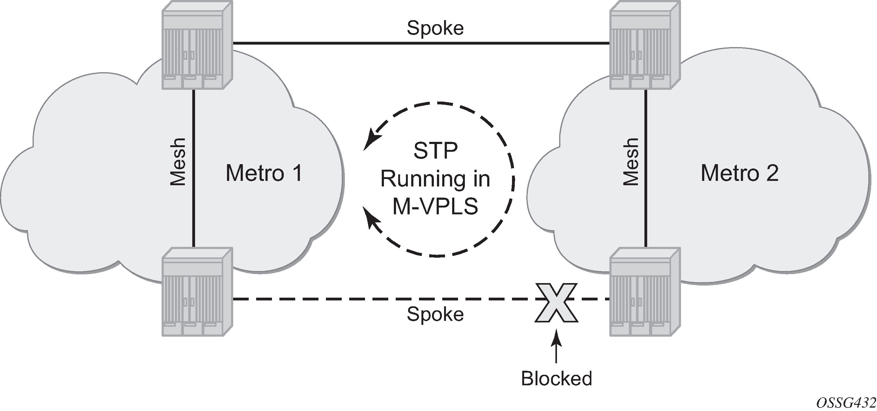
The first option is hierarchical VPLS (H-VPLS) with spoke SDPs. By using spoke SDPs between two clouds of fully meshed PEs, any-to-any T-LDP sessions for all participating PEs are not required.
However, if spoke SDP redundancy is required, STP must be used to avoid a loop in the VPLS. Management VPLS can be used to reduce the number of STP instances and separate customer and STP traffic, as illustrated in H-VPLS with STP.
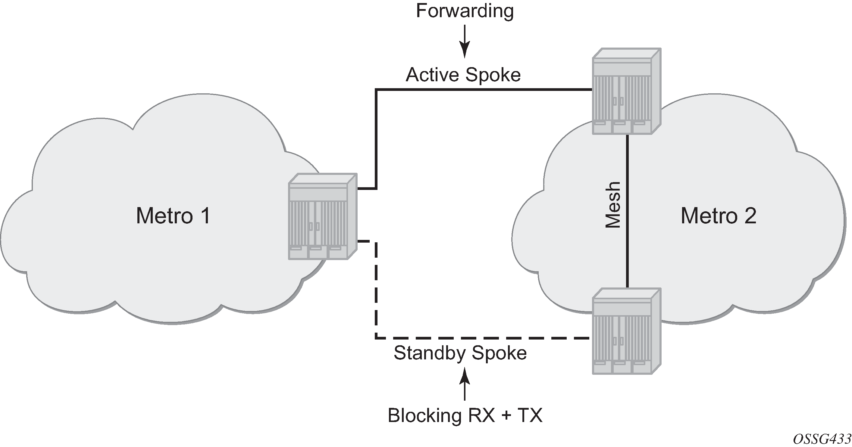
VPLS pseudowire redundancy provides H-VPLS redundant spoke connectivity. The active spoke SDP is in forwarding state, while the standby spoke SDP is in blocking state. Therefore, STP is not needed anymore to break the loop, as illustrated in VPLS pseudowire redundancy.
However, the PE implementing the active and standby spokes represents a single point of failure in the network.
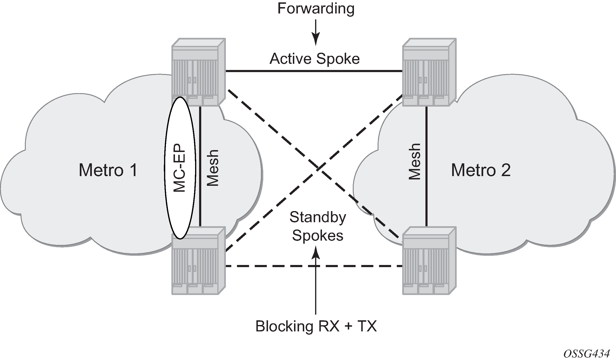
Multi-chassis endpoint (MC-EP) for VPLS active/standby pseudowire expands on the VPLS pseudowire redundancy and allows the removal of the single point of failure.
Only one spoke SDP is in forwarding state; all standby spoke SDPs are in blocking state. Mesh and square resiliency are supported.
Mesh resiliency can protect against simultaneous node failure in the core and in the MC-EP (double failure), but requires more SDPs (and therefore more T-LDP sessions). Mesh resiliency is illustrated in Multi-chassis endpoint with mesh resiliency.
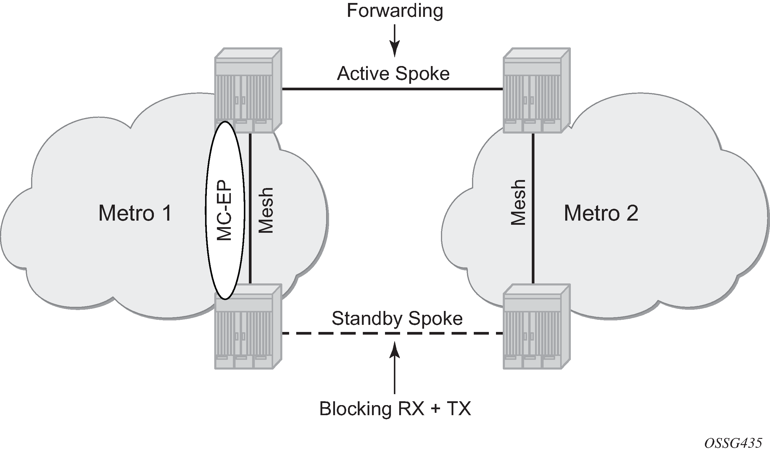
Square resiliency provides single failure node protection, and requires less SDPs (and thus less T-LDP sessions). Square resiliency is illustrated in Multi-chassis endpoint with square resiliency.
Example topology
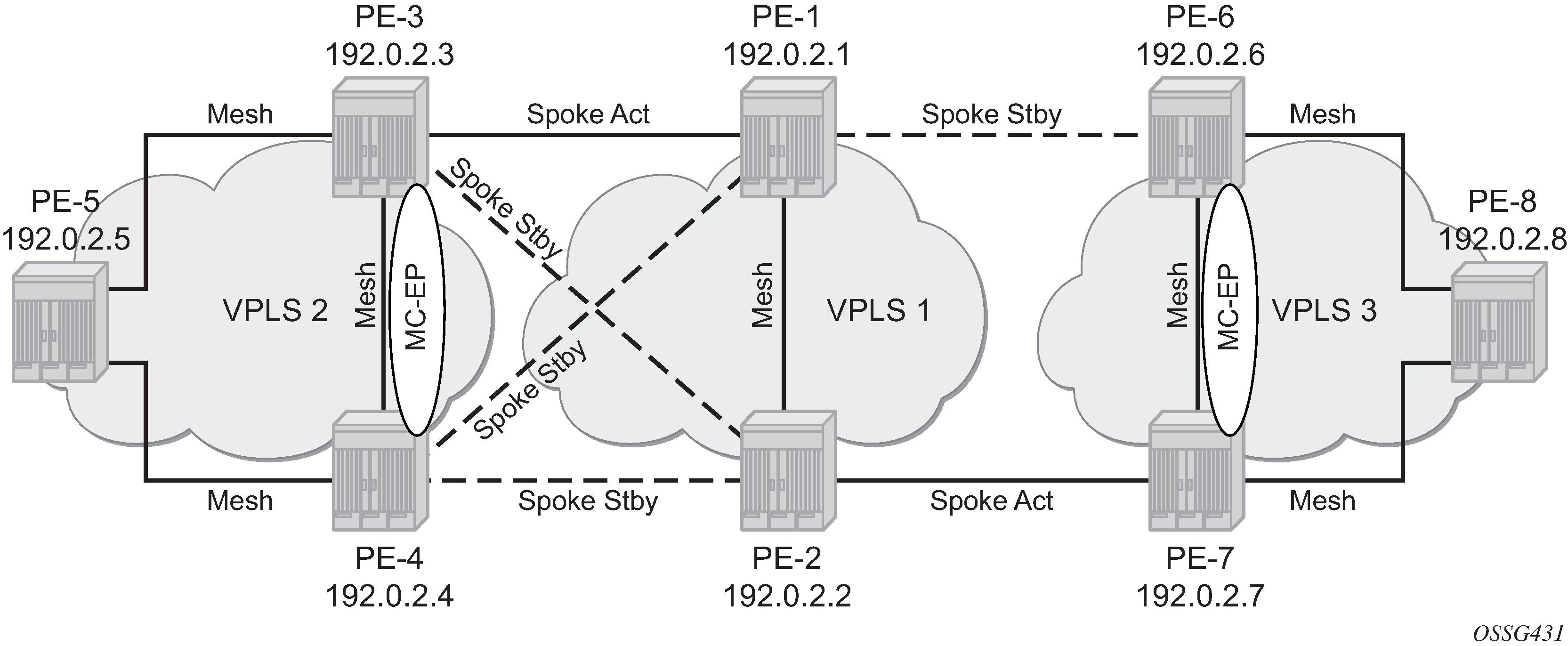
The network topology is displayed in Example topology.
The setup consists of:
Two core nodes (PE-1 and PE-2), and three nodes for each metro area (PE-3, PE-4, PE-5 and PE-6, PE-7, PE-8, respectively).
VPLS "Core VPLS-1" is the core VPLS, used to interconnect the two metro areas represented by VPLSs "Metro 1 VPLS-2" and "Metro 2 VPLS-3".
VPLS "Metro 1 VPLS-2" is connected to the VPLS "Core VPLS-1" in mesh resiliency.
VPLS "Metro 2 VPLS-3" is connected to the VPLS "Core VPLS-1" in square resiliency.
Three separate VPLS identifiers are used for clarity. However, the same identifier could be used for each. For interoperation, only the same VC-ID is required to be used on both ends of the spoke SDPs.
The initial configuration includes:
Cards, MDAs, ports, router interfaces
-
IS-IS on all router interfaces (alternatively, OSPF can be configured)
LDP on all router interfaces (alternatively, RSVP-signaled LSPs can be configured over the paths used for mesh/spoke SDPs)
Configuration
SDP configuration
On each PE, SDPs are created to match the topology described in Example topology.
The convention for the SDP naming is: XY where X is the originating node and Y the target node.
The SDP configuration in PE-3 is as follows:
# on PE-3:
configure
    service
        sdp 31 mpls create
            far-end 192.0.2.1
            ldp
            no shutdown
        exit
        sdp 32 mpls create
            far-end 192.0.2.2
            ldp
            no shutdown
        exit
        sdp 34 mpls create
            far-end 192.0.2.4
            ldp
            no shutdown
        exit
        sdp 35 mpls create
            far-end 192.0.2.5
            ldp
            no shutdown
        exit
The following command shows that the SDPs on PE-3 are operationally up:
*A:PE-3# show service sdp

============================================================================
Services: Service Destination Points
============================================================================
SdpId  AdmMTU  OprMTU  Far End          Adm  Opr         Del     LSP   Sig
----------------------------------------------------------------------------
31     0       8914    192.0.2.1        Up   Up          MPLS    L     TLDP
32     0       8914    192.0.2.2        Up   Up          MPLS    L     TLDP
34     0       8914    192.0.2.4        Up   Up          MPLS    L     TLDP
35     0       8914    192.0.2.5        Up   Up          MPLS    L     TLDP
----------------------------------------------------------------------------
Number of SDPs : 4
----------------------------------------------------------------------------
Legend: R = RSVP, L = LDP, B = BGP, M = MPLS-TP, n/a = Not Applicable
        I = SR-ISIS, O = SR-OSPF, T = SR-TE, F = FPE
============================================================================
Full mesh VPLS configuration
Three fully meshed VPLS services are configured:
VPLS "Core VPLS-1" on PE-1 and PE-2
VPLS "Metro 1 VPLS-2" on PE-3, PE-4, and PE-5
VPLS "Metro 2 VPLS-3" on PE-6, PE-7, and PE-8
VPLS "Core VPLS-1" is configured on PE-1 as follows. The configuration on PE-2 is similar.
# on PE-1:
configure
    service
        vpls 1 name "Core VPLS-1" customer 1 create
            description "core VPLS"
            mesh-sdp 12:1 create
            exit
            no shutdown
        exit
VPLS "Metro 1 VPLS-2" is configured on PE-3 as follows. The configuration on PE-4 and PE-5 is similar.
# on PE-3:
configure
    service
        vpls 2 name "Metro 1 VPLS-2" customer 1 create
            description "Metro 1 VPLS"
            mesh-sdp 34:2 create
            exit
            mesh-sdp 35:2 create
            exit
            no shutdown
        exit
VPLS "Metro 2 VPLS-3" is configured on PE-6 as follows. The configuration on PE-7 and PE-8 is similar.
# on PE-6:
configure
    service
        vpls 3 name "Metro 2 VPLS-3" customer 1 create
            description "Metro 2 VPLS"
            mesh-sdp 67:3 create
            exit
            mesh-sdp 68:3 create
            exit
            no shutdown
        exit
Verification of the VPLS:
The service must be operationally up.
All mesh SDPs must be up in the VPLS service.
On PE-6 (similar on other nodes):
*A:PE-6# show service id 3 base

===============================================================================
Service Basic Information
===============================================================================
Service Id        : 3                   Vpn Id            : 0
Service Type      : VPLS
MACSec enabled    : no
Name              : Metro 2 VPLS-3
Description       : Metro 2 VPLS
Customer Id       : 1                   Creation Origin   : manual
Last Status Change: 10/03/2023 06:11:15
Last Mgmt Change  : 10/03/2023 06:11:09
Etree Mode        : Disabled
Admin State       : Up                  Oper State        : Up
MTU               : 1514
SAP Count         : 0                   SDP Bind Count    : 2
Snd Flush on Fail : Disabled            Host Conn Verify  : Disabled
SHCV pol IPv4     : None
Propagate MacFlush: Disabled            Per Svc Hashing   : Disabled
Allow IP Intf Bind: Disabled
Fwd-IPv4-Mcast-To*: Disabled            Fwd-IPv6-Mcast-To*: Disabled
Mcast IPv6 scope  : mac-based
Def. Gateway IP   : None
Def. Gateway MAC  : None
Temp Flood Time   : Disabled            Temp Flood        : Inactive
Temp Flood Chg Cnt: 0
SPI load-balance  : Disabled
TEID load-balance : Disabled
Lbl Eth/IP L4 TEID: Disabled
Src Tep IP        : N/A
Vxlan ECMP        : Disabled
MPLS ECMP         : Disabled
Ignore MTU Mismat*: Disabled
Tunnel ELMI       : Disabled

-------------------------------------------------------------------------------
Service Access & Destination Points
-------------------------------------------------------------------------------
Identifier                               Type         AdmMTU  OprMTU  Adm  Opr
-------------------------------------------------------------------------------
sdp:67:3 M(192.0.2.7)                    Mesh         0       8914    Up   Up
sdp:68:3 M(192.0.2.8)                    Mesh         0       8914    Up   Up
===============================================================================
* indicates that the corresponding row element may have been truncated.
Multi-chassis configuration
Multi-chassis is configured on the MC peers PE-3, PE-4 and PE-6, PE-7. The peer system address is configured, and mc-endpoint is enabled.
The multi-chassis configuration on PE-3 is as follows. The configuration on PE-4, PE-6, and PE-7 is similar.
# on PE-3:
configure
    redundancy
        multi-chassis
            peer 192.0.2.4 create
                mc-endpoint
                    no shutdown
                exit
                no shutdown
            exit
The multi-chassis synchronization (MCS) can be verified with the following command:
*A:PE-3# show redundancy multi-chassis mc-endpoint peer 192.0.2.4

===============================================================================
Multi-Chassis MC-Endpoint
===============================================================================
Peer Addr       : 192.0.2.4           Peer Name            :
Admin State     : up                  Oper State           : up
Last State chg  :                     Source Addr          :
System Id       : 02:11:ff:00:00:00   Sys Priority         : 0
Keep Alive Intvl: 10                  Hold on Nbr Fail     : 3
Passive Mode    : disabled            Psv Mode Oper        : No
Boot Timer      : 300                 BFD                  : disabled
Last update     : 10/03/2023 06:12:34 MC-EP Count          : 0
===============================================================================
If the MCS fails, both nodes will fall back to single-chassis mode. In that case, two spoke SDPs could become active at the same time. It is important to verify the MCS before enabling the redundant spoke SDPs.
Mesh resiliency configuration
PE-3 and PE-4 are connected to the core VPLS in mesh resiliency.
First an endpoint is configured.
The no suppress-standby-signaling is needed to block the standby spoke SDP.
The multi-chassis endpoint peer is configured. The multi-chassis endpoint ID must match between the two peers.
The configuration on PE-3 and PE-4 is similar, but with a different multi-chassis endpoint peer.
# on PE-3:
configure
    service
        vpls "Metro 1 VPLS-2"
            endpoint "CORE" create
            no suppress-standby-signaling
            mc-endpoint 1
                mc-ep-peer 192.0.2.4
            exit
After this configuration, the MP-EP count in the preceding show command changes to 1, as follows:
*A:PE-3# show redundancy multi-chassis mc-endpoint peer 192.0.2.4

===============================================================================
Multi-Chassis MC-Endpoint
===============================================================================
Peer Addr       : 192.0.2.4           Peer Name            :
Admin State     : up                  Oper State           : up
Last State chg  :                     Source Addr          :
System Id       : 02:11:ff:00:00:00   Sys Priority         : 0
Keep Alive Intvl: 10                  Hold on Nbr Fail     : 3
Passive Mode    : disabled            Psv Mode Oper        : No
Boot Timer      : 300                 BFD                  : disabled
Last update     : 10/03/2023 06:12:34 MC-EP Count          : 1
===============================================================================
Two spoke SDPs are configured on each peer of the multi-chassis to the two nodes of the core VPLS (mesh resiliency). Each spoke SDP refers to the endpoint CORE.
The precedence is defined on the spoke SDPs as follows:
Spoke-SDP 31:1 on PE-3 is configured as primary (= precedence 0) and will be active.
Spoke-SDP 32:1 on PE-3 is configured with precedence 1 and will be the first backup.
Spoke-SDP 41:1 on PE-4 is configured with precedence 2 and will be the second backup.
Spoke-SDP 42:1 on PE-4 is configured with precedence 3 and will be the third backup.
The following spoke SDPs are configured in VPLS "Metro 1 VPLS-2" on PE-3:
# on PE-3:
configure
    service
        vpls "Metro 1 VPLS-2"
            spoke-sdp 31:1 endpoint "CORE" create
                precedence primary
            exit
            spoke-sdp 32:1 endpoint "CORE" create
                precedence 1
            exit
The following spoke SDPs are configured in VPLS "Metro 1 VPLS-2" on PE-4:
# on PE-4:
configure
    service
        vpls "Metro 1 VPLS-2"
            spoke-sdp 41:1 endpoint "CORE" create
                precedence 2
            exit
            spoke-sdp 42:1 endpoint "CORE" create
                precedence 3
            exit
The following command is used to verify that the spoke and mesh SDPs in VPLS "Metro 1 VPLS-2" on PE-3 are operationally up:
*A:PE-3# show service id 2 sdp

===============================================================================
Services: Service Destination Points
===============================================================================
SdpId            Type     Far End addr    Adm     Opr       I.Lbl     E.Lbl
-------------------------------------------------------------------------------
31:1             Spok     192.0.2.1       Up      Up        524277    524278
32:1             Spok     192.0.2.2       Up      Up        524276    524278
34:2             Mesh     192.0.2.4       Up      Up        524279    524279
35:2             Mesh     192.0.2.5       Up      Up        524278    524279
-------------------------------------------------------------------------------
Number of SDPs : 4
-------------------------------------------------------------------------------
===============================================================================
The endpoints on PE-3 and PE-4 can be verified. One spoke SDP is in Tx-Active mode (31:1 on PE-1 because it is configured as primary).
*A:PE-3# show service id 2 endpoint "CORE" | match "Tx Active"
Tx Active (SDP)              : 31:1
Tx Active Up Time            : 0d 00:00:16
Tx Active Change Count       : 1
Last Tx Active Change        : 10/03/2023 06:16:03
There is no active spoke SDP on PE-4.
*A:PE-4# show service id 2 endpoint "CORE" | match "Tx Active"
Tx Active                    : none
Tx Active Up Time            : 0d 00:00:00
Tx Active Change Count       : 0
Last Tx Active Change        : 10/03/2023 05:58:09
On PE-1 and PE-2, the spoke SDPs are operationally up.
*A:PE-1# show service id 1 sdp

===============================================================================
Services: Service Destination Points
===============================================================================
SdpId            Type     Far End addr    Adm     Opr       I.Lbl     E.Lbl
-------------------------------------------------------------------------------
12:1             Mesh     192.0.2.2       Up      Up        524279    524279
13:1             Spok     192.0.2.3       Up      Up        524278    524277
14:1             Spok     192.0.2.4       Up      Up        524277    524277
-------------------------------------------------------------------------------
Number of SDPs : 3
-------------------------------------------------------------------------------
===============================================================================
However, because pseudowire signaling has been enabled, only one spoke SDP will be active, the others are set in standby.
On PE-1, spoke SDP 13:1 is active (no pseudowire bit signaled from peer PE-3) and the spoke SDP 14:1 is signaled in standby by peer PE-4.
*A:PE-1# show service id 1 sdp 13:1 detail | match "Peer Pw Bits"
Peer Pw Bits       : None
*A:PE-1# show service id 1 sdp 14:1 detail | match "Peer Pw Bits"
Peer Pw Bits       : pwFwdingStandby
On PE-2, both spoke SDPs are signaled in standby by peers PE-3 and PE-4.
*A:PE-2# show service id 1 sdp 23:1 detail | match "Peer Pw Bits"
Peer Pw Bits       : pwFwdingStandby
*A:PE-2# show service id 1 sdp 24:1 detail | match "Peer Pw Bits"
Peer Pw Bits       : pwFwdingStandby
There is one active and three standby spoke SDPs.
Square resiliency configuration
PE-6 and PE-7 will be connected to the core VPLS in square resiliency.
First an endpoint is configured.
The no suppress-standby-signaling is needed to block the standby spoke SDP.
The multi-chassis endpoint peer is configured. The multi-chassis endpoint ID must match between the two peers.
On PE-7 and PE-6, one spoke SDP is configured on each peer of the multi-chassis to one node of the core VPLS (square resiliency). Each spoke SDP refers to the endpoint CORE.
# on PE-7:
configure
    service
        vpls "Metro 2 VPLS-3"
            endpoint "CORE" create
                no suppress-standby-signaling
                mc-endpoint 1
                    mc-ep-peer 192.0.2.6
                exit
The precedence will be defined on the spoke SDPs as follows:
Spoke-SDP 72:1 on PE-7 is configured as primary (= precedence 0) and will be active.
Spoke-SDP 61:1 on PE-6 is configured with precedence 1 and will be the first backup.
On PE-7, spoke SDP 72:1 is configured as primary, as follows:
# on PE-7:
configure
    service
        vpls "Metro 2 VPLS-3"
            spoke-sdp 72:1 endpoint "CORE" create
                precedence primary
            exit
On PE-6, spoke SDP 61:1 is configured with precedence 1, as follows:
# on PE-6:
configure
    service
        vpls "Metro 2 VPLS-3"
            spoke-sdp 61:1 endpoint "CORE" create
                precedence 1
            exit
The following command can be used to verify the spoke and mesh SDPs:
*A:PE-7# show service id 3 sdp

===============================================================================
Services: Service Destination Points
===============================================================================
SdpId            Type     Far End addr    Adm     Opr       I.Lbl     E.Lbl
-------------------------------------------------------------------------------
72:1             Spok     192.0.2.2       Up      Up        524277    524276
76:3             Mesh     192.0.2.6       Up      Up        524279    524279
78:3             Mesh     192.0.2.8       Up      Up        524278    524278
-------------------------------------------------------------------------------
Number of SDPs : 3
-------------------------------------------------------------------------------
===============================================================================
On PE-6 and PE-7, the spoke SDPs must be up.
The endpoints on PE-7 and PE-6 can be verified. Spoke-SDP 72:1 on PE-7 is configured as primary and is in Tx-Active mode.
*A:PE-7# show service id 3 endpoint | match "Tx Active"
Tx Active (SDP)              : 72:1
Tx Active Up Time            : 0d 00:00:16
Tx Active Change Count       : 1
Last Tx Active Change        : 10/03/2023 06:19:15
There is no active spoke SDP on PE-6.
*A:PE-6# show service id 3 endpoint | match "Tx Active"
Tx Active                    : none
Tx Active Up Time            : 0d 00:00:00
Tx Active Change Count       : 2
Last Tx Active Change        : 10/03/2023 06:19:15
The following output on PE-1 shows that spoke SDP 16:1 is signaled with peer in standby mode.
*A:PE-1# show service id 1 sdp 16:1 detail | match "Peer Pw Bits"
Peer Pw Bits       : pwFwdingStandby
The following output on PE-2 shows that the spoke SDP 27:1 is signaled with peer active (no pseudowire bits).
*A:PE-2# show service id 1 sdp 27:1 detail | match "Peer Pw Bits"
Peer Pw Bits       : None
There is one active and one standby spoke SDP.
Additional parameters
Multi-chassis
*A:PE-3# configure redundancy multi-chassis peer 192.0.2.4 mc-endpoint
  - mc-endpoint
  - no mc-endpoint

 [no] bfd-enable      - Configure BFD
 [no] boot-timer      - Configure boot timer interval
 [no] hold-on-neighb* - Configure hold time applied on neighbor failure
 [no] keep-alive-int* - Configure keep alive interval for this MC-Endpoint
 [no] passive-mode    - Configure passive-mode
 [no] shutdown        - Administratively enable/disable the multi-chassis
                        peer end-point
 [no] system-priority - Configure system priority
These parameters will be explained in the following sections.
Peer failure detection
The default mechanism is based on the keep-alive messages exchanged between the peers.
The keep-alive interval is the interval at which keep-alive messages are sent to the MC peer. It is set in tenths of a second from 5 to 500), with a default value of 10.
Hold-on-neighbor failure is the number of keep-alive intervals that the node will wait for a packet from the peer before assuming it has failed. After this interval, the node will revert to single chassis behavior. It can be set from 2 to 25 with a default value of 3.
BFD session
BFD is another peer failure detection mechanism. It can be used to speed up the convergence in case of peer loss.
# on PE-3:
configure
    redundancy
        multi-chassis
            peer 192.0.2.4
                mc-endpoint
                    bfd-enable
                exit
            exit
BFD must be enabled on the system interface.
# on PE-3:
configure
    router Base
        interface "system"
            address 192.0.2.3/32
            bfd 100 receive 100 multiplier 3
        exit
Verification of the BFD session:
*A:PE-3# show router bfd session

===============================================================================
Legend:
  Session Id = Interface Name | LSP Name | Prefix | RSVP Sess Name | Service Id
  wp = Working path   pp = Protecting path
===============================================================================
BFD Session
===============================================================================
Session Id                                        State      Tx Pkts    Rx Pkts
  Rem Addr/Info/SdpId:VcId                      Multipl     Tx Intvl   Rx Intvl
  Protocols                                        Type     LAG Port     LAG ID
  Loc Addr                                                             LAG name
-------------------------------------------------------------------------------
system                                               Up          N/A        N/A
  192.0.2.4                                           3         1000       1000
  mcep                                           cpm-np          N/A        N/A
  192.0.2.3
-------------------------------------------------------------------------------
No. of BFD sessions: 1
===============================================================================
Simulators are used in the test environment. A limitation of working with simulators is that the minimum BFD transmit or receive interval on simulators equals 1000 ms. Therefore, the timer values in the show command may not reflect the configured timer intervals.
Boot timer
The boot-timer command specifies the time after a reboot that the node will try to establish a connection with the MC peer before assuming a peer failure. In case of failure, the node will revert to single chassis behavior.
System priority
The system priority influences the selection of the MC master. The lowest priority node will become the primary.
In case of equal priorities, the lowest system ID (that is, the lowest chassis MAC address) will become the primary.
VPLS endpoint and spoke SDP
Ignore standby pseudowire bits
*A:PE-1>config>service>vpls# spoke-sdp 14:1 ?

---snip---
 [no] ignore-standby* - Ignore 'standby-bit' received from LDP peer
---snip---
The peer pseudowire status bits are ignored and traffic is forwarded over the spoke SDP, which can speed up convergence for multicast traffic in case of spoke SDP failure. Traffic sent over the standby spoke SDP will be discarded by the peer.
In this topology, if the ignore-standby-signaling command is enabled on PE-1, it sends MC traffic to PE-3 and PE-4 (and to PE-6). If PE-3 fails, PE-4 can start forwarding traffic in the VPLS as soon as it detects PE-3 being down. There is no signaling needed between PE-1 and PE-4.
Block-on-mesh failure
*A:PE-3>config>service>vpls>endpoint# ?

---snip---
 [no] block-on-mesh-* - Block traffic on mesh-SDP failure
---snip---
In case a PE loses all the mesh SDPs of a VPLS, it should block the spoke SDPs to the core VPLS, and inform the MC-EP peer that can activate one of its spoke SDPs.
If block-on-mesh-failure is enabled, the PE will signal all the pseudowires of the endpoint in standby.
In this topology, if PE-3 does not have any valid mesh SDP to the VPLS "Metro 1 VPLS-2" mesh, it will set the spoke SDPs under endpoint CORE in standby.
When block-on-mesh-failure is activated under an endpoint, it is automatically set under the spoke SDPs belonging to this endpoint.
*A:PE-3>config>service>vpls# info
----------------------------------------------
            description "Metro 1 VPLS"
            endpoint "CORE" create
                no suppress-standby-signaling
                mc-endpoint 1
                    mc-ep-peer 192.0.2.4
                exit
            exit
            stp
                shutdown
            exit
            spoke-sdp 31:1 endpoint "CORE" create
                stp
                    shutdown
                exit
                precedence primary
                no shutdown
            exit
            spoke-sdp 32:1 endpoint "CORE" create
                stp
                    shutdown
                exit
                precedence 1
                no shutdown
            exit
            mesh-sdp 34:2 create
                no shutdown
            exit
            mesh-sdp 35:2 create
                no shutdown
            exit
            no shutdown
----------------------------------------------
*A:PE-3>config>service>vpls>endpoint# block-on-mesh-failure
*A:PE-3>config>service>vpls>endpoint# exit
*A:PE-3>config>service>vpls# info
----------------------------------------------
            description "Metro 1 VPLS"
            endpoint "CORE" create
                no suppress-standby-signaling
                block-on-mesh-failure
                mc-endpoint 1
                    mc-ep-peer 192.0.2.4
                exit
            exit
            stp
                shutdown
            exit
            spoke-sdp 31:1 endpoint "CORE" create
                stp
                    shutdown
                exit
                block-on-mesh-failure
                precedence primary
                no shutdown
            exit
            spoke-sdp 32:1 endpoint "CORE" create
                stp
                    shutdown
                exit
                block-on-mesh-failure
                precedence 1
                no shutdown
            exit
            mesh-sdp 34:2 create
                no shutdown
            exit
            mesh-sdp 35:2 create
                no shutdown
            exit
            no shutdown
----------------------------------------------
Precedence
*A:PE-3>config>service>vpls# spoke-sdp 31:1 ?

---snip---
 [no] precedence      - Configure the spoke-sdp precedence
---snip---
The precedence is used to indicate in which order the spoke SDPs should be used. The value is from 0 to 4 (0 being primary), the lowest having higher priority. The default value is 4.
Revert time
*A:PE-3>config>service>vpls# endpoint "CORE" ?

---snip---
 [no] revert-time     - Configure the time to wait before reverting to primary spoke-sdp
---snip---
If the precedence is equal between the spoke SDPs, there is no revertive behavior. Changing the precedence of a spoke SDP will not trigger a revert. The default is no revert.
MAC flush parameters
When a spoke SDP goes from standby to active (due to the active spoke SDP failure), the node will send a flush-all-but-mine message.
After a restoration of the spoke SDP, a new flush-all-but-mine message will be sent.
# on PE-1:
configure
    service
        vpls "Core VPLS-1"
            propagate-mac-flush
A node configured with propagate-mac-flush forwards the flush messages received on the spoke SDP to its other mesh or spoke SDPs.
A node configured with send-flush-on-failure sends a flush-all-from-me message when one of its mesh or spoke SDPs goes down.
# on PE-1:
configure
    service
        vpls "Core VPLS-1"
            send-flush-on-failure
Failure scenarios
For the subsequent failure scenarios, the configuration of the nodes is as described in the Configuration section.
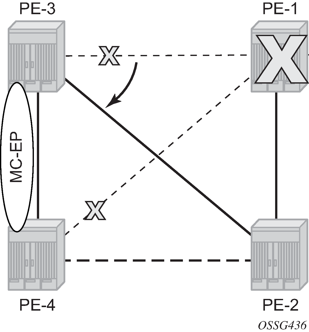
Core node failure
When the core node PE-1 fails, the spoke SDPs 31:1 from PE-3 and 41:1 from PE-4 go down.
Because the spoke SDP 31:1 was active, the MC master (PE-3 in this case) will select the next best spoke SDP, which will be 32:1 (precedence 1). See Core node failure.
*A:PE-3# show service id 2 endpoint

===============================================================================
Service 2 endpoints
===============================================================================
Endpoint name                : CORE
Description                  : (Not Specified)
Creation Origin              : manual
Revert time                  : 0
Act Hold Delay               : 0
Ignore Standby Signaling     : false
Suppress Standby Signaling   : false
Block On Mesh Fail           : true
Multi-Chassis Endpoint       : 1
MC Endpoint Peer Addr        : 192.0.2.4
Psv Mode Active              : No
Tx Active (SDP)              : 32:1
Tx Active Up Time            : 0d 00:00:11
Revert Time Count Down       : never
Tx Active Change Count       : 2
Last Tx Active Change        : 10/03/2023 06:31:56
-------------------------------------------------------------------------------
Members
-------------------------------------------------------------------------------
Spoke-sdp: 31:1 Prec:0                              Oper Status: Down
Spoke-sdp: 32:1 Prec:1                              Oper Status: Up
===============================================================================
===============================================================================
*A:PE-4# show service id 2 endpoint

===============================================================================
Service 2 endpoints
===============================================================================
Endpoint name                : CORE
Description                  : (Not Specified)
Creation Origin              : manual
Revert time                  : 0
Act Hold Delay               : 0
Ignore Standby Signaling     : false
Suppress Standby Signaling   : false
Block On Mesh Fail           : false
Multi-Chassis Endpoint       : 1
MC Endpoint Peer Addr        : 192.0.2.3
Psv Mode Active              : No
Tx Active                    : none
Tx Active Up Time            : 0d 00:00:00
Revert Time Count Down       : never
Tx Active Change Count       : 0
Last Tx Active Change        : 10/03/2023 05:58:09
-------------------------------------------------------------------------------
Members
-------------------------------------------------------------------------------
Spoke-sdp: 41:1 Prec:2                              Oper Status: Down
Spoke-sdp: 42:1 Prec:3                              Oper Status: Up
===============================================================================
===============================================================================
Multi-chassis node failure
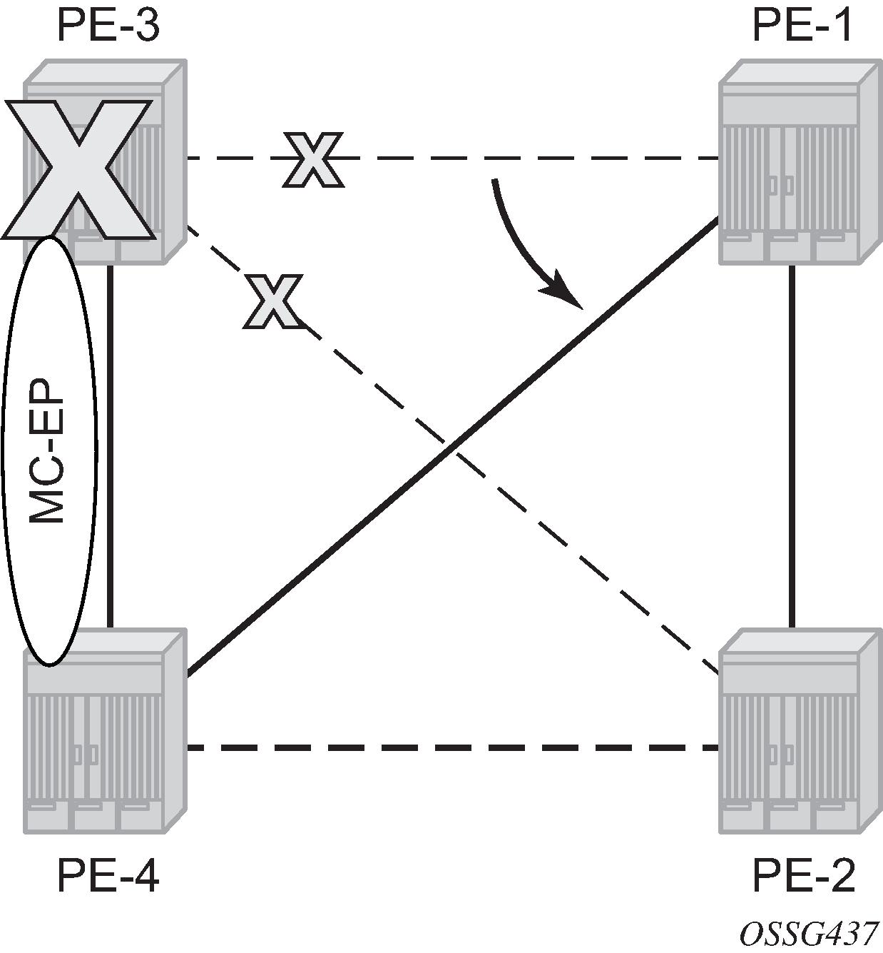
When the multi-chassis node PE-3 fails, both spoke SDPs 31:1 and 32:1 from PE-3 go down.
PE-4 reverts to single chassis mode and selects the best spoke SDP, which will be 41:1 between PE-4 and PE-1 (precedence 2). See Multi-chassis node failure.
*A:PE-4# show redundancy multi-chassis mc-endpoint peer 192.0.2.3

===============================================================================
Multi-Chassis MC-Endpoint
===============================================================================
Peer Addr       : 192.0.2.3           Peer Name            :
Admin State     : up                  Oper State           : down
Last State chg  :                     Source Addr          :
System Id       : 02:17:ff:00:00:00   Sys Priority         : 0
Keep Alive Intvl: 10                  Hold on Nbr Fail     : 3
Passive Mode    : disabled            Psv Mode Oper        : No
Boot Timer      : 300                 BFD                  : enabled
Last update     : 10/03/2023 06:22:54 MC-EP Count          : 1
===============================================================================
*A:PE-4# show service id 2 endpoint

===============================================================================
Service 2 endpoints
===============================================================================
Endpoint name                : CORE
Description                  : (Not Specified)
Creation Origin              : manual
Revert time                  : 0
Act Hold Delay               : 0
Ignore Standby Signaling     : false
Suppress Standby Signaling   : false
Block On Mesh Fail           : false
Multi-Chassis Endpoint       : 1
MC Endpoint Peer Addr        : 192.0.2.3
Psv Mode Active              : No
Tx Active (SDP)              : 41:1
Tx Active Up Time            : 0d 00:00:03
Revert Time Count Down       : never
Tx Active Change Count       : 1
Last Tx Active Change        : 10/03/2023 06:37:38
-------------------------------------------------------------------------------
Members
-------------------------------------------------------------------------------
Spoke-sdp: 41:1 Prec:2                              Oper Status: Up
Spoke-sdp: 42:1 Prec:3                              Oper Status: Up
===============================================================================
Multi-chassis communication failure
If the multi-chassis communication is interrupted, both nodes will revert to single chassis mode.
To simulate a communication failure between the two nodes, define a static route on PE-3 that will blackhole the system address of PE-4.
# on PE-3:
configure
    router Base
        static-route-entry 192.0.2.4/32
            black-hole
                no shutdown
            exit
        exit
Verify that the MC synchronization is operationally down.
*A:PE-4# show redundancy multi-chassis mc-endpoint peer 192.0.2.3

===============================================================================
Multi-Chassis MC-Endpoint
===============================================================================
Peer Addr       : 192.0.2.3           Peer Name            :
Admin State     : up                  Oper State           : down
Last State chg  :                     Source Addr          :
System Id       : 02:17:ff:00:00:00   Sys Priority         : 0
Keep Alive Intvl: 10                  Hold on Nbr Fail     : 3
Passive Mode    : disabled            Psv Mode Oper        : No
Boot Timer      : 300                 BFD                  : enabled
Last update     : 10/03/2023 06:22:54 MC-EP Count          : 1
===============================================================================
The spoke SDPs are active on PE-3 and on PE-4.
*A:PE-3# show service id 2 endpoint | match "Tx Active"
Tx Active (SDP)              : 31:1
Tx Active Up Time            : 0d 00:01:27
Tx Active Change Count       : 10
Last Tx Active Change        : 10/03/2023 06:43:02
*A:PE-4# show service id 2 endpoint | match "Tx Active"
Tx Active (SDP)              : 41:1
Tx Active Up Time            : 0d 00:00:34
Tx Active Change Count       : 5
Last Tx Active Change        : 10/03/2023 06:43:53
This can potentially cause a loop in the system. The Passive mode subsection describes how to avoid this loop.
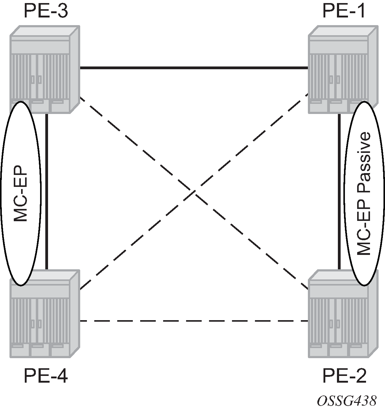
Passive mode
As in the preceding Multi-chassis communication failure subsection, if there is a failure in the multi-chassis communication, both nodes will assume that the peer is down and will revert to single-chassis mode. This can create loops because two spoke SDPs can become active.
One solution is to synchronize the two core nodes, and configure them in passive mode, as illustrated in Multi-chassis passive mode.
In passive mode, both peers will stay dormant as long as one active spoke SDP is signaled from the remote end. If more than one spoke SDP becomes active, the MC-EP algorithm will select the best SDP. All other spoke SDPs are blocked locally (in Rx and Tx directions). There is no signaling sent to the remote PEs.
If one peer is configured in passive mode, the other peer will be forced to passive mode as well.
The no suppress-standby-signaling and no ignore-standby-signaling commands are required.
The following output shows the multi-chassis configuration on PE-1 (similar on PE-2).
# on PE-1:
configure
    redundancy
        multi-chassis
            peer 192.0.2.2 create
                mc-endpoint
                    no shutdown
                    passive-mode
                exit
                no shutdown
            exit
The following output shows the VPLS spoke SDPs configuration on PE-1 (similar on PE-2)
# on PE-1:
configure
    service
        vpls "Core VPLS-1"
            endpoint "METRO1" create
                no suppress-standby-signaling
                mc-endpoint 1
                    mc-ep-peer 192.0.2.2
                exit
            exit
            spoke-sdp 13:1 endpoint "METRO1" create
            exit
            spoke-sdp 14:1 endpoint "METRO1" create
            exit
            no shutdown
To simulate a communication failure between the two nodes, a static route is defined on PE-3 that will blackhole the system address of PE-4.
# on PE-3:
configure
    router Base
        static-route-entry 192.0.2.4/32
            black-hole
                no shutdown
            exit
        exit
The spoke SDPs are active on PE-3 and on PE-4.
*A:PE-3# show service id 2 endpoint | match "Tx Active"
Tx Active (SDP)              : 31:1
Tx Active Up Time            : 0d 00:00:37
Tx Active Change Count       : 12
Last Tx Active Change        : 10/03/2023 07:12:39
*A:PE-4# show service id 2 endpoint | match "Tx Active"
Tx Active (SDP)              : 41:1
Tx Active Up Time            : 0d 00:00:24
Tx Active Change Count       : 7
Last Tx Active Change        : 10/03/2023 07:12:54
PE-1 and PE-2 have blocked one spoke SDP which avoids a loop in the VPLS.
*A:PE-1# show service id 1 endpoint | match "Tx Active"
Tx Active (SDP)              : 13:1
Tx Active Up Time            : 0d 00:01:16
Tx Active Change Count       : 5
Last Tx Active Change        : 10/03/2023 07:12:39
*A:PE-2# show service id 1 endpoint | match "Tx Active"
Tx Active                    : none
Tx Active Up Time            : 0d 00:00:00
Tx Active Change Count       : 2
Last Tx Active Change        : 10/03/2023 07:12:54
The passive nodes do not set the pseudowire status bits; therefore, the nodes PE-3 and PE-4 are not aware that one spoke SDP is blocked.
Conclusion
Multi-chassis endpoint for VPLS active/standby pseudowire allows the building of hierarchical VPLS without single point of failure, and without requiring STP to avoid loops.
Care must be taken to avoid loops. The multi-chassis peer communication is important and should be possible on different interfaces.
Passive mode can be a solution to avoid loops in case of multi-chassis communication failure.