BGP Virtual Private Wire Services
This chapter describes BGP Virtual Private Wire Service (VPWS) configurations.
Topics in this chapter include:
Applicability
This chapter is applicable to SR OS and was initially written for SR OS Release 11.0.R4. The CLI in the current edition is based on SR OS Release 21.2.R1. There are no prerequisites for this configuration.
Overview
The following two IETF standards describe the provisioning of Virtual Private Wire Services (VPWS):
RFC 4447, Pseudowire Setup and Maintenance Using the Label Distribution Protocol (LDP), describes Label Distribution Protocol (LDP) VPWS, where VPWS pseudowires are signaled using LDP between Provider Edge (PE) Routers.
RFC 6624, Layer 2 Virtual Private Networks Using BGP for Auto-Discovery and Signaling, describes the use of Border Gateway Protocol (BGP) for signaling of pseudowires between such PEs.
Example topology shows the example topology with five SR OS routers located in the same Autonomous System (AS). There are three PE routers connected to a single P router and a route reflector (RR) for the AS. The PE routers are all BGP VPWS-aware. The Provider (P) router is BGP VPWS-unaware and does not take part in the BGP process.
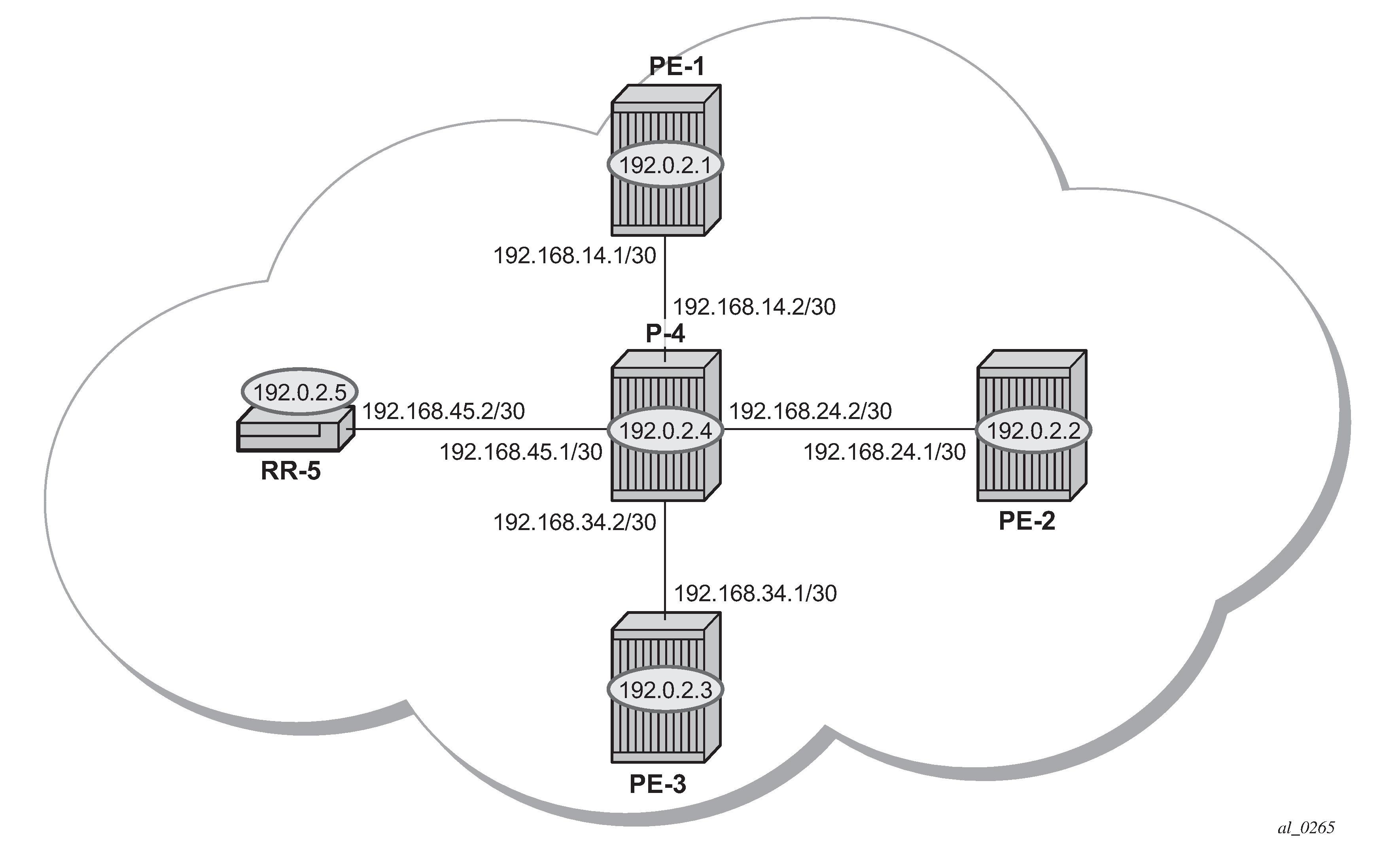
The following configuration tasks are completed as a prerequisite:
IS-IS or OSPF is configured on each of the network interfaces between the PE/P routers and route reflector.
MPLS is configured on all interfaces between PE routers and P routers. It is not required between P-4 and RR-5.
LDP is configured on interfaces between PE and P routers. It is not required between P-4 and the RR-5.
RSVP is configured on interfaces between PE and P routers. It is not required between P-4 and the RR-5.
BGP VPWS
In this architecture, a VPWS is a collection of two (or three in case of redundancy) BGP VPWS service instances present on different PEs in a provider network.
The PEs communicate with each other at the control plane level by means of BGP updates containing BGP VPWS Network Layer Reachability Information (NLRI). Each update contains enough information for a PE to determine the presence of other BGP VPWS instances on peering PEs and to set up pseudowire connectivity for data flow between peers containing the same BGP VPWS service. Therefore, auto-discovery and pseudowire signaling is achieved using a single BGP update message.
Each PE with a BGP VPWS instance is identified by a VPWS edge identifier (VE-ID) and the presence of other BGP VPWS instances is determined using the exchange of standard BGP extended community route targets (RTs) between PEs.
Each PE will advertise, via the RR, the presence of its BGP VPWS instance to all other PEs, along with a block of multiplexer labels (for BGP VPWS, one label per block) that can be used to communicate between each instance, plus a BGP next-hop that determines a labeled transport tunnel to be used between PEs.
Each BGP VPWS instance is configured with import and export route target extended communities for topology control, along with VE identification.
Configuration
The following examples show the configuration of four BGP VPWS scenarios:
Single homed BGP VPWS
using auto-provisioned SDPs
using pre-provisioned SDPs
Dual homed BGP VPWS
with single pseudowire
with active/standby pseudowire
Configure MP-iBGP
The first step is to configure an MP-iBGP session between each of the PEs and the RR. The configuration for all PEs is as follows:
# on PE-1, PE-2, and PE-3:
configure
    router Base
        autonomous-system 65536
        bgp
            group "INTERNAL"
                family l2-vpn
                peer-as 65536
                neighbor 192.0.2.5
                exit
            exit
        exit
The IP addresses can be derived from Example topology.
On RR-5, the BGP configuration is as follows:
# on RR-5:
configure
    router Base
        autonomous-system 65536
        bgp
            group "INTERNAL"
                family l2-vpn
                peer-as 65536
                cluster 1.1.1.1
                neighbor 192.0.2.1
                exit
                neighbor 192.0.2.2
                exit
                neighbor 192.0.2.3
                exit
            exit
        exit
The following command on RR-5 shows that BGP sessions with each PE are established and have a negotiated L2 VPN address family capability.
*A:RR-5# show router bgp summary all

===============================================================================
BGP Summary
===============================================================================
Legend : D - Dynamic Neighbor
===============================================================================
Neighbor
Description
ServiceId          AS PktRcvd InQ  Up/Down   State|Rcv/Act/Sent (Addr Family)
                      PktSent OutQ
-------------------------------------------------------------------------------
192.0.2.1
Def. Instance  65536        5    0 00h01m24s 0/0/0 (L2VPN)
                            5    0
192.0.2.2
Def. Instance  65536        5    0 00h01m24s 0/0/0 (L2VPN)
                            5    0
192.0.2.3
Def. Instance  65536        5    0 00h01m24s 0/0/0 (L2VPN)
                            5    0

-------------------------------------------------------------------------------
Pseudowire templates
BGP VPWS utilizes pseudowire (PW) templates to dynamically instantiate SDP bindings for a service to signal the egress service de-multiplexer labels used by remote PEs to reach the local PE.
The template determines the signaling parameters of the pseudowire, such as vc-type, vlan-vc-tag, hash-label, filters, and so on. The following parameters are recognized by BGP VPWS; the remainder is ignored.
configure
  service
  - pw-template <policy-id> [create] [prefer-provisioned-sdp] [name <name>]
                                                              [auto-gre-sdp]
  - no pw-template <policy-id>
  - pw-template <policy-id> use-provisioned-sdp [create] [name <name>]
       accounting-policy acct-policy-id
       no accounting-policy
       [no] collect-stats
       [no] controlword
       egress
         filter ipv6 <filter-id>
         filter ip <filter-id>
         filter mac <filter-id>
         no filter [ip <filter-id>] [mac <filter-id>] [ipv6 <filter-id>]
         [no] filter-name [ip name] [mac name] [ipv6 name]
         no qos [<network-policy-id>]
         qos <network-policy-id> port-redirect-group <queue-group-name>
                                                     instance <instance-id>
         qos name <network-policy-name> port-redirect-group <queue-group-name>
                                                     instance <instance-id>
       [no] force-vlan-vc-forwarding
       hash-label [signal-capability]
       no hash-label
       entropy-label
       ingress
         filter ipv6 <filter-id>
         filter ip <filter-id>
         filter mac <filter-id>
         no filter [ip <filter-id>] [mac <filter-id>] [ipv6 <filter-id>]
         [no] filter-name [ip name] [mac name] [ipv6 name]
         qos <network-policy-id> fp-redirect-group <queue-group-name>
                                                   instance <instance-id>
         qos name <network-policy-name> fp-redirect-group <queue-group-name>
                                                   instance <instance-id>
         no qos [<network-policy-id>]
       [no] sdp-exclude group-name
       [no] sdp-include group-name
       vc-type {ether | vlan}
       vlan-vc-tag 0..4094
       [no] vlan-vc-tag
Note:
The encapsulation type in the Layer-2 extended community is either 4 (Ethernet VLAN tagged mode) or 5 (Ethernet raw mode), depending on the vc-type parameter.
The force-vlan-vc-forwarding function will add a tag (equivalent to vc-type vlan) and will allow for customer QoS transparency (dot1p + Drop Eligibility (DE) bits).
The MPLS transport tunnel between PEs can be signaled using LDP or RSVP-TE.
LDP-based SDPs can be automatically instantiated or pre-provisioned. RSVP-TE-based SDPs have to be pre-provisioned. If pre-provisioned pseudowires are used, the PW template must be created with the use-provisioned-sdp parameter. Alternatively, the prefer-provisioned-sdp parameter can be used, in which case a pre-provisioned SDP will be used if available; if not, LDP-based SDPs can be automatically instantiated, see chapter LDP VPLS Using BGP Auto-Discovery — Prefer Provisioned SDP.
Pseudowire templates for auto-SDP creation using LDP
In order to use an LDP transport tunnel for data flow between PEs, link layer LDP needs to be configured between all PEs/Ps so that a transport label for each PE system interface is available. For example, on PE-1:
# on PE-1:
configure
    router Base
        ldp
            interface-parameters
                interface "int-PE-1-P-4" dual-stack
                    ipv4
                        no shutdown
                    exit
Using this mechanism, SDPs can be auto-instantiated with SDP-IDs starting at the higher end of the SDP numbering range, such as 32767. Any subsequent SDPs created use SDP-IDs decrementing from this value.
A pseudowire template is required. The following example is created using the default values:
# on PE-1, PE-2, and PE-3:
configure
    service
        pw-template 3 name "PW3" create
        exit
Pseudowire templates for provisioned SDPs using RSVP-TE
RSVP-TE LSPs need to be created between the PE routers on which provisioned SDPs will be used as prerequisite.
The MPLS interface and LSP configuration for PE-1 are:
# on PE-1:
configure
    router Base
        mpls
            interface "int-PE-1-P-4‟
            exit
            path "dyn"
                no shutdown
            exit
            lsp "LSP-PE-1-PE-2"
                to 192.0.2.2
                primary "dyn"
                exit
                no shutdown
            exit
            lsp "LSP-PE-1-PE-3"
                to 192.0.2.3
                primary "dyn"
                exit
                no shutdown
            exit
            no shutdown
The MPLS and LSP configuration for PE-2 are similar to that of PE-1 with the appropriate interfaces and LSP names configured.
To use an RSVP-TE tunnel as transport between PEs, it is necessary to bind the RSVP-TE LSP between PEs to an SDP.
On PE-1, the SDP toward PE-2 is configured as follows. Similar SDPs are required on each PE to the remote PEs in the service where provisioned SDPs are to be used.
# on PE-1:
configure
    service
        sdp 12 mpls create
            description "SDP-PE-1-PE-2_RSVP_BGP"
            signaling bgp
            far-end 192.0.2.2
            lsp "LSP-PE-1-PE-2‟
            no shutdown
        exit
The signaling bgp parameter is required. BGP VPWS instances using BGP VPWS signaling can use BGP-signaled SDPs. However, TLDP-signaled (default) SDPs that are bound to RSVP-based LSPs will not be used as SDPs within BGP VPWS.
Single-homed BGP VPWS using auto-provisioned SDPs
Single-homed BGP VPWS using auto-provisioned SDPs shows a schematic of a single homed BGP VPWS between PE-1 and PE-3 where SDPs are auto-provisioned. In this case, the transport tunnels are LDP-signaled.
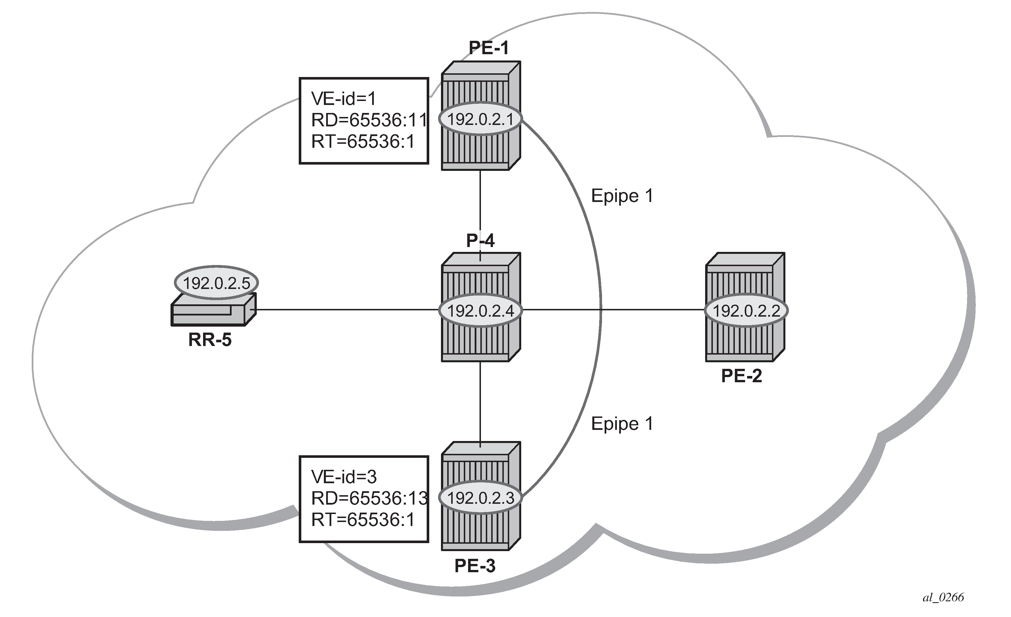
The following shows the configuration required on PE-1 for a BGP VPWS service using a pseudowire template configured for auto-provisioning of SDPs.
# on PE-1:
configure
    service
        pw-template 1 name "PW1" create
            vc-type vlan
        exit
        epipe 1 name "Epipe1" customer 1 create
            bgp
                route-distinguisher 65536:11
                route-target export target:65536:1 import target:65536:1
                pw-template-binding 1
                exit
            exit
            bgp-vpws
                ve-name "PE-1"
                    ve-id 1
                exit
                remote-ve-name "PE-3"
                    ve-id 3
                exit
                no shutdown
            exit
            sap 1/1/4:1 create
            exit
            no shutdown
        exit
The bgp context specifies parameters that are required for BGP VPWS.
Within the bgp context, parameters are configured that are used by the neighboring PEs to determine the membership of a BGP VPWS, in other words, the auto-discovery of PEs in the same BGP VPWS. Within the bgp context, the RD is configured, along with the route target extended communities. Route target communities are used to determine membership of a BGP VPWS. The import and export route targets at the BGP level are mandatory. The PW template binding is then applied and its parameters are used for both the routes sent by this PE and the received routes matching the route target value.
Within the bgp-vpws context, the signaling parameters are configured. These determine the service labels required for the data plane of the VPWS instance.
The VPWS Edge ID (VE-ID) is a numerical value assigned to each PE within a BGP VPWS. This value must be unique for a BGP VPWS, with the exception of multi-homed scenarios, where two dual-homed PEs can have the same VE-ID and are distinguishable by the site preference (or by the tie breaking rules from the draft-ietf-bess-vpls-multihoming-03).
Changes to the pseudowire template are not taken into account once the pseudowire has been set up (changes of RT are refreshed though). PW-templates can be re-evaluated with the tools perform service eval-pw-template command. The eval-pw-template checks if all of the bindings using this PW template policy are still meant to be using this policy. If the template has changed and allow-service-impact is true, then the old binding is removed and it is re-added using the new template.
*A:PE-1# tools perform service eval-pw-template 1
eval-pw-template succeeded for Svc 1 Tx L2 ExtComm, Policy 1
eval-pw-template succeeded for Svc 1 32767:4294967295 Policy 1
VE-ID and BGP label allocations
For a point-to-point VPWS, there are only two members within the BGP VPWS service, so only one label entry is required by each remote service. For dual-homed scenarios, there are two labels for the redundant site, one from each dual-homed PE.
Each PE allocates a label per BGP VPWS instance for the remote PEs, so it signals blocks with one label. It achieves this by advertising three parameters in a BGP update message. For more information about these parameters, see chapter BGP VPLS.
A Label Base (LB) which is the lowest label in the block.
A VE Block size (VBS) which is always 1 and cannot be changed.
A VE Base Offset (VBO) corresponding to the first label in the label block.
PE-3 service creation
On PE-3, Epipe 1 is configured using PW template 1, as follows. PE-3 has been allocated a VE-ID of 3. For completeness, the PW template is also shown.
# on PE-3:
configure
    service
        pw-template 1 name "PW1" create
            vc-type vlan
        exit
        epipe 1 name "Epipe1" customer 1 create
            bgp
                route-distinguisher 65536:13
                route-target export target:65536:1 import target:65536:1
                pw-template-binding 1
                exit
            exit
            bgp-vpws
                ve-name "PE-3"
                    ve-id 3
                exit
                remote-ve-name "PE-1"
                    ve-id 1
                exit
                no shutdown
            exit
            sap 1/1/4:1 create
            exit
            no shutdown
        exit
PE-1 service operation verification
The following command shows that the BGP VPWS service is enabled on PE-1:
*A:PE-1# show service id 1 bgp-vpws

===============================================================================
BGP VPWS Information
===============================================================================
Admin State          : Enabled
VE Name              : PE-1                 VE Id            : 1
PW Tmpl used         : 1

Remote-Ve Information
-------------------------------------------------------------------------------
Remote VE Name       : PE-3                 Remote VE Id     : 3
===============================================================================
The following shows the BGP information used by the BGP VPWS service on PE-1:
*A:PE-1# show service id 1 bgp

===============================================================================
BGP Information
===============================================================================
Vsi-Import           : None
Vsi-Export           : None
Route Dist           : 65536:11
Oper Route Dist      : 65536:11
Oper RD Type         : configured
Rte-Target Import    : 65536:1              Rte-Target Export: 65536:1
Oper RT Imp Origin   : configured           Oper RT Import   : 65536:1
Oper RT Exp Origin   : configured           Oper RT Export   : 65536:1

PW-Template Id       : 1
Endpoint             : <none>
BFD Template         : None
BFD-Enabled          : no                   BFD-Encap        : ipv4
Import Rte-Tgt       : None
-------------------------------------------------------------------------------
===============================================================================
Epipe 1 is operationally up on PE-1, as follows:
*A:PE-1# show service id 1 base

===============================================================================
Service Basic Information
===============================================================================
Service Id        : 1                   Vpn Id            : 0
Service Type      : Epipe
MACSec enabled    : no
Name              : Epipe1
Description       : (Not Specified)
Customer Id       : 1                   Creation Origin   : manual
Last Status Change: 03/04/2021 15:25:11
Last Mgmt Change  : 03/04/2021 15:25:11
Test Service      : No
Admin State       : Up                  Oper State        : Up
MTU               : 1514
Vc Switching      : False
SAP Count         : 1                   SDP Bind Count    : 1
Per Svc Hashing   : Disabled
Vxlan Src Tep Ip  : N/A
Force QTag Fwd    : Disabled
Oper Group        : <none>

-------------------------------------------------------------------------------
Service Access & Destination Points
-------------------------------------------------------------------------------
Identifier                               Type         AdmMTU  OprMTU  Adm  Opr
-------------------------------------------------------------------------------
sap:1/1/4:1                              q-tag        1578    1578    Up   Up
sdp:32767:4294967295 SB(192.0.2.3)       BgpVpws      0       1552    Up   Up
===============================================================================
The SAP and SDP are all operationally up. The indication SB next to the SDP-ID signifies ‟Spoke” and ‟BGP”.
The following output shows the ingress and egress labels for PE-1.
*A:PE-1# show service id 1 sdp

===============================================================================
Services: Service Destination Points
===============================================================================
SdpId            Type     Far End addr    Adm     Opr       I.Lbl     E.Lbl
-------------------------------------------------------------------------------
32767:4294967295 BgpVpws  192.0.2.3       Up      Up        524281    524281
-------------------------------------------------------------------------------
Number of SDPs : 1
-------------------------------------------------------------------------------
===============================================================================
The following debug output from PE-1 shows the BGP VPWS NLRI update for Epipe 1 sent by PE-1 to RR-5. This update will then be received by the other PEs.
# on PE-1:
debug
    router "Base"
        bgp
            update
3 2021/03/04 15:25:41.024 UTC MINOR: DEBUG #2001 Base Peer 1: 192.0.2.5
"Peer 1: 192.0.2.5: UPDATE
Peer 1: 192.0.2.5 - Send BGP UPDATE:
    Withdrawn Length = 0
    Total Path Attr Length = 76
    Flag: 0x90 Type: 14 Len: 32 Multiprotocol Reachable NLRI:
        Address Family L2VPN
        NextHop len 4 NextHop 192.0.2.1
        [VPLS/VPWS] preflen 21, veid: 1, vbo: 3, vbs: 1, label-base: 524281,
                    RD 65536:11, csv: 0x00000000, type 1, len 1,
    Flag: 0x40 Type: 1 Len: 1 Origin: 0
    Flag: 0x40 Type: 2 Len: 0 AS Path:
    Flag: 0x80 Type: 4 Len: 4 MED: 0
    Flag: 0x40 Type: 5 Len: 4 Local Preference: 100
    Flag: 0xc0 Type: 16 Len: 16 Extended Community:
        target:65536:1
        l2-vpn/vrf-imp:Encap=4: Flags=none: MTU=1514: PREF=0
"
The control flags within the extended community indicate the status of the BGP VPWS instance.
The control flags are the following:
0 1 2 3 4 5 6 7
+-+-+-+-+-+-+-+-+
|D|A|F|Z|Z|Z|C|S| (Z = MUST Be Zero)
+-+-+-+-+-+-+-+-+
D: access circuit down indicator. D is 1 if all access circuits are down, otherwise D is 0.
A: automatic site ID allocation, which is not supported. This is ignored on receipt and set to 0 on sending.
F: MAC flush indicator, this relates to VPLS. This is set to 0 and ignored on receipt.
C: presence of a control word. Control word usage is not supported. This is set to 0 on sending (control word not present) and if a non-zero value is received (indicating a control word is required), the pseudowire will not be created.
S: sequenced delivery. Sequenced delivery is not supported. This is set to 0 on sending (no sequenced delivery) and if a non-zero value is received (indicating sequenced delivery required), the pseudowire will not be created.
The BGP VPWS NLRI is based on the BGP VPLS NLRI, but is extended with a Circuit Status Vector (CSV). The circuit status vector is used to indicate the status of both the SAP and the spoke-SDP within the local service. Because the VE block size used is 1, the most significant bit in the circuit status vector TLV value will be set to 1 if either the SAP or spoke-SDP is down; otherwise, it will be set to 0.
# on PE-1:
configure
    service
        epipe "Epipe1"
            sap 1/1/4:1
                shutdown
6 2021/03/04 15:31:59.024 UTC MINOR: DEBUG #2001 Base Peer 1: 192.0.2.5
"Peer 1: 192.0.2.5: UPDATE
Peer 1: 192.0.2.5 - Send BGP UPDATE:
    Withdrawn Length = 0
    Total Path Attr Length = 76
    Flag: 0x90 Type: 14 Len: 32 Multiprotocol Reachable NLRI:
        Address Family L2VPN
        NextHop len 4 NextHop 192.0.2.1
        [VPLS/VPWS] preflen 21, veid: 1, vbo: 3, vbs: 1, label-base: 524281,
                    RD 65536:11, csv: 0x00000080, type 1, len 1,
    Flag: 0x40 Type: 1 Len: 1 Origin: 0
    Flag: 0x40 Type: 2 Len: 0 AS Path:
    Flag: 0x80 Type: 4 Len: 4 MED: 0
    Flag: 0x40 Type: 5 Len: 4 Local Preference: 100
    Flag: 0xc0 Type: 16 Len: 16 Extended Community:
        target:65536:1
        l2-vpn/vrf-imp:Encap=4: Flags=D: MTU=1514: PREF=0
"
After disabling the local SAP, the CSV has the most significant bit set to 1 (0x80). The following command shows the BGP VPWS update received on PE-3:
*A:PE-3# show service l2-route-table bgp-vpws detail

===============================================================================
Services: L2 Bgp-Vpws Route Information - Summary
===============================================================================

Svc Id         : 1
VeId           : 1
PW Temp Id     : 1
RD             : *65536:11
Next Hop       : 192.0.2.1
State (D-Bit)  : down(1)
Path MTU       : 1514
Control Word   : 0
Seq Delivery   : 0
Status         : active
Tx Status      : active
CSV            : 80
Preference     : 0
Sdp Bind Id    : 32767:4294967295
===============================================================================
On PE-1, SAP 1/1/4:1 is re-enabled as follows:
# on PE-1:
configure
    service
        epipe "Epipe1"
            sap 1/1/4:1
                no shutdown
            exit
PE-3 service operation verification
Similar to PE-1, the service operation should be validated on PE-3.
Single-homed BGP VPWS using pre-provisioned SDP
It is possible to configure BGP VPWS instances that use RSVP-TE transport tunnels. In this case, the SDPs must be created with the MPLS LSPs mapped and with the signaling set to BGP, because the service labels are signaled using BGP. The PW template configured within the BGP VPWS instance must use the keyword use-provisioned-sdp (or prefer-provisioned-sdp).
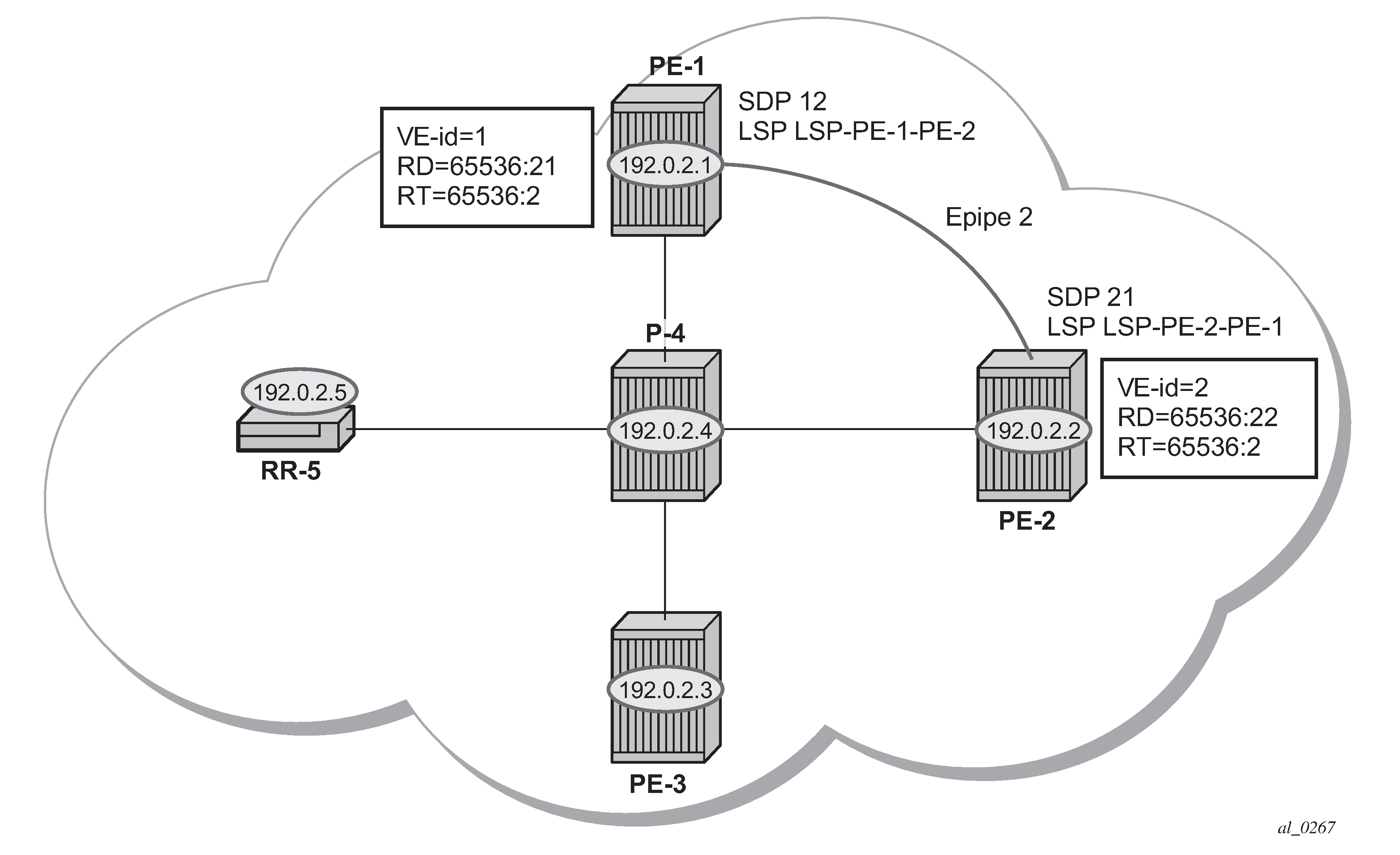
Single-homed BGP VPWS using pre-provisioned SDP shows a schematic of a BGP VPWS where SDPs are pre-provisioned with RSVP-TE signaled transport tunnels.
On PE-1, SDP 12 toward PE-2 is configured as follows:
# on PE-1:
configure
    service
        sdp 12 mpls create
            description "SDP-PE-1-PE-2_RSVP_BGP"
            signaling bgp
            far-end 192.0.2.2
            lsp "LSP-PE-1-PE-2"
            no shutdown
        exit
On PE-2, SDP 21 toward PE-1 is configured as follows:
# on PE-2:
configure
    service
        sdp 21 mpls create
            description "SDP-PE-2-PE-1_RSVP_BGP"
            signaling bgp
            far-end 192.0.2.1
            lsp "LSP-PE-2-PE-1"
            no shutdown
        exit
To create a spoke SDP within a service that uses the RSVP-TE transport tunnel, a pseudowire template is required that has the use-provisioned-sdp parameter set.
The PW template is provisioned on both PEs as follows:
# on PE-1 and PE-2:
configure
    service
        pw-template 2 name "PW2" use-provisioned-sdp create
        exit
The following output shows the configuration required for a BGP VPWS service using a PW template configured for using pre-provisioned RSVP-TE SDPs.
# on PE-1:
configure
    service
        epipe 2 name "Epipe2" customer 1 create
            bgp
                route-distinguisher 65536:21
                route-target export target:65536:2 import target:65536:2
                pw-template-binding 2
                exit
            exit
            bgp-vpws
                ve-name "PE-1"
                    ve-id 1
                exit
                remote-ve-name "PE-2"
                    ve-id 2
                exit
                no shutdown
            exit
            sap 1/1/4:2 create
            exit
            no shutdown
The route distinguisher and route target extended community values for Epipe 2 are different from that in Epipe 1. This is to differentiate between the two as their visibility is global within the BGP domain. The VE-ID values can be reused in each Epipe instance, as long as they are unique within the instance.
Similarly, the configuration is as follows on PE-2, where the VE-ID is 2:
# on PE-2:
configure
    service
         epipe 2 name "Epipe2" customer 1 create
            bgp
                route-distinguisher 65536:22
                route-target export target:65536:2 import target:65536:2
                pw-template-binding 2
                exit
            exit
            bgp-vpws
                ve-name "PE-2"
                    ve-id 2
                exit
                remote-ve-name "PE-1"
                    ve-id 1
                exit
                no shutdown
            exit
            sap 1/1/4:2 create
            exit
            no shutdown
The service Epipe 2 is operationally up on PE-1, as follows:
*A:PE-1# show service id 2 base

===============================================================================
Service Basic Information
===============================================================================
Service Id        : 2                   Vpn Id            : 0
Service Type      : Epipe
---snip---

Admin State       : Up                  Oper State        : Up
---snip---

-------------------------------------------------------------------------------
Service Access & Destination Points
-------------------------------------------------------------------------------
Identifier                               Type         AdmMTU  OprMTU  Adm  Opr
-------------------------------------------------------------------------------
sap:1/1/4:2                              q-tag        1578    1578    Up   Up
sdp:12:4294967294 S(192.0.2.2)           BgpVpws      0       1552    Up   Up
===============================================================================
The SDP-ID is the pre-provisioned SDP 12.
For completeness, the following command shows that the service is operationally up on PE-2.
*A:PE-2# show service id 2 base

===============================================================================
Service Basic Information
===============================================================================
Service Id        : 2                   Vpn Id            : 0
Service Type      : Epipe
---snip---

Admin State       : Up                  Oper State        : Up
---snip---

-------------------------------------------------------------------------------
Service Access & Destination Points
-------------------------------------------------------------------------------
Identifier                               Type         AdmMTU  OprMTU  Adm  Opr
-------------------------------------------------------------------------------
sap:1/1/4:2                              q-tag        1578    1578    Up   Up
sdp:21:4294967295 S(192.0.2.1)           BgpVpws      0       1552    Up   Up
===============================================================================
The SDP-ID used is the pre-provisioned SDP 21.
Dual-homed BGP VPWS with single pseudowire
For access redundancy, an Epipe using a BGP VPWS service can be configured as dual-homed, as described in draft-ietf-bess-vpls-multihoming-03. It can be configured with a single pseudowire setup, where the redundant pseudowire is not created until the initially active pseudowire is removed.
The following diagram shows a setup where an Epipe is configured on each PE. Site B is dual-homed to PE-1 and PE-3 with the remote PE-2 connected to site A; each site connection uses a SAP. A single pseudowire using Ethernet Raw Mode encapsulation connects PE-2 to PE-1 or PE-3 (but not both at the same time). The pseudowire is signaled using BGP VPWS over a tunnel LSP between the PEs.
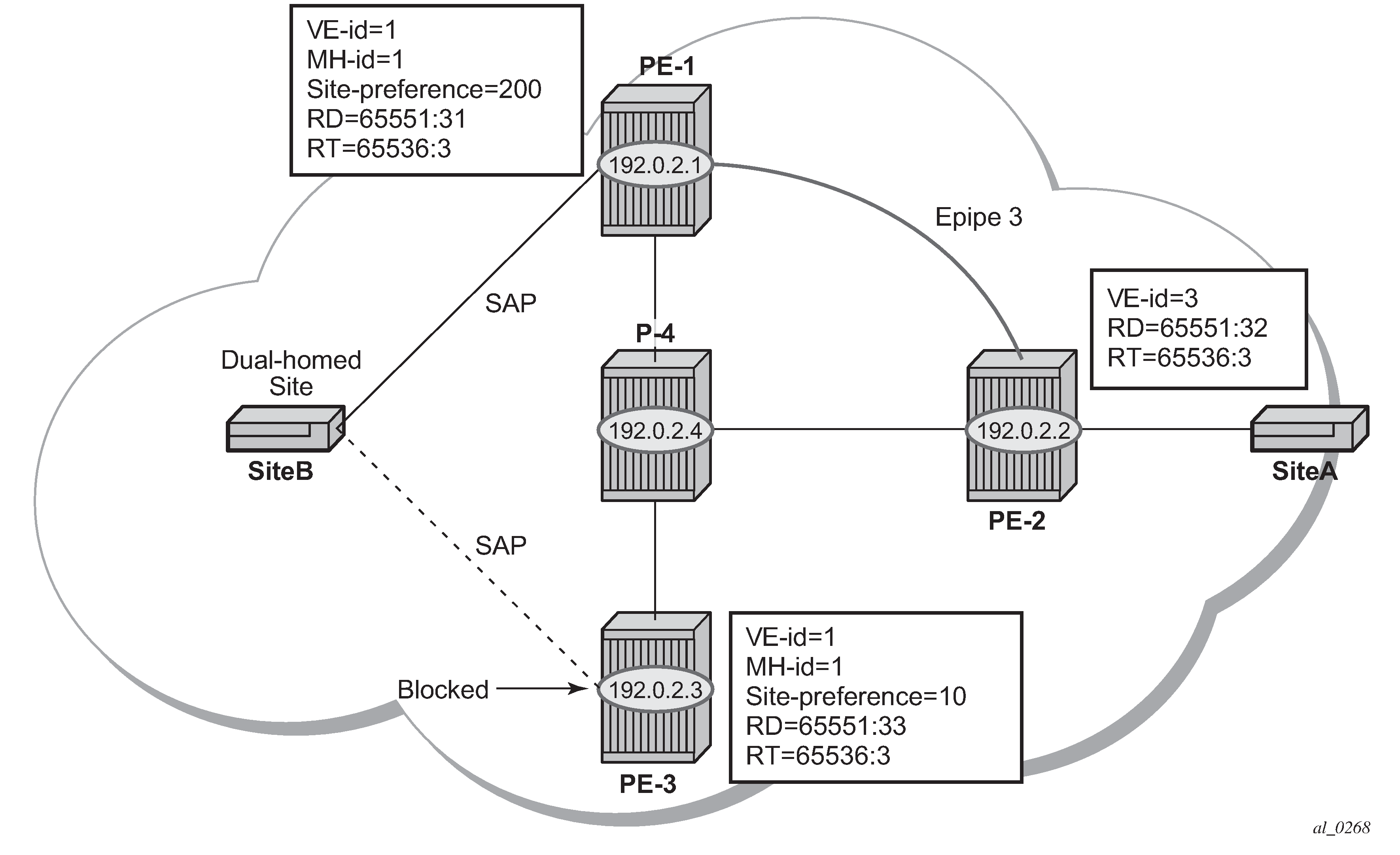
BGP multi-homing is configured for the dual-homed site B using a site-ID=1. The site-preference on PE-1 is set to 200 and to 10 on PE-3, this ensures that PE-1 will be the site’s Designated Forwarder (DF) and the pseudowire from PE-2 will be created to PE-1 when PE-1 is fully operational (no pseudowire is created on PE-2 to PE-3). If PE-1 fails, or the multi-homing site fails over to PE-3, then the pseudowire from PE-2 to PE-1 will be removed and a new pseudowire will be created from PE-2 to PE-3.
On PE-1, Epipe 3 is configured as follows:
# on PE-1:
configure
    service
         pw-template 3 name "PW3" create
         exit
         epipe 3 name "Epipe3" customer 1 create
            bgp
                route-distinguisher 65536:31
                route-target export target:65536:3 import target:65536:3
                pw-template-binding 3
                exit
            exit
            bgp-vpws
                ve-name "PE-1"
                    ve-id 1
                exit
                remote-ve-name "PE-2"
                    ve-id 2
                exit
                no shutdown
            exit
            site "SITEB" create
                site-id 1
                sap 1/1/4:3
                site-preference 200
                no shutdown
            exit
            sap 1/1/4:3 create
            exit
            no shutdown
        exit
Epipe 3 is configured on PE-3 with the same VE-ID as on PE-1, as follows:
# on PE-3:
configure
    service
        pw-template 3 name "PW3" create
        exit
        epipe 3 name "Epipe3" customer 1 create
            bgp
                route-distinguisher 65536:33
                route-target export target:65536:3 import target:65536:3
                pw-template-binding 3
                exit
            exit
            bgp-vpws
                ve-name "PE-3"
                    ve-id 1
                exit
                remote-ve-name "PE-2"
                    ve-id 2
                exit
                no shutdown
            exit
            site "SITEB" create
                site-id 1
                sap 1/1/4:3
                site-preference 10
                no shutdown
            exit
            sap 1/1/4:3 create
            exit
            no shutdown
        exit
In the preceding configurations, the remote-ve-name for PE-2 uses VE-ID 2 on both PE-1 and PE-3.
Epipe 3 is configured on PE-2 as follows:
# on PE-2:
configure
    service
        pw-template 3 name "PW3" create
        exit
        epipe 3 name "Epipe3" customer 1 create
            bgp
                route-distinguisher 65536:32
                route-target export target:65536:3 import target:65536:3
                pw-template-binding 3
                exit
            exit
            bgp-vpws
                ve-name "PE-2"
                    ve-id 2
                exit
                remote-ve-name "PE-1 or PE-3"
                    ve-id 1
                exit
                no shutdown
            exit
            sap 1/1/4:3 create
            exit
            no shutdown
        exit
On PE-2, the remote-ve-name is configured as ‟PE-1 or PE-3”; this is because both of these PEs are configured with VE-ID 1.
As a result of this configuration, there are multiple route entries for RD 65536:31 on PE-2. In the BGP routing table, there are two entries per partner PE, one for the BGP-MH update (with site-ID=1) and the other for the BGP-VPWS update (with VE-ID=1).
*A:PE-2# show router bgp routes l2-vpn rd 65536:31
===============================================================================
 BGP Router ID:192.0.2.2        AS:65536       Local AS:65536
===============================================================================
 Legend -
 Status codes  : u - used, s - suppressed, h - history, d - decayed, * - valid
                 l - leaked, x - stale, > - best, b - backup, p - purge
 Origin codes  : i - IGP, e - EGP, ? - incomplete

===============================================================================
BGP L2VPN Routes
===============================================================================
Flag  RouteType                   Prefix                             MED
      RD                          SiteId                             Label
      Nexthop                     VeId                   BlockSize   LocalPref
      As-Path                     BaseOffset             vplsLabelBa
                                                         se
-------------------------------------------------------------------------------
u*>i  MultiHome                   -                      -           0
      65536:31                    1                                  -
      192.0.2.1                   -                      -           200
      No As-Path                  -                      -
u*>i  VPWS                        -                      -           0
      65536:31                    -                                  -
      192.0.2.1                   1                      1           200
      No As-Path                  2                      524279
-------------------------------------------------------------------------------
Routes : 2
===============================================================================
*A:PE-2# show router bgp routes l2-vpn rd 65536:33
===============================================================================
 BGP Router ID:192.0.2.2        AS:65536       Local AS:65536
===============================================================================
 Legend -
 Status codes  : u - used, s - suppressed, h - history, d - decayed, * - valid
                 l - leaked, x - stale, > - best, b - backup, p - purge
 Origin codes  : i - IGP, e - EGP, ? - incomplete

===============================================================================
BGP L2VPN Routes
===============================================================================
Flag  RouteType                   Prefix                             MED
      RD                          SiteId                             Label
      Nexthop                     VeId                   BlockSize   LocalPref
      As-Path                     BaseOffset             vplsLabelBa
                                                         se
-------------------------------------------------------------------------------
u*>i  MultiHome                   -                      -           0
      65536:33                    1                                  -
      192.0.2.3                   -                      -           10
      No As-Path                  -                      -
u*>i  VPWS                        -                      -           0
      65536:33                    -                                  -
      192.0.2.3                   1                      1           10
      No As-Path                  2                      524280
-------------------------------------------------------------------------------
Routes : 2
===============================================================================
The route to PE-1 has the higher site preference, so it is selected as the target for the pseudowire.
*A:PE-2# show service l2-route-table bgp-vpws detail

===============================================================================
Services: L2 Bgp-Vpws Route Information - Summary
===============================================================================

---snip---

Svc Id         : 3
VeId           : 1
PW Temp Id     : 3
RD             : *65536:31
Next Hop       : 192.0.2.1
State (D-Bit)  : up(0)
Path MTU       : 1514
Control Word   : 0
Seq Delivery   : 0
Status         : active
Tx Status      : active
CSV            : 0
Preference     : 200
Sdp Bind Id    : 32767:4294967292
===============================================================================
After disabling the SAP in the service on PE-1, BGP update messages are received. The VPLS/VPWS message received on PE-2 from PE-1 shows in the CSV that the access circuit is down (the CSV has the most-significant bit set to 1 (0x80)), so PE-2 selects the update from PE-3 to create the pseudowire. The BGP-MH update received by PE-2 from PE-1 also shows that the local site is down as indicated by the flags=D.
Note in the following debug output:
BGP MH (multi-homing) entry uses encap-type=19.
BGP VPWS entry uses encap-type=5 (Ethernet raw mode).
# Disable SAP in Epipe 3 on PE-1:
configure
    service
        epipe "Epipe3"
            sap 1/1/4:3
                shutdown
34 2021/03/04 15:56:35.904 UTC MINOR: DEBUG #2001 Base Peer 1: 192.0.2.5 "Peer 1: 192.0.2.5: UPDATE Peer 1: 192.0.2.5 - Received BGP UPDATE: Withdrawn Length = 0 Total Path Attr Length = 90 Flag: 0x90 Type: 14 Len: 32 Multiprotocol Reachable NLRI: Address Family L2VPN NextHop len 4 NextHop 192.0.2.1 [VPLS/VPWS] preflen 21, veid: 1, vbo: 2, vbs: 1, label-base: 524279, RD 65536:31, csv: 0x00000080, type 1, len 1, Flag: 0x40 Type: 1 Len: 1 Origin: 0 Flag: 0x40 Type: 2 Len: 0 AS Path: Flag: 0x80 Type: 4 Len: 4 MED: 0 Flag: 0x40 Type: 5 Len: 4 Local Preference: 0 Flag: 0x80 Type: 9 Len: 4 Originator ID: 192.0.2.1 Flag: 0x80 Type: 10 Len: 4 Cluster ID: 1.1.1.1 Flag: 0xc0 Type: 16 Len: 16 Extended Community: target:65536:3 l2-vpn/vrf-imp:Encap=5: Flags=D: MTU=1514: PREF=200 "35 2021/03/04 15:56:35.904 UTC MINOR: DEBUG #2001 Base Peer 1: 192.0.2.5 "Peer 1: 192.0.2.5: UPDATE Peer 1: 192.0.2.5 - Received BGP UPDATE: Withdrawn Length = 0 Total Path Attr Length = 86 Flag: 0x90 Type: 14 Len: 28 Multiprotocol Reachable NLRI: Address Family L2VPN NextHop len 4 NextHop 192.0.2.1 [MH] site-id: 1, RD 65536:31 Flag: 0x40 Type: 1 Len: 1 Origin: 0 Flag: 0x40 Type: 2 Len: 0 AS Path: Flag: 0x80 Type: 4 Len: 4 MED: 0 Flag: 0x40 Type: 5 Len: 4 Local Preference: 0 Flag: 0x80 Type: 9 Len: 4 Originator ID: 192.0.2.1 Flag: 0x80 Type: 10 Len: 4 Cluster ID: 1.1.1.1 Flag: 0xc0 Type: 16 Len: 16 Extended Community: target:65536:3 l2-vpn/vrf-imp:Encap=19: Flags=D: MTU=0: PREF=200 "
The result can be shown on PE-2 because the spoke SDP to PE-3 is now up (active).
*A:PE-2# show service l2-route-table bgp-vpws detail

===============================================================================
Services: L2 Bgp-Vpws Route Information - Summary
===============================================================================

---snip---

Svc Id         : 3
VeId           : 1
PW Temp Id     : 3
RD             : *65536:33
Next Hop       : 192.0.2.3
State (D-Bit)  : up(0)
Path MTU       : 1514
Control Word   : 0
Seq Delivery   : 0
Status         : active
Tx Status      : active
CSV            : 0
Preference     : 10
Sdp Bind Id    : 32767:4294967291
===============================================================================
Dual-homed BGP VPWS with active/standby pseudowire
The second method for BGP VPWS pseudowire redundancy is an active/standby configuration. Whereas in the solution with one pseudowire, the redundant nodes use the same VE-ID for the remote PE and different preferences; in the active/standby solution, the redundant nodes use different VE-IDs for the remote PE and different preferences. The node connecting to both pseudowires (PE-2 in this example) has both remote VE-IDs configured. This allows for faster failover because the standby pseudowire is instantiated in addition to the active pseudowire. If more than two applicable BGP updates are received, at most one standby pseudowire is created (based on the BGP VPWS tie breaking rules).
Dual-homed BGP VPWS with active/standby pseudowire shows a setup where an Epipe is configured on each PE. Site B is dual-homed to PE-1 and PE-3 with the remote PE-2 connected to site A; each site connection uses a SAP. The active/standby pseudowires using Ethernet raw mode encapsulation connect PE-2 to PE-1 and PE-3. The pseudowires are signaled using BGP VPWS over tunnel LSPs between the PEs.
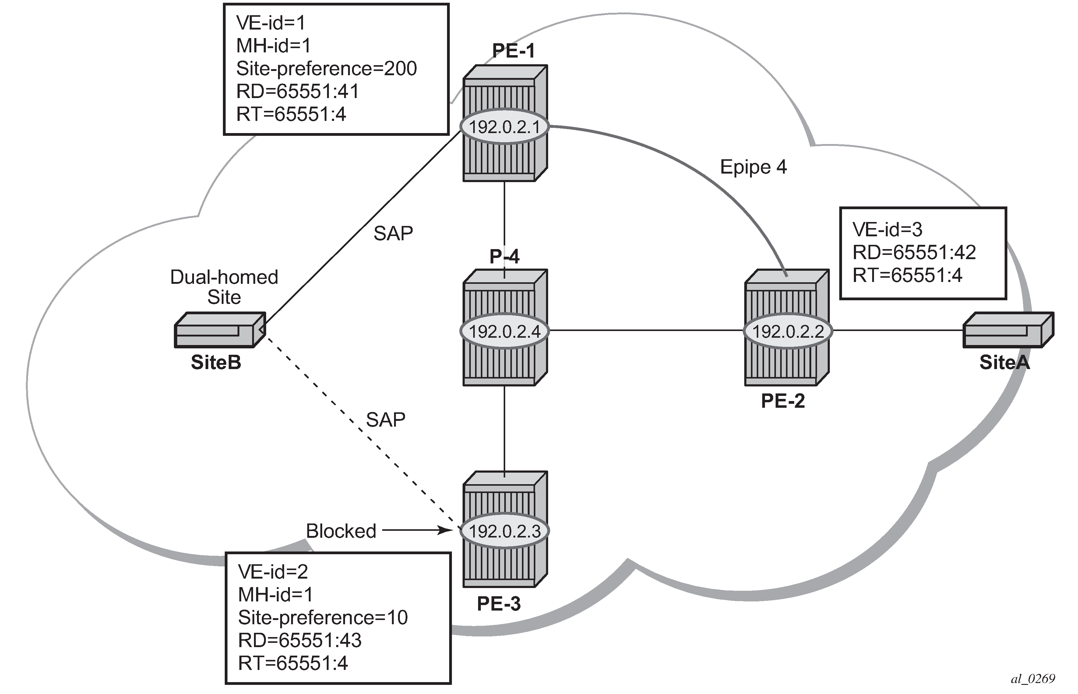
BGP Multi-Homing (MH) is configured for the dual-homed site B using a site-ID=1. The site preference on PE-1 is set to 200 and to 10 on PE-3; this ensures that PE-1 will be the site’s DF for the MH site. The active pseudowire from PE-2 will be created to PE-1 with the standby pseudowire being created to PE-3. If PE-1 fails, or the multi-homing site fails over to PE-3, then the pseudowire from PE-2 to PE-3 will become active (used as the data path between site A and B).
Epipe 4 is configured on PE-1 as follows:
# on PE-1:
configure
    service
         pw-template 3 name "PW3" create
         exit
         epipe 4 name "Epipe4" customer 1 create
            bgp
                route-distinguisher 65536:41
                route-target export target:65536:4 import target:65536:4
                pw-template-binding 3
                exit
            exit
            bgp-vpws
                ve-name "PE-1"
                    ve-id 1
                exit
                remote-ve-name "PE-2"
                    ve-id 2
                exit
                no shutdown
            exit
            site "SITEB" create
                site-id 1
                sap 1/1/4:4
                site-preference 200
                no shutdown
            exit
            sap 1/1/4:4 create
            exit
            no shutdown
        exit
Epipe 4 is configured on PE-3 with local VE-ID is 3 (different from previous example), as follows:
# on PE-3:
configure
    service
         pw-template 3 name "PW3" create
         exit
         epipe 4 name "Epipe4" customer 1 create
            bgp
                route-distinguisher 65536:43
                route-target export target:65536:4 import target:65536:4
                pw-template-binding 3
                exit
            exit
            bgp-vpws
                ve-name "PE-3"
                    ve-id 3
                exit
                remote-ve-name "PE-2"
                    ve-id 2
                exit
                no shutdown
            exit
            site "SITEB" create
                site-id 1
                sap 1/1/4:4
                site-preference 10
                no shutdown
            exit
            sap 1/1/4:4 create
            exit
            no shutdown
        exit
Epipe 4 is configured on PE-2 as follows. Two remote VE names are configured, PE-1 and PE-3 (this is the maximum number allowed).
# on PE-2:
configure
    service
         pw-template 3 name "PW3" create
         exit
         epipe 4 name "Epipe4" customer 1 create
            bgp
                route-distinguisher 65536:42
                route-target export target:65536:4 import target:65536:4
                pw-template-binding 3
                exit
            exit
            bgp-vpws
                ve-name "PE-2"
                    ve-id 2
                exit
                remote-ve-name "PE-1"
                    ve-id 1
                exit
                remote-ve-name "PE-3"
                    ve-id 3
                exit
                no shutdown
            exit
            sap 1/1/4:4 create
            exit
            no shutdown
Compared with the single pseudowire solution, both pseudowires are signaled and up on all PEs. The pseudowire with the higher preference is forwarding traffic (to PE-1), while the Tx status to the standby PE-3 is set to inactive, as follows:
*A:PE-2# show service l2-route-table bgp-vpws detail

===============================================================================
Services: L2 Bgp-Vpws Route Information - Summary
===============================================================================

---snip---

Svc Id         : 4
VeId           : 1
PW Temp Id     : 3
RD             : *65536:41
Next Hop       : 192.0.2.1
State (D-Bit)  : up(0)
Path MTU       : 1514
Control Word   : 0
Seq Delivery   : 0
Status         : active
Tx Status      : active
CSV            : 0
Preference     : 200
Sdp Bind Id    : 32767:4294967289

Svc Id         : 4
VeId           : 3
PW Temp Id     : 3
RD             : *65536:43
Next Hop       : 192.0.2.3
State (D-Bit)  : up(0)
Path MTU       : 1514
Control Word   : 0
Seq Delivery   : 0
Status         : active
Tx Status      : inactive
CSV            : 0
Preference     : 10
Sdp Bind Id    : 32766:4294967288
===============================================================================
The choice of pseudowire to be used to transmit traffic from PE-2 to PE-1 can also be seen in the endpoint created in the BGP VPWS service. Endpoints are automatically created for the pseudowires within a BGP VPWS service, regardless of whether active/standby pseudowires are used; these endpoints are created with a system generated name that ends with the BGP VPWS service id.
*A:PE-2# show service id 4 endpoint

===============================================================================
Service 4 endpoints
===============================================================================
Endpoint name                : _tmnx_BgpVpws-4
Description                  : Automatically created BGP-VPWS endpoint
Creation Origin              : bgpVpws
Revert time                  : 0
Act Hold Delay               : 0
Standby Signaling Master     : false
Standby Signaling Slave      : false
Tx Active (SDP)              : 32767:4294967289
Tx Active Up Time            : 0d 00:02:07
Revert Time Count Down       : never
Tx Active Change Count       : 3
Last Tx Active Change        : 03/04/2021 16:04:40
-------------------------------------------------------------------------------
Members
-------------------------------------------------------------------------------
Spoke-sdp: 32766:4294967288 Prec:4                  Oper Status: Up
Spoke-sdp: 32767:4294967289 Prec:4                  Oper Status: Up
===============================================================================
===============================================================================
The following command has no effect on an automatically created VPWS endpoint.
tools perform service id <service-id> endpoint <endpoint-name> force-switchover <..>
Conclusion
BGP VPWS allows the delivery of Layer 2 virtual private wire services to customers where BGP is commonly used. This chapter shows the configuration of single and dual-homed BGP VPWS services together with the associated show output, which can be used to verify and troubleshoot them.