VXLAN Forwarding Path Extension
This chapter provides information about VXLAN Forwarding Path Extension.
Topics in this chapter include:
Applicability
This chapter was initially written based on SR OS Release 15.0.R4, but the CLI in the current edition corresponds to SR OS Release 21.2.R2. Virtual eXtensible Local Area Network (VXLAN) Forwarding Path Extension (FPE) is supported in SR OS Release 14.0.R4, and later. IPv6 addresses are supported for EVPN-VXLAN BGP peering in SR OS Release 15.0.R1, and later.
Overview
Use cases
VXLAN Forwarding Path Extension (FPE) is an SR OS feature that enables VXLAN tunnels to terminate on non-system IPv4 and IPv6 Destination Addresses (DAs). The non-system IPv4/IPv6 VXLAN termination feature can be applied in the following use cases:
VXLAN Gateway (GW) in Software-Defined VPNs (SD-VPNs)
VXLAN IPv6 underlay for Data Centers (DCs)
VXLAN GW in SD-VPNs
Traffic transported on a VXLAN is usually connected to a trusted environment through a VPRN running in a private IP/MPLS network. The VXLAN GW system IP address is used for all internal management and MPLS termination in the trusted network. However, in this use case, SR OS routers are expected to be used as a VXLAN GW in SD-VPNs where the VXLAN GW terminates untrusted VXLAN tunnels initiated on the SD-VPN CPEs and forwards packets to a trusted IP/MPLS network, as shown in VXLAN GW in an SD-VPN.
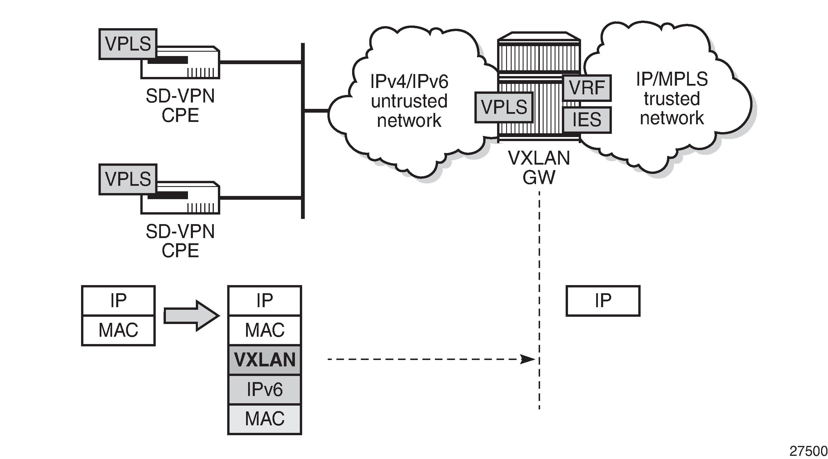
For security reasons, service providers will not expose system IP addresses to the untrusted IP network. Therefore, an IPv4 or IPv6 loopback address will be defined and used for VXLAN termination. The VXLAN tunnel can be terminated in a VPLS, an Epipe, or an R-VPLS service connected to a VPRN.
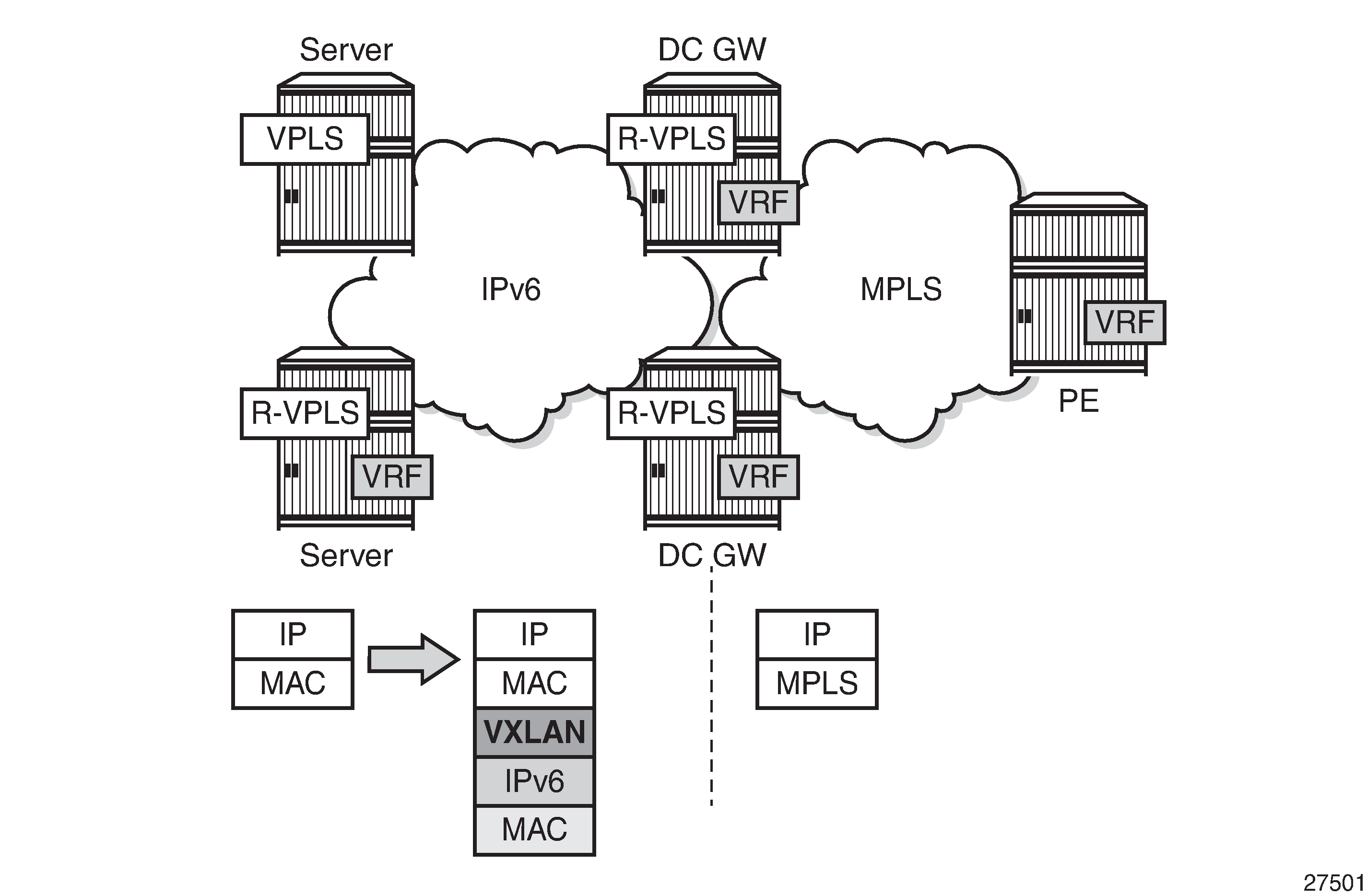
VXLAN IPv6 underlay for DCs
Some service providers migrate their entire network infrastructure to IPv6, including the DC network, so the DC GW must be able to terminate a VXLAN over an IPv6 infrastructure. Layer 2 (VPLS termination) and Layer 3 (R-VPLS termination) DC interconnect are both supported. VXLAN IPv6 underlay for DC shows the VXLAN IPv6 underlay for DC.
VXLAN FPE function
The following applies to VXLAN FPE:
In an SR OS node, VXLAN tunnels can be terminated in four different VXLAN Tunnel Endpoints (VTEPs):
System IPv4 address
Up to three non-system IPv4/IPv6 addresses
This limit is based on the number of supported source IP addresses that can be used for VXLAN encapsulation.
The preceding four terminating IP addresses can be used in addition to the Assisted Replication IP address (AR IP). The AR IP does not count against this limit of four VTEPs. See chapter Layer 2 Multicast Optimization for EVPN-VXLAN — Assisted Replication for more information about AR.
VXLAN FPE requires PXC ports; see chapter Port Cross-connect (PXC).
Ingress traffic from a VXLAN with an IP DA equal to a loopback address will be redirected to the PXC port where the IP header will get additional processing.
Usually, only the ingress traffic from the VXLAN is redirected to the PXC port. The egress traffic to the VXLAN tunnel can go straight out of the egress network port, except for R-VPLS traffic toward an IPv6 VXLAN that is redirected to the PXC port.
The VPLS/R-VPLS functionality is not impacted by the choice of VTEP termination (system IP address or not).
Provisioning model
Non-system IP VXLAN termination and VXLAN IPv6 underlay are both provisioned as per the following steps:
Create an FPE
Associate the FPE with VXLAN termination
Configure a router loopback interface
Configure non-system VXLAN termination VTEP addresses
Add the service configuration
Configuration
Example topology for VXLAN FPE shows the example topology with two PEs in an EVPN-VXLAN network. The loopback addresses in the base router will be used for non-system IP VXLAN termination.
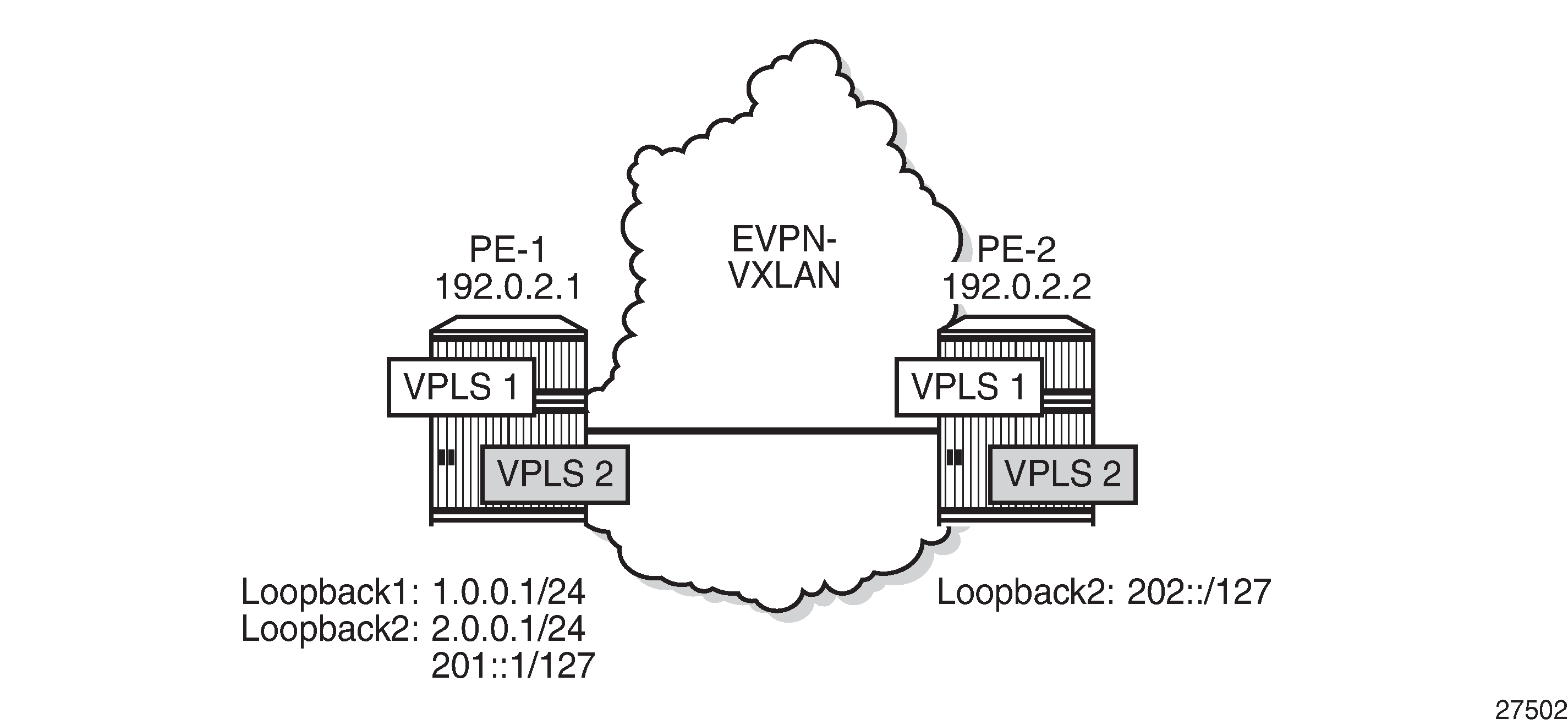
The initial configuration includes the cards, MDAs, ports, router interfaces and IGP. BGP is configured for address family EVPN, for example on PE-1 as follows:
# on PE-1:
configure
    router
        autonomous-system 64500
        bgp
            rapid-withdrawal
            split-horizon
            rapid-update evpn
            group "internal"
                family evpn
                peer-as 64500
                neighbor 192.0.2.2
                exit
            exit
        exit
In this example, the BGP peering is IPv4-based, but EVPN-VXLAN routes can also be exchanged between IPv6 BGP peers.
Non-system IP VXLAN termination
Create FPEs
PXC is used as a simple back-to-back cross-connect. An FPE uses the PXC ports assigned in the FPE path, either a PXC port or a LAG-based PXC. For non-system IP VXLAN terminations between VPLSs, the PXC is only required on the ingress (from VXLAN, or from PE-1 to GW PE-2). The following PXCs are created on PE-1:
# on PE-1:
configure
    port-xc
        pxc 1 create
            port 1/2/1
            no shutdown
        exit
        pxc 2 create
            port 1/2/2
            no shutdown
        exit
The PXC auto-created sub-ports and ports are enabled as follows.
# on PE-1:
configure
    port pxc-1.a
        no shutdown
    exit
    port pxc-1.b
        no shutdown
    exit
    port 1/2/1
        no shutdown
    exit
*A:PE-1# show port pxc 1

===============================================================================
Ports on Port Cross Connect 1
===============================================================================
Port          Admin Link Port    Cfg  Oper LAG/ Port Port Port   C/QS/S/XFP/
Id            State      State   MTU  MTU  Bndl Mode Encp Type   MDIMDX
-------------------------------------------------------------------------------
pxc-1.a       Up    Yes  Up      1574 1574    - hybr dotq xgige
pxc-1.b       Up    Yes  Up      1574 1574    - hybr dotq xgige
===============================================================================
The following FPEs use the PXCs.
# on PE-1, PE-2:
configure
    fwd-path-ext
        fpe 1 create
            path pxc 1
        exit
        fpe 2 create
            path pxc 2
        exit
These FPEs are created without defining a range of SDP IDs. SDP IDs are required in case of R-VPLS services terminating IPv6 VXLAN tunnels, where the FPE is also used at the egress and an internal static SDP is created to allow for the required extra processing.
When the FPE has no VXLAN termination associated, no internal router interfaces are created, so the only router interfaces are the system interface and the interface between PE-1 and PE-2, as follows.
*A:PE-1# show router interface

===============================================================================
Interface Table (Router: Base)
===============================================================================
Interface-Name                   Adm       Opr(v4/v6)  Mode    Port/SapId
   IP-Address                                                  PfxState
-------------------------------------------------------------------------------
int-PE-1-PE-2                    Up        Up/Down     Network 1/1/1
   192.168.12.1/30                                             n/a
system                           Up        Up/Down     Network system
   192.0.2.1/32                                                n/a
-------------------------------------------------------------------------------
Interfaces : 2
===============================================================================
Associate the FPEs with VXLAN termination
The following command associates the FPEs with VXLAN termination.
# on PE-1, PE-2:
configure
    fwd-path-ext
        sdp-id-range from 10000 to 10127
        fpe 1 create
            path pxc 1
            vxlan-termination
        exit
        fpe 2 create
            path pxc 2
            vxlan-termination
        exit
When attempting to associate the FPEs with VXLAN termination without configuring a range of SDP IDs for FPE, the following error is raised:
*A:PE-1>config>fwd-path-ext>fpe# vxlan-termination
MINOR: FPE #1021 sdp-id-range is not configured
After the FPEs are associated with VXLAN terminations, the system creates two internal router interfaces per FPE, one per PXC sub-port:
*A:PE-1# show router interface

===============================================================================
Interface Table (Router: Base)
===============================================================================
Interface-Name                   Adm       Opr(v4/v6)  Mode    Port/SapId
   IP-Address                                                  PfxState
-------------------------------------------------------------------------------
_tmnx_fpe_1.a                    Up        Up/Up       Network pxc-1.a:1
   fe80::100/64                                                PREFERRED
_tmnx_fpe_1.b                    Up        Up/Up       Network pxc-1.b:1
   fe80::101/64                                                PREFERRED
_tmnx_fpe_2.a                    Up        Up/Up       Network pxc-2.a:1
   fe80::200/64                                                PREFERRED
_tmnx_fpe_2.b                    Up        Up/Up       Network pxc-2.b:1
   fe80::201/64                                                PREFERRED
int-PE-1-PE-2                    Up        Up/Down     Network 1/1/1
   192.168.12.1/30                                             n/a
system                           Up        Up/Down     Network system
   192.0.2.1/32                                                n/a
-------------------------------------------------------------------------------
Interfaces : 6
===============================================================================
Configure router loopback interfaces
The following loopback interfaces are configured in PE-1 and added to the IS-IS context:
# on PE-1:
configure
    router Base
        interface "loopback1"
            address 1.0.0.1/24
            loopback
        exit
        interface "loopback2"
            address 2.0.0.1/31
            loopback
            ipv6
                address 201::/127
            exit
        exit
        isis
            interface "loopback1"
            exit
            interface "loopback2"
            exit
        exit
A non /32 or /128 subnet must be assigned to the loopback interface, because the system cannot terminate VXLAN on a local interface address. In the preceding example, all addresses in the subnet 1.0.0.0/24 can be used for VXLAN tunnel termination, except for 1.0.0.1. The subnet will be advertised by the IGP. The subnet can be as small as /31 or /127, as for example for interface "loopback2".
In this scenario, only one loopback interface with an IPv4 address is sufficient: interface "loopback1" with IPv4 address 1.0.0.1/24. There is no need to configure loopback interfaces in the GW PE-2, because VXLAN FPE is only required in the ingress (from VXLAN to GW).
Configure non-system VTEP addresses
Up to three non-system VTEP addresses can be configured to terminate VXLAN tunnels and their corresponding FPEs; on PE-1 as follows:
# on PE-1:
configure
    service
        system
            vxlan
                tunnel-termination 1.0.0.2 fpe 1 create
                tunnel-termination 2.0.0.2 fpe 2 create
                tunnel-termination 201::1 fpe 2 create
            exit
        exit
No non-system VTEP addresses need to be configured on PE-2.
When attempting to configure the IP address of the loopback interface as a VXLAN tunnel termination, the following error is raised:
*A:PE-1>config>service>system>vxlan# tunnel-termination 1.0.0.1 fpe 1 create
MINOR: SVCMGR #8353 VXLAN Tunnel termination IP address cannot be configured - IP address in use by another application or matches a local interface IP address
When attempting to configure more than three non-system VTEP addresses, the following error is raised:
*A:PE-1>config>service>system>vxlan# tunnel-termination 1.0.0.100 fpe 1 create
MINOR: SVCMGR #8353 VXLAN Tunnel termination IP address cannot be configured - Reached system limit of VXLAN tunnel-termination addresses
When the non-system VTEP addresses are configured, an internal loopback interface "_tmnx_vli_vxlan_1_131077" is created that can respond to ICMP requests.
*A:PE-1# show router interface

===============================================================================
Interface Table (Router: Base)
===============================================================================
Interface-Name                   Adm       Opr(v4/v6)  Mode    Port/SapId
   IP-Address                                                  PfxState
-------------------------------------------------------------------------------
_tmnx_fpe_1.a                    Up        Up/Up       Network pxc-1.a:1
   fe80::100/64                                                PREFERRED
_tmnx_fpe_1.b                    Up        Up/Up       Network pxc-1.b:1
   fe80::101/64                                                PREFERRED
_tmnx_fpe_2.a                    Up        Up/Up       Network pxc-2.a:1
   fe80::200/64                                                PREFERRED
_tmnx_fpe_2.b                    Up        Up/Up       Network pxc-2.b:1
   fe80::201/64                                                PREFERRED
_tmnx_vli_vxlan_1_131077         Up        Up/Up       Network loopback
   1.0.0.2/32                                                  n/a
   2.0.0.2/32                                                  n/a
   201::1/128                                                  PREFERRED
   fe80::f:ffff:fe00:0/64                                      PREFERRED
int-PE-1-PE-2                    Up        Up/Down     Network 1/1/1
   192.168.12.1/30                                             n/a
loopback1                        Up        Up/Down     Network loopback
   1.0.0.1/24                                                  n/a
loopback2                        Up        Up/Up       Network loopback
   2.0.0.1/31                                                  n/a
   201::/127                                                   PREFERRED
   fe80::f:ffff:fe00:0/64                                      PREFERRED
system                           Up        Up/Down     Network system
   192.0.2.1/32                                                n/a
-------------------------------------------------------------------------------
Interfaces : 9
===============================================================================
The system does not verify whether there is a local base router loopback interface with a subnet corresponding to the VTEP address. If a tunnel termination address is configured and the FPE is up, the system will start terminating VXLAN traffic and responding using ICMP for that address, regardless of the presence of a loopback interface in the base router. It is also possible that a non-loopback interface has an IP address in the configured subnet.
Configure the VPLS
A VPLS will be configured with EVPN-VXLAN enabled. By default, the system IP address will be used as the source VTEP of the VXLAN-encapsulated frames. This default behavior can be overruled by the vxlan-src-vtep command in the VPLS. The IP address corresponds to the non-system VTEP address configured in the preceding step (VXLAN tunnel termination). VPLS 1 is configured on PE-1 as follows:
# on PE-1:
configure
    service
        vpls 1 name "EVI-1" customer 1 create
            vxlan instance 1 vni 1 create
            exit
            vxlan-src-vtep 1.0.0.2
            bgp
            exit
            bgp-evpn
                evi 1
                vxlan bgp 1 vxlan-instance 1
                    no shutdown
                exit
            exit
            stp
                shutdown
            exit
            sap 1/1/2:1 create
                no shutdown
            exit
            no shutdown
        exit
When attempting to configure an IP address different from the VTEP addresses, the following error is raised:
*A:PE-1# configure service vpls 1 vxlan-src-vtep 1.0.0.99
MINOR: SVCMGR #8351 VXLAN Tunnel termination IP address does not exist
A different VTEP address can be configured as vxlan-src-vtep in different services on the same PE, as follows:
# on PE-1:
configure
    service
        vpls 2 name "EVI-2" customer 1 create
            allow-ip-int-bind
            exit
            vxlan instance 1 vni 2 create
            exit
            vxlan-src-vtep 201::1
            bgp
            exit
            bgp-evpn
                evi 2
                vxlan bgp 1 vxlan-instance 1
                    no shutdown
                exit
            exit
            stp
                shutdown
            exit
            no shutdown
        exit
The configuration of VPLS 1 on PE-2 does not include any VTEP address, because it is not required in the egress, as follows:
# on PE-2:
configure
    service
        vpls 1 name "VPLS 1" customer 1 create
            vxlan instance 1 vni 1 create
            exit
            bgp
            exit
            bgp-evpn
                evi 1
                vxlan bgp 1 vxlan-instance 1
                    no shutdown
                exit
            exit
            stp
                shutdown
            exit
            no shutdown
        exit
When a vxlan-src-vtep is configured in VPLS 1 on PE-1, this VTEP address will be used as the IP source VTEP for VPLS 1 and BGP will use this VTEP to the BGP NLRI next-hop, as shown in the following BGP route update messages.
The following BGP EVPN inclusive multicast route sent by PE-1 shows the configured source VTEP address 1.0.0.2 as NLRI next-hop, as originator address, and as tunnel endpoint.
# on PE-1:
1 2021/05/06 09:40:06.914 UTC MINOR: DEBUG #2001 Base Peer 1: 192.0.2.2
"Peer 1: 192.0.2.2: UPDATE
Peer 1: 192.0.2.2 - Send BGP UPDATE:
    Withdrawn Length = 0
    Total Path Attr Length = 77
    Flag: 0x90 Type: 14 Len: 28 Multiprotocol Reachable NLRI:
        Address Family EVPN
        NextHop len 4 NextHop 1.0.0.2
        Type: EVPN-INCL-MCAST Len: 17 RD: 192.0.2.1:1, tag: 0, orig_addr len: 32,
                              orig_addr: 1.0.0.2
    Flag: 0x40 Type: 1 Len: 1 Origin: 0
    Flag: 0x40 Type: 2 Len: 0 AS Path:
    Flag: 0x40 Type: 5 Len: 4 Local Preference: 100
    Flag: 0xc0 Type: 16 Len: 16 Extended Community:
        target:64500:1
        bgp-tunnel-encap:VXLAN
    Flag: 0xc0 Type: 22 Len: 9 PMSI:
        Tunnel-type Ingress Replication (6)
        Flags: (0x0)[Type: None BM: 0 U: 0 Leaf: not required]
        MPLS Label 1
        Tunnel-Endpoint 1.0.0.2
"
The following BGP EVPN-MAC route sent by PE-1 shows the configured VTEP for VPLS 1 as NLRI next-hop:
# on PE-1:
8 2021/05/06 09:41:43.212 UTC MINOR: DEBUG #2001 Base Peer 1: 192.0.2.2
"Peer 1: 192.0.2.2: UPDATE
Peer 1: 192.0.2.2 - Send BGP UPDATE:
    Withdrawn Length = 0
    Total Path Attr Length = 81
    Flag: 0x90 Type: 14 Len: 44 Multiprotocol Reachable NLRI:
        Address Family EVPN
        NextHop len 4 NextHop 1.0.0.2
        Type: EVPN-MAC Len: 33 RD: 192.0.2.1:1 ESI: ESI-0, tag: 0, mac len: 48
                       mac: ca:fe:01:10:10:10, IP len: 0, IP: NULL, label1: 1
    Flag: 0x40 Type: 1 Len: 1 Origin: 0
    Flag: 0x40 Type: 2 Len: 0 AS Path:
    Flag: 0x40 Type: 5 Len: 4 Local Preference: 100
    Flag: 0xc0 Type: 16 Len: 16 Extended Community:
        target:64500:1
        bgp-tunnel-encap:VXLAN
"
A BGP peer policy might override the NLRI next-hop created due to the vxlan-src-vtep configuration.
The following shows that the source VTEP address on PE-1 is 1.0.0.2:
*A:PE-1# show service id 1 vxlan
===============================================================================
VPLS VXLAN
===============================================================================
Vxlan Src Vtep IP: 1.0.0.2

===============================================================================
Vxlan Instance
===============================================================================
VXLAN Instance                VNI         AR          Oper-flags   VTEP
                                                                   security
-------------------------------------------------------------------------------
1                             1           none        none         disabled
-------------------------------------------------------------------------------
Number of Entries : 1
-------------------------------------------------------------------------------
===============================================================================
The following command on PE-1 shows that the egress VTEP is 192.0.2.2:
*A:PE-1# show service id 1 vxlan destinations

===============================================================================
Egress VTEP, VNI
===============================================================================
Instance    VTEP Address                            Egress VNI  EvpnStatic Num
 Mcast       Oper State                              L2 PBR     SupBcasDom MACs
-------------------------------------------------------------------------------
1           192.0.2.2                               1           evpn       0
 BUM         Up                                      No          No
-------------------------------------------------------------------------------
Number of Egress VTEP, VNI : 1
-------------------------------------------------------------------------------
===============================================================================

===============================================================================
BGP EVPN-VXLAN Ethernet Segment Dest
===============================================================================
Instance  Eth SegId                       Num. Macs     Last Change
-------------------------------------------------------------------------------
No Matching Entries
===============================================================================
The following shows that no source VTEP address is configured on PE-2:
*A:PE-2# show service id 1 vxlan
===============================================================================
VPLS VXLAN
===============================================================================
Vxlan Src Vtep IP: N/A

===============================================================================
Vxlan Instance
===============================================================================
VXLAN Instance                VNI         AR          Oper-flags   VTEP
                                                                   security
-------------------------------------------------------------------------------
1                             1           none        none         disabled
-------------------------------------------------------------------------------
Number of Entries : 1
-------------------------------------------------------------------------------
===============================================================================
The following command on PE-2 shows that the egress VTEP is 1.0.0.2:
*A:PE-2# show service id 1 vxlan destinations

===============================================================================
Egress VTEP, VNI
===============================================================================
Instance    VTEP Address                            Egress VNI  EvpnStatic Num
 Mcast       Oper State                              L2 PBR     SupBcasDom MACs
-------------------------------------------------------------------------------
1           1.0.0.2                                 1           evpn       1
 BUM         Up                                      No          No
-------------------------------------------------------------------------------
Number of Egress VTEP, VNI : 1
-------------------------------------------------------------------------------
===============================================================================

===============================================================================
BGP EVPN-VXLAN Ethernet Segment Dest
===============================================================================
Instance  Eth SegId                       Num. Macs     Last Change
-------------------------------------------------------------------------------
No Matching Entries
===============================================================================
Underlay IPv6 VXLAN termination
The configuration for underlay IPv6 VXLAN termination is similar to the non-system IP VXLAN termination. In the following example, R-VPLS 2 is configured; therefore, non-system VTEP addresses are configured in PE-2 as well as in PE-1. The changes required in PE-1 are as follows.
IPv6 must be enabled on the router interfaces
IPv6 native routing is configured in IS-IS
IPv6 addresses are loopback address 201::/127 and VTEP address 201::1
# on PE-1:
configure
    port-xc
        pxc 2 create
            port 1/2/2
            no shutdown
        exit
    exit
    port pxc-2.a
        no shutdown
    exit
    port pxc-2.b
        no shutdown
    exit
    port 1/2/2
        no shutdown
    exit
    fwd-path-ext
        sdp-id-range from 10000 to 10127
        fpe 2 create
            path pxc 2
            vxlan-termination
        exit
    exit
    router Base
        interface "int-PE-1-PE-2
            address 192.168.12.1/30
            port 1/1/1
            ipv6
            exit
        exit
        interface "loopback2"
            address 2.0.0.1/31
            loopback
            ipv6
                address 201::/127
            exit
        exit
        isis 0
            ipv6-routing native
            interface "loopback2"
            exit
        exit
    exit
    service
        system
            vxlan
                tunnel-termination 201::1 fpe 2 create
            exit
        exit
        vpls 2 name "EVI-2" customer 1 create
            allow-ip-int-bind
            exit
            vxlan instance 1 vni 2 create
            exit
            vxlan-src-vtep 201::1
            bgp
            exit
            bgp-evpn
                evi 2
                vxlan bgp 1 vxlan-instance 1
                    no shutdown
                exit
            exit
            stp
                shutdown
            exit
            no shutdown
        exit
The service configuration on PE-2 is as follows.
# on PE-2:
configure
    service
        system
            vxlan
                tunnel-termination 202:: fpe 2 create
            exit
        exit
        vpls 2 name "EVI-2" customer 1 create
            allow-ip-int-bind
            exit
            vxlan instance 1 vni 2 create
            exit
            vxlan-src-vtep 202::
            bgp
            exit
            bgp-evpn
                evi 2
                vxlan bgp 1 vxlan-instance 1
                    no shutdown
                exit
            exit
            stp
                shutdown
            exit
            no shutdown
        exit
The routing table for IPv6 on PE-1 shows that an internal static route is configured for the source VTEP 201::1 using the FPE internal interface "_tmnx_fpe_2.a". The route to egress VTEP 202:: is an IS-IS route.
*A:PE-1# show router route-table ipv6

===============================================================================
IPv6 Route Table (Router: Base)
===============================================================================
Dest Prefix[Flags]                            Type    Proto     Age        Pref
      Next Hop[Interface Name]                                    Metric
-------------------------------------------------------------------------------
201::/127                                     Local   Local     00h16m34s  0
       loopback2                                                    0
201::1/128                                    Remote  Static    00h11m53s  5
       fe80::201-"_tmnx_fpe_2.a"                                    1
202::/127                                     Remote  ISIS      00h00m06s  15
       fe80::14:1ff:fe01:1-"int-PE-1-PE-2"                          10
-------------------------------------------------------------------------------
No. of Routes: 3
Likewise, the routing table for IPv6 on PE-2 shows an internal static route for source VTEP 202:: using the FPE internal interface "_tmnx_fpe_2.a":
*A:PE-2# show router route-table ipv6

===============================================================================
IPv6 Route Table (Router: Base)
===============================================================================
Dest Prefix[Flags]                            Type    Proto     Age        Pref
      Next Hop[Interface Name]                                    Metric
-------------------------------------------------------------------------------
201::/127                                     Remote  ISIS      00h00m06s  15
       fe80::10:1ff:fe01:1-"int-PE-2-PE-1"                          10
202::/127                                     Local   Local     00h00m12s  0
       loopback2                                                    0
202::/128                                     Remote  Static    00h00m13s  5
       fe80::201-"_tmnx_fpe_2.a"                                    1
-------------------------------------------------------------------------------
No. of Routes: 3
When non-system IPv6 VTEP addresses are used in an R-VPLS, VTEP addresses need to be configured on ingress and egress VXLAN. The system creates an internal SDP binding for the egress processing. A range of SDP IDs has been configured from 10000 to 10127. The following command lists all SDP bindings for FPE:
*A:PE-2# show service sdp-using | match "Fpe"
2          10002:2            Fpe    fpe_2.b              Up    524286  524286
The internal SDP has ID 10002 and the far-end is fpe_2.b. The following command shows that the SDP source is FPE.
*A:PE-2# show service sdp 10002 detail | match "Sdp" pre-lines 4 post-lines 10

===============================================================================
Service Destination Point (Sdp Id : 10002) Details
===============================================================================
-------------------------------------------------------------------------------
 Sdp Id 10002  -fpe_2.b
-------------------------------------------------------------------------------
Description           : (Not Specified)
SDP Id               : 10002                 SDP Source         : fpe
Admin Path MTU       : 0                     Oper Path MTU      : 1552
Delivery             : MPLS
Far End              : fpe_2.b               Tunnel Far End     : n/a
Oper Tunnel Far End  : n/a
LSP Types            : FPE

Admin State          : Up                    Oper State         : Up
The following command on PE-1 shows that the source VTEP is 201::1:
*A:PE-1# show service id 2 vxlan
===============================================================================
VPLS VXLAN
===============================================================================
Vxlan Src Vtep IP: 201::1

===============================================================================
Vxlan Instance
===============================================================================
VXLAN Instance                VNI         AR          Oper-flags   VTEP
                                                                   security
-------------------------------------------------------------------------------
1                             2           none        none         disabled
-------------------------------------------------------------------------------
Number of Entries : 1
-------------------------------------------------------------------------------
===============================================================================
The following command on PE-1 shows that the egress VTEP is 202::.
*A:PE-1# show service id 2 vxlan destinations

===============================================================================
Egress VTEP, VNI
===============================================================================
Instance    VTEP Address                            Egress VNI  EvpnStatic Num
 Mcast       Oper State                              L2 PBR     SupBcasDom MACs
-------------------------------------------------------------------------------
1           202::                                   2           evpn       0
 BUM         Up                                      No          No
-------------------------------------------------------------------------------
Number of Egress VTEP, VNI : 1
-------------------------------------------------------------------------------
===============================================================================

===============================================================================
BGP EVPN-VXLAN Ethernet Segment Dest
===============================================================================
Instance  Eth SegId                       Num. Macs     Last Change
-------------------------------------------------------------------------------
No Matching Entries
===============================================================================
The following command on PE-2 shows that the source VTEP is 202::.
*A:PE-2# show service id 2 vxlan
===============================================================================
VPLS VXLAN
===============================================================================
Vxlan Src Vtep IP: 202::

===============================================================================
Vxlan Instance
===============================================================================
VXLAN Instance                VNI         AR          Oper-flags   VTEP
                                                                   security
-------------------------------------------------------------------------------
1                             2           none        none         disabled
-------------------------------------------------------------------------------
Number of Entries : 1
-------------------------------------------------------------------------------
===============================================================================
The following command on PE-2 shows that the egress VTEP is 201::1.
*A:PE-2# show service id 2 vxlan destinations

===============================================================================
Egress VTEP, VNI
===============================================================================
Instance    VTEP Address                            Egress VNI  EvpnStatic Num
 Mcast       Oper State                              L2 PBR     SupBcasDom MACs
-------------------------------------------------------------------------------
1           201::1                                  2           evpn       0
 BUM         Up                                      No          No
-------------------------------------------------------------------------------
Number of Egress VTEP, VNI : 1
-------------------------------------------------------------------------------
===============================================================================

===============================================================================
BGP EVPN-VXLAN Ethernet Segment Dest
===============================================================================
Instance  Eth SegId                       Num. Macs     Last Change
-------------------------------------------------------------------------------
No Matching Entries
===============================================================================
Conclusion
VXLAN FPE is required to terminate VXLAN tunnels on non-system IPv4/IPv6 addresses and to configure IPv6 underlay.