BGP Multi-Homing for VPLS Networks
This chapter describes BGP Multi-Homing (BGP-MH) for VPLS network configurations.
Topics in this chapter include:
Applicability
Initially, the information in this chapter was based on SR OS Release 8.0.R5, with additions for SR OS Release 9.0.R1. The CLI in the current edition corresponds to SR OS Release 20.10.R2.
Overview
SR OS supports the use of Border Gateway Protocol Multi-Homing for VPLS (hereafter called BGP-MH). BGP-MH is described in draft-ietf-bess-vpls-multihoming, BGP based Multi-homing in Virtual Private LAN Service, and provides a network-based resiliency mechanism (no interaction from the Provider Edge routers (PEs) to Multi-Tenant Units/Customer Equipment (MTU/CE)) that can be applied on service access points (SAPs) or network (pseudowires) topologies. The BGP-MH procedures will run between the PEs and will provide a loop-free topology from the network perspective (only one logical active path will be provided per VPLS among all the objects SAPs or pseudowires which are part of the same Multi-Homing site).
Each multi-homing site connected to two or more peers is represented by a site ID (2 bytes long) which is encoded in the BGP MH Network Layer Reachability Information (NLRI). The BGP peer holding the active path for a particular multi-homing site will be named as the Designated Forwarder (DF), whereas the rest of the BGP peers participating in the BGP MH process for that site will be named as non-DF and will block the traffic (in both directions) for all the objects belonging to that multi-homing site.
BGP MH uses the following rules to determine which PE is the DF for a particular multi-homing site:
A BGP MH NLRI with D flag = 0 (multi-homing object up) always takes precedence over a BGP MH NLRI with D flag = 1 (multi-homing object down). If there is a tie, then:
The BGP MH NLRI with the highest BGP Local Preference (LP) wins. If there is a tie, then:
The BGP MH NLRI issued from the PE with the lowest PE ID (system address) wins.
The main advantages of using BGP-MH as opposed to other resiliency mechanisms for VPLS are:
Flexibility: BGP-MH uses a common mechanism for access and core resiliency. The designer has the flexibility of using BGP-MH to control the active/standby status of SAPs, spoke SDPs, Split Horizon Groups (SHGs) or even mesh SDP bindings.
The standard protocol is based on BGP, a standard, scalable, and well-known protocol.
Specific benefits at the access:
It is network-based, independent of the customer CE and, as such, it does not need any customer interaction to determine the active path. Consequently, the operator will spend less effort on provisioning and will minimize both operation costs and security risks (in particular, this removes the requirement for spanning tree interaction between the PE and CE).
Easy load balancing per service (no service fate-sharing) on physical links.
Specific benefits in the core:
It is a network-based mechanism, independent of the MTU resiliency capabilities and it does not need MTU interaction, therefore operational advantages are achieved as a result of the use of BGP-MH: less provisioning is required and there will be minimal risks of loops. In addition, simpler MTUs can be used.
Easy load balancing per service (no service fate-sharing) on physical links.
Less control plane overhead: there is no need for an additional protocol running the pseudowire redundancy when BGP is already used in the core of the network. BGP-MH just adds a separate NLRI in the L2-VPN family (AFI=25, SAFI=65).
This chapter describes how to configure and troubleshoot BGP-MH for VPLS.
Knowledge of the LDP/BGP VPLS (RFC 4762, Virtual Private LAN Service (VPLS) Using Label Distribution Protocol (LDP) Signaling, and RFC 4761, Virtual Private LAN Service (VPLS) Using BGP for Auto-Discovery and Signaling) architecture and functionality is assumed throughout this document. For further information, see the relevant Nokia documentation.
Example topology shows the example topology that will be used throughout the rest of the chapter.
The initial configuration includes:
-
IGP — IS-IS, Level 2 on all routers; area 49.0001
-
RSVP-TE for transport tunnels
-
Fast reroute (FRR) protection in the core; no FRR protection at the access.
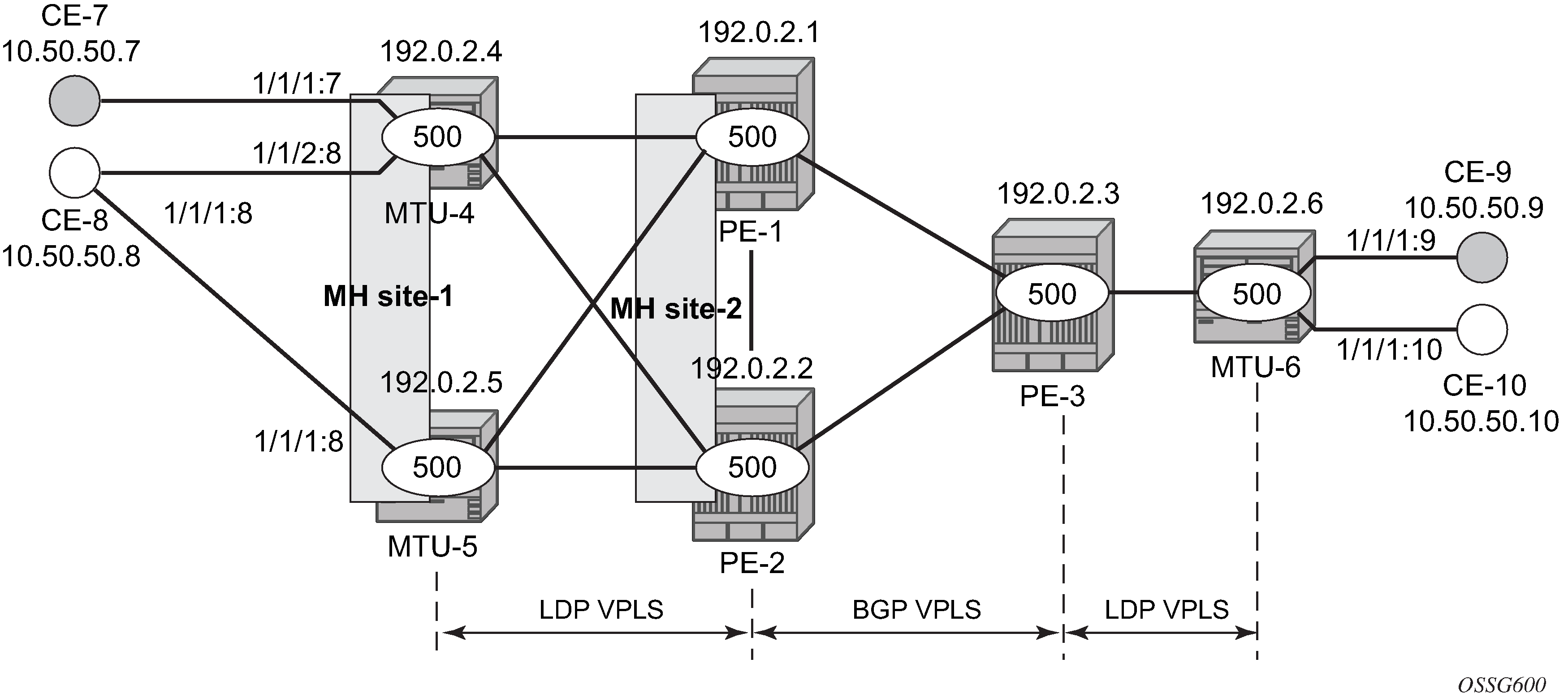
The topology consists of three core nodes (PE-1, PE-2, and PE-3) and three MTUs connected to the core.
The VPLS service 500 is configured on all the six nodes with the following characteristics:
-
The core VPLS instances are connected by a full mesh of BGP-signaled pseudowires (that is, pseudowires among PE-1, PE-2, and PE-3 will be signaled by BGP VPLS).
-
As shown in Example topology, the MTUs are connected to the BGP VPLS core by TLDP pseudowires. MTU-6 is connected to PE-3 by a single pseudowire, whereas MTU-4 and MTU-5 are dual-homed to PE-1 and PE-2. The following resiliency mechanisms are used on the dual-homed MTUs:
-
MTU-4 is dual-connected to PE-1 and PE-2 by an active/standby pseudowire (A/S pseudowire hereafter).
-
MTU-5 is dual-connected to PE-1 and PE-2 by two active pseudowires, one of them being blocked by BGP MH running between PE-1 and PE-2. The PE-1 and PE-2 pseudowires, set up from MTU-5, will be part of the BGP MH site MH-site-2.
-
MTU-4 and MTU-5 are running BGP MH, being SHG site-1 and SAP 1/1/1:8 on MTU-5 part of the same BGP MH site, MH-site-1.
-
-
The CEs are connected to the network in the following way:
-
CE-7, CE-9, and CE-10 are single-connected to the network
-
CE-8 is dual connected to MTU-4 and MTU-5.
-
CE-7 and CE-8 are part of the split-horizon group (SHG) site-1(SAPs 1/1/4:500 and 1/1/3:500 on MTU-4). Assume that CE-7 and CE-8 have a backdoor link between them so that when MTU-5 is elected as DF, CE-7 does not get isolated. This configuration highlights the use of a SHG within a site configuration.
-
For each BGP MH site, MH-site-1 and MH-site-2, the BGP MH process will elect a DF, blocking the site objects for the non-DF nodes. In other words, based on the specific configuration explained throughout the chapter:
-
For MH-site-1, MTU-4 will be elected as the DF. The non-DF-MTU-5 will block the SAP 1/1/1:8.
-
For MH-site-2, PE-1 will be elected as the DF. The non-DF PE-1 will block the spoke-SDP to MTU-5.
Configuration
This section describes all the relevant configuration tasks for the setup shown in Example topology. The appropriate associated IP/MPLS configuration is out of the scope of this chapter. In this example, the following protocols will be configured beforehand:
ISIS-TE as IGP with all the interfaces being level-2 (OSPF-TE could have been used instead).
RSVP-TE as the MPLS protocol to signal the transport tunnels (LDP could have been used instead).
LSPs between core PEs will be FRR protected (facility bypass tunnels) whereas LSP tunnels between MTUs and PEs will not be protected.
Note:The designer can choose whether to protect access link failures by means of MPLS FRR or A/S pseudowire or BGP MH. Whereas FRR provides a faster convergence (around 50ms) and stability (it does not impact on the service layer, therefore, link failures do not trigger MAC flush and flooding), some interim inefficiencies can be introduced compared to A/S pseudowire or BGP MH.
Once the IP/MPLS infrastructure is up and running, the specific service configuration including the support for BGP MH can begin.
Global BGP configuration
BGP is used in this configuration guide for these purposes:
Auto-discovery and signaling of the pseudowires in the core, as per RFC 4761.
Exchange of multi-homing site NLRIs and redundancy handling from MTU-5 to the core.
Exchange of multi-homing site NLRIs and redundancy handling at the access for CE-7/CE-8.
A BGP route reflector (RR), PE-3, is used for the reflection of BGP updates corresponding to the preceding uses a and b.
A direct peering is established between MTU-4 and MTU-5 for use c. The same RR could have been used for the three cases, however, like in this example, the designer may choose to have a direct BGP peering between access devices. The reasons for this are:
By having a direct BGP peering between MTU-4 and MTU-5, the BGP updates do not have to travel back and forth.
On MTU-4 and MTU-5, BGP is exclusively used for multi-homing, therefore there will not be more BGP peers for either MTUs and a RR adds nothing in terms of control plane scalability.
On all nodes, the autonomous system number must be configured.
# on all nodes:
configure
    router Base
        autonomous-system 65000
The following CLI output shows the global BGP configuration required on MTU-4. The 192.0.2.5 address will be replaced by the corresponding peer or the RR system address for PE-1 and PE-2.
# on MTU-4:
configure
    router Base
        bgp
            family l2-vpn
            rapid-withdrawal
            rapid-update l2-vpn
            group "Multi-Homing"
                neighbor 192.0.2.5
                    peer-as 65000
                exit
            exit
In this example, PE-3 is the BGP RR, therefore its BGP configuration will contain a cluster with all its peers included (PE-1 and PE-2):
# on PE-3:
configure
    router Base
        bgp
            family l2-vpn
            rapid-withdrawal
            rapid-update l2-vpn
            group "internal"
                cluster 1.1.1.1
                neighbor 192.0.2.1
                    peer-as 65000
                exit
                neighbor 192.0.2.2
                    peer-as 65000
                exit
            exit
The relevant BGP commands for BGP-MH are in bold. Some considerations about those:
It is required to specify family l2-vpn in the BGP configuration. That statement will allow the BGP peers to agree on the support for the family AFI=25 (Layer 2 VPN), SAFI=65 (VPLS). This family is used for BGP VPLS as well as for BGP MH and BGP AD.
The rapid-update l2-vpn statement allows BGP MH to send BGP updates immediately after detecting link failures, without having to wait for the Minimum Route Advertisement Interval (MRAI) to send the updates in batches. This statement is required to guarantee a fast convergence for BGP MH.
Optionally, rapid-withdrawal can also be added. In the context of BGP MH, this command is only useful if a particular multi-homing site is cleared. In that case, a BGP withdrawal is sent immediately without having to wait for the MRAI. A multi-homing site is cleared when the BGP MH site is removed or even the entire VPLS service.
Service level configuration
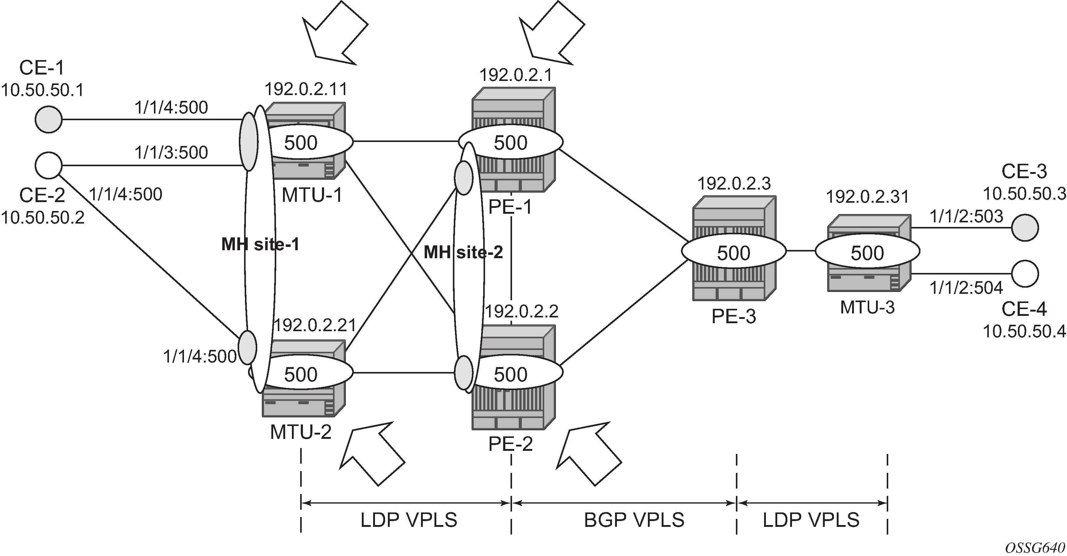
Once the IP/MPLS infrastructure is configured, including BGP, this section shows the configuration required at service level (VPLS 500). The focus is on the nodes involved on BGP MH, that is, MTU-4, MTU-5, PE-1, and PE-2. These nodes are highlighted in Nodes involved in BGP MH.
Core PE service configuration
The following CLI excerpt shows the service level configuration on PE-1. The import/export policies configured on the PE nodes are identical:
# on PE-1:
configure
    router Base
        policy-options
            begin
            community "comm_core"
                members "target:65000:500"
            exit
            policy-statement "vsi500_export"
                entry 10
                    action accept
                        community add "comm_core"
                    exit
                exit
            exit
            policy-statement "vsi500_import"
                entry 10
                    from
                        community "comm_core"
                        family l2-vpn
                    exit
                    action accept
                    exit
                exit
                default-action drop
                exit
            exit
            commit
The configuration of the SDPs, PW template, and VPLS on PE-1 is as follows:
# on PE-1:
configure
    service
        sdp 12 mpls create
            description "SDP to transport BGP-signaled PWs"
            signaling bgp
            far-end 192.0.2.2
            lsp "LSP-PE-1-PE-2"
            path-mtu 8000
            no shutdown
        exit
        sdp 13 mpls create
            description "SDP to transport BGP-signaled PWs"
            signaling bgp
            far-end 192.0.2.3
            lsp "LSP-PE-1-PE-3"
            path-mtu 8000
            no shutdown
        exit
        sdp 14 mpls create
            far-end 192.0.2.4
            lsp "LSP-PE-1-MTU-4"
            path-mtu 8000
            no shutdown
        exit
        sdp 15 mpls create
            far-end 192.0.2.5
            lsp "LSP-PE-1-MTU-5"
            path-mtu 8000
            no shutdown
        exit
        pw-template 500 use-provisioned-sdp create
        exit
        vpls 500 name "VLPS 500" customer 1 create
            bgp
                route-distinguisher 65000:501
                vsi-export "vsi500_export"
                vsi-import "vsi500_import"
                pw-template-binding 500 split-horizon-group "CORE"
                exit
            exit
            bgp-vpls
                max-ve-id 65535
                ve-name 501
                    ve-id 501
                exit
                no shutdown
            exit
            site "MH-site-2" create
                site-id 2
                spoke-sdp 15:500
                no shutdown
            exit
            spoke-sdp 14:500 create
            exit
            spoke-sdp 15:500 create
            exit
            no shutdown
        exit
The following are general comments about the configuration of VPLS 500:
As seen in the preceding CLI output for PE-1, there are four provisioned SDPs that the service VPLS 500 will use in this example. SDP 14 and SDP 15 are tunnels over which the TLDP FEC128 pseudowires for service 500 will be carried (according to RFC 4762), whereas SDP 12 and SDP 13 are the tunnels for the core BGP pseudowires (based on RFC 4761).
The BGP context provides the general service BGP configuration that will be used by BGP VPLS and BGP MH:
Route distinguisher (notation chosen is based on <AS_number:500 + node_id>)
VSI export policies are used to add the export route-targets included in all the BGP updates sent to the BGP peers.
VSI import policies are used to control the NLRIs accepted in the RIB, normally based on the route targets.
Both VSI-export and VSI-import policies can be used to modify attributes such as the Local Preference (LP) that will be used to influence the BGP MH Designated Forwarder (DF) election (LP is the second rule in the BGP MH election process, as previously discussed). The use of these policies will be described later in the chapter.
The pw-template-binding command maps the previously defined pw-template 500 to the SHG ‟CORE”. In this way, all the BGP-signaled pseudowires will be part of this SHG. Although not shown in this example, the pw-template-binding command can also be used to instantiate pseudowires within different SHGs, based on different import route targets:
Note:Detailed BGP-VPLS configuration is out of the scope of this chapter. For more information, see chapter BGP-VPLS.
*A:PE-1# configure service vpls 500 bgp pw-template-binding ?
  - pw-template-binding <policy-id> [split-horizon-group <group-name>]
                                      [import-rt {ext-community,...(upto 5 max)}]
  - no pw-template-binding <policy-id>

---snip---
The BGP-signaled pseudowires (from PE-1 to PE-2 and PE-3) are set up according to the configuration in the bgp context. Beside those pseudowires, the VPLS 500 also has two more pseudowires signaled by TLDP: spoke-SDP 14:500 (to MTU-4) and spoke-SDP 15:500 (to MTU-5).
The general BGP MH configuration parameters for a particular multi-homing site are shown in the following output:
*A:PE-1# configure service vpls ?
  - no vpls <service-id>
  - vpls <service-id> [customer <customer-id>] [create] [vpn <vpn-id>] [m-vpls]
                                             [b-vpls|i-vpls] [etree] [name <name>]

---snip---
*A:PE-1# configure service vpls 500 site ?
  - no site <name>
  - site <name> [create]

 <name>               : [32 chars max]

 [no] boot-timer      - Configure/Override site boot-timer
      failed-thresho* - Configure threshold for the site to be declared down
 [no] mesh-sdp-bindi* - Enable/Disable application to all Mesh-SDP
 [no] monitor-oper-g* - Configure an Operational-Group to monitor
 [no] sap             - Configure a SAP for the site
 [no] shutdown        - Administratively enable/disable the site
 [no] site-activatio* - Configure/Override site activation timer
 [no] site-id         - Configure site identifier
 [no] site-min-down-* - Configure minimum down timer for the site
 [no] split-horizon-* - Configure a split-horizon-group
 [no] spoke-sdp       - Configure a spoke-SDP
Where:
The site name is defined by a string of up to 32 characters.
The site-id is an integer that identifies the multi-homing site and is encoded in the BGP MH NLRI. This ID must be the same one used on the peer node where the same multi-homing site is connected to. That is, MH-site-2 must use the same site-id in PE-1 and PE-2 (value = 2 in the PE-1 site configuration).
Out of the four potential objects in a site—spoke SDP, SAP, SHG, and mesh SDP binding—only one can be used at the time on a particular site. To add more than just one SAP/spoke-SDP to the same site, an SHG composed of the SAP/spoke-SDP objects must be used in the site configuration. Otherwise, only one object—spoke SDP, SAP, SHG, or mesh SDP binding—is allowed per site. A CLI log message warns the operator of such fact:
*A:PE-1>config>service>vpls>site# mesh-sdp-binding
MINOR: SVCMGR #5855 only one object is allowed per site
The failed-threshold command defines how many objects should be down for the site to be declared down. This command is obviously only valid for multi-object sites (SHGs and mesh-SDP bindings). By default, all the objects in a site must be down for the site to be declared as operationally down.
*A:PE-1>config>service>vpls>site# failed-threshold ?
  - failed-threshold <[1..1000]>
  - failed-threshold all
The boot-timer specifies for how long the service manager waits after a node reboot before running the MH procedures. The boot-timer value should be configured to allow for the BGP sessions to come up and for the NLRI information to be refreshed/exchanged. In environments with the default BGP MRAI (30 seconds), it is highly recommended to increase this value (for instance, 120 seconds for a normal configuration). The boot-timer is only important when a node comes back up and would become the DF. Default value: 10 seconds.
*A:PE-1>config>service>vpls>site# boot-timer ?
  - boot-timer <seconds>
  - no boot-timer

 <seconds>            : [0..600]
The site-activation-timer command defines the amount of time the service manager will keep the local objects in standby (in the absence of BGP updates from remote PEs) before running the DF election algorithm to decide whether the site should be unblocked. The timer is started when one of the following events occurs only if the site is operationally up:
Manual site activation using the no shutdown command at the site-id level or at member object(s) level (SAP(s) or pseudowire(s))
Site activation after a failure
The BGP MH election procedures will be resumed upon expiration of this timer or the arrival of a BGP MH update for the multi-homing site. Default value: 2 seconds.
*A:PE-1>config>service>vpls>site# site-activation-timer ?
  - no site-activation-timer
  - site-activation-timer <seconds>

 <seconds>            : [0..100]
When a BGP MH site goes down, it may be preferred that it stays down for a minimum time. This is configurable by the site-min-down-timer. When set to zero, this timer is disabled.
*A:PE-1>config>service>vpls>site# site-min-down-timer ?
  - no site-min-down-timer
  - site-min-down-timer <seconds>

 <seconds>            : [0..100]
The boot-timer, site-activation-timer, and site-min-down-timer commands can be provisioned at service level or at global level. The service level settings have precedence and override the global configuration. The no form of the commands at global level, sets the value back to the default values. The no form of the commands at service level, makes the timers inherit the global values.
*A:PE-1# configure redundancy bgp-multi-homing ?
  - bgp-multi-homing

 [no] boot-timer      - Configure BGP multi-homing boot-timer
 [no] site-activatio* - Configure BGP multi-homing site activation timer
 [no] site-min-down-* - Configure minimum down timer for the site
The shutdown command controls the admin state of the site. Each site has three possible states:
Admin state — controlled by the shutdown command.
Operational state — controlled by the operational status of the individual site objects.
Designated Forwarder (DF) state — controlled by the BGP MH election algorithm.
The following CLI output shows the three states for BGP MH site ‟MH-site-1” on MTU-5:
*A:MTU-5# show service id 500 site "MH-site-1"

===============================================================================
Site Information
===============================================================================
Site Name            : MH-site-1
-------------------------------------------------------------------------------
Site Id              : 1
Dest                 : sap:1/1/1:8          Mesh-SDP Bind    : no
Admin Status         : Enabled              Oper Status      : up
Designated Fwdr      : No
DF UpTime            : 0d 00:00:00          DF Chg Cnt       : 1
Boot Timer           : default              Timer Remaining  : 0d 00:00:00
Site Activation Timer: default              Timer Remaining  : 0d 00:00:00
Min Down Timer       : default              Timer Remaining  : 0d 00:00:00
Failed Threshold     : default(all)
Monitor Oper Grp     : (none)
===============================================================================
For this example, MH-site ‟ MH-site-2” is configured in PE-1, where the site-id is 2 and the object in the site is spoke-SDP 15:500 (pseudowire established from PE-1 to MTU-5).
The following CLI shows the service configuration for PE-2. The site-id is 2, that is, the same value configured in PE-1. The object defined in PE-2’s site is spoke-SDP 25:500 (pseudowire established from PE-2 to MTU-5).
# on PE-2:
configure
    service
        sdp 21 mpls create
            description "SDP to transport BGP-signaled PWs"
            signaling bgp
            far-end 192.0.2.1
            lsp "LSP-PE-2-PE-1"
            path-mtu 8000
            no shutdown
        exit
        sdp 23 mpls create
            description "SDP to transport BGP-signaled PWs"
            signaling bgp
            far-end 192.0.2.3
            lsp "LSP-PE-2-PE-3"
            path-mtu 8000
            no shutdown
        exit
        sdp 24 mpls create
            far-end 192.0.2.4
            lsp "LSP-PE-2-MTU-4"
            path-mtu 8000
            no shutdown
        exit
        sdp 25 mpls create
            far-end 192.0.2.5
            lsp "LSP-PE-2-MTU-5"
            path-mtu 8000
            no shutdown
        exit
        pw-template 500 use-provisioned-sdp create
        exit
        vpls 500 name "VPLS 500" customer 1 create
            bgp
                route-distinguisher 65000:502
                vsi-export "vsi500_export"
                vsi-import "vsi500_import"
                pw-template-binding 500 split-horizon-group "CORE"
                exit
            exit
            bgp-vpls
                max-ve-id 65535
                ve-name 502
                    ve-id 502
                exit
                no shutdown
            exit
            site "MH-site-2" create
                site-id 2
                spoke-sdp 25:500
                no shutdown
            exit
            spoke-sdp 24:500 create
            exit
            spoke-sdp 25:500 create
            exit
            no shutdown
        exit
MTU service configuration
The service configuration in MTU-4 is as follows:
# on MTU-4:
configure
    service
        sdp 41 mpls create
            far-end 192.0.2.1
            lsp "LSP-MTU-4-PE-1"
            path-mtu 8000
            no shutdown
        exit
        sdp 42 mpls create
            far-end 192.0.2.2
            lsp "LSP-MTU-4-PE-2"
            path-mtu 8000
            no shutdown
        exit
        vpls 500 name "VPLS 500" customer 1 create
            endpoint "CORE" create
                no suppress-standby-signaling
            exit
            split-horizon-group "site-1" create
            exit
            bgp
                route-distinguisher 65000:504
                route-target export target:65000:500 import target:65000:500
            exit
            site "MH-site-1" create
                site-id 1
                split-horizon-group site-1
                no shutdown
            exit
            sap 1/1/1:7 split-horizon-group "site-1" create
            exit
            sap 1/1/2:8 split-horizon-group "site-1" create
                eth-cfm
                    mep 48 domain 1 association 1 direction down
                        fault-propagation-enable use-if-tlv
                        ccm-enable
                        no shutdown
                    exit
                exit
            exit
            spoke-sdp 41:500 endpoint "CORE" create
                precedence primary
            exit
            spoke-sdp 42:500 endpoint "CORE" create
            exit
            no shutdown
        exit
MTU-4 is configured with the following characteristics:
The BGP context provides the general BGP parameters for service 500 in MTU-4. The route-target command is now used instead of the vsi-import and vsi-export commands. The intent in this example is to configure only the export and import route-targets. There is no need to modify any other attribute. If the local preference is to be modified (to influence the DF election), a vsi-policy must be configured.
An A/S pseudowire configuration is used to control the pseudowire redundancy towards the core.
The multi-homing site, MH-site-1 has a site-id = 1 and an SHG as an object. The SHG site-1 is composed of SAP 1/1/1:7 and SAP 1/1/2:8. As previously discussed, the site will not be declared operationally down until the two SAPs belonging to the site are down. This behavior can be changed by the failed-threshold command (for instance, in order to bring the site down when only one object has failed even though the second SAP is still up).
As an example, a Y.1731 MEP with fault-propagation has been defined in SAP 1/1/2:8. As discussed later in the chapter, this MEP will signal the status of the SAP (as a result of the BGP MH process) to CE-8.
The service configuration in MTU-5 is as follows:
# on MTU-5:
configure
    service
        sdp 51 mpls create
            far-end 192.0.2.1
            lsp "LSP-MTU-5-PE-1"
            path-mtu 8000
            no shutdown
        exit
        sdp 52 mpls create
            far-end 192.0.2.2
            lsp "LSP-MTU-5-PE-2"
            path-mtu 8000
            no shutdown
        exit
        vpls 500 name "VPLS 500" customer 1 create
            bgp
                route-distinguisher 65000:505
                route-target export target:65000:500 import target:65000:500
            exit
            site "MH-site-1" create
                site-id 1
                sap 1/1/1:8
                no shutdown
            exit
            sap 1/1/1:8 create
            exit
            spoke-sdp 51:500 create
            exit
            spoke-sdp 52:500 create
            exit
            no shutdown
        exit
Influencing the DF election
As previously explained, assuming that the sites on the two nodes taking part of the same multi-homing site are both up, the two tie-breakers for electing the DF are (in this order):
Highest LP
Lowest PE ID
The LP by default is 100 in all the routers. Under normal circumstances, if the LP in any router is not changed, MTU-4 will be elected the DF for MH-site-1, whereas PE-1 will be the DF for MH-site-2. Assume in this section that this behavior is changed for MH-site-2 to make PE-2 the DF. Because changing the system address (to make PE-2’s ID the lower of the two IDs) is usually not an easy task to accomplish, the vsi-export policy on PE-2 is modified with an LP of 150 with which the MH-site-2 NLRI is announced to PE-1. Because LP 150 is greater than the default 100 in PE-1, PE-2 will be elected as the DF for MH-site-2. The vsi-import policy remains unchanged and the vsi-export policy is modified as follows:
# on PE-2:
configure
    router Base
        policy-options
            begin
            community "comm_core"
                members "target:65000:500"
            exit
            policy-statement "vsi500_export"
                entry 10
                    action accept
                        community add "comm_core"
                        local-preference 150
                    exit
                exit
            exit
            policy-statement "vsi500_import"
                entry 10
                    from
                        community "comm_core"
                        family l2-vpn
                    exit
                    action accept
                    exit
                exit
                default-action drop
                exit
            exit
            commit
In PE-1, the import and export policies are not modified. The policies were already applied in the bgp context of VPLS 500, as follows:
# on PE-2:
configure
    service
        vpls "VPLS 500"
            bgp
                route-distinguisher 65000:502
                vsi-export "vsi500_export"
                vsi-import "vsi500_import"
                pw-template-binding 500 split-horizon-group "CORE"
                exit
            exit
---snip---
The DF state of PE-2 can be verified as follows:
*A:PE-2# show service id 500 site "MH-site-2"

===============================================================================
Site Information
===============================================================================
Site Name            : MH-site-2
-------------------------------------------------------------------------------
Site Id              : 2
Dest                 : sdp:25:500           Mesh-SDP Bind    : no
Admin Status         : Enabled              Oper Status      : up
Designated Fwdr      : Yes
DF UpTime            : 0d 00:00:29          DF Chg Cnt       : 1
Boot Timer           : default              Timer Remaining  : 0d 00:00:00
Site Activation Timer: default              Timer Remaining  : 0d 00:00:00
Min Down Timer       : default              Timer Remaining  : 0d 00:00:00
Failed Threshold     : default(all)
Monitor Oper Grp     : (none)
===============================================================================
The import and export policies are applied at service 500 level, which means that the LP changes for all the potential multi-homing sites configured under service 500. Therefore, load balancing can be achieved on a per-service basis, but not within the same service.
These policies are applied on the VPLS 500 for all the potential BGP applications: BGP VPLS, BGP MH, and BGP AD. In the example, the LP for the PE-2 BGP updates for BGP MH and BGP VPLS will be set to 150. However, this has no impact on BGP VPLS because a PE cannot receive two BGP VPLS NLRIs with the same VE-ID, which implies that a different VE-ID per PE within the same VPLS is required.
The vsi-export policy is restored to its original settings on PE-2, as follows:
# on PE-2:
configure
    router Base
        policy-options
            begin
            policy-statement "vsi500_export"
                entry 10
                    action accept
                        community add "comm_core"
                        no local-preference
                    exit
                exit
            exit
            commit
In all the PE nodes, the import and export policies applied in the bgp context of VPLS 500 have identical settings again, and PE-1 is the DF.
Black-hole avoidance
SR OS supports the appropriate MAC flush mechanisms for BGP MH, regardless of the protocol being used for the pseudowire signaling:
LDP VPLS — The PE that contains the old DF site (the site that just experienced a DF to non-DF transition) always sends a LDP MAC flush-all-from-me to all LDP pseudowires in the VPLS, including the LDP pseudowires associated with the new DF site. No specific configuration is required.
BGP VPLS — The remote BGP VPLS PEs interpret the F bit transitions from 1 to 0 as an implicit MAC flush-all-from-me indication. If a BGP update with the flag F=0 is received from the previous DF PE, the remote PEs perform MAC flush-all-from-me, flushing all the MACs associated with the pseudowire to the old DF PE. No specific configuration is required.
Double flushing will not happen because it is expected that between any pair of PEs there will exist only one type of pseudowires—either BGP or LDP pseudowire—, but not both types.
In the example, assuming MTU-4 and PE-1 are the DF nodes:
When MH-site-1 is brought operationally down on MTU-4 (so by default, the two SAPs must go down unless the failed-threshold parameter is changed so that the site is down when only one SAP is brought down), MTU-4 will issue a flush-all-from-me message.
When MH-site-2 is brought operationally down on PE-1, a BGP update with F=0 and D=1 is issued by PE-1. PE-2 and PE-3 will receive the update and will flush the MAC addresses learned on the pseudowire to PE-1.
Figure 3. MAC flush for BGP MH 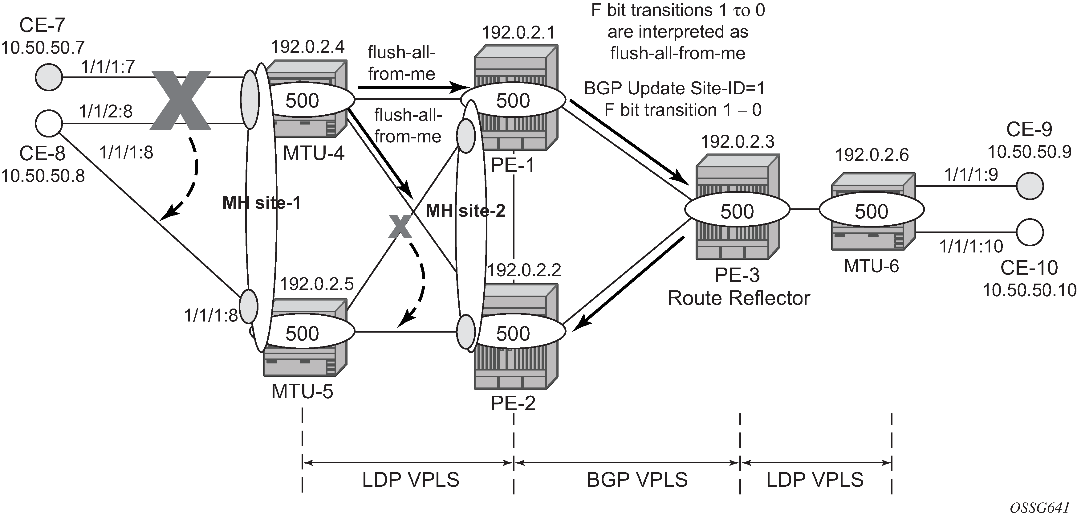
Node failures implicitly trigger a MAC flush on the remote nodes, because the TLDP/BGP session to the failed node goes down.
Access CE/PE signaling
BGP MH works at service level, therefore no physical ports are torn down on the non-DF, but rather the objects are brought down operationally, while the physical port will stay up and used for any other services existing on that port. Due to this reason, there is a need for signaling the standby status of an object to the remote PE or CE.
Access PEs running BGP MH on spoke SDPs and elected non-DF, will signal pseudowire standby status (0x20) to the other end. If no pseudowire status is supported on the remote MTU, a label withdrawal is performed. If there is more than one spoke SDP on the site (part of the same SHG), the signaling is sent for all the pseudowires of the site.
Note:The configure service vpls x spoke-sdp y:z no pw-status-signaling parameter allows to send a TLDP label-withdrawal instead of pseudowire status bits, even though the peer supports pseudowire status.
Multi-homed CEs connected through SAPs to the PEs running BGP MH, are signaled by the PEs using Y.1731 CFM, either by stopping the transmission of CCMs or by sending CCMs with isDown (interface status down encoding in the interface status TLV).
In this example, down MEPs on MTU-4 SAP 1/1/2:8 and CE-8 SAP 1/1/2:8 are configured. In a similar way, other MEPs can be configured on MTU-4 SAP 1/1/1:7, MTU-5 SAP 1/1/1:8, and CE-8 SAP 1/1/1:7 and SAP 1/1/1:8. Access PE/CE signaling shows the MEPs on MTU-4 SAP 1/1/2:8 and CE-8. Upon failure on the MTU-4 site MH-site-1, the MEP 48 will start sending CCMs with interface status down.
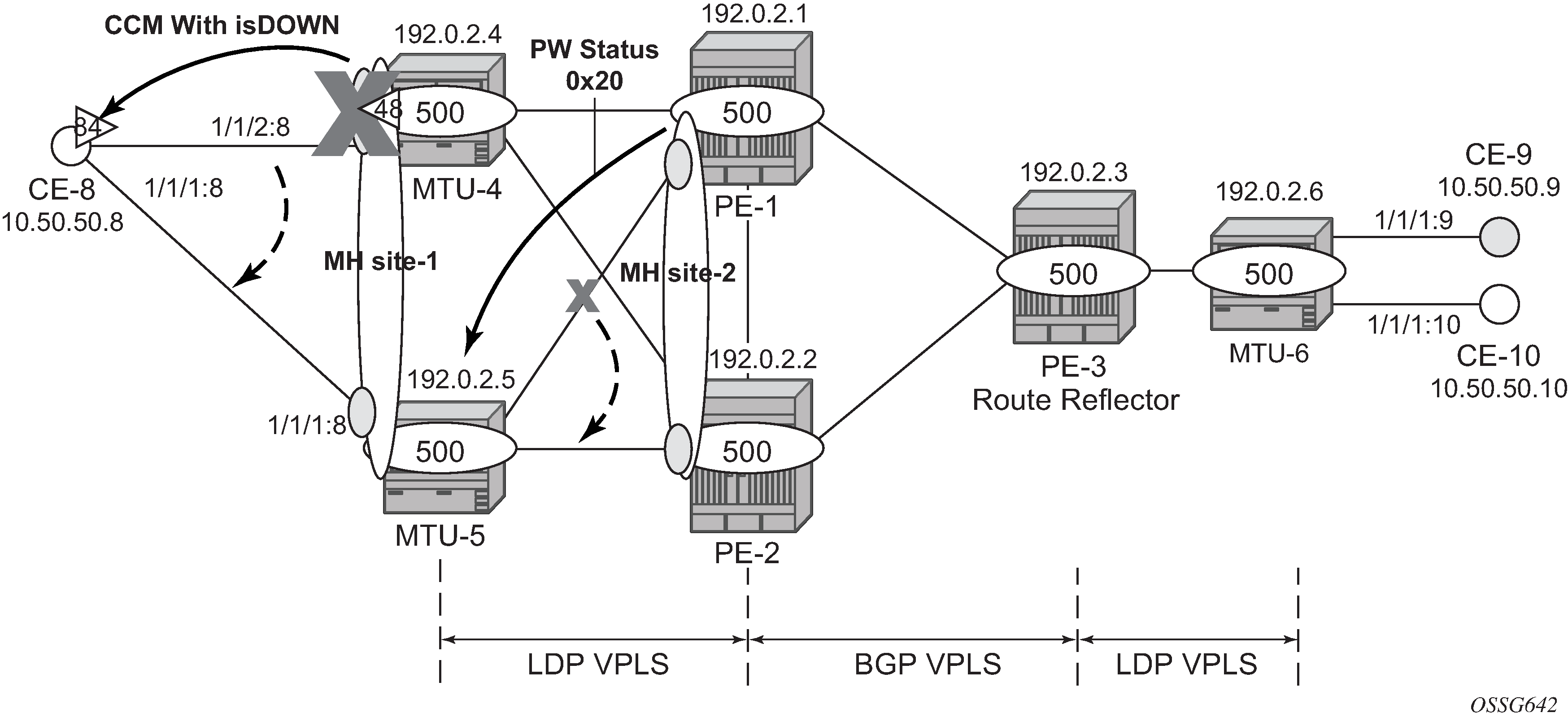
The CFM configuration required at SAP 1/1/2:8 is as follows. Down MEPs will be configured on CE-8 and MTU-5 SAPs in the same way, but in a different association. The option fault-propagation-enable use-if-tlv must be added. In case the CE does not understand the CCM interface status TLV, the fault-propagation-enable suspend-ccm option can be enabled instead. This will stop the transmission of CCMs upon site failures. Detailed configuration guidelines for Y.1731 are beyond the scope of this chapter.
# on MTU-4:
configure
    eth-cfm
        domain 1 format none level 3 admin-name "domain-1"
            association 1 format icc-based name "Association48" admin-name "assoc-1"
                bridge-identifier 500
                exit
                ccm-interval 1
                remote-mepid 84
            exit
        exit
# on MTU-4:
configure
    service
        vpls "VPLS 500"
            sap 1/1/2:8 split-horizon-group "site-1" create
                eth-cfm
                    mep 48 domain 1 association 1 direction down
                        fault-propagation-enable use-if-tlv
                        ccm-enable
                        no shutdown
                    exit
                exit
            exit
If CE-8 is a service router, upon receiving a CCM with isDown, an alarm will be triggered and the SAP will be brought down:
# on CE-8:
67 2021/01/19 09:13:19.447 UTC WARNING: OSPF #2047 vprn8 VR:  2 OSPFv2 (0)
"LCL_RTR_ID 10.50.50.8: Interface int-CE-8-MTU-4 state changed to down
(event IF_DOWN)"

66 2021/01/19 09:13:19.447 UTC WARNING: SNMP #2004 vprn8 int-CE-8-MTU-4
"Interface int-CE-8-MTU-4 is not operational"

65 2021/01/19 09:13:19.447 UTC MINOR: SVCMGR #2203 vprn8
"Status of SAP 1/1/2:8 in service 8 (customer 1) changed to admin=up oper=down
 flags=OamDownMEPFault "

64 2021/01/19 09:13:19.447 UTC MINOR: SVCMGR #2108 vprn8
"Status of interface int-CE-8-MTU-4 in service 8 (customer 1) changed to admin=up
 oper=down"

63 2021/01/19 09:13:19.447 UTC MINOR: ETH_CFM #2001 Base
"MEP 1/1/84 highest defect is now defRemoteCCM"
On CE-8, the status of the SAP can be verified as follows:
*A:CE-8# show service id 8 sap 1/1/2:8

===============================================================================
Service Access Points(SAP)
===============================================================================
Service Id         : 8
SAP                : 1/1/2:8                  Encap             : q-tag
Description        : (Not Specified)
Admin State        : Up                       Oper State        : Down
Flags              : OamDownMEPFault
Multi Svc Site     : None
Last Status Change : 01/19/2021 09:13:19
Last Mgmt Change   : 01/19/2021 09:00:42
===============================================================================
As also depicted in Access PE/CE signaling, PE-1 will signal pseudowire status standby (code 0x20) when PE-1 goes to non-DF state for MH-site-2. MTU-5 will receive that signaling and, based on the ignore-standby-signaling parameter, will decide whether to send the broadcast, unknown unicast, and multicast (BUM) traffic to PE-1. In case MTU-5 uses in its configuration ignore-standby-signaling, it will be sending BUM traffic on both pseudowires at the same time (which is not normally desired), ignoring the pseudowire status bits. The following output shows the MTU-5 spoke-SDP receiving the pseudowire status signaling. Although the spoke SDP stays operationally up, the Peer Pw Bits field shows pwFwdingStandby and MTU-5 will not send any traffic if the ignore-standby-signaling parameter is disabled.
*A:MTU-5# show service id 500 sdp 51:500 detail

===============================================================================
Service Destination Point (Sdp Id : 51:500) Details
===============================================================================
-------------------------------------------------------------------------------
 Sdp Id 51:500  -(192.0.2.1)
-------------------------------------------------------------------------------
Description     : (Not Specified)
SDP Id             : 51:500                   Type              : Spoke
Spoke Descr     : (Not Specified)
Split Horiz Grp    : (Not Specified)
Etree Root Leaf Tag: Disabled                 Etree Leaf AC     : Disabled
VC Type            : Ether                    VC Tag            : n/a
Admin Path MTU     : 8000                     Oper Path MTU     : 8000
Delivery           : MPLS
Far End            : 192.0.2.1                Tunnel Far End    : n/a
Oper Tunnel Far End: 192.0.2.1
LSP Types          : RSVP
---snip---

Admin State        : Up                       Oper State        : Up
---snip---

Endpoint           : N/A                      Precedence        : 4
PW Status Sig      : Enabled
Force Vlan-Vc      : Disabled                 Force Qinq-Vc     : none
Class Fwding State : Down
Flags              : None
Time to RetryReset : never                    Retries Left      : 3
Mac Move           : Blockable                Blockable Level   : Tertiary
Local Pw Bits      : None
Peer Pw Bits       : pwFwdingStandby
---snip---
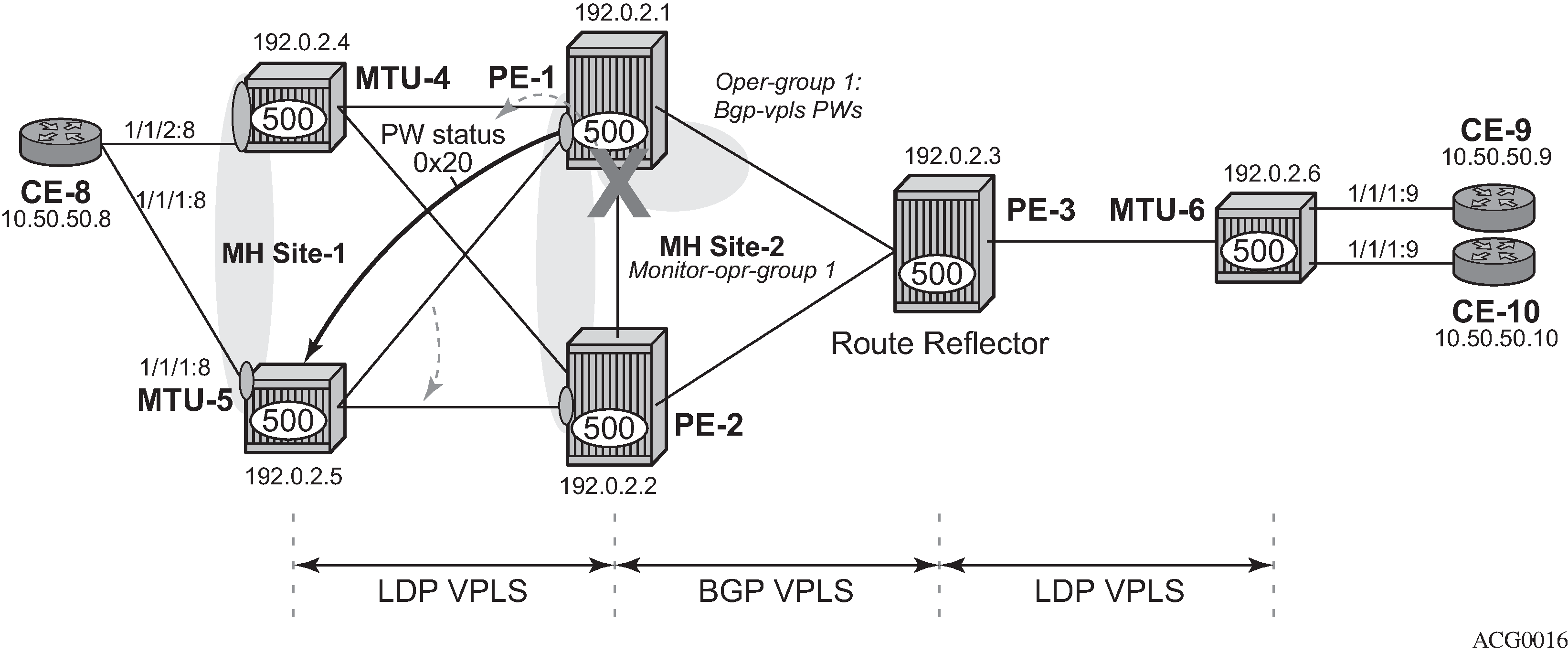
Operational groups for BGP-MH
Operational groups (oper-group) introduce the capability of grouping objects into a generic group object and associating its status to other service endpoints (pseudowires, SAPs, IP interfaces) located in the same or in different service instances. The operational group status is derived from the status of the individual components using certain rules specific to the application using the concept. A number of other service entities—the monitoring objects—can be configured to monitor the operational group status and to drive their own status based on the oper-group status. In other words, if the operational group goes down, the monitoring objects will be brought down. When one of the objects included in the operational group comes up, the entire group will also come up, and therefore so will the monitoring objects.
This concept can be used to enhance the BGP-MH solution for avoiding black-holes on the PE selected as the DF if the rest of the VPLS endpoints fail (pseudowire spoke(s)/pseudowire mesh and/or SAP(s)). Oper-groups and BGP-MH illustrates the use of operational groups together with BGP-MH. On PE-1 (and PE-2) all of the BGP-VPLS pseudowires in the core are configured under the same oper-group group-1. MH-site-2 is configured as a monitoring object. When the two BGP-VPLS pseudowires go down, oper-group group-1 will be brought down, therefore MH-site-2 on PE-1 will go down as well (PE-2 will become DF and PE-1 will signal standby to MTU-5).
In the preceding example, this feature provides a solution to avoid a black-hole when PE-1 loses its connectivity to the core.
Operational groups are configured in two steps:
Identify a set of objects whose forwarding state should be considered as a whole group, then group them under an operational group (in this case oper-group group-1, which is configured in the bgp pw-template-binding context).
Associate other existing objects (clients) with the oper-group using the monitor-group command (configured, in this case, in the site MH-site-2).
The following CLI excerpt shows the commands required (oper-group, monitor-oper-group).
# on PE-1:
configure
    service
        oper-group "group-1" create
        exit
        vpls 500
            bgp
                pw-template-binding 500 split-horizon-group "CORE"
                    oper-group "group-1"
                exit
            exit
            site "MH-site-2"
                monitor-oper-group "group-1"
            exit
When all the BGP-VPLS pseudowires go down, oper-group group-1 will go down and therefore the monitoring object, site MH-site-2, will also go down and PE-2 will then be elected as DF. The log 99 gives information about this sequence of events:
# on PE-1:
configure
    service
        sdp 12
            shutdown
        exit
        sdp 13
            shutdown
        exit
*A:PE-1# show log log-id 99
---snip---

147 2021/01/19 09:20:08.753 UTC WARNING: SVCMGR #2531 Base BGP-MH
"Service-id 500 site MH-site-2 is not the designated-forwarder"

146 2021/01/19 09:20:08.753 UTC MAJOR: SVCMGR #2316 Base
"Processing of a SDP state change event is finished and the status of all affected SDP Bindings on SDP 13 has been updated."

145 2021/01/19 09:20:08.752 UTC MINOR: SVCMGR #2306 Base
"Status of SDP Bind 15:500 in service 500 (customer 1) changed to admin=up oper=down flags="

144 2021/01/19 09:20:08.752 UTC MINOR: SVCMGR #2326 Base
"Status of SDP Bind 15:500 in service 500 (customer 1) local PW status bits changed to pwFwdingStandby "

143 2021/01/19 09:20:08.752 UTC MINOR: SVCMGR #2542 Base
"Oper-group group-1 changed status to down"
PE-1 is no longer the DF, as follows:
*A:PE-1# show service id 500 site

===============================================================================
VPLS Sites
===============================================================================
Site                Site-Id   Dest                Mesh-SDP  Admin   Oper  Fwdr
-------------------------------------------------------------------------------
MH-site-2           2         sdp:15:500          no        Enabled down  No
-------------------------------------------------------------------------------
Number of Sites : 1
-------------------------------------------------------------------------------
===============================================================================
PE-2 becomes the DF:
*A:PE-2# show service id 500 site

===============================================================================
VPLS Sites
===============================================================================
Site                Site-Id   Dest                Mesh-SDP  Admin   Oper  Fwdr
-------------------------------------------------------------------------------
MH-site-2           2         sdp:25:500          no        Enabled up    Yes
-------------------------------------------------------------------------------
Number of Sites : 1
-------------------------------------------------------------------------------
===============================================================================
The process reverts when at least one BGP-VPLS pseudowire comes back up.
Show commands and debugging options
The main command to find out the status of a site is the show service id x site command.
*A:MTU-5# show service id 500 site

===============================================================================
VPLS Sites
===============================================================================
Site                Site-Id   Dest                Mesh-SDP  Admin   Oper  Fwdr
-------------------------------------------------------------------------------
MH-site-1           1         sap:1/1/1:8         no        Enabled up    No
-------------------------------------------------------------------------------
Number of Sites : 1
-------------------------------------------------------------------------------
===============================================================================
A detail modifier is available:
*A:MTU-5# show service id 500 site detail

===============================================================================
Site Information
===============================================================================
Site Name            : MH-site-1
-------------------------------------------------------------------------------
Site Id              : 1
Dest                 : sap:1/1/1:8          Mesh-SDP Bind    : no
Admin Status         : Enabled              Oper Status      : up
Designated Fwdr      : No
DF UpTime            : 0d 00:00:00          DF Chg Cnt       : 1
Boot Timer           : default              Timer Remaining  : 0d 00:00:00
Site Activation Timer: default              Timer Remaining  : 0d 00:00:00
Min Down Timer       : default              Timer Remaining  : 0d 00:00:00
Failed Threshold     : default(all)
Monitor Oper Grp     : (none)
-------------------------------------------------------------------------------
Number of Sites : 1
===============================================================================
The detail view of the command displays information about the BGP MH timers. The values are only shown if the global values are overridden by specific ones at service level (and will be tagged with Ovr if they have been configured at service level). The Timer Remaining field reflects the count down from the boot/site activation timers down to the moment when this router tries to become DF again. Again, this is only shown when the global timers have been overridden by the ones at service level.
The objects on the non-DF site will be brought down operationally and flagged with StandByForMHProtocol, for example, for SAP 1/1/1:8 on non-DF MTU-5:
*A:MTU-5# show service id 500 sap 1/1/1:8

===============================================================================
Service Access Points(SAP)
===============================================================================
Service Id         : 500
SAP                : 1/1/1:8                  Encap             : q-tag
Description        : (Not Specified)
Admin State        : Up                       Oper State        : Down
Flags              : StandByForMHProtocol
Multi Svc Site     : None
Last Status Change : 01/19/2021 08:30:37
Last Mgmt Change   : 01/19/2021 08:47:52
===============================================================================
For spoke SDP 25:500 on non-DF PE-2:
*A:PE-2# show service id 500 sdp 25:500 detail

===============================================================================
Service Destination Point (Sdp Id : 25:500) Details
===============================================================================
-------------------------------------------------------------------------------
 Sdp Id 25:500  -(192.0.2.5)
-------------------------------------------------------------------------------
Description     : (Not Specified)
SDP Id             : 25:500                   Type              : Spoke
---snip---

Admin State        : Up                       Oper State        : Down
---snip---

Flags              : StandbyForMHProtocol
---snip---
The BGP MH routes in the RIB, RIB-In and RIB-Out can be shown by using the corresponding show router bgp routes and show router bgp neighbor x.x.x.x received-routes|advertised-routes commands. The BGP MH routes are only shown when the operator uses the l2-vpn family modifier. Should the operator want to filter only the BGP MH routes out of the l2-vpn routes, the multi-homing filter has to be added to the show router bgp routes commands.
*A:PE-3# show router bgp routes l2-vpn
===============================================================================
 BGP Router ID:192.0.2.3        AS:65000       Local AS:65000
===============================================================================
 Legend -
 Status codes  : u - used, s - suppressed, h - history, d - decayed, * - valid
                 l - leaked, x - stale, > - best, b - backup, p - purge
 Origin codes  : i - IGP, e - EGP, ? - incomplete

===============================================================================
BGP L2VPN Routes
===============================================================================
Flag  RouteType                   Prefix                             MED
      RD                          SiteId                             Label
      Nexthop                     VeId                   BlockSize   LocalPref
      As-Path                     BaseOffset             vplsLabelBa
                                                         se
-------------------------------------------------------------------------------
u*>i  VPLS                        -                      -           0
      65000:501                   -                                  -
      192.0.2.1                   501                    8           100
      No As-Path                  497                    524271
u*>i  MultiHome                   -                      -           0
      65000:501                   2                                  -
      192.0.2.1                   -                      -           100
      No As-Path                  -                      -
u*>i  VPLS                        -                      -           0
      65000:502                   -                                  -
      192.0.2.2                   502                    8           100
      No As-Path                  497                    524271
u*>i  MultiHome                   -                      -           0
      65000:502                   2                                  -
      192.0.2.2                   -                      -           100
      No As-Path                  -                      -
-------------------------------------------------------------------------------
Routes : 4
===============================================================================
For the L2 VPN BGP routes toward site 2 (PE-1 and PE-2) in detail:
*A:PE-3# show router bgp routes l2-vpn multi-homing siteid 2 detail
===============================================================================
 BGP Router ID:192.0.2.3        AS:65000       Local AS:65000
===============================================================================
 Legend -
 Status codes  : u - used, s - suppressed, h - history, d - decayed, * - valid
                 l - leaked, x - stale, > - best, b - backup, p - purge
 Origin codes  : i - IGP, e - EGP, ? - incomplete

===============================================================================
BGP L2VPN-MULTIHOME Routes
===============================================================================
Original Attributes

Route Type     : MultiHome
Route Dist.    : 65000:501
Site Id        : 2
Nexthop        : 192.0.2.1
From           : 192.0.2.1
Res. Nexthop   : n/a
Local Pref.    : 100                    Interface Name : NotAvailable
Aggregator AS  : None                   Aggregator     : None
Atomic Aggr.   : Not Atomic             MED            : 0
AIGP Metric    : None                   IGP Cost       : n/a
Connector      : None
Community      : target:65000:500
                 l2-vpn/vrf-imp:Encap=19: Flags=-DF: MTU=0: PREF=0
Cluster        : No Cluster Members
Originator Id  : None                   Peer Router Id : 192.0.2.1
Flags          : Used Valid Best IGP
Route Source   : Internal
AS-Path        : No As-Path
Route Tag      : 0
Neighbor-AS    : n/a
Orig Validation: N/A
Source Class   : 0                      Dest Class     : 0
Add Paths Send : Default
Last Modified  : 00h05m40s

Modified Attributes
 ---snip---

-------------------------------------------------------------------------------Original Attributes

Route Type     : MultiHome
Route Dist.    : 65000:502
Site Id        : 2
Nexthop        : 192.0.2.2
From           : 192.0.2.2
Res. Nexthop   : n/a
Local Pref.    : 100                    Interface Name : NotAvailable
Aggregator AS  : None                   Aggregator     : None
Atomic Aggr.   : Not Atomic             MED            : 0
AIGP Metric    : None                   IGP Cost       : n/a
Connector      : None
Community      : target:65000:500
                 l2-vpn/vrf-imp:Encap=19: Flags=none: MTU=0: PREF=0
Cluster        : No Cluster Members
Originator Id  : None                   Peer Router Id : 192.0.2.2
Flags          : Used Valid Best IGP
Route Source   : Internal
AS-Path        : No As-Path
Route Tag      : 0
Neighbor-AS    : n/a
Orig Validation: N/A
Source Class   : 0                      Dest Class     : 0
Add Paths Send : Default
Last Modified  : 00h05m40s

Modified Attributes
 ---snip---

-------------------------------------------------------------------------------
-------------------------------------------------------------------------------
Routes : 2
===============================================================================
The following shows the Layer 2 BGP routes on PE-1:
*A:PE-1# show service l2-route-table ?
  - l2-route-table [detail] [bgp-ad] [multi-homing] [bgp-vpls] [bgp-vpws] [all-routes]

 <detail>             : keyword - display detailed information
*A:PE-1# show service l2-route-table multi-homing

===============================================================================
Services: L2 Multi-Homing Route Information - Summary
===============================================================================
Svc Id     L2-Routes (RD-Prefix)        Next Hop        SiteId     State  DF
-------------------------------------------------------------------------------
500        65000:502                    192.0.2.2       2          up(0)  clear
-------------------------------------------------------------------------------
No. of L2 Multi-Homing Route Entries: 1
===============================================================================
In case PE-3 were the RR for MTU-4 and MTU-5 as well as for PE-1 and PE-2, PE-1 would have two more L2-routes for multi-homing in this table, as follows:
*A:PE-1# show service l2-route-table multi-homing

===============================================================================
Services: L2 Multi-Homing Route Information - Summary
===============================================================================
Svc Id     L2-Routes (RD-Prefix)        Next Hop        SiteId     State  DF
-------------------------------------------------------------------------------
500        65000:504                    192.0.2.4       1          up(0)  set
500        65000:505                    192.0.2.5       1          up(0)  clear
500        65000:502                    192.0.2.2       2          up(0)  clear
-------------------------------------------------------------------------------
No. of L2 Multi-Homing Route Entries: 3
===============================================================================
When operational groups are configured (as previously shown), the following show command helps to find the operational dependencies between monitoring objects and group objects.
*A:PE-1# show service oper-group "group-1" detail

===============================================================================
Service Oper Group Information
===============================================================================
Oper Group       : group-1
Creation Origin  : manual                          Oper Status: up
Hold DownTime    : 0 secs                          Hold UpTime: 4 secs
Members          : 2                               Monitoring : 1
===============================================================================

===================================================================
Member SDP-Binds for OperGroup: group-1
===================================================================
SdpId            SvcId      Type     IP address      Adm     Opr
-------------------------------------------------------------------
12:4294967292    500        BgpVpls  192.0.2.2       Up      Up
13:4294967293    500        BgpVpls  192.0.2.3       Up      Up
-------------------------------------------------------------------
SDP Entries found: 2
===================================================================

===============================================================================
Monitoring Sites for OperGroup: group-1
===============================================================================
SvcId     Site                Site-Id   Dest                Admin   Oper  Fwdr
-------------------------------------------------------------------------------
500       MH-site-2           2         sdp:15:500          Enabled up    Yes
-------------------------------------------------------------------------------
Site Entries found: 1
===============================================================================
For debugging, the following CLI sources can be used:
log-id 99 — Provides information about the site object changes and DF changes.
debug router bgp update command — Shows the BGP updates for BGP MH, including the sent and received BGP MH NLRIs and flags.
# on MTU-4:
debug
    router
        bgp
            update
debug router ldp command — Provides information about the pseudowire status bits being signaled as well as the MAC flush messages.
# on MTU-4:
debug
    router
        ldp
            peer 192.0.2.1
                packet
                    init detail
                    label detail
As an example, log-id 99 shows the following debug output after disabling MH-site-1 on MTU-4:
# on MTU-4:
configure
    service
        vpls "VPLS 500"
            sap 1/1/1:7
                shutdown
            exit
            sap 1/1/2:8
                shutdown
            exit
*A:MTU-4# show log log-id 99
===============================================================================
Event Log 99
===============================================================================
---snip---

122 2021/01/19 09:38:17.885 UTC WARNING: SVCMGR #2531 Base BGP-MH
"Service-id 500 site MH-site-1 is not the designated-forwarder"

121 2021/01/19 09:38:17.884 UTC MINOR: SVCMGR #2203 Base
"Status of SAP 1/1/2:8 in service 500 (customer 1) changed to admin=down oper=down flags=SapAdminDown MhStandby"

---snip---
Log 2 has been configured to log BGP updates and LDP commands.
*A:MTU-4# show log log-id 2
===============================================================================
Event Log 2
===============================================================================
---snip---

4 2021/01/19 09:38:17.893 UTC MINOR: DEBUG #2001 Base Peer 1: 192.0.2.3
"Peer 1: 192.0.2.3: UPDATE
Peer 1: 192.0.2.3 - Received BGP UPDATE:
    Withdrawn Length = 0
    Total Path Attr Length = 86
    Flag: 0x90 Type: 14 Len: 28 Multiprotocol Reachable NLRI:
        Address Family L2VPN
        NextHop len 4 NextHop 192.0.2.5
        [MH] site-id: 1, RD 65000:505
    Flag: 0x40 Type: 1 Len: 1 Origin: 0
    Flag: 0x40 Type: 2 Len: 0 AS Path:
    Flag: 0x80 Type: 4 Len: 4 MED: 0
    Flag: 0x40 Type: 5 Len: 4 Local Preference: 100
    Flag: 0x80 Type: 9 Len: 4 Originator ID: 192.0.2.5
    Flag: 0x80 Type: 10 Len: 4 Cluster ID:
        1.1.1.1
    Flag: 0xc0 Type: 16 Len: 16 Extended Community:
        target:65000:500
        l2-vpn/vrf-imp:Encap=19: Flags=-DF: MTU=0: PREF=0
"

2 2021/01/19 09:38:17.885 UTC MINOR: DEBUG #2001 Base Peer 1: 192.0.2.3
"Peer 1: 192.0.2.3: UPDATE
Peer 1: 192.0.2.3 - Send BGP UPDATE:
    Withdrawn Length = 0
    Total Path Attr Length = 72
    Flag: 0x90 Type: 14 Len: 28 Multiprotocol Reachable NLRI:
        Address Family L2VPN
        NextHop len 4 NextHop 192.0.2.4
        [MH] site-id: 1, RD 65000:504
    Flag: 0x40 Type: 1 Len: 1 Origin: 0
    Flag: 0x40 Type: 2 Len: 0 AS Path:
    Flag: 0x80 Type: 4 Len: 4 MED: 0
    Flag: 0x40 Type: 5 Len: 4 Local Preference: 100
    Flag: 0xc0 Type: 16 Len: 16 Extended Community:
        target:65000:500
        l2-vpn/vrf-imp:Encap=19: Flags=D: MTU=0: PREF=0
"

1 2021/01/19 09:38:17.885 UTC MINOR: DEBUG #2001 Base LDP
"LDP: LDP
Send Address Withdraw packet (msgId 348) to 192.0.2.1:0
Protocol version = 1
MAC Flush (All MACs learned from me)
Service FEC PWE3: ENET(5)/500 Group ID = 0 cBit = 0
"
Assuming all the recommended tools are enabled, a DF to non-DF transition can be shown as well as the corresponding MAC flush messages and related BGP processing.
If MH-site-2 is torn down on PE-1, the debug router bgp update command would allow us to see two BGP updates from PE-1:
A BGP MH update for site-id 2 with flag D set (because the site is down).
A BGP VPLS update for veid=501 and flag D set. This is due to the fact that there are no more active objects on the VPLS, besides the BGP pseudowires.
# on PE-1:
configure
    service
        vpls "VPLS 500"
            spoke-sdp 14:500
                shutdown
            exit
            spoke-sdp 15:500
                shutdown
            exit
*A:PE-1# show log log-id 2 =============================================================================== Event Log 2 =============================================================================== ---snip--- 5 2021/01/19 09:42:39.897 UTC MINOR: DEBUG #2001 Base Peer 1: 192.0.2.3 "Peer 1: 192.0.2.3: UPDATE Peer 1: 192.0.2.3 - Send BGP UPDATE: Withdrawn Length = 0 Total Path Attr Length = 72 Flag: 0x90 Type: 14 Len: 28 Multiprotocol Reachable NLRI: Address Family L2VPN NextHop len 4 NextHop 192.0.2.1 [VPLS/VPWS] preflen 17, veid: 501, vbo: 497, vbs: 8, label-base: 524271, RD 65000:501 Flag: 0x40 Type: 1 Len: 1 Origin: 0 Flag: 0x40 Type: 2 Len: 0 AS Path: Flag: 0x80 Type: 4 Len: 4 MED: 0 Flag: 0x40 Type: 5 Len: 4 Local Preference: 100 Flag: 0xc0 Type: 16 Len: 16 Extended Community: target:65000:500 l2-vpn/vrf-imp:Encap=19: Flags=D: MTU=1514: PREF=0 " 4 2021/01/19 09:42:39.897 UTC MINOR: DEBUG #2001 Base Peer 1: 192.0.2.3 "Peer 1: 192.0.2.3: UPDATE Peer 1: 192.0.2.3 - Send BGP UPDATE: Withdrawn Length = 0 Total Path Attr Length = 72 Flag: 0x90 Type: 14 Len: 28 Multiprotocol Reachable NLRI: Address Family L2VPN NextHop len 4 NextHop 192.0.2.1 [MH] site-id: 2, RD 65000:501 Flag: 0x40 Type: 1 Len: 1 Origin: 0 Flag: 0x40 Type: 2 Len: 0 AS Path: Flag: 0x80 Type: 4 Len: 4 MED: 0 Flag: 0x40 Type: 5 Len: 4 Local Preference: 100 Flag: 0xc0 Type: 16 Len: 16 Extended Community: target:65000:500 l2-vpn/vrf-imp:Encap=19: Flags=D: MTU=0: PREF=0 "
The D flag, sent along with the BGP VPLS update for veid 501, would be seen on the remote core PEs as though it was a pseudowire status fault (although there is no TLDP running in the core).
*A:PE-2# show service id 500 all | match Flag
Flags              : PWPeerFaultStatusBits
Flags              : None
Flags              : None
Flags              : None
Conclusion
SR OS supports a wide range of service resiliency options as well as the best-of-breed system level HA and MPLS mechanisms for the access and the core. BGP MH for VPLS completes the service resiliency tool set by adding a mechanism that has some good advantages over the alternative solutions:
BGP MH provides a common resiliency mechanism for attachment circuits (SAPs), pseudowires (spoke SDPs), split horizon groups and mesh bindings
BGP MH is a network-based technique which does not need interaction to the CE or MTU to which it is providing redundancy to.
The examples used in this chapter illustrate the configuration of BGP MH for access CEs and MTUs. Show and debug commands have also been suggested so that the operator can verify and troubleshoot the BGP MH procedures.