Data Center Interconnect Using Dual EVPN-VXLAN Instance VPLS
This chapter provides information about Data Center Interconnect using dual EVPN-VXLAN instance VPLS.
Topics in this chapter include:
Applicability
This chapter was initially written for SR OS Release 16.0.R7, but the CLI in the current edition is based on SR OS Release 21.7.R1. Dual EVPN-VXLAN instances are supported in SR OS Release 16.0.R2, or later.
This chapter describes the redundancy based on an Anycast solution, as supported in SR OS Release 16.0, and later. For I-ES based redundancy scenarios as supported in SR OS Release 19.10, and later, see the EVPN Interconnect Ethernet Segments in Dual EVPN-VXLAN Instance VPLS Services chapter.
Overview
Chapter EVPN-MPLS Interconnect for EVPN-VXLAN VPLS Services describes a Data Center Interconnect (DCI) scenario using VXLAN in the DCs and MPLS in the WAN. This chapter describes a similar scenario, where the core is an IP network that does not use MPLS, and where end-to-end VXLAN is used instead. The DC Gateways (GWs) contain VPLS services with two EVPN-VXLAN instances and two BGP instances: one EVPN-VXLAN instance faces the DC and the other EVPN-VXLAN instance faces the WAN.
Dual EVPN-VXLAN instance VPLS 1 shows the example topology with two DCs. On PE-1 and PE-6, VPLS 1 is configured with one VXLAN instance and one BGP instance. On the DC GWs, VPLS 1 is configured with two VXLAN instances and two BGP instances: one toward the DC and one toward the WAN.
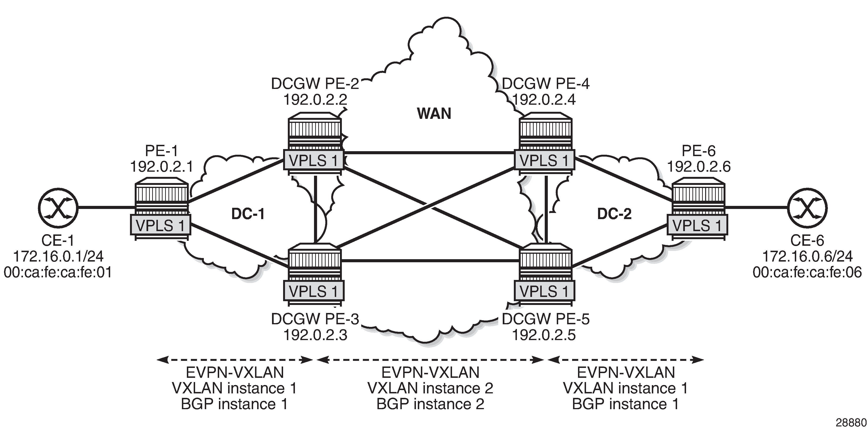
For example, on DC GW PE-2, VPLS 1 is configured with VXLAN instance 1 using BGP instance 1 and VXLAN 2 using BGP instance 2. In this example, the BGP instance ID matches the VXLAN instance ID, but that is not required. Each VXLAN instance has a different VNI and a different BGP instance.
# on PE-2:
configure
    service
        system
            bgp-auto-rd-range 10.0.0.1 comm-val 60000 to 65000
        exit
        vpls 1 name "VPLS 1" customer 1 create
            description "dual evpn-vxlan VPLS"
            vxlan instance 1 vni 11 create
            exit
            vxlan instance 2 vni 12 create
            exit
            bgp
                route-distinguisher auto-rd
                route-target export target:64500:11 import target:64500:11
            exit
            bgp 2
                route-distinguisher auto-rd
                route-target export target:64500:12 import target:64500:12
            exit
            bgp-evpn
                evi 1
                vxlan bgp 1 vxlan-instance 1
                    no shutdown
                exit
                vxlan bgp 2 vxlan-instance 2
                    no shutdown
                exit
            exit
            no shutdown
When different BGP instances are configured, the auto-derived route distinguishers (RDs) in BGP instance 1 and BGP instance 2 are different, as follows:
*A:PE-2# show service id 1 bgp 1 | match "Route Dist"
Route Dist           : auto-rd
Oper Route Dist      : 10.0.0.1:60000
*A:PE-2# show service id 1 bgp 2 | match "Route Dist"
Route Dist           : auto-rd
Oper Route Dist      : 10.0.0.1:60001
Dual EVPN-VXLAN instance VPLSs can contain SAPs in SR OS Release 19.10.R1, and later. However, dual EVPN-VXLAN instance VPLSs cannot contain any SDP bindings in SR OS Release 21.7.R1, as follows:
*A:PE-2>config>service>vpls# spoke-sdp 21:1 create
MINOR: SVCMGR #1997 Cannot create sdp binding - not supported with multiple vxlan instances
This chapter describes the redundancy based on an Anycast solution, as supported in SR OS Release 16.0, and later. For I-ES based redundancy scenarios as supported in SR OS Release 19.10, and later, see chapter EVPN Multi-Homing on Dual EVPN-VXLAN BGP Instance VPLS.
To provide DC GW redundancy, an anycast IP address can be configured for the dual EVPN-VXLAN instance VPLSs on the DC GWs.
EVPN route types 2 and 3 are processed by dual EVPN-VXLAN VPLS services as follows:
Route type 2: MAC/IP routes
MAC/IP routes received in a BGP instance will be imported and—according to the selection rules—installed in the FDB.
Active MAC routes are re-advertised in the other BGP instance with new BGP attributes (RD, route target (RT), and so on).
Only the best EVPN MAC route is redistributed.
The MAC/IP information and the sticky bit are propagated. The only exception is the Ethernet Segment Identifier (ESI). A non-zero ESI will be reset unless the auto-disc-route-advertisement command is configured.
When an attribute has changed for a redistributed MAC route, the MAC route will be updated if it is still the best route. For example, an update of the sequence number or the sticky bit can trigger a redistribution.
Route type 3: inclusive multicast routes
EVPN inclusive multicast routes are generated independently for each instance with the proper BGP extended communities.
Ingress Replication (IR) or Assisted Replication (AR) Inclusive Multicast Ethernet Tag (IMET) routes are supported.
The inclusive multicast originating IP can be configured with an anycast address:
The configured originating IP address is encoded in the originating IP field of the IMET-IR routes; the originating IP field of the IMET-AR routes is still derived from the assisted replication IP value in the service system settings for VXLAN.
If a router receives two IMET routes with the same originating IP address, different RDs, and different next-hops, it sets up two bindings: one to each next-hop.
If a router receives two IMET routes with the same originating IP address, the same RD, but different next-hops, it sets up one binding to the next-hop with the lowest IP address.
If a router receives two IMET routes with the same originating IP address, different RDs, but the same next-hop, it sets up one binding to the next-hop.
A DC GW will not set up a binding to its DC GW peer if the received originating IP equals its own originating IP, regardless of whether the local RD and the remote RD are the same or different.
Configuration
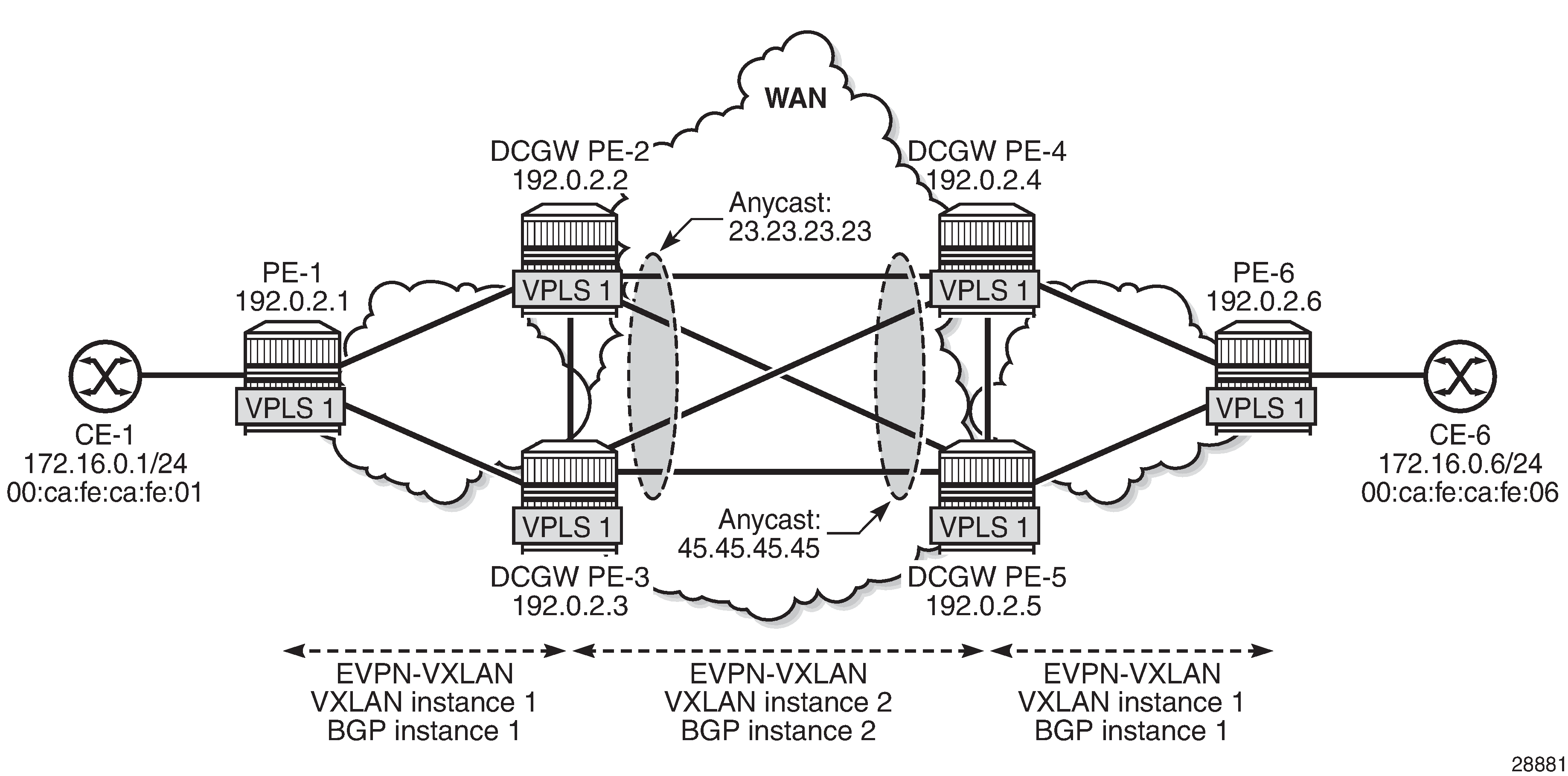
Example topology with VPLS 1 and anycast addresses shows the example topology. Redundancy is based on anycast: on the DC GWs PE-2 and PE-3, anycast address 23.23.23.23 is configured as inclusive multicast originating IP; on PE-4 and PE-5 in DC-2, the anycast address is 45.45.45.45. However, no Ethernet segments are used in this example.
The initial configuration includes:
Cards, MDAs, ports
Router interfaces
IS-IS as IGP (level 1 in the DCs and level 2 in the WAN)
MPLS is not configured in any of these networks.
BGP configuration
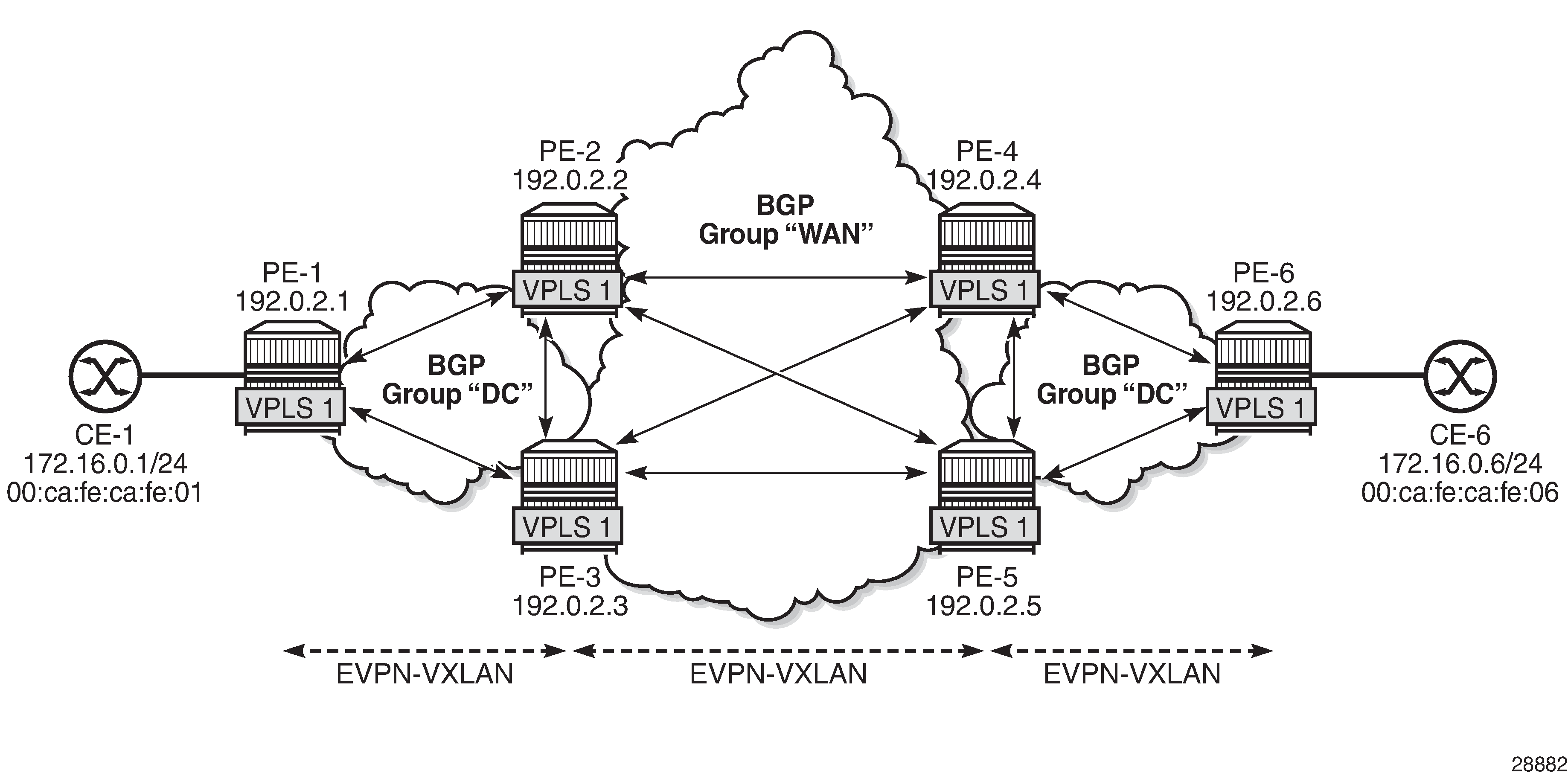
BGP is configured for the EVPN address family on all nodes. Example topology with BGP groups shows the BGP groups: on the DC GWs, both BGP group "DC" and "WAN" are defined. Route policies ensure that only DC routes are forwarded to DC neighbors and only WAN routes are forwarded to WAN neighbors. Also, DC GWs need to drop BGP-EVPN routes from the local peer DC GW.
The BGP configuration on PE-1 is as follows. The configuration on PE-6 is similar.
# on PE-1:
configure
    router Base
        autonomous-system 64500
        bgp
            family evpn
            vpn-apply-import
            vpn-apply-export
            rapid-withdrawal
            rapid-update evpn
            group "DC"
                type internal
                neighbor 192.0.2.2
                exit
                neighbor 192.0.2.3
                exit
            exit
On the DC GWs, two BGP groups are defined: one for the DC group and one for the WAN group. Export policies ensure that only DC routes are exported to the DC group and only WAN routes are exported to the WAN group. Import policies ensure that routes from the local DC GW are dropped; for example, PE-2 drops routes from PE-3, and vice versa. The policies will be described later. The BGP configuration on PE-2 is as follows. The BGP configuration on the other DC GWs is similar.
# on PE-2:
configure
    router Base
        autonomous-system 64500
        bgp
            family evpn
            vpn-apply-import
            vpn-apply-export
            rapid-withdrawal
            rapid-update evpn
            group "DC"
                type internal
                import "drop SOO-DCGW-23"
                export "allow only DC and add SOO"
                neighbor 192.0.2.1
                exit
                neighbor 192.0.2.3
                exit
            exit
            group "WAN"
                type internal
                import "drop SOO-DCGW-23"
                export "allow only WAN and add SOO"
                neighbor 192.0.2.4
                exit
                neighbor 192.0.2.5
                exit
            exit
        exit
Route policies
The route policies are equivalent to the policies described in the chapter EVPN-MPLS Interconnect for EVPN-VXLAN VPLS Services. In this example, no filtering can be done based on the encapsulation extended community (VXLAN versus MPLS), because only VXLAN is used in the DCs and the WAN. Therefore, the route tag is used as a criterion instead in the route policies "allow only DC and add SOO" (Site of Origin) and "allow only WAN and add SOO". When two BGP instances for the same encapsulation are configured in a VPLS, different route tags in each BGP instance are required. In this example, route tag 11 is used in BGP instance 1 in the DCs and route tag 12 is used in BGP instance 2 in the WAN.
When redistributing to the other BGP instance, route filtering toward DC or WAN will be based on the route tags. Export policy "allow only DC and add SOO" drops routes with WAN route tag 12. Likewise, export policy "allow only WAN and add SOO" drops routes with DC route tag 11. Filtering matching on route tags on EVPN BGP instances is scalable, because only two route tags are required per PE. Filtering matching on route target (RT) is also possible, but in that case, two RTs per service are required. This does not scale well and is cumbersome.
The export policy "allow only DC and add SOO" ensures that EVPN routes with route tag 12 are dropped and only DC routes are forwarded. This route policy is applied in the BGP group "DC" context. Likewise, the export policy "allow only WAN and add SOO" drops EVPN routes with route tag 11, so that only WAN EVPN routes are forwarded.
Both policies also add a site of origin, such as "SOO-23" for PE-2 and PE-3, and "SOO-45" for PE-4 and PE-5. This SOO is used for filtering in the import policies "drop SOO-DCGW-23" and "drop SOO-DCGW-45" to ensure that, for instance, PE-2 drops routes advertised by the local peer PE-3 with the same SOO-23, and vice versa. Likewise, PE-4 drops routes advertised by its local peer PE-5 with the same SOO-45, and vice versa.
The following policies are configured on DC GWs PE-2 and PE-3:
# on PE-2, PE-3:
configure
    router Base
        policy-options
            begin
            community "SOO-23"
                members "origin:64500:23"
            exit
            policy-statement "drop SOO-DCGW-23"
                entry 10
                    from
                        community "SOO-23"
                        family evpn
                    exit
                    action drop
                    exit
                exit
            exit
            policy-statement "allow only DC and add SOO"
                entry 10
                    from
                        tag 12
                        family evpn
                    exit
                    action drop
                    exit
                exit
                entry 20
                    from
                        family evpn
                    exit
                    action accept
                        community add "SOO-23"
                    exit
                exit
            exit
            policy-statement "allow only WAN and add SOO"
                entry 10
                    from
                        tag 11
                        family evpn
                    exit
                    action drop
                    exit
                exit
                entry 20
                    from
                        family evpn
                    exit
                    action accept
                        community add "SOO-23"
                    exit
                exit
            exit
            commit
The following policies are configured on DC GWs PE-4 and PE-5:
# on PE-4, PE-5:
configure
    router Base
        policy-options
            begin
            community "SOO-45"
                members "origin:64500:45"
            exit
            policy-statement "drop SOO-DCGW-45"
                entry 10
                    from
                        community "SOO-45"
                        family evpn
                    exit
                    action drop
                    exit
                exit
            exit
            policy-statement "allow only DC and add SOO"
                entry 10
                    from
                        tag 12
                        family evpn
                    exit
                    action drop
                    exit
                exit
                entry 20
                    from
                        family evpn
                    exit
                    action accept
                        community add "SOO-45"
                    exit
                exit
            exit
            policy-statement "allow only WAN and add SOO"
                entry 10
                    from
                        tag 11
                        family evpn
                    exit
                    action drop
                    exit
                exit
                entry 20
                    from
                        family evpn
                    exit
                    action accept
                        community add "SOO-45"
                    exit
                exit
            exit
            commit
VPLS configuration
On PE-2 and PE-3, the service configuration is identical and VPLS 1 is configured as follows. For redundancy, the anycast IP address 23.23.23.23 is configured as inclusive multicast originating IP on PE-2 and PE-3. The RT is the same in all nodes: the RT is 64500:11 in BGP instance 1 of VPLS 1; in BGP instance 2, the RT is 64500:12. The RD is 64500:2311 in BGP instance 1 of VPLS 1 and 64500:2312 in BGP instance 2 of VPLS 1 on PE-2 and PE-3. The RD must be the same in PE-2 and PE-3 because they are part of the anycast group, but the RD in PE-1 must be different.
# on PE-2, PE-3:
configure
    service
        vpls 1 name "VPLS 1" customer 1 create
            vxlan instance 1 vni 11 create
            exit
            vxlan instance 2 vni 12 create
            exit
            bgp
                route-distinguisher 64500:2311
                route-target export target:64500:11 import target:64500:11
            exit
            bgp 2
                route-distinguisher 64500:2312
                route-target export target:64500:12 import target:64500:12
            exit
            bgp-evpn
                incl-mcast-orig-ip 23.23.23.23
                evi 1
                vxlan bgp 1 vxlan-instance 1
                    default-route-tag 11
                    no shutdown
                exit
                vxlan bgp 2 vxlan-instance 2
                    default-route-tag 12
                    no shutdown
                exit
            exit
            no shutdown
On PE-1, VPLS 1 is configured with VXLAN instance 1 and BGP instance 1, as follows. The RT is 64500:11 in BGP instance 1 of VPLS 1 on PE-1. The RD (64500:111) in PE-1 is different from the RD (64500:2311) in PE-2 and PE-3.
# on PE-1:
configure
    service
        vpls 1 name "VPLS 1" customer 1 create
            vxlan instance 1 vni 11 create
            exit
            bgp
                route-distinguisher 64500:111
                route-target export target:64500:11 import target:64500:11
            exit
            bgp-evpn
                evi 1
                vxlan bgp 1 vxlan-instance 1
                    no shutdown
                exit
            exit
            sap 1/2/1:1 create
            exit
            no shutdown
On PE-4 and PE-5, the service configuration is identical and VPLS 1 is configured as follows. For redundancy, the anycast IP address 45.45.45.45 is configured as inclusive multicast originating IP.
# on PE-4, PE-5:
configure
    service
        vpls 1 name "VPLS 1" customer 1 create
            vxlan instance 1 vni 11 create
            exit
            vxlan instance 2 vni 12 create
            exit
            bgp
                route-distinguisher 64500:4511
                route-target export target:64500:11 import target:64500:11
            exit
            bgp 2
                route-distinguisher 64500:4512
                route-target export target:64500:12 import target:64500:12
            exit
            bgp-evpn
                incl-mcast-orig-ip 45.45.45.45
                evi 1
                vxlan bgp 1 vxlan-instance 1
                    default-route-tag 11
                    no shutdown
                exit
                vxlan bgp 2 vxlan-instance 2
                    default-route-tag 12
                    no shutdown
                exit
            exit
            no shutdown
Verification
On PE-2, the following EVPN inclusive multicast routes are received. The first route has RD 64500:111, so it applies to BGP instance 1; the last two have RD 64500:4512, so they apply to BGP instance 2. Toward anycast address 45.45.45.45, the lowest IP next-hop 192.0.2.4 (PE-4) is preferred over 192.0.2.5 (PE-5).
*A:PE-2# show router bgp routes evpn incl-mcast
===============================================================================
 BGP Router ID:192.0.2.2        AS:64500       Local AS:64500
===============================================================================
 Legend -
 Status codes  : u - used, s - suppressed, h - history, d - decayed, * - valid
                 l - leaked, x - stale, > - best, b - backup, p - purge
 Origin codes  : i - IGP, e - EGP, ? - incomplete

===============================================================================
BGP EVPN Inclusive-Mcast Routes
===============================================================================
Flag  Route Dist.         OrigAddr
      Tag                 NextHop
-------------------------------------------------------------------------------
u*>i  64500:111           192.0.2.1
      0                   192.0.2.1

u*>i  64500:4512          45.45.45.45
      0                   192.0.2.4

*>i   64500:4512          45.45.45.45
      0                   192.0.2.5

-------------------------------------------------------------------------------
Routes : 3
===============================================================================
The following shows the VXLAN destinations on PE-2: PE-1 (192.0.2.1) is the VXLAN Tunnel Endpoint (VTEP) in VXLAN instance 1; the VTEP for VXLAN instance 2 is PE-4 (192.0.2.4).
*A:PE-2# show service id 1 vxlan destinations

===============================================================================
Egress VTEP, VNI
===============================================================================
Instance    VTEP Address                            Egress VNI  EvpnStatic Num
 Mcast       Oper State                              L2 PBR     SupBcasDom MACs
-------------------------------------------------------------------------------
1           192.0.2.1                               11          evpn       0
 BUM         Up                                      No          No
2           192.0.2.4                               12          evpn       0
 BUM         Up                                      No          No
-------------------------------------------------------------------------------
Number of Egress VTEP, VNI : 2
-------------------------------------------------------------------------------
===============================================================================

===============================================================================
BGP EVPN-VXLAN Ethernet Segment Dest
===============================================================================
Instance  Eth SegId                       Num. Macs     Last Change
-------------------------------------------------------------------------------
No Matching Entries
===============================================================================
The following shows the BGP information for VPLS 1 on PE-1. Only BGP instance 1 is configured. The RD is configured with the value 64500:111 and the RT with the value 64500:11, which are also the operational values. No VSI import or VSI export policies are configured on PE-1.
*A:PE-1# show service id 1 bgp

===============================================================================
BGP Information
===============================================================================
Bgp Instance         : 1
Vsi-Import           : None
Vsi-Export           : None
Route Dist           : 64500:111
Oper Route Dist      : 64500:111
Oper RD Type         : configured
Rte-Target Import    : 64500:11             Rte-Target Export: 64500:11
Oper RT Imp Origin   : configured           Oper RT Import   : 64500:11
Oper RT Exp Origin   : configured           Oper RT Export   : 64500:11

PW-Template Id       : None
-------------------------------------------------------------------------------
===============================================================================
On PE-2, the following information for BGP instance 1 includes the configured and operational RD 64500:2311 and RT 64500:11.
*A:PE-2# show service id 1 bgp 1

===============================================================================
BGP Information
===============================================================================
Vsi-Import           : None
Vsi-Export           : None
Route Dist           : 64500:2311
Oper Route Dist      : 64500:2311
Oper RD Type         : configured
Rte-Target Import    : 64500:11             Rte-Target Export: 64500:11
Oper RT Imp Origin   : configured           Oper RT Import   : 64500:11
Oper RT Exp Origin   : configured           Oper RT Export   : 64500:11
PW-Template Id       : None
-------------------------------------------------------------------------------
===============================================================================
On PE-2, the following information for BGP instance 1 includes the configured and operational RD 64500:2312 and RT 64500:12.
*A:PE-2# show service id 1 bgp 2

===============================================================================
BGP Information
===============================================================================
Vsi-Import           : None
Vsi-Export           : None
Route Dist           : 64500:2312
Oper Route Dist      : 64500:2312
Oper RD Type         : configured
Rte-Target Import    : 64500:12             Rte-Target Export: 64500:12
Oper RT Imp Origin   : configured           Oper RT Import   : 64500:12
Oper RT Exp Origin   : configured           Oper RT Export   : 64500:12
-------------------------------------------------------------------------------
===============================================================================
The CEs are simulated by VPRN 11 configured on PE-1 and PE-6. Connectivity between CE-1 and CE-6 is verified as follows:
*A:PE-1# ping router 11 172.16.0.6 rapid
PING 172.16.0.6 56 data bytes
!!!!!
---- 172.16.0.6 PING Statistics ----
5 packets transmitted, 5 packets received, 0.00% packet loss
round-trip min = 3.75ms, avg = 4.40ms, max = 5.31ms, stddev = 0.511ms
The following two EVPN MAC routes are accepted on PE-1, which has only BGP instance 1 and VXLAN instance 1 enabled, and the VNI is 11. The used EVPN MAC route for MAC address 00:ca:fe:ca:fe:06 has PE-2 (192.0.2.2) as next-hop. The second route for the same MAC address has PE-3 (192.0.2.3) as next-hop, but it is not preferred, so it is not used.
*A:PE-1# show router bgp routes evpn mac
===============================================================================
 BGP Router ID:192.0.2.1        AS:64500       Local AS:64500
===============================================================================
 Legend -
 Status codes  : u - used, s - suppressed, h - history, d - decayed, * - valid
                 l - leaked, x - stale, > - best, b - backup, p - purge
 Origin codes  : i - IGP, e - EGP, ? - incomplete

===============================================================================
BGP EVPN MAC Routes
===============================================================================
Flag  Route Dist.         MacAddr           ESI
      Tag                 Mac Mobility      Label1
                          Ip Address
                          NextHop
-------------------------------------------------------------------------------
u*>i  64500:2311          00:ca:fe:ca:fe:06 ESI-0
      0                   Seq:0             VNI 11
                          n/a
                          192.0.2.2

*>i   64500:2311          00:ca:fe:ca:fe:06 ESI-0
      0                   Seq:0             VNI 11
                          n/a
                          192.0.2.3

-------------------------------------------------------------------------------
Routes : 2
===============================================================================
On PE-2, the following three EVPN MAC routes are accepted. The first route has PE-1 (192.0.2.1) as next-hop and is received in BGP instance 1, which corresponds to VXLAN 1 and VNI 11. The latter two routes are received in BGP instance 2 for VXLAN instance 2 with VNI 12. These routes both have RD 64500:4512 and the route with the lowest IP next-hop is preferred, so the route to PE-4 (192.0.2.4) is used. The EVPN MAC routes on PE-3 are similar.
*A:PE-2# show router bgp routes evpn mac
===============================================================================
 BGP Router ID:192.0.2.2        AS:64500       Local AS:64500
===============================================================================
 Legend -
 Status codes  : u - used, s - suppressed, h - history, d - decayed, * - valid
                 l - leaked, x - stale, > - best, b - backup, p - purge
 Origin codes  : i - IGP, e - EGP, ? - incomplete

===============================================================================
BGP EVPN MAC Routes
===============================================================================
Flag  Route Dist.         MacAddr           ESI
      Tag                 Mac Mobility      Label1
                          Ip Address
                          NextHop
-------------------------------------------------------------------------------
u*>i  64500:111           00:ca:fe:ca:fe:01 ESI-0
      0                   Seq:0             VNI 11
                          n/a
                          192.0.2.1

u*>i  64500:4512          00:ca:fe:ca:fe:06 ESI-0
      0                   Seq:0             VNI 12
                          n/a
                          192.0.2.4

*>i   64500:4512          00:ca:fe:ca:fe:06 ESI-0
      0                   Seq:0             VNI 12
                          n/a
                          192.0.2.5

-------------------------------------------------------------------------------
Routes : 3
===============================================================================
The EVPN MAC routes on the nodes in DC-2 are also similar.
The following FDB for VPLS 1 on PE-2 shows that MAC address 00:ca:fe:ca:fe:01 is learned from an EVPN MAC route in VXLAN 1 from 192.0.2.1 (PE-1); MAC address 00:ca:fe:ca:fe:06 is learned in VXLAN 2 from 192.0.2.4 (PE-4). For routes with the same RD but different next-hops, the router processes only the route with the lowest IP next-hop.
*A:PE-2# show service id 1 fdb detail

===============================================================================
Forwarding Database, Service 1
===============================================================================
ServId     MAC               Source-Identifier       Type     Last Change
            Transport:Tnl-Id                         Age
-------------------------------------------------------------------------------
1          00:ca:fe:ca:fe:01 vxlan-1:                Evpn     08/12/21 14:55:03
                             192.0.2.1:11
1          00:ca:fe:ca:fe:06 vxlan-2:                Evpn     08/12/21 14:55:14
                             192.0.2.4:12
-------------------------------------------------------------------------------
No. of MAC Entries: 2
-------------------------------------------------------------------------------
Legend:  L=Learned O=Oam P=Protected-MAC C=Conditional S=Static Lf=Leaf
===============================================================================
Conclusion
With dual EVPN-VXLAN instance VPLS services, service providers can deploy DCI scenarios with end-to-end VXLAN.