Multi-Segment Pseudowire Routing
This chapter describes advanced multi-segment pseudowire routing configurations.
Topics in this chapter include:
Applicability
Multi-Segment Pseudowire (MS-PW) routing is supported in SR OS Release 9.0.R3, and later. This chapter was initially written for SR OS Release 10.0.R4. The CLI in this edition is based on SR OS Release 21.2.R1. There are no specific prerequisites for this configuration.
Overview
SR OS supports the use of Multi-Segment Pseudowire (MS-PW) routing for Epipe services. MS-PW routing is described in RFC 7267, Dynamic Placement of Multi-Segment Pseudowires, and it is an extension of the procedures proposed in RFC 6073 (static MS-PW) to enable multi-segment pseudowires to be dynamically placed. Ultimately, MS-PW Routing provides the capability of setting up MS-PWs without provisioning the Switching PEs (S-PEs).
This chapter will go through the configuration process required to set up MS-PW routing and will provide two configuration examples typically deployed by service providers: MS-PW within the same Autonomous System (AS) and MS-PW across two different ASs. Different configuration options are shown and described for each example.
MS-PW routing
From a data plane perspective, MS-PW routing does not introduce any changes with respect to the existing MS-PW architecture. However, from the control plane perspective, MS-PW routing brings a new information model and set of procedures to set up a MS-PW. These are the building blocks defined by the MS-PW routing feature:
A new information model is introduced for dynamic MS-PW based on the FEC129, Attachment Individual Identifier (AII) Type 2. Static MS-PW uses FEC128 whereas VPLS with BGP-AD uses FEC129, but with AII Type 1 instead.
FEC129 is suitable for applications where the local PE with a Source Attachment Individual Identifier (SAII) must automatically learn the remote Target Attachment Individual Identifier (TAII), normally through BGP, before launching the LDP mapping message for the pseudowire setup. FEC129 structure shows the FEC129 structure:
Figure 1. FEC129 structure 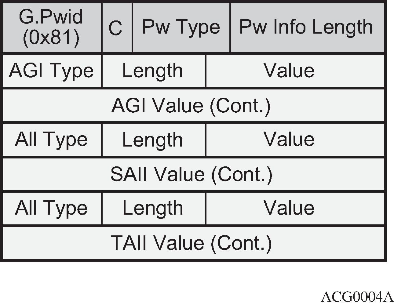
The Attachment Group Identifier (AGI) is not used in dynamic MS-PW signaling. In VPLS, it typically carries the instance identifier. It is zero in dynamic MS-PWs.
The SAII and TAII (or pseudowire end-point identifiers) are encoded in FEC129 and can have two different formats: AII Type 1 or AII Type 2.
AII Type 1 is composed of a fixed 32-bit value unique on the local PE. This AII type is used by VPLS when BGP-AD is needed.
AII type 2 format shows the AII type 2 format. AII type 2 is composed of global-ID:prefix: attachment-circuit-ID (GID:prefix:AC-ID) and allows for summarization, thereby enhancing scalability in large networks. The GID is normally derived from the AS number, the prefix from the node system address, and the AC-ID is the local pseudowire end-point identifier. The combination of the three identifiers gives us a globally unique 96-bit AII value. In general, the same global ID and prefix are assigned for all ACs belonging to the same Terminating PE (T-PE). This is not a strict requirement though.
Figure 2. AII type 2 format 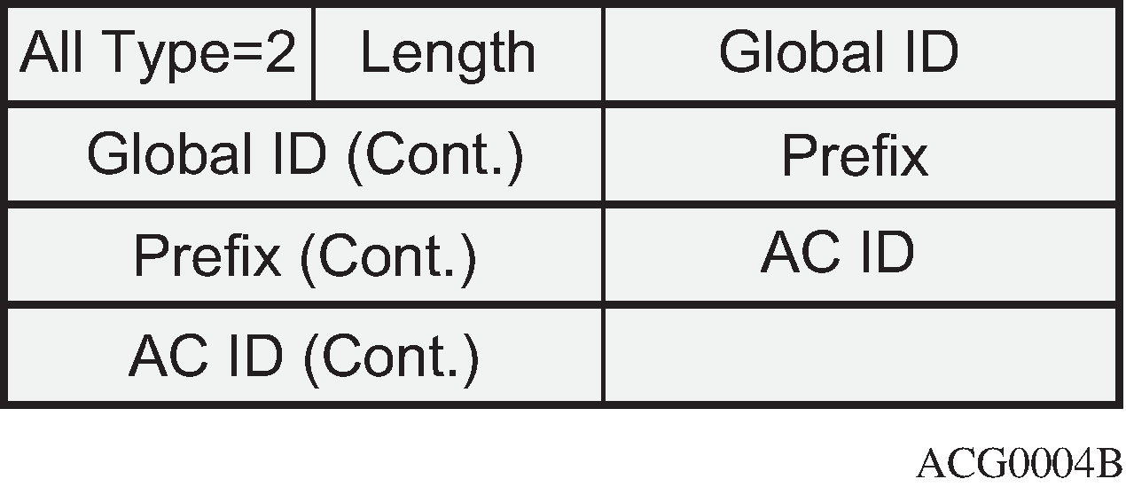
A MS-PW routing table must be built in all the T-PEs and S-PEs through one of the following two mechanisms:
Multi-protocol BGP (MP-BGP), using a dedicated NLRI and SAFI (pseudowire routing SAFI=6, with AFI=25 for L2-VPN). The FEC129 AII Type 2 global values are mapped in the pseudowire routing NLRI and advertised by BGP. SR OS supports an NLRI comprising a Length, RD, Global ID, and 32-bit prefix, that is, the AC ID is not included in the advertised NLRI. The AC ID is not included as indicated in RFC 7267 because the source T-PE knows by provisioning the AC ID on the terminating T-PE to use in signaling. Therefore, there is no need to advertise a ‟fully qualified” 96-bit address on a per pseudowire attachment circuit basis. Only the T-PE Global ID, Prefix, and prefix length need to be advertised as part of well-known BGP procedures. This also minimizes the amount of routing information that is advertised in BGP to only what is necessary to reach the far-end T-PE. Pseudowire routing NLRI (the AC ID is always zero) shows the MS-PW routing NLRI:
Figure 3. Pseudowire routing NLRI (the AC ID is always zero) 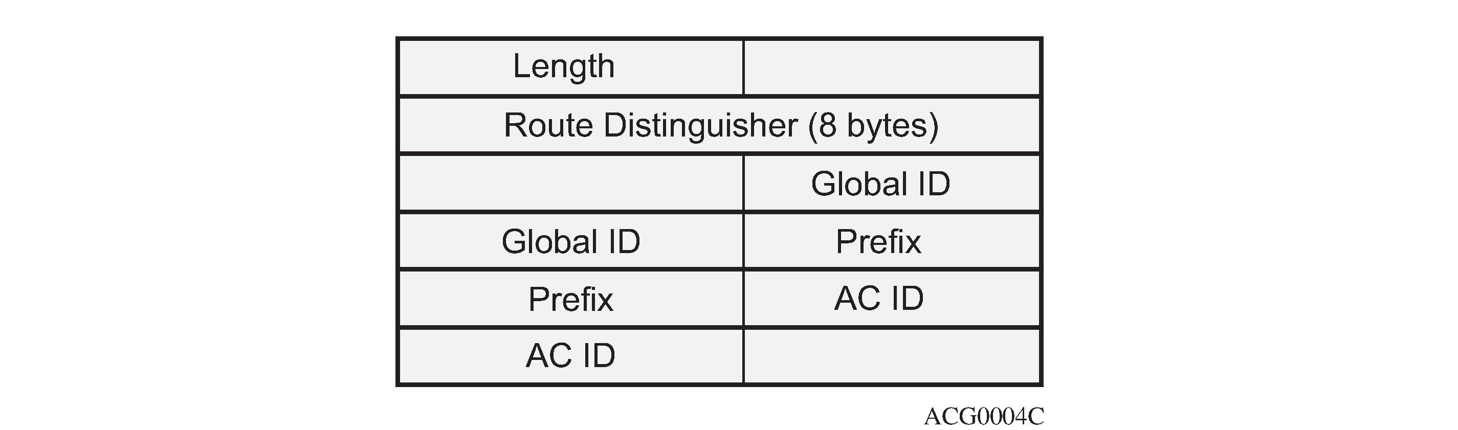
Static routes, configurable via CLI
Once the MS-PW routing table is populated, Targeted LDP (T-LDP) will make use of it to signal the MS-PW all the way from the originating T-PE to the terminating T-PE as well as in the reverse direction. The following methods will be used:
At the originating T-PE, a longest-match lookup will be performed in the pseudowire routing table for the configured TAII. Based on the lookup outcome, a label mapping message will be sent to the Next Signaling Hop (NSH).
Note:The ‟originating T-PE” will be the T-PE initiating the MS-PW signaling. See the Active/passive signaling and auto-configuration section for further information.
At the intermediate S-PEs and destination T-PE, a longest-match lookup between the TAII Type 2 included in the T-LDP signaling message and entries installed in the pseudowire routing table will be performed.
Alternatively to the pseudowire routing table lookup, T-LDP can also use explicit routing, as per section 7.4.2 of RFC 7267. If that is the case, a ‟path” must be configured on the T-PEs. The originating T-PE will include an Explicit Route Object (ERO) in the T-LDP label mapping, containing all the S-PE hops specified in the configured path. Each S-PE along the path will remove its own entry from the ERO and will forward the label mapping message to the next hop.
SR OS supports the information model and all the previously described methods:
Dynamic placement through MP-BGP, with the pseudowire routing NLRI
Static routes
Explicit paths
In addition to the above, the following features are supported on dynamic MS-PW:
Auto-configuration of spoke SDPs at T-PE (if enabled on a T-PE, there is no need for configuring the TAII of the remote T-PE, see Active/passive signaling and auto-configuration. The auto-configuration is typically used in hub-and-spoke scenarios. The TAII would only be configured on the spoke T-PE whereas the TAII would be automatically provisioned on the hub T-PE if the auto-config parameter is added.
OAM using virtual circuit connectivity verification vccv-ping and vccv-trace
Pseudowire redundancy
Control word
Hash label
Standby-signaling-master and standby-signaling-slave commands
Filters
Configuration
The following flowchart in Configuration flowchart shows the configuration process to be followed when setting up MS-PW routing. Base IGP and MPLS configuration is assumed to be in place before these configuration tasks can be carried out.
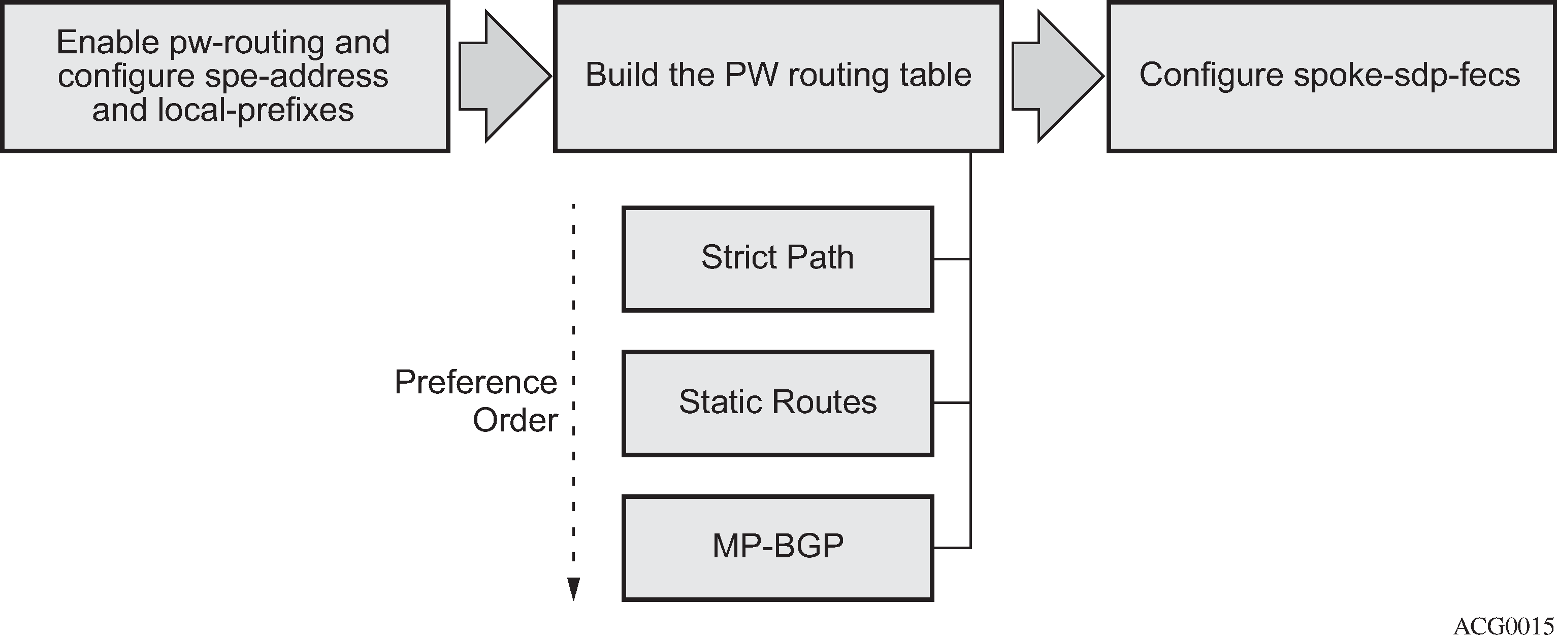
The following subsections review these three steps, including all the options in detail.
Pseudowire routing enablement
The first step in the configuration is to enable pw-routing and configure the required pseudowire routing basic parameters: the spe-address (in S-PEs and T-PEs) and the local-prefix/prefixes (only required in T-PEs). The following CLI examples show the configuration of the spe-address and local-prefixes.
# on PE-1:
configure
    service
        pw-routing
            spe-address 65536:192.0.2.1
            local-prefix 65536:192.0.2.11 create
                advertise-bgp route-distinguisher 65536:11 community 65535:11
            exit
            local-prefix 65536:192.0.2.12 create
                advertise-bgp route-distinguisher 65536:12 community 65535:12
            exit
        exit
In order to enable support for MS-PW routing on an SR OS router, a single, globally unique, S-PE ID (known as the spe-address) is first configured in the config>service>pw-routing context on each SR OS router to be used as a T-PE or S-PE. The S-PE address has the format global-id:prefix. It is not possible to configure any local prefixes used for pseudowire routing or to configure spoke SDPs using dynamic MS-PWs at a T-PE, unless an S-PE address has already been configured. The S-PE address is used as the address of a node when populating the switching point TLV in the LDP label mapping message and the pseudowire status notification sent for faults at an S-PE. The following output shows the spe-address configuration format:
*A:PE-1# configure service pw-routing spe-address ?
  - no spe-address
  - spe-address <global-id:prefix>

 <global-id:prefix>   : <global-id>:{<prefix>|<ipaddress>}
                        global-id - [1..4294967295]
                        prefix    - [1..4294967295]
                        ipaddress - a.b.c.d
Where:
<global-id> is normally the 2 or 4-byte ASN identifying the network (although nothing prevents the operator from configuring any value here)
<prefix> is normally the system address of the node (although any value in IP address or decimal format can be used)
If an S-PE is capable of dynamic MS-PW signaling, but is not assigned with an S-PE address, then on receiving a dynamic MS-PW label mapping message, the S-PE will return a label release with the "LDP_RESOURCES_UNAVAILABLE" (0x38)" status code. The S-PE address cannot be changed unless the dynamic MS-PW configuration is completely removed; therefore Nokia recommends to configure the spe-address carefully and keep it for the life of the services.
The second basic pw-routing context parameter is the local-prefix:
*A:PE-1# configure service pw-routing local-prefix ?
  - local-prefix <local-prefix> [create]
  - no local-prefix <local-prefix>

 <local-prefix>       : <global-id>:<ip-addr>|<raw-prefix>
                        ip-addr      - a.b.c.d
                        raw-prefix   - [1..4294967295]
                        global-id    - [1..4294967295]

 [no] advertise-bgp   - Configure BGP advertisement
One or more local (Layer 2) prefixes (up to a maximum of 16), which are formatted in the style of <global-id>:<ipv4-address>, are supported. A local prefix identifies a T-PE in the pseudowire routing domain. When using explicit paths or static routes, the definition of the local-prefixes without any further attribute is enough. However, when BGP is used, the advertise-bgp parameter along with a Route Distinguisher (RD) value and an optional BGP community is required.
A:PE-1# configure service pw-routing local-prefix 65536:192.0.2.11 advertise-bgp ?
  - advertise-bgp route-distinguisher <rd> [community <community>]
  - no advertise-bgp route-distinguisher <rd>

 <rd>                 : <ip-addr:comm-val>|<2byte-asnumber:ext-comm-val>|
                                           <4byte-asnumber:comm-val>
                        ip-addr        - a.b.c.d
                        comm-val       - [0..65535]
                        2byte-asnumber - [1..65535]
                        ext-comm-val   - [0..4294967295]
                        4byte-asnumber - [1..4294967295]
 <community>          : <asnumber:comm-val>
                        asnumber - [1..65535]
                        comm-val - [0..65535]
Up to four unique RDs (and communities) can be configured per each local prefix. Different RDs for the same prefix allow the operator to advertise the same prefix coming from up to four different Next Signaling Hops (NSHs). Route Reflectors (RRs) would reflect the four routes in that case, whereas only one would be reflected should the same RD be used.
*A:PE-1>config>service>pw-routing>local-prefix# info
----------------------------------------------
                advertise-bgp route-distinguisher 400:20
                advertise-bgp route-distinguisher 500:3
                advertise-bgp route-distinguisher 600:300
                advertise-bgp route-distinguisher 65536:11 community 65535:11
*A:PE-1>config>service>pw-routing>local-prefix# advertise-bgp route-distinguisher 700:100
MINOR: SVCMGR #6072 Maximum number of RD's has been reached
For each local prefix, BGP then advertises each global ID/prefix tuple and unique RD and community (if configured) using the MS-PW NLRI, based on the aggregated FEC129 AII Type 2 and the Layer 2 VPN/PW routing AFI/SAFI 25/6, to each BGP neighbor, subject to local BGP policies.
Building the pseudowire routing table
Once the S-PE address and the local prefixes have been configured and before configuring the Epipe service itself on the T-PE nodes, we need to populate the pseudowire routing table in all the participating T-PE and S-PE nodes, so that T-LDP knows what the Next Signaling Hop (NSH) is and sends LDP label mapping messages.
The pseudowire routing table will be populated with local prefixes, static routes, and BGP routes, where the static routes have preference over the BGP-learned routes. The pseudowire routing table can be overridden by the explicit paths, should the operator want to configure them. Therefore, when T-LDP signals an LDP Label Mapping for a TAII, it will:
First check if there is an explicit path configured for that spoke-SDP FEC.
Otherwise, it will look up the TAII prefix into the pseudowire routing table, where static routes take precedence over BGP routes.
An aggregation scheme, similar to that used for classless IPv4 addresses, can be employed in the pseudowire routing table, where a longest match is used to find a route. Except for the default pseudowire route, which is encoded with a zero mask, masks included in the pw-routing table are:
/64 for regular prefixes, including a global ID and prefix (as previously mentioned; the AC-ID is not included in the BGP NLRI).
/96 for local prefixes, including the AC-ID, as well as global-id and prefix.
Each S-PE and T-PE must have a pseudowire routing table that contains a reference to the T-LDP session to use to signal to a set of next hop S-PEs to reach a T-PE (or the T-PE if that is the next hop). For Epipes, this table contains aggregated AII Type 2 FECs and may be populated with routes that are learned through MP-BGP or that are statically configured.
Explicit paths
A set of default explicit routes to a remote T-PE prefix may be configured on a T-PE under config>services>pw-routing using the path name command. Explicit paths are used to populate the explicit route TLV used by MS-PW T-LDP signaling. Only strict (fully qualified) explicit paths are supported. It is possible to configure explicit paths independently of the configuration of BGP or static routing.
The following CLI excerpt shows an explicit path example for a MS-PW following the PE-1–PE-3–PE-5–PE-2 path (see the example topology in Intra-AS MS-PW example topology). The IP addresses are the system addresses of all the S-PE and T-PE along the path (except for PE-1).
# on PE-1:
configure
    service
        pw-routing
            path "path-1" create
                hop 1 192.0.2.3
                hop 2 192.0.2.5
                hop 3 192.0.2.2
                no shutdown
            exit
Static routes
In addition to support for BGP routing, static MS-PW routes may also be configured using the config services pw-routing static-route command. Each static route comprises of the target T-PE global ID and prefix, and the IP address of the T-LDP session to the next hop S-PE or T-PE that should be used:
*A:PE-1# configure service pw-routing static-route ?
  - no static-route <route-name>
  - static-route <route-name>

 <route-name>         : <global-id>:<prefix>:<next-hop-ip_addr>
                        global-id      - 0..4294967295
                        prefix         - a.b.c.d|0..4294967295
                        ip_addr        - a.b.c.d
If a static route <global-id>:<prefix> is set to 0, then this represents the default route.
# on PE-1:
configure
    service
        pw-routing
            static-route 0:0.0.0.0:192.0.2.3
            static-route 0:0.0.0.0:192.0.2.4
Even though several default routes can be configured, only one default route is added to the PW routing table. The following command shows the PW routing table content where only one default route (out of the two previously configured ones) is added. The default route added to the PW routing table is the first valid route added to the configuration.
*A:PE-1# show service pw-routing route-table all-routes

===============================================================================
Service PW L2 Routing Information
===============================================================================
AII-Type2/Prefix-Len                           Next-Hop       Owner  Age
 Route-Distinguisher                            Community      Best
-------------------------------------------------------------------------------
0:0.0.0.0:0/0                                  192.0.2.3      static 00h00m11s
 0:0                                            0:0            yes
---snip---
If a static route exists to a T-PE, then this is used in preference to any BGP route that may exist.
BGP routes
As already mentioned, the dynamic advertisement of the PW routes is enabled for each prefix and RD using the advertise-bgp command in the config>services>pw-routing>local-prefix context. A BGP export policy is required in order to export MS-PW routes in MP-BGP. This can be done using a default policy matching all the MS-PW routes, such as the following:
# on PE-1:
configure
    router
        autonomous-system 65536
        policy-options
            begin
            policy-statement "export_ms-pw"
                entry 10
                    from
                        family ms-pw
                    exit
                    action accept
                        origin igp
                    exit
                exit
            exit
            commit
        exit
        bgp
            enable-peer-tracking
            rapid-withdrawal
            group "region"
                family ms-pw
                export "export_ms-pw"
                peer-as 65536
                neighbor 192.0.2.3
                exit
                neighbor 192.0.2.4
                exit
            exit
        exit
MS-PW routes advertised/received can be debugged and shown on the log sessions (debug router bgp update). A dedicated MS-PW address family and NLRI are used to distribute the MS-PW prefixes. The following BGP update is sent by PE-1 to PE-3:
# on PE-1:
2 2021/03/03 08:55:53.651 UTC MINOR: DEBUG #2001 Base Peer 1: 192.0.2.3
"Peer 1: 192.0.2.3: UPDATE
Peer 1: 192.0.2.3 - Send BGP UPDATE:
    Withdrawn Length = 0
    Total Path Attr Length = 51
    Flag: 0x90 Type: 14 Len: 26 Multiprotocol Reachable NLRI:
        Address Family MSPW
        NextHop len 4 NextHop 192.0.2.1
        [MSPW] rd: 65536:12, global-id 65536, prefix 192.0.2.12,  ac-id 0, preflen 128
    Flag: 0x40 Type: 1 Len: 1 Origin: 0
    Flag: 0x40 Type: 2 Len: 0 AS Path:
    Flag: 0x40 Type: 5 Len: 4 Local Preference: 100
    Flag: 0xc0 Type: 8 Len: 4 Community:
        65535:12
"
MS-PW BGP routes can also be displayed in the pseudowire routing table along with the static routes and the local prefixes.
*A:PE-1# show service pw-routing route-table

===============================================================================
Service PW L2 Routing Information
===============================================================================
AII-Type2/Prefix-Len                           Next-Hop       Owner  Age
 Route-Distinguisher                            Community      Best
-------------------------------------------------------------------------------
0:0.0.0.0:0/0                                  192.0.2.3      static 00h05m58s
 0:0                                            0:0            yes
65536:192.0.2.11:0/64                          192.0.2.1      local  00h09m53s
 0:0                                            0:0            yes
65536:192.0.2.11:0/64                          192.0.2.1      local  00h09m53s
 65536:11                                       65535:11       yes
65536:192.0.2.12:0/64                          192.0.2.1      local  00h09m53s
 0:0                                            0:0            yes
65536:192.0.2.12:0/64                          192.0.2.1      local  00h09m53s
 65536:12                                       65535:12       yes
65536:192.0.2.21:0/64                          192.0.2.3      bgp    00h02m29s
 65536:21                                       65535:11       yes
65536:192.0.2.22:0/64                          192.0.2.4      bgp    00h02m44s
 65536:22                                       65535:12       yes
-------------------------------------------------------------------------------
Entries found: 7
===============================================================================
If there are two (or more) equal cost BGP MS-PW routes with identical <global-ID:prefix> and different RDs in the RIB, they are both tagged as best/used and both will be added to the pseudowire routing table; however, only the one with a higher RD will be shown as ‟Best” and as a result of that, only that one will be used by T-LDP for the NSH.
The pw-routing context on PE-2 contains the following advertise-bgp entries with different RDs for local-prefix 65536:192.0.2.2:
# on PE-2:
configure
    service
        pw-routing
            local-prefix 65536:192.0.2.2 create
                advertise-bgp route-distinguisher 65536:21 community 65535:11
                advertise-bgp route-distinguisher 65536:22 community 65535:12
            exit
The following CLI output shows an example of two equal cost MS-PW routes. The route 65536:192.0.2.2 with RD 65536:21 and next-hop 192.0.2.3 is tagged as best and used; the route with RD 65536:22 and next-hop 192.0.2.4 is also best and used (u*>).
*A:PE-1# show router bgp routes ms-pw aii-type2 65536:192.0.2.2:0
===============================================================================
 BGP Router ID:192.0.2.1        AS:65536       Local AS:65536
===============================================================================
 Legend -
 Status codes  : u - used, s - suppressed, h - history, d - decayed, * - valid
                 l - leaked, x - stale, > - best, b - backup, p - purge
 Origin codes  : i - IGP, e - EGP, ? - incomplete

===============================================================================
BGP MSPW Routes
===============================================================================
Flag  Network                 RD
      Nexthop                 AII-Type2/Preflen
      As-Path
-------------------------------------------------------------------------------
u*>i  65536:192.0.2.2         65536:21
      192.0.2.3               65536:192.0.2.2:0/64
      No As-Path
*i    65536:192.0.2.2         65536:21
      192.0.2.4               65536:192.0.2.2:0/64
      No As-Path
u*>i  65536:192.0.2.2         65536:22
      192.0.2.4               65536:192.0.2.2:0/64
      No As-Path
*i    65536:192.0.2.2         65536:22
      192.0.2.3               65536:192.0.2.2:0/64
      No As-Path
-------------------------------------------------------------------------------
Routes : 4
===============================================================================
However, only the one with RD 65536:22 (higher RD) is added as ‟Best” to the pseudowire routing table and T-LDP will use 192.0.2.4 as the NSH:
*A:PE-1# show service pw-routing route-table all-routes

===============================================================================
Service PW L2 Routing Information
===============================================================================
AII-Type2/Prefix-Len                           Next-Hop       Owner  Age
 Route-Distinguisher                            Community      Best
-------------------------------------------------------------------------------
---snip---
65536:192.0.2.2:0/64                           192.0.2.3      bgp    00h01m13s
 65536:21                                       65535:11       no
65536:192.0.2.2:0/64                           192.0.2.4      bgp    00h01m31s
 65536:22                                       65535:12       yes
---snip---
In the preceding example, the routes have different RDs, but that need not be the case. When the originating T-PE or any intermediate S-PE receives two (or more) equal cost MS-PW routes with the same RD but from different Next-Hops (NHs), all the MS-PW routes will be added to the MS-PW routing table as ‟Best”.
In case multiple equal-cost MS-PW routes are available, T-LDP will pick up the NSH out of an ECMP hashing algorithm applied to the <global-ID:prefix:AC-ID> for the SAII and the TAII of the pseudowires pointing at the same prefix. The output of that hashing algorithm will determine what the NSH will be for a spoke-SDP FEC.
When path diversity for an active and a standby pseudowire (hot standby pseudowire redundancy) is desired and the two pseudowires of the same Epipe endpoint are pointing at the same remote <global-ID:prefix> coming from two different NHs, the operator has to make sure T-LDP chooses a different NSH for the standby pseudowire. Only in that case, hot standby pseudowire redundancy can be achieved. As a rule of thumb, if the SAII/TAII of the active and standby pseudowires are separated by 16 or more AC-ID values, T-LDP will select a different NSH for both pseudowires.
For example:
Given the following SAII/TAII AC-ID values for the active/standby pseudowires on the originating T-PE, T-LDP will select the same NSH:
Active pseudowire: saii-type2 — 65536:192.0.2.1:1, taii-type2 — 65536:192.0.2.2:1
Standby pseudowire: saii-type2 — 65536:192.0.2.1:2, taii-type2 — 65536:192.0.2.2:2
However, the following SAII/TAII AC-ID values for the active/standby pseudowires on the originating T-PE will allow the ECMP hashing algorithm to make T-LDP select different NSHs for the active and the standby pseudowires:
Active pseudowire: saii-type2 — 65536:192.0.2.1:1, taii-type2 — 65536:192.0.2.2:1
Standby pseudowire: saii-type2 — 65536:192.0.2.1:16, taii-type2 — 65536:192.0.2.2:16
Other AC-ID values greater than 16 (for the standby pseudowire) would also have achieved next hop diversity.
Configuring dynamic pseudowires on the T-PEs
Before any LDP signaling can take place, T-LDP sessions must be explicitly configured on T-PEs and S-PEs.
One or more spoke-SDPs may be configured for distributed Epipe VLL services. Dynamic MS-PWs use FEC129 (also known as the Generalized ID FEC) with AII Type 2 to identify the pseudowire, as opposed to FEC128 (also known as the PW ID FEC) used for traditional single segment pseudowires and for pseudowire switching. FEC129 spoke-SDPs are configured under the spoke-sdp-fec command in the CLI. Spoke-SDP FECs (or FEC129 spoke-SDPs) are by default FEC type 129 and AII type 2. Spoke-SDP FECs can be part of an endpoint and even an Inter-Chassis Backup (ICB) pseudowire.
*A:PE-1# configure service epipe "Epipe2" spoke-sdp-fec ?
  - no spoke-sdp-fec <spoke-sdp-fec-id>
  - spoke-sdp-fec <spoke-sdp-fec-id> [fec <fec-type>] [aii-type <aii-type>] [create]
  - spoke-sdp-fec <spoke-sdp-fec-id> no-endpoint
  - spoke-sdp-fec <spoke-sdp-fec-id> [fec <fec-type>] [aii-type <aii-type>] [create]
                  endpoint <name> [icb]

 <spoke-sdp-fec-id>   : [1..4294967295]
 <fec-type>           : [129..130]
 <aii-type>           : [1..2]
 <name>               : [32 chars max]
 <icb>                : keyword - configure spoke-sdp as inter-chassis backup
FEC129 AII Type 2 uses a SAII and a TAII to identify the ends of a PW at the T-PE. The SAII identifies the local end, while the TAII identifies the remote end. The SAII and TAII are each structured as follows:
Global ID: this is a 4-byte identifier that uniquely identifies an operator or the local network. Normally, this matches the ASN
Prefix: a 4-byte prefix, which should correspond to one of the local prefixes assigned under pw-routing
AC ID: a 4-byte identifier for this end of the PW. This should be locally unique within the scope of the global-id:prefix
In terms of the SDP tunnel being used by each spoke-SDP FEC, PW routing chooses the MS-PW path in terms of the sequence of S-PEs to use to reach a T-PE. It does not select the SDP to use on each hop, which is instead determined at signaling time. When a label mapping is sent for a PW segment, an LDP SDP will be used to reach the next-hop S-PE/T-PE, if such an SDP exists. If not, and an RFC 3107 labeled BGP SDP is available, then that will be used. Otherwise, the label mapping will fail and a label release will be sent.
The RSVP SDPs might be picked at the T-PE through the use of pw-template <policy-id> [use-provisioned-sdp], however there is no way to select an RSVP SDP on an S-PE.
The following CLI output shows one example of two spoke-SDP FECs belonging to an endpoint:
# on PE-1:
configure
    service
        pw-template 1 name "PW1" create
            controlword
        exit
        epipe 2 name "Epipe2" customer 1 create
            description "ms-pw epipe with bgp - using 2 prefixes"
            endpoint "CORE" create
                description "endpoint for epipe A/S PW redundancy"
                revert-time 10
                standby-signaling-master
            exit
            sap 1/1/4:2 create
            exit
            spoke-sdp-fec 21 fec 129 aii-type 2 create endpoint CORE
                precedence primary
                pw-template-bind 1
                saii-type2 65536:192.0.2.11:1
                taii-type2 65536:192.0.2.21:1
                no shutdown
            exit
            spoke-sdp-fec 22 fec 129 aii-type 2 create endpoint CORE
                pw-template-bind 1
                saii-type2 65536:192.0.2.12:1
                taii-type2 65536:192.0.2.22:1
                no shutdown
            exit
            no shutdown
        exit
The following options are available in the spoke-sdp-fec context:
*A:PE-1# configure service epipe "Epipe2" spoke-sdp-fec ?
  - no spoke-sdp-fec <spoke-sdp-fec-id>
  - spoke-sdp-fec <spoke-sdp-fec-id> [fec <fec-type>] [aii-type <aii-type>] [create]
  - spoke-sdp-fec <spoke-sdp-fec-id> no-endpoint
  - spoke-sdp-fec <spoke-sdp-fec-id> [fec <fec-type>] [aii-type <aii-type>] [create]
                                     endpoint <name> [icb]

 <spoke-sdp-fec-id>   : [1..4294967295]
 <fec-type>           : [129..130]
 <aii-type>           : [1..2]
 <name>               : [32 chars max]
 <icb>                : keyword - configure spoke-sdp as inter-chassis backup

 [no] auto-config     - Configure auto-configuration
 [no] path            - Configure path-name
 [no] precedence      - Configure precedence
 [no] pw-template-bi* - Configure Pseudo-Wire template-binding policy
 [no] retry-count     - Configure retry count
 [no] retry-timer     - Configure retry timer
 [no] saii-type2      - Configure Source Attachment Individual Identifier (SAII)
 [no] shutdown        - Administratively enable/disable the spoke SDP FEC binding
      signaling       - Configure Spoke-SDP FEC signaling
 [no] standby-signal* - Enable PW standby-signaling slave
 [no] taii-type2      - Configure Target Attachment Individual Identifier (TAII)
Active/passive signaling and auto-configuration
When an MS-PW is signaled, each T-PE might independently initiate signaling of the MS-PW. This could result in a different path being used in each direction of the PW. To avoid this situation, one of the T-PEs will start the PW signaling (active role), while the other T-PE waits to receive the LDP label mapping message before sending the LDP label mapping message for the reverse direction of the PW (passive role).
Debugging for LDP messages is enabled on PE-2, as follows:
# on PE-2:
debug
    router "Base"
        ldp
            peer 192.0.2.5
                packet
                    init detail
                    label detail
                exit
            exit
            peer 192.0.2.6
                packet
                    init detail
                    label detail
                exit
            exit
        exit
By default, the T-PE with SAII>TAII will have the active role and will send the label mapping first. When spoke-SDP FEC 21 is first disabled, and then enabled, PE-2 sends a label mapping to PE-5 first (message 77 in following output). Afterward, it receives a label mapping packet from PE-5 (message 78).
# on PE-2:
configure
    service
        epipe "Epipe2"
            spoke-sdp-fec 21
                shutdown
                no shutdown
33 2021/03/03 09:06:57.536 UTC MINOR: DEBUG #2001 Base LDP
"LDP: LDP
Send Label Mapping packet (msgId 146) to 192.0.2.5:0
Protocol version = 1
Label 524277 advertised for the following FECs
Service FEC GENPWE3: ENET(5)
AGI = type: 1, len: 8, val: 00:00:00:00:00:00:00:00
SAII = T: 2, L: 12, Global-id: 65536, Prefix: 192.0.2.21, AcId: 1
TAII = T: 2, L: 12, Global-id: 65536, Prefix: 192.0.2.11, AcId: 1
Group ID = 0 cBit = 1
Interface parameter Mtu = 1500
Interface parameter VCCV = 0x306
PW status bits = 0x0
"
34 2021/03/03 09:06:57.550 UTC MINOR: DEBUG #2001 Base LDP
"LDP: LDP
Recv Label Mapping packet (msgId 154) from 192.0.2.5:0
Protocol version = 1
Label 524277 advertised for the following FECs
Service FEC GENPWE3: ENET(5)
AGI = type: 1, len: 8, val: 00:00:00:00:00:00:00:00
SAII = T: 2, L: 12, Global-id: 65536, Prefix: 192.0.2.11, AcId: 1
TAII = T: 2, L: 12, Global-id: 65536, Prefix: 192.0.2.21, AcId: 1
Group ID = 0 cBit = 1
Interface parameter Mtu = 1500
Interface parameter VCCV = 0x106
PW status bits = 0x18
Switching hop: System = 192.0.2.3, Remote System = 192.0.2.1
previous segment fec AGI = type: 1, len: 8, val: 00:00:00:00:00:00:00:00
SAII = T: 2, L: 12, Global-id: 65536, Prefix: 192.0.2.11, AcId: 1
TAII = T: 2, L: 12, Global-id: 65536, Prefix: 192.0.2.21, AcId: 1
S-PE = T: 2, L: 12, Global-id: 65536, Prefix: 192.0.2.3, AcId: 0
Switching hop: System = 192.0.2.5, Remote System = 192.0.2.3
previous segment fec AGI = type: 1, len: 8, val: 00:00:00:00:00:00:00:00
SAII = T: 2, L: 12, Global-id: 65536, Prefix: 192.0.2.11, AcId: 1
TAII = T: 2, L: 12, Global-id: 65536, Prefix: 192.0.2.21, AcId: 1
S-PE = T: 2, L: 12, Global-id: 65536, Prefix: 192.0.2.5, AcId: 0
"
For the other T-PE, it is the other way round. PE-1 receives a label mapping packet first before it sends a label mapping packet back.
This default behavior can be modified by the signaling command. When set to master, the T-PE will send a label mapping message regardless of the SAII and TAII. By default the parameter is set to auto (which means the T-PE will trigger label mapping if SAII>TAII).
*A:PE-1# configure service epipe "Epipe2" spoke-sdp-fec 21 signaling ?
  - signaling <signaling>

 <signaling>          : auto|master
# on PE-1:
configure
    service
        epipe "Epipe2"
            spoke-sdp-fec 21
                shutdown
                signaling master
                no shutdown
The MS-PW routing implementation on SR OS supports single-sided auto-provisioning. This allows it to have ‟hub” T-PEs where the TAII is not required to be configured and as such simplifies the provisioning. In this case, the spoke T-PE PWs would be configured with specific SAII and TAII as well as signaling master, whereas the hub T-PE PWs would be configured with only the SAII and the auto-config parameter. When the auto-config attribute is set for a spoke-SDP FEC, the T-PE always passively waits for the label mapping to be received before issuing a label mapping message (because it does not know the TAII beforehand). This is a CLI example for a hub T-PE spoke-SDP FEC:
# on PE-2:
configure
    service
        epipe "Epipe2"
            spoke-sdp-fec 21 fec 129 aii-type 2 create
                auto-config
                precedence primary
                pw-template-bind 1
                saii-type2 65536:192.0.2.21:1
                no shutdown
            exit
Spoke-SDP FEC timers
MS-PW routing provides a few timers that can be configured at the global pw-routing level or at each specific spoke-SDP FEC level:
# on PE-1:
configure
    service
        pw-routing
            boot-timer 20
            retry-timer 40
            retry-count 50
# on PE-1:
configure
    service
        epipe "Epipe2"
            spoke-sdp-fec 21
                retry-timer 10
                retry-count 10
Where:
Boot-timer (the default is 10 seconds with values 0 — 600 seconds allowed): Configures a hold-off timer for MS-PW routing advertisements and signaling that is used at boot time. This timer helps to make sure all the network infrastructure is up and running before setting up the PWs.
Retry-timer (the default is 30 seconds with values 10 — 480 seconds allowed): The exponential back-off timer that determines the interval between consecutive retries to re-establish a spoke-SDP. The configured value gives the initial retry time. The attempt fails if a label withdrawal is received. If configured at global and spoke-SDP FEC level, the latter overrides the value set by the global settings.
Retry-count (the default 30 with values 10 — 10000): Specifies the number of attempts the system should make to re-establish the spoke-SDP after it has failed. After each successful attempt, the counter is reset to zero. When the specified number is reached, no more attempts are made and the spoke-SDP is put into the disabled state. Use the no shutdown command to bring up the path after the retry limit is exceeded. It is present at the PW routing level as well as the spoke-SDP FEC level. If configured at global and spoke-SDP FEC level, the latter overrides the value set by the global settings.
The usual endpoint level timers are also available for MS-PW routing:
Revert-time <time-value> | infinite (default is 0, values 0 — 600 sec): configures the time to wait before reverting to the primary spoke-SDP FEC.
Active-hold-delay (the default is 0, values 0 — 60 deci-seconds): It specifies that the node will delay sending the T-LDP status bits for VLL endpoint when the MC-LAG transitions the LAG subgroup which hosts the SAP from active to standby (MC-Ring or MC-APS are supported too) or when any object in the endpoint—SAP, ICB, or regular spoke SDP—transitions from up to down operational state. The active-hold-delay range starts from 1 (in units of deci-seconds) via CLI, and the only way to get the default value of zero is to use the no active-hold-delay command
Standby signaling
Just as with a regular endpoint with regular spoke-SDPs, there can also be standby-signaling-master and standby-signaling-slave parameters for spoke-SDP FECs.
The standby-signaling-master command is configured in the endpoint context and makes sure that standby signaling (T-LDP PW status bits 0x20) is sent for the selected standby PW.
# on PE-1:
configure
    service
        epipe "Epipe2"
            endpoint "CORE"
                standby-signaling-master
It is not allowed to add a SAP associated to an endpoint configured as standby-signaling-master to an Epipe.
*A:PE-1>config>service>epipe# sap 1/1/4:2 endpoint "CORE" create
MINOR: SVCMGR #6025 The endpoint has standby-signaling-master configured
The standby-signaling-slave can be configured at endpoint or spoke-SDP FEC level.
# at endpoint on PE-1:
configure
    service
        epipe "Epipe2"
            endpoint "CORE"
                no standby-signaling-master
                standby-signaling-slave
# at spoke-SDP FEC on PE-1:
configure
    service
        epipe "Epipe2"
            spoke-sdp-fec 21
                standby-signaling-slave
When standby-signaling-slave is configured, the node will block the transmit forwarding direction of a spoke-SDP based on the PW standby bit received from a T-LDP peer.
Spoke-SDP FEC templates and filters
PW templates are the way to configure the control word for this type of PW as well as ingress/egress filters (IPv4/MAC/IPv6). Filters are only supported on the T-PEs, because there is no provisioning of a PW template (or Epipe at all) on the S-PEs.
# on PE-1:
configure
    service
        pw-template 1 name "PW1" create
            controlword
            egress
                filter ip 1
            exit
        exit
        epipe 2 name "Epipe2" customer 1 create
---snip---
            spoke-sdp-fec 22 fec 129 aii-type 2 create endpoint CORE
                pw-template-bind 1
                saii-type2 65536:192.0.2.12:1
                taii-type2 65536:192.0.2.22:1
                no shutdown
            exit
PW template changes (just like for VPLS with BGP-AD or BGP-VPLS) are not automatically propagated. A tools perform command is provided to evaluate and distribute the changes at the service level to one or all the services that use that template (if the service ID is omitted, then all the services will be updated).
# on PE-1:
tools perform service id 2 eval-pw-template 1 allow-service-impact
Intra-AS MS-PW routing
This section provides a configuration example for an intra-AS scenario. Intra-AS MS-PW example topology shows the example topology that will be used for this section.
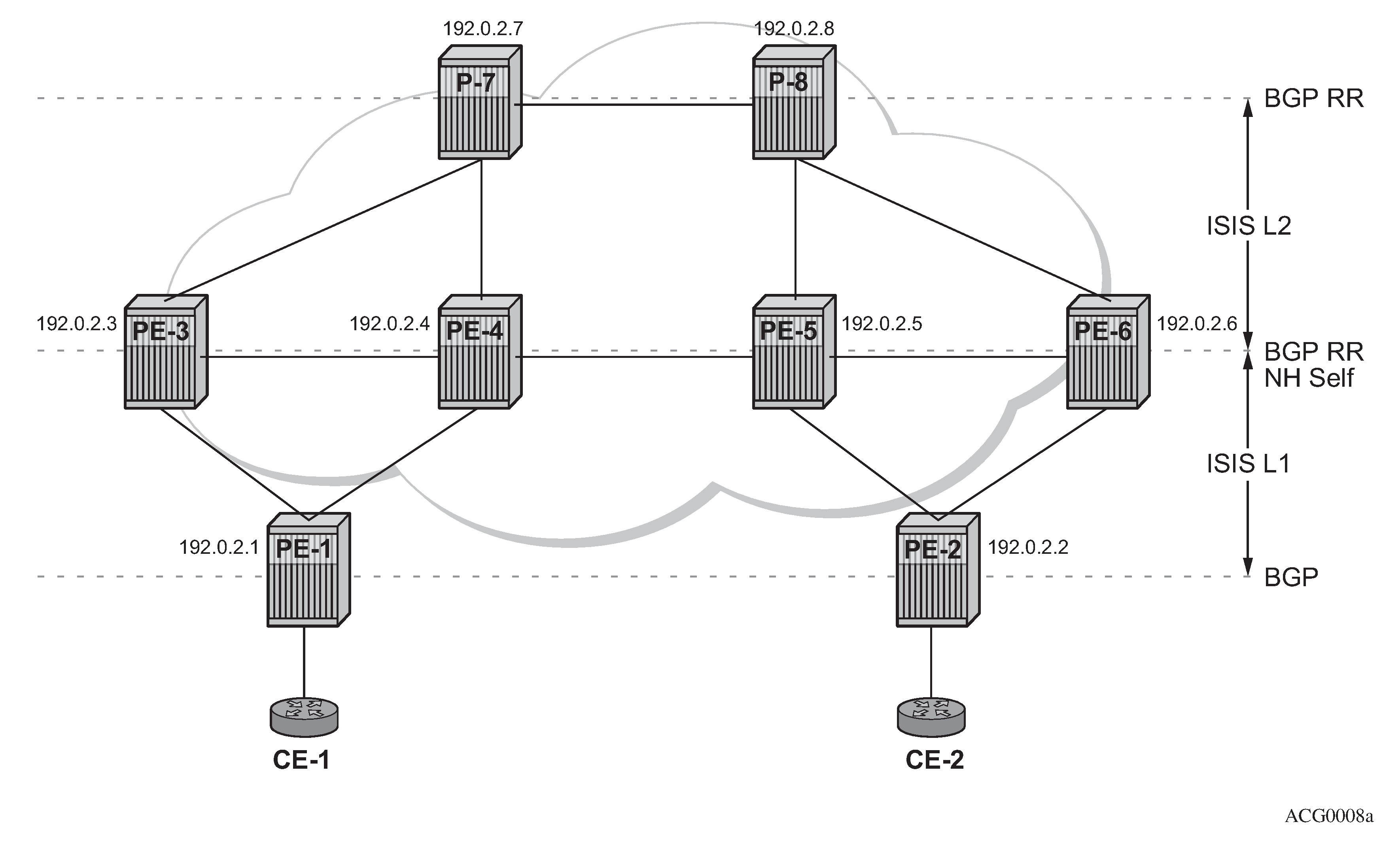
Multiple MS-PW routing Epipes are to be configured between PE-1 and PE-2, with PE-3, PE-4, PE-5, and PE-6 being S-PE routers. P-7 and P-8 are pure P routers from a data plane perspective.
All the PEs are pre-configured with IS-IS as the IGP, as shown in Intra-AS MS-PW example topology: PE-1 and PE-2 are level-1 routers, P-7 and P-8 are level-2 only routers and the rest of the routers are level-1/level-2. Link level LDP is also pre-configured on all the network interfaces and targeted LDP is configured between PE-1 and PE-3/PE-4, between PE-2 and PE-5/PE-6 and among PE-3, PE-4, PE-5, and PE-6. There are no targeted LDP sessions configured on P-7 and P-8.
As outlined in Configuration flowchart, the configuration is a three-step process where the pw-routing context is configured first, then the required configuration so that routing tables get populated accordingly and finally the services themselves.
MS-PW using BGP routing
In this subsection, Epipe 2 will be configured between PE-1 and PE-2, where T-LDP will use the BGP routes populated in the MS-PW routing table to signal the MS-PW.
The first step is the provisioning of the pw-routing context on all the T-PEs and S-PEs. The spe-address will be configured on all the T-PEs and S-PEs—all the routers except for P-7 and P-8—using the ASN as the global ID and the system address as the prefix. On PE-1 and PE-2, (only) the prefixes used for setting up Epipe 2 are configured. Two prefixes are configured per T-PE so that PW redundancy with path diversity for the standby PW can be carried out. The spe-address and local prefixes for the T-PEs are shown in the following CLI output. The advertise-bgp parameter is required because BGP is used here.
# on PE-1:
configure
    service
        pw-routing
            spe-address 65536:192.0.2.1
            local-prefix 65536:192.0.2.11 create
                advertise-bgp route-distinguisher 65536:11 community 65535:11
            exit
            local-prefix 65536:192.0.2.12 create
                advertise-bgp route-distinguisher 65536:12 community 65535:12
            exit
# on PE-2:
configure
    service
        pw-routing
            spe-address 65536:192.0.2.2
            local-prefix 65536:192.0.2.21 create
                advertise-bgp route-distinguisher 65536:21 community 65535:11
            exit
            local-prefix 65536:192.0.2.22 create
                advertise-bgp route-distinguisher 65536:22 community 65535:12
            exit
The second step is the configuration of BGP.
As shown in Intra-AS MS-PW example topology, BGP is enabled in all the routers. The middle routers (PE-3, PE-4 and PE-5, PE-6) are BGP RRs for PE-1 and PE-2 and they reflect MS-PW routes while changing the next-hop to their own system address. This is required so that T-LDP knows where to send the label mapping message for a particular prefix. P-7 and P-8 are regular RRs reflecting routes among all the S-PEs. The BGP configuration of PE-1, PE-3, PE-4, and P-7 is as follows. Similar commands are configured on the other PEs depending on their T-PE, S-PE, or RR function.
The T-PEs have dual-homed BGP sessions to the S-PEs. Example for PE-1:
# on PE-1:
configure
    router
        autonomous-system 65536
        policy-options
            begin
            policy-statement "export_ms-pw"
                entry 10
                    from
                        family ms-pw
                    exit
                    action accept
                        origin igp
                    exit
                exit
            exit
            commit
        exit
        bgp
            enable-peer-tracking
            rapid-withdrawal
            group "region"
                family ms-pw
                export "export_ms-pw"
                peer-as 65536
                neighbor 192.0.2.3
                exit
                neighbor 192.0.2.4
                exit
            exit
        exit
The S-PEs are reflecting routes and also changing the NH and local preference based on the communities accordingly, so that PW diversity can be ensured.
# on PE-3:
configure
    router
        autonomous-system 65536
        policy-options
            begin
            community "65535:11"
                members "65535:11"
            exit
            community "65535:12"
                members "65535:12"
            exit
            policy-statement "export_ms-pw_ABR-to-core"
                entry 10
                    from
                        protocol bgp
                        community "65535:11"
                        family ms-pw
                    exit
                    action accept
                        origin igp
                        local-preference 150
                        next-hop-self
                    exit
                exit
                entry 20
                    from
                        protocol bgp
                        community "65535:12"
                        family ms-pw
                    exit
                    action accept
                        origin igp
                        local-preference 100
                        next-hop-self
                    exit
                exit
            exit
            policy-statement "export_ms-pw_ABR-to-region"
                entry 10
                    from
                        protocol bgp
                        community "65535:11"
                        family ms-pw
                    exit
                    action accept
                        origin igp
                        local-preference 150
                        next-hop-self
                    exit
                exit
                entry 20
                    from
                        protocol bgp
                        community "65535:12"
                        family ms-pw
                    exit
                    action accept
                        origin igp
                        local-preference 100
                        next-hop-self
                    exit
                exit
            exit
            commit
        exit
        bgp
            rapid-withdrawal
            group "core"
                family ms-pw
                export "export_ms-pw_ABR-to-core"
                peer-as 65536
                neighbor 192.0.2.7
                exit
                neighbor 192.0.2.8
                exit
            exit
            group "region"
                family ms-pw
                cluster 3.3.3.3
                export "export_ms-pw_ABR-to-region"
                peer-as 65536
                enable-peer-tracking
                neighbor 192.0.2.1
                exit
            exit
The second S-PE to which PE-1 is connected has the following BGP configuration:
# on PE-4:
configure
    router
        autonomous-system 65536
        policy-options
            begin
            community "65535:11"
                members "65535:11"
            exit
            community "65535:12"
                members "65535:12"
            exit
            policy-statement "export_ms-pw_ABR-to-core"
                entry 10
                    from
                        protocol bgp
                        community "65535:12"
                        family ms-pw
                    exit
                    action accept
                        origin igp
                        local-preference 150
                        next-hop-self
                    exit
                exit
                entry 20
                    from
                        protocol bgp
                        community "65535:11"
                        family ms-pw
                    exit
                    action accept
                        origin igp
                        local-preference 100
                        next-hop-self
                    exit
                exit
            exit
            policy-statement "export_ms-pw_ABR-to-region"
                entry 10
                    from
                        protocol bgp
                        community "65535:12"
                        family ms-pw
                    exit
                    action accept
                        origin igp
                        local-preference 150
                        next-hop-self
                    exit
                exit
                entry 20
                    from
                        protocol bgp
                        community "65535:11"
                        family ms-pw
                    exit
                    action accept
                        origin igp
                        local-preference 100
                        next-hop-self
                    exit
                exit
            exit
            commit
        exit
        bgp
            rapid-withdrawal
            group "core"
                family ms-pw
                export "export_ms-pw_ABR-to-core"
                peer-as 65536
                neighbor 192.0.2.7
                exit
                neighbor 192.0.2.8
                exit
            exit
            group "region"
                family ms-pw
                cluster 4.4.4.4
                export "export_ms-pw_ABR-to-region"
                peer-as 65536
                enable-peer-tracking
                neighbor 192.0.2.1
                exit
            exit
        exit
The following is the BGP configuration for the RRs P-7 and P-8:
# on P-7 and P-8:
configure
    router
        autonomous-system 65536
        bgp
            enable-peer-tracking
            rapid-withdrawal
            group "core"
                family ms-pw
                cluster 1.1.1.1
                peer-as 65536
                neighbor 192.0.2.3
                exit
                neighbor 192.0.2.4
                exit
                neighbor 192.0.2.5
                exit
                neighbor 192.0.2.6
                exit
            exit
        exit
After BGP is properly configured and the BGP update exchange takes place, the RIBs are properly populated and the required prefixes uploaded into the MS-PW routing table.
The following command shows the BGP MS-PW routes on PE-1:
*A:PE-1# show router bgp routes ms-pw
===============================================================================
 BGP Router ID:192.0.2.1        AS:65536       Local AS:65536
===============================================================================
 Legend -
 Status codes  : u - used, s - suppressed, h - history, d - decayed, * - valid
                 l - leaked, x - stale, > - best, b - backup, p - purge
 Origin codes  : i - IGP, e - EGP, ? - incomplete

===============================================================================
BGP MSPW Routes
===============================================================================
Flag  Network                 RD
      Nexthop                 AII-Type2/Preflen
      As-Path
-------------------------------------------------------------------------------
---snip---
u*>i  65536:192.0.2.21        65536:21
      192.0.2.3               65536:192.0.2.21:0/64
      No As-Path
*i    65536:192.0.2.21        65536:21
      192.0.2.4               65536:192.0.2.21:0/64
      No As-Path
u*>i  65536:192.0.2.22        65536:22
      192.0.2.4               65536:192.0.2.22:0/64
      No As-Path
*i    65536:192.0.2.22        65536:22
      192.0.2.3               65536:192.0.2.22:0/64
      No As-Path
---snip---
-------------------------------------------------------------------------------
On PE-1, the MS-PW routing table is as follows:
*A:PE-1# show service pw-routing route-table

===============================================================================
Service PW L2 Routing Information
===============================================================================
AII-Type2/Prefix-Len                           Next-Hop       Owner  Age
 Route-Distinguisher                            Community      Best
-------------------------------------------------------------------------------
---snip---
65536:192.0.2.11:0/64                          192.0.2.1      local  00h31m21s
 65536:11                                       65535:11       yes
---snip---
65536:192.0.2.12:0/64                          192.0.2.1      local  00h31m21s
 65536:12                                       65535:12       yes
65536:192.0.2.21:0/64                          192.0.2.3      bgp    00h23m56s
 65536:21                                       65535:11       yes
65536:192.0.2.22:0/64                          192.0.2.4      bgp    00h24m11s
 65536:22                                       65535:12       yes
-------------------------------------------------------------------------------
The two prefixes advertised by PE-2 are properly learned by PE-1 through two different next hops. Now, use each one with a different PW and make sure that the active and standby PW follow different paths in the network.
Once the routes are installed in the MS-PW routing table, the services are configured on PE-1 and PE-2, as follows:
# on PE-1:
configure
    service
        pw-template 1 name "PW1" create
            controlword
        exit
        epipe 2 name "Epipe2" customer 1 create
            description "ms-pw epipe with bgp - using 2 prefixes"
            endpoint "CORE" create
                description "endpoint for epipe A/S PW redundancy"
                revert-time 10
                standby-signaling-master
            exit
            sap 1/1/4:2 create
            exit
            spoke-sdp-fec 21 fec 129 aii-type 2 create endpoint CORE
                precedence primary
                pw-template-bind 1
                saii-type2 65536:192.0.2.11:1
                taii-type2 65536:192.0.2.21:1
                no shutdown
            exit
            spoke-sdp-fec 22 fec 129 aii-type 2 create endpoint CORE
                pw-template-bind 1
                saii-type2 65536:192.0.2.12:1
                taii-type2 65536:192.0.2.22:1
                no shutdown
            exit
            no shutdown
        exit
# on PE-2:
configure
    service
        pw-template 1 name "PW1" create
            controlword
        exit
        epipe 2 name "Epipe2" customer 1 create
            description "ms-pw epipe with bgp - using 2 prefixes"
            endpoint "CORE" create
                description "endpoint for epipe A/S PW redundancy"
                revert-time 10
            exit
            sap 1/1/4:2 create
            exit
            spoke-sdp-fec 21 fec 129 aii-type 2 create endpoint CORE
                precedence primary
                pw-template-bind 1
                saii-type2 65536:192.0.2.21:1
                taii-type2 65536:192.0.2.11:1
                no shutdown
            exit
            spoke-sdp-fec 22 fec 129 aii-type 2 create endpoint CORE
                pw-template-bind 1
                saii-type2 65536:192.0.2.22:1
                taii-type2 65536:192.0.2.12:1
                no shutdown
            exit
            no shutdown
        exit
The following command can be executed to verify that the service and spoke-SDP FECs are up:
*A:PE-1# show service id 2 base

===============================================================================
Service Basic Information
===============================================================================
Service Id        : 2                   Vpn Id            : 0
Service Type      : Epipe
---snip---

Admin State       : Up                  Oper State        : Up
---snip---

-------------------------------------------------------------------------------
Service Access & Destination Points
-------------------------------------------------------------------------------
Identifier                               Type         AdmMTU  OprMTU  Adm  Opr
-------------------------------------------------------------------------------
sap:1/1/4:2                              q-tag        1518    1518    Up   Up
sdp:32766:4294967294 SB(192.0.2.4)       MS-PW        0       1556    Up   Up
sdp:32767:4294967295 SB(192.0.2.3)       MS-PW        0       1556    Up   Up
===============================================================================
The SDP-binding identifiers and SDP identifiers are automatically generated by the system.
Use vccv-trace to check that the spoke-SDP FECs for the active and standby pseudowires follow different and disjoint paths:
*A:PE-1# oam vccv-trace spoke-sdp-fec 21
VCCV-TRACE  with 120 bytes of MPLS payload
1  192.0.2.3  rtt=2.31ms rc=8(DSRtrMatchLabel)
2  192.0.2.5  rtt=4.21ms rc=8(DSRtrMatchLabel)
3  192.0.2.2  rtt=4.67ms rc=3(EgressRtr)
*A:PE-1# oam vccv-trace spoke-sdp-fec 22
VCCV-TRACE  with 120 bytes of MPLS payload
1  192.0.2.4  rtt=1.72ms rc=8(DSRtrMatchLabel)
2  192.0.2.6  rtt=3.96ms rc=8(DSRtrMatchLabel)
3  192.0.2.2  rtt=4.70ms rc=3(EgressRtr)
MS-PW using static routing
In this subsection, Epipe 3 will be configured between PE-1 and PE-2, where T-LDP will use static routes in the MS-PW routing table to signal the MS-PW.
On PE-1 and PE-2 (only), the prefixes used for setting up Epipe 3 are configured. These prefixes could be the same as used for Epipe 2, however, different prefixes are used in this example. The no advertise-bgp parameter is required now. The static routes for each remote prefix are also configured. Because we will also have PW redundancy for Epipe 3, two prefixes with static routes pointing at different next-hops will be used:
# on PE-1:
configure
    service
        pw-routing
            spe-address 65536:192.0.2.1
            local-prefix 65536:192.0.2.13 create
            exit
            local-prefix 65536:192.0.2.14 create
            exit
            static-route 65536:192.0.2.23:192.0.2.3
            static-route 65536:192.0.2.24:192.0.2.4
# on PE-2:
configure
    service
        pw-routing
            spe-address 65536:192.0.2.2
            local-prefix 65536:192.0.2.23 create
            exit
            local-prefix 65536:192.0.2.24 create
            exit
            static-route 65536:192.0.2.13:192.0.2.5
            static-route 65536:192.0.2.14:192.0.2.6
Static routes are also required at all S-PEs along the path (keeping the path diversity for the prefixes as well) and for both directions:
# on PE-3:
configure
    service
        pw-routing
            spe-address 65536:192.0.2.3
            static-route 65536:192.0.2.13:192.0.2.1
            static-route 65536:192.0.2.23:192.0.2.5
# on PE-4:
configure
    service
        pw-routing
            spe-address 65536:192.0.2.4
            static-route 65536:192.0.2.14:192.0.2.1
            static-route 65536:192.0.2.24:192.0.2.6
Finally, once the MS-PW routing tables are properly populated, the services can be configured and brought up:
# on PE-1:
configure
    service
        pw-template 1 name "PW1" create
            controlword
        exit
        epipe 3 name "Epipe3" customer 1 create
            description "ms-pw epipe with static routes"
            endpoint "CORE" create
                description "endpoint for epipe A/S PW redundancy"
                revert-time 10
                standby-signaling-master
            exit
            sap 1/1/4:3 create
            exit
            spoke-sdp-fec 31 fec 129 aii-type 2 create endpoint CORE
                precedence primary
                pw-template-bind 1
                saii-type2 65536:192.0.2.13:31
                taii-type2 65536:192.0.2.23:31
                no shutdown
            exit
            spoke-sdp-fec 32 fec 129 aii-type 2 create endpoint CORE
                pw-template-bind 1
                saii-type2 65536:192.0.2.14:32
                taii-type2 65536:192.0.2.24:32
                no shutdown
            exit
            no shutdown
        exit
# on PE-2:
configure
    service
        pw-template 1 name "PW1" create
            controlword
        exit
        epipe 3 name "Epipe3" customer 1 create
            description "ms-pw epipe with static routes"
            endpoint "CORE" create
                description "endpoint for epipe A/S PW redundancy"
                revert-time 10
                standby-signaling-master
            exit
            sap 1/1/4:3 create
            exit
            spoke-sdp-fec 31 fec 129 aii-type 2 create endpoint CORE
                precedence primary
                pw-template-bind 1
                saii-type2 65536:192.0.2.23:31
                taii-type2 65536:192.0.2.13:31
                no shutdown
            exit
            spoke-sdp-fec 32 fec 129 aii-type 2 create endpoint CORE
                pw-template-bind 1
                saii-type2 65536:192.0.2.24:32
                taii-type2 65536:192.0.2.14:32
                no shutdown
            exit
            no shutdown
        exit
Check the status and path of the spoke-SDP FECs with the proper show commands and oam vccv-trace/ping commands (see previous subsection MS-PW using BGP routing).
MS-PW using explicit paths
In this subsection, Epipe 4 will be configured between PE-1 and PE-2, where T-LDP will use explicit paths to signal the MS-PW, overriding the information given by the MS-PW routing table. Although this mode requires the specific configuration of the hops, one by one, the configuration is only done on the T-PEs, as opposed to the static routes where all the S-PEs must be configured with static routes (a mix of static routes and BGP routes can coexist). The local prefixes shown for Epipe 3 will be re-used here for Epipe 4.
Path-1 and path-2 will be configured hop by hop, using diverse paths. All the S-PE nodes as well as the terminating T-PE must be included in the path.
# on PE-1:
configure
    service
        pw-routing
            spe-address 65536:192.0.2.1
            local-prefix 65536:192.0.2.13 create
            exit
            local-prefix 65536:192.0.2.14 create
            exit
            path "path-1" create
                hop 1 192.0.2.3
                hop 2 192.0.2.5
                hop 3 192.0.2.2
                no shutdown
            exit
            path "path-2" create
                hop 1 192.0.2.4
                hop 2 192.0.2.6
                hop 3 192.0.2.2
                no shutdown
            exit
        exit
# on PE-2:
configure
    service
        pw-routing
            spe-address 65536:192.0.2.2
            local-prefix 65536:192.0.2.23 create
            exit
            local-prefix 65536:192.0.2.24 create
            exit
            path "path-1" create
                hop 1 192.0.2.5
                hop 2 192.0.2.3
                hop 3 192.0.2.1
                no shutdown
            exit
            path "path-2" create
                hop 1 192.0.2.6
                hop 2 192.0.2.4
                hop 3 192.0.2.1
                no shutdown
            exit
        exit
Those paths must be specified when configuring the Epipe:
# on PE-1:
configure
    service
        epipe 4 name "Epipe4" customer 1 create
            description "ms-pw epipe with explicit paths"
            endpoint "CORE" create
                description "endpoint for epipe A/S PW redundancy"
                revert-time 10
                standby-signaling-master
            exit
            sap 1/1/4:4 create
            exit
            spoke-sdp-fec 41 fec 129 aii-type 2 create endpoint CORE
                precedence primary
                saii-type2 65536:192.0.2.13:41
                taii-type2 65536:192.0.2.23:41
                path "path-1"
                no shutdown
            exit
            spoke-sdp-fec 42 fec 129 aii-type 2 create endpoint CORE
                saii-type2 65536:192.0.2.14:42
                taii-type2 65536:192.0.2.24:42
                path "path-2"
                no shutdown
            exit
            no shutdown
        exit
# on PE-2:
configure
    service
        epipe 4 name "Epipe4" customer 1 create
            description "ms-pw epipe with explicit paths"
            endpoint "CORE" create
                description "endpoint for epipe A/S PW redundancy"
                revert-time 10
            exit
            sap 1/1/4:4 create
            exit
            spoke-sdp-fec 41 fec 129 aii-type 2 create endpoint CORE
                precedence primary
                saii-type2 65536:192.0.2.23:41
                taii-type2 65536:192.0.2.13:41
                path "path-1"
                no shutdown
            exit
            spoke-sdp-fec 42 fec 129 aii-type 2 create endpoint CORE
                saii-type2 65536:192.0.2.24:42
                taii-type2 65536:192.0.2.14:42
                path "path-2"
                no shutdown
            exit
            no shutdown
        exit
Verify the status and path of the spoke-SDP FECs with the proper show commands and oam vccv-trace/ping commands (see subsection MS-PW using BGP routing).
Inter-AS MS-PW routing
This configuration example for an inter-AS scenario uses BGP tunnels between ASBRs and BGP as the MS-PW routing mechanism. Inter-AS MS-PW example topology shows the example topology used in this section.
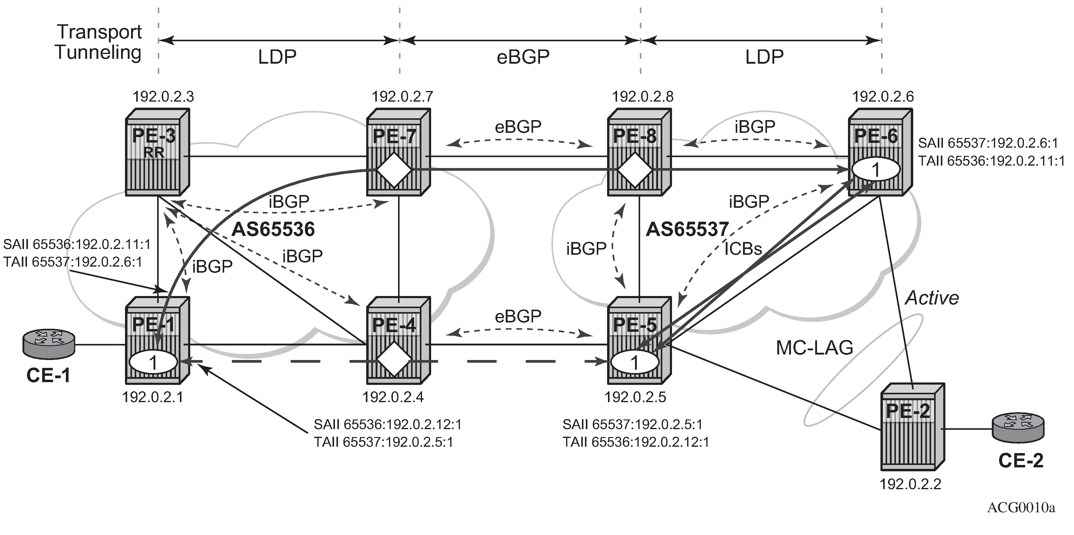
In this example, only one Epipe is configured (Epipe 1, using MS-PW BGP routing). The T-PEs are PE-1, PE-5, and PE-6; the S-PEs are PE-7, PE-8, and PE-4.
A/S pseudowire redundancy together with MC-LAG at one end will be used, as shown in Inter-AS MS-PW example topology. Inter-Chassis Backup (ICB) spoke-SDPs between PE-5 and PE-6 are required in order to forward the in-flight packets while MC-LAG and A/S pseudowire are converging, in case of network failures. Those ICBs will also be signaled following the MS-PW routing procedures.
The example topology in Inter-AS MS-PW example topology is pre-configured with the following settings:
There are two ASs (65536 and 65537) which are connected by two ASBR pairs (PE-7/PE-4 and PE-8/PE-5) running eBGP between them. These eBGP sessions will be used to exchange IPv4-labels (to set up the transport BGP-LBL tunnel, according to the RFC 3107) and MS-PW NLRIs.
Within AS65536, PE-3 is used as an RR to reflect the MS-PW routes. In AS65537, there is a full mesh of iBGP sessions to distribute the MS-PW routes.
IS-IS is used within each AS.
LDP is used as a transport MPLS signaling protocol within each AS and a BGP tunnel will be used between the ASBRs (MS-PW routing supports LDP or BGP tunnels as transport).
A redundant MC-LAG access to PE-6 and PE-5 is configured.
The next section will go through the configuration required to set up a redundant Epipe between CE-1 and CE-2, by combining A/S pseudowire in the network and MC-LAG at the access.
MS-PW using BGP routing
Epipe 1 will be configured at the end of this section, including the active and redundant pseudowires from PE-1 to PE-5/PE-6, as well as the required ICBs and SAPs at the access.
As discussed, the first step is the provisioning of the pw-routing context. Again, the spe-address must be provisioned in all T-PEs and S-PEs whereas prefixes are mandatory only on the T-PEs involved in the service. The following shows the prefixes configured on PE-1, PE-5, and PE-6. Two prefixes are needed in PE-1 in order to make sure that active and standby pseudowires follow disjoint paths.
# on PE-1:
configure
    service
        pw-routing
            spe-address 65536:192.0.2.1
            local-prefix 65536:192.0.2.11 create
                advertise-bgp route-distinguisher 65536:11 community 65535:11
            exit
            local-prefix 65536:192.0.2.12 create
                advertise-bgp route-distinguisher 65536:12 community 65535:12
            exit
# on PE-5:
configure
    service
        pw-routing
            spe-address 65537:192.0.2.5
            local-prefix 65537:192.0.2.5 create
                advertise-bgp route-distinguisher 65537:5 community 65535:5
            exit
# on PE-6:
configure
    service
        pw-routing
            spe-address 65537:192.0.2.6
            local-prefix 65537:192.0.2.6 create
                advertise-bgp route-distinguisher 65537:6 community 65535:60
            exit
0xFFFF006 and 0xFFFF007 are the values that have been assigned by IANA to the well-known communities for Long-Lived Graceful Restart (LLGR): ‟LLGR_STALE” and ‟NO_LLGR”. Therefore, on PE-6, the community value must not be 65535:6, because 65535:6 would be mapped to community ‟LLGR_STALE”. The value 65535:60 is used instead.
Once the S-PE-addresses and prefixes have been provisioned, BGP must be configured accordingly. A simple BGP export policy is used to export all the local MS-PW prefixes. The configuration on PE-1 is as follows:
# on PE-1:
configure
    router
        autonomous-system 65536
        policy-options
            begin
            policy-statement "export_ms-pw"
                entry 10
                    from
                        family ms-pw
                    exit
                    action accept
                        origin igp
                    exit
                exit
            exit
            commit
        exit
        bgp
            enable-peer-tracking
            rapid-withdrawal
            group "intra-AS"
                family ms-pw
                export "export_ms-pw"
                peer-as 65536
                neighbor 192.0.2.3
                exit
            exit
            no shutdown
        exit
    exit
The configuration on PE-6 is as follows:
# on PE-6:
configure
    router
        autonomous-system 65537
        policy-options
            begin
            policy-statement "export_ms-pw"
                entry 10
                    from
                        family ms-pw
                    exit
                    action accept
                        origin igp
                    exit
                exit
            exit
            commit
        exit
        bgp
            enable-peer-tracking
            rapid-withdrawal
            group "intra-AS"
                family ms-pw
                export "export_ms-pw"
                peer-as 65537
                neighbor 192.0.2.5
                exit
                neighbor 192.0.2.8
                exit
            exit
            no shutdown
        exit
    exit
At the ASBR, the BGP policies are more complex because the following tasks must be accomplished:
ASBR IPv4 system addresses must be exported to the peer ASBR to establish the RFC 3107 BGP tunnel between ASBRs.
BGP export policies must be used so that MS-PW NLRI exchange can be controlled and attributes like Multi Exit Discriminator (MED) toward the remote AS and/or local-preference (LP) toward the local AS can be modified.
Finally, BGP import policies must also be used to modify the MS-PW route NH because the T-LDP next signaling hop must match a peer T-LDP system address.
The prefixes 65536:192.0.2.11 and 65537:192.0.2.6 must be preferred in the PE-7/PE-8 pair whereas the prefixes 65536:192.0.2.12 and 65537:192.0.2.5 must be preferred in the PE-4/PE-5 pair, so that the PWs are established as shown in Inter-AS MS-PW example topology. The preference can be propagated by using the BGP MED; the LP is used within the AS, but not relevant to eBGP. The following CLI excerpt shows an example of how to modify MED and LP, as well as changing the NH with an import policy. The configuration on ASBR PE-4 is as follows:
*A:PE-4#
configure
    router
        autonomous-system 65536
        policy-options
            begin
            prefix-list "system"
                prefix 192.0.2.4/32 exact
            exit
            community "65535:5"
                members "65535:5"
            exit
            community "65535:11"
                members "65535:11"
            exit
            community "65535:12"
                members "65535:12"
            exit
            community "65535:60"
                members "65535:60"
            exit
            policy-statement "ASBR to ASBR"
                entry 10
                    from
                        protocol bgp
                        community "65535:12"
                        family ms-pw
                    exit
                    action accept
                        origin igp
                        metric set 50
                    exit
                exit
                entry 20
                    from
                        protocol bgp
                        community "65535:11"
                        family ms-pw
                    exit
                    action accept
                        origin igp
                        metric set 100
                    exit
                exit
            exit
            policy-statement "ASBR to region"
                entry 10
                    from
                        protocol bgp
                        community "65535:5"
                        family ms-pw
                    exit
                    action accept
                        origin igp
                        local-preference 150
                        next-hop-self
                    exit
                exit
                entry 20
                    from
                        protocol bgp
                        community "65535:60"
                        family ms-pw
                    exit
                    action accept
                        origin igp
                        next-hop-self
                    exit
                exit
            exit
            policy-statement "export_ipv4_system"
                entry 10
                    from
                        prefix-list "system"
                    exit
                    action accept
                        origin igp
                    exit
                exit
            exit
            policy-statement "import ms-pw NH change"
                entry 10
                    from
                        protocol bgp
                        family ms-pw
                    exit
                    action accept
                        next-hop 192.0.2.5
                    exit
                exit
            exit
            commit
        exit
        bgp
            enable-peer-tracking
            rapid-withdrawal
            group "inter-AS"
                family ms-pw label-ipv4
                import "import ms-pw NH change"
                export "export_ipv4_system" "ASBR to ASBR"
                local-as 65536
                peer-as 65537
                neighbor 192.168.45.2
                exit
            exit
            group "intra-AS"
                family ms-pw
                export "ASBR to region"
                peer-as 65536
                neighbor 192.0.2.3
                exit
            exit
            no shutdown
        exit
The configuration on ASBR PE-7 is as follows:
# on PE-7:
configure
    router
        autonomous-system 65536
        policy-options
            begin
            prefix-list "system"
                prefix 192.0.2.7/32 exact
            exit
            community "65535:5"
                members "65535:5"
            exit
            community "65535:11"
                members "65535:11"
            exit
            community "65535:12"
                members "65535:12"
            exit
            community "65535:60"
                members "65535:60"
            exit
            policy-statement "ASBR to ASBR"
                entry 10
                    from
                        protocol bgp
                        community "65535:11"
                        family ms-pw
                    exit
                    action accept
                        origin igp
                        metric set 50
                    exit
                exit
                entry 20
                    from
                        protocol bgp
                        community "65535:12"
                        family ms-pw
                    exit
                    action accept
                        origin igp
                        metric set 100
                    exit
                exit
            exit
            policy-statement "ASBR to region"
                entry 10
                    from
                        protocol bgp
                        community "65535:60"
                        family ms-pw
                    exit
                    action accept
                        origin igp
                        local-preference 150
                        next-hop-self
                    exit
                exit
                entry 20
                    from
                        protocol bgp
                        community "65535:5"
                        family ms-pw
                    exit
                    action accept
                        origin igp
                        next-hop-self
                    exit
                exit
            exit
            policy-statement "export_ipv4_system"
                entry 10
                    from
                        prefix-list "system"
                    exit
                    action accept
                        origin igp
                    exit
                exit
            exit
            policy-statement "import ms-pw NH change"
                entry 10
                    from
                        protocol bgp
                        family ms-pw
                    exit
                    action accept
                        next-hop 192.0.2.8
                    exit
                exit
            exit
            commit
        exit
        bgp
            enable-peer-tracking
            rapid-withdrawal
            group "inter-AS"
                family ms-pw label-ipv4
                import "import ms-pw NH change"
                export "export_ipv4_system" "ASBR to ASBR"
                local-as 65536
                peer-as 65537
                neighbor 192.168.78.2
                exit
            exit
            group "intra-AS"
                family ms-pw
                export "ASBR to region"
                peer-as 65536
                neighbor 192.0.2.3
                exit
            exit
            no shutdown
        exit
PE-5 and PE-8 have similar configurations to the ones shown. However, PE-5 is a T-PE as well as an ASBR, therefore a local MS-PW prefix must be exported as opposed to only remote prefixes (that is, some export entries for the local MS-PW routes will not contain protocol bgp in the matching criteria).
After BGP is properly configured and the updates get exchanged, the RIBs are populated and the prefixes uploaded onto the MS-PW routing table as shown for PE-1 in the following output:
*A:PE-1# show router bgp routes ms-pw
===============================================================================
 BGP Router ID:192.0.2.1        AS:65536       Local AS:65536
===============================================================================
 Legend -
 Status codes  : u - used, s - suppressed, h - history, d - decayed, * - valid
                 l - leaked, x - stale, > - best, b - backup, p - purge
 Origin codes  : i - IGP, e - EGP, ? - incomplete

===============================================================================
BGP MSPW Routes
===============================================================================
Flag  Network                 RD
      Nexthop                 AII-Type2/Preflen
      As-Path
-------------------------------------------------------------------------------
---snip---
u*>i  65537:192.0.2.5         65537:5
      192.0.2.4               65537:192.0.2.5:0/64
      65537
u*>i  65537:192.0.2.6         65537:6
      192.0.2.7               65537:192.0.2.6:0/64
      65537
-------------------------------------------------------------------------------
Routes : 4
===============================================================================
*A:PE-1# show service pw-routing route-table

===============================================================================
Service PW L2 Routing Information
===============================================================================
AII-Type2/Prefix-Len                           Next-Hop       Owner  Age
 Route-Distinguisher                            Community      Best
-------------------------------------------------------------------------------
65536:192.0.2.11:0/64                          192.0.2.1      local  00h09m19s
 0:0                                            0:0            yes
65536:192.0.2.11:0/64                          192.0.2.1      local  00h09m19s
 65536:11                                       65535:11       yes
65536:192.0.2.12:0/64                          192.0.2.1      local  00h09m19s
 0:0                                            0:0            yes
65536:192.0.2.12:0/64                          192.0.2.1      local  00h09m19s
 65536:12                                       65535:12       yes
65537:192.0.2.5:0/64                           192.0.2.4      bgp    00h02m34s
 65537:5                                        65535:5        yes
65537:192.0.2.6:0/64                           192.0.2.7      bgp    00h02m01s
 65537:6                                        65535:60       yes
-------------------------------------------------------------------------------
Entries found: 6
===============================================================================
For PE-6:
*A:PE-6# show router bgp routes ms-pw
===============================================================================
 BGP Router ID:192.0.2.6        AS:65537       Local AS:65537
===============================================================================
 Legend -
 Status codes  : u - used, s - suppressed, h - history, d - decayed, * - valid
                 l - leaked, x - stale, > - best, b - backup, p - purge
 Origin codes  : i - IGP, e - EGP, ? - incomplete

===============================================================================
BGP MSPW Routes
===============================================================================
Flag  Network                 RD
      Nexthop                 AII-Type2/Preflen
      As-Path
-------------------------------------------------------------------------------
u*>i  65536:192.0.2.11        65536:11
      192.0.2.8               65536:192.0.2.11:0/64
      65536
u*>i  65536:192.0.2.12        65536:12
      192.0.2.5               65536:192.0.2.12:0/64
      65536
u*>i  65537:192.0.2.5         65537:5
      192.0.2.5               65537:192.0.2.5:0/64
      No As-Path
-------------------------------------------------------------------------------
Routes : 3
===============================================================================
*A:PE-6# show service pw-routing route-table

===============================================================================
Service PW L2 Routing Information
===============================================================================
AII-Type2/Prefix-Len                           Next-Hop       Owner  Age
 Route-Distinguisher                            Community      Best
-------------------------------------------------------------------------------
65536:192.0.2.11:0/64                          192.0.2.8      bgp    00h02m32s
 65536:11                                       65535:11       yes
65536:192.0.2.12:0/64                          192.0.2.5      bgp    00h02m52s
 65536:12                                       65535:12       yes
65537:192.0.2.5:0/64                           192.0.2.5      bgp    00h02m52s
 65537:5                                        65535:5        yes
65537:192.0.2.6:0/64                           192.0.2.6      local  00h08m43s
 0:0                                            0:0            yes
65537:192.0.2.6:0/64                           192.0.2.6      local  00h08m43s
 65537:6                                        65535:60       yes
-------------------------------------------------------------------------------
Entries found: 5
===============================================================================
As can be seen in the preceding show commands on PE-6, the two PE-1 prefixes are learned on (PE-5 and) PE-6 through different and disjoint paths. On PE-1, the PE-5 and PE-6 prefixes are learned through two different and disjoint paths.
After configuring the PW routing context and configuring BGP, the last step is the service configuration on the three T-PEs, as follows. T-LDP sessions must have been previously and explicitly configured between the T-PEs and S-PEs (between PE-1 and PE-4/7, between PE-4 and PE-5, PE-7 and PE-8, and between PE-6 and PE-5/8).
# on PE-1:
configure
    router Base
        ldp
            targeted-session
                peer 192.0.2.4
                exit
                peer 192.0.2.7
                exit
            exit
        exit
    exit
    service
        pw-template 1 name "PW1" create
            controlword
        exit
        epipe 1 name "Epipe1" customer 1 create
            description "ms-pw epipe with bgp, inter-AS, MC-LAG redundancy"
            endpoint "CORE" create
                description "endpoint for epipe A/S PW redundancy"
            exit
            sap 1/1/4:1 create
            exit
            spoke-sdp-fec 11 fec 129 aii-type 2 create endpoint CORE
                precedence primary
                pw-template-bind 1
                saii-type2 65536:192.0.2.11:1
                taii-type2 65537:192.0.2.6:1
                no shutdown
            exit
            spoke-sdp-fec 12 fec 129 aii-type 2 create endpoint CORE
                pw-template-bind 1
                saii-type2 65536:192.0.2.12:1
                taii-type2 65537:192.0.2.5:1
                no shutdown
            exit
            no shutdown
        exit
# on PE-5:
configure
    service
        pw-template 1 name "PW1" create
            controlword
        exit
        epipe 1 name "Epipe1" customer 1 create
            description "ms-pw epipe with bgp, inter-AS, MC-LAG redundancy"
            endpoint "CORE" create
                description "endpoint for epipe A/S PW redundancy"
            exit
            endpoint "ACCESS" create
            exit
            sap lag-1:1 endpoint "ACCESS" create
            exit
            spoke-sdp-fec 11 fec 129 aii-type 2 create endpoint CORE
                pw-template-bind 1
                saii-type2 65537:192.0.2.5:1
                taii-type2 65536:192.0.2.12:1
                no shutdown
            exit
            spoke-sdp-fec 12 fec 129 aii-type 2 create endpoint CORE icb
                pw-template-bind 1
                saii-type2 65537:192.0.2.5:2
                taii-type2 65537:192.0.2.6:2
                no shutdown
            exit
            spoke-sdp-fec 13 fec 129 aii-type 2 create endpoint ACCESS icb
                pw-template-bind 1
                saii-type2 65537:192.0.2.5:3
                taii-type2 65537:192.0.2.6:3
                no shutdown
            exit
            no shutdown
        exit
# on PE-6:
configure
    service
        pw-template 1 name "PW1" create
            controlword
        exit
        epipe 1 name "Epipe1" customer 1 create
            description "ms-pw epipe with bgp, inter-AS, MC-LAG redundancy"
            endpoint "CORE" create
                description "endpoint for epipe A/S PW redundancy"
            exit
            endpoint "ACCESS" create
            exit
            sap lag-1:1 endpoint "ACCESS" create
            exit
            spoke-sdp-fec 11 fec 129 aii-type 2 create endpoint CORE
                pw-template-bind 1
                saii-type2 65537:192.0.2.6:1
                taii-type2 65536:192.0.2.11:1
                no shutdown
            exit
            spoke-sdp-fec 12 fec 129 aii-type 2 create endpoint CORE icb
                pw-template-bind 1
                saii-type2 65537:192.0.2.6:3
                taii-type2 65537:192.0.2.5:3
                no shutdown
            exit
            spoke-sdp-fec 13 fec 129 aii-type 2 create endpoint ACCESS icb
                pw-template-bind 1
                saii-type2 65537:192.0.2.6:2
                taii-type2 65537:192.0.2.5:2
                no shutdown
            exit
            no shutdown
        exit
The following show commands can be executed to check the status of the Epipe 1 and the pseudowire status signaling received:
*A:PE-1# show service id 1 base

===============================================================================
Service Basic Information
===============================================================================
Service Id        : 1                   Vpn Id            : 0
Service Type      : Epipe
---snip---

Admin State       : Up                  Oper State        : Up
---snip---

-------------------------------------------------------------------------------
Service Access & Destination Points
-------------------------------------------------------------------------------
Identifier                               Type         AdmMTU  OprMTU  Adm  Opr
-------------------------------------------------------------------------------
sap:1/1/4:1                              q-tag        1518    1518    Up   Up
sdp:32766:4294967294 SB(192.0.2.7)       MS-PW        0       9190    Up   Up
sdp:32767:4294967295 SB(192.0.2.4)       MS-PW        0       9190    Up   Up
===============================================================================
*A:PE-1# show service id 1 endpoint

===============================================================================
Service 1 endpoints
===============================================================================
Endpoint name                : CORE
Description                  : endpoint for epipe A/S PW redundancy
Creation Origin              : manual
Revert time                  : 0
Act Hold Delay               : 0
Standby Signaling Master     : false
Standby Signaling Slave      : false
Tx Active (SDP-FEC)          : 11
Tx Active Up Time            : 0d 00:00:35
Revert Time Count Down       : never
Tx Active Change Count       : 2
Last Tx Active Change        : 03/03/2021 10:49:02
-------------------------------------------------------------------------------
Members
-------------------------------------------------------------------------------
Sdp-fec: 11 Prec:0                                Oper Status: Up
Sdp-fec: 12 Prec:4                                Oper Status: Up
===============================================================================
===============================================================================
PE-5 will have the MC-LAG standby interface and as such the SAP will be operationally down and will drive the standby signaling to the remote T-PEs:
*A:PE-5# show service id 1 base

===============================================================================
Service Basic Information
===============================================================================
Service Id        : 1                   Vpn Id            : 0
Service Type      : Epipe
---snip---

Admin State       : Up                  Oper State        : Up
---snip---

-------------------------------------------------------------------------------
Service Access & Destination Points
-------------------------------------------------------------------------------
Identifier                               Type         AdmMTU  OprMTU  Adm  Opr
-------------------------------------------------------------------------------
sap:lag-1:1                              q-tag        1518    1518    Up   Down
sdp:32766:4294967293 SB(192.0.2.6)       MS-PW        0       9190    Up   Up
sdp:32766:4294967294 SB(192.0.2.6)       MS-PW        0       9190    Up   Up
sdp:32767:4294967295 SB(192.0.2.4)       MS-PW        0       9190    Up   Up
===============================================================================
*A:PE-5# show service id 1 all | match Flags
Flags              : None
Flags              : None
Flags              : None
Flags              : PortOperDown StandByForMcProtocol
The following commands are useful on the S-PEs in order to find the PWs automatically created as well as the SDPs automatically used for those PWs.
*A:PE-7# show service sdp-using

===============================================================================
SDP Using
===============================================================================
SvcId      SdpId              Type   Far End              Opr   I.Label E.Label
                                                          State
-------------------------------------------------------------------------------
2147483647 32766:4294967294   MS-PW  192.0.2.1            Up    524280  524282
2147483647 32767:4294967295   MS-PW  192.0.2.8            Up    524281  524281
-------------------------------------------------------------------------------
Number of SDPs : 2
-------------------------------------------------------------------------------
===============================================================================
As it can be seen in the preceding output, two PWs (type MS-PW) have been automatically created over two also automatically created SDPs: 32766 and 32767. SDP 32766 is built over an LDP tunnel whereas SDP 32767 runs over a BGP tunnel.
*A:PE-7# show router tunnel-table

===============================================================================
IPv4 Tunnel Table (Router: Base)
===============================================================================
Destination           Owner     Encap TunnelId  Pref   Nexthop        Metric
   Color
-------------------------------------------------------------------------------
192.0.2.1/32          sdp       MPLS  32766     5      192.0.2.1      0
192.0.2.1/32          ldp       MPLS  65539     9      192.168.37.1   20
192.0.2.3/32          ldp       MPLS  65538     9      192.168.37.1   10
192.0.2.4/32          ldp       MPLS  65537     9      192.168.47.1   10
192.0.2.8/32          sdp       MPLS  32767     5      192.0.2.8      0
192.0.2.8/32          bgp       MPLS  262145    12     192.168.78.2   1000
-------------------------------------------------------------------------------
Flags: B = BGP or MPLS backup hop available
       L = Loop-Free Alternate (LFA) hop available
       E = Inactive best-external BGP route
       k = RIB-API or Forwarding Policy backup hop
===============================================================================
*A:PE-7# show service sdp 32766 detail | match "Active LSP"
Mixed LSP Mode       : Enabled               Active LSP Type    : LDP
*A:PE-7# show service sdp 32767 detail | match "Active LSP"
Mixed LSP Mode       : Enabled               Active LSP Type    : BGP
In addition to all of the recommended show commands, vccv-ping and vccv-trace are two extremely useful commands in this environment. vccv-trace can even help to trace the traffic going through the ICBs under failure situations.
Conclusion
Service Providers are always seeking highly scalable VLL services that can be deployed with the lowest operational cost. The SR OS supports MS-PW routing according to the draft-ietf-pwe3-dynamic-ms-pw. MS-PW routing allows the Service Provider to deploy Epipe services without having to provision services in the core of the network. In other words, MS-PW enables end-point provisioning in highly scalable seamless MPLS networks, through the use of BGP. Alternatively, static MS-PW routes or explicit paths can also be used.
The examples used in this chapter illustrate the configuration of MS-PW routing in intra-AS and inter-AS scenarios. Show and OAM commands have also been suggested so that the operator can verify and troubleshoot the MS-PW routing paths and procedures.