Layer 2 Multicast Optimization for EVPN-VXLAN — Assisted Replication
This chapter provides information about Layer 2 Multicast Optimization for EVPN-VXLAN — Assisted Replication.
Topics in this chapter include:
Applicability
This chapter was initially written for SR OS Release 14.0.R4, but the CLI in the current edition is based on SR OS Release 23.3.R3. Layer 2 multicast optimization for EVPN-VXLAN - Assisted Replication (AR) is supported in SR OS Release 14.0.R4, and later.
Overview
Typically, EVPN-VXLAN can use either Ingress Replication (IR) or Protocol Independent Multicast (PIM) for Broadcast, Unknown unicast, and Multicast (BUM) traffic (although SR OS does not support PIM along with EVPN-VXLAN). PIM requires keeping multicast state awareness per subnet per tenant in the core routers, which may not scale. Not all core routers support PIM.
IR inefficiency is usually tolerable in EVPN networks for broadcast and unknown unicast traffic; however, it is not tolerable for multicast traffic:
Broadcast traffic can be reduced by the proxy-ARP and proxy-ND capabilities supported by EVPN.
Unknown unicast traffic is greatly reduced in virtualized Data Center (DC) networks where all MAC and IP addresses are learned in the control or management planes. In such cases, unknown MAC addresses are always outside the DC. An unknown-mac-route can be enabled to ensure that the unknown unicast traffic is sent only to the DC gateway, which minimizes flooding within the DC.
Multicast traffic may be an issue for the hypervisors holding the multicast sources, because the hypervisors need to replicate the multicast traffic to the remote VXLAN Tunnel Endpoints (VTEPs). The multicast replication at the hypervisors is a software process and the throughput can be heavily impacted. This is also true when VPLS services are used in the Virtual Service Router (VSR) and many replicas must be done from the VSR. Using a dedicated service node to replicate the multicast traffic on behalf of the hypervisors can help, but the replication capabilities of such service nodes are limited too.
SR OS supports the Assisted Replication (AR) feature for IPv4 VXLAN tunnels (both replicator and leaf functions) in compliance with the non-selective mode described in draft-ietf-bess-evpn-optimized-ir. AR is a Layer 2 multicast optimization feature that helps software-based PEs and Network Virtualization Edge (NVE) devices with low-performance replication capabilities to deliver Broadcast and Multicast (BM) Layer 2 traffic to remote VTEPs in the VPLS.
SR OS nodes support the AR-Replicator (AR-R) and AR-Leaf (AR-L) functions, although not simultaneously on the same service. Nodes configured as AR-L select an AR-R within a service and send all BM packets to this AR-R. AR-Rs replicate traffic to all the VTEPs in the VPLS on behalf of the AR-Ls, so BM traffic is delivered to all VPLS participants without any packet loss caused by performance issues. Unknown unicast packets follow the same path as known unicast packets to avoid packet reordering. Therefore, no AR-R is used for unknown unicast traffic.
When multiple AR-Rs exist in a service, the AR-L performs per-service load-balancing of the BM traffic. The AR-L lists the candidate AR-Rs, ordered by IP address and VXLAN Network Identifier (VNI); candidate 0 having the lowest IP address and VNI. The replicator is selected using a modulo function of the service ID and the number of candidate AR-Rs. For example, assume that VPLS 1 has two candidate AR-Rs: because 1 modulo 2 equals 1, the second AR-R in the list is selected. In case of failure, a new AR-R is selected. If there are no more AR-Rs, the system falls back to IR.
PMSI Tunnel Attribute - Flags shows an EVPN route-type 3, an Inclusive Multicast Ethernet Tag (IMET) route containing a PMSI tunnel attribute with a flags octet. Flag L was already defined in RFC 6514. Draft-ietf-bess-evpn-optimized-ir defines additional flags: type, BM, and U. The BM and U flags are used for Pruned Flood Lists (PFL) signaling and they are not supported.
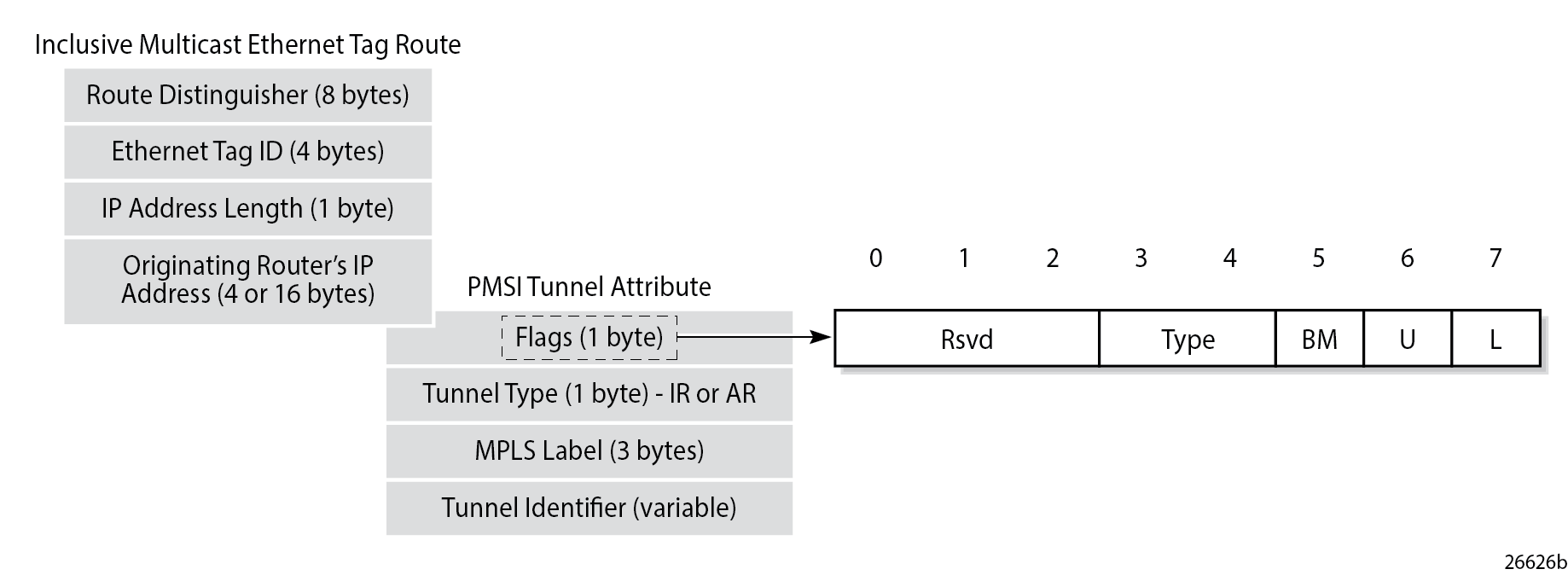
The type field has two bits that define the AR role of the advertising router, as follows:
Type 00 = Regular Network Virtualization Edge (RNVE) - indicates that AR is not supported and IR is applied instead (for backward compatibility)
Type 01= AR-R
Type 10 = AR-L
Type 11 = reserved
The tunnel type in the PMSI tunnel attribute can be configured with the following options for IR and AR:
Tunnel type 0x06 = (non-optimized) IR, sent by AR-R and AR-L if ingress-repl-inc-mcast-advertisement is enabled, which is the default option
Tunnel type 0x0A = type AR, originated by AR-R
For regular IR routes, the originating router's IP address equals the system IP address. The MPLS label and tunnel identifier must be used as described in RFC 7432. The tunnel identifier is set to a routable address of the PE.
For AR routes, the originating router's IP address and the tunnel identifier are both set to the AR IP address (AR-IP) configured in the service system vxlan context. The AR-IP must be previously defined as a loopback interface address in the base router and must be different from the IR IP address (IR-IP).
If the AR-IP loopback interface is down, the router does not withdraw the AR route. However, the remote AR-Ls is not able to resolve the AR route's BGP next-hop if the AR-IP is no longer propagated in the IGP.
EVPN Assisted Replication for VXLAN shows the example topology with the multicast source connected to a hypervisor PE-3 that acts as AR-L, which sends an IR route containing the system address of PE-3. The AR-R PE-1 sends an AR route that uses AR-IPs instead of IR-IPs; for example, PE-1 has AR-IP 1.1.1.1 and IR-IP 192.0.2.1.
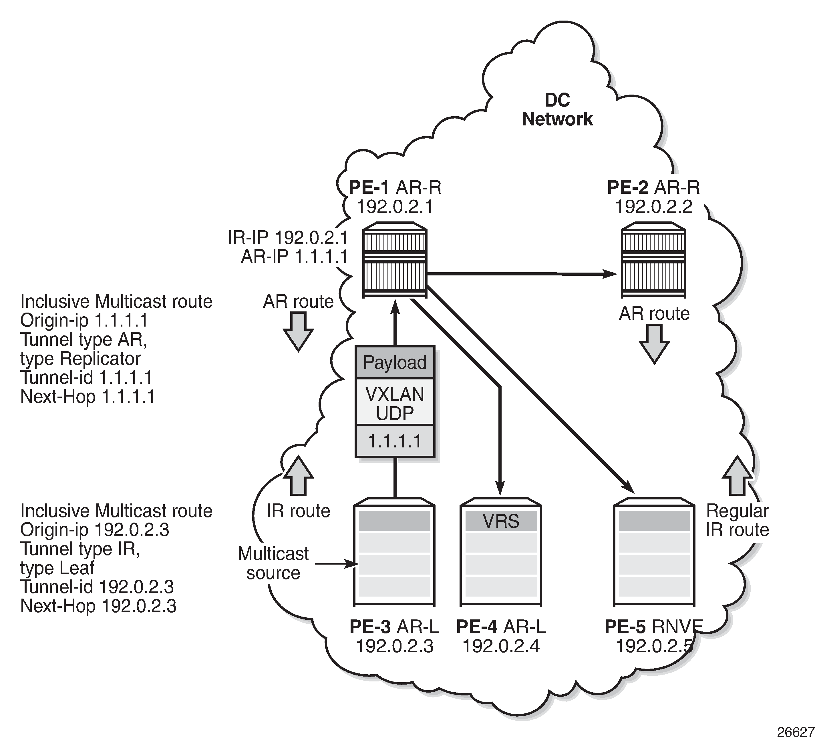
Hypervisor PE-3 sends the BM traffic to the AR-R, which replicates it to all the VTEPs in the VPLS, except to PE-3.
Inclusive multicast route information sent by different AR roles shows the inclusive multicast route information sent by each role in an AR-capable service.
AR role |
function |
inclusive multicast route advertised |
|---|---|---|
AR-R |
assists AR-Ls |
IR inclusive multicast route (tunnel = 0x06 = IR, IR-IP, type = 0 = none) AR inclusive multicast route (tunnel = 0x0A = AR, AR-IP, type = 1 = AR-R) |
AR-L |
sends BM only to AR-R |
IR inclusive multicast route (tunnel = 0x06 = IR, IR- IP, type = 2 = AR-L) |
RNVE |
non-AR support |
IR inclusive multicast route (tunnel = 0x06 = IR, IR- IP, type = 0 = none) |
Unicast traffic (known or unknown) is processed as normal. For BM traffic, the AR-R uses AR or IR based on the IP destination address (DA):
If IP DA equals the AR-IP, the AR-R replicates to the VTEPs in the VXLAN service, except for the VTEP over which the BM traffic was received.
If IP DA equals the IR-IP, normal IR forwarding is done.
Non-optimized-IR nodes are unaware of the PMSI tunnel attribute flag definition with the additional flags for AR, so they ignore the information in the flags field.
The draft-ietf-bess-evpn-optimized-ir describes the following three types of IR optimizations:
Non-selective AR - the chosen AR-R replicates the BM traffic to all NVEs in the Ethernet VPN Instance (EVI) except for the source NVE.
Selective AR - AR-Rs replicate BM traffic to only their AR-L set and the rest of the AR-Rs. Selective AR allows a "multi-stage" AR replication, as opposed to a "single-stage" AR replication.
Pruned Flood Lists - AR-Ls can signal PFL flags to be pruned from the flood lists for BM or for unknown unicast traffic. PFL may be used in combination with AR.
This chapter only describes non-selective AR.
Configure AR-R and AR-L
The AR-IP is configured on the AR-R, as follows:
*A:PE-1# configure service system vxlan assisted-replication-ip ?
  - assisted-replication-ip <ip-address>
  - no assisted-replication-ip

 <ip-address>         : a.b.c.d
The AR-IP is the IPv4 address of a loopback interface in the base router instance. When attempting to configure an AR-IP and the loopback address does not exist, the following error message is raised:
*A:PE-1# configure service system vxlan assisted-replication-ip 1.1.1.1
MINOR: SVCMGR #8110 Cannot change assisted-replicated address
 - loopback interface with address does not exist
The AR types replicator and leaf are configured in a VPLS with the following command:
*A:PE-1# configure service vpls 10 vxlan instance 1 vni 1 assisted-replication ?
  - assisted-replication {replicator|leaf} [replicator-activation-time <seconds>]
  - no assisted-replication

 <replicator|leaf>    : replicator|leaf
 <seconds>            : [1..255]
When attempting to configure an AR-R before the AR-IP is set, the following error is raised:
*A:PE-1# configure service vpls 10 name "VPLS 10" customer 1 create vxlan instance 1 vni 1 create assisted-replication replicator
MINOR: SVCMGR #8111 Cannot change assisted-replicated role
 - assisted replicator ip not set
The AR type (AR-R or AR-L) cannot be changed while being used by any BGP-EVPN service. The following error is raised in such a case:
*A:PE-1# configure service vpls 10 vxlan instance 1 vni 1 assisted-replication leaf
MINOR: SVCMGR #8111 Cannot change assisted-replicated role - Evpn not shut
The assisted-replication-time can only be configured on leaf nodes. The following error is raised after an attempt to configure the assisted-replication-time on an AR-R:
*A:PE-1# configure service vpls 10 vxlan instance 1 vni 1 assisted-replication replicator replicator-activation-time 5
MINOR: SVCMGR #8112 Cannot change replicator activation time - valid only on leaf
The replicator-activation-time can optionally be activated, and works as follows. When the router creates an AR-R destination for the first time, the assisted-replication-timer must expire before this AR-R destination is eligible as candidate AR-R to forward BM traffic. Upon timer expiration, the router runs the AR-R selection (service ID modulo the number of AR-Rs provides the selected AR-R in the ordered list of candidate AR-Rs). The AR-R EVPN destination is created as "BM" and the destinations to the remaining nodes is shown as "U".
The replicator-activation-time allows the AR-R some time to program the leaf VTEPs in the following cases:
Configuration of a new AR-R
AR-R rebooting
AR-R going operationally down and up again
If the timer is zero (default value), the AR-R may receive packets from a VTEP that has not been programmed yet, in which case the AR-R drops the packets.
With the AR-Rs and AR-Ls configured, IMET AR routes can be exchanged. IR can be enabled or disabled independently of the AR configuration. The following command is required to enable IR inclusive multicast routes, and is enabled by default:
*A:PE-1# configure service vpls 10 bgp-evpn ingress-repl-inc-mcast-advertisement
BGP-EVPN routes
By default, IR is enabled in BGP-EVPN. The following IMET IR route is sent from PE-5 (RNVE) to Route Reflector (RR) PE-1. The flags in the PMSI Tunnel Attribute (PTA) indicate that regular IR is used to forward BUM traffic (tunnel type: 0x06). The AR type is "None", because AR is disabled on PE-5. The IR-IP 192.0.2.5 is used as next-hop, originator IP address, and tunnel endpoint. The MPLS label corresponds to the VNI.
*A:PE-5# show debug
debug
    router "Base"
        bgp
            update
On PE-5:
12 2023/07/07 09:56:26.369 UTC MINOR: DEBUG #2001 Base Peer 1: 192.0.2.1
"Peer 1: 192.0.2.1: UPDATE
Peer 1: 192.0.2.1 - Send BGP UPDATE:
    Withdrawn Length = 0
    Total Path Attr Length = 77
    Flag: 0x90 Type: 14 Len: 28 Multiprotocol Reachable NLRI:
        Address Family EVPN
        NextHop len 4 NextHop 192.0.2.5
        Type: EVPN-INCL-MCAST Len: 17 RD: 192.0.2.5:1, tag: 0, orig_addr len: 32, orig_addr: 192.0.2.5
    Flag: 0x40 Type: 1 Len: 1 Origin: 0
    Flag: 0x40 Type: 2 Len: 0 AS Path:
    Flag: 0x40 Type: 5 Len: 4 Local Preference: 100
    Flag: 0xc0 Type: 16 Len: 16 Extended Community:
        target:64500:1
        bgp-tunnel-encap:VXLAN
    Flag: 0xc0 Type: 22 Len: 9 PMSI:
        Tunnel-type Ingress Replication (6)
        Flags: (0x0)[Type: None BM: 0 U: 0 Leaf: not required]
        MPLS Label 1
        Tunnel-Endpoint 192.0.2.5
"
A similar IMET IR route is sent from AR-L PE-3 toward RR PE-1, as follows. The difference is that the flags indicate that PE-3 is configured as an AR-L for the VPLS. The IR-IP 192.0.2.3 is used as next-hop, originator address, and tunnel endpoint.
On PE-3:
8 2023/07/07 09:55:54.883 UTC MINOR: DEBUG #2001 Base Peer 1: 192.0.2.1
"Peer 1: 192.0.2.1: UPDATE
Peer 1: 192.0.2.1 - Send BGP UPDATE:
    Withdrawn Length = 0
    Total Path Attr Length = 77
    Flag: 0x90 Type: 14 Len: 28 Multiprotocol Reachable NLRI:
        Address Family EVPN
        NextHop len 4 NextHop 192.0.2.3
        Type: EVPN-INCL-MCAST Len: 17 RD: 192.0.2.3:1, tag: 0, orig_addr len: 32, orig_addr: 192.0.2.3
    Flag: 0x40 Type: 1 Len: 1 Origin: 0
    Flag: 0x40 Type: 2 Len: 0 AS Path:
    Flag: 0x40 Type: 5 Len: 4 Local Preference: 100
    Flag: 0xc0 Type: 16 Len: 16 Extended Community:
        target:64500:1
        bgp-tunnel-encap:VXLAN
    Flag: 0xc0 Type: 22 Len: 9 PMSI:
        Tunnel-type Ingress Replication (6)
        Flags: (0x10)[Type: AR Leaf BM: 0 U: 0 Leaf: not required]
        MPLS Label 1
        Tunnel-Endpoint 192.0.2.3
"
The IMET IR routes contain the system IP addresses of the nodes, not the AR-IPs.
The following AR route is advertised from AR-R PE-1. The tunnel type is AR and the flags indicate that PE-1 is configured as AR-R. The AR-IP 1.1.1.1 is the next-hop address, the originator address, and the tunnel endpoint.
On PE-1:
4 2023/07/07 09:55:29.613 UTC MINOR: DEBUG #2001 Base Peer 1: 192.0.2.4
"Peer 1: 192.0.2.4: UPDATE
Peer 1: 192.0.2.4 - Send BGP UPDATE:
    Withdrawn Length = 0
    Total Path Attr Length = 77
    Flag: 0x90 Type: 14 Len: 28 Multiprotocol Reachable NLRI:
        Address Family EVPN
        NextHop len 4 NextHop 1.1.1.1
        Type: EVPN-INCL-MCAST Len: 17 RD: 192.0.2.1:1, tag: 0, orig_addr len: 32, orig_addr: 1.1.1.1
    Flag: 0x40 Type: 1 Len: 1 Origin: 0
    Flag: 0x40 Type: 2 Len: 0 AS Path:
    Flag: 0x40 Type: 5 Len: 4 Local Preference: 100
    Flag: 0xc0 Type: 16 Len: 16 Extended Community:
        target:64500:1
        bgp-tunnel-encap:VXLAN
    Flag: 0xc0 Type: 22 Len: 9 PMSI:
        Tunnel-type Assisted Replication (10)
        Flags: (0x8)[Type: AR Replicator BM: 0 U: 0 Leaf: not required]
        MPLS Label 1
        Tunnel-Endpoint 1.1.1.1
"
Besides IMET AR routes, PE-1 may also advertise IMET IR routes to the other nodes using IR-IP 192.0.2.1 (system IP address). By default, BGP-EVPN has IR enabled. For example, the following IMET IR route is advertised to PE-4:
On PE-1:
3 2023/07/07 09:55:29.613 UTC MINOR: DEBUG #2001 Base Peer 1: 192.0.2.4
"Peer 1: 192.0.2.4: UPDATE
Peer 1: 192.0.2.4 - Send BGP UPDATE:
    Withdrawn Length = 0
    Total Path Attr Length = 77
    Flag: 0x90 Type: 14 Len: 28 Multiprotocol Reachable NLRI:
        Address Family EVPN
        NextHop len 4 NextHop 192.0.2.1
        Type: EVPN-INCL-MCAST Len: 17 RD: 192.0.2.1:1, tag: 0, orig_addr len: 32, orig_addr: 192.0.2.1
    Flag: 0x40 Type: 1 Len: 1 Origin: 0
    Flag: 0x40 Type: 2 Len: 0 AS Path:
    Flag: 0x40 Type: 5 Len: 4 Local Preference: 100
    Flag: 0xc0 Type: 16 Len: 16 Extended Community:
        target:64500:1
        bgp-tunnel-encap:VXLAN
    Flag: 0xc0 Type: 22 Len: 9 PMSI:
        Tunnel-type Ingress Replication (6)
        Flags: (0x0)[Type: None BM: 0 U: 0 Leaf: not required]
        MPLS Label 1
        Tunnel-Endpoint 192.0.2.1
"
The following IMET routes have been received by PE-4:
*A:PE-4# show router bgp routes evpn incl-mcast
===============================================================================
 BGP Router ID:192.0.2.4        AS:64500       Local AS:64500
===============================================================================
 Legend -
 Status codes  : u - used, s - suppressed, h - history, d - decayed, * - valid
                 l - leaked, x - stale, > - best, b - backup, p - purge
 Origin codes  : i - IGP, e - EGP, ? - incomplete

===============================================================================
BGP EVPN Inclusive-Mcast Routes
===============================================================================
Flag  Route Dist.         OrigAddr
      Tag                 NextHop
-------------------------------------------------------------------------------
u*>i  192.0.2.1:1         1.1.1.1
      0                   1.1.1.1

u*>i  192.0.2.1:1         192.0.2.1
      0                   192.0.2.1

u*>i  192.0.2.2:1         2.2.2.2
      0                   2.2.2.2

u*>i  192.0.2.2:1         192.0.2.2
      0                   192.0.2.2

u*>i  192.0.2.3:1         192.0.2.3
      0                   192.0.2.3

u*>i  192.0.2.5:1         192.0.2.5
      0                   192.0.2.5

-------------------------------------------------------------------------------
Routes : 6
===============================================================================
Configuration
Example topology shows the example topology with PE-1 and PE-2 as AR-R nodes, PE-3 and PE-4 as AR-L nodes, and PE-5 as RNVE node. The multicast source is connected to PE-3, which is a low-performance node. PE-1 acts as an RR for all nodes.
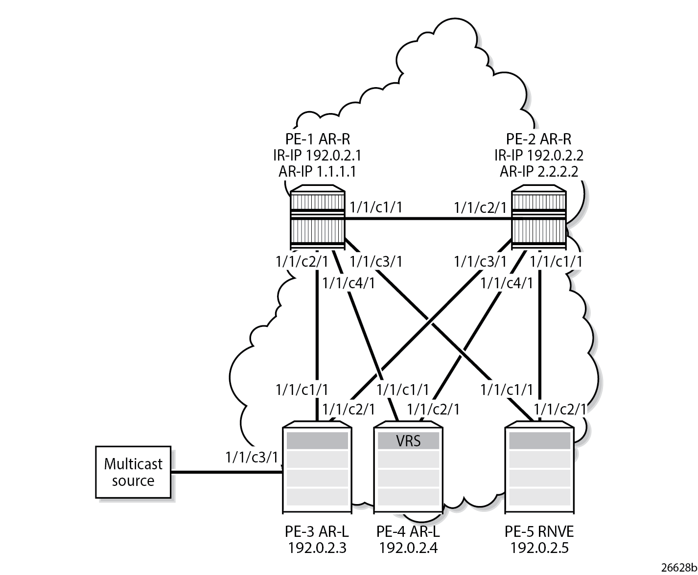
The initial configuration on the nodes includes:
Cards, MDAs, ports
Router interfaces between the nodes
IS-IS as IGP (alternatively, OSPF can be used)
BGP is configured for address family EVPN with RR PE-1. The BGP configuration on PE-1 is as follows:
On PE-1:
configure
    router
        autonomous-system 64500
        bgp
            vpn-apply-import
            vpn-apply-export
            rapid-withdrawal
            split-horizon
            rapid-update evpn
            group "DC"
                family evpn
                cluster 192.0.2.1
                peer-as 64500
                neighbor 192.0.2.2
                exit
                neighbor 192.0.2.3
                exit
                neighbor 192.0.2.4
                exit
                neighbor 192.0.2.5
                exit
            exit
        exit
The BGP configuration on the other nodes is as follows:
On the other PEs:
configure
    router
        autonomous-system 64500
        bgp
            vpn-apply-import
            vpn-apply-export
            rapid-withdrawal
            split-horizon
            rapid-update evpn
            group "DC"
                family evpn
                peer-as 64500
                neighbor 192.0.2.1
                exit
            exit
        exit
VPLS 10 is configured on all nodes. PE-1 is configured as AR-R with AR-IP 1.1.1.1, which must be configured as loopback IPv4 address in the base router and as AR-IP that can be shared between services. When attempting to configure an AR-IP with an IP address that does not exist in the base router, the following error is raised:
*A:PE-1# configure service system vxlan assisted-replication-ip 1.1.1.1
MINOR: SVCMGR #8110 Cannot change assisted-replicated address
 - loopback interface with address does not exist
First, a loopback interface is configured in the base router. The IP address needs to be routable and, in this example, an export policy exporting this IP address is configured in IS-IS. Alternatively, a static route can be configured or an additional IS-IS passive interface can be configured for the loopback interface. The IP address is then configured as AR-IP in the service system vxlan context. PE-1 is configured as AR-R for VPLS 10, as follows:
On PE-1:
configure
    router
        interface "AR-IP"
            address 1.1.1.1/32
            loopback
        exit
        policy-options
            begin
            prefix-list "AR-IP"
                prefix 1.1.1.1/32 exact
            exit
            policy-statement "export_AR-IP"
                entry 10
                    from
                        prefix-list "AR-IP"
                    exit
                    action accept
                    exit
                exit
            exit
            commit
        exit
        isis
            export "export_AR-IP"
        exit
    exit
    service
        system
            vxlan
                assisted-replication-ip 1.1.1.1
            exit
        exit
        vpls 10 name "VPLS 10" customer 1 create
            vxlan instance 1 vni 1 create
                assisted-replication replicator
            exit
            bgp
            exit
            bgp-evpn
                evi 1
                vxlan
                    no shutdown
                exit
            exit
            no shutdown
        exit
    exit
The configuration is similar on PE-2, but with AR-IP 2.2.2.2 instead of 1.1.1.1.
PE-3 and PE-4 are configured as AR-L nodes for VPLS 10. No AR-IP needs to be configured. The configuration of VPLS 10 on PE-3 is as follows:
On PE-3:
configure
    service
        vpls 10 name "VPLS 10" customer 1 create
            vxlan instance 1 vni 1 create
                assisted-replication leaf
            exit
            bgp
            exit
            bgp-evpn
                evi 1
                vxlan bgp 1 vxlan-instance 1
                    no shutdown
                exit
            exit
            sap 1/1/c3/1 create    # sap for ingress traffic from STC
            exit
            sap 1/2/c1/1:1 create    # sap for egress traffic to VPLS 10
            exit
            no shutdown
Multicast traffic enters SAP 1/1/c3/1, whereas receiving hosts can be connected to other SAPs, such as SAP 1/2/c1/1:1. The configuration of VPLS 10 on PE-4 is similar, but no multicast source is connected. When a node is configured as AR-L, optionally the replicator-activation-time can be configured to define the waiting time before the leaf can begin sending multicast traffic to a new replicator or a replicator that was rebooted. The default is zero seconds, in which case the AR-L starts sending packets to the AR-R without delay. Nokia recommends configuring a replicator-activation-time value different from zero.
*A:PE-3# configure service vpls 10 vxlan instance 1 vni 1 assisted-replication leaf ?
  - assisted-replication {replicator|leaf} [replicator-activation-time <seconds>]
  - no assisted-replication

 <replicator|leaf>    : replicator|leaf
 <seconds>            : [1..255]
PE-5 is configured as an RNVE node for VPLS 10, as follows:
On PE-5:
configure
    service
        vpls 10 name "VPLS 10" customer 1 create
            vxlan instance 1 vni 1 create
            exit
            bgp
            exit
            bgp-evpn
                evi 1
                vxlan bgp 1 vxlan-instance 1
                    no shutdown
                exit
            exit
            sap 1/2/c1/1:1 create    # sap for egress traffic to VPLS 10
            exit
            no shutdown
BGP-EVPN IMET routes are exchanged between the nodes. The following IMET routes are used on AR-L PE-3, with two routes from each AR-R: one IR route with BGP next-hop 192.0.2.x and one AR route with BGP next-hop x.x.x.x (with x equal to 1 or 2).
*A:PE-3# show router bgp routes evpn incl-mcast
===============================================================================
 BGP Router ID:192.0.2.3        AS:64500       Local AS:64500
===============================================================================
 Legend -
 Status codes  : u - used, s - suppressed, h - history, d - decayed, * - valid
                 l - leaked, x - stale, > - best, b - backup, p - purge
 Origin codes  : i - IGP, e - EGP, ? - incomplete

===============================================================================
BGP EVPN Inclusive-Mcast Routes
===============================================================================
Flag  Route Dist.         OrigAddr
      Tag                 NextHop
-------------------------------------------------------------------------------
u*>i  192.0.2.1:1         1.1.1.1
      0                   1.1.1.1

u*>i  192.0.2.1:1         192.0.2.1
      0                   192.0.2.1

u*>i  192.0.2.2:1         2.2.2.2
      0                   2.2.2.2

u*>i  192.0.2.2:1         192.0.2.2
      0                   192.0.2.2

u*>i  192.0.2.4:1         192.0.2.4
      0                   192.0.2.4

u*>i  192.0.2.5:1         192.0.2.5
      0                   192.0.2.5

-------------------------------------------------------------------------------
Routes : 6
===============================================================================
When the AR-R has no local attachment circuits, such as SAPs or SDP-bindings, it should not generate regular IR routes. This can be controlled by disabling ingress-repl-inc-mcast-advertisement on PE-1 and PE-2, as follows:
On PE-1 and PE-2:
configure
    service
        vpls 10
            bgp-evpn
                vxlan bgp 1 vxlan-instance 1 shutdown
                no ingress-repl-inc-mcast-advertisement
                vxlan bgp 1 vxlan-instance 1 no shutdown
When IR is disabled on the AR-Rs, no IR routes are sent to the other nodes and PE-3 only sees the AR routes from PE-1 and PE-2, as follows:
*A:PE-3# show router bgp routes evpn incl-mcast
===============================================================================
 BGP Router ID:192.0.2.3        AS:64500       Local AS:64500
===============================================================================
 Legend -
 Status codes  : u - used, s - suppressed, h - history, d - decayed, * - valid
                 l - leaked, x - stale, > - best, b - backup, p - purge
 Origin codes  : i - IGP, e - EGP, ? - incomplete

===============================================================================
BGP EVPN Inclusive-Mcast Routes
===============================================================================
Flag  Route Dist.         OrigAddr
      Tag                 NextHop
-------------------------------------------------------------------------------
u*>i  192.0.2.1:1         1.1.1.1
      0                   1.1.1.1

u*>i  192.0.2.2:1         2.2.2.2
      0                   2.2.2.2

u*>i  192.0.2.4:1         192.0.2.4
      0                   192.0.2.4

u*>i  192.0.2.5:1         192.0.2.5
      0                   192.0.2.5

-------------------------------------------------------------------------------
Routes : 4
===============================================================================
The detailed information about the AR route sent by AR-R PE-1 can be shown with the following command. The AR tunnel has endpoint 1.1.1.1.
*A:PE-3# show router bgp routes evpn incl-mcast rd 192.0.2.1:1 hunt
===============================================================================
 BGP Router ID:192.0.2.3        AS:64500       Local AS:64500
===============================================================================
 Legend -
 Status codes  : u - used, s - suppressed, h - history, d - decayed, * - valid
                 l - leaked, x - stale, > - best, b - backup, p - purge
 Origin codes  : i - IGP, e - EGP, ? - incomplete

===============================================================================
BGP EVPN Inclusive-Mcast Routes
===============================================================================
-------------------------------------------------------------------------------
RIB In Entries
-------------------------------------------------------------------------------
Network        : n/a
Nexthop        : 1.1.1.1
Path Id        : None
From           : 192.0.2.1
---snip---
Community      : target:64500:1 bgp-tunnel-encap:VXLAN
Cluster        : No Cluster Members
Originator Id  : None                   Peer Router Id : 192.0.2.1
Flags          : Used Valid Best IGP
Route Source   : Internal
AS-Path        : No As-Path
EVPN type      : INCL-MCAST
Tag            : 0
Originator IP  : 1.1.1.1
Route Dist.    : 192.0.2.1:1
Route Tag      : 0
---snip---
-------------------------------------------------------------------------------
PMSI Tunnel Attributes :
Tunnel-type    : Assisted Replication
Flags          : Type: AR-Replicator(1) BM: 0 U: 0 Leaf: not required
MPLS Label     : VNI 1
Tunnel-Endpoint: 1.1.1.1
-------------------------------------------------------------------------------

-------------------------------------------------------------------------------
RIB Out Entries
-------------------------------------------------------------------------------
-------------------------------------------------------------------------------
Routes : 1
===============================================================================
The following command shows the VXLAN destinations for VPLS 10 on PE-3:
*A:PE-3# show service id 10 vxlan destinations

===============================================================================
Egress VTEP, VNI (Instance 1)
===============================================================================
VTEP Address                                        Egress VNI Oper  Mcast Num
                                                               State       MACs
-------------------------------------------------------------------------------
1.1.1.1                                             1          Up    BM    0
2.2.2.2                                             1          Up    -     0
192.0.2.4                                           1          Up    U     1
192.0.2.5                                           1          Up    U     1
-------------------------------------------------------------------------------
Number of Egress VTEP, VNI : 4
-------------------------------------------------------------------------------
---snip---
===============================================================================
PE-3 is configured as AR-L and no replicator-activation-time is defined (default). Four egress VTEPs are listed: the system IP addresses are used for IR routes and the AR-IPs are used for AR routes. All BM traffic is forwarded to AR-IP 1.1.1.1 on PE-1. The AR-R in use is selected by the modulo operation on the service ID (10). In this example, two AR-Rs are available, and the service ID modulo 2 equals zero: 10 mod 2 = 0. This is the lowest possible outcome, so the first AR-R in the ordered candidate list is used. The AR-Rs are ordered by IP and VNI, with candidate 0 the lowest IP and VNI.
*A:PE-3# show service id 10 vxlan assisted-replication replicator

===============================================================================
Vxlan AR Replicator Candidates
===============================================================================
Inst  VTEP Address           Egr VNI  In Use  In Candidate List Pending Time
-------------------------------------------------------------------------------
1     1.1.1.1                1        yes     yes               0
1     2.2.2.2                1        no      yes               0
-------------------------------------------------------------------------------
Number of entries : 2
-------------------------------------------------------------------------------
===============================================================================
Within a service, no load-sharing is done between the AR-Rs. However, different AR-Rs can be used for different services.
If PE-3 were configured as AR-L in VPLS 11, the calculation would be as follows: 11 mod 2 = 1; therefore, the second AR-R in the list would be selected.
When three AR-Rs were available for VPLS 11, the calculation would be: 11 mod 3 = 2, so the third AR-R in the list would be used.
In case different VNIs are configured for the AR-Rs, the lowest IP address is always higher in the list, even when the VNI is higher. This can be shown when the VPLS VXLAN configuration on PE-1 is modified with VNI 99 instead of VNI 1, as follows:
On PE-1:
configure service vpls 10 bgp-evpn vxlan bgp 1 vxlan-instance 1 shutdown
configure service vpls 10 bgp-evpn no vxlan
configure service vpls 10 no vxlan instance 1 vni 1
configure service vpls 10 vxlan instance 1 vni 99 create assisted-replication replicator
configure service vpls 10 bgp-evpn vxlan bgp 1 vxlan-instance 1 no shutdown
The list of AR-Rs on PE-3 shows that the first entry is the VTEP with the lowest IP address (1.1.1.1), even though the VNI 99 is higher than 1:
*A:PE-3# show service id 10 vxlan assisted-replication replicator

===============================================================================
Vxlan AR Replicator Candidates
===============================================================================
Inst  VTEP Address           Egr VNI  In Use  In Candidate List Pending Time
-------------------------------------------------------------------------------
1     1.1.1.1                99       yes     yes               0
1     2.2.2.2                1        no      yes               0
-------------------------------------------------------------------------------
Number of entries : 2
-------------------------------------------------------------------------------
===============================================================================
If the AR-IP loopback interface is down, BGP does not withdraw the AR route. When the route to the AR-IP is signaled using IGP, the route is removed from the routing table and the AR-L selects another AR-R. However, when a static route is defined for the AR-IP, a black-hole exists when the AR-IP interface is down.
PE-5 is configured as an RNVE node that signals regular IMET IR routes and is unaware of the AR-R and AR-L roles in the EVI. RNVE nodes ignore IMET AR routes. In the example, only PE-3, PE-4, and PE-5 send IMET IR updates, so the list of VTEP addresses on PE-5 only contains PE-3 and PE-4, as follows:
*A:PE-5# show service id 10 vxlan destinations

===============================================================================
Egress VTEP, VNI (Instance 1)
===============================================================================
VTEP Address                                        Egress VNI Oper  Mcast Num
                                                               State       MACs
-------------------------------------------------------------------------------
192.0.2.3                                           1          Up    BUM   0
192.0.2.4                                           1          Up    BUM   0
-------------------------------------------------------------------------------
Number of Egress VTEP, VNI : 2
-------------------------------------------------------------------------------
---snip---
===============================================================================
The RNVE is unaware of AR-Rs; therefore, the list of AR-Rs is empty on PE-5:
*A:PE-5# show service id 10 vxlan assisted-replication replicator

===============================================================================
Vxlan AR Replicator Candidates
===============================================================================
Inst  VTEP Address           Egr VNI  In Use  In Candidate List Pending Time
-------------------------------------------------------------------------------
No Matching Entries
===============================================================================
Verification of multicast traffic
The multicast source connected to PE-3 generates multicast traffic. PE-3 acts as AR-L and forwards the multicast packets to AR-R PE-1. In this example topology, multicast traffic enters port 1/1/c3/1 on PE-3 and is forwarded to egress port 1/1/c1/1 toward PE-1. Port statistics are cleared and traffic is generated, then the port statistics are verified.
*A:PE-3# show port 1/1/c1/1 statistics

===============================================================================
Port Statistics on Slot 1
===============================================================================
Port                        Ingress Packets                  Ingress Octets
Id                           Egress Packets                   Egress Octets
-------------------------------------------------------------------------------
1/1/c1/1                                 67                            7397
                                      48901                        75700070
===============================================================================
*A:PE-3# show port 1/1/c2/1 statistics

===============================================================================
Port Statistics on Slot 1
===============================================================================
Port                        Ingress Packets                  Ingress Octets
Id                           Egress Packets                   Egress Octets
-------------------------------------------------------------------------------
1/1/c2/1                                 56                            6460
                                         57                            6587
===============================================================================
*A:PE-3# show port 1/1/c3/1 statistics

===============================================================================
Port Statistics on Slot 1
===============================================================================
Port                        Ingress Packets                  Ingress Octets
Id                           Egress Packets                   Egress Octets
-------------------------------------------------------------------------------
1/1/c3/1                              48834                        73251000
                                          0                               0
===============================================================================
Besides the multicast traffic, IGP signaling is sent and received on the network interfaces. This explains why the counters on the network interface 1/1/c1/1 toward PE-1 show a slightly higher value than on the interface 1/1/c3/1 toward the multicast source. No multicast traffic is forwarded to PE-2, which is an AR-R candidate, but not used. AR-L PE-3 selected PE-1 for VPLS 10.
When the AR-R PE-1 receives the multicast traffic from PE-3, it forwards the traffic to PE-4 and PE-5 within the VXLAN service. The VXLAN information for VPLS 10 on PE-1 shows that PE-2 is not in the list of egress VTEPs. The reason is that PE-2 does not have any SAPs or SDP-bindings and no IMET IR route is sent by PE-2 because ingress-repl-inc-mcast-advertisement is disabled.
*A:PE-1# show service id 10 vxlan destinations

===============================================================================
Egress VTEP, VNI (Instance 1)
===============================================================================
VTEP Address                                        Egress VNI Oper  Mcast Num
                                                               State       MACs
-------------------------------------------------------------------------------
192.0.2.3                                           1          Up    BUM   1
192.0.2.4                                           1          Up    BUM   1
192.0.2.5                                           1          Up    BUM   1
-------------------------------------------------------------------------------
Number of Egress VTEP, VNI : 3
-------------------------------------------------------------------------------
---snip---
===============================================================================
AR-R PE-1 receives the multicast traffic from PE-3 on port 1/1/c2/1 and forwards it to the egress ports 1/1/c3/1 toward PE-5 and 1/1/c4/1 toward PE-4, as follows. No multicast traffic needs to be forwarded to egress port 1/1/c1/1 toward PE-2. Source squelching ensures that the traffic is not sent back to the originator AR-L PE-3. PE-1 has no local SAPs or SDP-bindings.
*A:PE-1# show port 1/1/c1/1 statistics

===============================================================================
Port Statistics on Slot 1
===============================================================================
Port                        Ingress Packets                  Ingress Octets
Id                           Egress Packets                   Egress Octets
-------------------------------------------------------------------------------
1/1/c1/1                                 66                            7252
                                         70                            7779
===============================================================================
*A:PE-1# show port 1/1/c2/1 statistics

===============================================================================
Port Statistics on Slot 1
===============================================================================
Port                        Ingress Packets                  Ingress Octets
Id                           Egress Packets                   Egress Octets
-------------------------------------------------------------------------------
1/1/c2/1                              48902                        75700143
                                         66                            7261
===============================================================================
*A:PE-1# show port 1/1/c3/1 statistics

===============================================================================
Port Statistics on Slot 1
===============================================================================
Port                        Ingress Packets                  Ingress Octets
Id                           Egress Packets                   Egress Octets
-------------------------------------------------------------------------------
1/1/c3/1                                 69                            7434
                                      48902                        75700238
===============================================================================
*A:PE-1# show port 1/1/c4/1 statistics

===============================================================================
Port Statistics on Slot 1
===============================================================================
Port                        Ingress Packets                  Ingress Octets
Id                           Egress Packets                   Egress Octets
-------------------------------------------------------------------------------
1/1/c4/1                                 68                            7420
                                      48904                        75700388
===============================================================================
An egress AR-L or RNVE node performs regular egress BUM forwarding procedures. Packets are replicated to local SAPs or SDP-bindings, but not to VXLAN-bindings.
AR-R failure scenarios
When the AR-IP interface on the used AR-R is down for any kind of reason, the route to this AR-IP is removed from the routing table on AR-L PE-3, and PE-3 selects AR-R PE-2. To simulate an AR-R failure, the AR-IP interface on PE-1 is disabled, as follows:
*A:PE-1# configure router interface "AR-IP" shutdown
After a while, the routing table on PE-3 does not contain an entry for prefix 1.1.1.1/32 anymore, as follows:
*A:PE-3# show router route-table 1.1.1.1/32

===============================================================================
Route Table (Router: Base)
===============================================================================
Dest Prefix[Flags]                            Type    Proto     Age        Pref
      Next Hop[Interface Name]                                    Metric
-------------------------------------------------------------------------------
-------------------------------------------------------------------------------
No. of Routes: 0
Flags: n = Number of times nexthop is repeated
       B = BGP backup route available
       L = LFA nexthop available
       S = Sticky ECMP requested
===============================================================================
AR-R PE-1 is not eligible anymore when the AR-IP is not reachable. PE-2 is now selected as AR-R, so BM traffic is forwarded to PE-2. Log 99 on PE-3 shows the change in AR-R from PE-1 to PE-2, as follows:
On PE-3:
117 2023/07/07 10:26:01.965 UTC MINOR: SVCMGR #2090 Base
"Assisted replicator in service 10 changed to VTEP 2.2.2.2, Egress VNI 1 vxlan-instance 1."
The VXLAN destinations for VPLS 10 on PE-3 do not include VTEP 1.1.1.1 anymore, as follows:
*A:PE-3# show service id 10 vxlan destinations

===============================================================================
Egress VTEP, VNI (Instance 1)
===============================================================================
VTEP Address                                        Egress VNI Oper  Mcast Num
                                                               State       MACs
-------------------------------------------------------------------------------
2.2.2.2                                             1          Up    BM    0
192.0.2.4                                           1          Up    U     1
192.0.2.5                                           1          Up    U     0
-------------------------------------------------------------------------------
Number of Egress VTEP, VNI : 3
-------------------------------------------------------------------------------
---snip---
===============================================================================
Only PE-2 is listed as AR-R for VPLS 10 on PE-3, and PE-2 is the selected AR-R for VPLS 10, as follows:
*A:PE-3# show service id 10 vxlan assisted-replication replicator

===============================================================================
Vxlan AR Replicator Candidates
===============================================================================
Inst  VTEP Address           Egr VNI  In Use  In Candidate List Pending Time
-------------------------------------------------------------------------------
1     2.2.2.2                1        yes     yes               0
-------------------------------------------------------------------------------
Number of entries : 1
-------------------------------------------------------------------------------
===============================================================================
Incoming multicast traffic on port 1/1/c3/1 on PE-3 is now forwarded to port 1/1/c2/1 toward PE-2, as follows:
*A:PE-3# show port 1/1/c1/1 statistics

===============================================================================
Port Statistics on Slot 1
===============================================================================
Port                        Ingress Packets                  Ingress Octets
Id                           Egress Packets                   Egress Octets
-------------------------------------------------------------------------------
1/1/c1/1                                 69                            7705
                                         70                            7880
===============================================================================
*A:PE-3# show port 1/1/c2/1 statistics

===============================================================================
Port Statistics on Slot 1
===============================================================================
Port                        Ingress Packets                  Ingress Octets
Id                           Egress Packets                   Egress Octets
-------------------------------------------------------------------------------
1/1/c2/1                                 59                            6986
                                      48178                        74592682
===============================================================================
*A:PE-3# show port 1/1/c3/1 statistics

===============================================================================
Port Statistics on Slot 1
===============================================================================
Port                        Ingress Packets                  Ingress Octets
Id                           Egress Packets                   Egress Octets
-------------------------------------------------------------------------------
1/1/c3/1                              48120                        72180000
                                          0                               0
===============================================================================
When the AR-IP interface on AR-R PE-2 is also disabled, no AR-R is available anymore and PE-3 reverts to IR instead.
*A:PE-2# configure router interface "AR-IP" shutdown
The following log 99 message on AR-L PE-3 indicates that there is no AR-R anymore (VTEP 0.0.0.0, Egress VNI 0).
On PE-3:
125 2023/07/07 10:29:38.545 UTC MINOR: SVCMGR #2090 Base
"Assisted replicator in service 10 changed to VTEP 0.0.0.0, Egress VNI 0 vxlan-instance 1."
The list of VXLAN destinations for VPLS 10 on PE-3 does not include any AR-R (VTEP 1.1.1.1 or 2.2.2.2) anymore, as follows:
*A:PE-3# show service id 10 vxlan destinations

===============================================================================
Egress VTEP, VNI (Instance 1)
===============================================================================
VTEP Address                                        Egress VNI Oper  Mcast Num
                                                               State       MACs
-------------------------------------------------------------------------------
192.0.2.4                                           1          Up    BUM   0
192.0.2.5                                           1          Up    BUM   0
-------------------------------------------------------------------------------
Number of Egress VTEP, VNI : 2
-------------------------------------------------------------------------------
---snip---
===============================================================================
*A:PE-3# show service id 10 vxlan assisted-replication replicator

===============================================================================
Vxlan AR Replicator Candidates
===============================================================================
Inst  VTEP Address           Egr VNI  In Use  In Candidate List Pending Time
-------------------------------------------------------------------------------
No Matching Entries
===============================================================================
In this case, IR is done for all BUM traffic toward PE-4 and PE-5.
Conclusion
AR uses replicators to forward broadcast and multicast traffic on behalf of less-performing nodes that are configured as AR-Ls. AR is primarily used for L2 multicast optimization in data centers, but may also be used in any network using overlay EVPN-VXLAN tunnels.