MPLS LDP FRR using ISIS as IGP
This chapter describes Multi- Protocol Label Switching (MPLS) Label Distribution Protocol (LDP) Fast Reroute (FRR) using Intermediate System to Intermediate System (IS-IS) as the Interior Gateway Protocol (IGP).
Topics in this chapter include:
Applicability
This chapter was initially written for SR OS Release 9.0.R6, but the CLI in the current edition corresponds to SR OS Release 21.2.R1. There are no prerequisites for this configuration.
Overview
LDP FRR improves convergence in case of a single link or single node failure in the network. Convergence times will be in the order of tens of milliseconds. This is important to some application services, such as voice over IP (VoIP), which are sensitive to traffic loss when running over the MPLS network.
Without FRR, link and/or node failures inside an MPLS LDP network result in traffic loss in the order of hundreds of milliseconds. The reason for that is that LDP depends on the convergence of the underlying IGP (IS-IS sending link state PDUs (LSPs) in this case). After IGP convergence, LDP itself needs to compute new primary Next Hop Label Forwarding Entries (NHLFEs) for all affected Forwarding Equivalence Classes (FECs). Finally, the different Label Forwarding Information Bases (LFIBs) are updated.
When FRR is configured on a node, the node computes primary NHLFEs for all FECs and, in addition, it will compute backup NHLFEs for all FECs. The backup NHLFE corresponds to the label received for the same FEC from a Loop-Free Alternate (LFA) next hop, see RFC 5286, Basic Specification for IP Fast Reroute: Loop-Free Alternates. Both primary NHLFEs and backup NHLFEs are programmed in the IOM/IMM, which makes it possible to converge very quickly.
The SR OS software has implemented Inequality 1 (link criterion) and Inequality 3 (node criterion) of RFC 5286. Similar to the Shortest Path Tree (SPT) computation that is part of standard link-state routing functionality, also the LFA next hop computation is based on the IGP metric.
The underlying LFA formulas appear in the following format:
Inequality 1:
-
SP(backup NHR, D) < {SP(backup NHR, S) + SP(S, D)}
Inequality 3:
-
SP(backup NHR, D) < {SP(backup NHR, PN) + SP(PN, D)}
In these inequalities ‛SP’ is ‛shortest IGP metric path’, ‛NHR’ is ‛next hop router’, ‛D’ is ‛destination’, ‛S’ is ‛source node or upstream node doing the actual LFA next-hop computation’, and ‛PN’ is ‛protected node’. The Inequality 3 rule is stricter than the Inequality 1 rule. See Additional topics for a practical example on these inequalities.
Configuration
This section includes the following:
The subsection Additional topics includes:
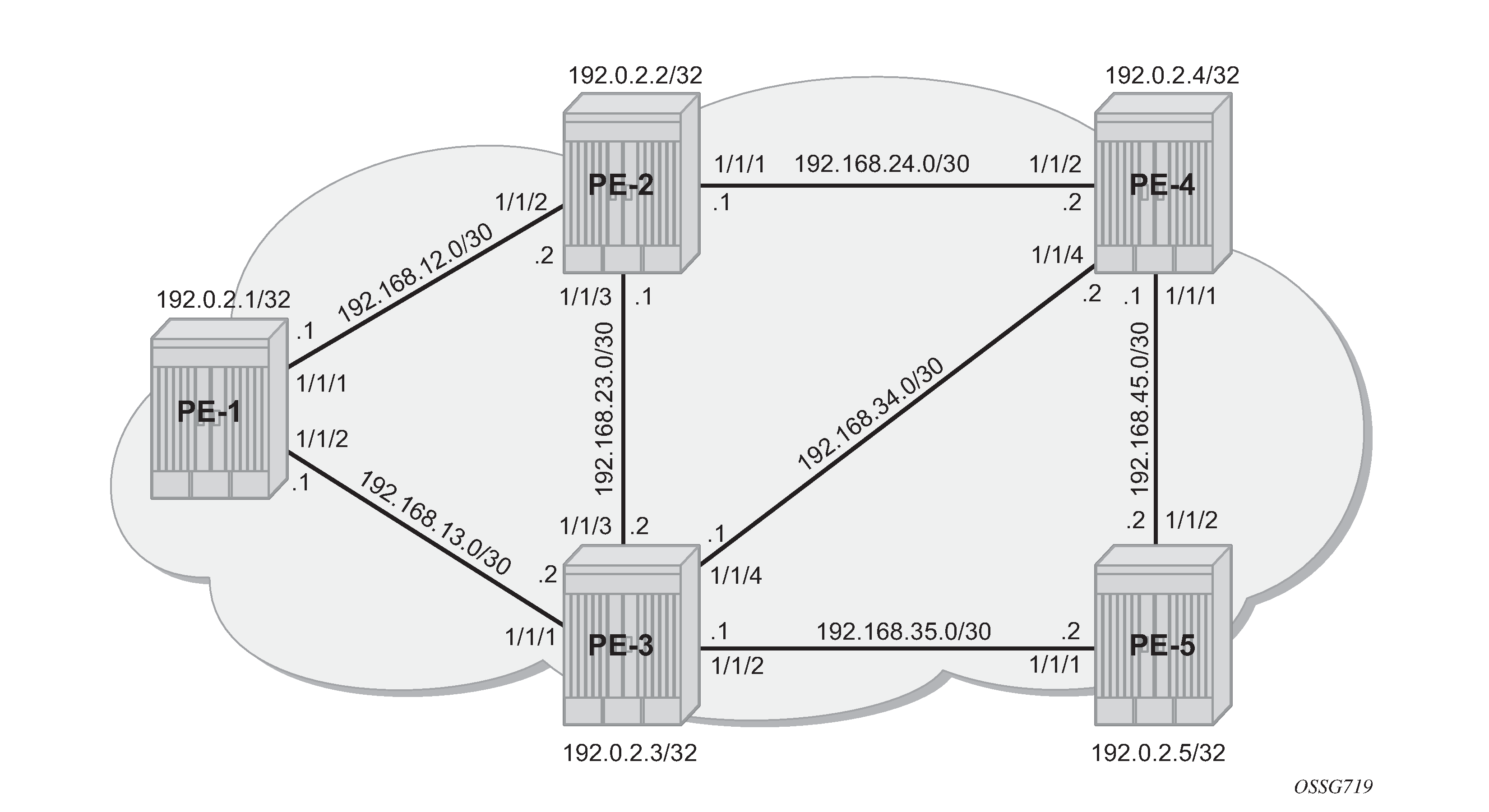
Initial example topology shows the example topology with five PEs in the same autonomous system.
Configure the IP/MPLS network
The system addresses and IP interface addresses are configured according to Initial example topology. An interior gateway protocol (IGP) is needed to distribute routing information on all PEs. In this case, the IGP is IS-IS where each PE is acting as a level 2 router. On PE-1, the IS-IS configuration is as follows. The configuration is similar on the other PEs.
# on PE-1:
configure
    router Base
        isis 0
            level-capability level-2
            level 2
                wide-metrics-only
            exit
            interface "system"
            exit
            interface "int-PE-1-PE-2"
                interface-type point-to-point
            exit
            interface "int-PE-1-PE-3"
                interface-type point-to-point
            exit
            no shutdown
        exit
IS-IS interfaces are set up as type point-to-point to improve convergence because no Designated Router/Backup Designated Router (DR/BDR) election process is done. The show router isis adjacency command on PE-1 verifies that the IS-IS adjacencies are up:
*A:PE-1# show router isis adjacency

===============================================================================
Rtr Base ISIS Instance 0 Adjacency
===============================================================================
System ID                Usage State Hold Interface                     MT-ID
-------------------------------------------------------------------------------
PE-2                     L2    Up    20   int-PE-1-PE-2                 0
PE-3                     L2    Up    27   int-PE-1-PE-3                 0
-------------------------------------------------------------------------------
Adjacencies : 2
===============================================================================
The show router route-table command on PE-1 verifies which IP interface addresses or subnets are known on the PE:
*A:PE-1# show router route-table

===============================================================================
Route Table (Router: Base)
===============================================================================
Dest Prefix[Flags]                            Type    Proto     Age        Pref
      Next Hop[Interface Name]                                    Metric
-------------------------------------------------------------------------------
192.0.2.1/32                                  Local   Local     00h02m20s  0
       system                                                       0
192.0.2.2/32                                  Remote  ISIS      00h01m45s  18
       192.168.12.2                                                 10
192.0.2.3/32                                  Remote  ISIS      00h01m20s  18
       192.168.13.2                                                 10
192.0.2.4/32                                  Remote  ISIS      00h00m58s  18
       192.168.12.2                                                 20
192.0.2.5/32                                  Remote  ISIS      00h00m35s  18
       192.168.13.2                                                 20
192.168.12.0/30                               Local   Local     00h02m20s  0
       int-PE-1-PE-2                                                0
192.168.13.0/30                               Local   Local     00h02m20s  0
       int-PE-1-PE-3                                                0
192.168.23.0/30                               Remote  ISIS      00h01m45s  18
       192.168.12.2                                                 20
192.168.24.0/30                               Remote  ISIS      00h01m45s  18
       192.168.12.2                                                 20
192.168.34.0/30                               Remote  ISIS      00h01m20s  18
       192.168.13.2                                                 20
192.168.35.0/30                               Remote  ISIS      00h01m20s  18
       192.168.13.2                                                 20
192.168.45.0/30                               Remote  ISIS      00h00m58s  18
       192.168.12.2                                                 30
-------------------------------------------------------------------------------
No. of Routes: 12
Flags: n = Number of times nexthop is repeated
       B = BGP backup route available
       L = LFA nexthop available
       S = Sticky ECMP requested
===============================================================================
The show router fib 1 command on PE-1 shows the content of the forwarding information base (FIB):
*A:PE-1# show router fib 1

===============================================================================
FIB Display
===============================================================================
Prefix [Flags]                                              Protocol
  NextHop
-------------------------------------------------------------------------------
192.0.2.1/32                                                LOCAL
  192.0.2.1 (system)
192.0.2.2/32                                                ISIS
  192.168.12.2 (int-PE-1-PE-2)
192.0.2.3/32                                                ISIS
  192.168.13.2 (int-PE-1-PE-3)
192.0.2.4/32                                                ISIS
  192.168.12.2 (int-PE-1-PE-2)
192.0.2.5/32                                                ISIS
  192.168.13.2 (int-PE-1-PE-3)
192.168.12.0/30                                             LOCAL
  192.168.12.0 (int-PE-1-PE-2)
192.168.13.0/30                                             LOCAL
  192.168.13.0 (int-PE-1-PE-3)
192.168.23.0/30                                             ISIS
  192.168.12.2 (int-PE-1-PE-2)
192.168.24.0/30                                             ISIS
  192.168.12.2 (int-PE-1-PE-2)
192.168.34.0/30                                             ISIS
  192.168.13.2 (int-PE-1-PE-3)
192.168.35.0/30                                             ISIS
  192.168.13.2 (int-PE-1-PE-3)
192.168.45.0/30                                             ISIS
  192.168.12.2 (int-PE-1-PE-2)
-------------------------------------------------------------------------------
Total Entries : 12
-------------------------------------------------------------------------------
===============================================================================
Initially, the following default IS-IS Level 2 metric applies to all interfaces.
*A:PE-1# show router isis status | match "L2 Default Metric"
L2 Default Metric    : 10
The next step in the process of setting up the IP/MPLS network is setting up interface-LDP sessions on all interfaces.
# on PE-1:
configure
    router Base
         ldp
            interface-parameters
                interface "int-PE-1-PE-2" dual-stack
                    ipv4
                        no shutdown
                    exit
                    no shutdown
                exit
                interface "int-PE-1-PE-3" dual-stack
                    ipv4
                        no shutdown
                    exit
                    no shutdown
                exit
            exit
            no shutdown
        exit
There is now a full mesh of LDP label switched paths (LSPs) set up between all system interfaces of the PEs, and the tunnel table on PE-1 looks as follows:
*A:PE-1# show router tunnel-table

===============================================================================
IPv4 Tunnel Table (Router: Base)
===============================================================================
Destination           Owner     Encap TunnelId  Pref   Nexthop        Metric
   Color
-------------------------------------------------------------------------------
192.0.2.2/32          ldp       MPLS  65537     9      192.168.12.2   10
192.0.2.3/32          ldp       MPLS  65538     9      192.168.13.2   10
192.0.2.4/32          ldp       MPLS  65539     9      192.168.12.2   20
192.0.2.5/32          ldp       MPLS  65540     9      192.168.13.2   20
-------------------------------------------------------------------------------
Flags: B = BGP or MPLS backup hop available
       L = Loop-Free Alternate (LFA) hop available
       E = Inactive best-external BGP route
       k = RIB-API or Forwarding Policy backup hop
===============================================================================
The LDP LSP metric follows the IGP cost. Optionally, LSP metrics can be applied but that is beyond the scope for this chapter.
Enable LDP FRR and verify
Because LDP FRR is using LFA next-hop computation by the IGP, as described in RFC 5286, LFA must be enabled in the IGP context, as follows:
# on PE-1:
configure
    router Base
        isis 0
            loopfree-alternate
The show router isis status command on PE-1 verifies that LFA is enabled in IS-IS:
*A:PE-1# show router isis status | match Loopfree
Loopfree-Alternate   : Enabled
After enabling LFA inside the IGP context, FRR needs to be enabled within the ldp context, as follows:
# on PE-1:
configure
    router Base
        ldp
            fast-reroute
The show router ldp status command on PE-1 verifies that FRR is enabled in LDP:
*A:PE-1# show router ldp status | match FRR
FRR                : Enabled              Mcast Upstream FRR   : Disabled
Mcast Upst ASBR FRR: Disabled
This chapter describes FRR for unicast LDP. For multicast upstream FRR, see the Multicast Label Distribution Protocol chapter. After these two CLI commands, the software computes for each LDP FEC in the network both a primary and a backup NHLFE and uploads it to the IOM/IMM. The primary NHLFE corresponds to the label of the FEC received from the primary next-hop as per standard LDP resolution of the FEC prefix in the Routing Table Manager (RTM). The backup NHLFE corresponds to the label received for the same FEC from an LFA next hop.
For point-to-point interfaces, when multiple LFA next hops are found for a primary next hop, the following selection criteria are used:
It will pick the node-protect type in favor of the link-protect type.
If there is more than one LFA next hop within the selected type, then it will pick one based on the lowest cost.
If more than one LFA next hop with the same cost, SPF will select the first one. This is not a deterministic selection and will vary following each SPF calculation.
Several show commands are possible to display LFA information:
The show router isis statistics command shows the number of LFA runs on a specific node.
*A:PE-1# show router isis statistics

===============================================================================
Rtr Base ISIS Instance 0 Statistics
===============================================================================
---snip---
LFA Statistics
LFA Runs          : 1
 Last scheduled   : 03/10/2021 16:05:08
Partial LFA Runs  : 0

RLFA Statistics
RLFA Runs         : 0
---snip---
Remote LFA (RLFA) statistics and Topology-independent LFA (TI-LFA) statistics have been removed from the preceding output, because they are beyond the scope of this chapter. RLFA and TI-LFA are used in segment routing and described in chapters Segment Routing with IS-IS Control Plane and Topology-Independent Loop-Free Alternate for Link Protection
The show router isis lfa-coverage command performs a mathematical calculation between the number of nodes and IPv4/IPv6 routes in the network versus present LFA next-hop protections. In the example topology (see Initial example topology), all IS-IS links have a default level 2 metric of 10. This results in all four nodes and all IS-IS routes learned by PE-1 being 100% LFA protected (link or node), as follows:
*A:PE-1# show router isis lfa-coverage

===============================================================================
Rtr Base ISIS Instance 0 LFA Coverage
===============================================================================
Topology         Level   Node           IPv4                IPv6
-------------------------------------------------------------------------------
IPV4 Unicast     L1      0/0(0%)        9/9(100%)           0/0(0%)
IPV6 Unicast     L1      0/0(0%)        0/0(0%)             0/0(0%)
IPV4 Multicast   L1      0/0(0%)        0/0(0%)             0/0(0%)
IPV6 Multicast   L1      0/0(0%)        0/0(0%)             0/0(0%)
IPV4 Unicast     L2      4/4(100%)      9/9(100%)           0/0(0%)
IPV6 Unicast     L2      0/0(0%)        0/0(0%)             0/0(0%)
IPV4 Multicast   L2      0/0(0%)        0/0(0%)             0/0(0%)
IPV6 Multicast   L2      0/0(0%)        0/0(0%)             0/0(0%)
===============================================================================
The show router isis topology lfa detail command shows the LFA protection type (link or node), as follows:
*A:PE-1# show router isis topology lfa detail

===============================================================================
Rtr Base ISIS Instance 0 Topology Table
===============================================================================
-------------------------------------------------------------------------------
IS-IS IP paths (MT-ID 0),   Level 2
-------------------------------------------------------------------------------
Node      : PE-2.00
Nexthop   : PE-2
Interface : int-PE-1-PE-2
SNPA      : none                             Metric      : 10

LFA nh    : PE-3
LFA intf  : int-PE-1-PE-3                    LFA Metric  : 20
LFA type  : linkProtection

Node      : PE-3.00
Nexthop   : PE-3
Interface : int-PE-1-PE-3
SNPA      : none                             Metric      : 10

LFA nh    : PE-2
LFA intf  : int-PE-1-PE-2                    LFA Metric  : 20
LFA type  : linkProtection

Node      : PE-4.00
Nexthop   : PE-2
Interface : int-PE-1-PE-2
SNPA      : none                             Metric      : 20

LFA nh    : PE-3
LFA intf  : int-PE-1-PE-3                    LFA Metric  : 20
LFA type  : nodeProtection

Node      : PE-5.00
Nexthop   : PE-3
Interface : int-PE-1-PE-3
SNPA      : none                             Metric      : 20

LFA nh    : PE-2
LFA intf  : int-PE-1-PE-2                    LFA Metric  : 30
LFA type  : linkProtection

===============================================================================
The show router route-table command adds an ‛L’ flag as reference that the associated prefix is having also an LFA next hop available.
*A:PE-1# show router route-table 192.0.2.4

===============================================================================
Route Table (Router: Base)
===============================================================================
Dest Prefix[Flags]                            Type    Proto     Age        Pref
      Next Hop[Interface Name]                                    Metric
-------------------------------------------------------------------------------
192.0.2.4/32 [L]                              Remote  ISIS      00h51m18s  18
       192.168.12.2                                                 20
-------------------------------------------------------------------------------
No. of Routes: 1
Flags: n = Number of times nexthop is repeated
       B = BGP backup route available
       L = LFA nexthop available
       S = Sticky ECMP requested
===============================================================================
The show router route-table alternative command or show router isis routes alternative command show detailed interface address information used by the LFA calculation:
*A:PE-1# show router route-table alternative 192.0.2.4

===============================================================================
Route Table (Router: Base)
===============================================================================
Dest Prefix[Flags]                            Type    Proto     Age        Pref
      Next Hop[Interface Name]                                    Metric
      Alt-NextHop                                                Alt-
                                                                Metric
-------------------------------------------------------------------------------
192.0.2.4/32                                  Remote  ISIS      00h51m18s  18
       192.168.12.2                                                 20
       192.168.13.2 (LFA)                                           20
-------------------------------------------------------------------------------
No. of Routes: 1
Flags: n = Number of times nexthop is repeated
       Backup = BGP backup route
       LFA = Loop-Free Alternate nexthop
       S = Sticky ECMP requested
===============================================================================
*A:PE-1# show router isis routes 192.0.2.4 alternative

===============================================================================
Rtr Base ISIS Instance 0 Route Table (alternative)
===============================================================================
Prefix[Flags]                     Metric     Lvl/Typ     Ver.  SysID/Hostname
  NextHop                                                MT     AdminTag/SID[F]
Alt-Nexthop                                              Alt-   Alt-Type
                                                        Metric
-------------------------------------------------------------------------------
192.0.2.4/32                      20         2/Int.      5     PE-2
   192.168.12.2                                            0       0
   192.168.13.2(L)                                        20      NP
-------------------------------------------------------------------------------
No. of Routes: 1 (1 path)
-------------------------------------------------------------------------------
Flags        : L = Loop-Free Alternate nexthop
Alt-Type     : LP = linkProtection, NP = nodeProtection
SID[F]       : R  = Re-advertisement
               N  = Node-SID
               nP = no penultimate hop POP
               E  = Explicit-Null
               V  = Prefix-SID carries a value
               L  = value/index has local significance
===============================================================================
On PE-1, PE-4 (192.0.2.4/32) has a primary SPF next-hop pointing toward PE-2 (192.168.12.2) and an LFA next-hop pointing toward PE-3 (192.168.13.2).
The Inequality 3 formula on PE-1 for prefix 192.0.2.4/32 results in the following:
Inequality 3:
[SP(backup NHR, D) < {SP(backup NHR, PN) + SP(PN, D)}] or
[SP (PE-3, PE-4) < {SP (PE-3, PE-2) + SP(PE-2, PE-4)}] or
[10 < {10 + 10}]
This means that Inequality 3 is met. The calculated LFA next-hop for prefix 192.0.2.4/32 on PE-1 is protecting node PE-2, see Initial example topology for a graphical representation.
The show router ldp bindings command displays the Label Information Base (LIB). A BU flag is present in case the associated label is used as backup NHLFE for the prefix. As an example, a display on PE-1 for prefix PE-4 is as follows.
This is only possible because the SR OS LDP implementation is using liberal retention mode which means that every label mapping received by a peer is retained regardless of whether the LSR is the next hop for the advertised mapping.
*A:PE-1# show router ldp bindings prefixes prefix 192.0.2.4/32

===============================================================================
LDP Bindings (IPv4 LSR ID 192.0.2.1)
             (IPv6 LSR ID ::)
===============================================================================
Label Status:
        U - Label In Use, N - Label Not In Use, W - Label Withdrawn
        WP - Label Withdraw Pending, BU - Alternate For Fast Re-Route
        e - Label ELC
FEC Flags:
        LF - Lower FEC, UF - Upper FEC, M - Community Mismatch,
        BA - ASBR Backup FEC
===============================================================================
LDP IPv4 Prefix Bindings
===============================================================================
Prefix
Peer                                        FEC-Flags
IgrLbl                                      EgrLbl
EgrNextHop                                  EgrIntf/LspId
-------------------------------------------------------------------------------
192.0.2.4/32
192.0.2.2:0
524284N                                     524284
192.168.12.2                                1/1/1

192.0.2.4/32
192.0.2.3:0
524284U                                     524284BU
192.168.13.2                                1/1/2

-------------------------------------------------------------------------------
No. of IPv4 Prefix Bindings: 2
===============================================================================
The show router ldp bindings active command displays the label forwarding information base (LFIB). Also, the BU flag is present and, in addition, a reference to the label action itself: pop for eLER, push for iLER and swap for LSR.
*A:PE-1# show router ldp bindings active prefixes prefix 192.0.2.4/32

===============================================================================
LDP Bindings (IPv4 LSR ID 192.0.2.1)
             (IPv6 LSR ID ::)
===============================================================================
Label Status:
        U - Label In Use, N - Label Not In Use, W - Label Withdrawn
        WP - Label Withdraw Pending, BU - Alternate For Fast Re-Route
        e - Label ELC
FEC Flags:
        LF - Lower FEC, UF - Upper FEC, M - Community Mismatch,
        BA - ASBR Backup FEC
        (S) - Static           (M) - Multi-homed Secondary Support
        (B) - BGP Next Hop     (BU) - Alternate Next-hop for Fast Re-Route
        (I) - SR-ISIS Next Hop (O) - SR-OSPF Next Hop
        (C) - FEC resolved with class-based-forwarding
===============================================================================
LDP IPv4 Prefix Bindings (Active)
===============================================================================
Prefix                                      Op
IngLbl                                      EgrLbl
EgrNextHop                                  EgrIf/LspId
-------------------------------------------------------------------------------
192.0.2.4/32                                Push
  --                                        524284
192.168.12.2                                1/1/1

192.0.2.4/32                                Push
  --                                        524284BU
192.168.13.2                                1/1/2

192.0.2.4/32                                Swap
524284                                      524284
192.168.12.2                                1/1/1

192.0.2.4/32                                Swap
524284                                      524284BU
192.168.13.2                                1/1/2

-------------------------------------------------------------------------------
No. of IPv4 Prefix Active Bindings: 4
===============================================================================
Enable synchronization timer
Within an MPLS network using LDP, it is common practice to enable a synchronization timer between LDP and the IGP. Also, when LDP FRR is enabled, a situation can occur in which a synchronization timer between IGP and LDP will help: the revert scenario. When the interface for the previous primary next hop is restored, IGP may re-converge before LDP completed the FEC exchange with its neighbor over that interface. This may cause LDP to remove the LFA next hop from the FEC and blackhole traffic.
In order to avoid traffic being blackholed, it is recommended to first enable IGP-LDP synchronization on the interface. The time is expressed in seconds and can have a value between 1 and 1800 seconds. It is also possible to configure an end-of-LIB option to optimize the synchronization time, see the LDP-IGP Synchronization chapter. On PE-1, the following configures the LDP synchronization timer with a value of 10 seconds on the interfaces "int-PE-1-PE-2" and "int-PE-1-PE-3":
# on PE-1:
configure
    router Base
        interface "int-PE-1-PE-2"
            ldp-sync-timer 10
        exit
        interface "int-PE-1-PE-3"
            ldp-sync-timer 10
        exit
The configuration on the other nodes is similar.
When this timer is enabled, it means that when an interface is restored, the IGP will advertise this link in the network with an infinite metric. The ldp-sync-timer is started, LDP adjacencies are brought up together with a label exchange. After the ldp-sync-timer expires, the normal metric is advertised in the network again.
Verify data path
Data path verification is performed using a Layer 2 Epipe service. Traffic generator ports are connected toward PE-1 and PE-5, and an Epipe service is created using an MPLS LDP based Service Distribution Path (SDP) on both PE-1 and PE-5. The service configuration on PE-1 is as follows:
# on PE-1:
configure
    service
        sdp 15 mpls create
            far-end 192.0.2.5
            ldp
            no shutdown
        exit
        epipe 1 name "Epipe 1" customer 1 create
            service-mtu 1450
            sap 1/1/3:1 create
            exit
            spoke-sdp 15:1 create
            exit
            no shutdown
        exit
The service configuration on PE-5 is similar.
The IS-IS Level 2 metric value on the interface between PE-4 and PE-5 is decreased to 5, see Data verification in the direction from PE-1 to PE-5 using Epipe service.
# on PE-4:
configure
    router Base
        isis 0
            interface "int-PE-4-PE-5"
                level 2
                    metric 5
# on PE-5:
configure
    router Base
        isis 0
            interface "int-PE-5-PE-4"
                level 2
                    metric 5
Data verification in the direction from PE-1 to PE-5 using Epipe service shows the preferred data path for Epipe 1 via PE-3 and the LFA for PE-5 that is protecting node PE-3.
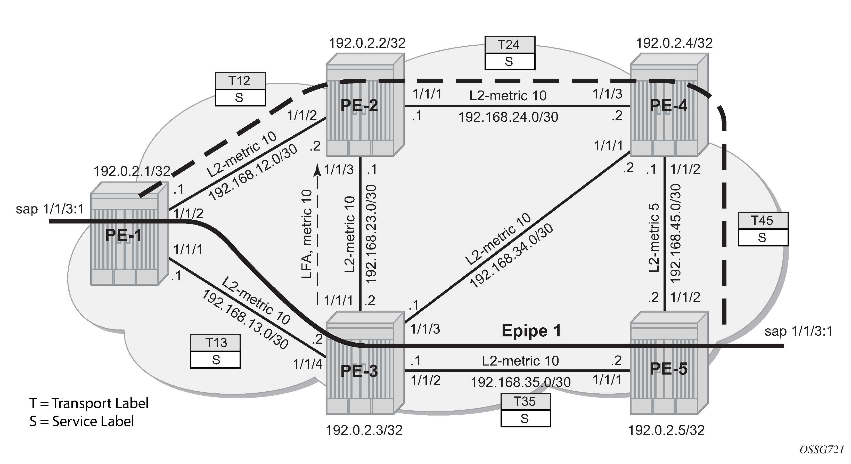
In this setup, the following LFA for prefix PE-5 from PE-1 is protecting the node PE-3:
*A:PE-1# show router isis topology lfa detail

===============================================================================
Rtr Base ISIS Instance 0 Topology Table
===============================================================================
-------------------------------------------------------------------------------
IS-IS IP paths (MT-ID 0),   Level 2
-------------------------------------------------------------------------------
---snip---
Node      : PE-5.00
Nexthop   : PE-3
Interface : int-PE-1-PE-3
SNPA      : none                             Metric      : 20

LFA nh    : PE-2
LFA intf  : int-PE-1-PE-2                    LFA Metric  : 25
LFA type  : nodeProtection

===============================================================================
*A:PE-1# show router isis routes alternative 192.0.2.5

===============================================================================
Rtr Base ISIS Instance 0 Route Table (alternative)
===============================================================================
Prefix[Flags]                     Metric     Lvl/Typ     Ver.  SysID/Hostname
  NextHop                                                MT     AdminTag/SID[F]
Alt-Nexthop                                              Alt-   Alt-Type
                                                        Metric
-------------------------------------------------------------------------------
192.0.2.5/32                      20         2/Int.      6     PE-3
   192.168.13.2                                            0       0
   192.168.12.2(L)                                        25      NP
-------------------------------------------------------------------------------
No. of Routes: 1 (1 path)
-------------------------------------------------------------------------------
Flags        : L = Loop-Free Alternate nexthop
Alt-Type     : LP = linkProtection, NP = nodeProtection
SID[F]       : R  = Re-advertisement
               N  = Node-SID
               nP = no penultimate hop POP
               E  = Explicit-Null
               V  = Prefix-SID carries a value
               L  = value/index has local significance
===============================================================================
In normal conditions, MPLS traffic from PE-1 toward PE-5 over Epipe 1 will have two MPLS labels: an outer (transport) label given by LDP protocol, swapped on each intermediate LSR and an inner (service) label given by T-LDP, the same end-to-end. See the following show commands.
The T-LDP service label is S (524282):
*A:PE-1# show router ldp bindings services service-id 1

===============================================================================
LDP Bindings (IPv4 LSR ID 192.0.2.1)
             (IPv6 LSR ID ::)
===============================================================================
Label Status:
        U - Label In Use, N - Label Not In Use, W - Label Withdrawn
        S - Status Signaled Up,  D - Status Signaled Down, e - Label ELC
        WP - Label Withdraw Pending, BU - Alternate For Fast Re-Route
Service Type:
        E - Epipe Service, V - VPLS Service, M - Mirror Service
        A - Apipe Service, F - Fpipe Service, I - IES Service, R - VPRN service
        P - Ipipe Service, C - Cpipe Service
FEC Flags:
        LF - Lower FEC, UF - Upper FEC, M - Community Mismatch,
        BA - ASBR Backup FEC
===============================================================================
LDP Service FEC 128 Bindings
===============================================================================
Type                                          VCId       SDPId             LMTU
Peer                                          SvcId      IngLbl            RMTU
                                                         EgrLbl
-------------------------------------------------------------------------------
E-Eth                                         1          15                1436
192.0.2.5:0                                   1          524282U           1436
                                                         524282S

-------------------------------------------------------------------------------
No. of VC Labels: 1
===============================================================================

===============================================================================
LDP Service FEC 129 Bindings
===============================================================================
SAII                                            AGII        IngLbl         LMTU
TAII                                            Type        EgrLbl         RMTU
Peer                                            SvcId       SDPId
-------------------------------------------------------------------------------
No Matching Entries Found
===============================================================================
The transport LDP label between PE-1 and PE-3 for prefix 192.0.2.5/32 is T13 (524283):
*A:PE-1# show router ldp bindings active prefixes prefix 192.0.2.5/32

===============================================================================
LDP Bindings (IPv4 LSR ID 192.0.2.1)
             (IPv6 LSR ID ::)
===============================================================================
Label Status:
        U - Label In Use, N - Label Not In Use, W - Label Withdrawn
        WP - Label Withdraw Pending, BU - Alternate For Fast Re-Route
        e - Label ELC
FEC Flags:
        LF - Lower FEC, UF - Upper FEC, M - Community Mismatch,
        BA - ASBR Backup FEC
        (S) - Static           (M) - Multi-homed Secondary Support
        (B) - BGP Next Hop     (BU) - Alternate Next-hop for Fast Re-Route
        (I) - SR-ISIS Next Hop (O) - SR-OSPF Next Hop
        (C) - FEC resolved with class-based-forwarding
===============================================================================
LDP IPv4 Prefix Bindings (Active)
===============================================================================
Prefix                                      Op
IngLbl                                      EgrLbl
EgrNextHop                                  EgrIf/LspId
-------------------------------------------------------------------------------
192.0.2.5/32                                Push
  --                                        524283
192.168.13.2                                1/1/2

192.0.2.5/32                                Push
  --                                        524283BU
192.168.12.2                                1/1/1

192.0.2.5/32                                Swap
524283                                      524283
192.168.13.2                                1/1/2

192.0.2.5/32                                Swap
524283                                      524283BU
192.168.12.2                                1/1/1

-------------------------------------------------------------------------------
No. of IPv4 Prefix Active Bindings: 4
===============================================================================
The transport LDP label between PE-3 and PE-5 for prefix 192.0.2.5/32 is T35 (524287):
*A:PE-3# show router ldp bindings active prefixes prefix 192.0.2.5/32

===============================================================================
LDP Bindings (IPv4 LSR ID 192.0.2.3)
             (IPv6 LSR ID ::)
===============================================================================
Label Status:
        U - Label In Use, N - Label Not In Use, W - Label Withdrawn
        WP - Label Withdraw Pending, BU - Alternate For Fast Re-Route
        e - Label ELC
FEC Flags:
        LF - Lower FEC, UF - Upper FEC, M - Community Mismatch,
        BA - ASBR Backup FEC
        (S) - Static           (M) - Multi-homed Secondary Support
        (B) - BGP Next Hop     (BU) - Alternate Next-hop for Fast Re-Route
        (I) - SR-ISIS Next Hop (O) - SR-OSPF Next Hop
        (C) - FEC resolved with class-based-forwarding
===============================================================================
LDP IPv4 Prefix Bindings (Active)
===============================================================================
Prefix                                      Op
IngLbl                                      EgrLbl
EgrNextHop                                  EgrIf/LspId
-------------------------------------------------------------------------------
192.0.2.5/32                                Push
  --                                        524287
192.168.35.2                                1/1/2

192.0.2.5/32                                Push
  --                                        524283BU
192.168.34.2                                1/1/4

192.0.2.5/32                                Swap
524283                                      524287
192.168.35.2                                1/1/2

192.0.2.5/32                                Swap
524283                                      524283BU
192.168.34.2                                1/1/4

-------------------------------------------------------------------------------
No. of IPv4 Prefix Active Bindings: 4
===============================================================================
When PE-3 reboots, PE-1 performs an immediate swap to LFA next-hop for prefix 192.0.2.5/32 bypassing PE-3. The service label remains the same; only the transport labels can change on the network ports from PE-1 to PE-2, from PE-2 to PE-4, and from PE-4 to PE-5. See the following show commands.
The LDP FRR MPLS label stack will never contain more than two labels. This is different from RSVP-TE FRR facility mode which uses a three-label MPLS stack.
The T-LDP service label is S (524282):
*A:PE-1# show router ldp bindings services service-id 1

===============================================================================
LDP Bindings (IPv4 LSR ID 192.0.2.1)
             (IPv6 LSR ID ::)
===============================================================================
Label Status:
        U - Label In Use, N - Label Not In Use, W - Label Withdrawn
        S - Status Signaled Up,  D - Status Signaled Down, e - Label ELC
        WP - Label Withdraw Pending, BU - Alternate For Fast Re-Route
Service Type:
        E - Epipe Service, V - VPLS Service, M - Mirror Service
        A - Apipe Service, F - Fpipe Service, I - IES Service, R - VPRN service
        P - Ipipe Service, C - Cpipe Service
FEC Flags:
        LF - Lower FEC, UF - Upper FEC, M - Community Mismatch,
        BA - ASBR Backup FEC
===============================================================================
LDP Service FEC 128 Bindings
===============================================================================
Type                                          VCId       SDPId             LMTU
Peer                                          SvcId      IngLbl            RMTU
                                                         EgrLbl
-------------------------------------------------------------------------------
E-Eth                                         1          15                1436
192.0.2.5:0                                   1          524282U           1436
                                                         524282S

-------------------------------------------------------------------------------
No. of VC Labels: 1
===============================================================================
---snip---
The transport LDP label value between PE-1 and PE-2 for prefix 192.0.2.5/32 is the same label (previously tagged as BU) as before the node failure event: T12 (524283):
*A:PE-1# show router ldp bindings active prefixes prefix 192.0.2.5/32

===============================================================================
---snip---
===============================================================================
LDP IPv4 Prefix Bindings (Active)
===============================================================================
Prefix                                      Op
IngLbl                                      EgrLbl
EgrNextHop                                  EgrIf/LspId
-------------------------------------------------------------------------------
192.0.2.5/32                                Push
  --                                        524283
192.168.12.2                                1/1/1

192.0.2.5/32                                Swap
524283                                      524283
192.168.12.2                                1/1/1

-------------------------------------------------------------------------------
No. of IPv4 Prefix Active Bindings: 2
===============================================================================
The transport LDP label between PE-2 and PE-4 for prefix 192.0.2.5/32 is T24 (524283):
*A:PE-2# show router ldp bindings active prefixes prefix 192.0.2.5/32

===============================================================================
---snip---
===============================================================================
LDP IPv4 Prefix Bindings (Active)
===============================================================================
Prefix                                      Op
IngLbl                                      EgrLbl
EgrNextHop                                  EgrIf/LspId
-------------------------------------------------------------------------------
192.0.2.5/32                                Push
  --                                        524283
192.168.24.2                                1/1/1

192.0.2.5/32                                Swap
524283                                      524283
192.168.24.2                                1/1/1

-------------------------------------------------------------------------------
No. of IPv4 Prefix Active Bindings: 2
===============================================================================
The transport LDP label between PE-4 and PE-5 for prefix 192.0.2.5/32 is T45 (524287):
*A:PE-4# show router ldp bindings active prefixes prefix 192.0.2.5/32

===============================================================================
---snip---
===============================================================================
LDP IPv4 Prefix Bindings (Active)
===============================================================================
Prefix                                      Op
IngLbl                                      EgrLbl
EgrNextHop                                  EgrIf/LspId
-------------------------------------------------------------------------------
192.0.2.5/32                                Push
  --                                        524287
192.168.45.2                                1/1/1

192.0.2.5/32                                Swap
524283                                      524287
192.168.45.2                                1/1/1

-------------------------------------------------------------------------------
No. of IPv4 Prefix Active Bindings: 2
===============================================================================
Additional topics
Metric change
On PE-4 and PE-5, the default level 2 metrics are restored, as follows:
# on PE-4:
configure
    router Base
        isis 0
            interface "int-PE-4-PE-5"
                level 2
                    no metric
# on PE-5:
configure
    router Base
        isis 0
            interface "int-PE-5-PE-4"
                level 2
                    no metric
When the IS-IS level 2 metric between PE-2 and PE-3 changes to 30, then 100% LFA coverage is no longer possible. The IS-IS level 2 metric is modified as follows:
# on PE-2:
configure
    router Base
        isis 0
            interface "int-PE-2-PE-3"
                level 2
                    metric 30
# on PE-3:
configure
    router Base
        isis 0
            interface "int-PE-3-PE-2"
                level 2
                    metric 30
On PE-1, Inequality 3 formula will find LFA next-hop coverages for prefix PE-4 and PE-5. Inequality formula 1 will find LFA next-hop coverages for prefix PE-4, PE-5, and the subnet between PE-4 and PE-5.
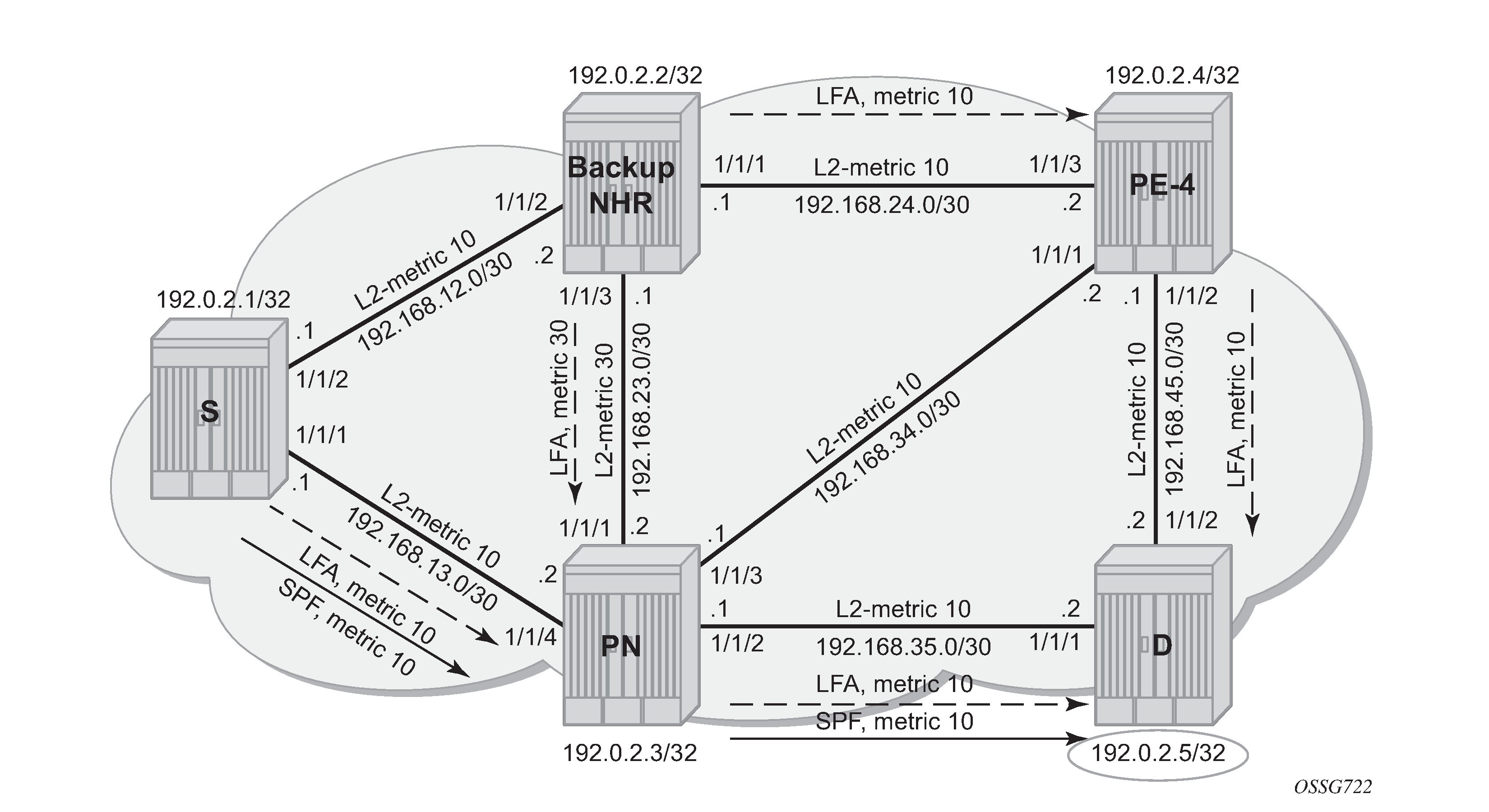
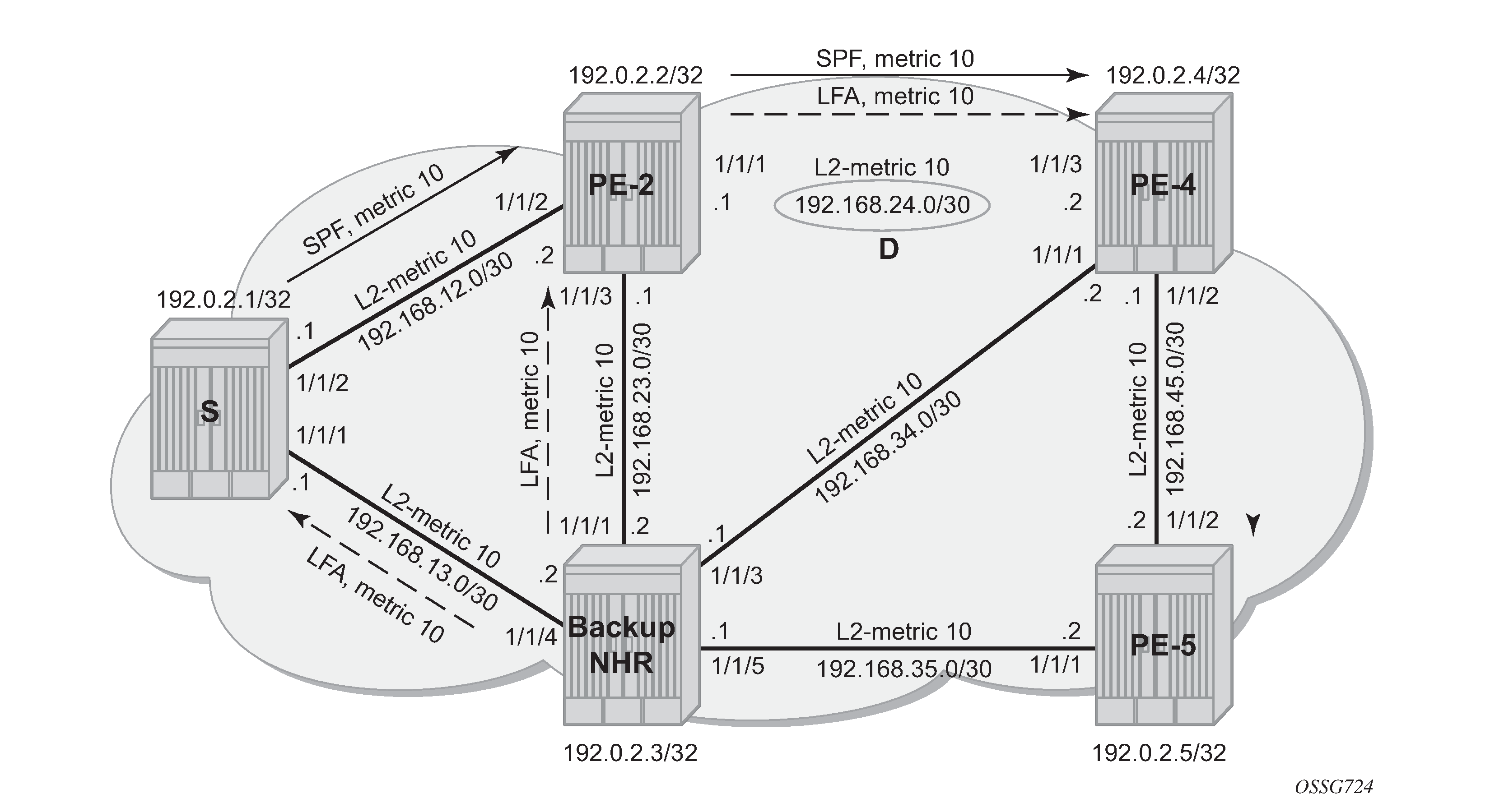
Both inequality formulas are visualized in LFA computation: Inequality 3 for prefix PE-5 (D) on PE-1 (S) and LFA computation: Inequality 1 for prefix PE-5 (D) on PE-1 (S) for prefix 192.0.2.5/32 (= PE-5) on PE-1 which serves as the source node for LFA next-hop computation.
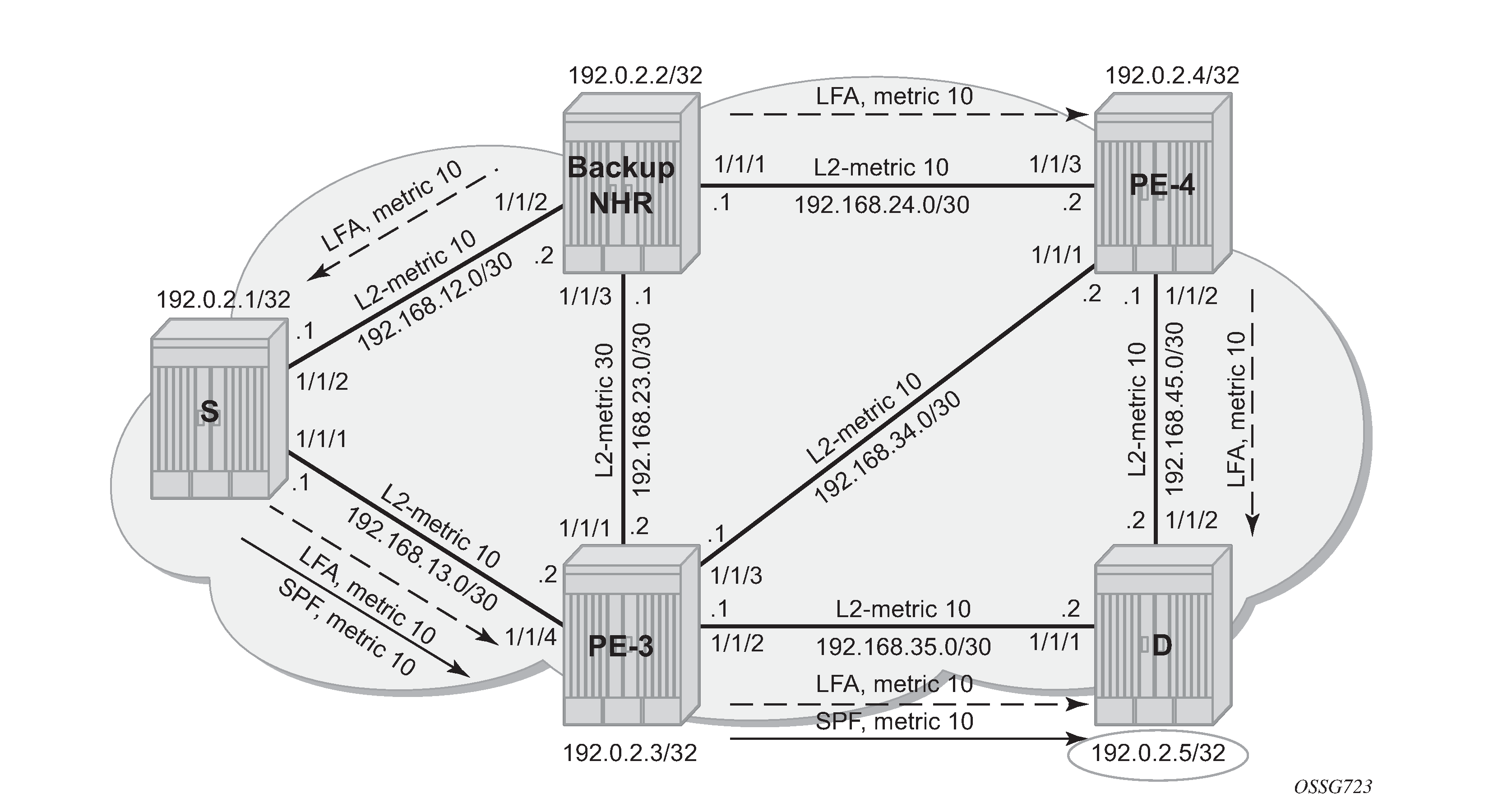
Inequality 3 formula:
[SP(backup NHR, D) < {SP(backup NHR, PN) + SP(PN, D)}]
For a node LFA next-hop calculation of prefix 192.0.2.5/32 (D) on PE-1, this means that the shortest path from backup next-hop router PE-2 toward destination PE-5 must be smaller than the sum of the shortest path from backup next-hop router PE-2 toward protected node PE-3 with the shortest path from protected node PE-3 to destination PE-5.
The shortest path from backup next-hop router PE-2 toward destination PE-5 is going via PE-4, using IS-IS level 2 metric 10 for interface ‟int-PE-2-PE-4” and IS-IS level 2 metric 10 for interface ‟int-PE-4-PE-5”. The shortest path from backup next-hop router (PE-2) toward protected node (PE-3) uses IS-IS level 2 metric 30 for interface ‟int-PE-2-PE-3”. The shortest path from protected node (PE-3) to destination (PE-5) uses IS-IS level 2 metric 10 for interface ‟int-PE-3-PE-5”. The calculation is as follows:
Prefix 192.0.2.5/32: SP (PE-2, PE-5) < SP (PE-2, PE-3) + SP (PE-3, PE-5)
                                10 + 10  < 30 + 10 => OK
Inequality 1 formula:
SP(backup NHR, D) < {SP(backup NHR, S) + SP(S, D)}
For a link LFA next-hop calculation of prefix 192.0.2.5/32 (D) on PE-1, this means that the shortest path from backup next-hop router PE-2 toward destination PE-5 must be smaller than the sum of the shortest path from backup next-hop router PE-2 toward source PE-1 with the shortest path from source PE-1 to destination PE-5.
The shortest path from backup next-hop router PE-2 toward destination PE-5 is going over PE-4, using IS-IS level 2 metric 10 for interface ‟int-PE-2-PE-4” and IS-IS level 2 metric 10 for interface ‟int-PE-4-PE-5”. The shortest path from backup next-hop router PE-2 toward source PE-1 uses IS-IS level 2 metric 10 for interface ‟int-PE-2-PE-1”. The shortest path from source PE-1 to destination PE-5 follows the normal SPF calculation, going over PE-3, using IS-IS level 2 metric 10 for interface ‟int-PE-1-PE-3”, and IS-IS level 2 metric 10 for interface ‟int-PE-3-PE-5”.
The calculation is as follows:
Prefix 192.0.2.5/32 :  SP(PE-2,PE-5) < SP(PE-2,PE-1) + SP(PE-1,PE-5)
                          10 + 10    <    10 + (10 + 10)            => OK
For completeness, all the other Inequality 1 calculations on PE-1 are as follows:
Prefix 192.0.2.2/32 :  SP(PE-3,PE-2) < SP(PE-3,PE-1) + SP(PE-1,PE-2)
                              30     <      10 + 10                       => NOK
Prefix 192.0.2.3/32 :  SP(PE-2,PE-3) < SP(PE-2,PE-1) + SP(PE-1,PE-3)
                              30     <      10 + 10                       => NOK
Prefix 192.0.2.4/32 :  SP(PE-3,PE-4) < SP(PE-3,PE-1) + SP(PE-1,PE-4)
                              10     <      10 + (10 + 10)                => OK
Prefix 192.168.23.0/30 :  SP(PE-3,D) < SP(PE-3,PE-1) + SP(PE-1,D)
                              30     <      10 + (10 + 10)                => NOK
Prefix 192.168.24.0/30 :  SP(PE-3,D) < SP(PE-3,PE-1) + SP(PE-1,D)
                           30 + 10   <      10 + (10 + 10)                => NOK
Prefix 192.168.34.0/30 :  SP(PE-2,D) < SP(PE-2,PE-1) + SP(PE-1,D)
                           30 + 10   <      10 + (10 + 10)                => NOK
Prefix 192.168.35.0/30 :  SP(PE-2,D) < SP(PE-2,PE-1) + SP(PE-1,D)
                           30 + 10   <      10 + (10 + 10)                => NOK
Prefix 192.168.45.0/30 :  SP(PE-3,D) < SP(PE-3,PE-1) + SP(PE-1,D)
                           10 + 10   <      10 + (10 + 10 + 10)           => OK
Considering all Inequality 1 calculations, only three of these are valid (OK).
In SR OS, the show router isis lfa-coverage summary command exists for LFA coverage on the router:
*A:PE-1# show router isis lfa-coverage

===============================================================================
Rtr Base ISIS Instance 0 LFA Coverage
===============================================================================
Topology         Level   Node           IPv4                IPv6
-------------------------------------------------------------------------------
IPV4 Unicast     L1      0/0(0%)        3/9(33%)            0/0(0%)
IPV6 Unicast     L1      0/0(0%)        0/0(0%)             0/0(0%)
IPV4 Multicast   L1      0/0(0%)        0/0(0%)             0/0(0%)
IPV6 Multicast   L1      0/0(0%)        0/0(0%)             0/0(0%)
IPV4 Unicast     L2      2/4(50%)       3/9(33%)            0/0(0%)
IPV6 Unicast     L2      0/0(0%)        0/0(0%)             0/0(0%)
IPV4 Multicast   L2      0/0(0%)        0/0(0%)             0/0(0%)
IPV6 Multicast   L2      0/0(0%)        0/0(0%)             0/0(0%)
===============================================================================
The show router route-table alternative command on PE-1 shows which prefixes are protected:
*A:PE-1# show router route-table alternative

===============================================================================
Route Table (Router: Base)
===============================================================================
Dest Prefix[Flags]                            Type    Proto     Age        Pref
      Next Hop[Interface Name]                                    Metric
      Alt-NextHop                                                Alt-
                                                                Metric
-------------------------------------------------------------------------------
192.0.2.1/32                                  Local   Local     01h18m13s  0
       system                                                       0
192.0.2.2/32                                  Remote  ISIS      01h17m39s  18
       192.168.12.2                                                 10
192.0.2.3/32                                  Remote  ISIS      00h04m42s  18
       192.168.13.2                                                 10
192.0.2.4/32                                  Remote  ISIS      01h16m52s  18
       192.168.12.2                                                 20
       192.168.13.2 (LFA)                                           20
192.0.2.5/32                                  Remote  ISIS      00h04m33s  18
       192.168.13.2                                                 20
       192.168.12.2 (LFA)                                           30
192.168.12.0/30                               Local   Local     01h18m13s  0
       int-PE-1-PE-2                                                0
192.168.13.0/30                               Local   Local     01h18m13s  0
       int-PE-1-PE-3                                                0
192.168.23.0/30                               Remote  ISIS      00h00m51s  18
       192.168.12.2                                                 40
192.168.24.0/30                               Remote  ISIS      01h17m39s  18
       192.168.12.2                                                 20
192.168.34.0/30                               Remote  ISIS      00h04m42s  18
       192.168.13.2                                                 20
192.168.35.0/30                               Remote  ISIS      00h04m42s  18
       192.168.13.2                                                 20
192.168.45.0/30                               Remote  ISIS      00h02m12s  18
       192.168.12.2                                                 30
       192.168.13.2 (LFA)                                           30
-------------------------------------------------------------------------------
No. of Routes: 12
Flags: n = Number of times nexthop is repeated
       Backup = BGP backup route
       LFA = Loop-Free Alternate nexthop
       S = Sticky ECMP requested
===============================================================================
The default IS-IS level 2 metrics are restored, as follows:
# on PE-2:
configure
    router Base
        isis 0
            interface "int-PE-2-PE-3"
                level 2
                    no metric
# on PE-3:
configure
    router Base
        isis 0
            interface "int-PE-3-PE-2"
                level 2
                    no metric
IS-IS overload
As stated in RFC 3137, OSPF Stub Router Advertisement, sometimes it is useful and desirable for a router not to be a transit node. For those cases, it is also desirable not to have that router used as transit node during the LFA next-hop computation. Within the IS-IS protocol, this is achieved by configuring IS-IS overload. When other routers detect that IS-IS overload is configured, they will only use this router for packets destined to the overloaded router's directly connected networks and IP prefixes.
In the isis overload context, the max-metric can be configured, as follows:
*A:PE-2# configure router isis overload ?
  - no overload
  - overload [timeout <seconds>] [max-metric]

 <seconds>            : [60..1800]
As an example, IS-IS overload is configured on PE-2, as follows:
# on PE-2:
configure
    router Base
        isis 0
            overload timeout 60
With IS-IS overload on PE-2 configured without max-metric, the LFA coverage on PE-1 is as follows:
*A:PE-1# show router isis lfa-coverage

===============================================================================
Rtr Base ISIS Instance 0 LFA Coverage
===============================================================================
Topology         Level   Node           IPv4                IPv6
-------------------------------------------------------------------------------
IPV4 Unicast     L1      0/0(0%)        3/9(33%)            0/0(0%)
IPV6 Unicast     L1      0/0(0%)        0/0(0%)             0/0(0%)
IPV4 Multicast   L1      0/0(0%)        0/0(0%)             0/0(0%)
IPV6 Multicast   L1      0/0(0%)        0/0(0%)             0/0(0%)
IPV4 Unicast     L2      1/4(25%)       3/9(33%)            0/0(0%)
IPV6 Unicast     L2      0/0(0%)        0/0(0%)             0/0(0%)
IPV4 Multicast   L2      0/0(0%)        0/0(0%)             0/0(0%)
IPV6 Multicast   L2      0/0(0%)        0/0(0%)             0/0(0%)
===============================================================================
*A:PE-1# show router route-table alternative

===============================================================================
Route Table (Router: Base)
===============================================================================
Dest Prefix[Flags]                            Type    Proto     Age        Pref
      Next Hop[Interface Name]                                    Metric
      Alt-NextHop                                                Alt-
                                                                Metric
-------------------------------------------------------------------------------
192.0.2.1/32                                  Local   Local     01h24m03s  0
       system                                                       0
192.0.2.2/32                                  Remote  ISIS      01h23m28s  18
       192.168.12.2                                                 10
       192.168.13.2 (LFA)                                           20
192.0.2.3/32                                  Remote  ISIS      00h10m31s  18
       192.168.13.2                                                 10
192.0.2.4/32                                  Remote  ISIS      00h01m28s  18
       192.168.13.2                                                 20
192.0.2.5/32                                  Remote  ISIS      00h10m23s  18
       192.168.13.2                                                 20
192.168.12.0/30                               Local   Local     01h24m03s  0
       int-PE-1-PE-2                                                0
192.168.13.0/30                               Local   Local     01h24m03s  0
       int-PE-1-PE-3                                                0
192.168.23.0/30                               Remote  ISIS      00h04m29s  18
       192.168.12.2                                                 20
       192.168.13.2 (LFA)                                           30
192.168.24.0/30                               Remote  ISIS      01h23m28s  18
       192.168.12.2                                                 20
       192.168.13.2 (LFA)                                           30
192.168.34.0/30                               Remote  ISIS      00h10m31s  18
       192.168.13.2                                                 20
192.168.35.0/30                               Remote  ISIS      00h10m31s  18
       192.168.13.2                                                 20
192.168.45.0/30                               Remote  ISIS      00h01m28s  18
       192.168.13.2                                                 30
-------------------------------------------------------------------------------
No. of Routes: 12
Flags: n = Number of times nexthop is repeated
       Backup = BGP backup route
       LFA = Loop-Free Alternate nexthop
       S = Sticky ECMP requested
===============================================================================
*A:PE-1# show router isis routes alternative

===============================================================================
Rtr Base ISIS Instance 0 Route Table (alternative)
===============================================================================
Prefix[Flags]                     Metric     Lvl/Typ     Ver.  SysID/Hostname
  NextHop                                                MT     AdminTag/SID[F]
Alt-Nexthop                                              Alt-   Alt-Type
                                                        Metric
-------------------------------------------------------------------------------
192.0.2.1/32                      0          2/Int.      2     PE-1
   0.0.0.0                                                 0       0
192.0.2.2/32                      10         2/Int.      3     PE-2
   192.168.12.2                                            0       0
   192.168.13.2(L)                                        20      LP
192.0.2.3/32                      10         2/Int.      16    PE-3
   192.168.13.2                                            0       0
192.0.2.4/32                      20         2/Int.      25    PE-3
   192.168.13.2                                            0       0
192.0.2.5/32                      20         2/Int.      18    PE-3
   192.168.13.2                                            0       0
192.168.12.0/30                   10         2/Int.      2     PE-1
   0.0.0.0                                                 0       0
192.168.13.0/30                   10         2/Int.      16    PE-1
   0.0.0.0                                                 0       0
192.168.23.0/30                   20         2/Int.      23    PE-2
   192.168.12.2                                            0       0
   192.168.13.2(L)                                        30      LP
192.168.24.0/30                   20         2/Int.      3     PE-2
   192.168.12.2                                            0       0
   192.168.13.2(L)                                        30      LP
192.168.34.0/30                   20         2/Int.      16    PE-3
   192.168.13.2                                            0       0
192.168.35.0/30                   20         2/Int.      16    PE-3
   192.168.13.2                                            0       0
192.168.45.0/30                   30         2/Int.      25    PE-3
   192.168.13.2                                            0       0
-------------------------------------------------------------------------------
No. of Routes: 12 (12 paths)
-------------------------------------------------------------------------------
Flags        : L = Loop-Free Alternate nexthop
Alt-Type     : LP = linkProtection, NP = nodeProtection
SID[F]       : R  = Re-advertisement
               N  = Node-SID
               nP = no penultimate hop POP
               E  = Explicit-Null
               V  = Prefix-SID carries a value
               L  = value/index has local significance
===============================================================================
On PE-1, only three Inequality 1 calculations are possible, as seen in the previous show commands. The Inequality 1 calculation on PE-1 for destination 192.168.24.0/30 is as follows:
                   [SP(backup NHR,D) < {SP(backup NHR,S) + SP(S,D)}]
                          SP(PE-3,D) <  SP(PE-3,PE-1) + SP(PE-1,D)
                            10 + 10  <      10 + (10 + 10)                => OK
The overload configuration on PE-2 is removed as follows:
# on PE-2:
configure
    router Base
        isis 0
            no overload timeout 60
Conclusion
In production MPLS networks where FRR needs to be deployed, a trade off must be made between RSVP-TE FRR versus LDP FRR. The two main advantages of using LDP FRR compared to RSVP FRR are the simple configuration and the fact that LFA next-hop calculation is a local decision, which means there are no interoperability issues when working in a multi-vendor environment. The main disadvantage of using LDP FRR is that LFA next-hop calculation has to deal with the source-route paradigm (inequality formulas exclude a path going over the original source router).