Automatic Creation of RSVP-TE LSPs
This chapter provides information about automatic creation of Resource Reservation Protocol with Traffic Engineering (RSVP-TE) Label Switched Paths (LSPs).
Topics in this chapter include:
Applicability
This feature is applicable to SR OS with no hardware constraints because this is a control-plane feature only.
This chapter was originally written for SR OS Release 11.0.R6, but the CLI in this edition corresponds to SR OS Release 21.2.R1.
Overview
Automatic creation of RSVP-TE LSPs enables the automated creation of point-to-point RSVP-TE LSPs within a single Interior Gateway Protocol (IGP) Intermediate System to Intermediate System (IS-IS) level or Open Shortest Path First (OSPF) area that can subsequently be used by services and/or IGP shortcuts. The feature is divided into two components: creation of an RSVP-TE LSP mesh, and creation of single-hop RSVP-TE LSPs. Although both can be used simultaneously, it is likely that one or the other is used.
When creating an RSVP-TE LSP mesh, the mesh can be full or partial, the extent of which is governed by a prefix list containing the system addresses of all nodes that should form part of the mesh. When using single-hop RSVP-TE LSPs, point-to-point LSPs are established to all directly connected neighbors. The purpose of these single-hop LSPs is to allow for Equal Cost Multi-Path (ECMP) load balancing of traffic using LDP over RSVP, which is not possible using native RSVP LSPs.
The use of automatically created RSVP-TE LSPs avoids manual configuration of RSVP-TE LSP meshes. Even when provisioning tools—such as 5620 SAM—are used to automatically provision these LSPs, auto-mesh still provides a benefit by avoiding increased configuration file sizes.
The use of automatically created Targeted Label Distribution Protocol (T-LDP) sessions is also described when using the automatically created RSVP LSPs for Layer 2 services.
Configuration
Example Topology
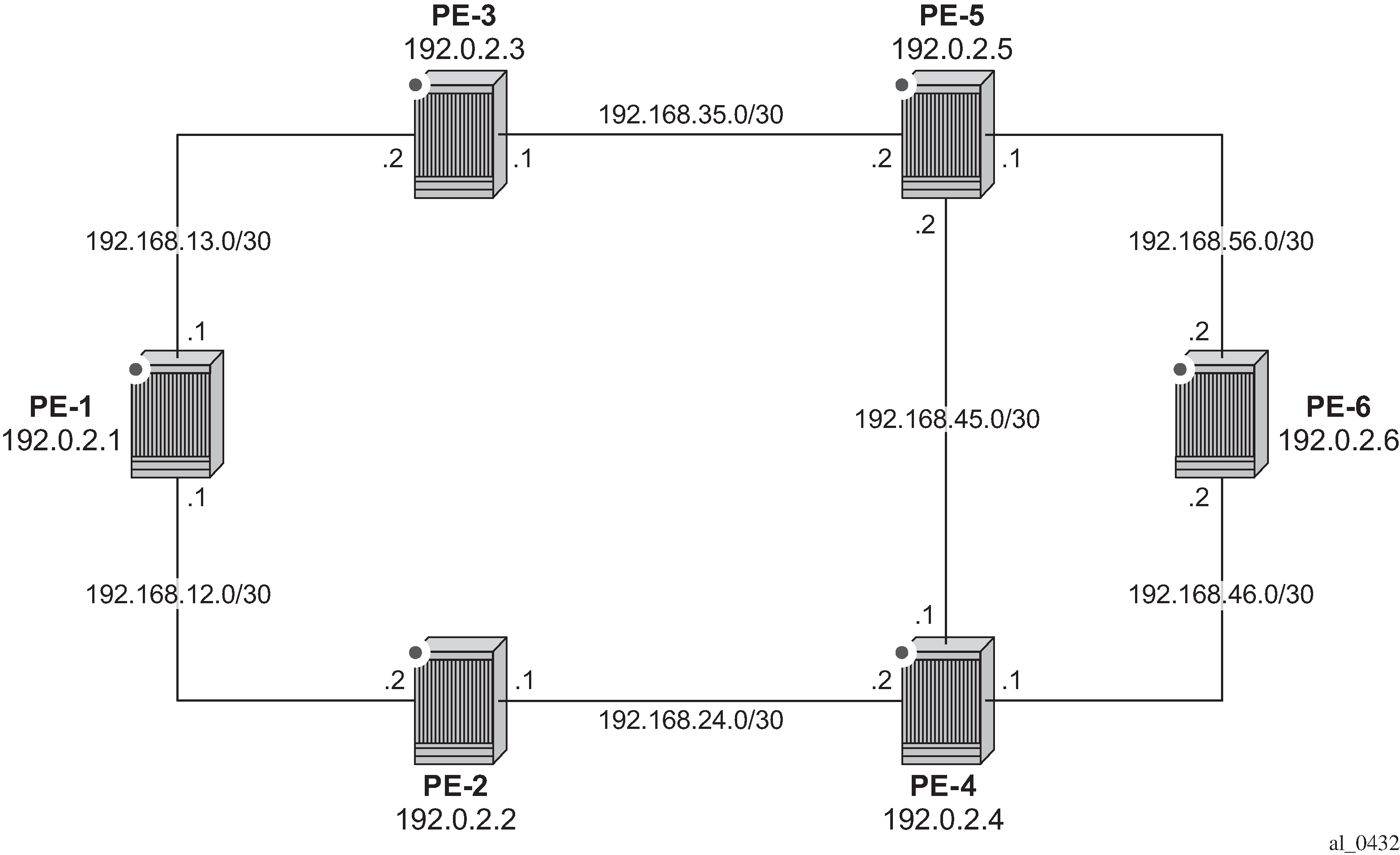
The example topology is shown in Example Topology. All routers participate in a single IS-IS Level 2 area that has traffic engineering enabled. Multi-Protocol Label Switching (MPLS) and RSVP are enabled on every interface, but no LSPs are initially provisioned. All routers are Border Gateway Protocol (BGP) speakers and form part of Autonomous System (AS) 64496. PE-5 is a Route Reflector and the remaining routers are IBGP clients for the IPv4, VPN-IPv4, and L2-VPN address families. The objective of this example is to demonstrate how to automatically create transport LSPs using RSVP or LDP over RSVP, and then create services that utilize those LSPs. The exchange of BGP routes is needed for those services.
Automatic Creation of an RSVP-TE LSP Mesh
To start the process of automatically creating an RSVP-TE LSP mesh, the user must create a route policy referencing a prefix-list. This prefix-list contains the system addresses of all nodes that are required to be in the mesh, and can be entered as a series of /32 addresses, or simply as a range as follows. This range encompasses all of the system addresses of the nodes in the example topology because the requirement is to make a full mesh.
configure
    router
        policy-options
            begin
             prefix-list "System-Addresses"
                 prefix 192.0.2.0/24 prefix-length-range 32-32
             exit
             policy-statement "Remote-PEs-policy"
                 entry 10
                     from
                         prefix-list "System-Addresses"
                     exit
                     action accept
                     exit
                 exit
             exit
            commit
            exit all
After the route policy is created, the user must create an LSP template containing the common parameters which are used to establish all point-to-point LSPs within the mesh. For an RSVP-TE LSP mesh, the lsp-template must be configured with the creation-time attribute mesh-p2p. Upon creation of the template, CSPF is automatically enabled (and cannot be disabled), and the template must reference a default-path before it can be placed in a no shutdown state. In the example contained in the following output, the template refers to a path named ‟loose-path” that has no strict or loose hops defined, meaning the system will dynamically calculate the path while considering other specified constraints. The LSP template in this output also stipulates fast-reroute facility bypass protection. The default behavior is no node-protect, so this configuration requests link protection only. FRR one-to-one protection is not supported for automatically created RSVP-TE LSPs; so facility bypass is the only form of protection supported. Finally, the template is placed in a no shutdown state.
Next, the user must associate the LSP template with the previously defined route policy, and this is accomplished using the auto-lsp lsp-template command. In this example, the LSP template ‟Full-Mesh-template” is associated with the policy-statement ‟Remote-PEs-policy” that in turn references a prefix-list containing all system addresses in the example topology. Up to five policies can be associated with an LSP template at the same time. If a policy associated with an LSP template is modified in order to add or remove prefixes, the system immediately re-evaluates the policy and the prefix-list to determine if one or more LSPs need to be established, or one or more LSPs need to be torn down.
configure
    router
        mpls
            path "loose-path"
                no shutdown
            exit
            lsp-template "Full-Mesh-template" mesh-p2p
                default-path "loose-path"
                path-computation-method local-cspf
                fast-reroute facility
                exit
                no shutdown
            exit
            auto-lsp lsp-template "Full-Mesh-template" policy "Remote-PEs-policy"
            no shutdown
        exit all
When the auto-lsp lsp-template command is entered, the system commences the process of establishing the point-to-point LSPs. The prefixes defined in the prefix list are checked, and if a prefix corresponds to a router ID that is present in the Traffic Engineering Database (TED), the system instantiates a CSPF computed primary path to that prefix using the parameters specified in the LSP template. With the previously defined configuration applied on PE-6, the existence of point-to-point RSVP LSPs to every node in the example topology can be verified as shown in the following output. The LSP name is automatically constructed as TemplateName-DestIPv4Address-TunnelId. The LSP name signaled in the Session Attribute object concatenates the LSP name with the path name (for example Full-Mesh-template-192.0.2.1-61441::loose-path).
*A:PE-6# show router mpls lsp

===============================================================================
MPLS LSPs (Originating)
===============================================================================
LSP Name                                            Tun     Fastfail  Adm  Opr
  To                                                Id      Config
-------------------------------------------------------------------------------
Full-Mesh-template-192.0.2.1-61441                  61441   Yes       Up   Up
  192.0.2.1
Full-Mesh-template-192.0.2.2-61442                  61442   Yes       Up   Up
  192.0.2.2
Full-Mesh-template-192.0.2.3-61443                  61443   Yes       Up   Up
  192.0.2.3
Full-Mesh-template-192.0.2.4-61444                  61444   Yes       Up   Up
  192.0.2.4
Full-Mesh-template-192.0.2.5-61445                  61445   Yes       Up   Up
  192.0.2.5
-------------------------------------------------------------------------------
LSPs : 5
===============================================================================
The LSP template requests FRR link protection. On PE-6, this protection can be verified by querying each primary LSP. In the following output, the primary LSP to PE-1 (Full-Mesh-template-192.0.2.1-61441) is signaled through PE-5 (192.0.2.5) and PE-3 (192.0.2.3), and the presence of the @ indicator after each hop denotes that link protection is available to the primary path.
*A:PE-6# show router mpls lsp path "Full-Mesh-template-192.0.2.1-61441" detail | match expression "LSP Name|Actual Hops" post-lines 4
LSP Name    : Full-Mesh-template-192.0.2.1-61441
From             : 192.0.2.6
To               : 192.0.2.1
Admin State      : Up                      Oper State        : Up
Path Name   : loose-path
Actual Hops      :
    192.168.56.2(192.0.2.6) @                    Record Label        : N/A
 -> 192.168.56.1(192.0.2.5) @                    Record Label        : 524269
 -> 192.168.35.1(192.0.2.3) @                    Record Label        : 524272
 -> 192.168.13.1(192.0.2.1)                      Record Label        : 524273
Finally, it can be verified that the signaled LSPs are placed in the tunnel table and made available to the tunnel table manager so they can be used by applications and services.
*A:PE-6# show router tunnel-table

===============================================================================
IPv4 Tunnel Table (Router: Base)
===============================================================================
Destination           Owner     Encap TunnelId  Pref   Nexthop        Metric
   Color
-------------------------------------------------------------------------------
192.0.2.1/32 [B]      rsvp      MPLS  61441     7      192.168.56.1   30
192.0.2.2/32 [B]      rsvp      MPLS  61442     7      192.168.46.1   20
192.0.2.3/32 [B]      rsvp      MPLS  61443     7      192.168.56.1   20
192.0.2.4/32 [B]      rsvp      MPLS  61444     7      192.168.46.1   10
192.0.2.5/32 [B]      rsvp      MPLS  61445     7      192.168.56.1   10
-------------------------------------------------------------------------------
Flags: B = BGP or MPLS backup hop available
       L = Loop-Free Alternate (LFA) hop available
       E = Inactive best-external BGP route
       k = RIB-API or Forwarding Policy backup hop
===============================================================================
When the LSP template is in use and LSPs are instantiated, it is necessary to place the template into a shutdown state to change any parameters that cannot be handled as a Make-Before-Break (MBB). This essentially includes all LSP parameters with the exception of bandwidth and FRR without node-protection. Modification of any other parameters requires a shutdown of the LSP template and a re-signal of the LSP once the LSP template is placed in the no shutdown state again. MBB is supported for timer-based and manual re-signaling of the automatically created LSPs.
Service and Application Verification
With the RSVP-TE LSP mesh in place, it is now possible to create services and applications to utilize those LSPs. These applications and services include Layer 2 and Layer 3 VPNs, resolution of BGP labeled routes and resolution of BGP, IGP, and static routes. However, the automatically created LSPs are not available for explicit binding in a statically provisioned Service Distribution Point (SDP).
IGP Shortcuts
IGP Shortcuts with RSVP-TE Auto-Mesh demonstrates the use of IGP shortcuts. Prefix 172.16.32.0/20 is advertised to PE-1 from an external peer in AS 64510, which PE-1 subsequently advertises into IBGP, imposing Next-Hop-Self in the process. For more details on IGP shortcuts, see the IGP Shortcuts chapter.
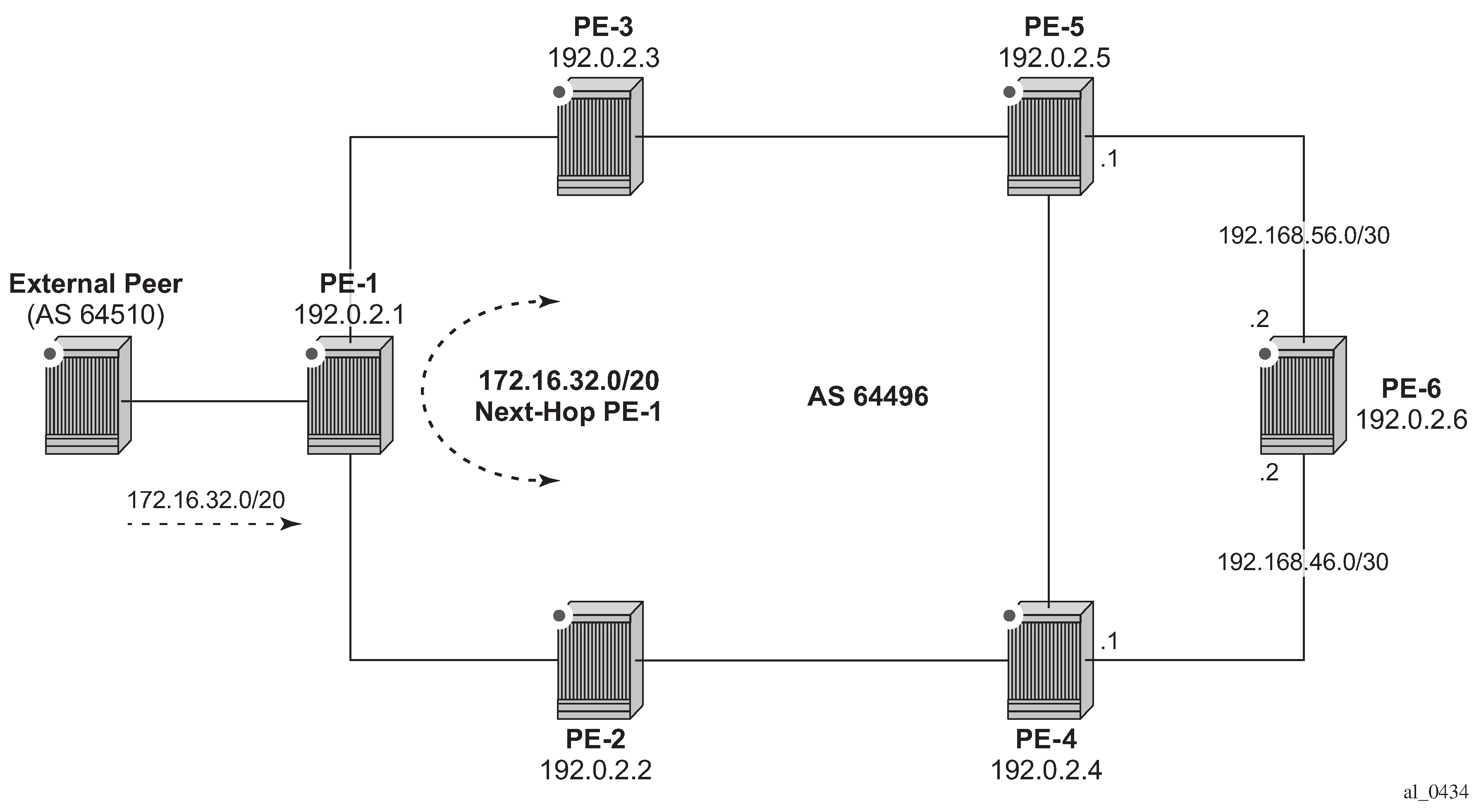
The objective is for PE-6 to use the automatically created LSP to PE-1 as an IGP shortcut (typically implemented in order to maintain a ‟BGP-free” core). IGP shortcuts for BGP are enabled under the main bgp context using the command next-hop-resolution shortcut-tunnel with options for rsvp, ldp, or bgp. Because the example topology only has (automatically created) RSVP-TE LSPs, this option is selected. Besides rsvp, ldp, and bgp, there are other options, but these are beyond the scope of this chapter.
configure router bgp next-hop-resolution shortcut-tunnel family ?
  - family <family>

 <family>             : ipv4|ipv6

 [no] allow-flex-alg* - Allow/Disallow Flex Algo Fallback
 [no] disallow-igp    - Allow/Disallow IGP shortcuts
 [no] enforce-strict* - Enable/Disable Use of admin-tags for resolving routes for the Next-hop families
      resolution      - Configure resolution state of BGP unlabeled routes to tunnels
      resolution-fil* + Configure specific tunnels to be used for resolving BGP unlabeled routes
configure router bgp next-hop-resolution shortcut-tunnel family ipv4 resolution-filter ?
  - resolution-filter

 [no] bgp             - Use BGP tunnelling for next hop resolution
 [no] ldp             - Use LDP tunnelling for next hop resolution
 [no] mpls-fwd-policy - Use MPLS Forwarding Policy for next hop resolution
 [no] rib-api         - Use RIB-API for next-hop resolution
 [no] rsvp            - Use RSVP tunnelling for next hop resolution
 [no] sr-isis         - Use sr-isis for next hop resolution
 [no] sr-ospf         - Use sr-ospf for next hop resolution
 [no] sr-ospf3        - Use sr-ospf3 for next hop resolution
 [no] sr-policy       - Use sr-policy for next hop resolution
 [no] sr-te           - Use sr-te for next hop resolution
*A:PE-6# configure
    router
        bgp
            next-hop-resolution
                shortcut-tunnel
                    family ipv4
                        resolution-filter
                            rsvp
                        exit
                        resolution filter
                    exit
                exit
            exit
            exit all
When the shortcuts are enabled, the route-table (and FIB) can be validated to ensure that the programmed next hop is the advertising BGP speaker (as opposed to the IGP next hop), and that traffic is tunneled to that next hop through an RSVP LSP. In this case, the RSVP LSP is the LSP with tunnel ID 61441, which is the LSP to PE-1.
*A:PE-6# show router route-table 172.16.32.0/20

===============================================================================
Route Table (Router: Base)
===============================================================================
Dest Prefix[Flags]                            Type    Proto     Age        Pref
      Next Hop[Interface Name]                                    Metric
-------------------------------------------------------------------------------
172.16.32.0/20                                Remote  BGP       00h00m55s  170
       192.0.2.1 (tunneled:RSVP:61441)                              30
-------------------------------------------------------------------------------
No. of Routes: 1
Flags: n = Number of times nexthop is repeated
       B = BGP backup route available
       L = LFA nexthop available
       S = Sticky ECMP requested
===============================================================================
Layer 3 VPN
Layer 3 VPNs can utilize the automatically created LSPs by using the auto-bind-tunnel feature configured with the rsvp option (possibly in combination with LDP). The option to include both RSVP and LDP allows the system to use an RSVP LSP if one exists, and if not, to revert to an LDP-based LSP. A Virtual Private Routed Network (VPRN) is configured on PE-1 and PE-6. PE-1 is configured with a loopback address of 172.16.1.1/24 and advertises the VPN-IPv4 prefix 172.16.1.0/24 into IBGP, while PE-6 is configured with a loopback address of 172.16.6.1/24 and advertises the VPN-IPv4 prefix 172.16.6.0/24 into IBGP. The VPRN configuration on PE-6 is as follows. The only difference on PE-1 is the IP address assigned to the loopback interface.
*A:PE-6#
configure
    service
        vprn 1 name "VPRN 1" customer 1 create
            route-distinguisher 64496:1
            auto-bind-tunnel
                resolution-filter
                    ldp
                    rsvp
                exit
                resolution filter
            exit
            vrf-target target:64496:1
            interface "loopback" create
                address 172.16.6.1/24
                loopback
            exit
            no shutdown
        exit
        exit all
Before a VPN-IPv4 prefix is considered valid, the receiving SR OS PE router must be able to resolve the BGP next hop to an LSP in the tunnel table (if not, the prefix is held in Routing Information Base RIB-IN and flagged as invalid). On PE-6, it is possible to verify that the VPN-IPv4 prefix 172.16.1.0/24 received from PE-1 is correctly resolved by looking at the VPRN-specific route table. In the following output, the VPN-IPv4 prefix 172.16.1.0/24 with a next hop of PE-1 (192.0.2.1) is correctly resolved to an RSVP LSP with a tunnel ID of 61441.
*A:PE-6# show router 1 route-table 172.16.1.0/24

===============================================================================
Route Table (Service: 1)
===============================================================================
Dest Prefix[Flags]                            Type    Proto     Age        Pref
      Next Hop[Interface Name]                                    Metric
-------------------------------------------------------------------------------
172.16.1.0/24                                 Remote  BGP VPN   00h00m32s  170
       192.0.2.1 (tunneled:RSVP:61441)                              30
-------------------------------------------------------------------------------
No. of Routes: 1
Flags: n = Number of times nexthop is repeated
       B = BGP backup route available
       L = LFA nexthop available
       S = Sticky ECMP requested
===============================================================================
Layer 2 VPN
As previously described, automatically created RSVP LSPs cannot be referenced by statically provisioned SDPs. Without the ability for SDPs to explicitly reference automatically created RSVP LSPs, there is little value in manually defining SDPs within Layer 2 service constructs (there is little point in referring to an SDP that cannot bind to the underlying RSVP mesh). So, in order to deliver Layer 2 services, there is a requirement to adopt a model within the service construct that permits automatic creation of SDP bindings, and this is achieved using a pseudowire template dictating the characteristics of the SDP. The secondary effect of using pseudowire templates to dynamically create SDPs is that these automatically created SDPs can currently only use LDP or BGP as a transport tunnel, not RSVP. The solution is to enable LDP over RSVP.
This can be implemented using static provisioning of peers as shown in the next output, or it can be done using automatic creation of T-LDP sessions. Regardless of the method, a reciprocal configuration must exist at both peer endpoints. The static per-peer configuration is applied in the targeted-session context specifying the remote peer system IP address, and the keyword tunneling, which enables tunneling of LDP FECs over RSVP LSPs with a far-end address matching that of the T-LDP peer. At a global level, the prefer-tunnel-in-tunnel command is shown, but is only required when a next hop router advertises a FEC over link-level LDP and T-LDP. In this case, by default, the system would prefer the link-level LDP tunnel, so the prefer-tunnel-in-tunnel instructs the system to prefer an LDP over RSVP tunnel if it is available. Although link-layer LDP is not present in the example topology, the command is included because the presence of link-layer LDP is common.
configure
    router
        ldp
            prefer-tunnel-in-tunnel
            targeted-session
                peer 192.0.2.1
                    tunneling
                    exit
                exit
            exit
            no shutdown
        exit all
The following output provides an example demonstrating the automatic creation of T-LDP sessions. No explicit reference is made to specific peers, but rather a peer-template is configured containing the parameters which apply to all T-LDP sessions spawned by this template. In this example, only the tunneling command is required. A peer-template-map is then used to create a mapping between the peer-template (TLDP-Mesh-template) and a policy defining the IP addresses of remote nodes to which T-LDP sessions should be established. In this example, the policy ‟Remote-PEs-policy” is the same policy previously used by the auto-created RSVP LSP mesh.
configure
    router
        ldp
            prefer-tunnel-in-tunnel
            interface-parameters
            exit
            targeted-session
                peer-template "TLDP-Mesh-template"
                    tunneling
                exit
                peer-template-map peer-template "TLDP-Mesh-template" policy "Remote-PEs-policy"
            exit
            no shutdown
        exit all
Regardless of whether T-LDP sessions are explicitly provisioned, or dynamically created using a peer-template, the result is that a targeted LDP session is established which can be used for advertising address and service FECs, and which is capable of tunneling LDP over RSVP.
*A:PE-6# show router ldp targ-peer 192.0.2.1 detail

===============================================================================
LDP IPv4 Targeted Peers
===============================================================================
-------------------------------------------------------------------------------
192.0.2.1
-------------------------------------------------------------------------------
Admin State        : Up              Oper State           : Up
Last Oper Chg      : 0d 00:01:10
Hold Time          : 45              Hello Factor         : 3
Oper Hold Time     : 45
Hello Reduction    : Disabled        Hello Reduction Fctr : 3
Keepalive Timeout  : 40              Keepalive Factor     : 4
Active Adjacencies : 0               Last Modified        : Never
Auto Created       : Yes
Creator            : template        Name        : TLDP-Mesh-template
Tunneling          : Enabled
Lsp Name           : None
Mcast-Tunneling    : Disabled
Lsp Name           : None
Local LSR          : None            32-BitLocalLsr       : Disabled
Local-LSR ID adv.  : Disabled
Community          :
BFD Status         : Disabled
===============================================================================
No. of IPv4 Targeted Peers: 1
===============================================================================
To create VPLS services using dynamically-created SDPs, BGP Auto-Discovery (BGP-AD) must be used together with LDP (or BGP) pseudowire signaling, for more details see the LDP VPLS Using BGP-Auto Discovery chapter.
In the following output, PE-6 uses BGP-AD and LDP signaling. The same configuration is applied on PE-1. The vpls-id is configured in the bgp-ad context. The vpls-id is a network-wide identifier assigned to all VPLS Switch Instances (VSIs) belonging to the same VPLS, and is carried in VPLS Network Layer Reachability Information (NLRI) as an extended community attribute. A second parameter used for BGP-AD and carried in the VPLS NLRI is the VSI-ID, which uniquely identifies each VSI. The VSI-ID is automatically derived from the global ASN, the VPLS service ID, and the system IP address. To automatically create SDPs, the bgp context of the VPLS service refers to a pw-template defining the parameters of the pseudowire. In this example, the use of the hash (entropy) label is enabled in the pseudowire template, and a split-horizon-group, SHG, is applied.
configure
    service
        pw-template 2 name "PW2-template" create
            hash-label
            split-horizon-group "SHG"
            exit
        exit
        vpls 2 name "VPLS 2" customer 1 create
            bgp
                pw-template-binding 2
                exit
            exit
            bgp-ad
                vpls-id 64496:2
                no shutdown
            exit
            sap 1/1/4:2 create
            exit
            no shutdown
        exit
        exit all
The following output shows the BGP and BGP-AD operational parameters, and shows that an SDP of type BgpAd (32767:4294967295) has been automatically created for vpls 2. Both the SDP and the SAP are operationally up.
*A:PE-6# show service id 2 bgp

===============================================================================
BGP Information
===============================================================================
Bgp Instance         : 1
Vsi-Import           : None
Vsi-Export           : None
Route Dist           : None
Oper Route Dist      : 64496:2
Oper RD Type         : derivedVpls
Rte-Target Import    : None                 Rte-Target Export: None
Oper RT Imp Origin   : derivedVpls          Oper RT Import   : 64496:2
Oper RT Exp Origin   : derivedVpls          Oper RT Export   : 64496:2

PW-Template Id       : 2                    PW-Template SHG  : None
Oper Group           : None
Mon Oper Group       : None
BFD Template         : None
BFD-Enabled          : no                   BFD-Encap        : ipv4
Import Rte-Tgt       : None
-------------------------------------------------------------------------------
===============================================================================
*A:PE-6# show service id 2 bgp-ad

-------------------------------------------------------------------------------
BGP Auto-discovery Information
-------------------------------------------------------------------------------
Admin State       : Up
Vpls Id           : 64496:2
Prefix            : 192.0.2.6
-------------------------------------------------------------------------------
*A:PE-6# show service id 2 base | match "Service Access" post-lines 10
Service Access & Destination Points
-------------------------------------------------------------------------------
Identifier                               Type         AdmMTU  OprMTU  Adm  Opr
-------------------------------------------------------------------------------
sap:1/1/4:2                              q-tag        1518    1518    Up   Up
sdp:32767:4294967295 SB(192.0.2.1)       BgpAd        0       0       Up   Up
===============================================================================
* indicates that the corresponding row element may have been truncated.
To create Epipe services using dynamically created SDPs, two options exist. Either LDP FEC 129 signaling can be used, which in turn dictates the presence of pseudowire routing information, or BGP-VPWS based signaling can be used, for more details, see the BGP Virtual Private Wire Services chapter. This example illustrates the use of BGP VPWS, but in either case, only single-segment pseudowires are supported. The following output shows the configuration requirements for a basic BGP-based Epipe service on PE-6. Once again, a pw-template is used to define the characteristics of the pseudowire, and this template is referenced in the bgp context of the Epipe service. The bgp context is also where the route-distinguisher and route-target values are configured, which are carried in the VPWS NLRI and extended communities respectively. The ve-name, ve-id, and remote-ve-name are all configured in the bgp-vpws context. The ve-id is carried in the VPWS NLRI, and when a PE router receives a VPWS NLRI to try to establish an Epipe service, the ve-id from the NLRI is validated against the ve-id configured in the remote-ve-name. These must match before the Epipe becomes operational.
*A:PE-6#
configure
    service
        pw-template 3 name "PW3-template" create
            hash-label
        exit
        epipe 3 name "Epipe 3" customer 1 create
            bgp
                route-distinguisher 64496:3
                route-target export target:64496:3 import target:64496:3
                pw-template-binding 3
                exit
            exit
            bgp-vpws
                ve-name "PE-6"
                    ve-id 6
                exit
                remote-ve-name "PE-1"
                    ve-id 1
                exit
                no shutdown
            exit
            sap 1/1/4:3 create
            exit
            no shutdown
        exit all
The basic service information is truncated to show only the relevant information in order to verify that the service is operational. SDP (32766:4294967294) has been automatically created and is of type BgpVpws. Both the SDP and the SAP are operationally up.
*A:PE-6# show service id 3 base | match "Service Access" post-lines 10
Service Access & Destination Points
-------------------------------------------------------------------------------
Identifier                               Type         AdmMTU  OprMTU  Adm  Opr
-------------------------------------------------------------------------------
sap:1/1/4:3                              q-tag        1518    1518    Up   Up
sdp:32766:4294967294 SB(192.0.2.1)       BgpVpws      0       0       Up   Up
===============================================================================
Automatic Creation of RSVP Single-Hop LSPs
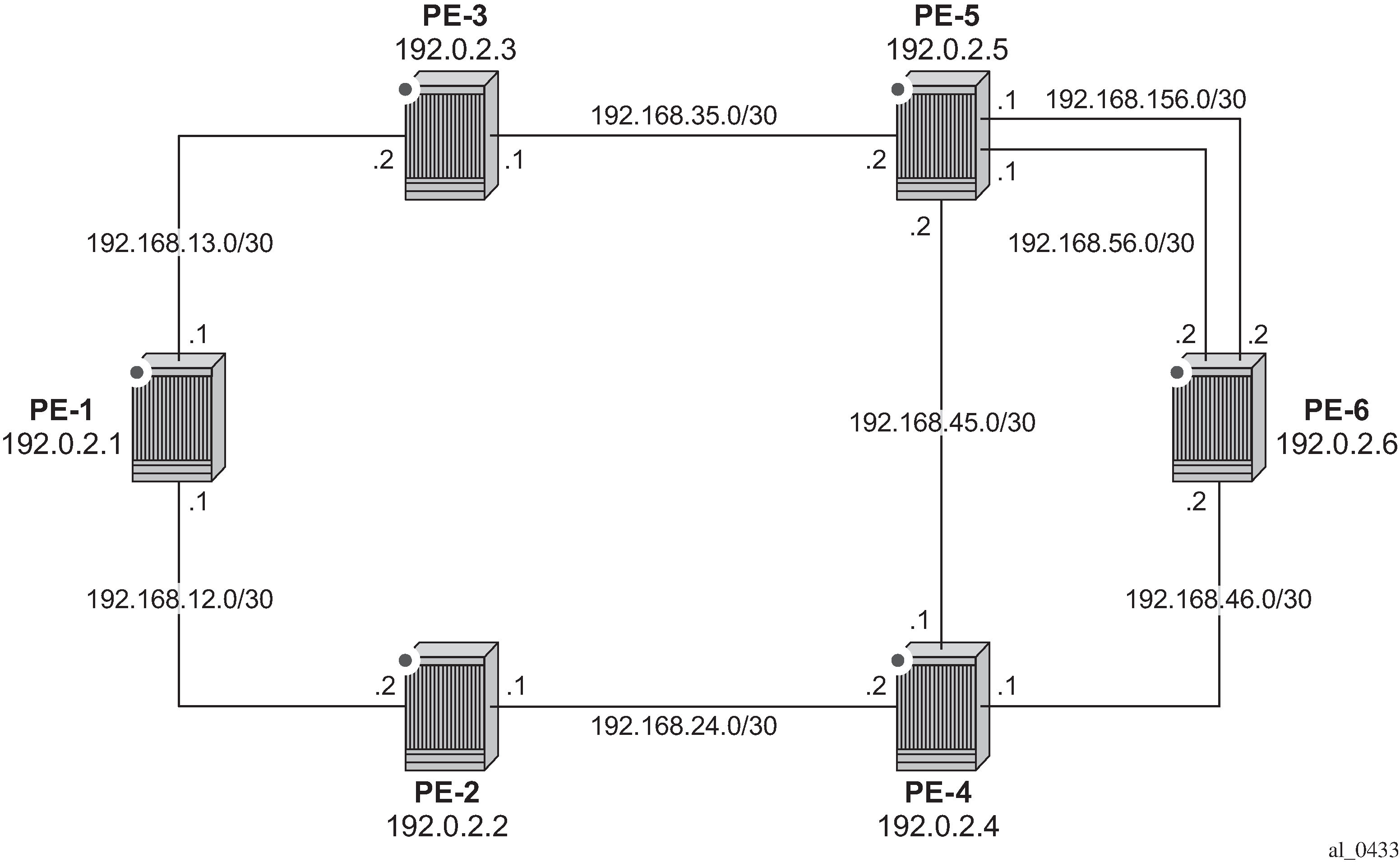
As previously discussed, the purpose of a single-hop LSP mesh is to allow for ECMP load balancing of traffic using LDP over RSVP. ECMP load balancing could be implemented using LDP over a partial or full mesh of RSVP-TE LSPs, but the use of single-hop LSPs additionally allows for load balancing across a number of parallel RSVP LSPs between nodes. To illustrate ECMP load balancing over multiple parallel RSVP LSPs, the example topology of Example Topology is modified to include a parallel link between PE-6 and PE-5 as shown in Example Topology for Single-Hop LDP over RSVP with ECMP. In addition, all routers are enabled for ECMP=2, as follows.
configure router ecmp 2
Unlike the automatically created RSVP-TE LSP mesh previously described, the automatically created single-hop RSVP-TE LSPs have no requirement for a prefix-list to be referenced containing the prefixes of the remote nodes that form part of the mesh. In the case of automatically created single-hop LSPs, the TE database keeps track of each TE link which comes up to a directly connected IGP neighbor. The system then establishes a single-hop LSP with a destination address matching the router ID of the neighbor and with a strict hop consisting of the address of the interface used by the TE link.
The first requirement is to create an LSP template containing the common parameters used to establish each single-hop LSP. For a single-hop LSP mesh, the lsp-template must be configured with the creation-time attribute one-hop-p2p. Upon creation of the template, cspf is automatically enabled (and cannot be disabled), and the hop-limit is set to a value of 2. The hop limit defines the number of nodes the LSP may traverse, and, because these are single-hop LSPs to adjacent neighbors, a limit of 2 is sufficient. The template must also reference a default-path before it can be placed in the no shutdown state. The following example references a path named ‟loose-path” that has no strict or loose hops defined. When the RSVP PATH message is actually generated to create the one-hop LSP, it contains one strict-hop to the interface address of the neighbor; and as destination the system address of the adjacent node.
The next requirement is to trigger the creation of single-hop LSPs, and this is achieved using the auto-lsp lsp-template command. In this example, the LSP template ‟Single-Hop-template” is referenced, and the command is completed with the keyword one-hop to indicate the creation of single-hop LSPs. Unlike an RSVP-TE mesh, there is no requirement to reference a route policy. In the example, the auto-lsp with LSP template ‟Full-Mesh-template” is removed on all PEs.
configure router mpls no auto-lsp lsp-template "Full-Mesh-template"
The following one-hop LSP template is created on all nodes:
configure
    router
        mpls
            path "loose-path"
                no shutdown
            exit
            lsp-template "Single-Hop-template" one-hop-p2p
                default-path "loose-path"
                path-computation-method local-cspf
                hop-limit 2
                no shutdown
            exit
            auto-lsp lsp-template "Single-Hop-template" one-hop
            no shutdown
            exit all
Once the auto-lsp lsp-template command is entered, the system starts the process of establishing the single-hop LSPs. A check is made of the TE database for every TE link to a directly connected IGP neighbor, and a single-hop LSP is established across each TE link. The following output is taken from PE-6 and shows the automatically created single-hop LSPs. The LSP names are automatically constructed as TemplateName-DestIPv4Address-TunnelId. The LSP name signaled in the session attribute object concatenates the LSP name with the path name (for example Single-Hop-template-192.0.2.4-61449::loose-path). Recall from Example Topology for Single-Hop LDP over RSVP with ECMP that PE-6 has a single TE-enabled link to PE-4, and two TE-enabled links to PE-5, so with ECMP=2, there is one LSP to PE-4 (192.0.2.4) and two LSPs to PE-5 (192.0.2.5). However, if ECMP=1, only one single-hop LSP would be signaled to PE-5.
*A:PE-6# show router mpls lsp

===============================================================================
MPLS LSPs (Originating)
===============================================================================
LSP Name                                            Tun     Fastfail  Adm  Opr
  To                                                Id      Config
-------------------------------------------------------------------------------
Single-Hop-template-192.0.2.4-61448                 61448   No        Up   Up
  192.0.2.4
Single-Hop-template-192.0.2.5-61449                 61449   No        Up   Up
  192.0.2.5
Single-Hop-template-192.0.2.5-61450                 61450   No        Up   Up
  192.0.2.5
-------------------------------------------------------------------------------
LSPs : 3
===============================================================================
The purpose of single-hop LSPs is to enable ECMP load balancing using LDP over RSVP, so there is a requirement to configure T-LDP sessions between RSVP LSP endpoints. This can be implemented using static peer provisioning, or it can be done using automatic creation of T-LDP sessions, both of which have been previously described and they are therefore not repeated. In this example, the automatic creation of T-LDP sessions approach is used, and T-LDP sessions are created to adjacent neighbors that are capable of tunneling inside RSVP.
*A:PE-6# show router ldp session ipv4

==============================================================================
LDP IPv4 Sessions
==============================================================================
Peer LDP Id         Adj Type  State         Msg Sent  Msg Recv  Up Time
------------------------------------------------------------------------------
192.0.2.4:0         Targeted  Established   40        41        0d 00:02:41
192.0.2.5:0         Targeted  Established   40        41        0d 00:02:37
------------------------------------------------------------------------------
No. of IPv4 Sessions: 2
==============================================================================
To validate the ECMP load balancing capability, PE-5 is configured to advertise prefix 172.16.5.0/24 to PE-6. In turn, PE-6 is configured for ibgp-multipath to enable load balancing over IGP links to the BGP next hop address, next-hop-resolution shortcut-tunnel resolution-filter ldp to enable tunneling of traffic destined toward the BGP next hop in MPLS, and ecmp 2. For additional information on BGP multipath, see the BGP Multipath chapter.
configure
    router
        bgp
            ibgp-multipath
            next-hop-resolution
                shortcut-tunnel
                    family ipv4
                        resolution-filter
                            ldp
                            no rsvp
                        exit
                        resolution filter
                    exit
                exit
            exit
            exit all
The prefix 172.16.5.0/24 advertised by PE-5 is learned on PE-6 and installed in the RIB/FIB with PE-5’s system address (192.0.2.5) as next hop.
*A:PE-6# show router bgp routes 172.16.5.0/24
===============================================================================
 BGP Router ID:192.0.2.6        AS:64496       Local AS:64496
===============================================================================
 Legend -
 Status codes  : u - used, s - suppressed, h - history, d - decayed, * - valid
                 l - leaked, x - stale, > - best, b - backup, p - purge
 Origin codes  : i - IGP, e - EGP, ? - incomplete

===============================================================================
BGP IPv4 Routes
===============================================================================
Flag  Network                                            LocalPref   MED
      Nexthop (Router)                                   Path-Id     IGP Cost
      As-Path                                                        Label
-------------------------------------------------------------------------------
u*>i  172.16.5.0/24                                      100         None
      192.0.2.5                                          None        10
      No As-Path                                                     -
-------------------------------------------------------------------------------
Routes : 1
===============================================================================
Checking the FIB for the next hop address 192.0.2.5, it can be verified that both links are installed as next hop addresses, meaning that ECMP load balancing is active.
*A:PE-6# show router fib 1 192.0.2.5/32

===============================================================================
FIB Display
===============================================================================
Prefix [Flags]                                              Protocol
  NextHop
-------------------------------------------------------------------------------
192.0.2.5/32                                                ISIS
  192.168.56.1 (int-PE-6-PE-5)
  192.168.156.1 (int-PE-6-PE-5-2nd)
-------------------------------------------------------------------------------
Total Entries : 1
-------------------------------------------------------------------------------
===============================================================================
Conclusion
Automatic creation of RSVP-TE LSPs provides a good solution for reducing the amount of provisioning activity required when configuring RSVP LSPs. However, there are some constraints with regard to the way that services are deployed on top of those LSPs. SDPs cannot explicitly reference automatically-created RSVP LSPs, which means that automatically created SDPs need to be used for Layer 2 services. In turn, automatically-created SDPs can only use LDP or BGP as a transport tunnel (not RSVP), so, in order to use the automatically created RSVP mesh, LDP over RSVP must be used. These caveats need to be fully understood before considering deployment of automatically created RSVP-TE LSPs.