Class-Based Forwarding
This chapter provides information about class-based forwarding
Topics in this chapter include:
Applicability
This chapter is applicable to SR OS routers and was initially written for Release 13.0.R7. The CLI in this edition corresponds to Release 14.0.R1.
Before SR OS 13.0.R6, class-based forwarding (CBF) was only applicable to resource reservation protocol (RSVP) label switched paths (LSPs) in multi-LSP service distribution points (SDPs) used by services. In Release 13.0.R6, CBF of label distribution protocol (LDP) prefix packets over interior gateway protocol (IGP) shortcuts was introduced. Both implementations are described in this chapter.
Overview
In large networks, services are typically required from any PE to any other PE, and can traverse multiple domains. Within a service, different traffic classes can coexist, each with different requirements for latency and jitter.
With CBF, packets with different forwarding classes (FCs) can be forwarded on different LSPs. When equal-cost multipath (ECMP) routing without CBF is used, packets are distributed over the whole set of LSPs, without any distinction for the FC. CBF is based on FC, not on the traffic being in-profile or out-of-profile, and is a local decision, which makes it easier for interoperability.
This feature may be useful when certain links have less bandwidth and should only be used for high priority traffic. A service provider might decide to send real-time traffic over a shorter path with less bandwidth, while the bulk of the traffic takes a longer path with more bandwidth.
Configuration
The initial implementation for CBF was based on RSVP LSPs. This is described first, followed by CBF of LDP prefix packets over IGP shortcuts.
CBF over RSVP LSPs
CBF over RSVP LSPs allows a service packet to be forwarded over a specific RSVP LSP, part of an SDP, based on its service ingress determined FC, typically controlled by a default or operator-defined sap-ingress policy. A default LSP is configured for all traffic that does not match the FCs that are explicitly configured in the SDP. CBF over RSVP LSPs is also used to forward a received packet that has been classified at the ingress service access point (SAP) into an FC, if the LSP that supports its FC is not available.
CBF can also be enabled on static LSPs in the same way, but that scenario is not common.
A multicast LSP is configured for broadcast, unknown, and multicast (BUM) traffic. When no multicast LSP is defined, BUM traffic uses the default LSP. Because there are multiple LSPs per SDP, CBF over RSVP LSPs increases the number of RSVP sessions.
The test topology is shown in Test Topology for CBF on RSVP LSPs. This topology will be extended in a subsequent use case.
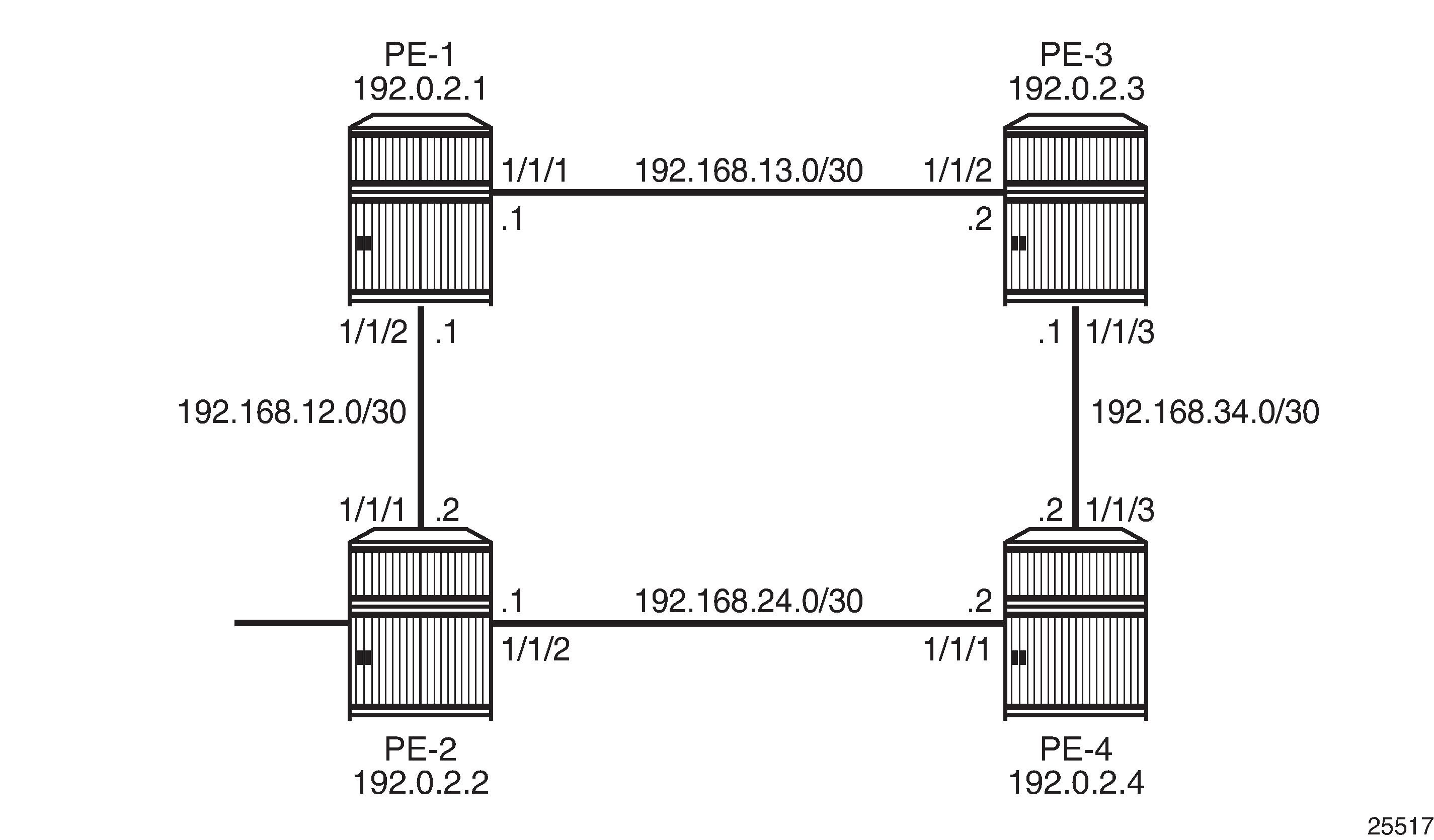
Initial Configuration
All nodes have the following initial configuration:
Cards, media dependent adapters (MDAs), ports
Router interfaces
IGP open shortest path first (OSPF) or intermediate system to intermediate system (IS-IS)
Multiprotocol label switching (MPLS) enabled on all router interfaces
RSVP enabled
RSVP LSPs
As an example, the configuration on PE-1 is shown. The configuration for PE-2 is similar.
*A:PE-1# configure router
        interface "int-PE-1-P-3"
            address 192.168.13.1/30
            port 1/1/1
        exit
        interface "int-PE-1-PE-2"
            address 192.168.12.1/30
            port 1/1/2
        exit
        interface "system"
            address 192.0.2.1/32
        exit
*A:PE-1# configure router
        ospf
            traffic-engineering
            area 0.0.0.0
                interface "system"
                exit
                interface "int-PE-1-PE-2"
                    interface-type point-to-point
                exit
                interface "int-PE-1-P-3"
                    interface-type point-to-point
                exit
            exit
        exit
*A:PE-1# configure router
        mpls
            interface "int-PE-1-PE-2"
            exit
            interface "int-PE-1-P-3"
            exit
            no shutdown
        exit
*A:PE-1# configure router rsvp no shutdown
The RSVP LSPs use paths with strict hops:
*A:PE-1# configure router
        mpls
            path "direct-PE-1-PE-2"
                hop 10 192.168.12.2 strict
                no shutdown
            exit
            path "indirect-PE-1-PE-2"
                hop 10 192.168.13.2 strict
                hop 20 192.168.34.2 strict
                hop 30 192.168.24.1 strict
                no shutdown
            exit
            lsp "LSP-PE-1-PE-2-EF"
                to 192.0.2.2
                primary "direct-PE-1-PE-2"
                exit
                no shutdown
            exit
            lsp "LSP-PE-1-PE-2-default"
                to 192.0.2.2
                primary "indirect-PE-1-PE-2"
                exit
                no shutdown
            exit
            no shutdown
        exit
The configured RSVP LSPs are shown in LSPs with Direct and Indirect Path toward PE-2.
Configure SDPs
In the initial configuration, the traffic is by default sent on LSP "LSP-PE-1-PE-2-default", except when the FC is expedited forwarding (EF). The traffic with FC EF is sent over LSP "LSP-PE-1-PE-2-EF". Both LSPs are assigned to SDP 122 on PE-1:
*A:PE-1# configure service
        sdp 122 mpls create
            description "SDP-PE-1-PE-2"
            far-end 192.0.2.2
            lsp "LSP-PE-1-PE-2-EF"
            lsp "LSP-PE-1-PE-2-default"
            path-mtu 1514
            class-forwarding default-lsp "LSP-PE-1-PE-2-default"
                fc "ef" lsp "LSP-PE-1-PE-2-EF"
                no shutdown
            exit
            no shutdown
        exit
A change in the CBF configuration may result in a change of forwarding behavior.
The configuration of SDP 212 from PE-2 to PE-1 is similar.
For the SDPs to get operational up, targeted-LDP (T-LDP) must be enabled on the PE nodes:
*A:PE-1# configure router ldp no shutdown
The state of the SDP can be verified as follows:
*A:PE-1# show service sdp
============================================================================
Services: Service Destination Points
============================================================================
SdpId  AdmMTU  OprMTU  Far End          Adm  Opr         Del     LSP   Sig
----------------------------------------------------------------------------
122    1514    1514    192.0.2.2        Up   Up          MPLS    R     TLDP
----------------------------------------------------------------------------
Number of SDPs : 1
----------------------------------------------------------------------------
Legend: R = RSVP, L = LDP, B = BGP, M = MPLS-TP, n/a = Not Applicable
        I = SR-ISIS, O = SR-OSPF, T = SR-TE
============================================================================
*A:PE-1#
Some Considerations
When CBF is enabled, a default LSP must be configured. An error is raised when class-forwarding is enabled without a default LSP:
*A:PE-1>config>service>sdp# class-forwarding
MINOR: CLI Default LSP must be specified.
Only one LSP can be configured as the default LSP in the sdp context. Configuring another LSP as the default LSP overwrites the originally configured LSP.
Only one LSP can be assigned to an FC in the sdp context. Configuring another LSP for an FC overwrites the originally configured LSP.
An LSP can be assigned to multiple FCs in the sdp context.
The default LSP can also be assigned to one or more FCs in the sdp context.
*A:PE-1>config>service# info
----------------------------------------------
        sdp 122 mpls create
            description "RSVP-SDP-PE-1-PE-2"
            far-end 192.0.2.2
            lsp "LSP-PE-1-PE-2-EF"
            lsp "LSP-PE-1-PE-2-default"
            path-mtu 1514
            keep-alive
                shutdown
            exit
            class-forwarding default-lsp "LSP-PE-1-PE-2-default"
                fc "af" lsp "LSP-PE-1-PE-2-default"
                fc "be" lsp "LSP-PE-1-PE-2-default"
                fc "ef" lsp "LSP-PE-1-PE-2-EF"
                multicast-lsp "LSP-PE-1-PE-2-default"
                no shutdown
            exit
            no shutdown
        exit
The SDP goes down when the default LSP goes down.
When CBF is configured on the LSP/LSP template as well as on the SDP, the configuration on the LSP/LSP template is ignored. Configuring CBF in the LSP/LSP template context is required in another use case: CBF of LDP Prefix Packets over IGP Shortcuts. This is described later in this chapter.
Configure Services for Traffic Verification
To verify that EF traffic is sent over the direct link while traffic with a different FC is sent over the longer path, two services are configured on PE-1 and PE-2.
To generate traffic, ping messages will be sent in virtual private routed network 1 (VPRN 1). The outgoing traffic is sent to virtual private LAN service 2 (VPLS 2) where the FC can be modified to EF if needed. VPLS 2 has the spoke SDP with the different LSPs and CBF. This is shown in CBF on RSVP LSPs - Services.
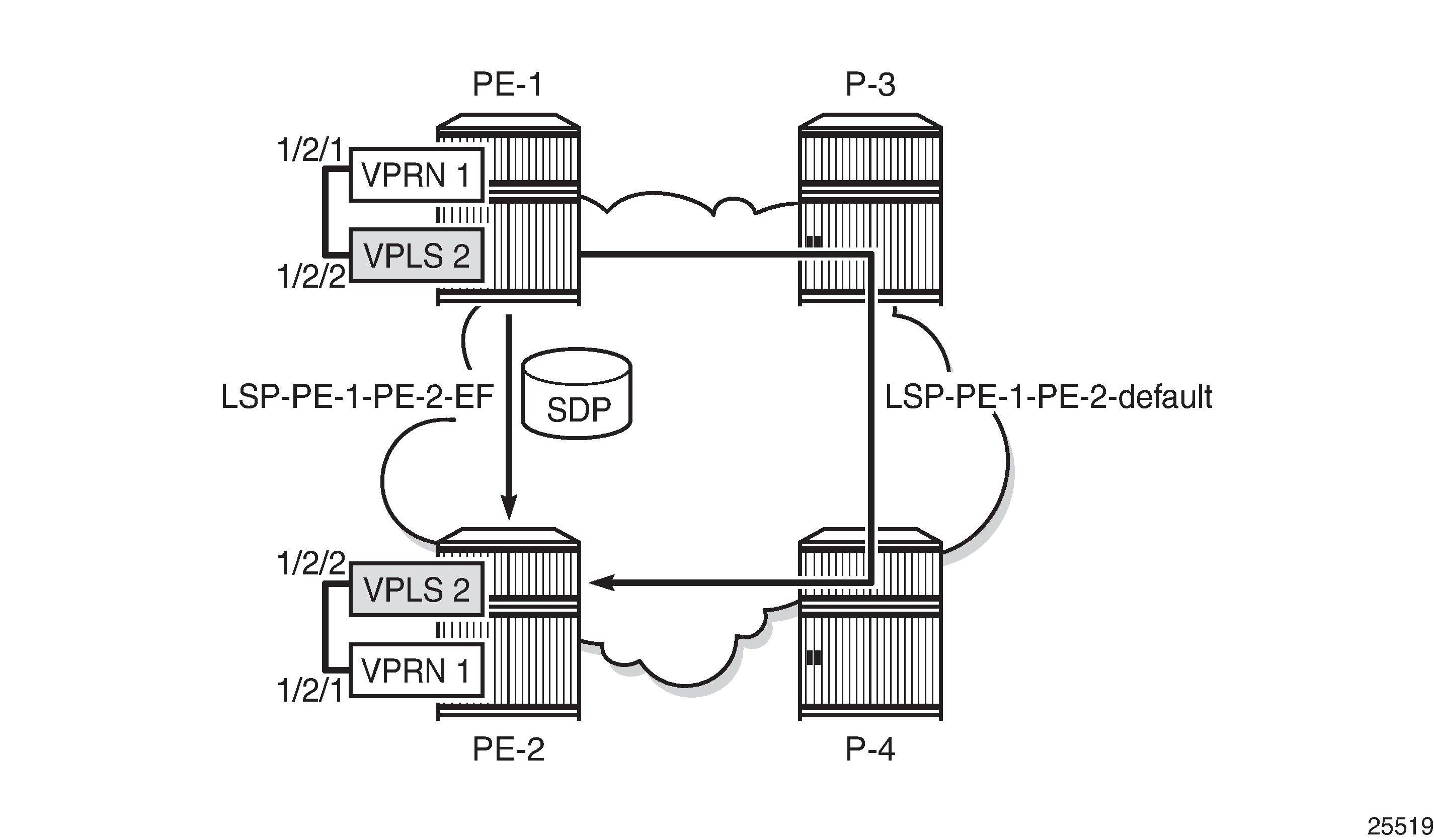
*A:PE-1# configure service
        vprn 1 customer 1 create
            route-distinguisher 64496:11
            vrf-target target:64496:1
            interface "loopback1" create
                address 172.31.1.1/32
                loopback
            exit
            interface "int-PE-1-PE-2-VPRN1" create
                address 192.168.112.1/30
                sap 1/2/1 create
                exit
            exit
            static-route-entry 172.31.2.1/32
                next-hop 192.168.112.2
                    no shutdown
                exit
            exit
            no shutdown
        exit
*A:PE-1# configure service
        vpls 2 customer 1 create
            description "VPLS to modify FC for traffic from VPRN 1"
            sap 1/2/2 create
            exit
            spoke-sdp 122:2 create
            exit
            no shutdown
        exit
The configuration of the services on PE-2 is similar.
The operational state of the spoke SDP can be verified as follows:
*A:PE-1# show service sdp-using
===============================================================================
SDP Using
===============================================================================
SvcId      SdpId              Type   Far End              Opr   I.Label E.Label
                                                          State
-------------------------------------------------------------------------------
2          122:2              Spok   192.0.2.2            Up    262139  262139
-------------------------------------------------------------------------------
Number of SDPs : 1
-------------------------------------------------------------------------------
===============================================================================
*A:PE-1#
Verify CBF on LSP for Specific FC
To verify that EF traffic is sent out on "LSP-PE-1-PE-2-EF", via port 1/1/2 on PE-1, the configuration of VPLS 2 needs to be modified. The default FC is set to EF.
The SAP ingress policy to set the FC to EF is applied in VPLS 2 on PE-1 as follows:
*A:PE-1# configure qos sap-ingress 2 create
            default-fc ef
            exit
*A:PE-1# configure service
        vpls 2
            sap 1/2/2 create
                ingress qos 2
            exit
        exit
The configuration is identical for PE-2.
First, the port statistics are cleared.
*A:PE-1# clear port 1/1/[1..2] statistics
One thousand ping messages will be sent from VPRN 1 on PE-1 to the loopback address in VPRN 1 on PE-2:
*A:PE-1# ping router 1 172.31.2.1 rapid count 1000
The port statistics are verified. The FC is equal to EF, so the LSP "LSP-PE-1-PE-2-EF" is used and the traffic is sent via port 1/1/2.
*A:PE-1# show port 1/1/1 statistics
===============================================================================
Port Statistics on Slot 1
===============================================================================
Port                    Ingress         Ingress         Egress           Egress
Id                      Packets          Octets         Packets          Octets
-------------------------------------------------------------------------------
1/1/1                        21            1740              21            1708
===============================================================================
*A:PE-1# show port 1/1/2 statistics
===============================================================================
Port Statistics on Slot 1
===============================================================================
Port                    Ingress         Ingress         Egress           Egress
Id                      Packets          Octets         Packets          Octets
-------------------------------------------------------------------------------
1/1/2                      1033          126954            1033          126898
===============================================================================
The traffic on the unused port (1/1/1) is not strictly equal to zero and the traffic on the used port (1/1/2) is not strictly equal to 1000, because of other traffic, such as OSPF messages.
Verify CBF on Default LSP
The SAP ingress policy to define the FC is removed from SAP 1/2/2 of VPLS 2. Traffic that enters a SAP where no SAP ingress policy with FC is defined always gets FC best effort (BE). Traffic with FC BE will be sent on the default LSP "LSP-PE-1-PE-2-default" on port 1/1/1 on PE-1, not on the direct link to PE-2.
*A:PE-1# configure service vpls 2 sap 1/2/2 ingress no qos 2
*A:PE-1# clear port 1/1/[1..2] statistics
*A:PE-1# ping router 1 172.31.2.1 rapid count 1000
The port statistics are verified. The FC is not equal to EF, so the default LSP is used and the traffic is sent via port 1/1/1.
*A:PE-1# show port 1/1/1 statistics
===============================================================================
Port Statistics on Slot 1
===============================================================================
Port                    Ingress         Ingress         Egress           Egress
Id                      Packets          Octets         Packets          Octets
-------------------------------------------------------------------------------
1/1/1                      1015          125284            1015          125284
===============================================================================
*A:PE-1# show port 1/1/2 statistics
===============================================================================
Port Statistics on Slot 1
===============================================================================
Port                    Ingress         Ingress         Egress           Egress
Id                      Packets          Octets         Packets          Octets
-------------------------------------------------------------------------------
1/1/2                        12            1068              12            1068
===============================================================================
Because no LSP has been configured to transport packets of classes other than EF, the default LSP will be used for all traffic classes different from EF. A similar outcome occurs when the FC of the ping messages is set to assured forwarding (AF), or any other FC different from EF.
The SAP ingress policy to set the FC to AF is applied in VPLS 2 on PE-1 as follows:
*A:PE-1# configure qos sap-ingress 2 create
            default-fc af
            exit
*A:PE-1# configure service
        vpls 2
            sap 1/2/2 create
                ingress qos 2
            exit
        exit
The configuration is identical for PE-2.
The port statistics are cleared and ping messages are sent. The result shows that the same port (that is, 1/1/1) is used for the generated traffic:
*A:PE-1# clear port 1/1/[1..2] statistics
*A:PE-1# ping router 1 172.31.2.1 rapid count 1000
*A:PE-1# show port 1/1/1 statistics
===============================================================================
Port Statistics on Slot 1
===============================================================================
Port                    Ingress         Ingress         Egress           Egress
Id                      Packets          Octets         Packets          Octets
-------------------------------------------------------------------------------
1/1/1                      1005          124342            1007          124750
===============================================================================
*A:PE-1# show port 1/1/2 statistics
===============================================================================
Port Statistics on Slot 1
===============================================================================
Port                    Ingress         Ingress         Egress           Egress
Id                      Packets          Octets         Packets          Octets
-------------------------------------------------------------------------------
1/1/2                        10             846              10             864
===============================================================================
*A:PE-1#
As indicated, the default LSP is used for all traffic with an FC that is not mapped to a specific LSP, which includes the case where a mapping FC-to-LSP has been defined but the LSP is not available. In the current example, all traffic with FC EF will be sent on LSP "LSP-PE-1-PE-2-EF", unless that LSP is unavailable. The default LSP will carry traffic with FC EF in that latter case.
The SAP ingress policy to assign the FC EF is applied in VPLS 2 on PE-1 as follows:
*A:PE-1# configure qos sap-ingress 2 create
            default-fc ef
            exit
*A:PE-1# configure service
        vpls 2
            sap 1/2/2 create
                ingress qos 2
            exit
        exit
The configuration is identical for PE-2.
To make the LSP "LSP-PE-1-PE-2-EF" unavailable, it is put in the shutdown state on PE-1. LSP "LSP-PE-2-PE-1-EF" on PE-2 is also put in the shutdown state.
*A:PE-1# configure router mpls lsp "LSP-PE-1-PE-2-EF" shutdown
*A:PE-2# configure router mpls lsp "LSP-PE-2-PE-1-EF" shutdown
The port statistics are cleared and ping messages are sent. The packets are classified as FC EF in VPLS 2:
*A:PE-1# clear port 1/1/[1..2] statistics
*A:PE-1# ping router 1 172.31.2.1 rapid count 1000
Because LSP "LSP-PE-1-PE-2-EF" (which uses port 1/1/2) is not operational, the traffic is sent on the default LSP on port 1/1/1 instead:
*A:PE-1# show port 1/1/1 statistics
===============================================================================
Port Statistics on Slot 1
===============================================================================
Port                    Ingress         Ingress         Egress           Egress
Id                      Packets          Octets         Packets          Octets
-------------------------------------------------------------------------------
1/1/1                      1010          124858            1009          124620
===============================================================================
*A:PE-1# show port 1/1/2 statistics
===============================================================================
Port Statistics on Slot 1
===============================================================================
Port                    Ingress         Ingress         Egress           Egress
Id                      Packets          Octets         Packets          Octets
-------------------------------------------------------------------------------
1/1/2                        14            1046              14            1046
===============================================================================
The LSP "LSP-PE-1-PE-2-EF" is re-enabled and the default LSP is now disabled. In this case, the SDP goes down. Ping messages will time out. The SAP ingress quality of service (QoS) policy in VPLS 2 is removed and the FC of the ping messages will no longer be changed to EF.
*A:PE-1# configure router mpls lsp "LSP-PE-1-PE-2-EF" no shutdown
*A:PE-1# configure router mpls lsp "LSP-PE-1-PE-2-default" shutdown
*A:PE-1# configure service vpls 2 sap 1/2/2 ingress no qos 2
The SDP is operational down when the default LSP is down, as can be verified:
*A:PE-1# show service sdp-using
===============================================================================
SDP Using
===============================================================================
SvcId      SdpId              Type   Far End              Opr   I.Label E.Label
                                                          State
-------------------------------------------------------------------------------
2          122:2              Spok   192.0.2.2            Down  262139  262139
-------------------------------------------------------------------------------
Number of SDPs : 1
-------------------------------------------------------------------------------
===============================================================================
*A:PE-1#
The default LSP is re-enabled.
*A:PE-1# configure router mpls lsp "LSP-PE-1-PE-2-default" no shutdown
Define Multicast LSP for BUM Traffic
The multicast LSP specifies the LSP in the SDP to use to forward BUM traffic. The LSP name must exist and must have been associated with this SDP. In this example, the default LSP is configured as the multicast LSP.
*A:PE-1# configure service sdp 122 class-forwarding multicast-lsp "LSP-PE-1-PE-2-default"
*A:PE-2# configure service sdp 212 class-forwarding multicast-lsp "LSP-PE-2-PE-1-default"
The SAP ingress policy to set the default FC to EF is enabled on SAP 1/2/2 in VPLS 2 in PE-1 and PE-2.
*A:PE-1# configure service vpls 2 sap 1/2/2 ingress qos 2
Ping messages are classified as FC EF in VPLS 2. This traffic is sent over "LSP-PE-1-PE-2-EF". However, if the traffic is unknown, it will be sent over the multicast LSP, which is "LSP-PE-1-PE-2-default". To get unknown traffic, the forwarding database (FDB) is cleared and MAC learning is disabled in VPLS 2 on PE-1.
*A:PE-1# clear service id 2 fdb all
*A:PE-1# configure service vpls 2 disable-learning
Clear port statistics and launch one thousand rapid ping messages in VPRN 1 on PE-1.
*A:PE-1# clear port 1/1/[1..2] statistics
*A:PE-1# ping router 1 172.31.2.1 rapid count 1000
Verify the port statistics. BUM traffic is sent on the multicast LSP "LSP-PE-1-PE-2-default" and the egress port on PE-1 is 1/1/1:
*A:PE-1# show port 1/1/1 statistics
===============================================================================
Port Statistics on Slot 1
===============================================================================
Port                    Ingress         Ingress         Egress           Egress
Id                      Packets          Octets         Packets          Octets
-------------------------------------------------------------------------------
1/1/1                      1010          124684            1011          124850
===============================================================================
*A:PE-1# show port 1/1/2 statistics
===============================================================================
Port Statistics on Slot 1
===============================================================================
Port                    Ingress         Ingress         Egress           Egress
Id                      Packets          Octets         Packets          Octets
-------------------------------------------------------------------------------
1/1/2                        14            1200              15            1310
===============================================================================
Re-enable MAC learning in VPLS 2.
*A:PE-1# configure service vpls 2 no disable-learning
Verify CBF in SDP
The CBF related information for SDP 122 in VPLS 2 on PE-1can be verified as follows:
*A:PE-1# show service id 2 sdp 122 detail
---snip---
-------------------------------------------------------------------------------
RSVP/Static LSPs
-------------------------------------------------------------------------------
Associated LSP List :
Lsp Name           : LSP-PE-1-PE-2-EF
Admin State        : Up                       Oper State        : Up
Time Since Last Tr*: 00h26m41s

Lsp Name           : LSP-PE-1-PE-2-default
Admin State        : Up                       Oper State        : Up
Time Since Last Tr*: 00h21m35s

-------------------------------------------------------------------------------
Class-based forwarding :
-------------------------------------------------------------------------------
Class forwarding   : Enabled                  EnforceDSTELspFc  : Disabled
Default LSP        : LSP-PE-1-PE-2-default    Multicast LSP     : LSP-PE-1-PE-*
===============================================================================
FC Mapping Table
===============================================================================
FC Name             LSP Name
-------------------------------------------------------------------------------
ef                  LSP-PE-1-PE-2-EF
===============================================================================
---snip---
The detailed information for the SDP contains all the LSPs configured in the SDP. CBF is enabled with default LSP "LSP-PE-1-PE-2-default". The multicast LSP is "LSP-PE-PE-2-default", but the name is truncated. The FC mapping table lists all FCs that have an LSP assigned. Each FC can only have one LSP assigned. Different FCs can have the same LSP assigned. In this example, only the FC EF has an LSP assigned.
Traffic statistics can be displayed per service per SDP. These statistics are not per LSP, so no distinction can be made between the different FCs.
*A:PE-1# show service id 2 sdp 122 detail
---snip---
Statistics            :
I. Fwd. Pkts.      : 9003                     I. Dro. Pkts.     : 0
I. Fwd. Octs.      : 882180                   I. Dro. Octs.     : 0
E. Fwd. Pkts.      : 9001                     E. Fwd. Octets    : 882060
---snip---
In this configuration example, the service using the SDP with CBF is a VPLS. The SDP can be used in a similar way by a VPRN.
An epipe service using CBF must have ingress shared-queuing enabled on access/SAP to work correctly.
CBF of LDP Prefix Packets over IGP Shortcuts
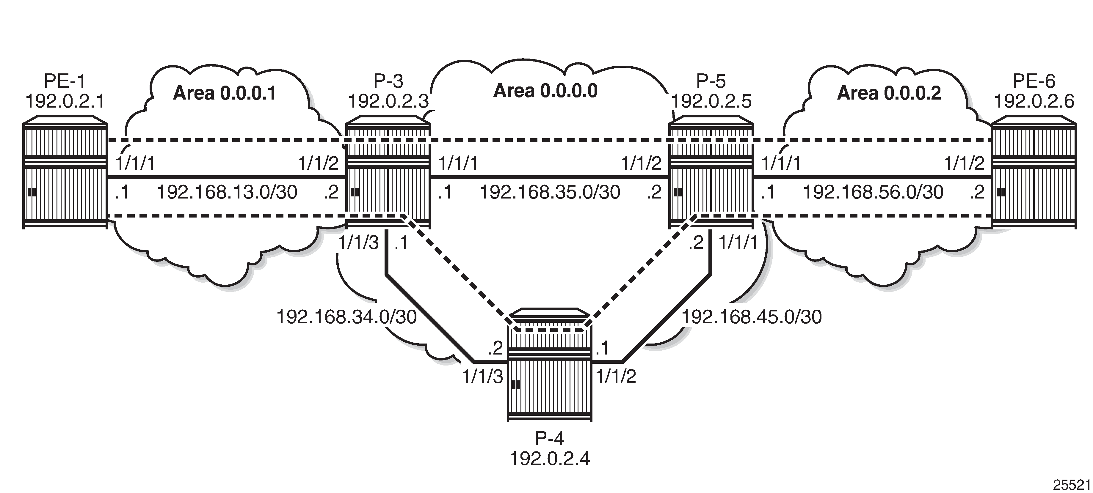
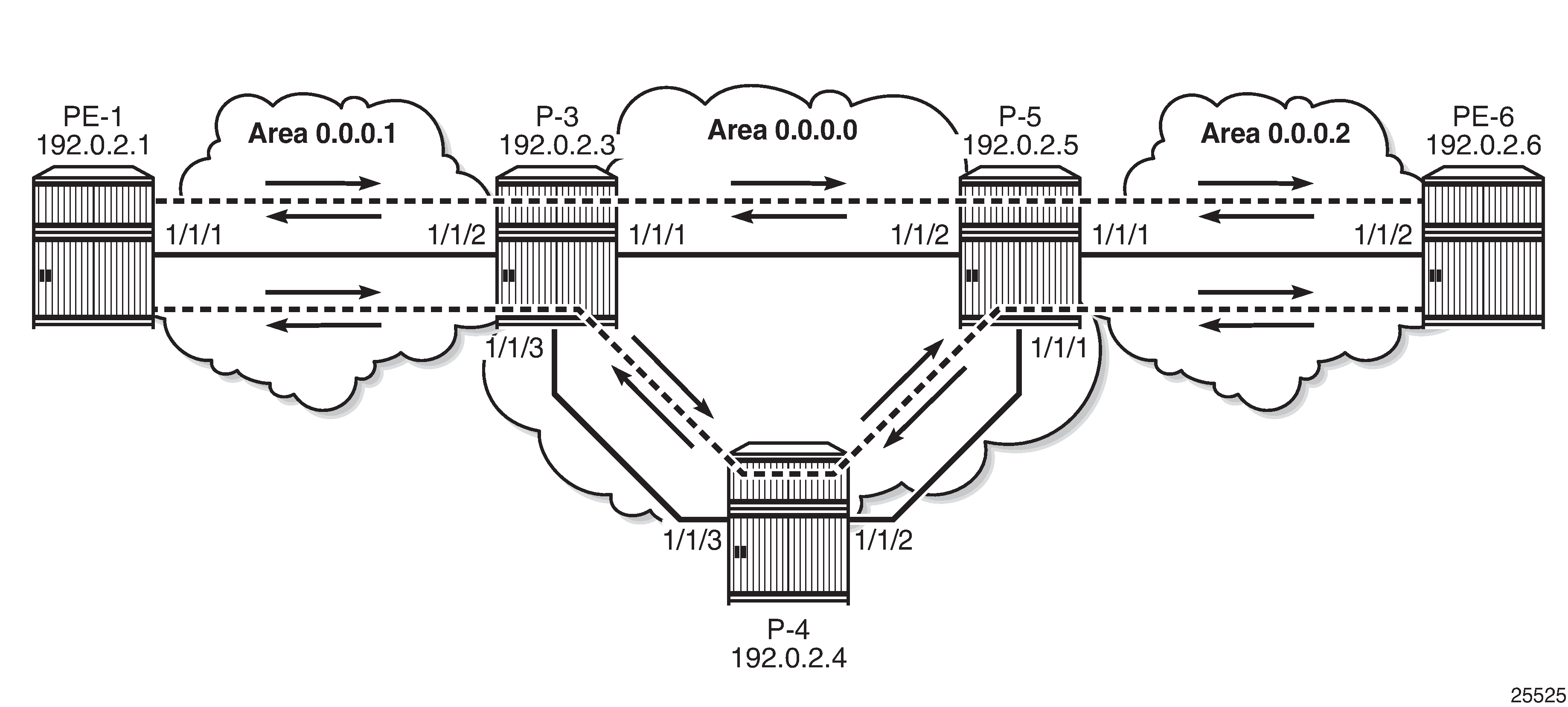
For this implementation, a more complex test topology is needed. Different OSPF areas are used.
In this example, traffic will be sent from VPRN 3 in PE-1 in OSPF area 0.0.0.1 to VPRN 3 in PE-6 in OSPF area 0.0.0.2. Most nodes used in the previous use case are reused, but some reconfiguration is required (router interfaces, OSPF areas, LSPs). For simplicity, PE-2 is not used anymore. The test topology is shown in Test Topology for CBF of LDP Prefix Packets over IGP Shortcuts.
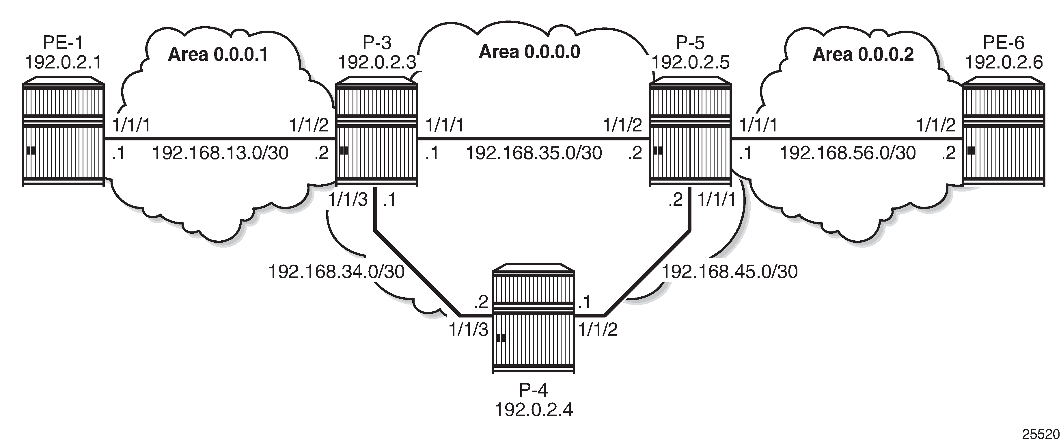
Initial Configuration
All nodes have the following initial configuration:
Cards, MDAs, ports
Router interfaces
IGP (here: OSPF) - PE-1 is now in OSPF area 0.0.0.1 instead of 0.0.0.0 in the preceding use case. P-3 and P-5 have interfaces in different areas:
*A:P-3# configure router
        ospf
            traffic-engineering
            area 0.0.0.0
                interface "system"
                exit
                interface "int-P-3-P-4"
                    interface-type point-to-point
                exit
                interface "int-P-3-P-5"
                    interface-type point-to-point
                exit
            exit
            area 0.0.0.1
                interface "int-P-3-PE-1"
                    interface-type point-to-point
                exit
            exit
            no shutdown
        exit
MPLS enabled on all router interfaces
RSVP enabled
RSVP LSPs:
Between PE-1 and P-3 in area 0.0.0.1 and between PE-6 and P-5 in area 0.0.0.2.
Between P-3 and P-5 in area 0.0.0.0, there are two LSPs in each direction: one LSP uses the direct strict path and the other LSP uses an indirect strict path via P-4. On P-3, the LSP "LSP-P-3-P-4-P-5" with indirect path will be used as the default LSP, while the LSP "LSP-P-3-P-5" with the direct path will be used for traffic with FC EF. For simplicity, there are no LSPs configured to or from P-4.
*A:P-3# configure router
        mpls
            path "path-P-3-PE-1"
                hop 10 192.168.13.1 strict
                no shutdown
            exit
            path "path-P-3-P-5"
                hop 10 192.168.35.2 strict
                no shutdown
            exit
            path "path-P-3-P-4-P-5"
                hop 10 192.168.34.2 strict
                hop 20 192.168.45.2 strict
                no shutdown
            exit
            lsp "LSP-P-3-PE-1"
                to 192.0.2.1
                primary "path-P-3-PE-1"
                exit
                no shutdown
            exit
            lsp "LSP-P-3-P-5"
                to 192.0.2.5
                primary "path-P-3-P-5"
                exit
                no shutdown
            exit
            lsp "LSP-P-3-P-4-P-5"
                to 192.0.2.5
                primary "path-P-3-P-4-P-5"
                exit
                no shutdown
            exit
            no shutdown
        exit
Configure IGP Shortcuts
IGP shortcut or forwarding adjacency must be enabled in one or more IGP instances. In the example, IGP shortcuts (RSVP shortcuts) are configured on all nodes:
IGP shortcut:
*A:PE-1# configure router ospf rsvp-shortcutForwarding adjacency (not configured in the example):
*A:PE-1# configure router ospf advertise-tunnel-link
By default, all LSPs are eligible for IGP shortcut. However, it is possible to exclude a specific RSVP LSP from being used in IGP shortcut as follows (this is not required in this example):
*A:PE-1# configure router mpls lsp "LSP-PE-1-P-3" no igp-shortcut
For more information on IGP Shortcuts, see chapter ‟IGP Shortcuts”.
Configure ECMP
ECMP must be enabled in the global routing instance. Nokia recommends that ECMP is set to a value that is at least equal to the number of FCs used by the packets forwarded using the LDP over RSVP tunnel.
In this case, two traffic flows are distinguished: traffic with FC EF takes one LSP while all other traffic takes the default LSP. Here, ECMP should be at least equal to 2. For simplicity, ECMP equal to 2 is only configured on P-3 and P-5:
*A:P-3# configure router ecmp 2
The selection of ECMP LSPs is done regardless of class-forwarding assignments, if any. The total number of LSPs with same cost, the number of those which have class-forwarding assignments, and the max-ecmp-routes parameter value influence the final set of LSPs, the consistency (from a CBF perspective) of which will be verified. These three factors must be carefully configured so as to ensure that the final set is consistent from a CBF perspective.
Enable LDP over RSVP
LDP over RSVP must be enabled between all PE routers and all P routers within the same area and between all P routers in the area 0:
*A:PE-1# configure router
        ldp
            targeted-session
                peer 192.0.2.3
                    tunneling
                    exit
                exit
            exit

*A:P-3# configure router
        ldp
            targeted-session
                peer 192.0.2.1
                    tunneling
                    exit
                exit
                peer 192.0.2.5
                    tunneling
                    exit
                exit
            exit
The LSP names configured in the tunneling context (if any) are not directly used by LDP when the rsvp-shortcut option is enabled. With IGP shortcuts, the set of tunnel next-hops is always provided by IGP in the routing table manager (RTM). The class-based forwarding rules will not apply to these named LSPs unless they are populated by IGP in the RTM as next-hops for a prefix.
The option prefer-tunnel-in-tunnel must be disabled (which is the default) for CBF to apply to LDP prefixes which are the endpoints of tunnels.
There is no need to enable LDP over RSVP on the LSPs. It is enabled by default, as can be verified with the following command:
*A:PE-1# show router mpls lsp "LSP-PE-1-PE-2-EF" detail | match LdpOverRsvp
LdpOverRsvp : Enabled                          VprnAutoBind   : Enabled
For more information on LDP over RSVP, see chapter ‟LDP over RSVP Using OSPF as IGP”.
Configure CBF of LDP Prefix Packets over IGP Shortcuts
Enable CBF of LDP prefix packets over IGP shortcuts with the following command in the ldp context on P-3 and P-5:
*A:P-3# configure router ldp class-forwarding
In this example, the PEs only have one path to the P routers. There is no need to enable class-forwarding.
When CBF is enabled, LDP prefixes resolved to a set of ECMP tunnel next-hops will have their packets forwarded to the LSP configured to carry the forwarding class that the packet was classified to at the ingress SAP, access interface, or network interface.
In Release 13.0.R6, this command is applicable for LSRs forwarding LDP forwarding equivalence class (FEC) prefix packets over a set of MPLS LSPs using IGP shortcuts. It is not supported for LER forwarding.
The command configure router ldp class-forwarding applies to the following contexts:
LER forwarding of packets of VPRN and L2 services that use auto-binding to LDP when the LDP FEC is resolved to a set of MPLS LSPs using IGP shortcuts. This is not supported in 13.0.R6.
LER forwarding of shortcut packets over LDP FEC that is resolved to a set of MPLS LSPs using IGP shortcuts. This is not supported in 13.0.R6.
LSR forwarding LDP FEC prefix packets over a set of MPLS LSPs using IGP shortcuts. This is supported in 13.0.R6.
This command does not apply to the following contexts:
LER forwarding of VPRN and L2 services over a user-provisioned SDP of type LDP when the LDP FEC is resolved to a set of MPLS LSPs using IGP shortcuts.
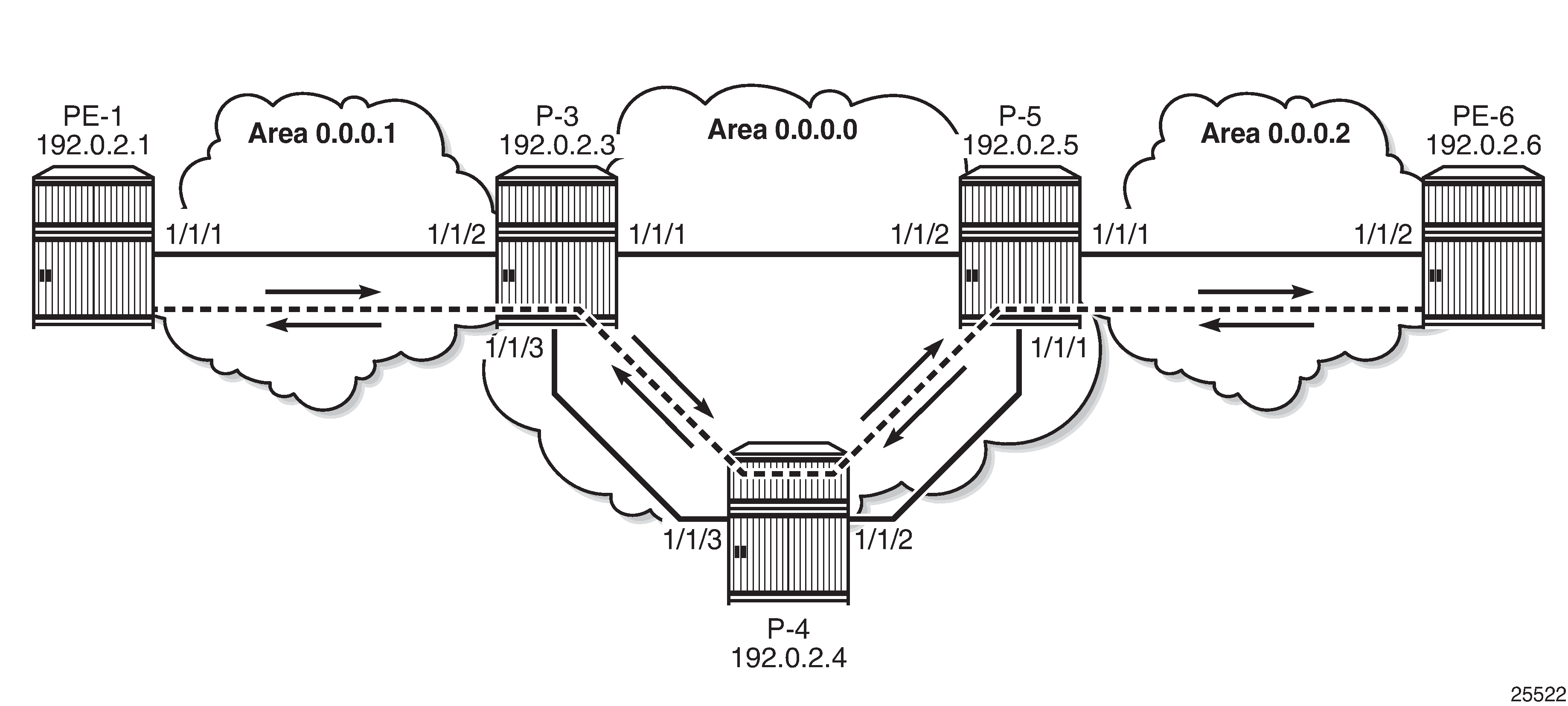
In this use case, the direct link from P-3 to P-5 should only be used for traffic with FC EF. The default LSP will take the longer path from P-3 via P-4 to P-5. The two different paths are shown in Different Paths for Different FCs.
The LSPs can be configured as follows:
*A:P-3# configure router
        mpls
           lsp "LSP-P-3-P-5"
                class-forwarding
                    fc ef
                exit
            exit
            lsp "LSP-P-3-P-4-P-5"
                class-forwarding
                    default-lsp
                exit
            exit
All traffic with an FC that is not mapped to a specific LSP will be mapped to the default LSP. The default LSP will also be used for traffic with FC EF, in case the dedicated LSP for that traffic is no longer available. It is possible to configure more than one default LSP, but only one will be used at a time.
The same LSP can be assigned to one or more FCs and be the default LSP at the same time.
*A:P-3# configure router
        mpls
            lsp "LSP-P-3-P-4-P-5"
                class-forwarding
                    fc be
                    default-lsp
                exit
            exit
The consistency of the configuration among the tunnel next-hops of an LDP FEC can only be verified by LDP at the time the FEC is resolved to IGP shortcuts. An example of an inconsistent configuration would be when class-forwarding is enabled while all tunnel next-hops for an LDP FEC have neither fc nor default-lsp assigned to them. LDP will then revert to ECMP routing for that FEC.
In this example, only P-3 and P-5 have ECMP equal to 2 and class-forwarding enabled.
Multiple LSPs can have the same FC assigned. Only one of these LSPs will be used to forward packets of this FC. That LSP is the one with the lowest tunnel ID.
Multiple LSPs can have the default-lsp configuration assigned, but only one of those will be the default LSP carrying all the traffic that should get the default treatment. That LSP is the one with the lowest tunnel ID.
If at least one LSP (amongst the ECMP set of LSPs) has an FC assigned, but no LSP has the default-lsp configuration, a single LSP will be automatically designated by LDP, even if all eight FCs have been mapped. A default LSP is needed to carry packets of an FC for which no explicit mapping to an LSP exists. The LSP with the lowest tunnel ID will be selected.
If none of the LSPs has an FC or default LSP configuration, the set is inconsistent and no CBF happens.
When the active LDP bindings are displayed, FECs resolved with CBF can be recognized by the (C) after the prefix:
*A:P-3# show router ldp bindings active prefixes prefix 192.0.2.6/32
===============================================================================
LDP Bindings (IPv4 LSR ID 192.0.2.3)
             (IPv6 LSR ID ::)
===============================================================================
Legend: U - Label In Use,  N - Label Not In Use, W - Label Withdrawn
        WP - Label Withdraw Pending, BU - Alternate For Fast Re-Route
        LF - Lower FEC, UF - Upper FEC
        (S) - Static           (M) - Multi-homed Secondary Support
        (B) - BGP Next Hop     (BU) - Alternate Next-hop for Fast Re-Route
        (I) - SR-ISIS Next Hop (O) - SR-OSPF Next Hop
        (C) - FEC resolved with class-based-forwarding
===============================================================================
LDP IPv4 Prefix Bindings (Active)
===============================================================================
Prefix                                      Op              IngLbl    EgrLbl
EgrNextHop                                  EgrIf/LspId
-------------------------------------------------------------------------------
192.0.2.6/32                                Push              --      262136
192.0.2.5                                   LspId 2

192.0.2.6/32                                Push              --      262136
192.0.2.5                                   LspId 3

192.0.2.6/32(C)                             Swap            262133    262136
192.0.2.5                                   LspId 2

192.0.2.6/32(C)                             Swap            262133    262136
192.0.2.5                                   LspId 3

-------------------------------------------------------------------------------
No. of IPv4 Prefix Active Bindings: 4
===============================================================================
*A:P-3#
Only the entries that correspond to swap operations get the (C) added. The entries that correspond to push operations do not get the (C) because CBF is not supported for LERs in 13.0.R6.
Traffic that is sent from PE-1 to PE-6 will be forwarded on P-3 based on the FC, while traffic that originates on P-3 will not be subjected to CBF.
LSP 2 uses the direct path from P-3 to P-5 while LSP 3 uses the indirect path from P-3 to P-5 via P-4. This can be verified in the tunnel table:
*A:P-3# show router tunnel-table
===============================================================================
IPv4 Tunnel Table (Router: Base)
===============================================================================
Destination       Owner     Encap TunnelId  Pref     Nexthop        Metric
-------------------------------------------------------------------------------
192.0.2.1/32      rsvp      MPLS  1         7        192.168.13.1   16777215
192.0.2.1/32      ldp       MPLS  65537     9        192.0.2.1      65535
192.0.2.5/32      rsvp      MPLS  2         7        192.168.35.2   16777215
192.0.2.5/32      rsvp      MPLS  3         7        192.168.34.2   16777215
192.0.2.5/32      ldp       MPLS  65538     9        192.0.2.5      65535
192.0.2.6/32      ldp       MPLS  65539     9        192.0.2.5      131070
-------------------------------------------------------------------------------
Flags: B = BGP backup route available
       E = inactive best-external BGP route
===============================================================================
*A:P-3#
The LSP that uses the direct path to P-5 has the lowest tunnel ID. When both LSPs are configured as default LSP, the LSP with the lowest tunnel ID will effectively be used as the default LSP. In the current configuration, only the LSP using the indirect path is configured as the default LSP.
Verify CBF
Traffic will be sent from a VPRN on PE-1 to a VPRN on PE-6 and back.
Configure VPRN
On PE-1 and PE-6, a VPRN service needs to be configured. BGP will be used to exchange VPN routes.
Import and export policies are configured as follows:
*A:PE-1# configure router
        policy-options
            begin
            community "VPN3" members "target:64496:3"
            policy-statement "VPN3-export"
                entry 10
                    from
                        protocol direct
                    exit
                    to
                        protocol bgp-vpn
                    exit
                    action accept
                        community add "VPN3"
                    exit
                exit
            exit
            policy-statement "VPN3-import"
                entry 10
                    from
                        protocol bgp-vpn
                        community "VPN3"
                    exit
                    action accept
                    exit
                exit
            exit
            commit
        exit
The VPRN is configured using auto-bind-tunnel with resolution-filter ldp, as follows:
*A:PE-1# configure service
        vprn 3 customer 1 create
            vrf-import "VPN3-import"
            vrf-export "VPN3-export"
            route-distinguisher 64496:31
            auto-bind-tunnel
                resolution-filter
                    ldp
                exit
                resolution filter
            exit
            interface "loopback3" create
                address 172.31.1.3/32
                loopback
            exit
            no shutdown
        exit
For BGP, P-5 is used as route reflector. The address family is VPN-IPv4.
*A:PE-1# configure router
        autonomous-system 64496
        bgp
            family vpn-ipv4
            group "internal"
                peer-as 64496
                neighbor 192.0.2.5
                exit
            exit
            no shutdown
        exit

*A:P-5# configure router
        bgp
        autonomous-system 64496
            family vpn-ipv4
            cluster 1.1.1.1
            group "internal"
                peer-as 64496
                neighbor 192.0.2.1
                exit
                neighbor 192.0.2.3
                exit
                neighbor 192.0.2.4
                exit
                neighbor 192.0.2.6
                exit
            exit
            no shutdown
        exit
The routes are learned, as can be verified with the following command:
*A:PE-1# show router 3 route-table
===============================================================================
Route Table (Service: 3)
===============================================================================
Dest Prefix[Flags]                            Type    Proto     Age        Pref
      Next Hop[Interface Name]                                    Metric
-------------------------------------------------------------------------------
172.31.1.3/32                                 Local   Local     00h21m08s  0
       loopback3                                                    0
172.31.6.3/32                                 Remote  BGP VPN   00h10m47s  170
       192.0.2.6 (tunneled)                                         0
-------------------------------------------------------------------------------
No. of Routes: 2
Flags: n = Number of times nexthop is repeated
       B = BGP backup route available
       L = LFA nexthop available
       S = Sticky ECMP requested
===============================================================================
*A:PE-1#
Verify Traffic Flow - Default LSP
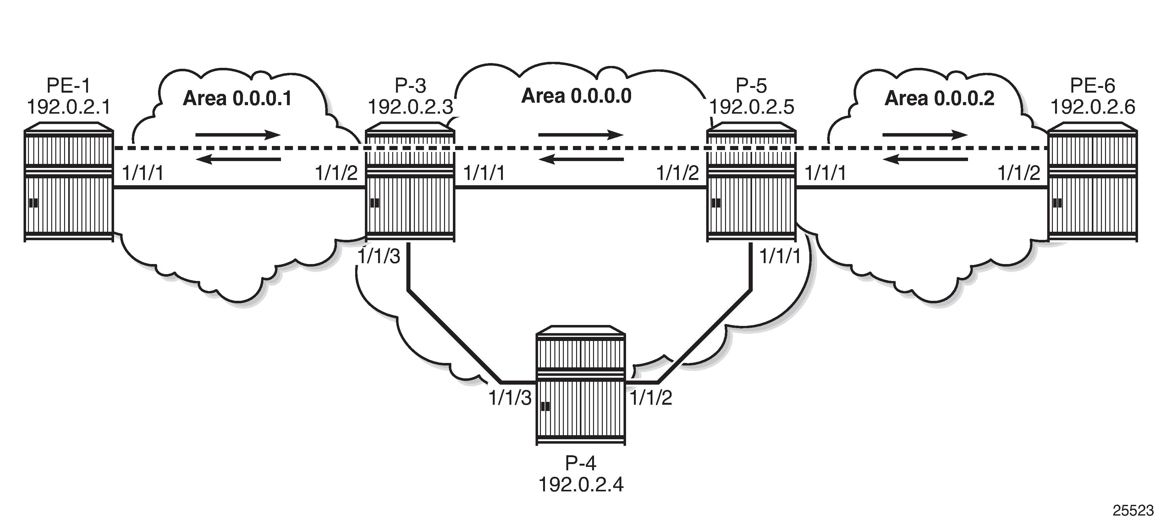
When ping messages are sent from the VPRN on PE-1 to the VPRN on PE-6, the traffic will be forwarded according to the FC at the LSRs. The FC is not manipulated yet. For P-3, the traffic will be sent on the default LSP to P-5 via P-4. On node P-3, the ingress port for traffic destined to PE-6 is 1/1/2 and the egress port to P-4 is 1/1/3. The ping replies will follow the reverse path. The traffic flow is shown in Traffic on Default LSP.
*A:P-3# clear port 1/1/[1..3] statistics
*A:PE-1# ping router 3 172.31.6.3 rapid count 1000
*A:P-3# show port 1/1/1 statistics
===============================================================================
Port Statistics on Slot 1
===============================================================================
Port                    Ingress         Ingress         Egress           Egress
Id                      Packets          Octets         Packets          Octets
-------------------------------------------------------------------------------
1/1/1                        25            2548              24            2322
===============================================================================
*A:P-3# show port 1/1/2 statistics
===============================================================================
Port Statistics on Slot 1
===============================================================================
Port                    Ingress         Ingress         Egress           Egress
Id                      Packets          Octets         Packets          Octets
-------------------------------------------------------------------------------
1/1/2                      1029          116738            1030          116844
===============================================================================
*A:P-3# show port 1/1/3 statistics
===============================================================================
Port Statistics on Slot 1
===============================================================================
Port                    Ingress         Ingress         Egress           Egress
Id                      Packets          Octets         Packets          Octets
-------------------------------------------------------------------------------
1/1/3                      1037          118074            1040          118648
===============================================================================
*A:P-3#
With the same commands, the traffic flow on the other nodes can be verified. P-4 has traffic on port 1/1/3 (to P-3) and on port 1/1/2 (to P-5). P-5 has traffic on port 1/1/1 (to P-4) and port 1/1/3 (to PE-6).
Verify Traffic Flow - LSP for FC EF
On nodes P-3 and P-5, the FC is set to EF at the ingress of the interface to the PE router.
*A:P-3# configure qos
        network 2 create
            ingress
                default-action fc ef profile in
            exit
        exit
*A:P-3# configure router interface "int-P-3-PE-1" qos 2
When the FC is modified to EF, the traffic takes the direct path between P-3 and P-5. On node P-3, traffic will be sent to and received from P-5 on port 1/1/1, as shown in Traffic with FC EF on Direct Path.
*A:P-3# clear port 1/1/[1..3] statistics
*A:PE-1# ping router 3 172.31.6.3 rapid count 1000
*A:P-3# show port 1/1/1 statistics
===============================================================================
Port Statistics on Slot 1
===============================================================================
Port                    Ingress         Ingress         Egress           Egress
Id                      Packets          Octets         Packets          Octets
-------------------------------------------------------------------------------
1/1/1                      1015          115276            1015          115276
===============================================================================
*A:P-3# show port 1/1/2 statistics
===============================================================================
Port Statistics on Slot 1
===============================================================================
Port                    Ingress         Ingress         Egress           Egress
Id                      Packets          Octets         Packets          Octets
-------------------------------------------------------------------------------
1/1/2                      1024          116136            1024          116004
===============================================================================
*A:P-3# show port 1/1/3 statistics
===============================================================================
Port Statistics on Slot 1
===============================================================================
Port                    Ingress         Ingress         Egress           Egress
Id                      Packets          Octets         Packets          Octets
-------------------------------------------------------------------------------
1/1/3                        22            1834              23            2062
===============================================================================
*A:P-3#
The original configuration is restored by removing the QoS network policy from the interface to the PE as follows:
*A:P-3# configure router interface "int-P-3-PE-1" no qos
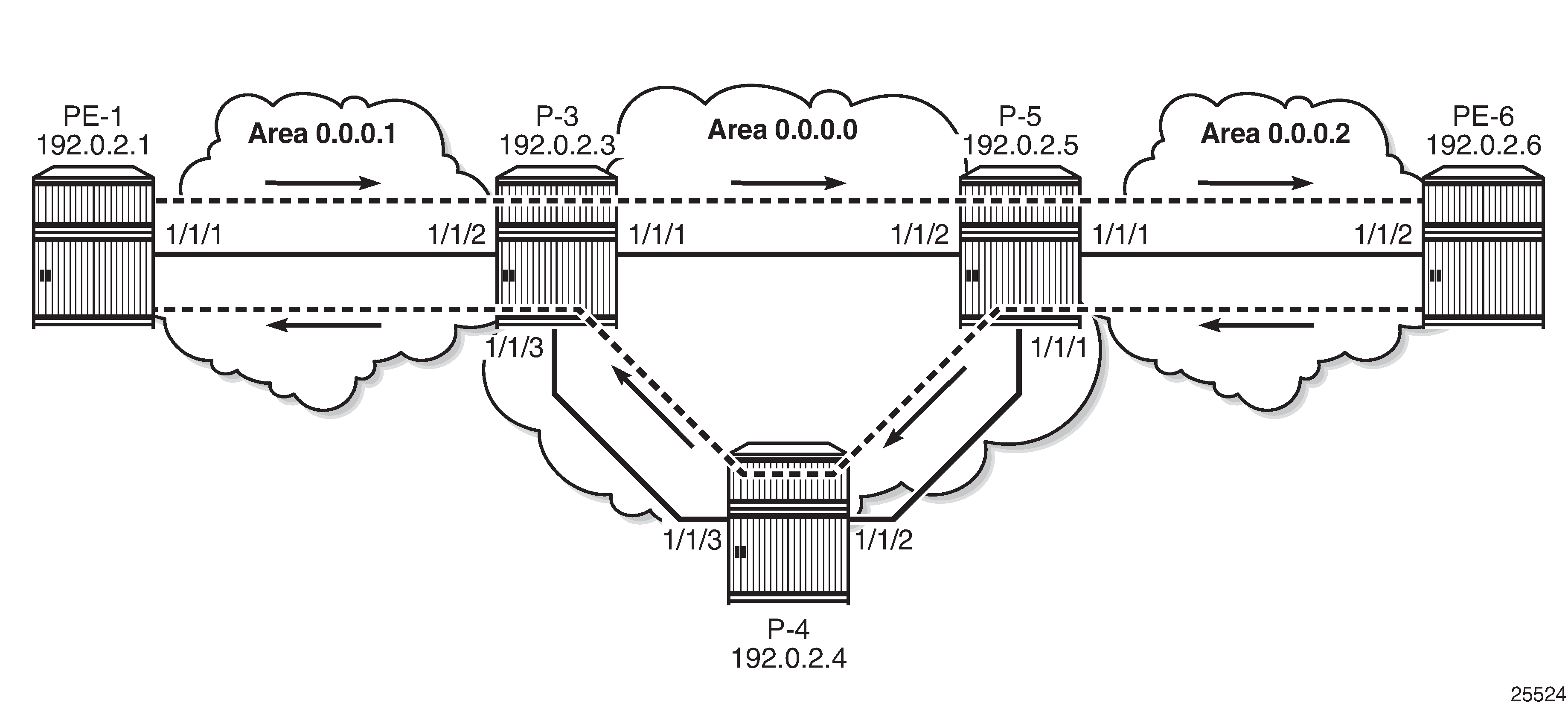
Verify Traffic Flow - Multiple LSPs Configured as Default LSP on P-3
The FC is not manipulated anymore. On P-3, LSP "LSP-P-3-P-4-P-5" was configured as default LSP. Additionally, also LSP "LSP-P-3-P-5" is configured as a default LSP. So "LSP-P-3-P-5" becomes the used default LSP, because the tunnel ID (equal to 2) is lower than the tunnel ID of the LSP using the long path from P-3 to P-5 via P-4 (equal to 3). When this is configured on P-3, without changing anything to the configuration at P-5, the behavior is asymmetric. Incoming traffic on port 1/1/2 is forwarded to P-5 via port 1/1/1, while the ping replies still take the long path using ingress port 1/1/3 on P-3 The traffic flow is shown in Traffic on Default LSP with Lowest ID on P-3.
*A:P-3# configure router
        mpls
            lsp "LSP-P-3-P-5"
                class-forwarding
                    default-lsp
                exit
*A:P-3# clear port 1/1/[1..3] statistics
*A:PE-1# ping router 3 172.31.6.3 rapid count 1000
*A:P-3# show port 1/1/1 statistics
===============================================================================
Port Statistics on Slot 1
===============================================================================
Port                    Ingress         Ingress         Egress           Egress
Id                      Packets          Octets         Packets          Octets
-------------------------------------------------------------------------------
1/1/1                        22            1904            1028          116819
===============================================================================
*A:P-3# show port 1/1/2 statistics
===============================================================================
Port Statistics on Slot 1
===============================================================================
Port                    Ingress         Ingress         Egress           Egress
Id                      Packets          Octets         Packets          Octets
-------------------------------------------------------------------------------
1/1/2                      1029          116813            1025          116289
===============================================================================
*A:P-3# show port 1/1/3 statistics
===============================================================================
Port Statistics on Slot 1
===============================================================================
Port                    Ingress         Ingress         Egress           Egress
Id                      Packets          Octets         Packets          Octets
-------------------------------------------------------------------------------
1/1/3                      1031          117375              32            3520
===============================================================================
*A:P-3#
*A:P-3# show router tunnel-table
===============================================================================
IPv4 Tunnel Table (Router: Base)
===============================================================================
Destination       Owner     Encap TunnelId  Pref     Nexthop        Metric
-------------------------------------------------------------------------------
192.0.2.1/32      rsvp      MPLS  1         7        192.168.13.1   16777215
192.0.2.1/32      ldp       MPLS  65550     9        192.0.2.1      65535
192.0.2.5/32      rsvp      MPLS  2         7        192.168.35.2   16777215
192.0.2.5/32      rsvp      MPLS  3         7        192.168.34.2   16777215
192.0.2.5/32      ldp       MPLS  65553     9        192.0.2.5      65535
192.0.2.6/32      ldp       MPLS  65554     9        192.0.2.5      131070
-------------------------------------------------------------------------------
Flags: B = BGP backup route available
       E = inactive best-external BGP route
===============================================================================
*A:P-3#
The original configuration is restored. The LSP with the direct path will only be used for traffic with FC EF ("LSP-P-3-P-5" remained an EF LSP even when it became a default LSP):
*A:P-3# configure router mpls lsp "LSP-P-3-P-5" class-forwarding no default-lsp
Verify Traffic Flow - No Default LSP Configured
When the class-forwarding configuration for the different LSPs always has one or more FCs and no default LSP, the system will select a default LSP itself. This can be tested by removing the default LSP configuration from all LSPs on P-3 and P-5 and adding FC AF instead. FC AF does not correspond to the FC of the ping messages; therefore, a default LSP will be required.
*A:P-3# configure router mpls lsp "LSP-P-3-P-4-P-5" class-forwarding no default-lsp
*A:P-3# configure router mpls lsp "LSP-P-3-P-4-P-5" class-forwarding fc af
*A:P-5# configure router mpls lsp "LSP-P-5-P-4-P-3" class-forwarding no default-lsp
*A:P-5# configure router mpls lsp "LSP-P-5-P-4-P-3" class-forwarding fc af
The actual CBF configuration does not include any default LSPs anymore:
*A:P-3>config>router>mpls# info
----------------------------------------------
---snip---
            lsp "LSP-P-3-P-5"
                to 192.0.2.5
                class-forwarding
                    fc ef
                exit
                primary "path-P-3-P-5"
                exit
                no shutdown
            exit
            lsp "LSP-P-3-P-4-P-5"
                to 192.0.2.5
                class-forwarding
                    fc af
                exit
                primary "path-P-3-P-4-P-5"
                exit
                no shutdown
            exit
The system selects the LSP with the lowest tunnel ID as the default LSP, in this case the LSP using the direct path between P-3 and P-5, as shown in Traffic on System-Selected Default LSPs with Lowest Tunnel ID.
The tunnel ID can be verified in the tunnel table. The tunnel table for P-3 has already been shown in the preceding section.
On P-5, the LSP to P-3 with the tunnel ID 2 has next hop 192.168.35.1, as can be verified in the tunnel table. This corresponds to LSP "LSP-P-5-P-3". The LSP with tunnel ID 3 and next hop 192.168.45.1 corresponds to LSP "LSP-P-5-P-4-P-3".
*A:P-5# show router tunnel-table
===============================================================================
IPv4 Tunnel Table (Router: Base)
===============================================================================
Destination       Owner     Encap TunnelId  Pref     Nexthop        Metric
-------------------------------------------------------------------------------
192.0.2.1/32      ldp       MPLS  65552     9        192.0.2.3      131070
192.0.2.3/32      rsvp      MPLS  2         7        192.168.35.1   16777215
192.0.2.3/32      rsvp      MPLS  3         7        192.168.45.1   16777215
192.0.2.3/32      ldp       MPLS  65551     9        192.0.2.3      65535
192.0.2.6/32      rsvp      MPLS  1         7        192.168.56.2   16777215
192.0.2.6/32      ldp       MPLS  65553     9        192.0.2.6      65535
-------------------------------------------------------------------------------
Flags: B = BGP backup route available
       E = inactive best-external BGP route
===============================================================================
*A:P-5#
On P-3, incoming traffic from PE-1 will be forwarded on port 1/1/1 toward P-5.
*A:P-3# clear port 1/1/[1..3] statistics
*A:PE-1# ping router 3 172.31.6.3 rapid count 1000

*A:P-3# show port 1/1/1 statistics
===============================================================================
Port Statistics on Slot 1
===============================================================================
Port                    Ingress         Ingress         Egress           Egress
Id                      Packets          Octets         Packets          Octets
-------------------------------------------------------------------------------
1/1/1                      1024          116120            1022          115840
===============================================================================
*A:P-3# show port 1/1/2 statistics
===============================================================================
Port Statistics on Slot 1
===============================================================================
Port                    Ingress         Ingress         Egress           Egress
Id                      Packets          Octets         Packets          Octets
-------------------------------------------------------------------------------
1/1/2                      1026          116221            1028          116325
===============================================================================
*A:P-3# show port 1/1/3 statistics
===============================================================================
Port Statistics on Slot 1
===============================================================================
Port                    Ingress         Ingress         Egress           Egress
Id                      Packets          Octets         Packets          Octets
-------------------------------------------------------------------------------
1/1/3                        26            2142              25            2174
===============================================================================
*A:P-3#
No CBF in Case of Inconsistent Configuration
The FC LSP and default LSPs are removed from P-3 and P-5. Class-forwarding remains enabled, but the configuration is inconsistent and the forwarding behavior reverts to ECMP routing.
*A:P-3# configure router mpls lsp "LSP-P-3-P-4-P-5" class-forwarding no default-lsp
*A:P-3# configure router mpls lsp "LSP-P-3-P-4-P-5" class-forwarding no fc af
*A:P-3# configure router mpls lsp "LSP-P-3-P-5" class-forwarding no fc ef
*A:P-5# configure router mpls lsp "LSP-P-5-P-4-P-3" class-forwarding no default-lsp
*A:P-5# configure router mpls lsp "LSP-P-5-P-4-P-3" class-forwarding no fc af
*A:P-5# configure router mpls lsp "LSP-P-5-P-3" class-forwarding no fc ef
*A:P-3>config>router>mpls# info
----------------------------------------------
---snip---
            lsp "LSP-P-3-P-5"
                to 192.0.2.5
                class-forwarding
                exit
                primary "path-P-3-P-5"
                exit
                no shutdown
            exit
            lsp "LSP-P-3-P-4-P-5"
                to 192.0.2.5
                class-forwarding
                exit
                primary "path-P-3-P-4-P-5"
                exit
                no shutdown
            exit
            no shutdown
ECMP equals 2, so the traffic flows will be distributed over the two LSPs between P-3 and P-5, as can be verified in the routing tables at P-3 and P-5:
*A:P-3# show router route-table
===============================================================================
Route Table (Router: Base)
===============================================================================
Dest Prefix[Flags]                            Type    Proto     Age        Pref
      Next Hop[Interface Name]                                    Metric
-------------------------------------------------------------------------------
192.0.2.1/32                                  Remote  OSPF      03h05m18s  10
       192.0.2.1 (tunneled:RSVP:1)                                  65535
192.0.2.3/32                                  Local   Local     04h56m20s  0
       system                                                       0
192.0.2.4/32                                  Remote  OSPF      04h40m38s  10
       192.168.34.2                                                 10
192.0.2.5/32                                  Remote  OSPF      00h00m06s  10
       192.0.2.5 (tunneled:RSVP:2)                                  65535
192.0.2.5/32                                  Remote  OSPF      00h00m06s  10
       192.0.2.5 (tunneled:RSVP:3)                                  65535
192.0.2.6/32                                  Remote  OSPF      00h00m06s  10
       192.0.2.5 (tunneled:RSVP:2)                                  131070
192.0.2.6/32                                  Remote  OSPF      00h00m06s  10
       192.0.2.5 (tunneled:RSVP:3)                                  131070
---snip---

*A:P-5# show router route-table 192.0.2.1/32
===============================================================================
Route Table (Router: Base)
===============================================================================
Dest Prefix[Flags]                            Type    Proto     Age        Pref
      Next Hop[Interface Name]                                    Metric
-------------------------------------------------------------------------------
192.0.2.1/32                                  Remote  OSPF      00h01m06s  10
       192.0.2.3 (tunneled:RSVP:2)                                  131070
192.0.2.1/32                                  Remote  OSPF      00h01m06s  10
       192.0.2.3 (tunneled:RSVP:3)                                  131070
-------------------------------------------------------------------------------
No. of Routes: 2
Flags: n = Number of times nexthop is repeated
       B = BGP backup route available
       L = LFA nexthop available
       S = Sticky ECMP requested
===============================================================================
*A:P-5#
The ECMP hashing algorithm will hash on the source and destination IP address. As long as they are the same for each packet, the traffic will be sent on the same link. Therefore, different traffic flows need to be generated in parallel from PE-1 to PE-6. It is possible to create additional loopback interfaces in VPRN 3, but for this test, the system IP addresses of PE-1 and PE-6 can also be used. The ping messages are not sent after one another, but parallel in two different sessions with PE-1.
Inconsistent CBF Configuration. Revert to ECMP Forwarding shows that different traffic flows are sprayed over the different LSPs. The returning traffic need not take the same path.
*A:P-3# clear port 1/1/[1..3] statistics
*A:PE-1# ping router 3 172.31.6.3 rapid count 2000
*A:PE-1# ping 192.0.2.6 rapid count 2000
*A:P-3# show port 1/1/1 statistics
===============================================================================
Port Statistics on Slot 1
===============================================================================
Port                    Ingress         Ingress         Egress           Egress
Id                      Packets          Octets         Packets          Octets
-------------------------------------------------------------------------------
1/1/1                      2052          216350              54            4745
===============================================================================
*A:P-3# show port 1/1/2 statistics
===============================================================================
Port Statistics on Slot 1
===============================================================================
Port                    Ingress         Ingress         Egress           Egress
Id                      Packets          Octets         Packets          Octets
-------------------------------------------------------------------------------
1/1/2                      4054          445019            4055          444877
===============================================================================
*A:P-3# show port 1/1/3 statistics
===============================================================================
Port Statistics on Slot 1
===============================================================================
Port                    Ingress         Ingress         Egress           Egress
Id                      Packets          Octets         Packets          Octets
-------------------------------------------------------------------------------
1/1/3                      2048          232178            4042          443622
===============================================================================
*A:P-3#
In this case, all traffic from PE-1 to PE-6 for both traffic flows takes the LSP "LSP-P-3-P-4-P-5". The returning traffic is distributed over the LSPs "LSP-P-5-P-3" and "LSP-P-5-P-4-P-3". ECMP works, but there are not enough traffic flows to show it more clearly.
Conclusion
Within a service, traffic with different FCs can be forwarded using different paths, depending on the requirements for latency and jitter. This is also the case for services traversing multiple domains.
CBF is a local decision and need not be enabled on all intermediate routers. This allows for better interoperability.