Inter-Area TE Point-to-Point LSPs
This chapter describes inter-area Traffic Engineering (TE) Point-to-Point (P2P) Label Switched Paths (LSPs) configurations.
Topics in this chapter include:
Applicability
This chapter was initially written for SR OS Release 11.0.R4, but the CLI in the current edition corresponds to SR OS Release 21.2.R1.
Overview
Multi-Protocol Label Switching with Traffic Engineering (MPLS TE) is implemented on a wide scale in current Internet Service Provider (ISP) networks to steer traffic across their backbones to facilitate efficient use of available bandwidth between the routers and to guarantee fast convergence in case a link or node fails.
Regular TE LSPs in MPLS networks are confined to only a single Interior Gateway Protocol (IGP) area or level. This is because the head-end has information in the TE database of only the local area for Open Shortest Path First (OSPF) or level for Intermediate System to Intermediate System (IS-IS). As the name implies, inter-area TE LSPs can cross the area or level borders of the IGP.
Inter-Area TE LSP based on Explicit Route expansion
Inter-area TE LSP using Explicit Route Object (ERO) expansion enables the head-end to calculate the ERO path within its own area or level and keep the remaining Area Border Routers (ABRs) of other areas/levels as loose hops in the ERO path. On receiving a PATH message with a loose hop ERO and based on local configuration, each ABR does a partial Constrained Shortest Path First (CSPF) calculation to the next ABR or a full CSPF calculation to reach the destination.
Automatic selection of ABRs is supported so that the head-end node can work with an empty primary path. When the to field of an LSP definition is in an area/level different from the head-end node, CSPF will automatically compute the segment to the exit ABR router which advertised the prefix and which currently is the best path for resolving the prefix in the Route Table Manager (RTM).
ABR protection
Link and node protection within the respective areas are supported through the TE capabilities of the IGP and Resource Reservation Protocol (RSVP) in each area. To support ABR node protection, a bypass is required from the Point of Local Repair (PLR; node prior to ABR) to the Merge Point (MP; next-hop node to ABR).
Two methods are possible: static ABR protection and dynamic ABR protection. Static ABR protection uses Manual Bypass Tunnels (MBTs), statically configured by the operator between the PLR and the MP. For dynamic ABR protection, node ID propagation and signaling of an eXclude Route Object (XRO) in RSVP PATH messages must both be supported.
Because the Record Route Object (RRO) Node ID sub-object description in RFC 4561, Definition of a Record Route Object (RRO) Node-Id Sub-Object, is not clear about the format of the included node address (S), interface address (I) and label (L), the system supports multiple formats: IL, SL, ISL, SIL, SLI, ILSL and SLIL. The system uses the SLIL (node-address, label, interface-address, label) format to include the node ID itself.
The exclude route object (XRO) inclusion (RFC 4874, Exclude Routes - Extension to Resource ReserVation Protocol-Traffic Engineering) in bypass RSVP PATH messages is required to exclude the protected ABR from the bypass path. The XRO object contains the ABR system IP address.
Example topology
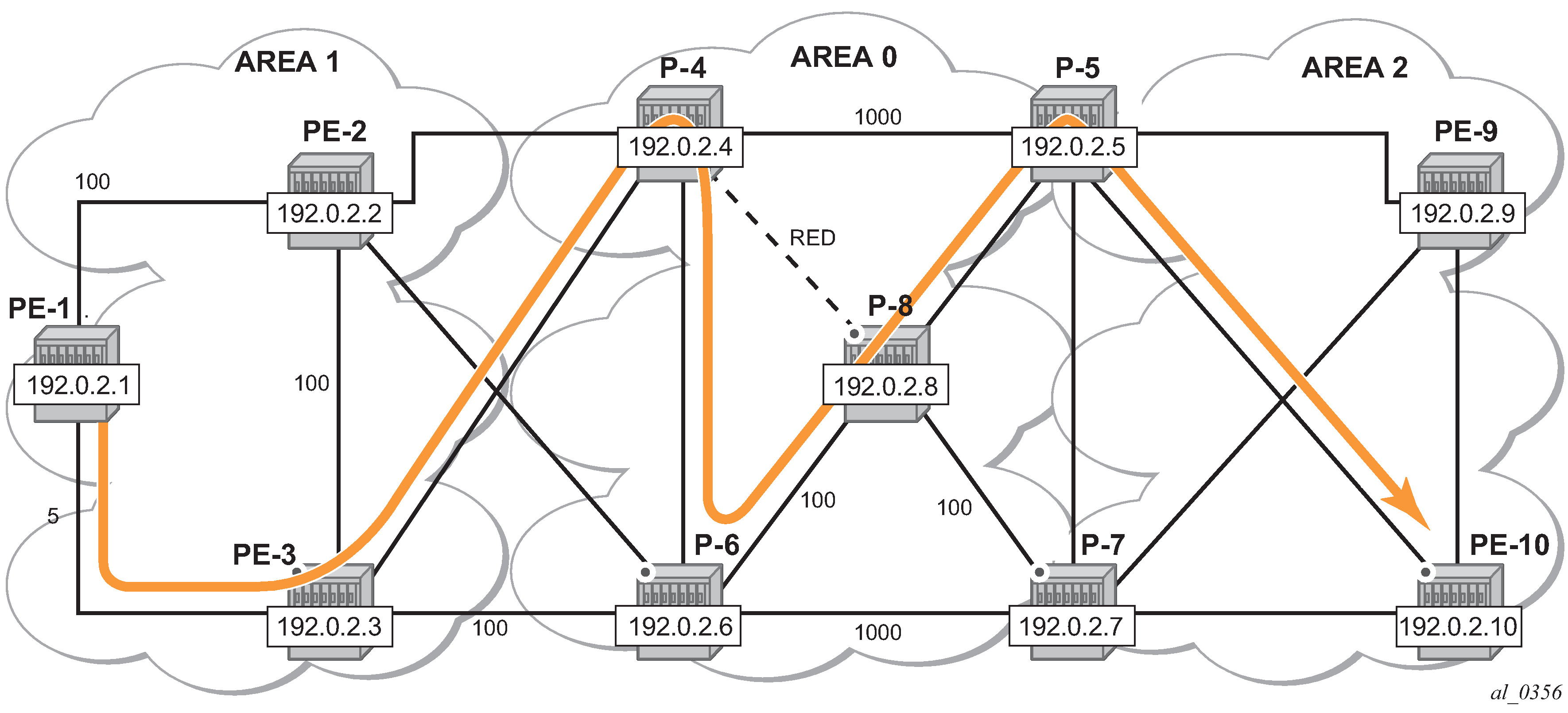
The example topology in this chapter contains ten nodes in three areas, as shown in Inter-area TE LSP setup.
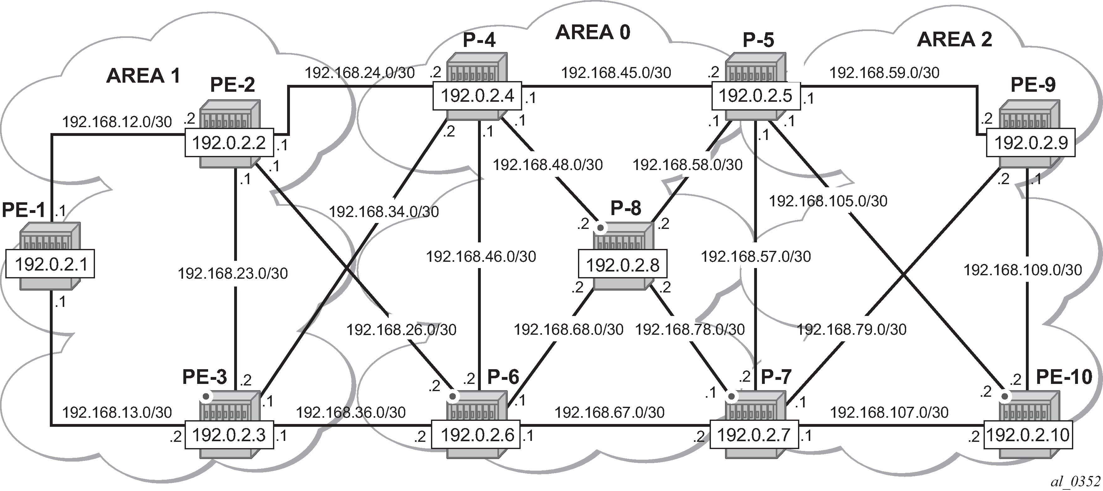
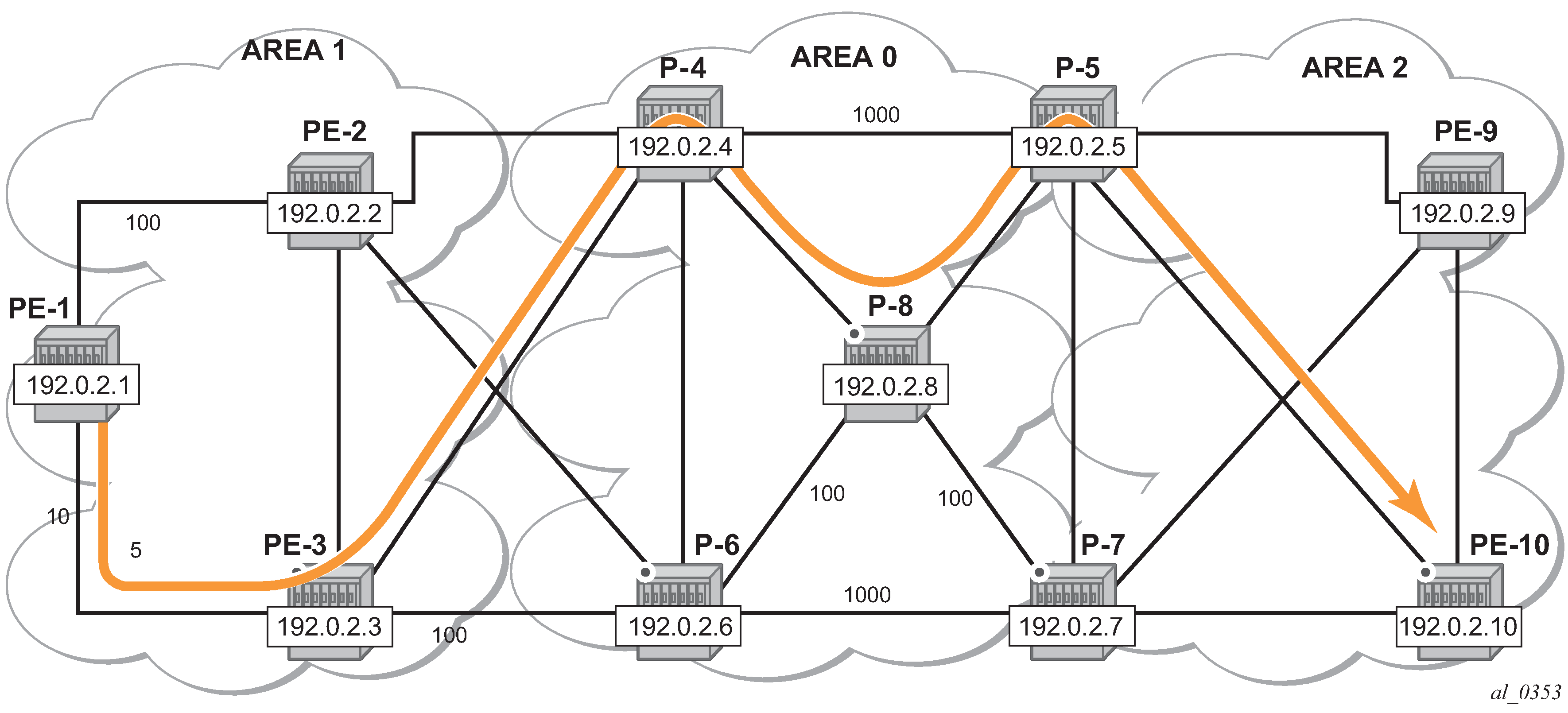
Inter-area TE LSP path shows the LSP path intended to be set up through the network. An empty MPLS path is used. At the head-end node PE-1, the destination address PE-10 is learned via ABR node P-4 and ABR node P-5.
Configuration
The following base configuration has been implemented on the nodes:
Cards, MDAs, and ports configured
Interfaces configured
IGP areas configured and converged
Traffic Engineering configured for the IGP
MPLS and RSVP configured on all links in the network
OSPF or IS-IS can be configured as the IGP; OSPF is used in this chapter.
The following output shows the opaque database of PE-1:
*A:PE-1# show router ospf opaque-database

===============================================================================
Rtr Base OSPFv2 Instance 0 Opaque Link State Database (type: All)
===============================================================================
Type  Id              Link State Id     Adv Rtr Id      Age  Sequence   Cksum
-------------------------------------------------------------------------------
Area  0.0.0.1         1.0.0.1           192.0.2.1       363  0x80000002 0x9234
Area  0.0.0.1         1.0.0.3           192.0.2.1       345  0x80000001 0x9b45
Area  0.0.0.1         1.0.0.4           192.0.2.1       325  0x80000001 0xe9f2
Area  0.0.0.1         1.0.0.1           192.0.2.2       340  0x80000002 0x962e
Area  0.0.0.1         1.0.0.3           192.0.2.2       346  0x80000001 0x7769
Area  0.0.0.1         1.0.0.4           192.0.2.2       325  0x80000001 0x7a4d
Area  0.0.0.1         1.0.0.5           192.0.2.2       305  0x80000001 0xc8fa
Area  0.0.0.1         1.0.0.6           192.0.2.2       262  0x80000001 0x6f4d
Area  0.0.0.1         1.0.0.1           192.0.2.3       320  0x80000002 0x9a28
Area  0.0.0.1         1.0.0.3           192.0.2.3       326  0x80000001 0xb32a
Area  0.0.0.1         1.0.0.4           192.0.2.3       326  0x80000001 0x5671
Area  0.0.0.1         1.0.0.5           192.0.2.3       300  0x80000001 0x5955
Area  0.0.0.1         1.0.0.6           192.0.2.3       261  0x80000001 0xffa7
Area  0.0.0.1         1.0.0.1           192.0.2.4       301  0x80000002 0x9e22
Area  0.0.0.1         1.0.0.6           192.0.2.4       306  0x80000001 0x7e44
Area  0.0.0.1         1.0.0.7           192.0.2.4       306  0x80000001 0x218b
Area  0.0.0.1         1.0.0.1           192.0.2.6       257  0x80000002 0xa616
Area  0.0.0.1         1.0.0.6           192.0.2.6       263  0x80000001 0xf6c5
Area  0.0.0.1         1.0.0.7           192.0.2.6       263  0x80000001 0x990d
-------------------------------------------------------------------------------
No. of Opaque LSAs: 19
===============================================================================
The information is only about routers that are part of area 0.0.0.1. PE-1 cannot calculate an end-to-end CSPF path to node PE-10 because this would require TE topology information from area 0.0.0.0 and area 0.0.0.2.
Each node announces its router ID and each attached link that is part of that area, resulting in 19 opaque LSAs in area 0.0.0.1. The system interfaces of P-4 and P-6 are configured in backbone area 0.0.0.0, not in area 0.0.0.1.
In Inter-area TE LSP path, the LSP passes through node PE-3 and node P-8. To prefer a dynamic path from PE-1 to P-4 via PE-3 rather than via PE-2, it is necessary to configure on PE-1 a lower IGP metric on the interface to PE-3 (the default metric is derived from the interface speed; in this case the metric is 10 by default).
# on PE-1:
configure
    router Base
        ospf 0
            area 0.0.0.1
                interface "int-PE-1-PE-3"
                    metric 5
Similarly, in the core, the IGP metric between P-4 and P-5, and between P-6 and P-7 is increased to force the LSP to pass through the core P-8 node.
# on P-4:
configure
    router Base
        ospf 0
            area 0.0.0.0
                interface "int-P-4-P-5"
                    metric 1000
# on P-6:
configure
    router Base
        ospf 0
            area 0.0.0.0
                interface "int-P-6-P-7"
                    metric 1000
Other metrics have also been manipulated as shown on Inter-area TE LSP path.
MPLS path configuration
An empty MPLS path is sufficient on the head-end node PE-1, because automatic ABR selection is performed. Using an empty MPLS path will ease the provisioning process and brings consistency because this empty MPLS path can be used for both intra and inter-area/level type LSPs.
# on PE-1:
configure
    router Base
        mpls
            path "empty_path"
                no shutdown
MPLS LSP configuration
On PE-1, the following LSP to PE-10 is configured with the previously created MPLS path as primary path. CSPF and fast reroute (FRR) facility are enabled on the LSP.
# on PE-1:
configure
    router Base
        mpls
            lsp "LSP-PE-1-PE-10"
                to 192.0.2.10
                path-computation-method local-cspf
                fast-reroute facility
                exit
                primary "empty_path"
                exit
                no shutdown
            exit
            no shutdown
At this stage, the LSP is in an operational Down state with a failure code of badNode at failure node 192.168.34.2 (ABR P-4), as follows.
*A:PE-1# show router mpls lsp "LSP-PE-1-PE-10" path detail

===============================================================================
MPLS LSP LSP-PE-1-PE-10 Path  (Detail)
===============================================================================
Legend :
    @ - Detour Available              # - Detour In Use
    b - Bandwidth Protected           n - Node Protected
    s - Soft Preemption
    S - Strict                        L - Loose
    A - ABR                           + - Inherited
===============================================================================
-------------------------------------------------------------------------------
LSP LSP-PE-1-PE-10
Path empty_path
-------------------------------------------------------------------------------
LSP Name    : LSP-PE-1-PE-10
From             : 192.0.2.1
To               : 192.0.2.10
Admin State      : Up                      Oper State        : Down
Path Name   : empty_path
Path LSP ID      : 18438                   Path Type         : Primary
Path Admin       : Up                      Path Oper         : Down
Out Interface    : n/a                     Out Label         : n/a
Path Up Time     : 0d 00:00:00             Path Down Time    : 0d 00:01:40
Retry Limit      : 0                       Retry Timer       : 30 sec
Retry Attempt    : 4                       Next Retry In     : 20 sec

BFD Configuration and State
Template         : None                    Ping Interval     : 60
Enable           : False                   State             : notApplicable
WaitForUpTimer   : 4 sec                   OperWaitForUpTimer: N/A
WaitForUpTmLeft  : 0 sec

Adspec           : Disabled                Oper Adspec       : N/A
PathCompMethod   : local-cspf              OperPathCompMethod: N/A
MetricType       : igp                     Oper MetricType   : N/A
Least Fill       : Disabled                Oper LeastFill    : N/A
FRR              : Enabled                 Oper FRR          : N/A
FRR NodeProtect  : Enabled                 Oper FRR NP       : N/A
FR Hop Limit     : 16                      Oper FRHopLimit   : N/A
FR Prop Admin Gr*: Disabled                Oper FRPropAdmGrp : N/A
Propagate Adm Grp: Disabled                Oper Prop Adm Grp : N/A
Inter-area       : N/A

PCE Report       : Disabled+               Oper PCE Report   : Disabled
PCE Control      : Disabled                Oper PCE Control  : Disabled
PCE Update ID    : 0

Neg MTU          : 0                       Oper MTU          : N/A
Bandwidth        : No Reservation          Oper Bandwidth    : N/A
Hop Limit        : 255                     Oper HopLimit     : N/A
Record Route     : Record                  Oper Record Route : N/A
Record Label     : Record                  Oper Record Label : N/A
Setup Priority   : 7                       Oper SetupPriority: N/A
Hold Priority    : 0                       Oper HoldPriority : N/A
Class Type       : 0                       Oper CT           : N/A
Backup CT        : None
MainCT Retry     : Infinite
    Rem          :
MainCT Retry     : 0
    Limit        :
Include Groups   :                         Oper IncludeGroups:
None                                           N/A
Exclude Groups   :                         Oper ExcludeGroups:
None                                           N/A

Adaptive         : Enabled                 Oper Metric       : N/A
Preference       : n/a
Path Trans       : 0                       CSPF Queries      : 4
Failure Code     : badNode
Failure Node : 192.168.34.2
Explicit Hops    :
    No Hops Specified
Actual Hops      :
    No Hops Specified
Computed Hops    :
    No Hops Specified
Resignal Eligible: False
Last Resignal    : n/a                     CSPF Metric       : N/A
===============================================================================
* indicates that the corresponding row element may have been truncated.
To get around the intra-area CSPF confinement, the ERO-expansion feature is enabled on all ABR nodes.
# on P-4, P-5, P-6, P-7:
configure
    router Base
        mpls
            cspf-on-loose-hop
cspf-on-loose-hop is only required if FRR or TE parameters are configured on the LSP. If any of these parameters is configured on the LSP while one of the ABRs along the path is not configured with cspf-on-loose-hop, the LSP will stay operationally down with failure code: badNode and an indication of the interface address of the failure node.
The LSP path can also contain other strict and/or loose hops. However, cspf-on-loose-hop must be configured in the mpls context whenever loose hops are configured in the MPLS path. This command enables ERO expansion and is required for inter-area LSPs on all possible ABR nodes and all nodes not belonging to the area where the iLER is located, which have a loose hop reference in the MPLS path.
On all nodes, debugging is enabled for RSVP PATH messages, as follows:
# on all nodes:
debug
    router "Base"
        rsvp
            packet
                path detail
            exit
        exit
    exit
exit
The following RSVP PATH message on PE-1 shows the ERO calculation on the head-end to the first ABR.
# on PE-1:
1 2021/05/07 17:13:34.540 UTC MINOR: DEBUG #2001 Base RSVP
"RSVP: PATH Msg
Send PATH From:192.0.2.1, To:192.0.2.10
          TTL:255, Checksum:0x7351, Flags:0x0
Session    - EndPt:192.0.2.10, TunnId:1, ExtTunnId:192.0.2.1
SessAttr   - Name:LSP-PE-1-PE-10::empty_path
             SetupPri:7, HoldPri:0, Flags:0x17
RSVPHop    - Ctype:1, Addr:192.168.13.1, LIH:3
TimeValue  - RefreshPeriod:30
SendTempl  - Sender:192.0.2.1, LspId:18468
SendTSpec  - Ctype:QOS, CDR:0.000 bps, PBS:0.000 bps, PDR:infinity
             MPU:20, MTU:1564
LabelReq   - IfType:General, L3ProtID:2048
RRO        - IpAddr:192.168.13.1, Flags:0x0
ERO        - IPv4Prefix 192.168.13.2/32, Strict
             IPv4Prefix 192.168.34.2/32, Strict
             IPv4Prefix 192.0.2.10/32, Loose
FRRObj     - SetupPri:7, HoldPri:0, HopLimit:16, BW:0.000 bps, Flags:0x2
             ExcAny:0x0, IncAny:0x0, IncAll:0x0
"
On the ABR P-4, the ERO is expanded to include the nodes of area 0.0.0.0 of which P-4 is also part. The RRO contains all the hops the PATH message has passed so far.
# on P-4:
1 2021/05/07 17:13:40.587 UTC MINOR: DEBUG #2001 Base RSVP
"RSVP: PATH Msg
Send PATH From:192.0.2.1, To:192.0.2.10
          TTL:253, Checksum:0x1cd, Flags:0x0
Session    - EndPt:192.0.2.10, TunnId:1, ExtTunnId:192.0.2.1
SessAttr   - Name:LSP-PE-1-PE-10::empty_path
             SetupPri:7, HoldPri:0, Flags:0x17
RSVPHop    - Ctype:1, Addr:192.168.48.1, LIH:4
TimeValue  - RefreshPeriod:30
SendTempl  - Sender:192.0.2.1, LspId:18468
SendTSpec  - Ctype:QOS, CDR:0.000 bps, PBS:0.000 bps, PDR:infinity
             MPU:20, MTU:1564
LabelReq   - IfType:General, L3ProtID:2048
RRO        - IpAddr:192.168.48.1, Flags:0x0
             IpAddr:192.168.34.1, Flags:0x0
             IpAddr:192.168.13.1, Flags:0x0
ERO        - IPv4Prefix 192.168.48.2/32, Strict
             IPv4Prefix 192.168.58.1/32, Strict
             IPv4Prefix 192.0.2.10/32, Loose
FRRObj     - SetupPri:7, HoldPri:0, HopLimit:16, BW:0.000 bps, Flags:0x2
             ExcAny:0x0, IncAny:0x0, IncAll:0x0
"
Finally, the P-5 ABR will expand the ERO to the final destination PE-10:
# on P-5:
1 2021/05/07 17:13:42.805 UTC MINOR: DEBUG #2001 Base RSVP
"RSVP: PATH Msg
Send PATH From:192.0.2.1, To:192.0.2.10
          TTL:251, Checksum:0xaa2a, Flags:0x0
Session    - EndPt:192.0.2.10, TunnId:1, ExtTunnId:192.0.2.1
SessAttr   - Name:LSP-PE-1-PE-10::empty_path
             SetupPri:7, HoldPri:0, Flags:0x17
RSVPHop    - Ctype:1, Addr:192.168.105.1, LIH:6
TimeValue  - RefreshPeriod:30
SendTempl  - Sender:192.0.2.1, LspId:18468
SendTSpec  - Ctype:QOS, CDR:0.000 bps, PBS:0.000 bps, PDR:infinity
             MPU:20, MTU:1564
LabelReq   - IfType:General, L3ProtID:2048
RRO        - IpAddr:192.168.105.1, Flags:0x0
             IpAddr:192.168.58.2, Flags:0x0
             IpAddr:192.168.48.1, Flags:0x0
             IpAddr:192.168.34.1, Flags:0x0
             IpAddr:192.168.13.1, Flags:0x0
ERO        - IPv4Prefix 192.168.105.2/32, Strict
FRRObj     - SetupPri:7, HoldPri:0, HopLimit:16, BW:0.000 bps, Flags:0x2
             ExcAny:0x0, IncAny:0x0, IncAll:0x0
"
The MPLS LSP is now operational Up and the LSP path can be shown in detail on the head-end, PE-1:
*A:PE-1# show router mpls lsp "LSP-PE-1-PE-10" path detail

===============================================================================
MPLS LSP LSP-PE-1-PE-10 Path  (Detail)
===============================================================================
Legend :
    @ - Detour Available              # - Detour In Use
    b - Bandwidth Protected           n - Node Protected
    s - Soft Preemption
    S - Strict                        L - Loose
    A - ABR                           + - Inherited
===============================================================================
-------------------------------------------------------------------------------
LSP LSP-PE-1-PE-10
Path empty_path
-------------------------------------------------------------------------------
LSP Name    : LSP-PE-1-PE-10
From             : 192.0.2.1
To               : 192.0.2.10
Admin State      : Up                      Oper State        : Up
Path Name   : empty_path
Path LSP ID      : 18468                   Path Type         : Primary
Path Admin       : Up                      Path Oper         : Up
Out Interface    : 1/1/2                   Out Label         : 524287
Path Up Time     : 0d 00:02:28             Path Down Time    : 0d 00:00:00
Retry Limit      : 0                       Retry Timer       : 30 sec
Retry Attempt    : 0                       Next Retry In     : 0 sec

---snip---

Adspec           : Disabled                Oper Adspec       : Disabled
PathCompMethod   : local-cspf              OperPathCompMethod: local-cspf
MetricType       : igp                     Oper MetricType   : igp
Least Fill       : Disabled                Oper LeastFill    : Disabled
FRR              : Enabled                 Oper FRR          : Enabled
FRR NodeProtect  : Enabled                 Oper FRR NP       : Enabled
FR Hop Limit     : 16                      Oper FRHopLimit   : 16
FR Prop Admin Gr*: Disabled                Oper FRPropAdmGrp : Disabled
Propagate Adm Grp: Disabled                Oper Prop Adm Grp : Disabled
Inter-area       : True

---snip---

Adaptive         : Enabled                 Oper Metric       : 15
Preference       : n/a
Path Trans       : 1                       CSPF Queries      : 19
Failure Code     : noError
Failure Node : n/a
Explicit Hops    :
    No Hops Specified
Actual Hops      :
    192.168.13.1(192.0.2.1) @ n                  Record Label        : N/A
 -> 192.168.13.2(192.0.2.3) @                    Record Label        : 524287
 -> 192.168.34.2(192.0.2.4) @ n                  Record Label        : 524287
 -> 192.168.48.2     @                           Record Label        : 524287
 -> 192.168.58.1     @                           Record Label        : 524287
 -> 192.168.105.2                                Record Label        : 524287
Computed Hops    :
    192.168.13.1(S)
 -> 192.168.13.2(S)
 -> 192.168.34.2(SA)
 -> 192.0.2.10(L)
Resignal Eligible: False
Last Resignal    : n/a                     CSPF Metric       : 15
===============================================================================
* indicates that the corresponding row element may have been truncated.
ABR node protection
The LSP is configured with facility FRR protection; link and node protection are established within each area, as shown in the preceding output. Node protection is available for nodes PE-3 in area 1 (bypass originating in PE-1), and P-8 in area 0 (bypass originating in P-4), but not for the ABRs P-4 and P-5. No bypass tunnels for node protection originate in PLRs PE-3 (for ABR P-4) or P-8 (for ABR P-5). The bypass tunnels originating in PE-3 and P-8 only offer link protection. Dynamic ABR node protection requires the setup of a bypass tunnel from the PLR (node just upstream of the ABR) to the MP (node just downstream of the ABR). The following two things are required to establish a bypass tunnel for an ABR:
The PLR node (part of area x) needs to know the system IP address of the MP node (part of area y) to set up the bypass. For this reason, the node ID of the MP must be included in the RESV message so that the PLR can link the manual bypass tunnel to the primary path to protect the ABR. By default, the node ID is not included in the RESV message, but it can be configured on the MPs as follows: configure router rsvp node-id-in-rro include.
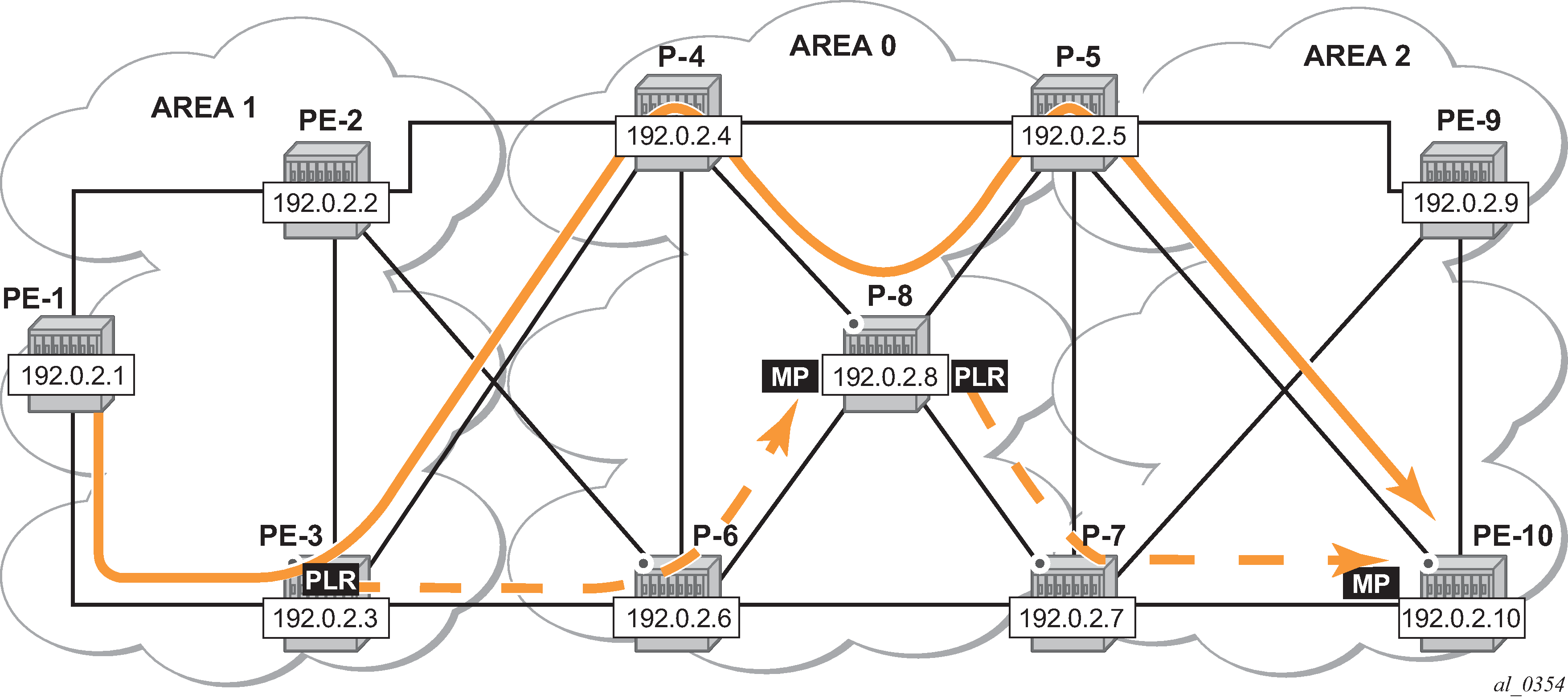
The other ABR node receiving the RSVP bypass PATH message for the protected ABR needs to do an ERO expansion toward the MP node. For this reason, the XRO object is included in the RSVP bypass PATH message, containing the node ID of the protected ABR. As an example, the following bypass PATH message is shown on node PE-3.
The XRO object includes the system IP address of the protected ABR node P-4 and the ERO object has MP node P-8 as loose destination:
# on PE-3:
31 2021/05/07 17:18:47.435 UTC MINOR: DEBUG #2001 Base RSVP
"RSVP: PATH Msg
Send PATH From:192.0.2.3, To:192.0.2.8
          TTL:17, Checksum:0xfddb, Flags:0x0
Session    - EndPt:192.0.2.8, TunnId:61442, ExtTunnId:192.0.2.3
SessAttr   - Name:bypass-node192.0.2.4-61442
             SetupPri:7, HoldPri:0, Flags:0x2
RSVPHop    - Ctype:1, Addr:192.168.36.1, LIH:5
TimeValue  - RefreshPeriod:30
SendTempl  - Sender:192.0.2.3, LspId:4
SendTSpec  - Ctype:QOS, CDR:0.000 bps, PBS:0.000 bps, PDR:infinity
             MPU:20, MTU:1564
LabelReq   - IfType:General, L3ProtID:2048
RRO        - IpAddr:192.168.36.1, Flags:0x0
ERO        - IPv4Prefix 192.168.36.2/32, Strict
             IPv4Prefix 192.0.2.8/32, Loose
XRO        - IPv4Prefix: 192.0.2.4/32, Attribute: Node, LBit: Exclude
AdSpec     - General BreakBit:0, NumISHops:0, PathBwEstimate:0
                     MinPathLatency:4294967295, CompPathMTU:1564
             Controlled BreakBit:0
"
Node-ID inclusion in the RESV message
P-8 will be the MP for the bypass of ABR P-4 and PE-10 will be the MP for the bypass of ABR P-5. So P-8 and PE-10 need to include their node ID in the RESV message, inside the Record Route Object (RRO).
# on P-8 and PE-10:
configure
    router Base
        rsvp
            node-id-in-rro include
The default is node-id-in-rro exclude.
On PE-3, debugging is enabled for RSVP RESV messages, as follows:
# on PE-3:
debug
    router "Base"
        rsvp
            packet
                resv detail
            exit
        exit
The following RESV message is received on PLR node PE-3. The RRO contains the MP node P-8 information in SLIL format:
42 2021/05/07 17:20:10.435 UTC MINOR: DEBUG #2001 Base RSVP
"RSVP: RESV Msg
Send RESV From:192.168.13.2, To:192.168.13.1
          TTL:255, Checksum:0x966f, Flags:0x0
Session    - EndPt:192.0.2.10, TunnId:1, ExtTunnId:192.0.2.1
RSVPHop    - Ctype:1, Addr:192.168.13.2, LIH:3
TimeValue  - RefreshPeriod:30
Style      - SE
FlowSpec   - Ctype:QOS, CDR:0.000 bps, PBS:0.000 bps, PDR:infinity
             MPU:20, MTU:1560, RSpecRate:0, RSpecSlack:0
FilterSpec - Sender:192.0.2.1, LspId:18468, Label:524287
RRO        - InterfaceIp:192.168.13.2, Flags:0x9
             Label:524287, Flags:0x1
             InterfaceIp:192.168.34.2, Flags:0x9
             Label:524287, Flags:0x1
             SystemIp:192.0.2.8, Flags:0x29
             Label:524287, Flags:0x1
             InterfaceIp:192.168.48.2, Flags:0x9
             Label:524287, Flags:0x1
             SystemIp:192.0.2.5, Flags:0x21
             Label:524287, Flags:0x1
             InterfaceIp:192.168.58.1, Flags:0x1
             Label:524287, Flags:0x1
             SystemIp:192.0.2.10, Flags:0x20
             Label:524287, Flags:0x1
             InterfaceIp:192.168.105.2, Flags:0x0
             Label:524287, Flags:0x1
"
Bypass configuration for ABR protection
Because dynamic ABR protection is supported and used in this example, no explicit Manual Bypass Tunnels (MBTs) are configured to protect the ABRs. Each PLR first checks if an MBT tunnel exists between the PLR and the MP matching the constraints and protecting the ABR. If no MBT is available, the PLR will signal a bypass tunnel in a dynamic way toward the MP node.
ABR protection shows the two dynamic ABR node protections that are signaled for this LSP.
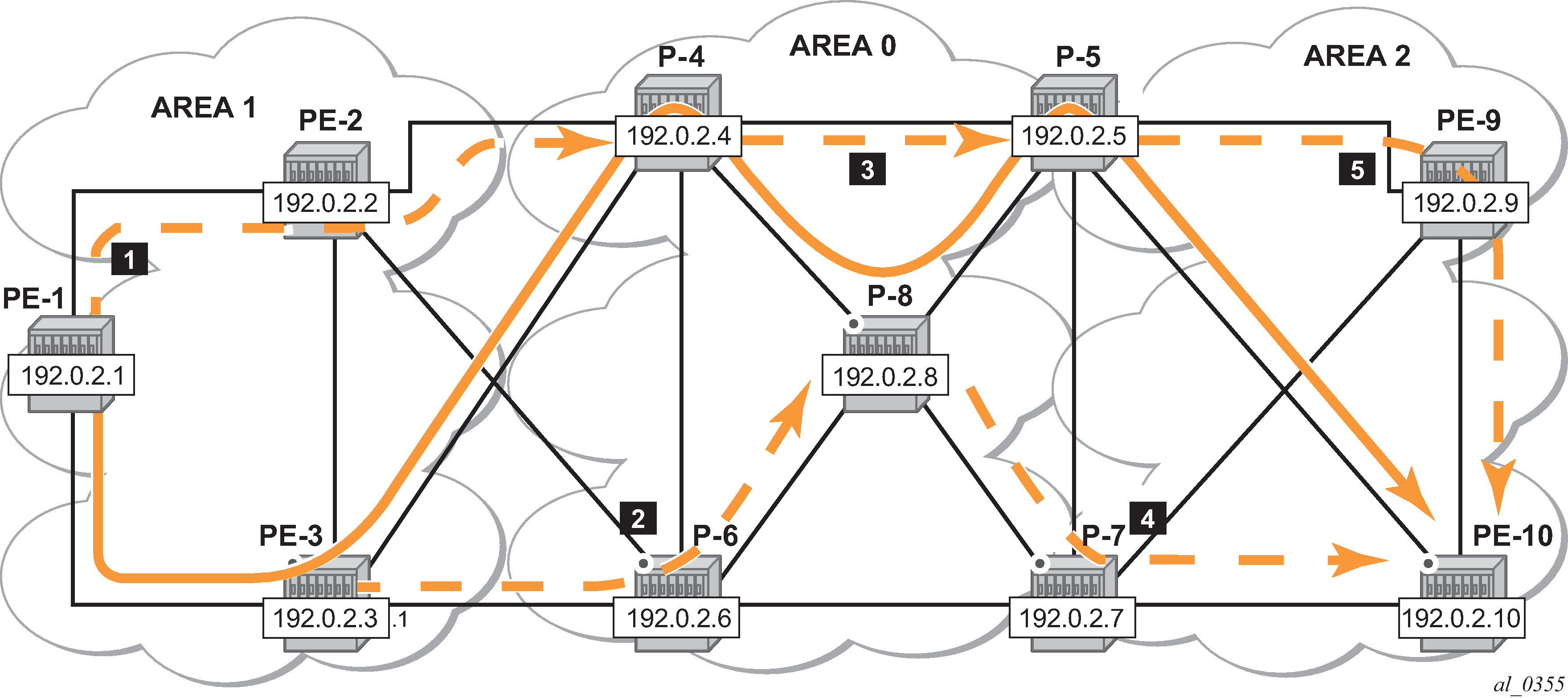
Protection of all nodes/links along the LSP path shows the complete picture of all the FRR protections and indicates each node/link protection in the setup.
This can be seen in the detailed show output of the LSP path:
*A:PE-1# show router mpls lsp "LSP-PE-1-PE-10" path detail

===============================================================================
MPLS LSP LSP-PE-1-PE-10 Path  (Detail)
===============================================================================
Legend :
    @ - Detour Available              # - Detour In Use
    b - Bandwidth Protected           n - Node Protected
    s - Soft Preemption
    S - Strict                        L - Loose
    A - ABR                           + - Inherited
===============================================================================
-------------------------------------------------------------------------------
LSP LSP-PE-1-PE-10
Path empty_path
-------------------------------------------------------------------------------
LSP Name    : LSP-PE-1-PE-10
From             : 192.0.2.1
To               : 192.0.2.10
Admin State      : Up                      Oper State        : Up
Path Name   : empty_path
Path LSP ID      : 18468                   Path Type         : Primary
Path Admin       : Up                      Path Oper         : Up
Out Interface    : 1/1/2                   Out Label         : 524287
Path Up Time     : 0d 00:13:17             Path Down Time    : 0d 00:00:00
Retry Limit      : 0                       Retry Timer       : 30 sec
Retry Attempt    : 0                       Next Retry In     : 0 sec

---snip---

Adspec           : Disabled                Oper Adspec       : Disabled
PathCompMethod   : local-cspf              OperPathCompMethod: local-cspf
MetricType       : igp                     Oper MetricType   : igp
Least Fill       : Disabled                Oper LeastFill    : Disabled
FRR              : Enabled                 Oper FRR          : Enabled
FRR NodeProtect  : Enabled                 Oper FRR NP       : Enabled
FR Hop Limit     : 16                      Oper FRHopLimit   : 16
FR Prop Admin Gr*: Disabled                Oper FRPropAdmGrp : Disabled
Propagate Adm Grp: Disabled                Oper Prop Adm Grp : Disabled
Inter-area       : True

---snip---

Adaptive         : Enabled                 Oper Metric       : 15
Preference       : n/a
Path Trans       : 1                       CSPF Queries      : 19
Failure Code     : noError
Failure Node : n/a
Explicit Hops    :
    No Hops Specified
Actual Hops      :
    192.168.13.1(192.0.2.1) @ n                  Record Label        : N/A
 -> 192.168.13.2(192.0.2.3) @ n                  Record Label        : 524287
 -> 192.168.34.2(192.0.2.4) @ n                  Record Label        : 524287
 -> 192.0.2.8(192.0.2.8) @ n                     Record Label        : 524287
 -> 192.168.48.2     @ n                         Record Label        : 524287
 -> 192.0.2.5(192.0.2.5) @                       Record Label        : 524287
 -> 192.168.58.1     @                           Record Label        : 524287
 -> 192.0.2.10(192.0.2.10)                       Record Label        : 524287
 -> 192.168.105.2                                Record Label        : 524287
Computed Hops    :
    192.168.13.1(S)
 -> 192.168.13.2(S)
 -> 192.168.34.2(SA)
 -> 192.0.2.10(L)
Resignal Eligible: False
Last Resignal    : n/a                     CSPF Metric       : 15
===============================================================================
The first bypass originates in PE-1 and protects node PE-3.
The second bypass originates in PE-3 and protects node P-4.
The third bypass originates in P-4 and protects node P-8.
The fourth bypass originates in P-8 and protects node P-5. There are two entries for P-8: hop 192.0.2.8 and hop 192.168.48.2.
The fifth bypass originates in P-5 and protects the link between P-5 and PE-10. There are two entries for P-5: hop 192.0.2.5 and hop 192.168.58.1.
There are two entries for P-8, P-5 and PE-10 in the ‛Actual Hops’ section in the previous output: one for the interface IP address and one for the system IP address. This is a consequence of configuring node-id-in-rro include on P-8, P-5, and PE-10.
The node-id-in-rro include command is not mandatory for this example on ABR node P-5, but to be able to cover cases where a new LSP is established in the network and P-5 acts as an MP node while the corresponding PLR node for that new LSP is in another area. This RSVP command can be executed on all possible MP nodes in the network.
The following command shows the details of the bypass tunnel from PE-3 to PE-8, protecting PE-4:
*A:PE-3# show router mpls bypass-tunnel protected-lsp detail

===============================================================================
MPLS Bypass Tunnels (Detail)
===============================================================================
-------------------------------------------------------------------------------
bypass-node192.0.2.4-61442
-------------------------------------------------------------------------------
To             : 192.0.2.8           State               : Up
Out I/F        : 1/1/2               Out Label           : 524287
Up Time        : 0d 00:05:08         Active Time         : n/a
Reserved BW    : 0 Kbps              Protected LSP Count : 1
Type           : Dynamic             Bypass Path Cost    : 100
Setup Priority : 7                   Hold Priority       : 0
Class Type     : 0
Exclude Node   : 192.0.2.4           Inter-Area          : True
Computed Hops  :
    192.168.36.1(S)                  Egress Admin Groups : None
 -> 192.168.36.2(SA)                 Egress Admin Groups : None
 -> 192.0.2.8(L)                     Egress Admin Groups : None
Actual Hops    :
    192.168.36.1(192.0.2.3)          Record Label        : N/A
 -> 192.168.36.2(192.0.2.6)          Record Label        : 524287
 -> 192.0.2.8(192.0.2.8)             Record Label        : 524286
 -> 192.168.68.2                     Record Label        : 524286
Last Resignal  :
Attempted At   : n/a                 Resignal Reason     : n/a
Resignal Status: n/a                 Reason              : n/a

Protected LSPs -
LSP Name       : LSP-PE-1-PE-10::empty_path
From           : 192.0.2.1           To                  : 192.0.2.10
Avoid Node/Hop : 192.0.2.4           Downstream Label    : 524287
Bandwidth      : 0 Kbps

===============================================================================
The LSP could be protected with one or more additional secondary paths, pre-signaled or not, but this is outside the scope of this chapter.
When a link or node failure occurs along the LSP path, FRR protection kicks in and end-to-end path re-optimization is executed: a PATHERR message is forwarded to the head-end. Upon receiving the PATHERR message, the head-end calculates a new path.
Admin groups
The use of administrative groups is described in the RSVP Point-to-Point LSPs chapter.
To support admin groups for inter-area LSPs, the ingress node PE-1 must propagate the admin groups within the Session Attribute object (SA) of the PATH message so that the ABRs along the path receive the admin group restrictions they have to take into account when further expanding the ERO in the PATH message.
In Protection of all nodes/links along the LSP path the LSP path avoids the link between P-4 and P-8. This is implemented by assigning admin group ‟red” to the link between P-4 and P-8 and then configuring the LSP to exclude the admin group ‟red”.
Admin group configuration
On P-4, configure admin group ‟red” and assign a group value. In this example, group value 11 is used, but this can be any value between 0 and 31. Assign admin group ‟red” to the link to P-8.
This admin group configuration is required on P-4 and on iLER PE-1. However, it is good practice to configure the admin group on all the nodes.
# on all nodes:
configure
    router Base
        if-attribute
            admin-group "red" value 11
# on P-4:
configure
    router Base
        mpls
            interface "int-P-4-P-8"
                admin-group "red"
            exit
On PE-1, change the LSP configuration as follows:
# on PE-1:
configure
    router Base
        mpls
            lsp "LSP-PE-1-PE-10"
                exclude "red"
                propagate-admin-group
            exit
It is possible to have the same admin group constraint applied to the FRR bypass tunnels in the PLRs, but that is not the case here. The bypass tunnels ignore any admin group constraint. The propagate-admin-group command is required to include the admin group properties in the SA object of the PATH message. The admin group value is mapped to a 32-bitmap. In this example, value 11 means that the 12th bit is set, which means in binary 100000000000 or hex 0x800.
# on PE-1:
45 2021/05/07 17:24:49.910 UTC MINOR: DEBUG #2001 Base RSVP
"RSVP: PATH Msg
Send PATH From:192.0.2.1, To:192.0.2.10
          TTL:255, Checksum:0x6b3b, Flags:0x0
Session    - EndPt:192.0.2.10, TunnId:1, ExtTunnId:192.0.2.1
SessAttr   - Name:LSP-PE-1-PE-10::empty_path
             SetupPri:7, HoldPri:0, Flags:0x17
             Ctype:RA, ExcAny:0x800, IncAny:0x0, IncAll:0x0
RSVPHop    - Ctype:1, Addr:192.168.13.1, LIH:3
TimeValue  - RefreshPeriod:30
SendTempl  - Sender:192.0.2.1, LspId:18472
SendTSpec  - Ctype:QOS, CDR:0.000 bps, PBS:0.000 bps, PDR:infinity
             MPU:20, MTU:1564
LabelReq   - IfType:General, L3ProtID:2048
RRO        - IpAddr:192.168.13.1, Flags:0x0
ERO        - IPv4Prefix 192.168.13.2/32, Strict
             IPv4Prefix 192.168.34.2/32, Strict
             IPv4Prefix 192.0.2.10/32, Loose
FRRObj     - SetupPri:7, HoldPri:0, HopLimit:16, BW:0.000 bps, Flags:0x2
             ExcAny:0x0, IncAny:0x0, IncAll:0x0
"
The following two sets of output show that when P-4 expands the ERO it now excludes the link to node P-8 for the path calculation and the path is set up through P-6, P-8 and P-5.
# on P-4:
106 2021/05/07 17:24:49.910 UTC MINOR: DEBUG #2001 Base RSVP
"RSVP: PATH Msg
Send PATH From:192.0.2.1, To:192.0.2.10
          TTL:253, Checksum:0xd9f4, Flags:0x0
Session    - EndPt:192.0.2.10, TunnId:1, ExtTunnId:192.0.2.1
SessAttr   - Name:LSP-PE-1-PE-10::empty_path
             SetupPri:7, HoldPri:0, Flags:0x17
             Ctype:RA, ExcAny:0x800, IncAny:0x0, IncAll:0x0
RSVPHop    - Ctype:1, Addr:192.168.46.1, LIH:3
TimeValue  - RefreshPeriod:30
SendTempl  - Sender:192.0.2.1, LspId:18472
SendTSpec  - Ctype:QOS, CDR:0.000 bps, PBS:0.000 bps, PDR:infinity
             MPU:20, MTU:1564
LabelReq   - IfType:General, L3ProtID:2048
RRO        - IpAddr:192.168.46.1, Flags:0x0
             IpAddr:192.168.34.1, Flags:0x0
             IpAddr:192.168.13.1, Flags:0x0
ERO        - IPv4Prefix 192.168.46.2/32, Strict
             IPv4Prefix 192.168.68.2/32, Strict
             IPv4Prefix 192.168.58.1/32, Strict
             IPv4Prefix 192.0.2.10/32, Loose
FRRObj     - SetupPri:7, HoldPri:0, HopLimit:16, BW:0.000 bps, Flags:0x2
             ExcAny:0x0, IncAny:0x0, IncAll:0x0
"
*A:PE-1# show router mpls lsp "LSP-PE-1-PE-10" path detail

===============================================================================
MPLS LSP LSP-PE-1-PE-10 Path  (Detail)
===============================================================================
Legend :
    @ - Detour Available              # - Detour In Use
    b - Bandwidth Protected           n - Node Protected
    s - Soft Preemption
    S - Strict                        L - Loose
    A - ABR                           + - Inherited
===============================================================================
-------------------------------------------------------------------------------
LSP LSP-PE-1-PE-10
Path empty_path
-------------------------------------------------------------------------------
LSP Name    : LSP-PE-1-PE-10
From             : 192.0.2.1
To               : 192.0.2.10
Admin State      : Up                      Oper State        : Up
Path Name   : empty_path
Path LSP ID      : 18472                   Path Type         : Primary
Path Admin       : Up                      Path Oper         : Up
Out Interface    : 1/1/2                   Out Label         : 524285
Path Up Time     : 0d 00:19:35             Path Down Time    : 0d 00:00:00
Retry Limit      : 0                       Retry Timer       : 30 sec
Retry Attempt    : 0                       Next Retry In     : 0 sec

---snip---

Adspec           : Disabled                Oper Adspec       : Disabled
PathCompMethod   : local-cspf              OperPathCompMethod: local-cspf
MetricType       : igp                     Oper MetricType   : igp
Least Fill       : Disabled                Oper LeastFill    : Disabled
FRR              : Enabled                 Oper FRR          : Enabled
FRR NodeProtect  : Enabled                 Oper FRR NP       : Enabled
FR Hop Limit     : 16                      Oper FRHopLimit   : 16
FR Prop Admin Gr*: Disabled                Oper FRPropAdmGrp : Disabled
Propagate Adm Grp: Enabled                 Oper Prop Adm Grp : Enabled
Inter-area       : True

---snip---

Include Groups   :                         Oper IncludeGroups:
None                                           None
Exclude Groups   :                         Oper ExcludeGroups:
red                                            red

Adaptive         : Enabled                 Oper Metric       : 15
Preference       : n/a
Path Trans       : 2                       CSPF Queries      : 21
Failure Code     : noError
Failure Node : n/a

Explicit Hops    :
    No Hops Specified
Actual Hops      :
    192.168.13.1(192.0.2.1) @ n                  Record Label        : N/A
 -> 192.168.13.2(192.0.2.3) @ n                  Record Label        : 524285
 -> 192.168.34.2(192.0.2.4) @ n                  Record Label        : 524284
 -> 192.168.46.2     @ n                         Record Label        : 524286
 -> 192.0.2.8(192.0.2.8) @ n                     Record Label        : 524284
 -> 192.168.68.2     @ n                         Record Label        : 524284
 -> 192.0.2.5(192.0.2.5) @                       Record Label        : 524284
 -> 192.168.58.1     @                           Record Label        : 524284
 -> 192.0.2.10(192.0.2.10)                       Record Label        : 524283
 -> 192.168.105.2                                Record Label        : 524283
Computed Hops    :
    192.168.13.1(S)
 -> 192.168.13.2(S)
 -> 192.168.34.2(SA)
 -> 192.0.2.10(L)
Resignal Eligible: False
Last Resignal    : n/a                     CSPF Metric       : 15
Last MBB    :
 MBB Type        : ConfigChange            MBB State         : Success
 Ended At        : 05/07/2021 17:24:51     Old Metric        : 15
 Signaled BW     : 0 Mbps
 Fail Code       : noError
===============================================================================
* indicates that the corresponding row element may have been truncated.
Shared Risk Link Groups (SRLG)
Shared risk link groups are described in chapter Shared Risk Link Groups for RSVP-Based LSPs.
SRLGs are also supported in the context of inter-area TE LSPs. SRLGs refer to situations where links in a network share a common fiber (or a common physical attribute). If one link fails, other links in the group may fail as well. Links in the group have fate sharing.
The MPLS TE SRLG feature enhances backup tunnel path selection so that a backup tunnel avoids using links that are in the same SRLG.
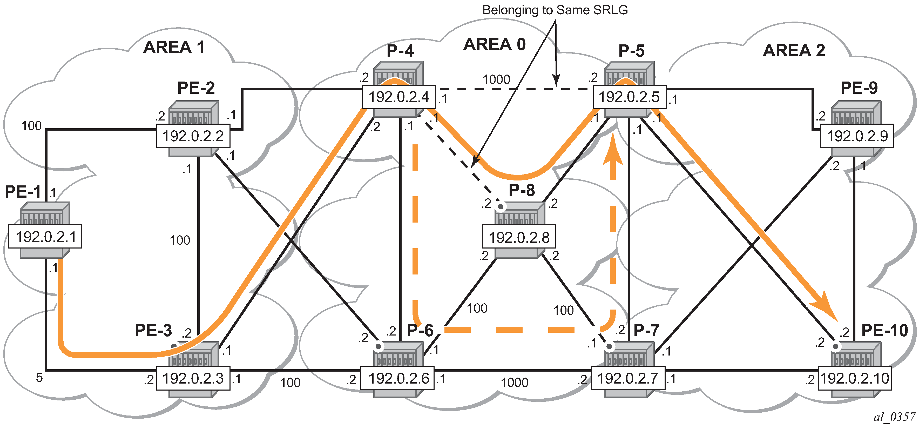
Consider the setup in Share Risk Link Groups, where an inter-area LSP is set up from PE-1 to PE-10 and the path goes through P-8 because of a lower IGP metric. To protect against a node failure of P-8, P-4 (PLR) would normally set up an FRR backup directly to P-5 (MP), because of the lower IGP metric (P-4 to P-5:1000) compared to the IGP traffic via P-6 (P-4 to P-6 to P-7 to P-5:1020).
However, imagine that in this setup the link between P-4 and P-5 and the link between P-4 and P-8 are part of the same transmission bundle. In this case, a cut of that fiber bundle will bring down both the primary and the backup path.
This can be avoided by configuring these two links in the same SRLG group and enabling srlg-frr strict on P-4. In that case, the backup will be set up via P-6 as indicated by the dashed line in Share Risk Link Groups.
SRLG configuration
On P-4, an SRLG group is configured, srlg-frr strict is enabled and the links to P-5 and to P-8 are added to this SRLG group.
The SRLG group configuration is required on all nodes that use SRLG groups and on the ABR used by the inter-area TE LSP. In this example, it is configured on all nodes.
Enabling or disabling srlg-frr command only takes effect when the LSP primary path or the bypass path is resignaled. The user can either wait for the resignal timer to expire or cause the paths to be resignaled immediately by executing, at the ingress LER, the manual resignal command for the LSP primary path or for the bypass LSP path.
# on all nodes:
configure
    router Base
        if-attribute
            srlg-group "bundle-red" value 1
# on P-4:
configure
    router Base
        mpls
            srlg-frr strict
            interface "int-P-4-P-5"
                srlg-group "bundle-red"
            exit
            interface "int-P-4-P-8"
                srlg-group "bundle-red"
            exit
Bounce RSVP to ensure that the srlg-frr command takes effect:
*A:PE-1# configure router rsvp shutdown
*A:PE-1# configure router rsvp no shutdown
LSP configuration
Remove the admin group restriction from the LSP.
# on PE-1:
configure
    router Base
        mpls
            lsp "LSP-PE-1-PE-10"
                no exclude "red"
                no propagate-admin-group
            exit
Now check the LSP path on PE-1 and verify that FRR protection is in place.
*A:PE-1# show router mpls lsp "LSP-PE-1-PE-10" path detail

===============================================================================
MPLS LSP LSP-PE-1-PE-10 Path  (Detail)
===============================================================================
Legend :
    @ - Detour Available              # - Detour In Use
    b - Bandwidth Protected           n - Node Protected
    s - Soft Preemption
    S - Strict                        L - Loose
    A - ABR                           + - Inherited
===============================================================================
-------------------------------------------------------------------------------
LSP LSP-PE-1-PE-10
Path empty_path
-------------------------------------------------------------------------------
LSP Name    : LSP-PE-1-PE-10
From             : 192.0.2.1
To               : 192.0.2.10
Admin State      : Up                      Oper State        : Up
Path Name   : empty_path
Path LSP ID      : 18478                   Path Type         : Primary
Path Admin       : Up                      Path Oper         : Up
Out Interface    : 1/1/2                   Out Label         : 524287
Path Up Time     : 0d 00:01:13             Path Down Time    : 0d 00:00:00
Retry Limit      : 0                       Retry Timer       : 30 sec
Retry Attempt    : 0                       Next Retry In     : 0 sec

---snip---

Adspec           : Disabled                Oper Adspec       : Disabled
PathCompMethod   : local-cspf              OperPathCompMethod: local-cspf
MetricType       : igp                     Oper MetricType   : igp
Least Fill       : Disabled                Oper LeastFill    : Disabled
FRR              : Enabled                 Oper FRR          : Enabled
FRR NodeProtect  : Enabled                 Oper FRR NP       : Enabled
FR Hop Limit     : 16                      Oper FRHopLimit   : 16
FR Prop Admin Gr*: Disabled                Oper FRPropAdmGrp : Disabled
Propagate Adm Grp: Disabled                Oper Prop Adm Grp : Disabled
Inter-area       : True

---snip---

Include Groups   :                         Oper IncludeGroups:
None                                           None
Exclude Groups   :                         Oper ExcludeGroups:
None                                           None

Adaptive         : Enabled                 Oper Metric       : 15
Preference       : n/a
Path Trans       : 4                       CSPF Queries      : 24
Failure Code     : noError
Failure Node : n/a

Explicit Hops    :
    No Hops Specified
Actual Hops      :
    192.168.13.1(192.0.2.1) @ n                  Record Label        : N/A
 -> 192.168.13.2(192.0.2.3) @ n                  Record Label        : 524287
 -> 192.168.34.2(192.0.2.4) @ n                  Record Label        : 524287
 -> 192.0.2.8(192.0.2.8) @ n                     Record Label        : 524287
 -> 192.168.48.2     @ n                         Record Label        : 524287
 -> 192.0.2.5(192.0.2.5) @                       Record Label        : 524287
 -> 192.168.58.1     @                           Record Label        : 524287
 -> 192.0.2.10(192.0.2.10)                       Record Label        : 524287
 -> 192.168.105.2                                Record Label        : 524287
Computed Hops    :
    192.168.13.1(S)
 -> 192.168.13.2(S)
 -> 192.168.34.2(SA)
 -> 192.0.2.10(L)
Resignal Eligible: False
Last Resignal    : n/a                     CSPF Metric       : 15
===============================================================================
On P-4, the SRLG configuration is checked as follows:
*A:P-4# show router if-attribute srlg-group

======================================================================
Interface Srlg Groups
======================================================================
Group Name                       Group Value      Penalty Weight
----------------------------------------------------------------------
bundle-red                       1                0
----------------------------------------------------------------------
No. of Groups: 1
======================================================================
*A:P-4# show router mpls interface

===============================================================================
MPLS Interfaces
===============================================================================
Interface                           Port-id           Adm  Opr(V4/V6) TE-
                                                                      metric
-------------------------------------------------------------------------------
system                              system            Up   Up/Down    None
  Admin Groups                      None
  SRLG Groups                       None
int-P-4-P-5                         1/1/1             Up   Up/Down    None
  Admin Groups                      None
  SRLG Groups                       bundle-red
int-P-4-P-6                         1/1/3             Up   Up/Down    None
  Admin Groups                      None
  SRLG Groups                       None
int-P-4-P-8                         1/2/1             Up   Up/Down    None
  Admin Groups                      red
  SRLG Groups                       bundle-red
int-P-4-PE-2                        1/1/2             Up   Up/Down    None
  Admin Groups                      None
  SRLG Groups                       None
int-P-4-PE-3                        1/1/4             Up   Up/Down    None
  Admin Groups                      None
  SRLG Groups                       None
-------------------------------------------------------------------------------
Interfaces : 6
===============================================================================
On PE-4, it is verified that the bypass tunnel is set up via P-6 rather than via P-5, as follows:
*A:P-4# show router mpls bypass-tunnel protected-lsp detail

===============================================================================
MPLS Bypass Tunnels (Detail)
===============================================================================
-------------------------------------------------------------------------------
bypass-node192.0.2.8-61443
-------------------------------------------------------------------------------
To             : 192.168.57.1        State               : Up
Out I/F        : 1/1/3               Out Label           : 524285
Up Time        : 0d 00:02:23         Active Time         : n/a
Reserved BW    : 0 Kbps              Protected LSP Count : 2
Type           : Dynamic             Bypass Path Cost    : 1020
Setup Priority : 7                   Hold Priority       : 0
Class Type     : 0
Exclude Node   : None                Inter-Area          : False
Computed Hops  :
    192.168.46.1(S)                  Egress Admin Groups : None
 -> 192.168.46.2(S)                  Egress Admin Groups : None
 -> 192.168.67.2(S)                  Egress Admin Groups : None
 -> 192.168.57.1(S)                  Egress Admin Groups : None
Actual Hops    :
    192.168.46.1(192.0.2.4)          Record Label        : N/A
 -> 192.168.46.2(192.0.2.6)          Record Label        : 524285
 -> 192.168.67.2(192.0.2.7)          Record Label        : 524287
 -> 192.168.57.1(192.0.2.5)          Record Label        : 524285
Last Resignal  :
Attempted At   : n/a                 Resignal Reason     : n/a
Resignal Status: n/a                 Reason              : n/a

Protected LSPs -
LSP Name       : LSP-PE-1-PE-10::empty_path
From           : 192.0.2.1           To                  : 192.0.2.10
Avoid Node/Hop : 192.0.2.8           Downstream Label    : 524286
Bandwidth      : 0 Kbps

LSP Name       : LSP-PE-1-PE-10::empty_path
From           : 192.0.2.1           To                  : 192.0.2.10
Avoid Node/Hop : 192.0.2.8           Downstream Label    : 524287
Bandwidth      : 0 Kbps

===============================================================================
Conclusion
Inter-area TE P2P LSPs can be set up based on ERO expansion. With this feature, the head-end does a partial CSPF calculation to its local ABR. On receiving a PATH message with a loose hop ERO, this ABR does a partial or full CSPF calculation to the next ABR to reach the final destination.
FRR protection within the area is available. FRR node protection of the ABR is possible through an MBT on the PLR (node just upstream of the ABR) to the MP (node just downstream of the ABR) or through a dynamically signaled bypass tunnel on the PLR. Dynamic ABR node protection requires that the node ID of the MP node is propagated in the RESV message and that an XRO object is included in the bypass PATH message which makes it possible for the ABR to calculate a path to an MP node.
TE features such as BW, path prioritization, path pre-emption, and graceful shutdown are supported, as well as propagation of the session attribute with affinity along the LSP path (admin groups) and SRLG.