Path MTU Discovery
This chapter provides information about Path MTU discovery.
Topics in this chapter include:
Applicability
This chapter was initially written for SR OS Release 14.0.R7, but the CLI in the current edition corresponds to SR OS Release 21.2.R1.
Overview
The Maximum Transmission Unit (MTU) is the largest packet size (in bytes) that a network can transmit. IP datagrams larger than the MTU are fragmented into smaller packets before being sent. MTU types describes the MTU types that are supported in SR OS at both port and service level.
MTU type |
Description |
|---|---|
Port MTU |
Maximum frame size on a physical wire |
Service MTU |
Maximum end-to-end frame size sent from the customer across an L2 VPN service |
SDP path MTU |
Maximum frame size of encapsulated packets sent over the SDP between service endpoints in IP/MPLS VPN |
VC MTU |
Maximum IP payload size that can be carried inside the tunnel. The VC MTU is derived from the service MTU and negotiated by T-LDP. |
LSP path MTU |
MTU value negotiated by RSVP path/resv messages |
OSPF MTU |
Maximum size of the OSPF packet |
IP MTU |
Used in L3 VPN services (IES or VPRN). Maximum IP packet size that L3 VPN customers can send across the provider network. |
MTU values for Ethernet frames lists the values for the MTU types for Ethernet frames. In SR OS, the MTU value never includes the Frame Check Sequence (FCS).
MTU type |
Value |
|---|---|
Access Port MTU |
Configurable in the port context. Value should be greater than or equal to the sum of the service MTU and the port encapsulation overhead (0 for null, 4 for dot1q, 8 for QinQ). |
Network Port MTU |
Configurable in the port context. Value should be greater than or equal to the sum of the SDP path MTU, the MPLS labels (transport, service, hash (entropy), and OAM labels), and an Ethernet header (possibly with a VLAN tag for dot1q). |
Service MTU |
Configurable in the service context. Maximum payload (IP + Ethernet) that the service offers to the client. Only used in L2 services. |
SDP path MTU |
By default, not configured. Derived from the network port MTU. Should be, at a minimum, the value of the service MTU. Should be, at a maximum, the result of {network port MTU - 2 labels - Ethernet header}. However, the service will become operationally up when the SDP path MTU is higher. The SDP path MTU need not match on both sides of the SDP. |
VC MTU |
Not configurable. Derived from the service MTU and negotiated by T-LDP. The VC MTU value must match the other side. VC MTU = service MTU - 14 bytes (Ethernet header). |
LSP path MTU |
Derived from the port MTU of the network port |
OSPF MTU |
MTU negotiated by OSPF and derived from the port MTU or administratively set |
IP MTU |
Configurable in the L3 routing interfaces |
The values of the first five MTU types listed in Table 2 are important in getting L2 services to an operational state of up. For L3 services, the IP MTU is used instead of the service MTU.
L2 services MTUs for Ethernet frames shows the MTUs used for Ethernet frames in an L2 service, such as an Epipe or a VPLS service.
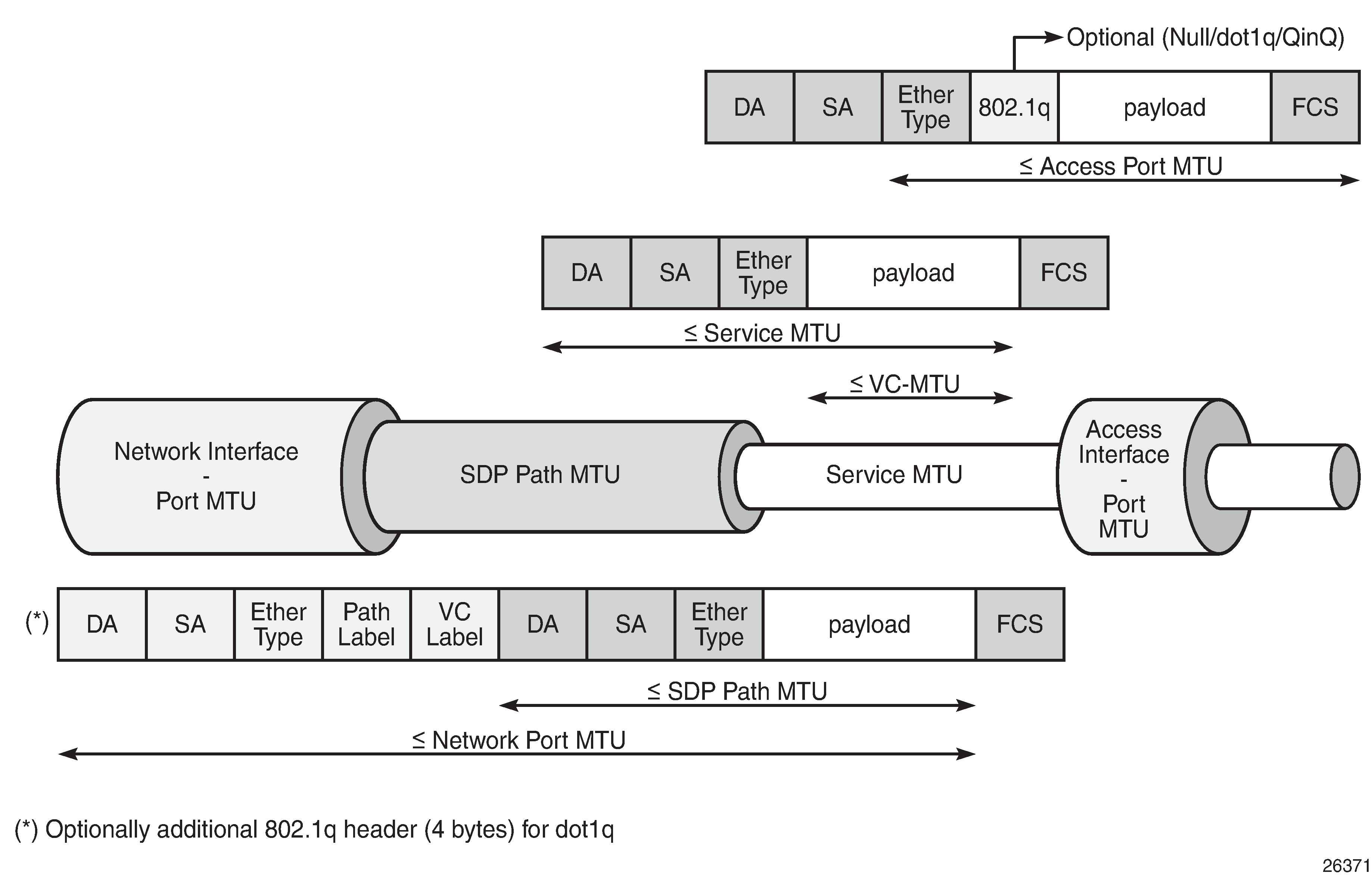
The VC MTU contains the IP payload. The service MTU contains IP payload and Ethernet header. The SDP path MTU must be greater than or equal to the service MTU. Typically, the VLAN tags are stripped at the service ingress, unless VLAN range SAPs are defined and one VLAN tag is preserved. The physical port MTU on an Ethernet access interface needs to be set to at least 1514 for null encapsulation (1500 + 14 (Ethernet header)), at least 1518 for dot1q (1500 + 14 + 4 (dot1q)), and at least 1522 for QinQ (1500 + 14 + 4 + 4).
Minimum network port MTU for Ethernet frames in MPLS encapsulation shows the minimum physical MTU on network interfaces for a router that needs to support services offering a 1514 byte service payload over MPLS for Ethernet.
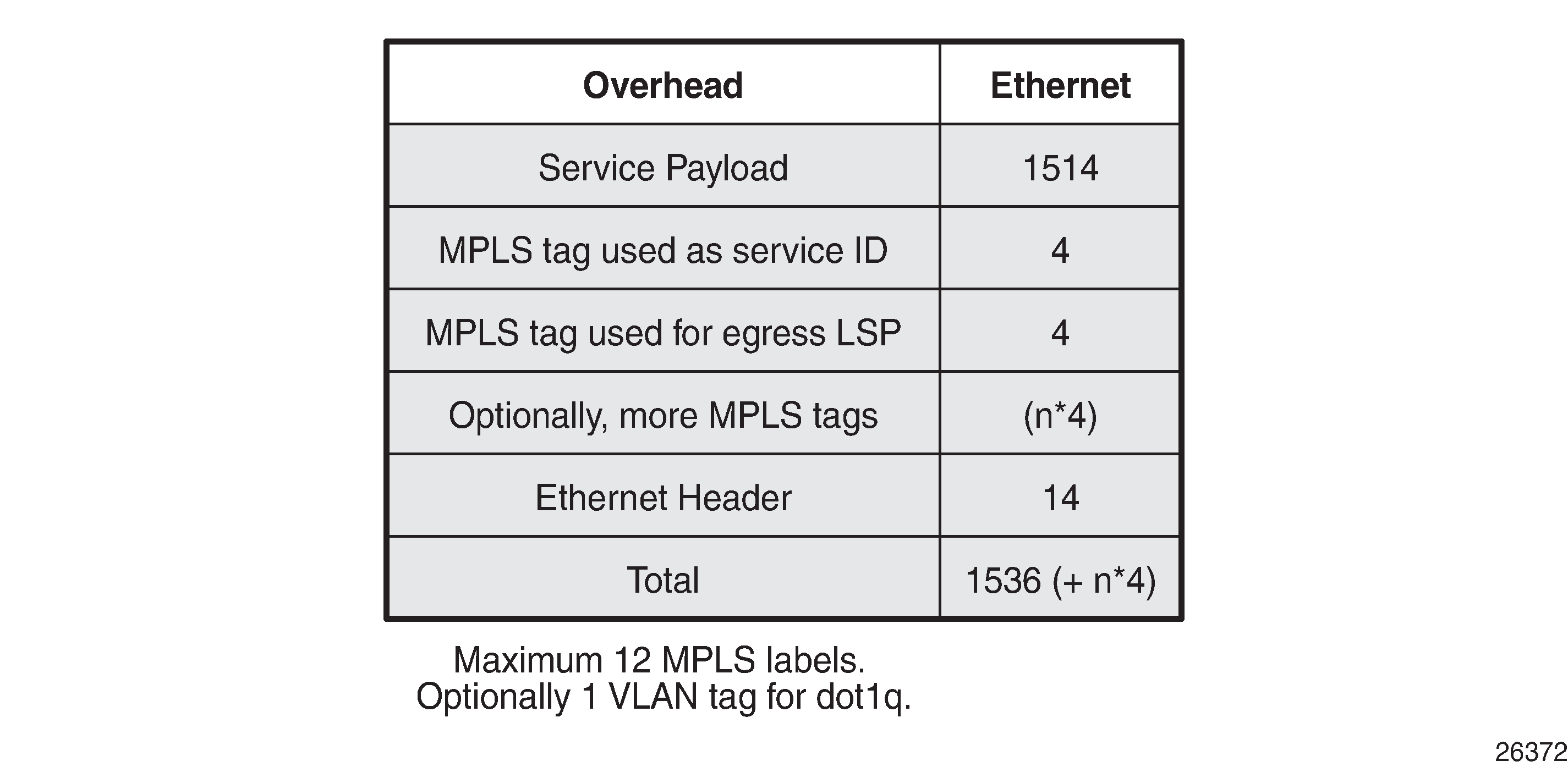
The network port MTU must be at least the maximum service MTU to be supported plus the largest encapsulation type used. The SDP path MTU is at least equal to the service MTU, which is at a minimum 1514 for a service running on a typical Ethernet access interface. This is also valid when the access interface is dot1q or QinQ, because the VLAN tags are stripped at ingress and replaced by the appropriate VLAN tag at egress, unless VLAN range SAPs are defined, in which case one VLAN tag is preserved. The VC tag (service ID) adds a 4 byte service label, the MPLS path adds—at least—one 4 byte transport label, and the Ethernet header adds 14 bytes, for a total of at least 1536 for Ethernet encapsulation. For MPLS, the maximum label stack depth is 12.
The default behavior in SR OS is that the network port MTU is set to its maximum per MDA type, if the network port MTU is not explicitly configured. By default, the SDP path MTU is derived from the network port MTU. For example, when the network port is set to 1600, the SDP path MTU = 1600 (network port MTU) - 4 (MPLS service label) - 4 (MPLS path label) - 14 (Ethernet label) = 1578. However, the SDP path MTU is only accurate when the end-to-end path is considered and the lowest network port MTU in the path is taken.
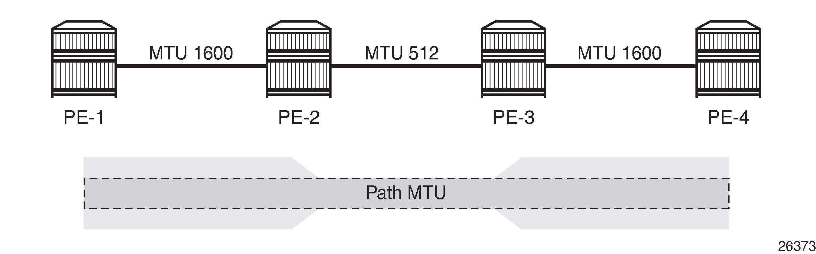
Path MTU shows that the path MTU is determined by the lowest MTU along the path that the service needs to transit. When IP hosts transmit IP datagrams to each other, the path MTU is the largest size for which no fragmentation is required along the path.
Path MTU discovery (PMTUD)
PMTUD is a technique for dynamically discovering the MTU size on the network path between two IP hosts, to maximize packet efficiency and avoid packet fragmentation. PMTUD is standardized in RFC 1191 and for IPv6 in RFC 1981.
PMTUD can be enabled in LDP and BGP in the following contexts:
*A:Dut-A# tree flat detail | match path-mtu-discovery
configure router bgp group neighbor no path-mtu-discovery
configure router bgp group neighbor path-mtu-discovery
configure router bgp group no path-mtu-discovery
configure router bgp group path-mtu-discovery
configure router bgp no path-mtu-discovery
configure router bgp path-mtu-discovery
configure router ldp tcp-session-parameters peer-transport no path-mtu-discovery
configure router ldp tcp-session-parameters peer-transport path-mtu-discovery
configure service vprn bgp group neighbor no path-mtu-discovery
configure service vprn bgp group neighbor path-mtu-discovery
configure service vprn bgp group no path-mtu-discovery
configure service vprn bgp group path-mtu-discovery
configure service vprn bgp no path-mtu-discovery
configure service vprn bgp path-mtu-discovery
PMTUD can be enabled in BGP at different levels: global, per group, or per neighbor. PMTUD can be enabled in BGP in the base router or in a VPRN. For LDP, PMTUD is enabled per peer.
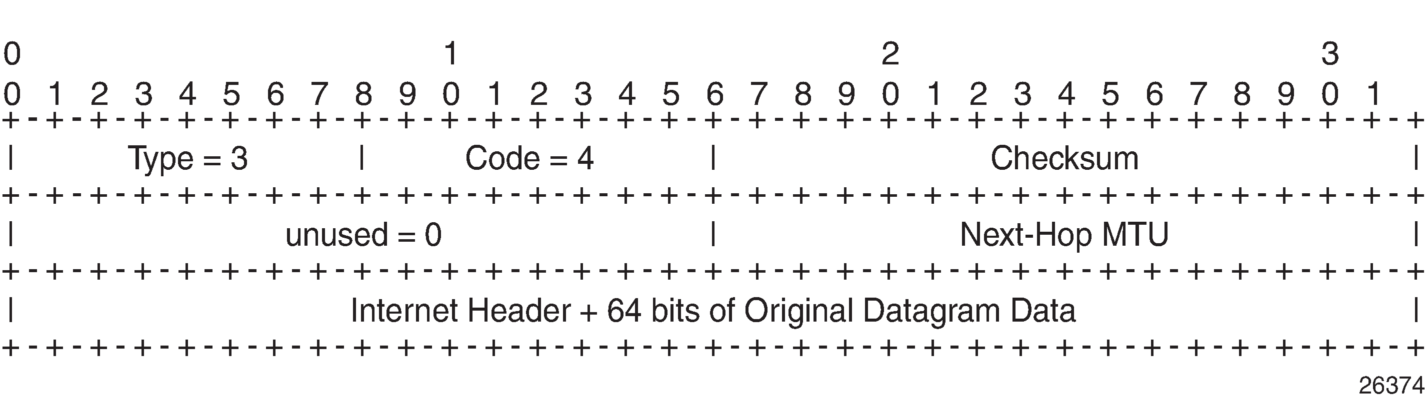
PMTUD works by setting the Don't Fragment (DF) option bit in the IP header of outgoing packets. The source assumes initially that the path MTU is the MTU of its egress interface. Any device along the path with an MTU smaller than the IPv4 packet will drop the packet and notify the source by sending back an Internet Control Message Protocol (ICMP) "Fragmentation Needed" (type 3, code 4) error message containing its MTU. IPv6 packets larger than the MTU will also be dropped in which case an ICMPv6 error message "Packet Too Big" (type 2, code 0) containing its MTU will be sent back. The source can then reduce its path MTU to this received MTU. The process repeats until the MTU is small enough to traverse the entire path without fragmentation.
If the path MTU changes to a lower value after the connection is set up, the first larger packet will cause an ICMP error message and the new, lower path MTU will be determined.
PMTUD is used to determine the most efficient packet size for protocols or applications that may send large packets or large data transfers, including BGP updates, LDP, IGPs, FTP/TFTP/SCP transfers. With PMTUD enabled, each connection can start with the maximum MTU—based on egress MTU—then allow remote and/or transit routers to lower the effective MTU for the session if the current MTU is too large for one of their next hops. The path MTU is handled and tracked on a per session/connection basis.
All routers along the path must be able to send ICMP error messages of type 3 ("Destination Unreachable") and code 4 ("Fragmentation Needed").
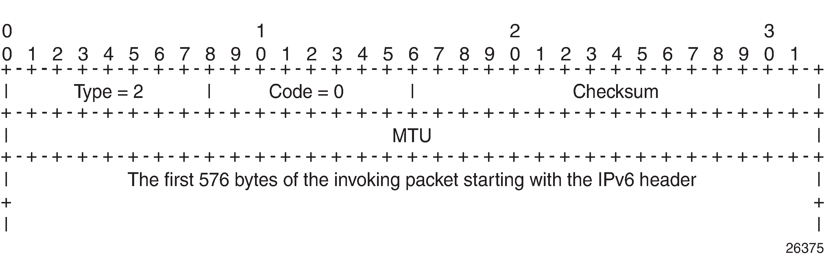
ICMP "Destination Unreachable" Message - Fragmentation Needed shows the format of such an ICMP message. The next hop MTU is the MTU of the egress interface to the destination of the packet on the router that dropped the packet. The MTU is a count of the octets of the IP header and IP data, without lower-level headers.
The mechanism for IPv6 is similar, but the format of the ICMPv6 message is different. For IPv6, the router will send an ICMPv6 error message of type 2 ("Packet Too Big") and code 0, as shown in ICMPv6 "Packet Too Big" message. The MTU field is populated with the MTU of the egress interface to the destination of the packet on the router that dropped the packet. The MTU is a count of the octets of the IP header and IP data, but no lower-level headers.
When PMTUD is enabled, the IP MTU is initially set to the egress MTU size, based on the source IP interface for that session. When a node along the path is unable to forward a packet due to a smaller MTU, the node drops the packet and sends back an ICMP error message with the MTU of the egress interface. The node that receives the ICMP error message will adjust its MTU accordingly. The IP header and the following bytes of the original IP datagram should be used to determine which connection caused the error.
Configuration
The following examples are configured:
PMTUD in LDP for an IPv4 peer
PMTUD in LDP for an IPv6 peer
PMTUD in BGP for an IPv4 peer
PMTUD in BGP for an IPv6 peer
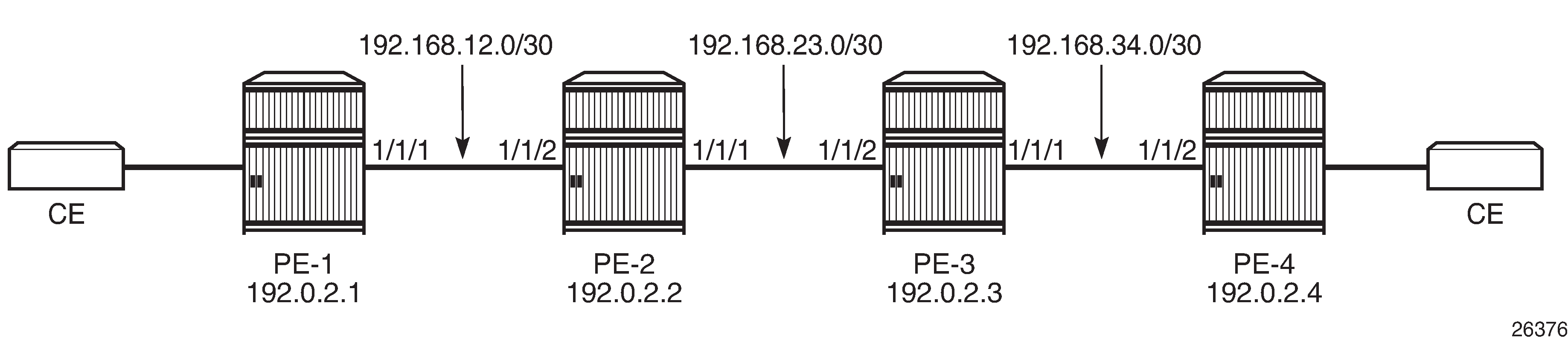
Example topology shows the example topology with four PE nodes in autonomous system 64496. The interfaces have IPv4 and IPv6 addresses, but in this figure, only the IPv4 addresses are shown.
The initial configuration on the nodes includes:
Cards, MDAs, ports
Router interfaces with IPv4 and IPv6 address
IS-IS as IGP on all interfaces between the PEs (alternatively, OSPF can be used)
LDP enabled on all interfaces between the PEs for IPv4 and IPv6
The initial configuration on PE-1 is as follows:
# on PE-1:
configure
    router
        interface "int-PE-1-PE-2"
            address 192.168.12.1/30
            port 1/1/1
            ipv6
                address 2001:db8:12::/127
            exit
        exit
        interface "system"
            address 192.0.2.1/32
            ipv6
                address 2001:db8::1/128
            exit
        exit
        isis
            area-id 49.0001
            ipv6-routing native
            interface "system"
            exit
            interface "int-PE-1-PE-2"
                interface-type point-to-point
            exit
            no shutdown
        exit
        ldp
            interface-parameters
                interface int-PE-1-PE-2 dual-stack
                    ipv4
                        no shutdown
                    exit
                    ipv6
                        no shutdown
                    exit
                exit
            exit
        exit
        exit all
The configuration is similar on the other PEs.
In the example, the default service MTU is used (= 1514 bytes), the access port MTU is 1518 (dot1q encapsulation), and a network port MTU (1600) is set, high enough to support the service MTU (1514):
*A:PE-1# show port

===============================================================================
Ports on Slot 1
===============================================================================
Port          Admin Link Port    Cfg  Oper LAG/ Port Port Port   C/QS/S/XFP/
Id            State      State   MTU  MTU  Bndl Mode Encp Type   MDIMDX
-------------------------------------------------------------------------------
1/1/1         Up    Yes  Up      1600 1600    - netw null xgige  10GBASE-LR  *
1/1/2         Down  No   Down    1578 1578    - netw null xgige  10GBASE-LR  *
1/1/3         Down  No   Down    1578 1578    - netw null xgige  10GBASE-LR  *
1/1/4         Down  No   Down    1578 1578    - netw null xgige  10GBASE-LR  *
1/1/5         Down  No   Down    1578 1578    - netw null xgige  10GBASE-LR  *
1/1/6         Down  No   Down    1578 1578    - netw null xgige  10GBASE-LR  *
1/1/7         Down  No   Down    1578 1578    - netw null xgige  10GBASE-LR  *
1/1/8         Down  No   Down    1578 1578    - netw null xgige  10GBASE-LR  *
1/1/9         Down  No   Down    1578 1578    - netw null xgige  10GBASE-LR  *
1/1/10        Down  No   Down    1578 1578    - netw null xgige  10GBASE-LR  *
1/2/1         Up    Yes  Up      1518 1518    - accs dotq xgige  10GBASE-LR  *
1/2/2         Up    Yes  Up      1518 1518    - accs dotq xgige  10GBASE-LR  *
1/2/3         Down  No   Down    1578 1578    - netw null xgige  10GBASE-LR  *
1/2/4         Down  No   Down    1578 1578    - netw null xgige  10GBASE-LR  *
1/2/5         Down  No   Down    1578 1578    - netw null xgige  10GBASE-LR  *
1/2/6         Down  No   Down    1578 1578    - netw null xgige  10GBASE-LR  *
1/2/7         Down  No   Down    1578 1578    - netw null xgige  10GBASE-LR  *
1/2/8         Down  No   Down    1578 1578    - netw null xgige  10GBASE-LR  *
1/2/9         Down  No   Down    1578 1578    - netw null xgige  10GBASE-LR  *
1/2/10        Down  No   Down    1578 1578    - netw null xgige  10GBASE-LR  *

===============================================================================
Ports on Slot A
===============================================================================
Port          Admin Link Port    Cfg  Oper LAG/ Port Port Port   C/QS/S/XFP/
Id            State      State   MTU  MTU  Bndl Mode Encp Type   MDIMDX
-------------------------------------------------------------------------------
A/1           Up    Yes  Up      1514 1514    - netw null faste  MDI
A/3           Down  No   Down    1514 1514    - netw null faste
A/4           Down  No   Down    1514 1514    - netw null faste

===============================================================================
Ports on Slot B
===============================================================================
Port          Admin Link Port    Cfg  Oper LAG/ Port Port Port   C/QS/S/XFP/
Id            State      State   MTU  MTU  Bndl Mode Encp Type   MDIMDX
-------------------------------------------------------------------------------
B/1           Up    No   Ghost   1514 1514    - netw null faste
B/3           Down  No   Ghost   1514 1514    - netw null faste
B/4           Down  No   Ghost   1514 1514    - netw null faste
===============================================================================
The network port MTU on the link between PE-2 and PE-3 is configured to 512 for IPv4. For IPv6, this network port MTU on the link between PE-2 and PE-3 is reconfigured with a value of 1300.
The service MTU is 1514, the SAP MTU is 1518 (dot1q encapsulation on access port), and the SDP MTU is 1578 (= 1600 (network port MTU) - 14 (Ethernet) - 8 (2 MPLS labels: service label and transport label)), as shown for an Epipe service on PE-1. The configuration for SDP 14 is shown in section SDP path MTU for IPv4; for Epipe_100_name, in section PMTUD for LDP IPv4. This SDP MTU does not consider the lowest network port MTU in the path, but only the local network MTU.
*A:PE-1# show service id 100 base

===============================================================================
Service Basic Information
===============================================================================
Service Id        : 100                 Vpn Id            : 0
Service Type      : Epipe
MACSec enabled    : no
Name              : Epipe_100_name
Description       : (Not Specified)
Customer Id       : 1                   Creation Origin   : manual
Last Status Change: 08/05/2021 11:23:08
Last Mgmt Change  : 08/05/2021 11:21:48
Test Service      : No
Admin State       : Up                  Oper State        : Up
MTU               : 1514
Vc Switching      : False
SAP Count         : 1                   SDP Bind Count    : 1
Per Svc Hashing   : Disabled
Vxlan Src Tep Ip  : N/A
Force QTag Fwd    : Disabled
Oper Group        : <none>

-------------------------------------------------------------------------------
Service Access & Destination Points
-------------------------------------------------------------------------------
Identifier                               Type         AdmMTU  OprMTU  Adm  Opr
-------------------------------------------------------------------------------
sap:1/2/1:100                            q-tag        1518    1518    Up   Up
sdp:14:100 S(192.0.2.4)                  Spok         0       1578    Up   Up
===============================================================================
SDP path MTU for IPv4
The network port MTU is configured to 512 on the interfaces between PE-2 and PE-3, as follows:
# on PE-2:
configure
    port 1/1/1
        ethernet
            mtu 512
            exit all
# on PE-3:
configure
    port 1/1/2
        ethernet
            mtu 512
            exit all
On PE-1, SDP 14 is configured toward PE-4, as follows:
# on PE-1:
configure
    service
        sdp 14 mpls create
            far-end 192.0.2.4
            ldp
            no shutdown
        exit
        exit all
The configuration is similar on PE-4, but with a far end of 192.0.2.1 instead.
The SDP path MTU is derived from the lowest network port MTU in the path: 512 - 14 (Ethernet header) - 4 (MPLS service label) - 4 (MPLS path label) = 490. This can be verified on PE-1 for the end-to-end path with the following OAM command that sends packets with an incrementing size: from 400 to 500 bytes in steps of 10 bytes. The packet with size 490 bytes gets a response, whereas the packet with size 500 gets a timeout.
*A:PE-1# oam sdp-mtu 14 size-inc 400 500 step 10
Size    Sent    Response
----------------------------
400     .       Success
410     .       Success
420     .       Success
430     .       Success
440     .       Success
450     .       Success
460     .       Success
470     .       Success
480     .       Success
490     .       Success
500     ...     Request Timeout

Maximum Response Size: 490
The next step is to repeat the OAM command to send packets with incrementing size from 490 to 500 in steps of 1:
*A:PE-1# oam sdp-mtu 14 size-inc 490 500 step 1
Size    Sent    Response
----------------------------
490     .       Success
491     ...     Request Timeout

Maximum Response Size: 490
The SDP path MTU is 490 bytes.
PMTUD for LDP IPv4
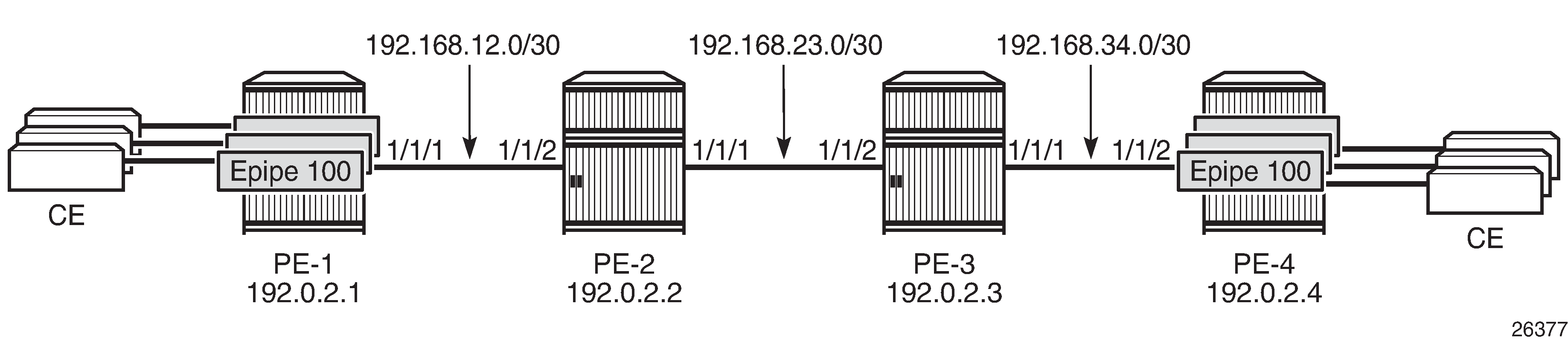
Multiple Epipes Using LDP SDPs shows that multiple Epipe services are configured on PE-1 and PE-4.
The following multiple Epipes are configured on PE-1:
# on PE-1:
configure
    service
        epipe 100 name "Epipe_100_name" customer 1 create
            sap 1/2/1:100 create
            exit
            spoke-sdp 14:100 create
            exit
            no shutdown
        exit
        epipe 101 name "Epipe_101_name" customer 1 create
            sap 1/2/1:101 create
            exit
            spoke-sdp 14:101 create
            exit
            no shutdown
        exit
        ---snip--- for 102 through 108
        epipe 109 name "Epipe_109_name" customer 1 create
            sap 1/2/1:109 create
            exit
            spoke-sdp 14:109 create
            exit
            no shutdown
        exit
        exit all
The following configuration enables PMTUD for LDP IPv4 peer 192.0.2.4 on PE-1. The configuration is similar on PE-4.
# on PE-1:
configure
    router
        ldp
            tcp-session-parameters
                peer-transport 192.0.2.4
                    path-mtu-discovery
                exit
            exit
            exit all
*A:PE-1# show router ldp tcp-session-parameters ipv4

===============================================================================
LDP IPv4 TCP Session Parameters
===============================================================================
-------------------------------------------------------------------------------
Peer Transport: 192.0.2.4
-------------------------------------------------------------------------------
Authentication Key : Disabled           Path MTU Discovery : Enabled
Auth key chain     :                    Min-TTL            : 0
===============================================================================
No. of IPv4 Peers: 1
===============================================================================
When LDP is disabled and re-enabled on PE-1, all label mappings are signaled again.
# on PE-1:
configure
    router
        ldp
            shutdown
            no shutdown
        exit all
The size of the LDP label mapping messages may exceed the MTU between PE-2 and PE-3. The DF bit is set, so the packet is discarded at the egress of PE-2 to PE-3. PE-2 sends an ICMP error message of type 3 and code 4 to PE-1. The following ICMP error message is received on PE-1 when debugging is enabled for ICMP:
# on PE-1:
debug
    router
        ip
            icmp
        exit all
*A:PE-1# show log log-id 2

===============================================================================
Event Log 2 log-name 2
===============================================================================
Description : (Not Specified)
Memory Log contents  [size=100   next event=2  (not wrapped)]

2 2021/08/05 11:36:58.453 UTC MINOR: DEBUG #2001 Base PIP
"PIP: ICMP
instance 1 (Base), interface index 2 (int-PE-1-PE-2),
ICMP  ingressing on int-PE-1-PE-2:
   192.168.23.1 -> 192.0.2.1
type: Destination Unreachable (3)  code: Fragmentation Needed and Don't Fragment was Set (4)
"
---snip---
On the egress interface "int-PE-2-PE-3" on PE-2, the network MTU is 512, the IP MTU is 498 (= 512 - 14 (Ethernet header)), and the TCP Maximum Segment Size (OperMss) is 458 (= 498 - 20 (IP header) - 20 (TCP header)), as shown on PE-1:
*A:PE-1# show system connections port 646

===============================================================================
Connections
===============================================================================
Prot   RecvQ   TxmtQ Local Address                                   State
     RcvdMss OperMss Remote Address                                      vRtrID
-------------------------------------------------------------------------------
TCP        0       0 192.0.2.1.646                                   LISTEN
           0    1024 0.0.0.0.0                                                1
TCP        0       0 192.0.2.1.646                                   ESTABLISH
        1024    1024 192.0.2.2.50593                                          1
TCP        0       0 192.0.2.1.646                                   ESTABLISH
        1538     458 192.0.2.4.51303                                          1
---snip--- for IPv6 addresses
-------------------------------------------------------------------------------
No. of Connections: 5
===============================================================================
TCP port 646 is used for LDP messages. The LDP TCP session with PE-2 keeps the (default) TCP OperMss value of 1024, whereas the LDP TCP session with PE-4 has a reduced TCP OperMss of 458 octets. PE-1 adapts the TCP OperMss size to 458 and retransmits the LDP mapping messages to PE-4. With TCP OperMss set to 458, no fragmentation is required along the path.
PMTUD for LDP IPv6
Multiple Epipes are configured between PE-1 and PE-4. Multiple Epipes between PE-1 and PE-4 - IPv6 shows the IPv6 addresses used.

The service configuration is the same as the preceding service configuration, but the far end of the SDP is an IPv6 address instead, as follows:
# on PE-1:
configure
    service
        sdp 146 mpls create
            far-end 2001:db8::4
            ldp
            no shutdown
        exit
        exit all
With the configured network MTU of 512 on the link between PE-2 and PE-3, SDP 146 (for IPv6) is operationally down, whereas SDP 14 (for IPv4) is up, as follows:
*A:PE-1# show service sdp

============================================================================
Services: Service Destination Points
============================================================================
SdpId  AdmMTU  OprMTU  Far End          Adm  Opr         Del     LSP   Sig
----------------------------------------------------------------------------
14     0       1578    192.0.2.4        Up   Up          MPLS    L     TLDP
146    0       1578                     Up   Down        MPLS    L     TLDP
                       2001:db8::4
----------------------------------------------------------------------------
Number of SDPs : 2
----------------------------------------------------------------------------
Legend: R = RSVP, L = LDP, B = BGP, M = MPLS-TP, n/a = Not Applicable
        I = SR-ISIS, O = SR-OSPF, T = SR-TE, F = FPE
============================================================================
RFC 2460 IPv6 specification states that links with a configurable MTU should have an MTU of at least 1280 octets; preferably 1500 or greater to accommodate possible tunneling encapsulations without the need for fragmentation.
In this example, the network MTU on the link between PE-2 and PE-3 is configured with a value of 1300 and SDP 146 will then be operationally up.
# on PE-2:
configure
    port 1/1/1
        ethernet
            mtu 1300
            exit all
# on PE-3:
configure
    port 1/1/2
        ethernet
            mtu 1300
            exit all
The SDP path MTU for SDP 146 is 1278 (= 1300 - 14 - 4 - 4). This can be verified on PE-1 with the following OAM command:
*A:PE-1# oam sdp-mtu 146 size-inc 1270 1280 step 1
Size    Sent    Response
----------------------------
1270    .       Success
1271    .       Success
1272    .       Success
1273    .       Success
1274    .       Success
1275    .       Success
1276    .       Success
1277    .       Success
1278    .       Success
1279    ...     Request Timeout

Maximum Response Size: 1278
PMTUD is enabled for LDP IPv6 peer 2001:db8::4 on PE-1, as follows:
# on PE-1:
configure
    router
        ldp
            tcp-session-parameters
                peer-transport  2001:db8::4
                    path-mtu-discovery
                exit
            exit
        exit all
*A:PE-1# show router ldp tcp-session-parameters ipv6

===============================================================================
LDP IPv6 TCP Session Parameters
===============================================================================
-------------------------------------------------------------------------------
Peer Transport: 2001:db8::4
-------------------------------------------------------------------------------
Authentication Key : Disabled           Path MTU Discovery : Enabled
Auth key chain     :                    Min-TTL            : 0
===============================================================================
No. of IPv6 Peers: 1
===============================================================================
With an SDP path MTU of 1280 octets, it is extremely unlikely that LDP packets will exceed this size. An example of an ICMPv6 message that is sent when the packet is too big is shown for BGP in section PMTUD for BGP IPv6.
The TCP OperMss for the IPv6 LDP connection between PE-1 and PE-4 is the default value of 1024 bytes. When the SDP path MTU is big enough for TCP segments with segments of 1024 bytes, the TCP OperMss is set to 1024, unless tcp-mss is configured manually on the IPv6 interfaces. This TCP OperMss value may change after an ICMPv6 "Packet Too Big" message is received on PE-1.
*A:PE-1# show system connections address 2001:db8::4 port 646

===============================================================================
Connections
===============================================================================
Prot   RecvQ   TxmtQ Local Address                                   State
     RcvdMss OperMss Remote Address                                      vRtrID
-------------------------------------------------------------------------------
TCP        0       0 2001:db8::1.646                                 ESTABLISH
        1518    1518 2001:db8::4.51304                                        1
-------------------------------------------------------------------------------
No. of Connections: 1
===============================================================================
PMTUD for BGP IPv4
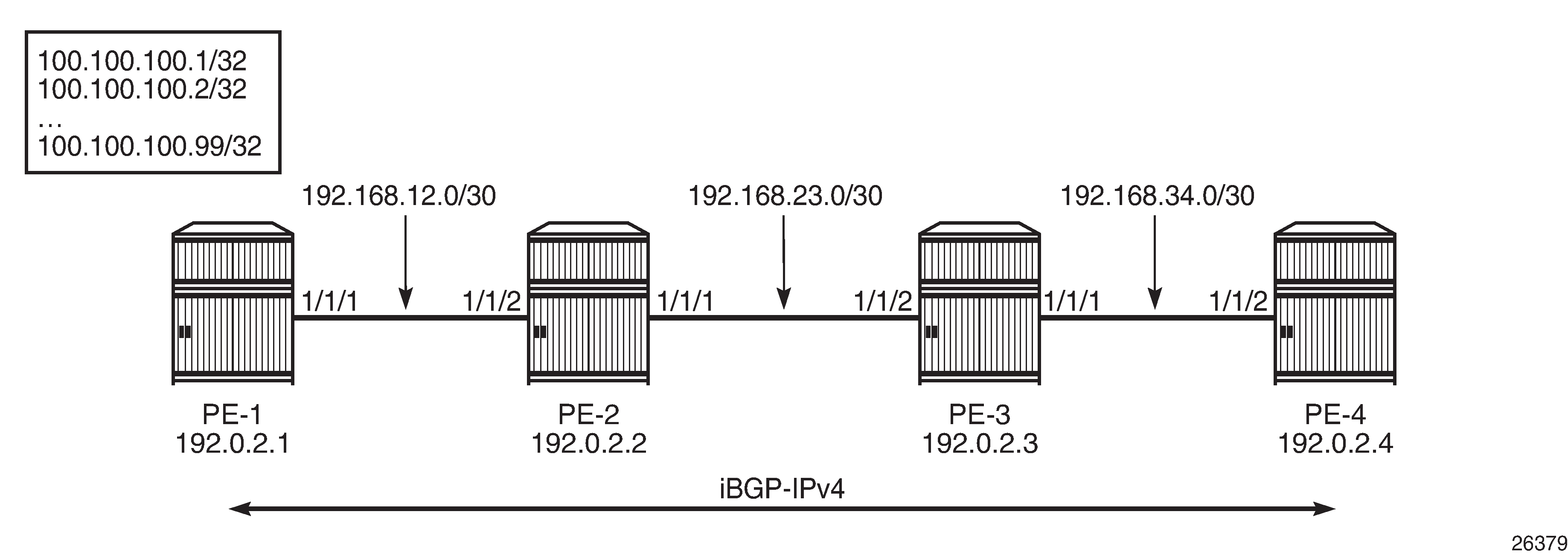
BGP-IPv4 shows that a BGP session is established between PE-1 and PE-4 for address family IPv4. Static routes on PE-1 are exported as BGP routes to PE-4.
The network port MTU on the link between PE-2 and PE-3 is set to 512 again:
# on PE-2:
configure
    port 1/1/1
        ethernet
            mtu 512
            exit all
# on PE-3:
configure
    port 1/1/2
        ethernet
            mtu 512
            exit all
BGP is configured for address family IPv4 on PE-1, as follows:
# on PE-1:
configure
    router
        autonomous-system 64496
        bgp
            group "iBGP_IPv4_name"
                peer-as 64496
                neighbor 192.0.2.4
                    export "export_static_policy"
                    path-mtu-discovery
                exit
            exit
        exit
        policy-options
            begin
            policy-statement "export_static_policy"
                entry 10
                    from
                        protocol static
                    exit
                    action accept
                    exit
                exit
            exit
            commit
        exit all
The export policy exports static routes as BGP routes to neighbor 192.0.2.4. PMTUD can be enabled in the global bgp context, per group, or per neighbor. In this example, PMTUD is enabled for neighbor 192.0.2.4. The configuration on PE-4 is similar, but with a neighbor 192.0.2.1 and without any export policy.
Also, a range of static routes is configured on PE-1 to ensure that the size of the BGP update messages will be larger than the SDP path MTU, as follows:
# on PE-1:
configure
    router
        static-route-entry 100.100.100.1/32 black-hole no shutdown
        static-route-entry 100.100.100.2/32 black-hole no shutdown
        ---snip--- for 3 through 98
        static-route-entry 100.100.100.99/32 black-hole no shutdown
        exit all
Debugging is enabled for ICMP, as follows:
# on PE-1:
clear log 2
no debug
debug
    router
        ip
            icmp
            exit all
BGP is disabled and re-enabled to ensure that all BGP routes are re-advertised to PE-4. The BGP route update messages exceed the MTU on the egress port of PE-2 to PE-3, and PE-2 should have to fragment them to be able to forward them on the egress interface toward PE-3, but the DF bit is set. Therefore, PE-2 discards the packet and sends an ICMP error message to PE-1 of type 3 ("Destination Unreachable") and code 4 ("Fragmentation Needed and Don't Fragment was Set"). PE-1 receives the following ICMP error message:
*A:PE-1# show log log-id 2

===============================================================================
Event Log 2 log-name 2
===============================================================================
Description : (Not Specified)
Memory Log contents  [size=100   next event=2  (not wrapped)]

1 2021/08/05 11:51:59.791 UTC MINOR: DEBUG #2001 Base PIP
"PIP: ICMP
instance 1 (Base), interface index 2 (int-PE-1-PE-2),
ICMP  ingressing on int-PE-1-PE-2:
   192.168.23.1 -> 192.0.2.1
type: Destination Unreachable (3)  code: Fragmentation Needed and Don't Fragment was Set (4)
"
The following output shows that the TCP OperMss for the BGP connection between PE-1 and PE-4 is 458. TCP destination port 179 is used for BGP traffic.
*A:PE-1# show system connections port 179

===============================================================================
Connections
===============================================================================
Prot   RecvQ   TxmtQ Local Address                                   State
     RcvdMss OperMss Remote Address                                      vRtrID
-------------------------------------------------------------------------------
TCP        0       0 0.0.0.0.179                                     LISTEN
           0    1024 0.0.0.0.0                                                1
TCP        0       0 192.0.2.1.49923                                 ESTABLISH
        1538     458 192.0.2.4.179                                            1
TCP        0       0 ::.179                                          LISTEN
           0    1024 ::.0                                                     1
-------------------------------------------------------------------------------
No. of Connections: 3
===============================================================================
The TCP OperMss is calculated as follows: 512 - 14 - 20 - 20 = 458, where 512 is the lowest network port MTU in the path, 14 bytes are used for the Ethernet header, 20 bytes for the IPv4 header, and 20 bytes for the TCP header.
PMTUD for BGP IPv6
BGP-IPv6 shows that a BGP session is established between PE-1 and PE-4 for address family IPv6. PE-1 exports a range of IPv6 routes to PE-4.
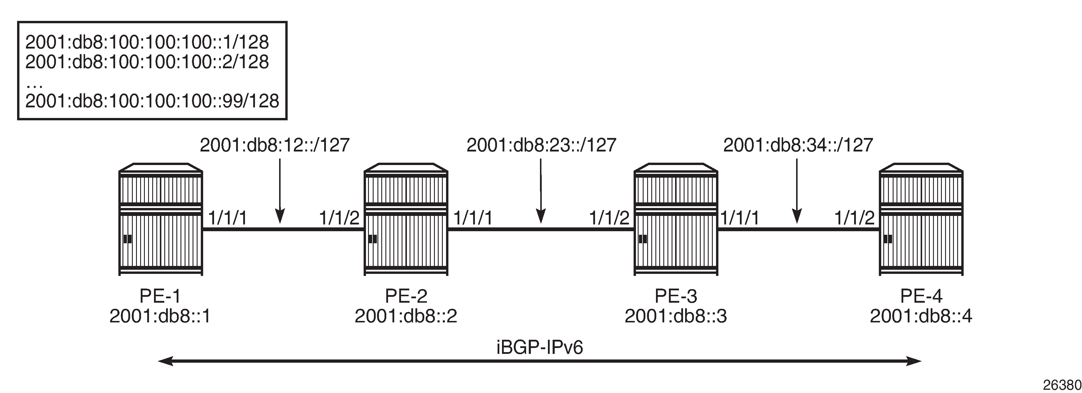
The network port MTU on the link between PE-2 and PE-3 is set to 1300 again:
# on PE-2:
configure
    port 1/1/1
        ethernet
            mtu 1300
            exit all
# on PE-3:
configure
    port 1/1/2
        ethernet
            mtu 1300
            exit all
The BGP configuration is similar for IPv6 to the configuration for IPv4, only the BGP address family and the neighbor addresses are different. The export policy is identical. PMTUD is enabled in the BGP group "iBGP_IPv6_group". The static routes have now IPv6 addresses.
# on PE-1:
configure
    router
        autonomous-system 64496
        policy-options
            begin
            policy-statement "export_static_policy"
                entry 10
                    from
                        protocol static
                    exit
                    action accept
                    exit
                exit
            exit
            commit
        exit
        bgp
            group "iBGP_IPv6_name"
                family ipv6
                peer-as 64496
                path-mtu-discovery
                neighbor 2001:db8::4
                    export "export_static_policy"
                exit
            exit
        exit
        static-route-entry 2001:db8:100:100:100::1/128 black-hole no shutdown
        static-route-entry 2001:db8:100:100:100::2/128 black-hole no shutdown
        ---snip--- for 3 through 80
        static-route-entry 2001:db8:100:100:100::81/128 black-hole no shutdown
## The trick is to have BGP packets that will not be fragmented at the source PE-1!
## When you have 99 routes, the BGP part contains 1700 bytes and will be fragmented by PE-1.
        exit all
The configuration on PE-4 resembles this configuration, but with a different neighbor address. When the group "iBGP_IPv6_group" is disabled and re-enabled, PE-1 advertises all the IPv6 routes to its peer 2001:db8::4. PE-2 cannot forward the large BGP messages and discards them. PE-2 sends an ICMPv6 error message to PE-1 indicating that the packet is too big (type 2, code 0). PE-1 receives the following ICMPv6 error message:
# on PE-1:
clear log 2
no debug
debug
    router "Base"
        ip
            icmp6
            exit all
*A:PE-1# show log log-id 2

===============================================================================
Event Log 2 log-name 2
===============================================================================
Description : (Not Specified)
Memory Log contents  [size=100   next event=10  (not wrapped)]

---snip---
5 2021/08/05 11:57:35.790 UTC MINOR: DEBUG #2001 Base TIP
"TIP: ICMP6_PKT
ICMP6 ingressing on int-PE-1-PE-2 (Base):
   2001:db8:23:: -> 2001:db8::1
Type: Packet Too Big (2)
Code: No Code (0)
MTU : 1286
"
---snip---
The MTU is 1286 and includes the IP header and the IP data, but not the Ethernet header. The calculation is as follows: 1300 - 14 = 1286, where 1300 is the lowest network port MTU in the path and 14 bytes are used for the Ethernet header.
On PE-1, the TCP OperMss for BGP traffic with destination address 2001:db8::4 is 1226, as follows:
*A:PE-1# show system connections port 179

===============================================================================
Connections
===============================================================================
Prot   RecvQ   TxmtQ Local Address                                   State
     RcvdMss OperMss Remote Address                                      vRtrID
-------------------------------------------------------------------------------
TCP        0       0 0.0.0.0.179                                     LISTEN
           0    1024 0.0.0.0.0                                                1
TCP        0       0 192.0.2.1.49923                                 ESTABLISH
        1538     458 192.0.2.4.179                                            1
TCP        0       0 ::.179                                          LISTEN
           0    1024 ::.0                                                     1
TCP        0       0 2001:db8::1.49926                               ESTABLISH
        1518    1226 2001:db8::4.179                                          1
-------------------------------------------------------------------------------
No. of Connections: 4
===============================================================================
The TCP OperMss is calculated as follows: 1300 - 14 - 40 - 20 = 1226, where 1300 is the lowest network port MTU in the path, 14 bytes are used for the Ethernet header, 40 bytes for the IPv6 header, and 20 bytes for the TCP header. This TCP OperMss value is larger than the default value of 1024, so the ICMPv6 "Packet Too Big" message can result in a larger TCP OperMss value.
Conclusion
PMTUD is a technique to determine the MTU size on the network path between two IP hosts, to maximize packet efficiency and avoid packet fragmentation. PMTUD can be enabled for LDP and BGP connections.