Unnumbered Interfaces in RSVP-TE and LDP
This chapter provides information about unnumbered interfaces in RSVP-TE and LDP.
Topics in this chapter include:
Applicability
This chapter is applicable to SR OS routers and was initially written for SR OS Release 13.0.R7. The CLI in this edition corresponds to SR OS Release 22.10.R3. SR OS supports unnumbered interfaces in RSVP-TE and LDP in SR OS Release 11.0.R1 or later.
Overview
Unnumbered interfaces enable IP processing on a point-to-point (P2P) interface without an explicit IP address. Unnumbered interfaces are supported in ReSource reserVation Protocol with Traffic Engineering (RSVP-TE) and Label Distribution Protocol (LDP).
An unnumbered interface is uniquely identified in the network by the tuple (Router ID, If Index), where the interface index (If Index) is unique on the router. The two endpoints of an unnumbered link exchange the If Index that they assigned to the link.
The (Router ID, If Index) tuple is used by the following:
Intermediate System to Intermediate System (IS-IS) or Open Shortest Path First (OSPF) to advertise link information
RSVP to signal Label Switched Paths (LSPs) over this unnumbered interface
LDP to establish hello adjacencies and resolve Forwarding Equivalence Classes (FECs)
Operations, Administration, and Maintenance (OAM) to send or respond to a Multi-Protocol Label Switching (MPLS) echo request over an unnumbered interface
The unnumbered interface can "borrow" the IP address of another interface on the node.
The borrowed IP address is used exclusively as the source address for IP packets that are originated from the unnumbered interface. The borrowed IP address defaults to the system loopback interface address, but can be changed manually. The borrowed IP address corresponds to the Router ID in the tuple representing the unnumbered interface.
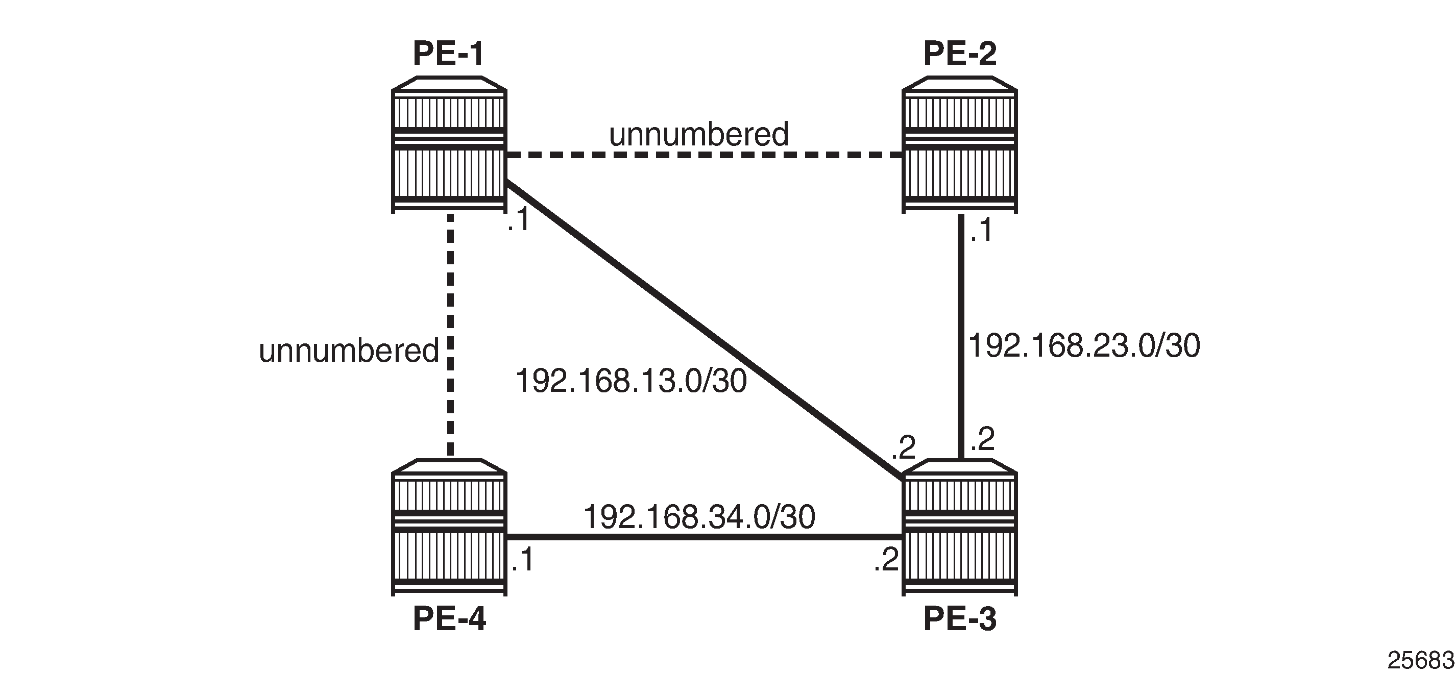
The configuration used in this chapter is shown in Example topology for unnumbered interfaces in RSVP and LDP. There are two unnumbered links: one between PE-1 and PE-2, and another between PE-1 and PE-4. The remaining links are numbered.
Configure unnumbered interfaces as follows:
configure router interface <itf-name> unnumbered [<ip-int-name|ip-address>]
To configure an unnumbered link with the system address as the borrowed IP address, no address needs to be configured:
# on PE-4:
configure
    router
        interface "int-PE-4-PE-1"
            unnumbered
            port 1/1/c1/1
        exit all
An unnumbered interface has to be a P2P link.
Unnumbered interfaces in IS-IS
Unnumbered interfaces are identified in IS-IS by a combination of the system ID and an extended local circuit ID, as described in RFC 5307, IS-IS Extensions in Support of Generalized Multi-Protocol Label Switching (GMPLS).
Enable debugging on the unnumbered interface on PE-4 (int-PE-4-PE-1) as follows:
# on PE-4:
debug
    router
        isis
            packet "int-PE-4-PE-1" detail
        exit all
The following IS-IS hello Protocol Data Unit (PDU) is received from PE-1. The I/F Address is the borrowed IP address; in this case, the system address of PE-1, because the interface is unnumbered.
# on PE-4:
2 2023/03/21 12:42:33.919 UTC MINOR: DEBUG #2001 Base ISIS PKT
"ISIS PKT:
RX ISIS PDU ifId 2 len 52:
  DMAC          : 09:00:2b:00:00:05
  Proto Disc    : 131
  Header Len    : 20
  Version PID   : 1
  ID Length     : 0
  Version       : 1
  Reserved      : 0
  Max Area Addr : 3
  PDU Type      : (11) Point-2-Point IS-IS Hello Pdu
  Circuit Type  : L1
  Source Id     : 19 20 00 00 20 01
  Hold Time     : 27
  Packet length : 52
  Circuit Id    : 0
  Area Addresses:
    Area Address : (3) 49.0001
  Supp Protocols:
    Protocols     : IPv4
  I/F Addresses :
    I/F Address   : 192.0.2.1
  3Way Adjacency   :
    State          : UP
    Ext ckt ID     : 4
    NbrSysID       : 19 20 00 00 20 04
    Nbr ext ckt ID : 2


"
The three-way adjacency contains the neighbor extended local circuit ID (Nbr ext ckt ID: 2). This is the local interface index of the unnumbered interface (int-PE-4-PE-1), which can be verified as follows:
*A:PE-4# show router interface "int-PE-4-PE-1" detail | match "If Index"
If Index         : 2                    Virt. If Index    : 2
Last Oper Chg    : 03/21/2023 12:40:20  Global If Index   : 1
On PE-1, the interface toward PE-4 has a different index, as follows:
*A:PE-1# show router interface "int-PE-1-PE-4" detail | match "If Index"
If Index         : 4                    Virt. If Index    : 4
Last Oper Chg    : 03/21/2023 12:39:43  Global If Index   : 3
For numbered interfaces, such as int-PE-4-PE-3, the I/F Address is the interface address; in that case, 192.168.34.1, for messages received from PE-3 instead of the Router ID.
When a Shared Risk Link Group (SRLG) is configured in combination with IS-IS and unnumbered interfaces, the least significant bit in the flags field of the SRLG Type-Length Value (TLV) indicates that the interface is unnumbered (0) or numbered (1).
Unnumbered interfaces in OSPF
For unnumbered interfaces in OSPF, link local and remote identifiers are defined in RFC 4203, OSPF Extensions in Support of Generalized Multi-Protocol Label Switching (GMPLS). The OSPF link state advertisement (LSA) is defined in RFC 2328, OSPF version 2.
For numbered interfaces, the link data is the IP interface address; for unnumbered interfaces, the link data is the interface index value. The value starts from 1 in the format 0.0.0.1. SR OS recognizes an unnumbered interface when the first byte in the link data has a value of 0; SR OS then treats the link data as an interface index instead of an IP address.
Unnumbered interfaces in RSVP-TE
Unnumbered IP interfaces can be used as Traffic Engineering (TE) links for the signaling of RSVP P2P LSPs and point-to-multipoint (P2MP) LSPs.
Fast Reroute (FRR) facility backup over unnumbered interfaces is supported, whereas FRR one-to-one only uses numbered interfaces in the detour path.
The unnumbered IP address is advertised by IS-IS or OSPF, and Constrained Shortest Path First (CSPF) can include them in the computation of a path.
Unnumbered interfaces of the remote router can be specified in the Explicit Route Object (ERO), and in the Record Route Object (RRO), by a combination of Router ID (borrowed IP address) and interface ID, as defined in RFC 3477, Signalling Unnumbered Links in Resource ReSerVation Protocol - Traffic Engineering (RSVP-TE).
The choice of the data interface is indicated in the Path message by including the interface identifier of the data channel. In the Path message (PATH Msg), the IP address equals the local borrowed IP address; in the Resv message (RESV Msg), the IP address is the remote borrowed IP address. As well as the borrowed IP address, there is also a Logical Interface Handle (LIH). This interface identification is defined in RFC 3473, Generalized Multi-Protocol Label Switching (GMPLS) Signaling Resource ReserVation Protocol-Traffic Engineering (RSVP-TE) Extensions.
To see the Path and Resv messages on PE-4, enter the following debug commands:
# on PE-4:
debug
    router
        rsvp
            packet
                path detail
                resv detail
            exit all
The Path message contains the RSVPHop object with the local interface identifier of the data channel, as follows:
# on PE-4:
19 2023/03/21 13:03:45.671 UTC MINOR: DEBUG #2001 Base RSVP
"RSVP: PATH Msg
Send PATH From:192.0.2.4, To:192.0.2.2
          TTL:255, Checksum:0xa648, Flags:0x0
Session    - EndPt:192.0.2.2, TunnId:1, ExtTunnId:192.0.2.4
SessAttr   - Name:LSP-PE-4-PE-2::dyn
             SetupPri:7, HoldPri:0, Flags:0x17
RSVPHop    - Ctype:3, Addr:192.1.2.4, LIH:2
             RouterId :192.0.2.4, InterfaceId :2
TimeValue  - RefreshPeriod:30
SendTempl  - Sender:192.0.2.4, LspId:2576
SendTSpec  - Ctype:QOS, CDR:0.000 bps, PBS:0.000 bps, PDR:infinity
             MPU:20, MTU:1564
LabelReq   - IfType:General, L3ProtID:2048
RRO        - Unnumbered: RouterId 192.0.2.4 InterfaceID 2, Flags:0x0
ERO        - Unnumbered RouterId 192.0.2.1, LinkId 4, Strict
             Unnumbered RouterId 192.0.2.2, LinkId 2, Strict
FRRObj     - SetupPri:7, HoldPri:0, HopLimit:16, BW:0.000 bps, Flags:0x2
             ExcAny:0x0, IncAny:0x0, IncAll:0x0
"
The ERO and RRO objects are also shown. The unnumbered interfaces are defined by the combination of the Router ID (RouterId) and the interface ID (InterfaceId).
The Resv message also contains the RSVPHop object, but the address is now the remote address of PE-1 instead of the local address of PE-4, as follows:
# on PE-4:
23 2023/03/21 13:04:03.396 UTC MINOR: DEBUG #2001 Base RSVP
"RSVP: RESV Msg
Recv RESV From:192.1.2.1, To:192.0.2.4
          TTL:255, Checksum:0xbe23, Flags:0x0
Session    - EndPt:192.0.2.2, TunnId:1, ExtTunnId:192.0.2.4
RSVPHop    - Ctype:3, Addr:192.1.2.1, LIH:2
             RouterId :192.0.2.1, InterfaceId :4
TimeValue  - RefreshPeriod:30
Style      - SE
FlowSpec   - Ctype:QOS, CDR:0.000 bps, PBS:0.000 bps, PDR:infinity
             MPU:20, MTU:1560, RSpecRate:0, RSpecSlack:0
FilterSpec - Sender:192.0.2.4, LspId:2576, Label:524287
RRO        - Unnumbered: RouterId 192.0.2.1 InterfaceID 4, Flags:0x1
             Label:524287, Flags:0x1
             Unnumbered: RouterId 192.0.2.2 InterfaceID 2, Flags:0x0
             Label:524287, Flags:0x1
"
To see the Patherr (PATHERR Msg) and Resverr (RESVERR Msg) messages on PE-4, enter the following debug command:
# on PE-4:
debug
    router
        rsvp
            packet
                patherr detail
                resverr detail
            exit all
The Resverr message contains the following ErrorSpec object, as defined by RFC 3473. In this case, the error is caused by disabling TE on ingress Label Egress Router (iLER) PE-4. No route can be found to the destination because there is no lookup in the TE database. The LSP does not come up, even if CSPF is disabled on the LSP.
# on PE-4:
32 2023/03/21 13:05:11.398 UTC MINOR: DEBUG #2001 Base RSVP
"RSVP: RESVERR Msg
Send RESVERR From:192.1.2.4, To:192.0.2.1
             TTL:255, Checksum:0x68c1, Flags:0x0
Session    - EndPt:192.0.2.2, TunnId:1, ExtTunnId:192.0.2.4
RSVPHop    - Ctype:3, Addr:192.1.2.4, LIH:2
             RouterId :192.0.2.4, InterfaceId :2
ErrorSpec  - Ctype:3, ErrNode:192.1.2.4, Flags:0x0, ErrCode:3, ErrValue:0
             RouterId :192.0.2.4, InterfaceId :2
Style      - SE
FlowSpec   - Ctype:QOS, CDR:0.000 bps, PBS:0.000 bps, PDR:infinity
             MPU:20, MTU:1560, RSpecRate:0, RSpecSlack:0
FilterSpec - Sender:192.0.2.4, LspId:2576
"
Considerations for unnumbered interfaces in RSVP-TE
Consider the following for unnumbered interfaces in RSVP-TE:
With RSVP, TE must be enabled in IS-IS or OSPF. The Router ID of the router that advertised an unnumbered interface index is obtained from the TE database. Therefore, if TE is disabled in IS-IS or OSPF, a non-CSPF LSP with the next hop for this path over an unnumbered interface does not come up. The Router ID of the neighbor that has the next hop of the Path message cannot be searched for.
The operational state of the LSP path remains down with reason noRouteToDestination.
If a Path message is received at the LSR in which TE is disabled and the next hop for the LSP path is over an unnumbered interface, a Patherr message is sent back to the iLER with error code 24: Routing problem; Error value 5: "No route available toward destination".
Only FRR facility protection is supported; FRR one-to-one protection only works for numbered interfaces.
There is no FRR facility protection if the point of local repair (PLR) is the iLER and the bypass tunnel egress interface is unnumbered.
Bi-directional Forwarding Detection (BFD) can be enabled on an unnumbered router interface. Therefore, RSVP FRR procedures can be triggered via a BFD session timeout.
Unnumbered interfaces cannot be configured as hops in a path. This is true for RSVP-TE LSPs, as well as for static LSPs.
RSVP hello and hello-related capabilities, such as graceful restart helper, are not supported.
SRLG is supported, but the user SRLG DB (user-srlg-db) feature at the iLER is not supported. Unnumbered interfaces cannot be added to the SRLG DB. When the user SRLG DB feature is enabled on the iLER, all unnumbered interfaces are considered as having no SRLG membership.
Unnumbered interfaces in LDP
LDP can establish hello adjacencies and can resolve unicast and multicast FECs over unnumbered interfaces.
For link LDP, hello adjacencies are brought up using hello packets with source IP address set to the borrowed IP address and a destination IP address set to 224.0.0.2. The borrowed IP address is the system address, by default. Hello packets with the same source IP address are accepted when received over parallel unnumbered interfaces from the same peer LSR ID. The corresponding hello adjacencies are associated with a single LDP session.
The transport address for the TCP connection, which is encoded in the hello packet, is always set to the LSR ID of the node. The user can configure the local-lsr-id option on the interface and change the value of the LSR ID to either the local interface or some other interface name: loopback or not, numbered or not. The transport address for the LDP session is updated with the new LSR ID.
For targeted LDP, the source and destination addresses of targeted hello packets are the LDP LSR IDs of the nodes. The user can configure the local-lsr-id option on the targeted session. The transport address for the LDP session and the source IP address of targeted hello messages are updated to the new LSR ID value.
LDP advertises/withdraws unnumbered interfaces using the address/address-withdraw messages. The borrowed IP address of the interface is used.
A FEC can be resolved to an unnumbered interface in the same way as it is resolved to a numbered interface. The outgoing interface and the next hop are searched for in the Routing Table Manager (RTM). The next hop consists of the Router ID and link identifier of the interface to the peer LSR. All LDP FEC types are supported. LDP FEC Equal Cost Multi-Path (ECMP) over a mix of unnumbered and numbered interfaces is supported.
RFC 5036, LDP Specification, describes the address list TLV that is used in the LDP address message, and the LDP address withdrawal message. For unnumbered interfaces, the borrowed IP address is used, which is typically the system address of the sender node.
On PE-1, enable debugging for LDP packets from peer 192.0.2.2 as follows:
# on PE-1:
debug
    router
        ldp
            peer 192.0.2.2
                packet
                    init detail
                    label detail
                exit all
The following LDP address packets are shown at PE-1:
6 2023/03/21 13:23:27.615 UTC MINOR: DEBUG #2001 Base LDP
"LDP: LDP
Send Address packet (msgId 5) to 192.0.2.2:0
Protocol version = 1
Address Family = 1  Number of addresses = 3
Address 1 = 192.0.2.1
Address 2 = 192.1.2.1
Address 3 = 192.168.13.1
"
5 2023/03/21 13:23:27.436 UTC MINOR: DEBUG #2001 Base LDP
"LDP: LDP
Recv Address packet (msgId 5) from 192.0.2.2:0
Protocol version = 1
Address Family = 1  Number of addresses = 3
Address 1 = 192.0.2.2
Address 2 = 192.1.2.2
Address 3 = 192.168.23.1
"
The received LDP address packet contains three IP addresses: the system IP address 192.0.2.2 for an unnumbered interface on the sending node, the loop back IP address 192.1.2.2 for an unnumbered loop back interface on the sending node, and the interface IP address 192.168.23.1 for a numbered interface on the sending node.
Considerations for unnumbered interfaces in LDP
All LDP features are supported on unnumbered interfaces, except for the following:
BFD can be enabled on an unnumbered router interface. The BFD parameters must be configured within the unnumbered interface context. If not, the BFD sessions are not established.
Unnumbered interfaces cannot be added into LDP global and peer prefix policies.
Unnumbered interfaces in OAM
The following applies to unnumbered interfaces in RSVP-TE or LDP.
The downstream mapping object is a TLV that can be included in an echo request, as described in RFC 4379, Detecting Multi-Protocol Label Switched Data Plane Failures.
Only one downstream mapping object may appear in an echo request. The presence of a downstream mapping object is a request that a downstream mapping object be included in the echo reply.
For unnumbered interfaces, the address type is 2 (ipv4Unnumbered), the downstream IP address is the borrowed IP address of the downstream LSR, and the downstream interface address is the index assigned by the upstream LSR to the interface.
The downstream detailed mapping object is a TLV that can be included in an echo request, as described in RFC 6424, Mechanism for Performing Label Switched Path Ping (LSP Ping) over MPLS Tunnels.
The following output shows the detailed LSP trace for an RSVP LSP from PE-4 to PE-2. Two unnumbered interfaces are used: the first between PE-4 and PE-1 and the second between PE-1 and PE-2. The interface type (iftype) is ipv4Unnumbered.
*A:PE-4# oam lsp-trace "LSP-PE-4-PE-2" detail
lsp-trace to LSP-PE-4-PE-2: 0 hops min, 0 hops max, 116 byte packets
0  192.0.2.4
     DS 1: ipaddr=0.0.0.0 iftype=ipv4Unnumbered MRU=1564
           label[1]=524287 protocol=4(RSVP-TE)
1  192.0.2.1  rtt=1.27ms rc=8(DSRtrMatchLabel) rsc=1
     DS 1: ipaddr=0.0.0.0 ifaddr=2 iftype=ipv4Unnumbered MRU=1564
           label[1]=524287 protocol=4(RSVP-TE)
2  192.0.2.2  rtt=1.50ms rc=3(EgressRtr) rsc=1
Configuration
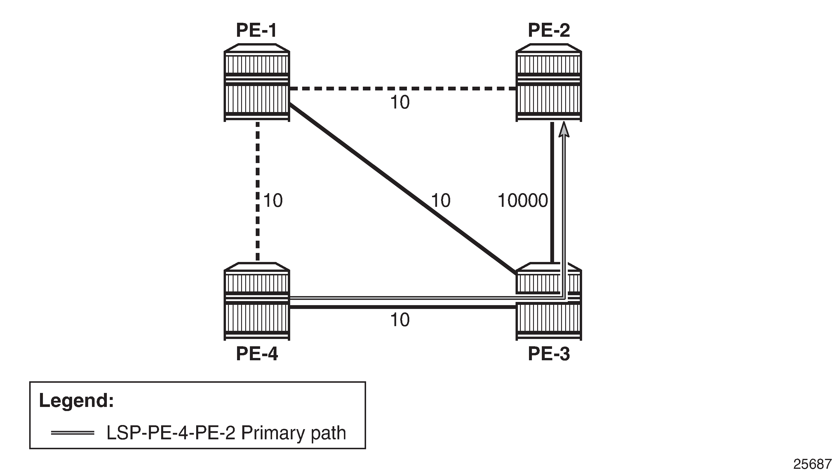
The following configuration example is for unnumbered interfaces in RSVP and LDP; see Configuration example for unnumbered Interfaces in RSVP and LDP. The nodes are 7750 SRs.
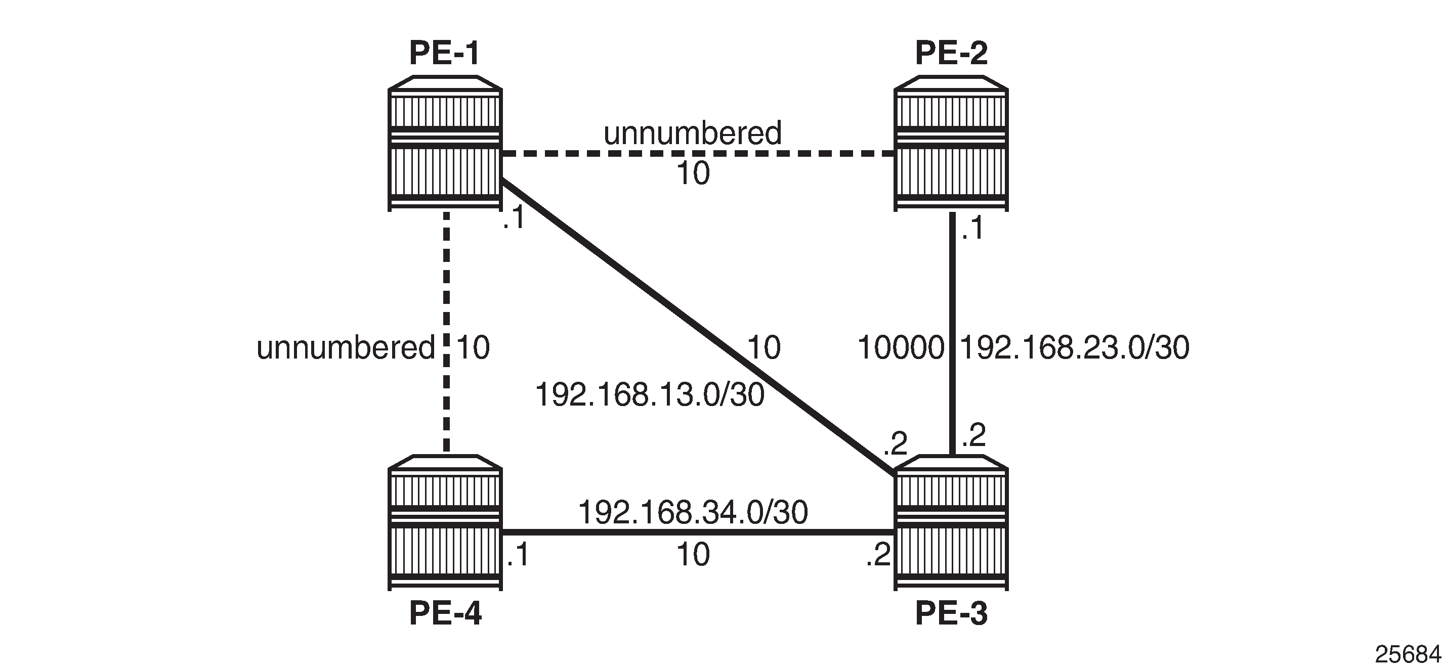
All interfaces have a TE metric of 10, while the link between PE-2 and PE-3 has a TE metric of 10000. So, the preferred path from PE-4 to PE-2 is over the unnumbered interfaces between PE-4 and PE-1 and between PE-1 and PE-2.
Unnumbered interfaces
Router interfaces are configured on all nodes, numbered and unnumbered. Initially, the unnumbered interfaces are configured with default settings. The following interfaces are configured on PE-1:
# on PE-1:
configure
    router
        interface "int-PE-1-PE-2"
            unnumbered
            port 1/1/c1/1
        exit
        interface "int-PE-1-PE-3"
            address 192.168.13.1/30
            port 1/1/c1/3
        exit
        interface "int-PE-1-PE-4"
            unnumbered
            port 1/1/c1/2
        exit
        interface "system"
            address 192.0.2.1/32
        exit
    exit all
There are two unnumbered interfaces: int-PE-1-PE-2 and int-PE-1-PE-4. There is no borrowed IP address configured for the unnumbered interfaces. So, the borrowed IP address is the system address of PE-1.
For the unnumbered interfaces, the borrowed IP address is indicated between square brackets in the following output:
*A:PE-1# show router interface

===============================================================================
Interface Table (Router: Base)
===============================================================================
Interface-Name                   Adm       Opr(v4/v6)  Mode    Port/SapId
   IP-Address                                                  PfxState
-------------------------------------------------------------------------------
int-PE-1-PE-2                    Up        Up/Down     Network 1/1/c1/1
   Unnumbered If[system]                                       n/a
int-PE-1-PE-3                    Up        Up/Down     Network 1/1/c1/3
   192.168.13.1/30                                             n/a
int-PE-1-PE-4                    Up        Up/Down     Network 1/1/c1/2
   Unnumbered If[system]                                       n/a
system                           Up        Up/Down     Network system
   192.0.2.1/32                                                n/a
-------------------------------------------------------------------------------
Interfaces : 4
===============================================================================
Each interface, numbered or unnumbered, gets an interface index. This interface index can be retrieved as follows:
*A:PE-1# show router interface "int-PE-1-PE-2" detail | match "If Index"
If Index         : 2                    Virt. If Index    : 2
Last Oper Chg    : 03/21/2023 12:39:43  Global If Index   : 1

*A:PE-1# show router interface "int-PE-1-PE-3" detail | match "If Index"
If Index         : 3                    Virt. If Index    : 3
Last Oper Chg    : 03/21/2023 12:39:43  Global If Index   : 2

*A:PE-1# show router interface "int-PE-1-PE-4" detail | match "If Index"
If Index         : 4                    Virt. If Index    : 4
Last Oper Chg    : 03/21/2023 12:39:43  Global If Index   : 3

*A:PE-1# show router interface "system" detail | match "If Index"
If Index         : 1                    Virt. If Index    : 1
Last Oper Chg    : 03/21/2023 12:39:43  Global If Index   : 256
The unnumbered interface toward PE-2 has If Index 2, and the unnumbered interface toward PE-4 has If Index 4.
BFD can be enabled on unnumbered interfaces, as follows:
# on PE-4:
configure
    router
        interface "int-PE-4-PE-1"
            port 1/1/c1/1
            unnumbered 192.1.2.4
            bfd 100 receive 100 multiplier 3
            no shutdown
        exit all
The BFD parameters must be configured within the unnumbered interface context. If not, the BFD sessions are not established.
An Interior Gateway Protocol (IGP) must be configured. In this case, IS-IS is chosen. OSPF could have been used equally well. TE must be enabled for unnumbered interfaces used in RSVP, even when CSPF is disabled. The IS-IS configuration on PE-1 is as follows:
# on PE-1:
configure
    router
        isis
            level-capability level-1
            area-id 49.0001
            traffic-engineering
            interface "system"
            exit
            interface "int-PE-1-PE-2"
                interface-type point-to-point
            exit
            interface "int-PE-1-PE-3"
                interface-type point-to-point
            exit
            interface "int-PE-1-PE-4"
                interface-type point-to-point
            exit
            no shutdown
        exit all
An unnumbered interface has to be a P2P link.
The TE database contains the Router ID and the If Index for unnumbered interfaces, as follows:
*A:PE-1# show router isis database PE-2.00-00 detail

===============================================================================
Rtr Base ISIS Instance 0 Database (detail)
===============================================================================

Displaying Level 1 database
-------------------------------------------------------------------------------
LSP ID    : PE-2.00-00                                  Level     : L1
Sequence  : 0x2                    Checksum  : 0x1c5a   Lifetime  : 1080
Version   : 1                      Pkt Type  : 18       Pkt Ver   : 1
Attributes: L1                     Max Area  : 3        Alloc Len : 126
SYS ID    : 1920.0000.2002         SysID Len : 6        Used Len  : 126

TLVs :
  Area Addresses:
    Area Address : (3) 49.0001
  Supp Protocols:
    Protocols     : IPv4
  IS-Hostname   : PE-2
  Router ID   :
    Router ID   : 192.0.2.2
  I/F Addresses :
    I/F Address   : 192.168.23.1
    I/F Address   : 192.0.2.2
  TE IS Nbrs   :
    Nbr   : PE-1.00
    Default Metric  : 10
    Sub TLV Len     : 10
    LclId    : 2
    RmtId    : 2
  TE IS Nbrs   :
    Nbr   : PE-3.00
    Default Metric  : 10000
    Sub TLV Len     : 12
    IF Addr   : 192.168.23.1
    Nbr IP    : 192.168.23.2
---snip---
===============================================================================
PE-2 has an unnumbered interface toward neighbor PE-1 (Nbr: PE-1.00), with local interface index 2 (LclId: 2) and remote interface index 2 (RmtId: 2). For the numbered interface toward neighbor PE-3, the local and remote interface IP addresses are shown (IF Addr and Nbr IP), not the interface index.
Unnumbered interfaces in RSVP
MPLS and RSVP must be enabled on the interfaces on the nodes. TE metrics are configured on the MPLS interfaces. For node PE-4, the configuration is as follows:
# on PE-4:
configure
    router
        mpls
            interface "system"
            exit
            interface "int-PE-4-PE-1"
                te-metric 10
            exit
            interface "int-PE-4-PE-3"
                te-metric 10
            exit
        exit
        rsvp
            no shutdown
        exit
    exit all
An LSP is configured from PE-4 to PE-2 with CSPF enabled and using the TE metrics, not the IGP metrics. Unnumbered interfaces cannot be configured as hops in a path. A dynamic path "dyn", without any hops, is configured to be used in an LSP from PE-4 to PE-2, as follows:
# on PE-4:
configure
    router
        mpls
            path "dyn"
                no shutdown
            exit
            lsp "LSP-PE-4-PE-2"
                to 192.0.2.2
                path-computation-method local-cspf
                metric-type te
                primary "dyn"
                exit
                no shutdown
            exit
            no shutdown
        exit all
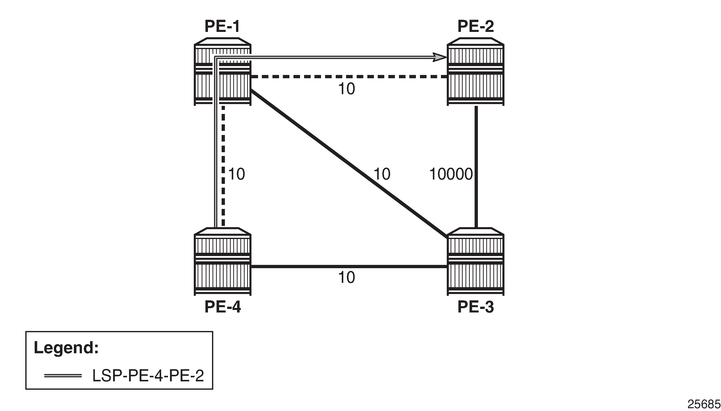
The LSP from PE-4 to PE-2 has TE metric 20 when the next hop is PE-1, and TE metric 30 or 10010 when the next hop is PE-3. LSP-PE-4-PE-2 on unnumbered interfaces shows LSP-PE-4-PE-2, which uses only unnumbered interfaces.
The following tunnel table shows a next hop int-PE-4-PE-1, which implies that it is an unnumbered interface. The only unnumbered interface at PE-4 is int-PE-4-PE-1. The metric in this tunnel table is 16777215 because the IGP metric is not used.
*A:PE-4# show router tunnel-table

===============================================================================
IPv4 Tunnel Table (Router: Base)
===============================================================================
Destination           Owner     Encap TunnelId  Pref   Nexthop        Metric
   Color
-------------------------------------------------------------------------------
192.0.2.2/32          rsvp      MPLS  1         7      int-PE-4-PE-1  16777215
-------------------------------------------------------------------------------
Flags: B = BGP or MPLS backup hop available
       L = Loop-Free Alternate (LFA) hop available
       E = Inactive best-external BGP route
       k = RIB-API or Forwarding Policy backup hop
===============================================================================
The actual and computed hops can be verified, as well as the CSPF metric (TE metric), as follows:
*A:PE-4# show router mpls lsp "LSP-PE-4-PE-2" path detail

===============================================================================
MPLS LSP LSP-PE-4-PE-2 Path  (Detail)
===============================================================================
Legend :
    @ - Detour Available              # - Detour In Use
    b - Bandwidth Protected           n - Node Protected
    s - Soft Preemption
    S - Strict                        L - Loose
    A - ABR                           + - Inherited
===============================================================================
-------------------------------------------------------------------------------
LSP LSP-PE-4-PE-2
Path dyn
-------------------------------------------------------------------------------
LSP Name    : LSP-PE-4-PE-2
From             : 192.0.2.4
To               : 192.0.2.2
Admin State      : Up                      Oper State        : Up
Path Name   : dyn
Path LSP ID      : 2560                    Path Type         : Primary
Path Admin       : Up                      Path Oper         : Up
Out Interface    : 1/1/c1/1                Out Label         : 524287
---snip---
Explicit Hops    :
    No Hops Specified
Actual Hops      :
    192.0.2.4, If Index : 2                      Record Label        : N/A
 -> 192.0.2.1, If Index : 4                      Record Label        : 524287
 -> 192.0.2.2, If Index : 2                      Record Label        : 524287
Computed Hops    :
    192.0.2.4, If Index : 2(S)
 -> 192.0.2.1, If Index : 4(S)
 -> 192.0.2.2, If Index : 2(S)
Resignal Eligible: False
Last Resignal    : n/a                     CSPF Metric       : 20
===============================================================================
The computed hops are strict hops, as indicated by (S). Because the interfaces are unnumbered, the system address and the If Index are displayed. The CSPF metric is 20.
Configuring the borrowed IP address
The borrowed IP address does not need to be the system address, but the address must exist on the node. When the unnumbered interface is configured with a borrowed IP address that does not exist on the node, the interface goes down. This can be verified by assigning a non-existent address to the unnumbered interface int-PE-1-PE-2, as follows:
# on PE-1:
configure
    router
        interface "int-PE-1-PE-2"
            port 1/1/c1/1
            unnumbered 192.1.2.1
        exit all
The operational state of this interface goes down, which can be verified as follows:
*A:PE-1# show router interface

===============================================================================
Interface Table (Router: Base)
===============================================================================
Interface-Name                   Adm       Opr(v4/v6)  Mode    Port/SapId
   IP-Address                                                  PfxState
-------------------------------------------------------------------------------
int-PE-1-PE-2                    Up        Down/Down   Network 1/1/c1/1
   Unnumbered If[192.1.2.1]                                    n/a
int-PE-1-PE-3                    Up        Up/Down     Network 1/1/c1/3
   192.168.13.1/30                                             n/a
int-PE-1-PE-4                    Up        Up/Down     Network 1/1/c1/2
   Unnumbered If[system]                                       n/a
system                           Up        Up/Down     Network system
   192.0.2.1/32                                                n/a
-------------------------------------------------------------------------------
Interfaces : 4
===============================================================================
The borrowed IP address is indicated between square brackets. The interface is down because the IP address is not known on PE-1. The down reason code noIfAddress can be retrieved as follows:
*A:PE-1# show router interface "int-PE-1-PE-2" detail | match "Down Reason Code"
Down Reason Code : noIfAddress
The IP address can be configured as a loopback address on PE-1 and assigned to all unnumbered interfaces, as follows:
# on PE-1:
configure
    router
        interface "loopback1"
            address 192.1.2.1/32
            loopback
        exit
        interface "int-PE-1-PE-2"
            port 1/1/c1/1
            unnumbered 192.1.2.1
        exit
        interface "int-PE-1-PE-4"
            port 1/1/c1/2
            unnumbered 192.1.2.1
        exit
    exit all
When the borrowed IP address is known on node PE-1, the unnumbered interface is operationally up, which can be verified as follows:
*A:PE-1# show router interface

===============================================================================
Interface Table (Router: Base)
===============================================================================
Interface-Name                   Adm       Opr(v4/v6)  Mode    Port/SapId
   IP-Address                                                  PfxState
-------------------------------------------------------------------------------
int-PE-1-PE-2                    Up        Up/Down     Network 1/1/c1/1
   Unnumbered If[192.1.2.1]                                    n/a
int-PE-1-PE-3                    Up        Up/Down     Network 1/1/c1/3
   192.168.13.1/30                                             n/a
int-PE-1-PE-4                    Up        Up/Down     Network 1/1/c1/2
   Unnumbered If[192.1.2.1]                                    n/a
loopback1                        Up        Up/Down     Network loopback
   192.1.2.1/32                                                n/a
system                           Up        Up/Down     Network system
   192.0.2.1/32                                                n/a
-------------------------------------------------------------------------------
Interfaces : 5
===============================================================================
In a similar way, the borrowed IP address on PE-2 is configured as 192.1.2.2 and on PE-4 as 192.1.2.4.
TE required for unnumbered interfaces in RSVP
For unnumbered interfaces, the IGP looks up the Router ID in the TE database. Therefore, TE must be enabled even if CSPF is disabled.
TE is disabled in IS-IS and CSPF is disabled in the LSP on PE-4, as follows:
# on PE-4:
configure
    router
        isis
            no traffic-engineering
        exit
        mpls
            lsp "LSP-PE-4-PE-2"
                shutdown
                no metric-type
                no path-computation-method
                sleep 1
                no shutdown
            exit
        exit
    exit all
LSP-PE-4-PE-2 is operationally down with failure code noRouteToDestination, which can be verified as follows:
*A:PE-4# show router mpls lsp "LSP-PE-4-PE-2" path detail

===============================================================================
MPLS LSP LSP-PE-4-PE-2 Path  (Detail)
===============================================================================
Legend :
    @ - Detour Available              # - Detour In Use
    b - Bandwidth Protected           n - Node Protected
    s - Soft Preemption
    S - Strict                        L - Loose
    A - ABR                           + - Inherited
===============================================================================
-------------------------------------------------------------------------------
LSP LSP-PE-4-PE-2
Path dyn
-------------------------------------------------------------------------------
LSP Name    : LSP-PE-4-PE-2
From             : 192.0.2.4
To               : 192.0.2.2
Admin State      : Up                      Oper State        : Down
Path Name   : dyn
Path LSP ID      : 2566                    Path Type         : Primary
Path Admin       : Up                      Path Oper         : Down
---snip---
MetricType       : igp                     Oper MetricType   : N/A
---snip---
Failure Code     : noRouteToDestination
Failure Node : 192.0.2.4
---snip---
===============================================================================
The configuration is restored by enabling TE in IS-IS and CSPF in the lsp context, as follows:
# on PE-4:
configure
    router
        isis
            traffic-engineering
        exit
        mpls
            lsp "LSP-PE-4-PE-2"
                shutdown
                path-computation-method local-cspf
                metric-type te
                sleep 1
                no shutdown
            exit
        exit
    exit all
FRR facility
FRR facility is enabled on the LSP as follows:
# on PE-4:
configure
    router
        mpls
            lsp "LSP-PE-4-PE-2"
                fast-reroute facility
                exit all
The following LSP path detail output shows where an FRR detour is available (@) and in which node a bypass tunnel originates. The letter n indicates that a node is protected, as in hop 192.0.2.4. When there is a detour available, but there is no n, link protection is available, as in hop 192.0.2.1:
*A:PE-4# show router mpls lsp "LSP-PE-4-PE-2" path detail

===============================================================================
MPLS LSP LSP-PE-4-PE-2 Path  (Detail)
===============================================================================
Legend :
    @ - Detour Available              # - Detour In Use
    b - Bandwidth Protected           n - Node Protected
    s - Soft Preemption
    S - Strict                        L - Loose
    A - ABR                           + - Inherited
===============================================================================
-------------------------------------------------------------------------------
LSP LSP-PE-4-PE-2
Path dyn
-------------------------------------------------------------------------------
LSP Name    : LSP-PE-4-PE-2
From             : 192.0.2.4
To               : 192.0.2.2
Admin State      : Up                      Oper State        : Up
Path Name   : dyn
Path LSP ID      : 2568                    Path Type         : Primary
Path Admin       : Up                      Path Oper         : Up
Out Interface    : 1/1/c1/1                Out Label         : 524286
---snip---
Explicit Hops    :
    No Hops Specified
Actual Hops      :
    192.0.2.4, If Index : 2 @ n                  Record Label        : N/A
 -> 192.0.2.1, If Index : 4 @                    Record Label        : 524286
 -> 192.0.2.2, If Index : 2                      Record Label        : 524286
Computed Hops    :
    192.0.2.4, If Index : 2(S)
 -> 192.0.2.1, If Index : 4(S)
 -> 192.0.2.2, If Index : 2(S)
Resignal Eligible: False
Last Resignal    : n/a                     CSPF Metric       : 20
---snip---
===============================================================================
* indicates that the corresponding row element may have been truncated.
Information about the bypass tunnel originating in PE-4 can be retrieved as follows:
*A:PE-4# show router mpls bypass-tunnel protected-lsp detail

===============================================================================
MPLS Bypass Tunnels (Detail)
===============================================================================
-------------------------------------------------------------------------------
bypass-node192.0.2.1-61441
-------------------------------------------------------------------------------
To             : 192.168.23.1        State               : Up
Out I/F        : 1/1/c1/2            Out Label           : 524286
Up Time        : 0d 00:02:25         Active Time         : n/a
Reserved BW    : 0 Kbps              Protected LSP Count : 1
Type           : Dynamic             Bypass Path Cost    : 10010
Setup Priority : 7                   Hold Priority       : 0
Class Type     : 0
Exclude Node   : None                Inter-Area          : False
Computed Hops  :
    192.168.34.2(S)                  Egress Admin Groups : None
 -> 192.168.34.1(S)                  Egress Admin Groups : None
 -> 192.168.23.1(S)                  Egress Admin Groups : None
Actual Hops    :
    192.168.34.2(192.0.2.4)          Record Label        : N/A
 -> 192.168.34.1(192.0.2.3)          Record Label        : 524286
 -> 192.168.23.1(192.0.2.2)          Record Label        : 524284
Last Resignal  :
Attempted At   : n/a                 Resignal Reason     : n/a
Resignal Status: n/a                 Reason              : n/a

Protected LSPs -
LSP Name       : LSP-PE-4-PE-2::dyn
From           : 192.0.2.4           To                  : 192.0.2.2
Avoid Node/Hop : 192.0.2.1           Downstream Label    : 524286
Bandwidth      : 0 Kbps

===============================================================================
This bypass tunnel, via PE-3 to PE-2, offers node protection for node PE-1. There are no unnumbered interfaces in this path. In a similar way, information about the bypass tunnel to protect the link between PE-1 and PE-2 can be retrieved in PE-1, as follows:
*A:PE-1# show router mpls bypass-tunnel protected-lsp detail

===============================================================================
MPLS Bypass Tunnels (Detail)
===============================================================================
-------------------------------------------------------------------------------
bypass-link192.0.2.2-61441
-------------------------------------------------------------------------------
To             : 192.168.23.1        State               : Up
Out I/F        : 1/1/c1/3            Out Label           : 524287
Up Time        : 0d 00:02:19         Active Time         : n/a
Reserved BW    : 0 Kbps              Protected LSP Count : 1
Type           : Dynamic             Bypass Path Cost    : 10010
Setup Priority : 7                   Hold Priority       : 0
Class Type     : 0
Exclude Node   : None                Inter-Area          : False
Computed Hops  :
    192.168.13.1(S)                  Egress Admin Groups : None
 -> 192.168.13.2(S)                  Egress Admin Groups : None
 -> 192.168.23.1(S)                  Egress Admin Groups : None
Actual Hops    :
    192.168.13.1(192.0.2.1)          Record Label        : N/A
 -> 192.168.13.2(192.0.2.3)          Record Label        : 524287
 -> 192.168.23.1(192.0.2.2)          Record Label        : 524285
Last Resignal  :
Attempted At   : n/a                 Resignal Reason     : n/a
Resignal Status: n/a                 Reason              : n/a

Protected LSPs -
LSP Name       : LSP-PE-4-PE-2::dyn
From           : 192.0.2.4           To                  : 192.0.2.2
Avoid Node/Hop : 192.0.2.2           Downstream Label    : 524286
Bandwidth      : 0 Kbps

===============================================================================
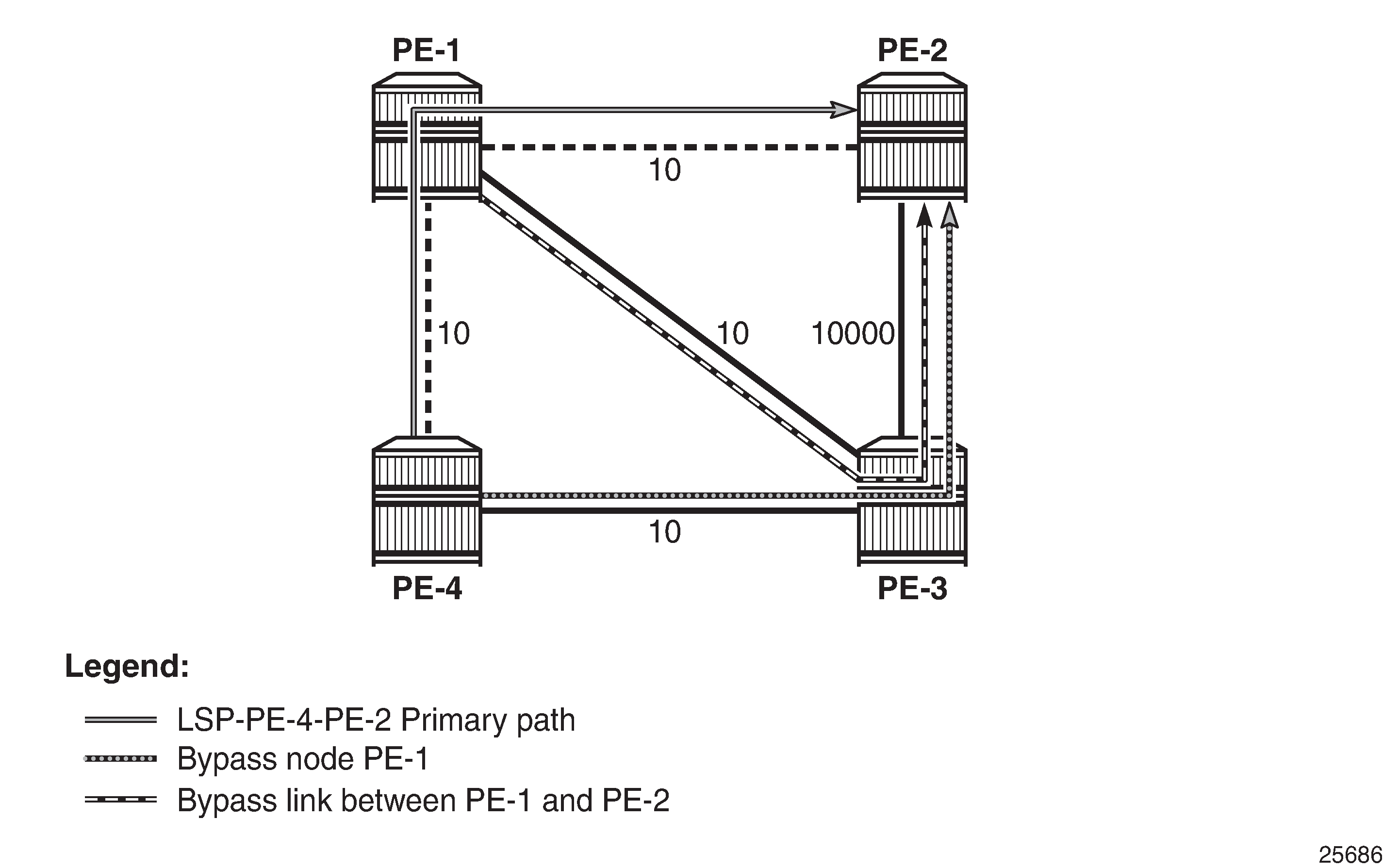
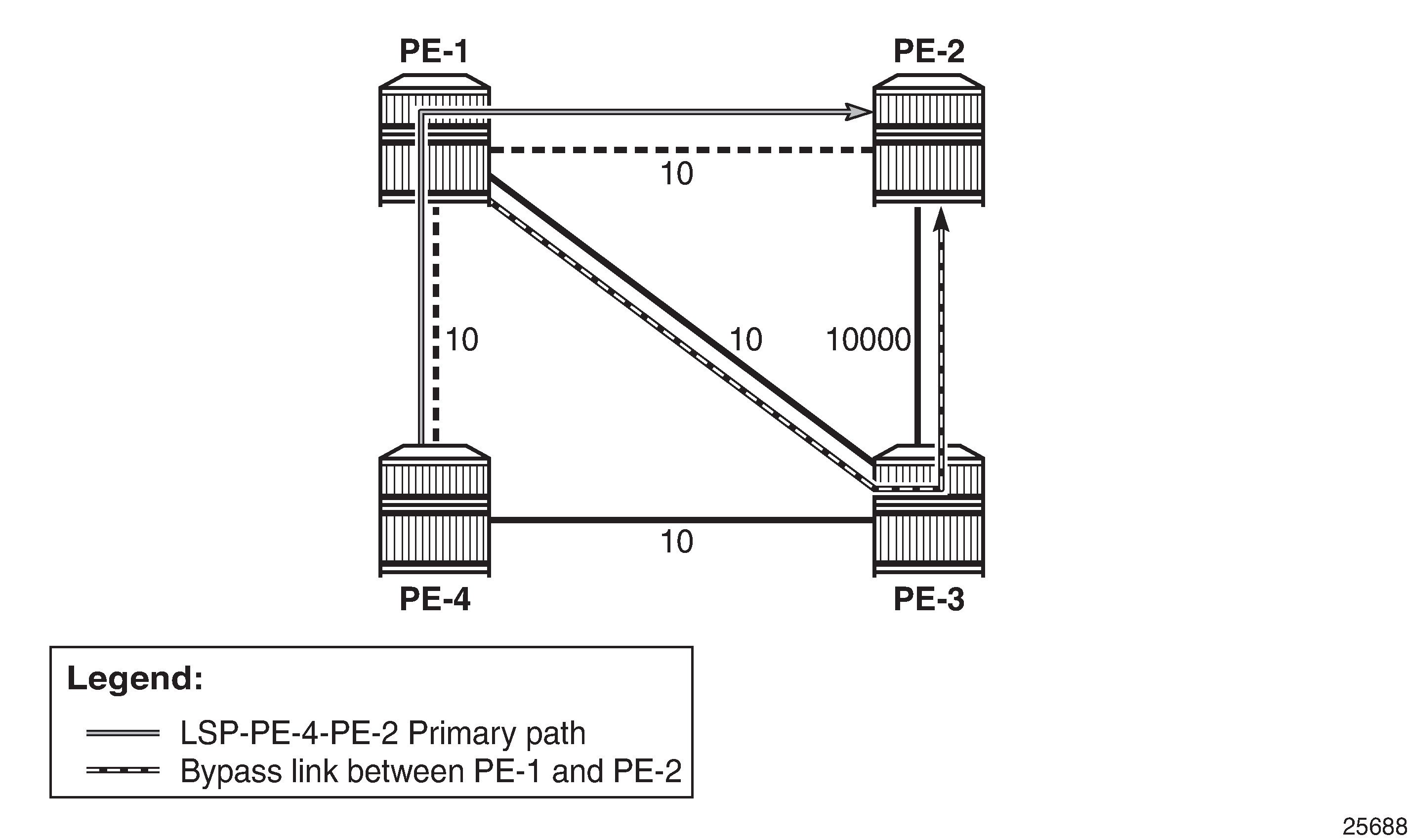
LSP and FRR facility bypass tunnels shows the LSP and the two bypass tunnels: one in PE-4, offering node protection for node PE-1, and another in PE-1, bypassing the link between PE-1 and PE-2.
For each bypass tunnel, an additional RSVP session is set up. The following output shows that, in PE-4, two LSPs are signaled: the primary LSP and the bypass tunnel for node PE-1.
*A:PE-4# show router rsvp session

===============================================================================
RSVP Sessions
===============================================================================
RSVP Session Name
    From                To              Tunnel ID   LSP ID       State
-------------------------------------------------------------------------------
LSP-PE-4-PE-2::dyn
192.0.2.4           192.0.2.2           1           2568         Up

bypass-node192.0.2.1-61441
192.0.2.4           192.168.23.1        61441       2            Up

-------------------------------------------------------------------------------
Sessions : 2
===============================================================================
Similarly, PE-1 has an RSVP session for the primary LSP, but also for the bypass tunnel for the link toward PE-2, as follows:
*A:PE-1# show router rsvp session

===============================================================================
RSVP Sessions
===============================================================================
RSVP Session Name
    From                To              Tunnel ID   LSP ID       State
-------------------------------------------------------------------------------
LSP-PE-4-PE-2::dyn
192.0.2.4           192.0.2.2           1           2568         Up

bypass-link192.0.2.2-61441
192.0.2.1           192.168.23.1        61441       2            Up

-------------------------------------------------------------------------------
Sessions : 2
===============================================================================
PE-3 is only used by the bypass tunnels, as follows:
*A:PE-3# show router rsvp session

===============================================================================
RSVP Sessions
===============================================================================
RSVP Session Name
    From                To              Tunnel ID   LSP ID       State
-------------------------------------------------------------------------------
bypass-link192.0.2.2-61441
192.0.2.1           192.168.23.1        61441       2            Up

bypass-node192.0.2.1-61441
192.0.2.4           192.168.23.1        61441       2            Up

-------------------------------------------------------------------------------
Sessions : 2
===============================================================================
PE-2 terminates the LSP and the bypass tunnels, as follows:
*A:PE-2# show router rsvp session

===============================================================================
RSVP Sessions
===============================================================================
RSVP Session Name
    From                To              Tunnel ID   LSP ID       State
-------------------------------------------------------------------------------
LSP-PE-4-PE-2::dyn
192.0.2.4           192.0.2.2           1           2568         Up

bypass-link192.0.2.2-61441
192.0.2.1           192.168.23.1        61441       2            Up

bypass-node192.0.2.1-61441
192.0.2.4           192.168.23.1        61441       2            Up

-------------------------------------------------------------------------------
Sessions : 3
===============================================================================
FRR one-to-one only supported on numbered interfaces
When FRR one-to-one is enabled on the LSP, the LSP does not use unnumbered interfaces. FRR is reconfigured on the LSP as follows:
# on PE-4:
configure
    router
        mpls
            lsp "LSP-PE-4-PE-2"
                no fast-reroute
                fast-reroute one-to-one
                exit
            exit all
The LSP only comes up if it can use numbered interfaces end-to-end. In this case, the LSP takes the path via PE-3 with CSPF metric 10010, as follows:
*A:PE-4# show router mpls lsp "LSP-PE-4-PE-2" path detail

===============================================================================
MPLS LSP LSP-PE-4-PE-2 Path  (Detail)
===============================================================================
Legend :
    @ - Detour Available              # - Detour In Use
    b - Bandwidth Protected           n - Node Protected
    s - Soft Preemption
    S - Strict                        L - Loose
    A - ABR                           + - Inherited
===============================================================================
-------------------------------------------------------------------------------
LSP LSP-PE-4-PE-2
Path dyn
-------------------------------------------------------------------------------
LSP Name    : LSP-PE-4-PE-2
From             : 192.0.2.4
To               : 192.0.2.2
Admin State      : Up                      Oper State        : Up
Path Name   : dyn
Path LSP ID      : 2574                    Path Type         : Primary
Path Admin       : Up                      Path Oper         : Up
Out Interface    : 1/1/c1/2                Out Label         : 524287
---snip---
Explicit Hops    :
    No Hops Specified
Actual Hops      :
    192.168.34.2(192.0.2.4)                      Record Label        : N/A
 -> 192.168.34.1(192.0.2.3)                      Record Label        : 524287
 -> 192.168.23.1(192.0.2.2)                      Record Label        : 524287
Computed Hops    :
    192.168.34.2(S)
 -> 192.168.34.1(S)
 -> 192.168.23.1(S)
Resignal Eligible: False
Last Resignal    : n/a                     CSPF Metric       : 10010
===============================================================================
* indicates that the corresponding row element may have been truncated.
FRR one-to-one only supported on numbered interfaces shows the LSP in case of FRR one-to-one. Only numbered interfaces are used. Unfortunately, there is no bypass tunnel possible with only numbered interfaces; therefore, there is no protection.
If there is no path available with only numbered interfaces, the LSP remains operationally down with failure code noCspfRouteToDestination". This can be verified by disabling port 1/1/c1/2 toward PE-3, as follows:
# on PE-4:
configure port 1/1/c1/2 shutdown
*A:PE-4# show router mpls lsp "LSP-PE-4-PE-2" path detail

===============================================================================
MPLS LSP LSP-PE-4-PE-2 Path  (Detail)
===============================================================================
---snip---
-------------------------------------------------------------------------------
LSP LSP-PE-4-PE-2
Path dyn
-------------------------------------------------------------------------------
LSP Name    : LSP-PE-4-PE-2
From             : 192.0.2.4
To               : 192.0.2.2
Admin State      : Up                      Oper State        : Down
Path Name   : dyn
Path LSP ID      : 2576                    Path Type         : Primary
Path Admin       : Up                      Path Oper         : Down
Out Interface    : n/a                     Out Label         : n/a
---snip---
Failure Code     : noCspfRouteToDestination
Failure Node : 192.0.2.4
Explicit Hops    :
    No Hops Specified
Actual Hops      :
    No Hops Specified
Computed Hops    :
    No Hops Specified
Resignal Eligible: False
Last Resignal    : n/a                     CSPF Metric       : N/A
===============================================================================
* indicates that the corresponding row element may have been truncated.
The port is enabled again and the LSP configuration is restored to FRR facility, as follows:
# on PE-4:
configure
    port 1/1/c1/2
        no shutdown
    exit all

configure
    router
        mpls
            lsp "LSP-PE-4-PE-2"
                shutdown
                no fast-reroute
                fast-reroute facility
                exit
                sleep 1
                no shutdown
            exit all
FRR bypass not possible on iLER on unnumbered interfaces
FRR facility is not supported on the iLER PE-4 if the bypass is over an unnumbered interface. This restriction only applies to the iLER, not to the LSRs. The interface toward PE-3 is reconfigured as unnumbered, as follows:
# on PE-3:
configure
    router
        interface "int-PE-3-PE-4"
            no address
            unnumbered
        exit
        mpls
            interface "int-PE-3-PE-4"
                te-metric 10
            exit
        exit
    exit all
# on PE-4:
configure
    router
        interface "int-PE-4-PE-3"
            no address
            unnumbered
        exit
        mpls
            interface "int-PE-4-PE-3"
                te-metric 10
            exit
        exit
    exit all
When an interface changes from numbered to unnumbered or the other way around, it is no longer known in the mpls context. Therefore, the interface must be added in the mpls context again. When the interface toward PE-3 is numbered, there is a bypass tunnel in PE-4 to protect node PE-1, but this bypass tunnel cannot be established on an unnumbered interface. The only remaining protection for the LSP is the bypass tunnel originating in PE-1 to protect the link between PE-1 and PE-2, as shown in FRR on iLER: no bypass on unnumbered interfaces.
The following output shows that there is only a detour available in PE-1:
*A:PE-4# show router mpls lsp "LSP-PE-4-PE-2" path detail

===============================================================================
---snip--
-------------------------------------------------------------------------------
LSP LSP-PE-4-PE-2
Path dyn
-------------------------------------------------------------------------------
LSP Name    : LSP-PE-4-PE-2
From             : 192.0.2.4
To               : 192.0.2.2
Admin State      : Up                      Oper State        : Up
Path Name   : dyn
Path LSP ID      : 2580                    Path Type         : Primary
Path Admin       : Up                      Path Oper         : Up
Out Interface    : 1/1/c1/1                Out Label         : 524287
---snip---
Explicit Hops    :
    No Hops Specified
Actual Hops      :
    192.0.2.4, If Index : 2                      Record Label        : N/A
 -> 192.0.2.1, If Index : 4 @                    Record Label        : 524287
 -> 192.0.2.2, If Index : 2                      Record Label        : 524287
Computed Hops    :
    192.0.2.4, If Index : 2(S)
 -> 192.0.2.1, If Index : 4(S)
 -> 192.0.2.2, If Index : 2(S)
Resignal Eligible: False
Last Resignal    : n/a                     CSPF Metric       : 20
===============================================================================
* indicates that the corresponding row element may have been truncated.
In iLER PE-4, there is only the LSP tunnel, no bypass tunnel, as follows:
*A:PE-4# show router rsvp session

===============================================================================
RSVP Sessions
===============================================================================
RSVP Session Name
    From                To              Tunnel ID   LSP ID       State
-------------------------------------------------------------------------------
LSP-PE-4-PE-2::dyn
192.0.2.4           192.0.2.2           1           2580         Up

-------------------------------------------------------------------------------
Sessions : 1
===============================================================================
The original configuration is restored with numbered interfaces between PE-3 and PE-4, as follows:
# on PE-3:
configure
    router
        interface "int-PE-3-PE-4"
            no unnumbered
            address 192.168.34.1/30
        exit
        mpls
            interface "int-PE-3-PE-4"
                te-metric 10
            exit
        exit
    exit all
# on PE-4:
configure
    router
        interface "int-PE-4-PE-3"
            no unnumbered
            address 192.168.34.2/30
        exit
        mpls
            interface "int-PE-4-PE-3"
                te-metric 10
            exit
        exit
    exit all
Admin groups for unnumbered interfaces in RSVP
Administrative groups (link coloring) can be used to calculate a path with the restriction to only include, or exclude, links of a particular admin group (color). Paths can be disjointed from each other, without the need for an explicit hops list. For unnumbered interfaces, an explicit hops list is not an option, but admin groups are.
Two admin groups are configured on all nodes, as follows:
# on all nodes:
configure
    router
        if-attribute
            admin-group "red" value 0
            admin-group "blue" value 1
        exit all
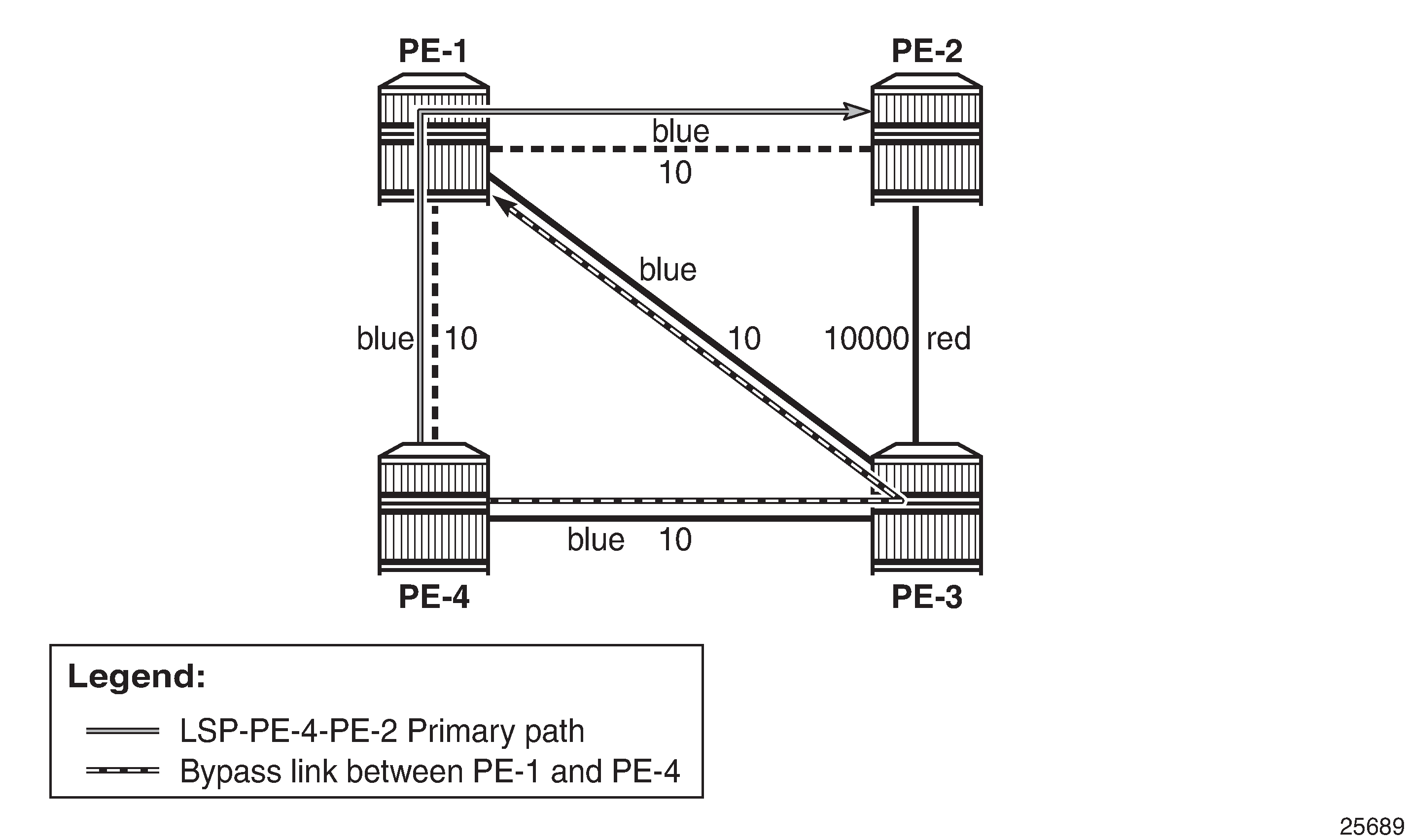
Admin group "blue" is assigned to all MPLS interfaces, except for the link between PE-2 and PE-3; see FRR facility and admin groups.
The admin groups are assigned to the interfaces in the mpls context, as follows:
# on PE-2:
configure
    router
        mpls
            interface "int-PE-2-PE-1"
                admin-group "blue"
            exit
            interface "int-PE-2-PE-3"
                admin-group "red"
            exit
        exit all
To ensure that FRR bypass tunnels only use links belonging to the same admin group, the following is configured on all nodes. It is required on all PLRs.
# on all nodes:
configure
    router
        mpls
            admin-group-frr
        exit all
In the lsp context, the admin group "blue" is included. The option propagate-admin-group implies that the tunnels must use links belonging to the admin group "blue". This is configured for the LSP tunnel, and for the FRR bypass tunnels, as follows:
# on PE-4:
configure
    router
        mpls
            lsp "LSP-PE-4-PE-2"
                to 192.0.2.2
                path-computation-method local-cspf
                metric-type te
                include "blue"
                propagate-admin-group
                fast-reroute facility
                    propagate-admin-group
                exit
                primary "dyn"
                exit
                no shutdown
            exit all
This configuration implies that the link that does not belong to admin group "blue" is excluded, and cannot be used by the LSP nor by a bypass tunnel. Therefore, there is no bypass tunnel to protect node PE-1 and no bypass tunnel originating in PE-1 protecting the link to PE-2. There is a bypass tunnel originating in PE-4 to protect the link between PE-4 and PE-1, as shown in FRR facility and admin groups. The following output shows that a detour is available for link protection in PE-4:
*A:PE-4# show router mpls lsp "LSP-PE-4-PE-2" path detail

===============================================================================
MPLS LSP LSP-PE-4-PE-2 Path  (Detail)
===============================================================================
Legend :
    @ - Detour Available              # - Detour In Use
    b - Bandwidth Protected           n - Node Protected
    s - Soft Preemption
    S - Strict                        L - Loose
    A - ABR                           + - Inherited
===============================================================================
-------------------------------------------------------------------------------
LSP LSP-PE-4-PE-2
Path dyn
-------------------------------------------------------------------------------
LSP Name    : LSP-PE-4-PE-2
From             : 192.0.2.4
To               : 192.0.2.2
Admin State      : Up                      Oper State        : Up
Path Name   : dyn
Path LSP ID      : 2586                    Path Type         : Primary
Path Admin       : Up                      Path Oper         : Up
Out Interface    : 1/1/c1/1                Out Label         : 524284
---snip---
Include Groups   :                         Oper IncludeGroups:
blue                                           blue
Exclude Groups   :                         Oper ExcludeGroups:
None                                           None
---snip---
Explicit Hops    :
    No Hops Specified
Actual Hops      :
    192.0.2.4, If Index : 2 @                    Record Label        : N/A
 -> 192.0.2.1, If Index : 4                      Record Label        : 524284
 -> 192.0.2.2, If Index : 2                      Record Label        : 524282
Computed Hops    :
    192.0.2.4, If Index : 2(S)
 -> 192.0.2.1, If Index : 4(S)
 -> 192.0.2.2, If Index : 2(S)
---snip---
===============================================================================
* indicates that the corresponding row element may have been truncated.
The following output shows two RSVP sessions in PE-4: one for the LSP and one for the bypass tunnel to protect the link between PE-4 and PE-1.
*A:PE-4# show router rsvp session

===============================================================================
RSVP Sessions
===============================================================================
RSVP Session Name
    From                To              Tunnel ID   LSP ID       State
-------------------------------------------------------------------------------
LSP-PE-4-PE-2::dyn
192.0.2.4           192.0.2.2           1           2586         Up

bypass-link192.0.2.1-61460
192.0.2.4           192.168.13.1        61460       30           Up

-------------------------------------------------------------------------------
Sessions : 2
===============================================================================
The configuration is restored as follows:
# on PE-4:
configure
    router
        mpls
            lsp "LSP-PE-4-PE-2"
                fast-reroute
                    no propagate-admin-group
                exit
                no propagate-admin-group
                no include "blue"
            exit
            no admin-group-frr
        exit all
SRLGs for unnumbered interfaces in RSVP
SRLGs allow operators to create automatic secondary LSPs or FRR tunnels that are disjointed from the protected primary tunnel. See chapter Shared Risk Link Groups for RSVP-Based LSPs for more information.
One SRLG group is configured on all nodes, as follows:
# on all nodes:
configure
    router
        if-attribute
            srlg-group "SRLG1" value 1
        exit all
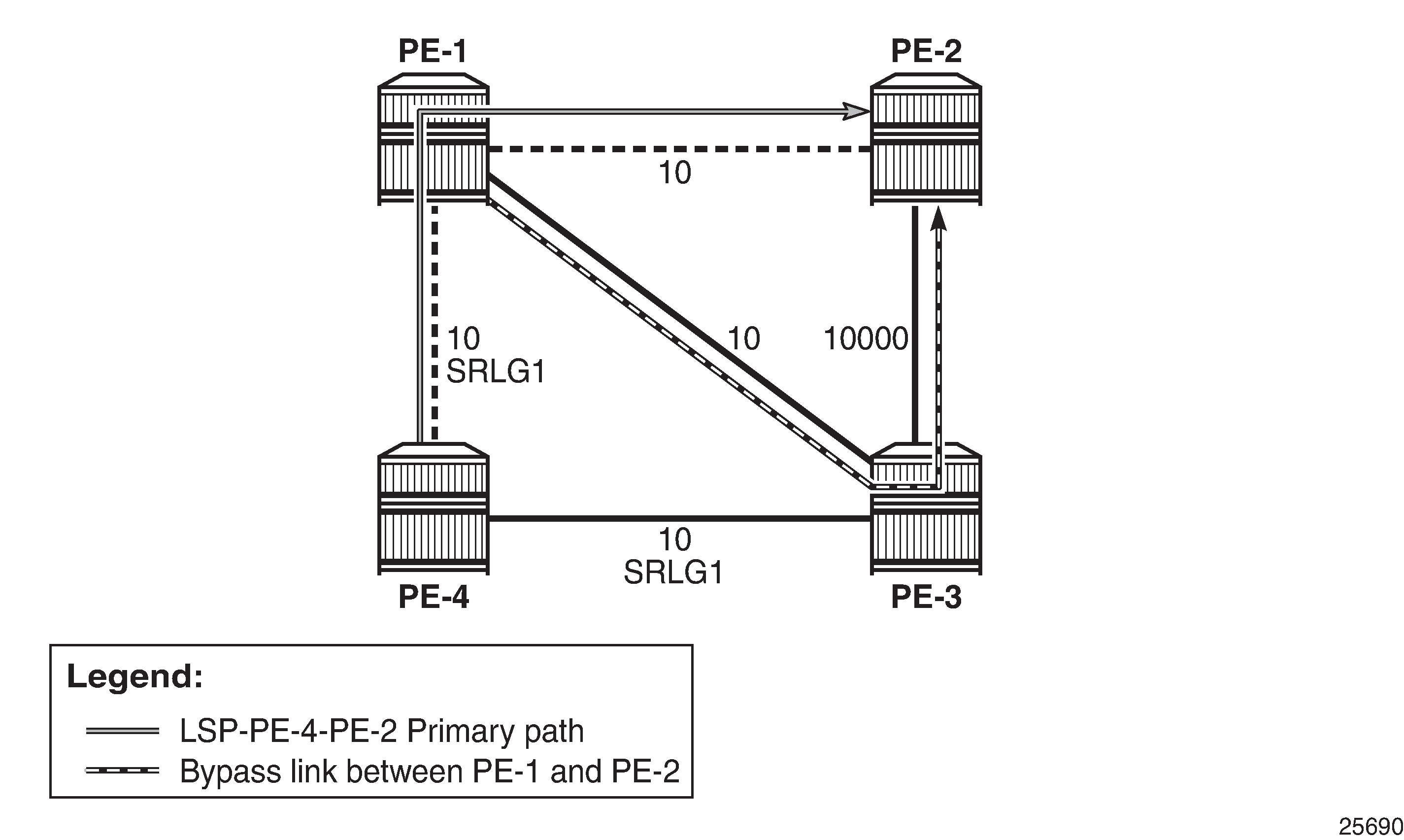
SRLG "SRLG1" is assigned to the interface between PE-4 and PE-1, and to the interface between PE-4 and PE-3, as shown in SRLG-FRR strict: no bypass on PE-4.
The SRLG is assigned to the interfaces in the mpls context, as follows:
# on PE-4:
configure
    router
        mpls
            interface "int-PE-4-PE-1"
                srlg-group "SRLG1"
            exit
            interface "int-PE-4-PE-3"
                srlg-group "SRLG1"
            exit
        exit all
The configuration on PE-1 and PE-3 is similar.
When SRLG for FRR is enabled in strict mode, CSPF does not establish any detour LSP if there is no path that meets the SRLG constraint. This configuration implies that there is no bypass tunnel in PE-4. The following enables SRLG for FRR in strict mode on all nodes:
# on all nodes:
configure
    router
        mpls
            srlg-frr strict
        exit all
Enabling or disabling SRLG for FRR is a system-wide configuration that requires the MPLS routing instance to be manually disabled (shutdown) and then re-enabled (no shutdown), to activate the change. This can be service affecting. Nokia recommends that the operator include the SRLG in the initial network design and implementation to minimize the traffic loss.
The following output shows that there is only a detour available in PE-1:
*A:PE-4# show router mpls lsp "LSP-PE-4-PE-2" path detail

===============================================================================
MPLS LSP LSP-PE-4-PE-2 Path  (Detail)
===============================================================================
Legend :
    @ - Detour Available              # - Detour In Use
    b - Bandwidth Protected           n - Node Protected
    s - Soft Preemption
    S - Strict                        L - Loose
    A - ABR                           + - Inherited
===============================================================================
-------------------------------------------------------------------------------
LSP LSP-PE-4-PE-2
Path dyn
-------------------------------------------------------------------------------
LSP Name    : LSP-PE-4-PE-2
From             : 192.0.2.4
To               : 192.0.2.2
Admin State      : Up                      Oper State        : Up
Path Name   : dyn
Path LSP ID      : 2594                    Path Type         : Primary
Path Admin       : Up                      Path Oper         : Up
Out Interface    : 1/1/c1/1                Out Label         : 524287
---snip---
Explicit Hops    :
    No Hops Specified
Actual Hops      :
    192.0.2.4, If Index : 2                      Record Label        : N/A
 -> 192.0.2.1, If Index : 4 @                    Record Label        : 524287
 -> 192.0.2.2, If Index : 2                      Record Label        : 524287
Computed Hops    :
    192.0.2.4, If Index : 2(S)
 -> 192.0.2.1, If Index : 4(S)
 -> 192.0.2.2, If Index : 2(S)
---snip---
===============================================================================
* indicates that the corresponding row element may have been truncated.
The following output shows that PE-1 has two RSVP sessions: one for the LSP and one for the bypass tunnel to protect the link between PE-1 and PE-2.
*A:PE-1# show router rsvp session

===============================================================================
RSVP Sessions
===============================================================================
RSVP Session Name
    From                To              Tunnel ID   LSP ID       State
-------------------------------------------------------------------------------
LSP-PE-4-PE-2::dyn
192.0.2.4           192.0.2.2           1           2594         Up

bypass-link192.0.2.2-61507
192.0.2.1           192.168.23.1        61507       10           Up

-------------------------------------------------------------------------------
Sessions : 2
===============================================================================
This was the last example for unnumbered interfaces in RSVP. MPLS and RSVP are disabled in all nodes as follows:
# on all nodes:
configure
    router
        rsvp
            shutdown
        exit
        mpls
            shutdown
            no srlg-frr
        exit
    exit all
Unnumbered interfaces in LDP
Link LDP is configured on PE-4, as follows:
# on PE-4:
configure
    router
        ldp
            interface-parameters
                interface "int-PE-4-PE-1" dual-stack
                    ipv4
                        no shutdown
                    exit
                    no shutdown
                exit
                interface "int-PE-4-PE-3" dual-stack
                    ipv4
                        no shutdown
                    exit
                    no shutdown
                exit
            exit all
The configuration of link LDP on the other nodes is similar. Link LDP sessions are established, which can be verified as follows:
*A:PE-4# show router ldp session ipv4

==============================================================================
LDP IPv4 Sessions
==============================================================================
Peer LDP Id         Adj Type  State         Msg Sent  Msg Recv  Up Time
------------------------------------------------------------------------------
192.0.2.1:0         Link      Established   29        30        0d 00:00:50
192.0.2.3:0         Link      Established   30        30        0d 00:00:51
------------------------------------------------------------------------------
No. of IPv4 Sessions: 2
==============================================================================
The Peer LDP Id is the LSR ID, which is the system address, by default. The IP address configured on the unnumbered interface (such as 192.1.2.1) is not used. The following tunnel table shows a distinction between numbered and unnumbered interfaces in the next hop:
*A:PE-4# show router tunnel-table

===============================================================================
IPv4 Tunnel Table (Router: Base)
===============================================================================
Destination           Owner     Encap TunnelId  Pref   Nexthop        Metric
   Color
-------------------------------------------------------------------------------
192.0.2.1/32          ldp       MPLS  65538     9      int-PE-4-PE-1  10
192.0.2.2/32          ldp       MPLS  65539     9      int-PE-4-PE-1  20
192.0.2.3/32          ldp       MPLS  65537     9      192.168.34.1   10
-------------------------------------------------------------------------------
Flags: B = BGP or MPLS backup hop available
       L = Loop-Free Alternate (LFA) hop available
       E = Inactive best-external BGP route
       k = RIB-API or Forwarding Policy backup hop
===============================================================================
For destination 192.0.2.1 or 192.0.2.2, the unnumbered interface toward PE-1 is taken. The next hop is represented by int-PE-4-PE-1. When a node has several unnumbered interfaces, the corresponding next hop values are different, as follows, for PE-1:
*A:PE-1# show router tunnel-table

===============================================================================
IPv4 Tunnel Table (Router: Base)
===============================================================================
Destination           Owner     Encap TunnelId  Pref   Nexthop        Metric
   Color
-------------------------------------------------------------------------------
192.0.2.2/32          ldp       MPLS  65537     9      int-PE-1-PE-2  10
192.0.2.3/32          ldp       MPLS  65538     9      192.168.13.2   10
192.0.2.4/32          ldp       MPLS  65539     9      int-PE-1-PE-4  10
-------------------------------------------------------------------------------
Flags: B = BGP or MPLS backup hop available
       L = Loop-Free Alternate (LFA) hop available
       E = Inactive best-external BGP route
       k = RIB-API or Forwarding Policy backup hop
===============================================================================
The LDP active prefix bindings only contain system addresses, no other loopback prefixes, as follows:
*A:PE-4# show router ldp bindings active prefixes ipv4

===============================================================================
LDP Bindings (IPv4 LSR ID 192.0.2.4)
             (IPv6 LSR ID ::)
===============================================================================
---snip---
===============================================================================
LDP IPv4 Prefix Bindings (Active)
===============================================================================
Prefix                                      Op
IngLbl                                      EgrLbl
EgrNextHop                                  EgrIf/LspId
-------------------------------------------------------------------------------
192.0.2.1/32                                Push
  --                                        524287
Unnumbered                                  1/1/c1/1

192.0.2.1/32                                Swap
524285                                      524287
Unnumbered                                  1/1/c1/1

192.0.2.2/32                                Push
  --                                        524286
Unnumbered                                  1/1/c1/1

192.0.2.2/32                                Swap
524284                                      524286
Unnumbered                                  1/1/c1/1

192.0.2.3/32                                Push
  --                                        524287
192.168.34.1                                1/1/c1/2

192.0.2.3/32                                Swap
524286                                      524287
192.168.34.1                                1/1/c1/2

192.0.2.4/32                                Pop
524287                                        --
  --                                          --

-------------------------------------------------------------------------------
No. of IPv4 Prefix Active Bindings: 7
===============================================================================
For prefixes 192.0.2.1 and 192.0.2.2, the egress next hop is unnumbered. The egress interface for both is 1/1/c1/1. There is no If Index. Local addresses are advertised in LDP address messages, such as:
# on PE-4:
8 2023/03/21 13:24:43.317 UTC MINOR: DEBUG #2001 Base LDP
"LDP: LDP
Send Address packet (msgId 5) to 192.0.2.1:0
Protocol version = 1
Address Family = 1  Number of addresses = 3
Address 1 = 192.0.2.4
Address 2 = 192.1.2.4
Address 3 = 192.168.34.2
"

9 2023/03/21 13:24:43.378 UTC MINOR: DEBUG #2001 Base LDP
"LDP: LDP
Recv Address packet (msgId 5) from 192.0.2.1:0
Protocol version = 1
Address Family = 1  Number of addresses = 3
Address 1 = 192.0.2.1
Address 2 = 192.1.2.1
Address 3 = 192.168.13.1
"
The list of advertised local addresses includes the loopback addresses "loopback1": 192.1.2.1 and 192.1.2.4. These loopback addresses did not occur in the preceding lists of LDP sessions or LDP bindings, but they occur in the LDP session local addresses, as follows:
*A:PE-4# show router ldp session local-addresses ipv4

===============================================================================
LDP Session Local-Addresses
===============================================================================
-------------------------------------------------------------------------------
Session with Peer 192.0.2.1:0,
             Local 192.0.2.4:0
-------------------------------------------------------------------------------
IPv4 Sent Addresses:

                192.0.2.4       192.1.2.4       192.168.34.2

IPv4 Recv Addresses:

                192.0.2.1       192.1.2.1       192.168.13.1
-------------------------------------------------------------------------------
---snip---
===============================================================================
If there were only unnumbered addresses and no additional loopback addresses, only the system address and other loopback addresses would be sent or received. The interface addresses in the list of local addresses are from numbered interfaces.
Configuring the local LSR ID
To use the loopback address "loopback1" in the LDP sessions, the local LSR ID is configured as follows:
# on PE-4:
configure
    router
        ldp
            interface-parameters
                interface "int-PE-4-PE-1"
                    ipv4
                        local-lsr-id interface-name "loopback1"
                        transport-address interface
                        no shutdown
                    exit all
The transport address is the system address, by default, but here it is changed to the address of "loopback1", which is 192.1.2.4. The configuration is similar on PE-1. On PE-2, the system addresses are kept and no additional configuration is required.
LDP hello messages are sent from the transport address to 224.0.0.2 to establish hello adjacencies. The transport address is 192.1.2.4 for the unnumbered interface toward PE-1, and 192.0.2.4 (system address of PE-4) for the numbered interface toward PE-3. LDP hello adjacencies are verified as follows:
*A:PE-4# show router ldp discovery ipv4

===============================================================================
LDP IPv4 Hello Adjacencies
===============================================================================
Interface Name                   Local Addr                              State
AdjType                          Peer Addr
-------------------------------------------------------------------------------
int-PE-4-PE-1                    192.1.2.4:0                             Estab
link                             192.1.2.1:0

int-PE-4-PE-3                    192.0.2.4:0                             Estab
link                             192.0.2.3:0

-------------------------------------------------------------------------------
No. of IPv4 Hello Adjacencies: 2
===============================================================================
The LDP hello adjacencies are established, but the LDP session on the unnumbered interface is non-existent, as follows:
*A:PE-4# show router ldp session ipv4

==============================================================================
LDP IPv4 Sessions
==============================================================================
Peer LDP Id         Adj Type  State         Msg Sent  Msg Recv  Up Time
------------------------------------------------------------------------------
192.0.2.3:0         Link      Established   59        59        0d 00:02:06
192.1.2.1:0         Link      Nonexistent   6         6         0d 00:00:20
------------------------------------------------------------------------------
No. of IPv4 Sessions: 2
==============================================================================
The LDP session is non-existent because the prefix 192.1.2.1/32 is not in the routing table and the LDP session is to be established between 192.1.2.4 and 192.1.2.1. The following export policy is configured and added in the IS-IS context on the nodes:
# on PE-4:
configure
    router
        policy-options
            begin
            policy-statement "export_ISIS"
                entry 10
                    from
                        protocol direct
                    exit
                    action accept
                    exit
                exit
                default-action drop
                exit
            exit
            commit
        exit
        isis
            export "export_ISIS"
        exit
    exit all
The loopback addresses are now exported in IS-IS. When the loopback addresses are in the routing table, the LDP session is established, as follows:
*A:PE-4# show router ldp session ipv4

==============================================================================
LDP IPv4 Sessions
==============================================================================
Peer LDP Id         Adj Type  State         Msg Sent  Msg Recv  Up Time
------------------------------------------------------------------------------
192.0.2.3:0         Link      Established   75        73        0d 00:02:43
192.1.2.1:0         Link      Established   26        27        0d 00:00:57
------------------------------------------------------------------------------
No. of IPv4 Sessions: 2
==============================================================================
The local LSR ID can also be configured for targeted LDP sessions, as follows:
# on PE-4:
configure
    router
        ldp
            targeted-session
                peer 192.1.2.1
                    local-lsr-id "loopback1"
                    no shutdown
                exit all
The configuration on PE-1 is similar for peer 192.0.2.4. On PE-4, the LDP adjacency type is now both link and targeted for peer 192.1.2.1, as follows:
*A:PE-4# show router ldp session ipv4

==============================================================================
LDP IPv4 Sessions
==============================================================================
Peer LDP Id         Adj Type  State         Msg Sent  Msg Recv  Up Time
------------------------------------------------------------------------------
192.0.2.3:0         Link      Established   106       104       0d 00:04:07
192.1.2.1:0         Both      Established   68        70        0d 00:02:21
------------------------------------------------------------------------------
No. of IPv4 Sessions: 2
==============================================================================
Even though the LDP sessions are established, there is no LDP prefix binding for the loopback address, as follows:
*A:PE-4# show router ldp bindings active prefixes ipv4

===============================================================================
LDP Bindings (IPv4 LSR ID 192.0.2.4)
             (IPv6 LSR ID ::)
===============================================================================
---snip---
===============================================================================
LDP IPv4 Prefix Bindings (Active)
===============================================================================
Prefix                                      Op
IngLbl                                      EgrLbl
EgrNextHop                                  EgrIf/LspId
-------------------------------------------------------------------------------
192.0.2.1/32                                Push
  --                                        524287
Unnumbered                                  1/1/c1/1

192.0.2.1/32                                Swap
524285                                      524287
Unnumbered                                  1/1/c1/1

192.0.2.2/32                                Push
  --                                        524286
Unnumbered                                  1/1/c1/1

192.0.2.2/32                                Swap
524284                                      524286
Unnumbered                                  1/1/c1/1

192.0.2.3/32                                Push
  --                                        524287
192.168.34.1                                1/1/c1/2

192.0.2.3/32                                Swap
524286                                      524287
192.168.34.1                                1/1/c1/2

192.0.2.4/32                                Pop
524287                                        --
  --                                          --

-------------------------------------------------------------------------------
No. of IPv4 Prefix Active Bindings: 7
===============================================================================
There is no label mapping for prefix 192.1.2.1/32.
SDPs are created toward all other nodes, as follows:
# on PE-4:
configure
    service
        sdp 411 mpls create
            far-end 192.0.2.1
            ldp
            no shutdown
        exit
        sdp 412 mpls create
            far-end 192.1.2.1
            ldp
            no shutdown
        exit
        sdp 421 mpls create
            far-end 192.0.2.2
            ldp
            no shutdown
        exit
        sdp 431 mpls create
            far-end 192.0.2.3
            ldp
            no shutdown
        exit
    exit all
The following output shows that, between PE-4 and PE-1, there are two LDP SDPs: one using the system address and another using the loopback address 192.1.2.1. The configuration on the other nodes is similar. All SDPs that have a system address as the far end are operationally up, whereas the SDP toward 192.1.2.1 is down:
*A:PE-4# show service sdp

============================================================================
Services: Service Destination Points
============================================================================
SdpId  AdmMTU  OprMTU  Far End          Adm  Opr         Del     LSP   Sig
----------------------------------------------------------------------------
411    0       1556    192.0.2.1        Up   Up          MPLS    L     TLDP
412    0       0       192.1.2.1        Up   Down        MPLS    L     TLDP
421    0       1556    192.0.2.2        Up   Up          MPLS    L     TLDP
431    0       1556    192.0.2.3        Up   Up          MPLS    L     TLDP
----------------------------------------------------------------------------
Number of SDPs : 4
----------------------------------------------------------------------------
Legend: R = RSVP, L = LDP, B = BGP, M = MPLS-TP, n/a = Not Applicable
        I = SR-ISIS, O = SR-OSPF, T = SR-TE, F = FPE
============================================================================
The SDP toward 192.1.2.1 is down because the transport tunnel is down, as follows:
*A:PE-4# show service sdp 412 detail

===============================================================================
Service Destination Point (Sdp Id : 412) Details
===============================================================================
-------------------------------------------------------------------------------
 Sdp Id 412  -192.1.2.1
-------------------------------------------------------------------------------
Description           : (Not Specified)
SDP Id               : 412                   SDP Source         : manual
Admin Path MTU       : 0                     Oper Path MTU      : 0
Delivery             : MPLS
Far End              : 192.1.2.1             Tunnel Far End     :
Oper Tunnel Far End  : 192.1.2.1
LSP Types            : LDP

Admin State          : Up                    Oper State         : Down
Signaling            : TLDP                  Metric             : 0
---snip---
Flags                : TranspTunnDown
---snip---
===============================================================================
The solution is to manually add an LDP prefix binding, as described in the following section.
Configuring the FEC originate
The labels to be used for a manually created LDP prefix binding must be chosen from the range for static labels: from 32 to 18431. This range can be retrieved as follows:
*A:PE-1# show router mpls-labels label-range

===============================================================================
Label Ranges
===============================================================================
Label Type      Start Label End Label   Aging       Available   Total
-------------------------------------------------------------------------------
Static          32          18431       -           18400       18400
Dynamic         18432       524287      0           505852      505856
    Seg-Route   0           0           -           0           0
===============================================================================
To manually add an LDP prefix binding for the loopback prefixes, configure the following:
# on PE-4:
configure
    router
        ldp
            fec-originate 192.1.2.1/32 next-hop 192.0.2.4 interface "int-PE-4-PE-1" swap-label 101
            fec-originate 192.1.2.4/32 pop advertised-label 104
        exit all
# on PE-1:
configure
    router
        ldp
            fec-originate 192.1.2.1/32 pop advertised-label 101
            fec-originate 192.1.2.4/32 next-hop 192.0.2.1 interface "int-PE-1-PE-4" swap-label 104
        exit all
This configuration for unnumbered interfaces includes the interface name, such as int-PE-4-PE-1. This parameter is optional for numbered interfaces.
If the label is chosen from the dynamic range instead of the static range, an error is raised for the pop operation, as follows:
# on PE-1:
configure router ldp fec-originate 192.1.2.1/32 pop advertised-label 100001
                                                                     ^
Error: Invalid parameter. Label value not in allowed range
For interoperability, no error is raised for the swap operation.
As a result, three active LDP bindings are added: one pop operation for the local loopback prefix, and a swap and a push operation for the remote loopback prefix, as follows:
*A:PE-4# show router ldp bindings active prefixes ipv4

===============================================================================
LDP Bindings (IPv4 LSR ID 192.0.2.4)
             (IPv6 LSR ID ::)
===============================================================================
---snip---
===============================================================================
LDP IPv4 Prefix Bindings (Active)
===============================================================================
Prefix                                      Op
IngLbl                                      EgrLbl
EgrNextHop                                  EgrIf/LspId
-------------------------------------------------------------------------------
192.0.2.1/32                                Push
  --                                        524287
Unnumbered                                  1/1/c1/1

192.0.2.1/32                                Swap
524285                                      524287
Unnumbered                                  1/1/c1/1

192.0.2.2/32                                Push
  --                                        524286
Unnumbered                                  1/1/c1/1

192.0.2.2/32                                Swap
524284                                      524286
Unnumbered                                  1/1/c1/1

192.0.2.3/32                                Push
  --                                        524287
192.168.34.1                                1/1/c1/2

192.0.2.3/32                                Swap
524286                                      524287
192.168.34.1                                1/1/c1/2

192.0.2.4/32                                Pop
524287                                        --
  --                                          --

192.1.2.1/32                                Push
  --                                        101
Unnumbered                                  1/1/c1/1

192.1.2.1/32                                Swap
524283                                      101
Unnumbered                                  1/1/c1/1

192.1.2.4/32(S)                             Pop
104                                           --
  --                                          --

-------------------------------------------------------------------------------
No. of IPv4 Prefix Active Bindings: 10
===============================================================================
The following output shows that the SDPs are all operationally up, including the one toward the loopback address:
*A:PE-4# show service sdp

============================================================================
Services: Service Destination Points
============================================================================
SdpId  AdmMTU  OprMTU  Far End          Adm  Opr         Del     LSP   Sig
----------------------------------------------------------------------------
411    0       1556    192.0.2.1        Up   Up          MPLS    L     TLDP
412    0       1556    192.1.2.1        Up   Up          MPLS    L     TLDP
421    0       1556    192.0.2.2        Up   Up          MPLS    L     TLDP
431    0       1556    192.0.2.3        Up   Up          MPLS    L     TLDP
----------------------------------------------------------------------------
Number of SDPs : 4
----------------------------------------------------------------------------
Legend: R = RSVP, L = LDP, B = BGP, M = MPLS-TP, n/a = Not Applicable
        I = SR-ISIS, O = SR-OSPF, T = SR-TE, F = FPE
============================================================================
LDP FRR Loop-Free Alternate on unnumbered interfaces
LDP FRR Loop-Free Alternate (LFA) is supported on unnumbered interfaces and on numbered interfaces. For information about LDP FRR LFA, see chapter MPLS LDP FRR using ISIS as IGP. LDP FRR LFA can be configured as follows:
# on all nodes:
configure
    router
        ip-fast-reroute
        isis
            loopfree-alternates
            exit
        exit
        ldp
            fast-reroute
        exit
    exit all
Enabling FRR LFA is a local decision. In this configuration, it is configured on all nodes. The LFA coverage can be retrieved as follows:
*A:PE-4# show router isis lfa-coverage

===============================================================================
Rtr Base ISIS Instance 0 LFA Coverage
===============================================================================
Topology         Level   Node           IPv4                IPv6
-------------------------------------------------------------------------------
IPV4 Unicast     L1      3/3(100%)      7/7(100%)           0/0(0%)
IPV6 Unicast     L1      0/0(0%)        0/0(0%)             0/0(0%)
IPV4 Multicast   L1      0/0(0%)        0/0(0%)             0/0(0%)
IPV6 Multicast   L1      0/0(0%)        0/0(0%)             0/0(0%)
IPV4 Unicast     L2      0/0(0%)        7/7(100%)           0/0(0%)
IPV6 Unicast     L2      0/0(0%)        0/0(0%)             0/0(0%)
IPV4 Multicast   L2      0/0(0%)        0/0(0%)             0/0(0%)
IPV6 Multicast   L2      0/0(0%)        0/0(0%)             0/0(0%)
===============================================================================
There is protection for the three other nodes and for all remote prefixes in the routing table, which can be verified as follows:
*A:PE-4# show router route-table alternative

===============================================================================
Route Table (Router: Base)
===============================================================================
Dest Prefix[Flags]                            Type    Proto     Age        Pref
      Next Hop[Interface Name]                                   Metric
      Alt-NextHop                                                Alt-
                                                                 Metric
-------------------------------------------------------------------------------
192.0.2.1/32                                  Remote  ISIS      00h44m43s  15
       int-PE-4-PE-1                                                10
       192.168.34.1 (LFA)                                           20
192.0.2.2/32                                  Remote  ISIS      00h44m43s  15
       int-PE-4-PE-1                                                20
       192.168.34.1 (LFA)                                           30
192.0.2.3/32                                  Remote  ISIS      00h21m48s  15
       192.168.34.1                                                 10
       int-PE-4-PE-1 (LFA)                                          20
192.0.2.4/32                                  Local   Local     00h53m42s  0
       system                                                       0
192.1.2.1/32                                  Remote  ISIS      00h06m44s  15
       int-PE-4-PE-1                                                10
       192.168.34.1 (LFA)                                           20
192.1.2.2/32                                  Remote  ISIS      00h06m43s  15
       int-PE-4-PE-1                                                20
       192.168.34.1 (LFA)                                           30
192.1.2.4/32                                  Local   Local     00h44m44s  0
       loopback1                                                    0
192.168.13.0/30                               Remote  ISIS      00h06m44s  160
       int-PE-4-PE-1                                                10
       192.168.34.1 (LFA)                                           20
192.168.23.0/30                               Remote  ISIS      00h21m48s  15
       192.168.34.1                                                 10010
       int-PE-4-PE-1 (LFA)                                          10020
192.168.34.0/30                               Local   Local     00h21m49s  0
       int-PE-4-PE-3                                                0
-------------------------------------------------------------------------------
No. of Routes: 10
Flags: n = Number of times nexthop is repeated
       Backup = BGP backup route
       LFA = Loop-Free Alternate nexthop
       S = Sticky ECMP requested
===============================================================================
For unnumbered interfaces, the interface name is shown (int-PE-4-PE-1); for numbered interfaces, the next hop IP address is shown (192.168.34.1). The LFA type is link protection for the three nodes, as follows:
*A:PE-4# show router isis topology lfa detail

===============================================================================
Rtr Base ISIS Instance 0 Topology Table
===============================================================================
-------------------------------------------------------------------------------
IS-IS IP paths (MT-ID 0),   Level 1
-------------------------------------------------------------------------------
Node      : PE-1.00
Nexthop   : PE-1
Interface : int-PE-4-PE-1
SNPA      : none                             Metric      : 10

LFA nh    : PE-3
LFA intf  : int-PE-4-PE-3                    LFA Metric  : 20
LFA type  : linkProtection

Node      : PE-2.00
Nexthop   : PE-1
Interface : int-PE-4-PE-1
SNPA      : none                             Metric      : 20

LFA nh    : PE-3
LFA intf  : int-PE-4-PE-3                    LFA Metric  : 30
LFA type  : linkProtection

Node      : PE-3.00
Nexthop   : PE-3
Interface : int-PE-4-PE-3
SNPA      : none                             Metric      : 10

LFA nh    : PE-1
LFA intf  : int-PE-4-PE-1                    LFA Metric  : 20
LFA type  : linkProtection

===============================================================================
The LFA protection is shown in LDP FRR LFA link protection on PE-4.
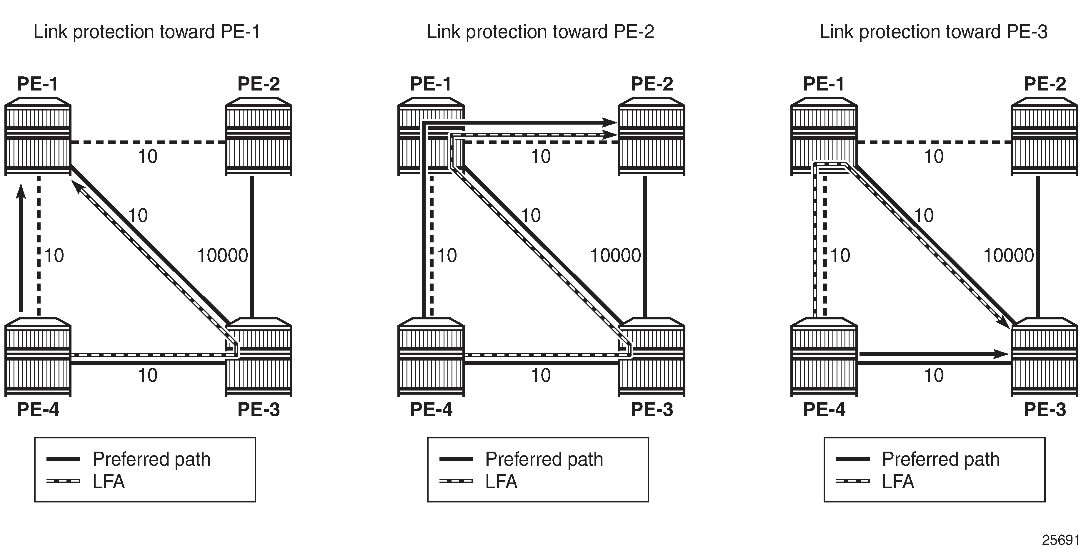
The LDP bindings for FRR LFA indicate alternate (BU) in the list, as follows:
*A:PE-4# show router ldp bindings prefixes ipv4

===============================================================================
LDP Bindings (IPv4 LSR ID 192.0.2.4)
             (IPv6 LSR ID ::)
===============================================================================
Label Status:
        U - Label In Use, N - Label Not In Use, W - Label Withdrawn
        WP - Label Withdraw Pending, BU - Alternate For Fast Re-Route
        e - Label ELC
FEC Flags:
        LF - Lower FEC, UF - Upper FEC, M - Community Mismatch,
        BA - ASBR Backup FEC
===============================================================================
LDP IPv4 Prefix Bindings
===============================================================================
Prefix
Peer                                        FEC-Flags
IgrLbl                                      EgrLbl
EgrNextHop                                  EgrIntf/LspId
-------------------------------------------------------------------------------
192.0.2.1/32
192.0.2.3:0
524285U                                     524286BU
192.168.34.1                                1/1/c1/2

192.0.2.1/32
192.1.2.1:0
  --                                        524287
Unnumbered                                  1/1/c1/1

192.0.2.2/32
192.0.2.3:0
524284U                                     524285BU
192.168.34.1                                1/1/c1/2

192.0.2.2/32
192.1.2.1:0
524284N                                     524286
Unnumbered                                  1/1/c1/1

192.0.2.3/32
192.0.2.3:0
  --                                        524287
192.168.34.1                                1/1/c1/2

192.0.2.3/32
192.1.2.1:0
524286U                                     524285BU
Unnumbered                                  1/1/c1/1

192.0.2.4/32
192.0.2.3:0
524287U                                       --
  --                                          --

192.0.2.4/32
192.1.2.1:0
524287U                                       --
  --                                          --

192.1.2.1/32
192.0.2.3:0
524283U                                     524283BU
192.168.34.1                                1/1/c1/2

192.1.2.1/32
192.1.2.1:0
  --                                        101
Unnumbered                                  1/1/c1/1

192.1.2.4/32
192.0.2.3:0
104U                                          --
  --                                          --

192.1.2.4/32
192.1.2.1:0
104U                                          --
  --                                          --

-------------------------------------------------------------------------------
No. of IPv4 Prefix Bindings: 12
===============================================================================
Conclusion
Unnumbered interfaces were initially supported for SONET/SDH/ATM/FR, and later also on Ethernet access ports. IS-IS adjacencies and OSPF neighbors can be established on unnumbered interfaces. This chapter showes that unnumbered interfaces can be added to RSVP or LDP. Most features that are supported on numbered interfaces are also supported on unnumbered interfaces.